manual d90k drill stair - power step
TRANSCRIPT

PSA-D90K 13-3-12
MODULATING STAIR
Manual for Sandvik D90K Drill
Model No.D90K
Serial No. D90K-001
Date Manufactured: March 2011

Pg2PSA-D90K 13-3-12
MODULATING STAIR
D90K Drill
CONTENTS
Page 3 Section 1 Installation and Mounting instructions
Installation Drawings
Maintenance Notes
15 Section 2 Recommended Maintenance procedure
16 Section 3 Operating Procedure
Section 4 Drawings and Repair Parts lists
17 4 Assembly Complete
18 4-1 Stair Mounting Frame Assembly
Parts List
20 4-2 Head Frame Assembly
Parts List
21 4-3 Stair Assembly
Parts List
23 4-4 Handrail Assemblies
Parts List
24 4-5 Hydraulic Cylinder
Parts List
Valve Diagram
26 4-6 Power Pack
Parts List
29 4-7 Electrical Controls
Parts List
Electrical System Wiring Diagrams

Pg3PSA-D90K 13-3-12
MODULATING STAIR
D90K Drill
Section 1 Installation and Mounting Instructions Dwg. 24 575
NOTE
Follow all on-site/Mine lifting and safety procedures when installing
Power Step Stairs to Drill (D90K)
PROCEDURE.
These Drills are offered with different walkway and platform options. Check that the
machine that is to be fitted with the Power Step Drill Stair can accomodate the structure
needed to support the stair without signifigant modification. Especially check for the
following:
- clear space for the front support beam per View Z-1 and Detail Y and for the inner
attachment cleat per Detail W.
- clear space for the rear support beam per View Z-1 and Detail X and for the inner
attachment cleat per Detail V.
Notify Power Step if any aspects of the build of the machine will prevent installation of the
stair per this drawing and the other installation drawings. Note that the top ends of the
OEM struts that support the cabin, walkways and platforms and their top attachment
structures are not shown on this drawing.

Pg4PSA-D90K 13-3-12
MODULATING STAIR
D90K Drill
Section 1 Installation and Mounting Instructions Dwg. 24575 (Cont.)
VIEW Z-2 SIDE ELEVATIONVIEW Z-3 FRONT ELEVATION
VIEW Z-1 PLAN
DETAIL Y DETAIL X

Pg5PSA-D90K 13-3-12
MODULATING STAIR
D90K Drill
Section 1 Installation and Mounting Instructions Dwg. 24576

Pg6PSA-D90K 13-3-12
MODULATING STAIR
D90K Drill
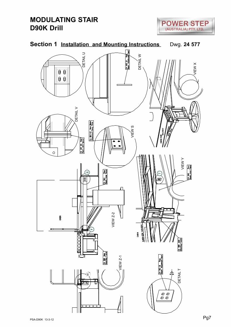
Section 1 Installation and Mounting Instructions Dwg. 24577
NOTE
Follow all on-site/Mine lifting and safety procedures when installing
Power Step Stairs to Drill (D90K)
PROCEDURE
See Drawing 24577 Page 7
1. Bolt the Main Mounting Frame 24 566 to the Main Mounting Pad. Use temporary
props to suit (not shown) to make the frame vertical despite its' limited support
from the drill structure.
2. Fit the Rear Beam Inner Piece to the Main Mounting Frame by bolting its' end
flange to the mating flange on the mounting frame. Attach the Rear Beam
Attachment Cleat to the end of the Beam per Detail T and weld it to the web of the
fabricated box chassis beam per Details T and View S. Note that Spacers 24 577
05 can be fitted in the flange joint to suit and there is length adjustment possible in
the slotted holes of the Attachment Cleat to accommodate build variations in the
drill structure and walkways. If insufficient accommodation is possible with the
spacers and slotted holes, the Rear Beam can be lengthened (by cutting and
inserting material from 24 572 03 Spare Beam Section 3) or shortened to suit.
Locate the attachment cleat on the web of the chassis beam so that the flange-
jointed Rear Beam runs straight from the Fixed Mounting Frame through to the
attachment cleat - measure and locate to suit.
Use this drawing and undertake this work in conjunction with drawing 25 578
PROCEDURE
See Drawing 24577 Page 7
Attach cleats 24 554 01 & 02 to drill structure with preliminary welds per Detail X
Pg7PSA-D90K 13-3-12
MODULATING STAIR
D90K Drill
Section 1 Installation and Mounting Instructions Dwg. 24 577
VIE
W Y
VIE
W S
VIE
W X
DE
TA
ILT
DE
TA
ILV
DE
TA
ILU
DE
TA
ILW
VIE
W Z
-2
VIE
W Z
-1
W

Pg8PSA-D90K 13-3-12
MODULATING STAIR
D90K Drill
Section 1 Installation and Mounting Instructions Dwg. 24 578
VIE
W Z
-2V
IEW
Z-3
DE
TA
ILY
DE
TA
ILX
DE
TA
ILW
VIE
W Z
-1

Pg9PSA-D90K 13-3-12
MODULATING STAIR
D90K Drill
Section 1 Installation and Mounting Instructions Dwg. 24 579
PROCEDURE
See Drawing 24577 Page 10
Use this drawing and undertake this work in conjunction with drawing 25 578
1. Per Views Z-1 and Y, attach the Mounting Struts to the Main Mounting Frame and
then attach the other end of the struts to the Front Beam, Outer. Temporarily
support the Front Beam, Outer high up under the Cabin-Side Walkway.
2. Per Details U, R & S, tackweld the Front Beam Bolting Pad under the inner border
beam of the Cabin-Side Walkway. Bolt the Front Beam, Outer to the bolting pad.
3. Per Details Q & T, bolt the Front Beam End Mounting to the bolting pad on the top
of the front beam near its' outer end. Tackweld the the Mounting to the outer border
member of the cabin-side walkway. The beam is supplied with the bolting pad
tackwelded in place - if necessary move the bolting pad and mounting along the
beam so as to move the 'T' plate of the mounting so it lands against the border
member of the walkway ready for welding.
4. Bolt the Front Beam Inner to the Front Beam Cleats and the bolting flange of the
Front Beam Outer per View Y and Details W & V. Fit Spacers (per Detail V) and
use the slotted holes in the front flange cleats (per Detail W) to adjust the length of
the beam to suit. If these options do not provide sufficient adjustment, shorten or
lengthen (using material from 24 572 01 Spare Beam) the inner beam as required.
5. Upgrade the various tackwelds employed during this installation to the standards
shown in Details U, T, Q and W. Tighten all the bolts used with the mountings.
6. Per View Z-2, trim the length of the Front Bram, Outer and weld on the end cap.
If, because of the location of the OEM struts under the cabin and cabin-side
walkway or for another reason, the front mounting beam cannot be located as per
this drawing and drawing 24 578, extend (using material from 24 572 02 Spare
Beam) or shorten 24 561 Struts and fit the beam forward or backward of the
location herein.

Pg10PSA-D90K 13-3-12
MODULATING STAIR
D90K Drill
Section 1 Installation and Mounting Instructions Dwg. 24 579
DE
TA
ILU D
ETA
ILR
DE
TA
ILQ
DE
TA
ILW
VIE
W Z
-2 -
SID
E E
LE
VA
TIO
N
VIE
W Z
-1 -
PL
AN
VIE
W
DE
TA
ILS

Pg11PSA-D90K 13-3-12
MODULATING STAIR
D90K Drill
Section 1 Installation and Mounting Instructions Dwgs. 24580 & 24581
PROCEDURE.
See Drawing 24580 Page 12
1. Fit the stair set to the fixed mounting frame.
2. Fit the hydraulic power pack per View Y and Detail V. Fit the electrical wiring and
complete the hydraulic circuit.
3. Fit the Landing Deck Extension to the fixed mounting frame per View X.
4. Fit the Drill Deck Extension to the side of the drill deck and the fixed mounting
frame per View Y and Details W-1 and W-2. Shorten the original deck handrail
and toeboard per View Y and Detail W-1. Align the foot of the Extension with the
bolting pad on the fixed mounting frame, weld the extension bolting pad 24 569 05
to the side of the original deck and then bolt the extension to the two bolting pads.
Bolt the extension handrail to the toeboard of the deck extension per View Y.
5. Weld the Inner Handrail to the OEM handrail beside the fixed stair handrail per
Detail U.
See Drawing 24581 Page 13
1. Per Views Z-1, Z-2 & Z-3, attach the Mounting, Stowed Position Guide to the side
of the drill deck. Trim 'Leg 1' per View Z-1 to suit the step in alignment of the deck
panels. Align the plate of the mounting with the Stowed Stair Locator Blade when
the stair is raised to the stowed, horizontal position per Detail V.
2. Adjust the height of the locator socket assembly per Detail V.
NOTE
Follow all on-site/Mine lifting and safety procedures when installing
Power Step Stairs to Drill (D90K)

Pg12PSA-D90K 13-3-12
MODULATING STAIR
D90K Drill
Section 1 Installation and Mounting Instructions Dwg. 24580
DE
TA
ILU
DE
TA
ILV
VIE
W W
.2
DE
TA
ILW
.1
VIE
W X
VIE
W Y
VIE
W Z

Pg13PSA-D90K 13-3-12
MODULATING STAIR
D90K Drill
Section 1 Installation and Mounting Instructions Dwg. 24581
DE
TA
ILW
DE
TA
ILX
DE
TA
ILY
DE
TA
ILU
DE
TA
ILV
VIE
W Z
-1
VIE
W Z
-2V
IEW
Z-3

Pg14PSA-D90K 13-3-12
MODULATING STAIR
D90K Drill
Section 1 Installation and Mounting Instructions
Maintenance Notes
NOTE
Follow all on-site/Mine lifting and safety procedures when installing
Power Step Stairs to Drill (D90K)
WARNING
Raising the POWER STEP Stair by external means can create a vacuum in the hydraulic
cylinder and allow air into the hydraulic system, defeating the inherent safety features of
the POWER STEP.
This must be avoided, to maintain safe operation of the POWER STEP.
In instances where the use of external means to raise the Ladder must be used, please
follow the following instructions:
Loosen hard plumbed hydraulic lines on cylinder side of lock valve (on cylinder.)
Raise Stair by available means.
Note: Make necessary arrangements to collect displaced oil, and be aware that air enters
the piston side of the cylinder as platform is raised.
Lock in raised position.
Re-tighten hydraulic fittings.
SECURE THE STAIR IN THE RAISED POSITION, MECHANICALLY, CHAIN & TAG-OUT
THE POWER STEP
To recommission the POWER STEP:
Loosen hydraulic fittings on cylinder side of lock valve.
Note: Collect displaced oil.
Lower Stair to lowest position, using alternate safety approved means, fully retracting
cylinder. Ensure all personnel are clear of step radius.
Operate electrical control switch to purge air from the hydraulic line systems, lock valve
and cylinder.
Tighten the hydraulic fittings either side of lock valve to restriction fitting.
Cycle step unloaded several times to purge all air from hydraulic system.
The Power Step will not operate correctly if there is any air in the hydraulic circuit (due to
the incorrect operation of the lock valve).

Daily
Visually check stairway and structure for damage, loose components,
handrails, etc.
Check for hydraulic oil leaks from hydraulic cylinder, plumbing and hoses.
Notify the appropriate supervisor for any observed damage or malfunction.
500 Hours
Grease the nipples on the pivot shaft.
Check main mounting bolts for torque.
Check hydraulic oil level in power pack and top up as necessary. (Stair in lowered
position).
Top up using same hydraulic oil as used in hydraulics of machine.
Thoroughly check all electrical wiring for damage, replace as necessary.
Repeat daily check as above
5000 Hours
Change hydraulic oil in tank of hydraulic power pack (5.0 litres).
It is recommended that the same hydraulic oil be used in the power pack as the
hydraulics of the machine.
Grease pivot shaft grease nipples.
Check and inspect all main bolts on stairway system.
Retorque if required.
Repeat daily check as above.
NOTE: Check all Bushes every service including Cylinder, Ladder and Steps for
wear and replace as needed.
Pg15PSA-D90K 13-3-12
MODULATING STAIR
D90K Drill
Section 2 Recommended Maintenance Procedure

Pg16PSA-D90K 13-3-12
MODULATING STAIR
D90K Drill
Section 3 Operating Procedure
Lower Stair
Position machine in a level safe area before lowering Stair.
If Drill is in operation - retract drill bit from ground - stop operation - apply hand
brake - maintain hydraulic jacks in position - lower the stair.
Height of the Drill platform from the ground is not relevant to the Stair operation.
The modulating step treads will self-adjust to maintain a horizontal level at any Drill
platform height.
To operate the Stair hold the switch in the down position.
Once the Stair is lowered to the ground level, release the switch.
Raise Stair
Ascend the Stair
Ensure area around the Stair is clear.
Hold down the switch to raise the Stair.
When the Stair is fully stowed the proximity switch will alert the motor that the Stair
is fully stowed. Release the switch.
NOTE
Follow all on-site/Mine lifting and safety procedures when operating
Power Step Stairs for Drill (D90K)
OPERATING NOTES
NOTE: FLOW CONTROL VALVE ADJUSTMENT:
The valve should be positioned to restrict the flow and speed of the Power Step when
lowering. Adjust the knob on top of the valve by turning left or right (clockwise) when the
step is being lowered, until it is lowering at a safe and reasonable speed.
When it is adjusted, lock the adjusting knob by tightening the grub screw located on the
side of the knob.
NOTE: MAGNETIC 'GO' SWITCH ADJUSTMENT:
The switch target trigger area is located on the opposite side and end from the cable entry
point on the switch. Once it is mounted to the switch bracket, adjust the switch in or out
from the stair steel trigger point, to be within 3mm - 10mm from touching each other when
the stair is in the desired rest position.
[DO NOT EXCEED 10MM DISTANCE BETWEEN THE SWITCH AND STRIKER PLATE].
Test by raising and lowering the Power Step a couple of times and adjust again if
necessary.

PSA-D90K 13-3-12
MODULATING STAIR
D90K Drill
Section 4 Assembly Complete 23 400
Pg17

Pg18PSA-D90K 13-3-12
MODULATING STAIR
D90K Drill
Section 4-1 Stair Mounting Frame Assembly

Pg19PSA-D90K 13-3-12
MODULATING STAIR
D90K Drill
Section 4-1 Stair Mounting Frame Assembly
Item Part No. Part Name Qty
1
2
3
4
5
6
7
8
9
10
10A
11A
11B
12
13
14
15
16
17
18
19
20
21
22
23
24
25
26
27
28
29
30
31
32
33
34
PS-24566
PS-24564
PS-24561
PS-24563
PS-24559
PS-24571
PS-24568
PS-24555
PS-24558
PS-24562-01
PS-24562-02
PS-24554-01
PS-24554-02
PS-24560
PS-24557-03
PS-24553-04
PS-24554-04
PS-24557-05
CPS-M24X80ZP
CPS-M20X90NZP
CPS-M20X50NZP
CPS-M16X100NZP
CPS-M16X85NZP
CPS-M16X60NZP
CPS-M16X50NZP
CPS-M16X40NZP
CPS-M12X25NZP
CPS-M12X20NZP
PS-M24NZP
CPS-M20NZP
CPS-M16NZP
CPS-M12NZP
PS-M24WH
CPS-M20WH
CPS-M16WH
CPS-M12WH
MAIN MOUNTING FRAME
REAR BEAM INNER PIECE
MOUNTING STRUTS
FRONT BEAM OUTER PIECE
FRONT MOUNTING BEAM INNER
MOUNTING-STOWED POSITION GUIDE
DRILL DECK EXTENSION
MAIN MOUNTING PAD
LANDING DECK EXTENSION (Incl. Flange&Pad)
REAR BEAM ATTACHMENT CLEAT
REAR BEAM ATTACHMENT CLAMP PLATE
FRONT BEAM ATTACHMENT CLEAT -TOP
FRONT BEAM ATTACHMENT CLEAT -BOTTOM
FRONT BEAM END MOUNTING
FRONT BEAM BOLTING BLOCK
FRONT BEAM JOINT SPACER
FRONT BEAM CLAMP PLATE
REAR BEAM JOINT SPACER
BOLT-M24 x 80
BOLT-M20 x 90
BOLT-M20 x 50
BOLT-M16 x 100
BOLT-M16 x 85
BOLT-M16 x 60
BOLT-M16 x 50
BOLT-M16 x 40
BOLT-M12 x 25
BOLT-M12 x 20
NUT-M24
NUT-M20
NUT-M16
NUT-M12
WASHER-HARDENED-M24
WASHER-HARDENED-M20
WASHER-HARDENED-M16
WASHER-HARDENED-M12
1
1
1
1
1
1
1
1
1
1
1
1
1
1
1
4
1
5
6
4
6
4
4
4
4
4
4
8
6
8
16
8
10
16
42
16

Pg20PSA-D90K 13-3-12
MODULATING STAIR
D90K Drill
Section 4-2 Head Frame Assembly
Item Part No. Part Name Qty
1
2
3
4
5
6
7
8
9
10
11
12
13
14
15
PS-24566
PS-23403
PS-80103A-SLD
PS-62999
PS-21260
PS-21271
PS-21718
PS-21107-LB
CPS-M20X50ZP
CPS-M12X130ZP
CPS-M8X120NZP
CPS-M8NN
CPS-M20WH
CPS-M12WH
CPS-M8WH
HEAD FRAME
POWER UNIT MOUNTING
POWER PACK ASSEMBLY
HYDRAULIC CYLINDER ASSEMBLY
MAIN PIVOT PIN
SPACER WASHER
PIVOT BUSHES
MOTOR ENCLOSURE BRACKET
BOLT-M20 x 50
BOLT-M12 x 130
BOLT-M8 x 120
NUT-NYLOC-M8
WASHER-HARDENED-M20
WASHER-HARDENED-M12
WASHER-HARDENED-M8
1
1
1
1
1
2
2
2
6
4
2
2
6
8
4
See Page 24

Pg21PSA-D90K 13-3-12
MODULATING STAIR
D90K Drill
Section 4-3 Stair Assembly - (See Assy 23400)

Pg22PSA-D90K 13-3-12
MODULATING STAIR
D90K Drill
Section 4-3 Stair Assembly - (See Assy 23400)
Item Part No. Part Name Qty
1
2
3
4
5
6
7
8
9
10
11
12
13
14
15
16
17
18
19
20
21
22
23
24
PS-23410A
PS-23411
PS-23404
PS-21251B
PS-24523-01
PS-24519
PS-24520
PS-24521
PS-24523-02
PS-24414
PS-M20X140ZP
PS-M20X110ZP
CPS-M12X100ZP
CPS-M12X30ZP
CPS-M12X25CAP/SCREW
CPS-M8X25ZP
CPS-M20NN
CPS-M12NN
CPS-M12NZP
CPS-M8NZP
CPS-M20WH
CPS-M12WH
CPS-M8WH
PS-24522
STRINGER FRAME
TIE BAR
TOP TREAD
STAIR TREAD
LOCATOR BOLTING PAD
GUIDE BOX
MOUNTING YOKE
RUBBER LINING
CLAMP PLATE
STOWED STAIR LOCATION BLADE
BOLT-M20 x 140
BOLT-M20 x 110
BOLT-M12 x 100
BOLT-M12 x 30
BOLT-M12 x 25-Socket hd
BOLT-M8 x 25
NUT-NYLOC-M20
NUT-NYLOC-M12
NUT-M12
NUT-M8
WASHER-HARDENED-M20
WASHER-HARDENED-M12
WASHER-HARDENED-M8
SOCKET ASSEMBLY
1
2
1
10
1
1
1
1
1
1
2
20
20
18
4
6
22
24
12
6
22
58
6
-

Pg23PSA-D90K 13-3-12
MODULATING STAIR
D90K Drill
Section 4-4 Handrail Assemblies
Item Part No. Part Name Qty
1
2
3
4
5
6
7
-
8
PS-23412A
PS-23402L
PS-23402R
PS-24570
PS-24573
CPS-M12X25ZP
CPS-M12WH
PS-24574
STAIR HANDRAIL
TOP HANDRAIL LH
TOP HANDRAIL RH
DECK EXTENSION HANDRAIL
INNER HANDRAIL
BOLT-M12 x 25
WASHER-M12
SPARE HANDRAIL BENDS
2
1
1
1
1
28
28
-
- Not Shown

Pg24PSA-D90K 13-3-12
MODULATING STAIR
D90K Drill
Section 4-5 Hydraulic Cylinder PS-62999-AH Incl. Items 1A,1B,2,3,4,5,6,7,8,9,11,12,13.
Item Part No. Part Name Qty
1A
1B
1S
2
3
4
5
6
7
8
9
10
11
12
13
14
PS-62999
PS-62999-P
PS-63103
PS-63201
PS-61158-040”
PS-61154
PS-61157
PS-61158-030”
PS61163
PS-61160
PS-60047
PS-60051-1.8
PS-61151
PS-61145
PS-61153
PS-60050-1.8
HYDRAULIC CYLINDER
PIN - CYLINDER- (WITH RETAINER)
SEAL KIT (NOT SHOWN)
VALVE - PILOT OPERATED LOCKING
FITTING - HYD FITTING WITH RESTRICTOR
FITTING - ELBOW- O RING 1/4BSPPx9/16”JIC
FITTING - O RING 1/4BSPPx 9/16”JIC
FITTING - RESTRICTION 90 DEG
REDUCER JIC x BSPP
TUBE
FERRULES/NUTS 2 x each
HOSE- HYDR. (9/6”JIC SWIVEL FITTING 1.8M)
FITTING 7/16” ELBOW
FITTING
FITTING-O RING 1/4”BSP x 7/16”JIC
HYDR. HOSE 7/16” SWIVEL FITTINGS
1
2
1
1
1
1
2
1
2
2
1
2
1
1
1
1

Pg25PSA-D90K 13-3-12
MODULATING STAIR
D90K Drill
Section 4-5 Hydraulic CylinderSee also Drawing page 27
Double Acting Hydraulic System with
directional Control Valve and Cylinder
Lock Valve
0.040” 0.030”

Pg26PSA-D90K 13-3-12
MODULATING STAIR
D90K Drill
Section 4-6 Power Pack PS-80103A-SLDSee Parts List Page 29.
9 8
4
14
29
28 6 5 27
6
2 7
10
31
11
17
13
15
12
1
3226 3
Hoses shown
dotted
View B View A
9A
7A

MODULATING STAIR
D90K Drill
Section 4-6 Power Pack PS-80103A-SLDSee Parts List Page 28.
Pg27PSA-D90K 13-3-12
View A
34
35
24
15
21
11
17
18
30
10
20
33
19
12
NOTE.THE RELIEF PRESSURE OF THE POWERPACK IS TO BE SET TO 2800PSI.
IF THE POWERPACK IS REPLACED,THIS RELIEF PRESSURE WILL NEED TO BE
RESET USING INLINE GAUGES.
FAILURE TO DO SO MAY RESULT IN ACCIDENT OR INJURY
View B
16
22
23
25
9
9A

Pg28PSA-D90K 13-3-12
MODULATING STAIR
D90K Drill
Section 4-6 Power Pack PS-80103A-SLDSee Photos Page 26 & 27
Item Part No. Part Name Qty
1
2
3
3A
4
5
6
7
7A
8
8A
9
9A
10
11
12
13
14
15
16
17
18
19
20
21
22
23
24
25
26
27
28
29
30
31
32
33
34
35
PS-80103A-SLD
PS-21107-METAL
PS-80103A
PS-80103-CLAMP
PS-82415
PS-84214
PS-82492
PS-60050-900MM 9/16”
PS-60050-900MM 7/16”
PS-61152
PS-61150
PS-61177
PS-61176
PS-84213
PS-84212
PS-84303
PS-84303-B
PS-1712080
PS-73012
PS-82493
PS-HD10-5-16P
PS-HD10-5-16S
PS-41010
PS-41011
PS-41012
PS-41013
PS-41014
PS-41023
PS-41024
PS-41041
PS-41019
PS-41017
PS-41018
PS-41016
PS-73010
PS-73009
PS-HD10-3-16P
PS-HD10-5-16P
PS-41032
POWER PACK ASSEMBLY
MOTOR ENCLOSURE- SEALED ST/ST
POWER PACK
CLAMP ELECTRIC MOTOR
AUDIBLE ALARM
BRIDGE RECTIFIER
SOLENOID 24V START MOTOR
HYDR. HOSES 9/16”JIC STRAIGHT SWIVEL
HYDR. HOSES 7/16”JIC STRAIGHT SWIVEL
HYDRAULIC FITTING 9/16”
HYDRAULIC FITTING 7/16”
HYDRAULIC FITTING 9/16”
HYDRAULIC FITTING 7/16”
135A CIRCUIT BREAKER
10A CIRCUIT BREAKER
ISOLATION SWITCH
ISOLATION SWITCH BRACKET
SEALED WIRING BOX
TOGGLE SWITCH KIT
BATTERY FEED STUDS
5 PIN SOCKET
5 PIN PLUG
DECAL-Battery Isolation
DECAL-Battery Supply C/B-135A
DECAL-Controller Supply C/B-10A
DECAL-Battery Supply-PosItive
DECAL-Battery Supply-Negative
DECAL-Up/Down
DECAL HYDRAULIC-HOSES
DECAL OIL TANK
DECAL BRIDGE RECTIFIER
DECAL SOLENOID
DECAL ALARM
DECAL RAISE/LOWER SWITCH
RUBBER BOOT RED
RUBBER BOOT BLACK
3 PIN SOCKET (PARK BREAK)
5 PIN SOCKET (AUTO-RAISE)
DECAL AUTO-RAISE SOCKET
1
1
1
1
1
1
1
1
1
1
1
1
1
1
1
1
1
1
1
2
1
1
1
1
1
1
1
1
1
1
1
1
1
1
6
3
1
1
1

MODULATING STAIR
D90K Drill
Section 4-7 Electrical ControlsRefer also Wiring Pages 14,15,16 & 17.
Pg29PSA-D90K 13-3-12
4
8
6
7
3
9
5
12
Proximity Switch Assembly
Hand Control Switch Assembly
Manual Install Drawings

MODULATING STAIR
D90K Drill
Section 4-7 Electrical Controls Cont.
See Photo Page 29.
Pg30PSA-D90K 13-3-12
Item Part No. Part Name Qty
1
-
-
2
-
-
-
3
4
5
6
7
8
9
PS-73013
PS-73013B
PS-77005
PS-75430
PS-75430A
PS-75430B
PS-77004
-
-
PS-41011
PS-84213
PS-76001
PS-77002
PS-63202
HAND CONTROL SWITCH ASSEMBLY
BRACKET
HARNESS
PROXIMITY SWITCH ASSEMBLY
BRACKET
BRACKET
HARNESS
MANUALS
INSTALLATION DRAWINGS
DECAL FOR 135A CIRCUIT BREAKER
135A CIRCUIT BREAKER
CONTROL BOX
CONTROL BOX HARNESS
FLOW CONTROL VALVE
1
1
1
1
1
1
1
1
1
-
1
1
1
1
1
WARNING
LOW OR FAULTY BATTERIES WILL VOID
WARRANTY ON THE POWER PACK AND ALL
ELECTRICAL SWITCHES AND COMPONENTS

Pg31PSA-D90K 13-3-12
MODULATING STAIR
D90K Drill
Section 4-7 Electrical ControlsRefer also Wiring Drawings Page 32,33,35 & 36.
Also See Photo Page 29.
Item Part No. Part Name Qty
1
2
3
4
5A
5B
6
7
8
9A
10
11
12
CPS-GOSWHARNESS 10M
CPS-NC12
CPS-CAB12M20
PS-75430
PS-75430-A
PS-75430-B
CPS-M5X50
CPS-M5 NYLOC NUT
CPS-M5WS
CPS-WASHER S/S 3/16X3/4”
CPS-M10X25ZP 10.9
CPS-M10WS
CPS-M10NZP
GO-SWITCH-HARNESS 10M
HARNESS FLEX-NC12 - 9.5M
SEALING GLAND
SWITCH-MAGNETIC
BRACKET-MOUNTING-PROX.SWITCH
BRKT-MTG-PROX.SWITCH R/ANGLE
SCREW-M5 x 50
NUT-NYLOC-M5
WASHER-M5
WASHER-3/16” x 3/4”OD S/S
BOLT-M10 x 25
WASHER-FLAT-M10
NUT-M10-1.5
1
9.5m
1
1
1
1
2
2
2
2
4
8
4
4
3
876
5A
9A
5B
1110 12
1 2

Pg32PSA-D90K 13-3-12
MODULATING STAIR
D90K Drill
Section 4-7 Electrical System Wiring Diagrams Sheet 1
D90K
DR
ILL

Pg33PSA-D90K 13-3-12
MODULATING STAIR
D90K Drill
Section 4-7 Electrical System Wiring Diagrams Sheet 2

Pg34PSA-D90K 13-3-12
MODULATING STAIR
D90K Drill
Section 4-7 Electrical System Wiring Diagrams Sheet 3

Pg35PSA-D90K 13-3-12
MODULATING STAIR
D90K Drill
Section 4-7 Electrical System Wiring Diagrams Sheet 4