manual cover section 25 - kestrel...
TRANSCRIPT

Kestrel Aluminium Systems Limited
Product Manual Section 25
Flat Top Roof System - Fabrication
Manual Version 24.0.1

© Kestrel Aluminium Systems Flat Top Roof Light
Section 25 Contents
Due to our policy of continued improvement Kestrel
Aluminium Systems reserve the right to alter details and
specifications without prior notice.
25.01.00
Sheet 1 07.11.16
Section 25.01 – Fabrication
24.01.01 sheet 1 Flat Top Roof Light – General cutting & preparation guidelines
Section 25.02 – Fabrication details
25.02.01 sheet 1 Flat Top Roof Light – Fabrication – Mitre cuts
25.02.02 sheet 1 Flat Top Roof Light – Fabrication – Corner joints
25.02.03 sheet 1 Flat Top Roof Light – Fabrication – KAS1552 PVC Cassette
25.02.04sheet1 Flat Top Roof Light – Fabrication – KAS1553 Cover strip
Section 25.03 – Installation details
25.03.01 sheet 1 Flat Top Roof Light – Installation – Frame Installation
25.03.02sheet1 Flat Top Roof Light – Installation – Glass Installation

Flat Top Roof Light
KESTRELALUMINIUM SYSTEMS
25.01.0107.11.16Sheet 1
Kestrel Aluminium Systems©
Due to our policy of continued improvement Kestrel
Aluminium Systems reserve the right to alter details and specifications without prior notice.
General guidelines for cutting and bar preparation:
For further reading on cutting, preparation and workmanship please refer to BS 8118: Part 2: 1991.
Storage and transportation:
Store aluminium in a dry place, clear of the ground. Avoid contact with other metals and with materials such
as cement and damp timber.
Protect aluminium extrusion surfaces with low tack removable tapes while danger of damage exists. Pack
aluminium during transportation to avoid mechanical damage, abrasion and contact by agents liable to
cause surface corrosion or staining.
Fabrication tolerance:
See corresponding sheets for each section type
Marking out:
Fine scribing lines must not be used on critically stressed ares of thin material. Where subsequent welding is
involved paint, chalk, graphite or other marking materials likely to contaminate must not be used.
Cutting:
Cutting can be by circular saw or band saw and both must have a tooth form and pitch to suite the thickness
of the material to be cut. Cut edges should be smooth, square and free from burrs, distortion and other
irregularities. Care must be taken to avoid the use of tools contaminated by other metals, particulary copper
or brass. Great care must be taken when working with mitred end cuts to avoid impact damage to ends
(ideally bars should not be stored or transported vertically without corner protection).
Drilling, punching and preparation:
Holes can be made by either drilling, drilling and reaming or by punching. Drill holes should be smooth and
free from burrs, distortion and other irregularities. Drainage slots must be of the correct diameter and length
and positioned correctly. At all times prepared bars should be free from general debris and cutting/drilling
swarf.
Assembly:
All joint surfaces should be free of dirt,grease and cutting/drilling debris. All joints shall be sealed against the
entry of water by use of a high quality silicone sealant. NB Small gap joint sealant is NOT to be used on
painted material - only anodised or mill finish profile. Be careful not to handle or transport frames in such a
way as to disturb or open joints by excessive movement or bending of frames etc.
See separate document for installation guidelines
Fabrication - Guidelines for cutting and prepping

91
110
33
50
72
Pro
file
cu
t le
ng
th =
O/A
Up
sta
nd
+ 3
0m
m
Pro
file
cu
t le
ng
th =
KA
S1
55
1 l
en
gth
- 3
8m
m
45.00°
45.00°
Cutting block Not by Kestrel
45
90
KESTRELALUMINIUM SYSTEMS
Scale 1.2
Sheet 1
25.02.01
© Kestrel Aluminium Systems Flat Top Roof light
Fabrication - Mitre cuts
26.10.16
Due to our policy of continued improvement Kestrel Aluminium Systems reserve the right to alter details and
specifications without prior notice.
KAS1551 KAS1552
Tip:It is recommended to locate the 2 profiles together and mitre both in 1 cut.

KAS1601
KAS1610
KAS5485
KAS5485
KAS1610
KAS1601
KESTRELALUMINIUM SYSTEMS
Scale 1.2
Sheet 1
25.02.02
© Kestrel Aluminium Systems Flat Top Roof light
Fabrication - Corner Joints
26.10.16
Due to our policy of continued improvement Kestrel Aluminium Systems reserve the right to alter details and
specifications without prior notice.
Drill and csk Ø5mm holes for KAS5485using jig KAST019
When tightening the screws on KAS1601 ensureto follow the direction of the arrow indicated onthe cleat.
Upon final assembly, ensure that all jointed faces are
smeared with silicone (Arbosil 6556 or similar) to prevent water penetration.

10 min
KAS1652
KAS1651
KAS181
KAS1552
70
70 70
70
Space fixings evenly at max 300mm crs
KESTRELALUMINIUM SYSTEMS
Scale 1.2
Sheet 1
25.02.03
© Kestrel Aluminium Systems Flat Top Roof light
Fabrication - KAS1552 PVC cassette
26.10.16
Due to our policy of continued improvement Kestrel Aluminium Systems reserve the right to alter details and
specifications without prior notice.
Once KAS1551 outer frame has been fixed to a suitable upstand/kerb (not shown) fix KAS181
screws 70mm in from each corner and at max 300mm crs. Drill 3.2mm pilot hole
To ensure a tight clean fit
into the corners, the profile may need to be cut back here
with a sharp knife.
Viewed from underneath
Fix KAS181 screws 70mm in from each cornerand at max 300mm crs. Drill 3.2mm pilot hole
Important:
Use KAS1662 Bond wipes
to clean surface of PVC
prior to bonding KAS1651
tape.

20
2.5
KESTRELALUMINIUM SYSTEMS
Scale 1.2
Sheet 1
25.02.04
© Kestrel Aluminium Systems Flat Top Roof light
Fabrication - KAS1553 Cover strip
26.10.16
Due to our policy of continued improvement Kestrel
Aluminium Systems reserve the right to alter details and specifications without prior notice.
2 opposite lengths of KAS1553 cover strip to be cut 5mm longer. These to be
inserted into the frame first.
Ensure angled leg is uppermostwhen installing.
Scale 1.1

15
0 m
in.
up
sta
nd
he
igh
t
KAS1552
KAS1551
KAS1553
16
32
KAS181
KAS1652 KAS1651
KESTRELALUMINIUM SYSTEMS
Scale 1.2
Sheet 1
25.03.01
© Kestrel Aluminium Systems Flat Top Roof light
Fabrication - Frame Installation
26.10.16
Due to our policy of continued improvement Kestrel
Aluminium Systems reserve the right to alter details and specifications without prior notice.
2. fix frame onto upstand using
suitable fixings. 6mm x 80mm
timber Teks recommennded for timber upstands, spaced at 400mm
crs maximum.
3. Position cassette KAS1552
onto outer frame KAS1551.
1. Position frame onto upstand.
Depending on fixings used, frame
maybe be pre-drilled for screws.
6. Apply tapes to KAS1552
ensuring PVC is cleaned with
KAS1662 bond wipes to ensuregood adhesion.
4. Fix KAS1552 cassette
using KAS181 screw as per
sheet 25.02.03
5. Snap in KAS1553 as persheet 25.02.04
7. Fix glass as per sheet 25.02.06.
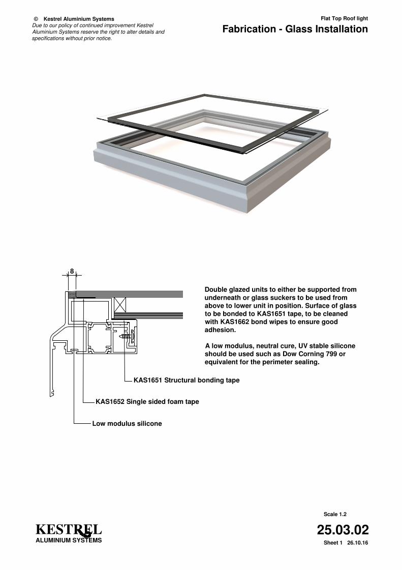
8
KESTRELALUMINIUM SYSTEMS
Scale 1.2
Sheet 1
25.03.02
© Kestrel Aluminium Systems Flat Top Roof light
Fabrication - Glass Installation
26.10.16
Due to our policy of continued improvement Kestrel
Aluminium Systems reserve the right to alter details and specifications without prior notice.
Double glazed units to either be supported from
underneath or glass suckers to be used from
above to lower unit in position. Surface of glass
to be bonded to KAS1651 tape, to be cleaned
with KAS1662 bond wipes to ensure good
adhesion.
A low modulus, neutral cure, UV stable silicone
should be used such as Dow Corning 799 or
equivalent for the perimeter sealing.
KAS1651 Structural bonding tape
KAS1652 Single sided foam tape
Low modulus silicone