manual ati
DESCRIPTION
Robotic Tool ChangerTRANSCRIPT

Engineered Products for Robotic Productivity Pinnacle Park • 1031 Goodworth Drive • Apex, NC 27539 • Tel: 919.772.0115 • Fax: 919.772.8259 • www.ati-ia.com • Email: [email protected]
Quick-Change QC-310
Robotic Tool Changer
(Application-Specific Drawing Available Upon Request)
Installation and Operation Manual
Includes:
Part Number Description
9121-310AM-0-0-0-0 Tool Changer—Master
9121-310DT-0-0-0-0 Tool Changer—Tool
9121-Jxx-M Air/Valve/Mounting Adapter Assembly
9121-DB10-M/T Control & Signal Module—Master & Tool
9121-AB2-M/ABx-T Air Module—Master & Tool Some 3-D Model Downloads are available on our website. Contact your Account Representative for more information.
Manual #: 9610-20-1855

Quick-Change Installation and Operation Manual Document #9620-20-a-general toc and introduction-06
Pinnacle Park • 1031 Goodworth Drive • Apex, NC 27539 • Tel: 919.772.0115 • Fax: 919.772.8259 • www.ati-ia.com • Email: [email protected]
A - 1
A. Introduction ..................................................................................................................2
1.1. Glossary of Terms ..........................................................................................3
1.2. Safety..............................................................................................................4
1.1.1. General ........................................................................................................ 4
1.1.2. Explanation of Warnings ............................................................................... 4
1.1.3. Precautions .................................................................................................. 5
1.3. Product Overview ...........................................................................................6
1.4. Terms and Conditions of Sale .........................................................................7
B. Base Tool Changer
C. Control and Signal Module
D. Fluid Air Modules
E. Electrical Modules
F. High Power Modules
G. Interface Plates
H. Other

Quick-Change Installation and Operation Manual Document #9620-20-a-general toc and introduction-06
Pinnacle Park • 1031 Goodworth Drive • Apex, NC 27539 • Tel: 919.772.0115 • Fax: 919.772.8259 • www.ati-ia.com • Email: [email protected]
A - 2
A. Introduction
Information contained in this document is the property of ATI Industrial Automation, Inc. (ATI) and shall not be reproduced in whole or in part without prior written approval of ATI. The information herein is subject to change without notice. This manual is periodically revised to reflect and incorporate changes made to the product.
The information contained herein is confidential and reserved exclusively for the customers and authorized agents of ATI Industrial Automation and may not be divulged to any third party without prior written consent from ATI. No warranty including implied warranties is made with regard to accuracy of this document or fitness of this device for a particular application. ATI Industrial Automation shall not be liable for any errors contained in this document or for any incidental or consequential damages caused thereby. ATI Industrial Automation also reserves the right to make changes to this manual at any time without prior notice.
ATI assumes no responsibility for any errors or omissions in this document. Users’ critical evaluation of this document is welcomed.
Copyright by ATI Industrial Automation. All rights reserved.
How to Reach Us
Sales, Service and Information about ATI products: ATI Industrial Automation 1031 Goodworth Drive Apex, NC 27539 USA www.ati-ia.com Tel: 919.772.0115 Fax: 919.772.8259 E-mail: [email protected] Technical support and questions: Application Engineering Tel: 919.772.0115 Fax: 919.772.8259 E-mail: [email protected]
CAUTION: This manual describes the function, application, and safety considerations of this product. This manual must be read and understood before any attempt is made to install or operate the product, otherwise damage to the product or unsafe conditions may occur.
!

Quick-Change Installation and Operation Manual Document #9620-20-a-general toc and introduction-06
Pinnacle Park • 1031 Goodworth Drive • Apex, NC 27539 • Tel: 919.772.0115 • Fax: 919.772.8259 • www.ati-ia.com • Email: [email protected]
A - 3
1.1. Glossary of Terms
Term Definition
Bearing Race Hardened steel ring in the Tool plate that is engaged by the locking balls during the locking process.
Cam Circular disc attached to the piston that forces the locking balls outward during the locking process.
Cover Plate Simple, blank closure plate on standard Quick-Change Master assemblies which closes the pneumatic chamber.
Detection Shaft Threaded stem inserted into the back side (top) of the Piston, functions as a target to actuate the Lock/Unlock switches.
EIP End-effector Interface Plate – interface plate between the Tool plate and the customer’s end-effector (tooling).
Electrical Module Any of a wide variety of modules that pass electrical power or signals through the Master to the Tool and to the end-effector.
End-effector Tool used by the robot to perform a particular function.
Lock Port Pneumatic port on the Master plate to which air is supplied to Lock the Master plate to the Tool plate.
L/U Lock/Unlock sensing capability allows the customer to determine the state of the master assembly locking mechanism.
Master Plate The half of the Tool Changer that is mounted to a robot. The Master plate contains the locking mechanism.
No-Touch™ Design feature of all ATI Quick-Change products that allows coupling the Master plate and Tool plate without physical contact prior to locking.
Piston The piston located in the Master plate that actuates the locking mechanism.
Pneumatic Module Any of a wide variety of modules that pass pneumatic power through the Master plate to the Tool plate and to the end-effector.
RIP Robot Interface Plate – interface plate between the robot flange and Master plate.
SIP Sensor Interface Plate used to adapt the Master plate to the robot flange. The SIP is essentially a Robot Interface Plate that contains sensors that determine the state (locked/unlocked/no tool) of the Master plate.
Sensor Plate Cover plate for the back side of the Master plate, seals the pneumatic chamber and provides mounting points for the Lock/Unlock switches.
Tool Plate The half of the Tool Changer to which various tools or end-effectors are mounted.
Tool Stand Stand that holds tools not being used by the robot. This is usually supplied by the customer and is specific to the application.
Unlock Port Pneumatic port on the Master plate to which air is supplied to Unlock the Master plate from the Tool plate.
Quick-Change Installation and Operation Manual Document #9620-20-a-general toc and introduction-06
Pinnacle Park • 1031 Goodworth Drive • Apex, NC 27539 • Tel: 919.772.0115 • Fax: 919.772.8259 • www.ati-ia.com • Email: [email protected]
A - 4
1.2. Safety
1.1.1. General
Prior to purchase and installation, the customer should verify that the Tool Changer selected is rated for the maximum loads and moments expected during operation. Refer to product specifications in Section 7 of each module of this manual or contact ATI for assistance. Particular attention should be paid to dynamic loads caused by robot acceleration and deceleration. These forces can be many times the value of static forces in high acceleration or deceleration situations.
The customer is responsible for ensuring that the area between the Master and Tool sides is clear of foreign objects during mating and subsequent coupling. Failure to do so may result in serious injury to personnel.
The customer is responsible for understanding the function of the Tool Changer and implementing the proper hardware and/or software to operate the Tool Changer safely. The Tool Changer should be controlled such that there is no chance of locking or unlocking in a position that would endanger personnel and/or equipment. If the Tool Changer is specified with Lock/Unlock (L/U) and Ready-to-Lock (RTL) sensing capability, the status should be monitored and proper interlocks applied to prevent injury to personnel and equipment.
All pneumatic fittings and tubing must be capable of withstanding the repetitive motions of the application without failing. The routing of electrical and pneumatic lines must minimize the possibility of stress/strain, kinking, rupture, etc. Failure of critical electrical or pneumatic lines to function properly may result in injury to personnel and equipment.
All electrical power, pneumatic and fluid circuits should be disconnected during servicing.
1.1.2. Explanation of Warnings
The warnings included here are specific to the product(s) covered by this manual. It is expected that the user heed all warnings from the robot manufacturer and/or the manufacturers of other components used in the installation.
Danger indicates that a situation could result in potentially serious injury or damage to equipment.
Caution indicates that a situation could result in damage to the product and/or the other system components. !
DANGER: The gap between the Master and Tool sides is a pinch point. All personnel should be prevented from placing any part of their body or clothing in the gap, especially during actuation of the locking mechanism.
Quick-Change Installation and Operation Manual Document #9620-20-a-general toc and introduction-06
Pinnacle Park • 1031 Goodworth Drive • Apex, NC 27539 • Tel: 919.772.0115 • Fax: 919.772.8259 • www.ati-ia.com • Email: [email protected]
A - 5
1.1.3. Precautions
DANGER: During operation, the area between the Master and Tool must be kept clear.
DANGER: Power and air should always be removed prior to maintenance or repair.
CAUTION: The Quick-Change system must not be actuated without being mounted to the robot interface plate. Damage to the cover plate and O-ring may result. !
CAUTION: The Quick-Change system is only to be used for intended applications and applications approved by the manufacturer. !
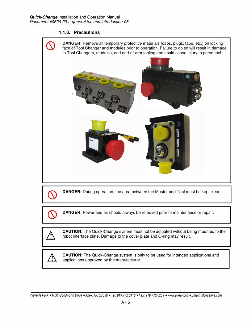
DANGER: Remove all temporary protective materials (caps, plugs, tape, etc.) on locking face of Tool Changer and modules prior to operation. Failure to do so will result in damage to Tool Changers, modules, and end-of-arm tooling and could cause injury to personnel.
Quick-Change Installation and Operation Manual Document #9620-20-a-general toc and introduction-06
Pinnacle Park • 1031 Goodworth Drive • Apex, NC 27539 • Tel: 919.772.0115 • Fax: 919.772.8259 • www.ati-ia.com • Email: [email protected]
A - 6
1.3. Product Overview
A Tool Changer enhances the flexibility and reliability of a robotic cell. Robotic Tool Changers are used in automated Tool change applications as well as manual Tool change operations. Robotic Tool Changers also provide a method for quick Tool change for maintenance purposes.
The Quick-Change robotic Tool Changer has been designed to incorporate high strength in a small, low-weight package. The Tool change system consists of two primary parts: the Master plate and the Tool plate. The Master plate is mounted to a robot while the customer supplied end-effector is typically attached to the Tool plate. The Master plate is typically mounted to the robot with an optional interface plate (SIP or RIP).
The optional Sensor Interface Plate (SIP) plate may also be used for detecting the lock condition of the Tool Changer and/or Tool plate presence. The use of a SIP is highly recommended for achieving the highest level of safety and reliability
In operation, the robot can be programmed to select the desired end-effector by coupling the Master plate to the Tool plate. Electrical signals, pneumatic power and fluids can be transferred to the end-effector(s) through the Master plate and Tool plate by optional modules and ports. See the respective manuals for these options for more details on their operation.
The ATI Tool Changer has been designed to provide extremely long life with little maintenance.

Quick-Change Installation and Operation Manual Document #9620-20-a-general toc and introduction-06
Pinnacle Park • 1031 Goodworth Drive • Apex, NC 27539 • Tel: 919.772.0115 • Fax: 919.772.8259 • www.ati-ia.com • Email: [email protected]
A - 7
1.4. Terms and Conditions of Sale
The following Terms and Conditions are a supplement to and include a portion of ATI’s Standard Terms and Conditions, which are on file at ATI and available upon request.
ATI warrants to Purchaser that robotic Tool Changer products purchased hereunder will be free from defects in material and workmanship under normal use for a period of three (3) years from the date of shipment. This warranty does not cover components subject to wear and tear under normal usage or those requiring periodic replacement. ATI will have no liability under this warranty unless: (a) ATI is given written notice of the claimed defect and a description thereof within thirty (30) days after Purchaser discovers the defect and in any event not later than the last day of the warranty period; and (b) the defective item is received by ATI not later ten (10) days after the last day of the warranty period. ATI’s entire liability and Purchaser’s sole remedy under this warranty is limited to repair or replacement, at ATI’s election, of the defective part or item or, at ATI’s election, refund of the price paid for the item. The foregoing warranty does not apply to any defect or failure resulting from improper installation, operation, maintenance or repair by anyone other than ATI.
ATI will in no event be liable for incidental, consequential or special damages of any kind, even if ATI has been advised of the possibility of such damages. ATI’s aggregate liability will in no event exceed the amount paid by purchaser for the item which is the subject of claim or dispute. ATI will have no liability of any kind for failure of any equipment or other items not supplied by ATI.
No action against ATI, regardless of form, arising out of or in any way connected with products or services supplied hereunder may be brought more than one (1) year after the cause of action accrued.
No representation or agreement varying or extending the warranty and limitation of remedy provisions contained herein is authorized by ATI, and may not be relied upon as having been authorized by ATI, unless in writing and signed by an executive officer of ATI.
Unless otherwise agreed in writing by ATI, all designs, drawings, data, inventions, software and other technology made or developed by ATI in the course of providing products and services hereunder, and all rights therein under any patent, copyright or other law protecting intellectual property, shall be and remain ATI’s property. The sale of products or services hereunder does not convey any express or implied license under any patent, copyright or other intellectual property right owned or controlled by ATI, whether relating to the products sold or any other matter, except for the license expressly granted below.
In the course of supplying products and services hereunder, ATI may provide or disclose to Purchaser confidential and proprietary information of ATI relating to the design, operation or other aspects of ATI’s products. As between ATI and Purchaser, ownership of such information, including without limitation any computer software provided to Purchaser by ATI, shall remain in ATI and such information is licensed to Purchaser only for Purchaser’s use in operating the products supplied by ATI hereunder in Purchaser’s internal business operations.
Without ATI’s prior written permission, Purchaser will not use such information for any other purpose or provide or otherwise make such information available to any third party. Purchaser agrees to take all reasonable precautions to prevent any unauthorized use or disclosure of such information.
Purchaser will not be liable hereunder with respect to disclosure or use of information which: (a) is in the public domain when received from ATI; (b) is thereafter published or otherwise enters the public domain through no fault of Purchaser; (c) is in Purchaser’s possession prior to receipt from ATI; (d) is lawfully obtained by Purchaser from a third party entitled to disclose it; or (f) is required to be disclosed by judicial order or other governmental authority, provided that, with respect to such required disclosures, Purchaser gives ATI prior notice thereof and uses all legally available means to maintain the confidentiality of such information.

Quick-Change Installation and Operation Manual Document #9620-20-B-310 Series Base Tool Changer-16
Pinnacle Park • 1031 Goodworth Drive • Apex, NC 27539 • Tel: 919.772.0115 • Fax: 919.772.8259 • www.ati-ia.com • Email: [email protected]
B - 1
Table of Contents
B. Base Tool Changer ...................................................................................................................2 QC-310 Series—Robotic Tool Changer .......................................................................................2 1. Product Overview.................................................................................................................2
1.1 Master Plate Assembly ................................................................................................................. 2 1.2 Tool Plate Assembly ..................................................................................................................... 3 1.3 Optional Modules .......................................................................................................................... 3
2. Installation ............................................................................................................................4 2.1 Master Interface ............................................................................................................................ 5 2.2 Tool Interface ................................................................................................................................ 5 2.3 Tool Stand Design......................................................................................................................... 6
2.3.1 Tool Locating Features................................................................................................. 7 2.3.2 Tool Stand Sensors ...................................................................................................... 8
2.4 Pneumatic and Electrical Connections ......................................................................................... 8 3. Operation ..............................................................................................................................8
3.1 Coupling Sequence....................................................................................................................... 8 3.2 Fail-Safe Operation ....................................................................................................................... 9 3.3 Uncoupling .................................................................................................................................. 10
4. Maintenance .......................................................................................................................10 4.1 Preventive Maintenance.............................................................................................................. 10 4.2 Cleaning, Lubrication, Adjustment and Replacement................................................................. 12
4.2.1 Cleaning and Lubrication of the Locking Mechanism and Alignment Pins (Master Plate). ............................................................................................................ 12
4.2.2 Cleaning the Locking Mechanism and Alignment Pin Bushings (Tool Plate). ........... 13 4.2.3 Lock/Unlock Sensor Assembly Replacement (Units using a dual-sensor
assembly) See Figure 4.1. ......................................................................................... 13 4.2.4 Unlock sensor adjustment and replacement (Units with the Unlock sensor
mounted directly in body). See Fig. 4.2...................................................................... 14 4.2.5 Lock Sensor Assembly Replacement (Units with the Lock sensor Assembly).
See Fig. 4.2. ............................................................................................................... 15 4.2.6 Lock/Unlock Sensor Adjustment and Replacement (Units using individual
sensors). See Fig. 4.3 ................................................................................................ 16 4.2.7 RTL Sensor Replacement. See Fig. 4.4..................................................................... 17 4.2.8 Alignment Pin Replacement (7/8” Two Piece Pin Sub-Assembly)............................. 17
5. Troubleshooting.................................................................................................................18 6. Recommended Spare Parts ..............................................................................................19 7. Specifications.....................................................................................................................20 8. Drawings .............................................................................................................................21

Quick-Change Installation and Operation Manual Document #9620-20-B-310 Series Base Tool Changer-16
Pinnacle Park • 1031 Goodworth Drive • Apex, NC 27539 • Tel: 919.772.0115 • Fax: 919.772.8259 • www.ati-ia.com • Email: [email protected]
B - 2
B. Base Tool Changer
QC-310 Series—Robotic Tool Changer 1. Product Overview
1.1 Master Plate Assembly The Master base assembly includes an anodized aluminum body, a hardened stainless-steel locking mechanism, and hardened steel alignment pins (see Figure 3.1).
The body or Master plate has (4) flat sides for mounting of optional modules. Flat ‘A’ is dedicated for mounting of the control/signal module along with tool changer supply air that is provided through an air or valve adapter. Flats ‘B’, ‘C’, and ‘D’ are fully interchangeable and optional modules can be arranged to suit the application or robot dress, as required.
The locking mechanism consists of a cylindrical housing with holes that retain hardened chrome-steel balls. Tapered pins located on the Master body mate with holes in the Tool body to ensure repeatable alignment during the coupling process. An extreme pressure grease is applied to the cam, male coupling, ball bearings and pins to enhance performance and maximize life of the components.
A dual-sensor assembly is mounted into the body of the Master plate to verify the lock/unlock position of the piston and cam. The sensors provide the lock and unlock (L/U) signals through the control/signal module.
Two proximity sensors are designed into the body of the Master plate to verify Tool plate presence when coupled. The sensors provide a ready-to-lock (RTL) signal through the control/signal module.
Figure 1.1—Master Plate Assembly
Lock/Unlock Air Supplied Thru Air/Valve Adapter Mounted to Flat A
Cable Retaining Tabs
(3) Common Ledge Mounting Feature
Prox Sensor (RTL Signal)
(2) Tapered Alignment Pin
(9) Ball Bearing
Cam
Male Coupling
Prox Sensor (RTL Signal)
Internal Prox Sensors (Lock/Unlock) [Not visible]
Quick-Change Installation and Operation Manual Document #9620-20-B-310 Series Base Tool Changer-16
Pinnacle Park • 1031 Goodworth Drive • Apex, NC 27539 • Tel: 919.772.0115 • Fax: 919.772.8259 • www.ati-ia.com • Email: [email protected]
B - 3
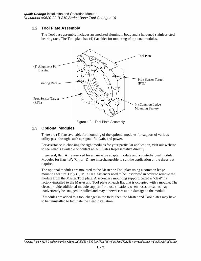
1.2 Tool Plate Assembly The Tool base assembly includes an anodized aluminum body and a hardened stainless-steel bearing race. The Tool plate has (4) flat sides for mounting of optional modules.
Figure 1.2—Tool Plate Assembly
1.3 Optional Modules There are (4) flats available for mounting of the optional modules for support of various utility pass-through, such as signal, fluid/air, and power.
For assistance in choosing the right modules for your particular application, visit our website to see what is available or contact an ATI Sales Representative directly.
In general, flat ‘A’ is reserved for an air/valve adapter module and a control/signal module. Modules for flats ‘B’, ‘C’, or ‘D’ are interchangeable to suit the application or the dress-out required.
The optional modules are mounted to the Master or Tool plate using a common ledge mounting feature. Only (2) M6 SHCS fasteners need to be unscrewed in order to remove the module from the Master/Tool plate. A secondary mounting support, called a “cleat”, is factory-installed to the Master and Tool plate on each flat that is occupied with a module. The cleats provide additional module support for those situations when hoses or cables may inadvertently be snagged or pulled and may otherwise result in damage to the module.
If modules are added to a tool changer in the field, then the Master and Tool plates may have to be uninstalled to facilitate the cleat installation.
Prox Sensor Target (RTL) (4) Common Ledge
Mounting Feature
Tool Plate
Prox Sensor Target (RTL)
(2) Alignment Pin Bushing
Bearing Race

Quick-Change Installation and Operation Manual Document #9620-20-B-310 Series Base Tool Changer-16
Pinnacle Park • 1031 Goodworth Drive • Apex, NC 27539 • Tel: 919.772.0115 • Fax: 919.772.8259 • www.ati-ia.com • Email: [email protected]
B - 4
2. Installation All fasteners used to mount the tool changer to the robot and to user Tools should be tightened to a torque value as indicated below. Furthermore, removable (blue) Loctite 242 must be used on these fasteners.
Mounting conditions Fastener Size and Property Class
Recommended Torque
Master Plate to Robot Interface Plate (6061-T6 aluminum)
Minimum thread engagement of 24mm (0.94”) [1.5X fastener Ø].
M16-2.0
Class 12.9
225 N-m
(165 ft-lbs.)
Master Plate to Robot Interface Plate (6061-T6 aluminum)
Minimum thread engagement of 18mm (0.71”) [1.5X fastener Ø].
M12-1.75
Class 12.9
95 N-m
(70 ft-lbs.)
Master Plate to Robot (steel; USS ≥ 90KSI)
Minimum thread engagement of 16mm (0.63”) [1.0X fastener Ø].
M16-2.0
Class 12.9
225 N-m
(165 ft-lbs.)
Master Plate to Robot (steel; USS ≥ 90KSI)
Minimum thread engagement of 12mm (0.47”) [1.0X fastener Ø].
M12-1.75
Class 12.9
95 N-m
(70 ft-lbs.)
End-effector Interface Plate (aluminum) to Tool Plate (7075-T6 aluminum)
Thread engagement of 21mm (0.83”) [1.3X fastener Ø].
M16-2.0
Class 12.9
225 N-m
(165 ft-lbs.)
End-effector Interface Plate (aluminum) to Tool Plate (7075-T6 aluminum)
Minimum thread engagement of 18mm (0.71”) [1.5X fastener Ø].
M12-1.75
Class 12.9
94 N-m
(70 ft-lbs.)
End-effector Interface Plate (aluminum) to Tool Plate (7075-T6 aluminum)
Minimum thread engagement of 15mm (0.59”) [1.5X fastener Ø].
M10-1.5
Class 12.9
52 N-m
(38 ft-lbs.)
Tool Plate to End-effector Interface Plate (6061-T6 aluminum)
Minimum thread engagement of 15mm (0.59”) [1.5X fastener Ø].
M10-1.5
Class 12.9
52 N-m
(38 ft-lbs.)
CAUTION: Care should be taken to select fasteners for mounting that are not too long, such that a gap is formed at the interface. !
Quick-Change Installation and Operation Manual Document #9620-20-B-310 Series Base Tool Changer-16
Pinnacle Park • 1031 Goodworth Drive • Apex, NC 27539 • Tel: 919.772.0115 • Fax: 919.772.8259 • www.ati-ia.com • Email: [email protected]
B - 5
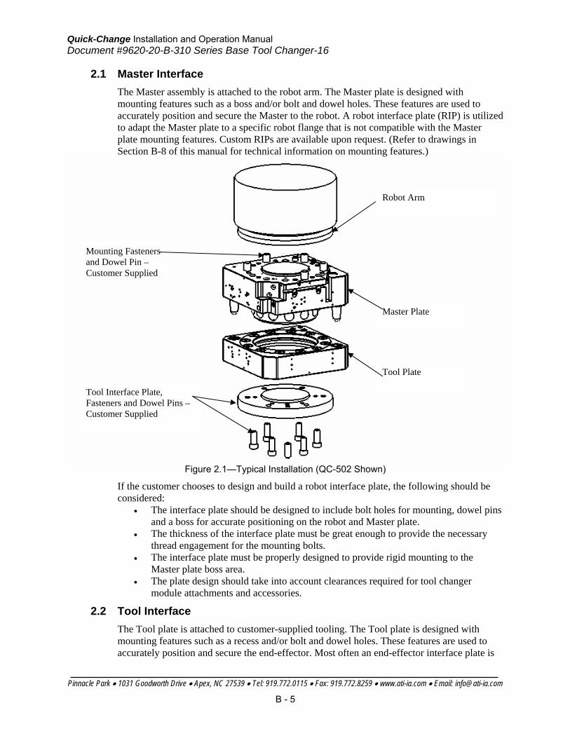
2.1 Master Interface The Master assembly is attached to the robot arm. The Master plate is designed with mounting features such as a boss and/or bolt and dowel holes. These features are used to accurately position and secure the Master to the robot. A robot interface plate (RIP) is utilized to adapt the Master plate to a specific robot flange that is not compatible with the Master plate mounting features. Custom RIPs are available upon request. (Refer to drawings in Section B-8 of this manual for technical information on mounting features.)
Figure 2.1—Typical Installation (QC-502 Shown)
If the customer chooses to design and build a robot interface plate, the following should be considered:
• The interface plate should be designed to include bolt holes for mounting, dowel pins and a boss for accurate positioning on the robot and Master plate.
• The thickness of the interface plate must be great enough to provide the necessary thread engagement for the mounting bolts.
• The interface plate must be properly designed to provide rigid mounting to the Master plate boss area.
• The plate design should take into account clearances required for tool changer module attachments and accessories.
2.2 Tool Interface The Tool plate is attached to customer-supplied tooling. The Tool plate is designed with mounting features such as a recess and/or bolt and dowel holes. These features are used to accurately position and secure the end-effector. Most often an end-effector interface plate is
Robot Arm
Master Plate
Tool Plate
Mounting Fasteners and Dowel Pin – Customer Supplied
Tool Interface Plate, Fasteners and Dowel Pins – Customer Supplied
Quick-Change Installation and Operation Manual Document #9620-20-B-310 Series Base Tool Changer-16
Pinnacle Park • 1031 Goodworth Drive • Apex, NC 27539 • Tel: 919.772.0115 • Fax: 919.772.8259 • www.ati-ia.com • Email: [email protected]
B - 6
utilized to adapt the Tool plate to an end-effector that is not compatible with the Tool plate mounting features. Custom end-effector interface plates can be supplied by ATI to meet customer requirements (see Figure 2.1) (refer to the application drawing).
When the customer chooses to design and build an end-effector interface plate, the following should be considered:
• The interface plate should be designed to include bolt holes for mounting, dowel pins, and a boss that mates with Tool body recess for accurate positioning.
• When using a locating boss, the race cover must be removed. • The thickness of the interface plate must be great enough to provide the necessary
thread engagement for the mounting bolts. • The plate design should take into account clearances required for tool changer
module attachments and accessories. • The interface plate should be designed with a hole in its center to allow for manually
returning the locking mechanism to the unlocked position under adverse conditions (i.e. unintended loss of power and/or air pressure). The center access hole should be kept small [minimum recommended hole diameter: 25.4mm (1”)] to prevent debris from contaminating the locking mechanism while operating in dirty environments. Even greater protection will result if the center standard race cover with removable access plug is used. [Note: Thru hole diameter in plate: 14.3mm (.563”). Grommet outside diameter: 22.5mm (.88”)].
2.3 Tool Stand Design
In most cases, the Tools are stored in a tool stand when not being used by the robot. During coupling and lock-up, the tool stand must allow for movement (float) in a plane parallel with the mating surfaces of the Master plate and Tool plates (X and Y). Even slight misalignment between the Master plate and Tool plate can generate high forces during lock-up if the Tool plate is not allowed to float into place during lock-up. These high forces can cause excessive wear and even jamming of the end-effector and robot. The degree of float required depends on the accuracy of the robot’s positioning and the repeatability of the Tool location in the tool stand during lock-up. See Figure 2.2 and Table 2.3 for recommended maximum allowable float (offsets) prior to coupling. The tool stand should be designed to minimize misalignment during coupling and uncoupling. In some cases, greater offsets than shown in Table 2.3 can be accommodated by the Master and Tool plates, but will increase wear.
Ideally, the Tool should be hanging vertically in the tool stand so that gravity acts to uncouple the Tool plate from the Master plate during unlocking. It is possible to design tool stands that hold Tools in the horizontal position, but care must be taken that the necessary compliance is provided during coupling and uncoupling. In general, “horizontal-position” tool stands cause more wear on the locking mechanism and locating features of the Tool and tool stand.
CAUTION: Tool stand design is critical to proper operation of the tool changer. Improperly designed tool stands can cause misalignments that will cause jamming and/or excessive wear of tool changer components.
!
CAUTION: During coupling and lock-up the tool stand must allow for movement (float) in a plane parallel to the mating surfaces of the Master plate and Tool plates, and in a direction perpendicular to this plane, towards the Master plate.
!

Quick-Change Installation and Operation Manual Document #9620-20-B-310 Series Base Tool Changer-16
Pinnacle Park • 1031 Goodworth Drive • Apex, NC 27539 • Tel: 919.772.0115 • Fax: 919.772.8259 • www.ati-ia.com • Email: [email protected]
B - 7
Lock-up should occur with the Master plate in the No-Touch™ Locking zone (see Table 2.3), but not touching the Tool plate. As locking occurs, the Master plate should draw the Tool plate into the locked position.
Tool stands may also need to incorporate means for covering Tools and electrical modules to protect them in dirty environments, such as grinding or welding. Alternatively, locating tool stands in areas shielded from weld spatter, fluids, adhesives, or other debris would eliminate the need for tool covers.
Model No-Touch™ Zone Z Offset (Max)*
(mm)
X and Y Offset (Max)† (mm)
Cocking Offset (Max)
(degrees)
Twisting Offset (Max)
(degrees)
QC-310 ±2.5 ±2 ±0.7 ±1
Table 2.3—Maximum Recommended Offsets Prior to Coupling
Notes: * Maximum values shown. Decreasing actual values will minimize wear during
coupling/uncoupling. †Actual allowable values may be higher in some cases but higher offsets will increase wear during
coupling.
2.3.1 Tool Locating Features The Tool must be positively and repeatably located in the tool stand. A variety of methods may be used to accomplish this. Whatever method is chosen, it is important that the required compliance or “float” be built into the locating system. A common method is to use tapered dowel pins in holes. As the Tool plate is lifted during locking, the taper lets the Tool float into its locked position even with small deviations in robot position. Other Tool locating feature methods include balls and detents, dowel pins in notched V-grooves, etc. Please consult ATI for recommendations or assistance with locating feature design for your particular tooling.
Figure 2.2—Offset Definitions X, Y and Z Offset
Cocking Offset (About X and Y)

Quick-Change Installation and Operation Manual Document #9620-20-B-310 Series Base Tool Changer-16
Pinnacle Park • 1031 Goodworth Drive • Apex, NC 27539 • Tel: 919.772.0115 • Fax: 919.772.8259 • www.ati-ia.com • Email: [email protected]
B - 8
Straight cylindrical dowel pins should not be used as they provide too much surface engagement. During coupling and uncoupling the Tool can bind on these pins due to misalignment of the Master and Tool plates. Robot programming and locational repeatability are vital in Tool pick-up and drop-off.
2.3.2 Tool Stand Sensors It is highly suggested that the customer provide a sensor that detects the presence of a properly seated Tool in the tool stand. The sensor may be used prior to coupling to ensure there is a Tool properly seated in the stand. Sensors may also be used as the robot starts to move away after uncoupling. This provides a fail-safe measure in the event that a Tool should become jammed in the stand or if the Tool should fail to release properly from the robot. Proximity sensors should be located so that the sensing face is vertical to prevent metal shavings, weld spatter or other debris from falling on the sensor and creating false readings.
2.4 Pneumatic and Electrical Connections The air supply used for coupling and uncoupling the tool changer should be clean, dry, and non-lubricated. A supply pressure in the range of 60 to 100 psi is acceptable for operation of the locking mechanism, with a setting of 80 psi suggested. The air should be filtered 50 micron or better.
3. Operation The Master locking mechanism is pneumatically-driven to couple and uncouple with the bearing race on the Tool plate. The Master plate utilizes air ports from a signal control module or air supply block to provide lock and unlock pressure to the locking mechanism.
3.1 Coupling Sequence
Position the Master above the Tool and move the Master into locking position. The mating surfaces of the Master and Tool should be parallel and not touching. Make sure that the
CAUTION: The locking mechanism must be in the unlock position when attempting to couple the tool changer. Failure to adhere to this condition may result in damage to the unit and/or the robot.
!
CAUTION: Do not use the tool changer in the fail-safe condition for extended periods of time. Do not transport the tool changer in the fail-safe condition. Possible damage to the locking mechanism could occur.
!
ATTENTION: All tool changers are initially lubricated using MobilGrease® XHP222 Special grease. The end user must apply additional lubricant to the locking mechanism components and alignment pins prior to start of service (See Section 4.2). Tubes of lubricant for this purpose are shipped with every tool changer. Note: MobilGrease® XHP222 Special is a NLGI #2 lithium complex grease with molybdenum disulfide.
CAUTION: Safe, reliable operation of the tool changer is dependent on a continuous supply of compressed air at a pressure of 60 to 100 PSI. Robot motion should be halted if the air supply pressure drops below 60 PSI for any reason.
!

Quick-Change Installation and Operation Manual Document #9620-20-B-310 Series Base Tool Changer-16
Pinnacle Park • 1031 Goodworth Drive • Apex, NC 27539 • Tel: 919.772.0115 • Fax: 919.772.8259 • www.ati-ia.com • Email: [email protected]
B - 9
tapered alignment pins from the Master enter the alignment holes on the Tool. The alignment pins should be relatively concentric with the alignment holes such that they do not rub against the edge.
The locking mechanism allows the Master to “pull up” the Tool with relatively large gaps between the two sides. It is recommended that the mating faces of the Master and Tool not be touching, but be within 0.04” (1 mm) of each other when coupling to minimize stress and wear on the locking mechanism.
RTL (Ready-To-Lock) sensing is built into the tool changer, providing the ability to sense Tool proximity to the Master prior to locking. The mating faces of the Master and Tool must be positioned within approximately 0.055–0.065” (1.40–1.65mm) of each other for the sensors to detect Tool presence. RTL signals are not required to couple the tool changer, but are recommended as a further confirmation of coupling prior to removing the Tool from the tool stand.
Verify that the RTL signals are read as “on” (true).
Turn the Lock command on. Air is supplied to the locking mechanism to couple the tool changer.
A sufficient delay must be programmed between the Lock command being activated and reading the state of the Locked/Unlocked signals, so that the locking process is completed before checking the locked state.
Read the Locked and Unlocked signals.
The Locked signal should read “on” (true) and the Unlocked signal should read “off” (false).
If the locking mechanism has been actuated and both the Locked and Unlocked signals are read as “off” (false), then a “missed tool” condition has occurred (for example, the Tool is not in the stand or is not positioned properly). In this case, an error should be generated and the robot program halted. The situation requires manual inspection to determine the cause of the problem.
The locking mechanism must be in the Unlocked state before another attempt is made to couple or damage could occur to the robot and/or the tool changer.
3.2 Fail-Safe Operation In the event of air supply loss to the locking mechanism, the tool changer will not uncouple. A slight separation between the Master and Tool plates occurs just after air loss, but at this point the locking balls become trapped and cannot move without air pressure being applied to the Unlock port. This feature provides the tool changer with a fail-safe mechanism.
ATI’s patented fail-safe design prevents the Tool plate from being released in the event of air-pressure loss to the Lock port, thereby increasing safety and reliability. Positional accuracy may not be maintained during air loss but will be regained once air pressure is re-established to the Lock port.
CAUTION: No-TouchTM locking technology allows the unit to couple with a separation distance between the Master and Tool. Direct contact of the Master and Tool mating surfaces is not suggested or required just prior to coupling. Contact may result in damage to the unit and/or the robot.
!

Quick-Change Installation and Operation Manual Document #9620-20-B-310 Series Base Tool Changer-16
Pinnacle Park • 1031 Goodworth Drive • Apex, NC 27539 • Tel: 919.772.0115 • Fax: 919.772.8259 • www.ati-ia.com • Email: [email protected]
B - 10
3.3 Uncoupling The tool changer should be positioned in the Tool Stand in the same location as that when coupling took place.
Turn the Lock output off (for double solenoid valve versions).
Issue the Unlock command. Air is supplied to the locking mechanism to uncouple the tool changer.
A sufficient delay must be programmed between Unlock command being activated and reading the state of the Locked/Unlocked signals, so that the locking process is completed before checking the locked state.
Read the Locked and Unlocked signals.
The Unlocked signal should read “on” (true) and the Locked signal should read “off” (false). Any other condition indicates a problem and the robot program should be halted.
Once the Lock and Unlock signals are verified to be in the proper state, the Master plate may be moved away from the Tool plate in the axial direction.
The robot and Master plate can now proceed to another Tool for coupling and subsequent operations.
4. Maintenance
4.1 Preventive Maintenance The tool changer and optional modules are designed to provide a long life with regular maintenance required.
A visual inspection and preventative maintenance schedule is provided in the table below depending upon the application.
Detailed assembly drawings are provided in Section B-8 of this manual.
CAUTION: This tool changer may be equipped with a Tool Stand Interlock (TSI) feature that physically breaks the Unlock solenoid circuit. Use of the TSI will prevent any unwanted Unlock software commands from being recognized until the circuit is made.
!
CAUTION: Do not use the tool changer in the fail-safe condition for extended periods of time. Do not transport the tool changer in the fail-safe condition. Possible damage to the locking mechanism could occur.
!
ATTENTION: The cleanliness of the work environment strongly influences the trouble-free operation of the changer. The dirtier the environment, the greater the need for protection against debris. Protection of the entire EOAT, the master, the tool and all of the modules may be necessary. Protective measures include the following: 1) placement of tools stands away from debris generators, 2) covers incorporated into the tool stands (see Section 2.3) and 3) guards, deflectors, air curtains and similar devices built into the EOAT and the tool stand.

Quick-Change Installation and Operation Manual Document #9620-20-B-310 Series Base Tool Changer-16
Pinnacle Park • 1031 Goodworth Drive • Apex, NC 27539 • Tel: 919.772.0115 • Fax: 919.772.8259 • www.ati-ia.com • Email: [email protected]
B - 11
Application(s) Tool Change Frequency
Inspection Schedule
> 1 per minute Weekly
General Usage Material Handling Docking Station < 1 per minute Monthly
Welding/Servo/
Deburring, Foundry Operations
(Dirty Environments)
All
Weekly
Checklist
Balls/Alignment Pins/Holes/Bearing Race Inspect for lubrication and wear. A NLGI #2, lithium-based grease with molybdenum disulfide additive is suggested for locking mechanism and alignment pin lubrication. Over time, lubricants can become contaminated with process debris. Therefore, it is recommended to thoroughly clean the existing grease and replace with new as needed. See Section 4.2. Excessive alignment pin/bushing wear may be an indication of poor robot position during pickup/drop-off. Adjust robot position as needed. Check tool stand for wear and alignment problems. Wear on the balls/bearing race could be an indication of excessive loading.
Mounting Hardware/Interface Connections Inspect for proper torque and interference or wear, abrasions, cuts of hoses, and electrical cables. Tighten and correct as required.
O-rings/Rubber Bushings Inspect for wear, abrasion, and cuts. Exposed o-rings and rubber bushings may be subject to damage during normal operation. Replace damaged o-rings and rubber bushings as needed.
Electrical Contacts Inspect for wear and abrasion. Exposed contacts may be subject to damage during normal operation. Clear debris from the area of the contacts using compressed air. Do not directly clean contacts as abrasion may occur and the performance of the contact may be compromised.
ATTENTION: All tool changers are initially lubricated using MobilGrease® XHP222 Special grease. The end user must apply additional lubricant to the locking mechanism components and alignment pins prior to start of service (See Section 4.2). Tubes of lubricant for this purpose are shipped with every tool changer. Note: MobilGrease® XHP222 Special is a NLGI #2 lithium complex grease with molybdenum disulfide.

Quick-Change Installation and Operation Manual Document #9620-20-B-310 Series Base Tool Changer-16
Pinnacle Park • 1031 Goodworth Drive • Apex, NC 27539 • Tel: 919.772.0115 • Fax: 919.772.8259 • www.ati-ia.com • Email: [email protected]
B - 12
4.2 Cleaning, Lubrication, Adjustment and Replacement 4.2.1 Cleaning and Lubrication of the Locking Mechanism and Alignment Pins
(Master Plate). 1. The locking mechanism must be in the unlock state before cleaning. 2. Use a clean rag to thoroughly remove the existing lubricant and debris from the
balls, the male coupling, the cam and the alignment pins.
Cleaning balls and outer surfaces of male Cleaning balls, cam and inner surfaces of
coupling. male coupling.
3. Check each ball to make sure it moves freely in the male coupling. Additional cleaning may be necessary to free up any balls that are sticking in place.

Quick-Change Installation and Operation Manual Document #9620-20-B-310 Series Base Tool Changer-16
Pinnacle Park • 1031 Goodworth Drive • Apex, NC 27539 • Tel: 919.772.0115 • Fax: 919.772.8259 • www.ati-ia.com • Email: [email protected]
B - 13
4. Apply a liberal coating of lubricant to the balls, the male coupling (inside and out), and the alignment pins.
4.2.2 Cleaning the Locking Mechanism and Alignment Pin Bushings (Tool Plate). 1. Use a clean rag to thoroughly remove any lubricant and debris from the bearing
race and the bushings. 2. No re-lubrication is necessary on the Tool Plate components.
4.2.3 Lock/Unlock Sensor Assembly Replacement (Units using a dual-sensor assembly) See Figure 4.1. [Lock/Unlock sensor assembly P/N: 9005-20-1331 (PNP)] 1. Unplug the sensor cable connectors from lock and unlock sensors. 2. Remove the two (2) M4 socket head cap screws that secure the assembly to the
Master body. 3. Slide the sensor assembly out and discard.

Quick-Change Installation and Operation Manual Document #9620-20-B-310 Series Base Tool Changer-16
Pinnacle Park • 1031 Goodworth Drive • Apex, NC 27539 • Tel: 919.772.0115 • Fax: 919.772.8259 • www.ati-ia.com • Email: [email protected]
B - 14
Lock/Unlock sensor assembly
Figure 4.1—Lock/Unlock sensor assembly. S/N QM1500 and higher.
4. Apply Loctite 222MS to the M4 socket head cap screws supplied with the new
sensor assembly. 5. Slide the assembly into position and secure it to the Master body by tightening
the M4 screws to 30 in-lb of torque. 6. Re-attach cables. 7. Confirm operation of the Unlock sensor by issuing the Unlock command and
verifying that the LED in the Unlock sensor body is on. 8. Confirm operation of the Lock sensor by issuing the Lock command to lock a
Tool to the Master and verifying that the LED in the Lock sensor body is on.
4.2.4 Unlock sensor adjustment and replacement (Units with the Unlock sensor mounted directly in body). See Fig. 4.2 Note: Do not undertake Unlock sensor adjustment until proper operation of the
sensor has been confirmed. This requires removing the sensor from the Master and testing it separately from the EOAT.
Note: When adjusting the unlock sensor the Master must be separated from the
Tool and in the unlocked condition. 1. Unplug the sensor cable from the Lock sensor. 2. Loosen jam nut with 13mm socket or standard pliers. 3. Turn proximity sensor clockwise until the LED in the sensor body comes on. 4. Turn the proximity sensor clockwise another 1/4 turn (90 degrees).
CAUTION: Over tightening the Unlock proximity sensor or the jam nut will cause severe damage to the Master. !
CAUTION: The Lock/Unlock sensor assembly is precision aligned and permanently assembled at the factory. Do not attempt to disassemble and re-build. Over tightening the proximity sensor or the jam nut will cause severe damage to the Master.
!

Quick-Change Installation and Operation Manual Document #9620-20-B-310 Series Base Tool Changer-16
Pinnacle Park • 1031 Goodworth Drive • Apex, NC 27539 • Tel: 919.772.0115 • Fax: 919.772.8259 • www.ati-ia.com • Email: [email protected]
B - 15
5. Tighten jam nut to 20 in-lb of torque. 6. Confirm operation of the Unlock sensor by issuing the Unlock command and
verifying that the LED in the Unlock sensor body is on.
Unlock sensor Jam nut
Lock sensor assembly
Figure 4.2—Unlock sensor in body and Lock sensor assembly. S/N QM1000 thru QM1499.
4.2.5 Lock Sensor Assembly Replacement (Units with the Lock sensor Assembly). See Fig. 4.2. [Lock Sensor Assembly P/N: 9005-20-1310 (PNP)] Note: It may be necessary to loosen and rotate the jam nut on the Unlock sensor to
allow the Lock sensor assembly to be removed. 1. Unplug the sensor cable from the Lock sensor. 2. Remove the two (2) M3 socket head cap screws that secure the assembly to
the Master body. 3. Slide the sensor assembly out and discard.
4. Apply Loctite 222MS to the new M3 socket head cap screws supplied with the new sensor assembly.
5. Attach the new assembly to the Master body by tightening the M3 screws to 12 in-lb of torque.
6. Re-attach sensor cable. 7. Confirm operation of the Lock sensor by issuing the Lock command to lock a
Tool to the Master and then checking to see that the LED in the Lock sensor body is on.
8. If necessary, re-tighten the jam nut on the Unlock sensor.
CAUTION: The Lock sensor assembly is precision aligned and permanently assembled at the factory. Do not attempt to disassembly and re-built. Over tightening the proximity sensor or the jam nut will cause severe damage to the Master.
!

Quick-Change Installation and Operation Manual Document #9620-20-B-310 Series Base Tool Changer-16
Pinnacle Park • 1031 Goodworth Drive • Apex, NC 27539 • Tel: 919.772.0115 • Fax: 919.772.8259 • www.ati-ia.com • Email: [email protected]
B - 16
Unlock sensor Jam nut
Lock sensor Jam nut
Figure 4.3—Lock and Unlock sensors in body. S/N QM0000 thru QM1000.
4.2.6 Lock/Unlock Sensor Adjustment and Replacement (Units using individual sensors). See Fig. 4.3 Note: Do not undertake this adjustment until proper operation of the sensor has
been confirmed. This requires removing the sensor from the Master and testing it separately from the EOAT.
Note: When adjusting the lock sensor the Master must be locked to the Tool. When adjusting the unlock sensor the Master must be separated from the Tool and in the unlocked condition.
1. Loosen jam nut with 13mm socket or standard pliers. 2. Turn proximity sensor clockwise until the LED in the sensor body comes on. 3. Turn the proximity sensor clockwise another 1/4 turn (90 degrees). 4. Tighten jam nut to 20 in-lb of torque.
CAUTION: Over tightening the proximity sensor or the jam nut will cause severe damage to the Master. !

Quick-Change Installation and Operation Manual Document #9620-20-B-310 Series Base Tool Changer-16
Pinnacle Park • 1031 Goodworth Drive • Apex, NC 27539 • Tel: 919.772.0115 • Fax: 919.772.8259 • www.ati-ia.com • Email: [email protected]
B - 17
RTL Sensor (1 of 2)
Figure 4.4—RTL sensor
4.2.7 RTL Sensor Replacement. See Fig. 4.4 1. Unplug the cable from the RTL sensor. 2. Loosen the jam nut securing the sensor to the master body. 3. Remove the sensor from the master and discard. 4. Screw the new sensor into the master body until the face of the sensor is
flush with the surrounding face of the master body. Use a socket and a torque wrench to tighten the jam nut to 20 in-lbs of torque.
5. Attach the cable to the new RTL sensor. 6. Confirm operation of the new sensor by bringing a metallic object into close
proximity to the face of the sensor and watching for the LED in the body of the sensor to come on.
4.2.8 Alignment Pin Replacement (7/8” Two Piece Pin Sub-Assembly) 1. Unscrew the alignment pin sub-assembly from the master plate using a 4mm
hex key. Note: If for any reason the pin cannot be removed using the hex socket in the tip it may be necessary to remove it by other means such as Vise Grip pliers. Another approach is to use the access hole in the back side of the master plate. In this case a 4mm hex key will be needed.
2. Once the alignment pin has been removed verify that the sub-assembly (pin and set screw) is intact. If the set screw portion of the sub-assembly did not come out it will be necessary to remove it separately using the access hole in the back side of the master plate.
3. Apply Loctite® 242 (or similar thread locking compound) to the M8 set screw in the new alignment pin.
4. Install the alignment pin into the bushing and screw it into place. Apply 60 in-lb of torque to fully tighten it.

Quick-Change Installation and Operation Manual Document #9620-20-B-310 Series Base Tool Changer-16
Pinnacle Park • 1031 Goodworth Drive • Apex, NC 27539 • Tel: 919.772.0115 • Fax: 919.772.8259 • www.ati-ia.com • Email: [email protected]
B - 18
5. Troubleshooting Check these conditions for all symptom prior to troubleshooting:
• Proper pneumatic and electrical connections have been made to the Quick-Change • Air is supplied at a minimum of 60psi (4.1 Bar). • No air or vacuum can be trapped in a de-energized Lock or Unlock Port (pressure must be
vented to atmosphere).
Symptom Cause Resolution
The ball bearings and/or cam are not moving freely in the male coupling.
Clean and lubricate as needed to restore smooth operation (see Section 4 - Maintenance).
The control module is not operating correctly.
Check the troubleshooting section of the manual for the specific module.
The Master and Tool are not within the specified No-Touch zone when attempting to lock.
Check that the Tool is properly seated in the Tool Stand. Re-teach the robot to bring the Master and Tool closer together prior to attempting to lock.
Unit will not lock or unlock
Ready-To-Lock (RTL) sensors not activated indicating Tool is not positioned properly
Check that the Tool is properly seated in the tool stand. Re-teach the robot to bring the Master and Tool closer together prior to attempting to lock. Check that both RTL sensors are not damaged. Replace damaged RTL sensors as necessary. Check all cables for damage and that they are connected properly to the signal control module. Replace damaged cables as necessary.
Lock sensor is damaged. Replace Lock sensor or Sensor Assembly as necessary (see Section 4 - Maintenance).
Unit is locked but Lock signal does not read “on” (true).
Lock sensor is out of position.
Replace the Lock sensor or Sensor Assembly as necessary.
Unlock sensor is damaged. Replace Unlock sensor Or Sensor Assembly as necessary (see Section 4 - Maintenance).
Unit is unlocked but Unlock signal does not read “on” (true).
Unlock sensor is out of position Replace Unlock sensor or Sensor Assembly as necessary.

Quick-Change Installation and Operation Manual Document #9620-20-B-310 Series Base Tool Changer-16
Pinnacle Park • 1031 Goodworth Drive • Apex, NC 27539 • Tel: 919.772.0115 • Fax: 919.772.8259 • www.ati-ia.com • Email: [email protected]
B - 19
6. Recommended Spare Parts
Assembly Part Number Description 9121-310AM-0-0-0-0 Complete QC-310 Master Plate, No Options 9005-20-1141 7/8” Two Piece Alignment Pin 9005-20-1198 Master Cleat Assembly 9005-20-1334 Tool Back Cover Plate for QC-310
Master Plate
9121-310DT-0-0-0-0 Complete QC-310 Tool Plate, No Options 9005-20-1199 Tool Cleat Assembly 4010-000020-01 Grommet Seal
Tool Plate
PNP (-SG) Superseded by PNP with LED Cables (-SL) Below
PNP with LED Cables (-SL) All Sensors / Sensor Assemblies Same as for PNP (-SG) 8590-9909999-34 PNP Proximity Sensor (RTL) 8590-9909999-69 L/UL Cable Straight Snap-On to Right Angle Screw 8590-9909999-70 Pico Cordset; Straight Snap-On to Right Angle Screw
Units Using a Lock/Unlock Sensor Assembly 9005-20-1331 PNP Lock/Unlock Sensor Assembly
Units Using Lock Sensor Assembly and Individual Unlock Sensor 9005-20-1310 PNP Sensor Assembly (Lock) 8590-9909999-34 PNP Proximity Sensor (Unlock)
Units Using individual Lock and Unlock Sensors 8590-9909999-34 PNP Proximity Sensor (Lock & Unlock)
NPN with LED Cables (-SE) 8590-9909999-120 NPN Proximity Sensor (RTL) 8590-9909999-121 NPN L/UL Cable Straight Snap-On to Right Angle Screw 8590-9909999-122 NPN Pico Cordset; Straight Snap-On to Right Angle Screw 9005-20-1627 NPN Lock/Unlock Sensor Assembly
AC (-SC) 9000-20-1077 A/C Proximity Sensor/Cable Assembly (RTL1) 9000-20-1078 A/C Proximity Sensor/Cable Assembly1 (RTL2)
Units Using a Lock/Unlock Sensor Assembly 9005-20-1333 A/C Lock/Unlock Sensor/Cable Assembly
Units Using a Lock Sensor Assembly and Individual Unlock sensor 9005-20-1312 A/C Proximity Sensor/Cable Assembly (Lock) 9000-20-1076 A/C Proximity Sensor/Cable Assembly (Unlock)
Units Using Individual Lock and Unlock Sensors
Sensors / Sensor Assemblies
9000-20-1076 A/C Proximity Sensor/Cable Assembly (Lock & Unlock)
Quick-Change Installation and Operation Manual Document #9620-20-B-310 Series Base Tool Changer-16
Pinnacle Park • 1031 Goodworth Drive • Apex, NC 27539 • Tel: 919.772.0115 • Fax: 919.772.8259 • www.ati-ia.com • Email: [email protected]
B - 20
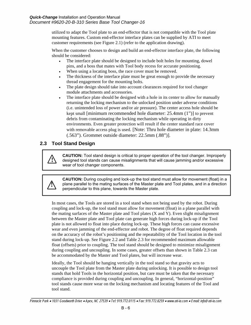
7. Specifications Master and Tool Plates
Suggested Payload Limit 1120 lbs. (500kg) The mass attached to the tool changer.
Operating Temperature Range -20 to 150ºF (-30 to 66ºC)
Operating Pressure Range 60–100psi (4.1–6.9bar)
Locking mechanism supply pressure operating range. Supply to be clean, dry, and filtered to 50 micron or better.
Coupling Force @ 80psi 7940 lbs. (3600 kg)
Axial holding force.
Static Moment Capacity (x, y) 29100 in-lb 3870 (Nm)
Maximum recommended working load for optimum performance of the tool changer.
(z) 28000 in-lb 3164 (Nm)
Torsion
Positional Repeatability 0.0006 in. (0.015mm)
Repeatability tested at rated load at one million cycles.
Weight (coupled, no access.) 45 lbs. (20.4 kg) Master 12.7 kg / Tool 7.7 kg
Max. Recommended distance between Master and Tool Plate
0.10 in. (2.5mm)
No-TouchTM locking technology allows the Master and Tool plates to lock with separation when coupling.
Sensor Information, signal name
L/U (Lock/Unlock)
Internal proximity sensors (2) with quick-disconnect for wiring to the control/signal module to indicate locking mechanism position.
RTL (Ready-To-Lock)
Proximity sensor with quick-disconnect for wiring to control/signal module to indicate Master and Tool mating surfaces within close proximity of each other.
Mounting/Customer Interface
Master Plate Meets ISO 9409-1-A200
Also Supports ABB Super-ISO Pattern
Tool Plate Meets ISO 9409-1-A200
Also Supports (6) Fasteners on ABB Super-ISO Pattern

Quick-Change Installation and Operation Manual Document #9620-20-B-310 Series Base Tool Changer-16
Pinnacle Park • 1031 Goodworth Drive • Apex, NC 27539 • Tel: 919.772.0115 • Fax: 919.772.8259 • www.ati-ia.com • Email: [email protected]
B - 21
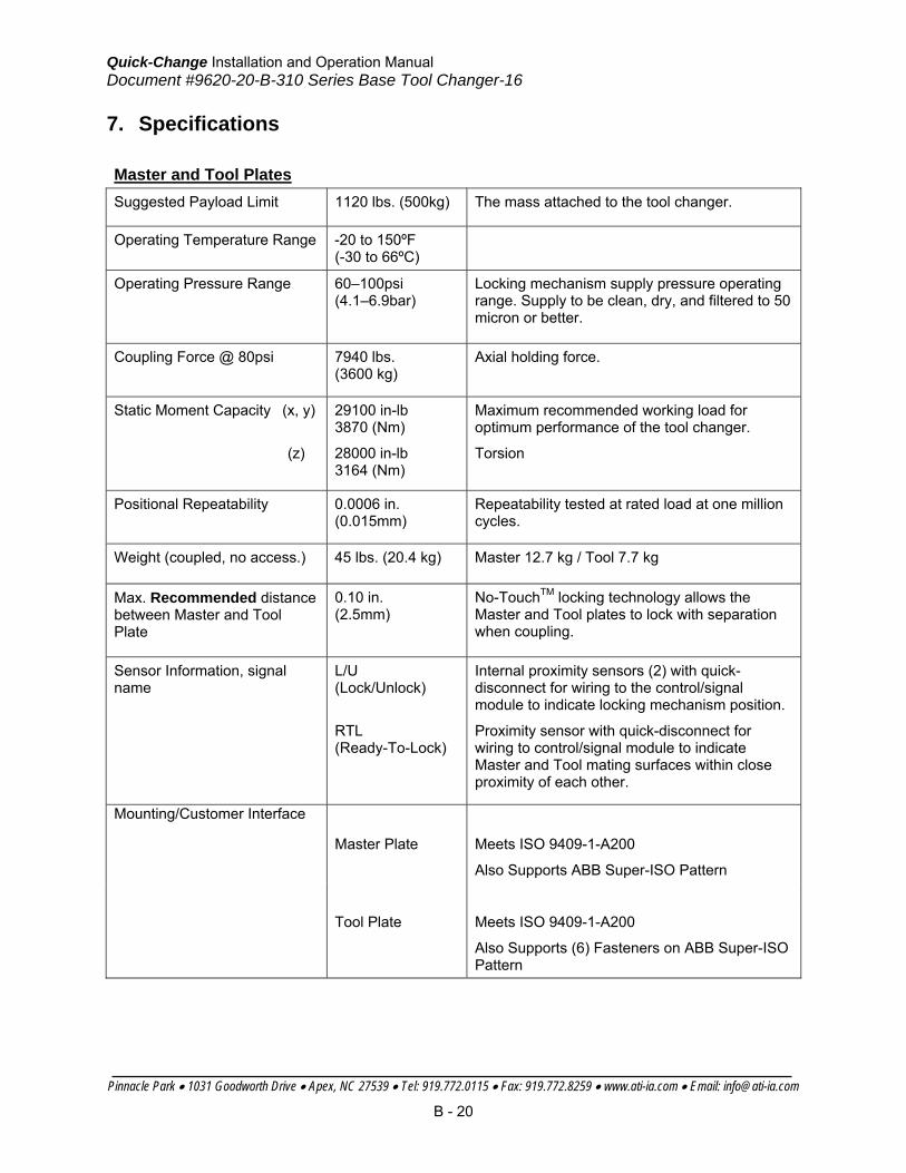
8. Drawings
Quick-Change Installation and Operation Manual Document #9620-20-B-310 Series Base Tool Changer-16
Pinnacle Park • 1031 Goodworth Drive • Apex, NC 27539 • Tel: 919.772.0115 • Fax: 919.772.8259 • www.ati-ia.com • Email: [email protected]
B - 22

Quick-Change Installation and Operation Manual Document #9620-20-B-310 Series Base Tool Changer-16
Pinnacle Park • 1031 Goodworth Drive • Apex, NC 27539 • Tel: 919.772.0115 • Fax: 919.772.8259 • www.ati-ia.com • Email: [email protected]
B - 23

Quick-Change Installation and Operation Manual Document #9620-20-c-db10-04
Pinnacle Park • 1031 Goodworth Drive • Apex, NC 27539 • Tel: 919.772.0115 • Fax: 919.772.8259 • www.ati-ia.com • Email: [email protected]
C - 1
Table of Contents
C. Control and Signal Modules .......................................................................................3
DB10—DeviceNet Module ...............................................................................................3
1. Product Overview .................................................................................................3
1.1 DeviceNet Module .....................................................................................3
2. Installation ............................................................................................................5
2.1 Installing ....................................................................................................5
2.2 Removal ....................................................................................................5
2.3 DeviceNet Configuration............................................................................5
2.4 Utility Schematic ........................................................................................5
3. Product Information ..............................................................................................6
3.1 Master Module Node .................................................................................6 3.1.1 MAC ID ................................................................................................................. 6 3.1.2 Baud Rate ............................................................................................................. 6 3.1.3 Termination Resistor ............................................................................................ 6 3.1.4 Module Status LED ............................................................................................... 7 3.1.5 Network Status LED ............................................................................................. 8
3.2 Arc Prevention Circuit ................................................................................8 3.2.1 Arc Prevention Circuit Behavior During Coupling ................................................. 8 3.2.2 Arc Prevention Circuit Behavior During Uncoupling ............................................. 9
3.3 Tool Module Node ...................................................................................10 3.3.1 MAC ID ............................................................................................................... 10 3.3.2 Baud Rate ........................................................................................................... 10 3.3.3 Termination Resistor .......................................................................................... 10 3.3.4 Tool-ID (Tool Node Only).................................................................................... 11 3.3.5 Module Status LED ............................................................................................. 12 3.3.6 Network Status LED ........................................................................................... 12 3.3.7 Quick Connect .................................................................................................... 12
3.4 Tool-Side TSI ..........................................................................................12 3.4.1 TSI Overview ...................................................................................................... 12
3.5 Software ..................................................................................................15
4. Operation ...........................................................................................................16
5. Maintenance ......................................................................................................16
6. Troubleshooting .................................................................................................17
7. Recommended Spare Parts ...............................................................................17
8. Specifications .....................................................................................................18
9. Drawings ............................................................................................................19
Appendix A ..............................................................................................................21

Quick-Change Installation and Operation Manual Document #9620-20-c-db10-04
Pinnacle Park • 1031 Goodworth Drive • Apex, NC 27539 • Tel: 919.772.0115 • Fax: 919.772.8259 • www.ati-ia.com • Email: [email protected]
C - 2
Glossary of Terms
TERM DEFINITION
Auxiliary Power Available
An input indicating the presence of Auxiliary Power Supply to the ATI Master module.
EOAT End-Of-Arm-Tool (end effector).
Latch The output supplied to the ATI Master DeviceNet node to couple the Tool Changer (only
valid for double solenoid valve equipped units).
Lock A proximity sensor input indicating that the coupling mechanism is in the Lock position.
RTL A proximity sensor input that senses when the ATI Tool is close.
RTL Relay A relay circuit present on the ATI Master module that is triggered by the RTL sensor and
allows the Tool Changer to be uncoupled when there is no Tool present.
RTLV A control reliable input provided for health status monitoring of the RTL Relay.
Solenoid Energized An input indicating current draw from the valve and the solenoid coil.
TSI The Tool Stand Interlock feature is a custom ATI safety solution and circuit designed to only
allow Tool Changer release while in the stand or storage location.
TSI Relay A relay circuit present on the ATI Tool module that is triggered by a tool stand limit switch in
order to close the TSI circuit and allow Tool Changer release.
TSIV A control reliable input supported for monitoring of a tool stand limit switch used with the
TSI circuit.
TSRV A control reliable input provided for health status monitoring of the TSI Relay.
Unlatch The output supplied to the ATI Master DeviceNet node to uncouple the Tool Changer.
Unlock A proximity sensor input indicating that the coupling mechanism is in the Unlock position.

Quick-Change Installation and Operation Manual Document #9620-20-c-db10-04
Pinnacle Park • 1031 Goodworth Drive • Apex, NC 27539 • Tel: 919.772.0115 • Fax: 919.772.8259 • www.ati-ia.com • Email: [email protected]
C - 3
C. Control and Signal Modules
DB10—DeviceNet Module
1. Product Overview
1.1 DeviceNet Module
The DeviceNet modules are required to provide a means for the customer to communicate with and control the Tool Changer. Refer to Section 3 of this manual for detailed DeviceNet programming information and operational capability.
A single or double solenoid valve is provided with the master valve adapter for Lock/Unlock control of the Tool Changer. The user is only required to provide a pneumatic supply source to the Tool Changer.
Power and signal connectors are provided for interfacing on the Master and Tool modules. When the Tool Changer is coupled, the Master and Tool modules pass signals using a spring-loaded pin block. A flexible boot surrounds the pin block to seal the connection from moisture and liquid while coupled.
The DB10 module is designed with special features to afford the user the opportunity to operate the tool changer in the safest manner possible. In addition to providing the standard Lock, Unlock, and Ready-to-Lock sensor inputs, the modules are outfitted with Tool Stand Interlock (TSI). The TSI feature consists primarily of a physical break in the unlatch solenoid valve circuit. The TSI circuit is designed to allow tool changer release ONLY when the tool is in the stand or storage location. Refer to Section 3.4 for more information regarding TSI.
The Tool module employs a series of thumbwheel switches for setting of the Tool-ID input. This allows the customer to distinguish between the different Tools that are being used in a robotic cell or on a production line. See Section 3.5 for DeviceNet bitmap and I/O information.
The DB10 Module also incorporates ATI’s exclusive Arc Prevention Circuit which extends the life of all electrical power contacts by eliminating arcing caused by inductive loads and high inrush current during coupling/uncoupling. Refer to Section 3.2 for additional information regarding the Arc Prevention Circuit.

Quick-Change Installation and Operation Manual Document #9620-20-c-db10-04
Pinnacle Park • 1031 Goodworth Drive • Apex, NC 27539 • Tel: 919.772.0115 • Fax: 919.772.8259 • www.ati-ia.com • Email: [email protected]
C - 4
Figure 1.1—DB10 DeviceNet Module
Lock/Unlock/RTL Sensor Connections (RTL Sensors in Series)
Common Ledge Mounting Feature
TSI Connector
Tool-ID/DIP Switch Located on board In module
Auxiliary Power Connector
Spring-loaded Pin Block And Rubber Seal
Downstream DeviceNet Connector
Downstream Aux. Power Connector
DeviceNet Connector
DB10 Master
DB10 Tool
Master-ID/DIP Switch Located on board In module

Quick-Change Installation and Operation Manual Document #9620-20-c-db10-04
Pinnacle Park • 1031 Goodworth Drive • Apex, NC 27539 • Tel: 919.772.0115 • Fax: 919.772.8259 • www.ati-ia.com • Email: [email protected]
C - 5
2. Installation The control/signal modules are typically installed by ATI prior to shipment. The steps below outline the field installation or removal as required.
2.1 Installing
1. It may be necessary to clean the mounting surface on the Tool Changer prior to installing the module in order to remove any debris that may be present.
2. Typically, proximity sensor and valve cables need to be connected to the Master side control module. These connections need to be made after fastening the module to the Master Plate.
3. Align the module to the holes in the Tool Changer mounting surface using the dowels that are pressed into the module housing. Push the module up flush with the Tool Changer mounting surface.
4. Apply Loctite 242(or similar) thread locker to the socket head cap screws and tighten using a hex key. Avoid over tightening so that the threads are not stripped in the Master/Tool Plates.
2.2 Removal
1. All customer connections up to the module need to be disconnected.
2. Remove the socket head cap screws and pull the module off the Tool Changer.
2.3 DeviceNet Configuration
Various parameters for the DeviceNet modules need to be configured prior to operating the Tool Changer. Please refer to Section 3 of this manual for detailed information on installation and operation of the DeviceNet modules.
2.4 Utility Schematic
Refer to drawings in Section 9 of this manual for customer interface and wiring details for the DB10 modules.
CAUTION: All pneumatic fittings and tubing must be capable of withstanding the repetitive motions of the application without failing. The routing of electrical and pneumatic lines must minimize the possibility of stress pullout, kinking, etc. Failure of some critical electrical and/or pneumatic lines to function properly may result in injury to personnel and equipment.
!
DANGER: Power and air should always be removed prior to maintenance or repair.

Quick-Change Installation and Operation Manual Document #9620-20-c-db10-04
Pinnacle Park • 1031 Goodworth Drive • Apex, NC 27539 • Tel: 919.772.0115 • Fax: 919.772.8259 • www.ati-ia.com • Email: [email protected]
C - 6
3. Product Information The DB10 modules enable the customer to control and communicate with the Tool Changer through a network using standard DeviceNet protocol (www.odva.org). A DeviceNet node is established on the Master module, but not on the Tool. Control of the Tool Changer is realized through the Master Node along with the reporting of various Tool Changer I/O. The Tool module supports Tool-ID reported through the Master and functions as a pass-through for DeviceNet and Auxiliary Power signals to downstream equipment.
The DB10 modules employ standard Mini connectors, 5-pin for DeviceNet communications and power and 4-pin for Auxiliary Power. Please refer to drawings in Section 9 for specific module wiring and connector interface information.
Prior to using the Tool Changer and the DeviceNet modules, various hardware settings must be configured. Communicating with the DeviceNet Modules requires knowledge of DeviceNet standards and operation.
3.1 Master Module Node
The Master Node operates as a Group 2-Only Server on the DeviceNet network. The Master Node supports Explicit Messages, Polled, Strobe and Change of State/Cyclic of the predefined Master/Slave Connection set. The Master Node supports Quick Connect operation as defined by ODVA (refer to the EDS file for specific information). The Master Node does not support the Unconnected Message Manager (UCMM). MAC ID, Baud Rate and Termination Resistor settings for the Master Node are configured through a DIP switch. (2) LED’s provide network and module status. To configure the module and set the DIP switches remove the plastic window and seal as shown in the drawing in Section 9. When replacing the window, ensure that the seal is positioned correctly to prevent fluid leakage.
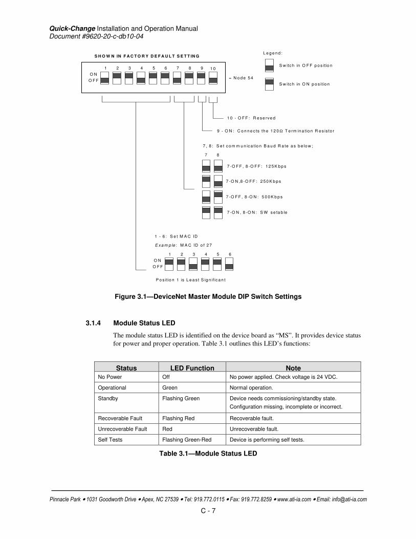
3.1.1 MAC ID
The MAC ID is set by either hardware or software configuration. The range is 0-63. In order for the MAC ID to be set by software, all DIP switch positions must be on. If the MAC ID is set by software, the Baud Rate must also be set by software. Refer to Figure 3.1 for detailed information on DIP switch setup.
3.1.2 Baud Rate
Baud Rate is set by either hardware or software configuration. The possible settings are 125, 250 or 500Kbps. In order for the Baud Rate to be set by software, DIP switch positions 7 and 8 must be on. See Figure 3.1 for DIP switch setup.
3.1.3 Termination Resistor
When DIP switch position 9 is on, a 120Ω resistor is placed across the CAN High and Low lines and termination to the CAN network is provided. If switch 9 is off, termination must be supplied by another device or through a termination cap at the end of the network cable.
Quick-Change Installation and Operation Manual Document #9620-20-c-db10-04
Pinnacle Park • 1031 Goodworth Drive • Apex, NC 27539 • Tel: 919.772.0115 • Fax: 919.772.8259 • www.ati-ia.com • Email: [email protected]
C - 7
S H O W N IN F A C T O R Y D E F A U L T S E T T IN G
1
O N
62 3 4 5 7 8 9
9 - O N : C o n n e c ts th e 1 2 0 Ω T e rm in a tio n R e s is to r
7 8
7 -O F F , 8 -O F F : 1 2 5 K b p s
7 -O N ,8 -O F F : 2 5 0 K b p s
7 -O F F , 8 -O N : 5 0 0 K b p s
7 -O N , 8 -O N : S W s e ta b le
O F F
E xa m p le : M A C ID o f 2 7
1
O N
62 3 4 5
O F F
P o s it io n 1 is L e a s t S ig n if ic a n t
S w itc h in O F F p o s itio n
S w itc h in O N p o s itio n
L e g e n d :
7 , 8 : S e t c o m m u n ic a tio n B a u d R a te a s b e lo w ;
= N o d e 5 4
1 - 6 : S e t M A C ID
1 0
1 0 - O F F : R e se rve d
Figure 3.1—DeviceNet Master Module DIP Switch Settings
3.1.4 Module Status LED
The module status LED is identified on the device board as “MS”. It provides device status for power and proper operation. Table 3.1 outlines this LED’s functions:
Status LED Function Note
No Power Off No power applied. Check voltage is 24 VDC.
Operational Green Normal operation.
Standby Flashing Green Device needs commissioning/standby state.
Configuration missing, incomplete or incorrect.
Recoverable Fault Flashing Red Recoverable fault.
Unrecoverable Fault Red Unrecoverable fault.
Self Tests Flashing Green-Red Device is performing self tests.
Table 3.1—Module Status LED

Quick-Change Installation and Operation Manual Document #9620-20-c-db10-04
Pinnacle Park • 1031 Goodworth Drive • Apex, NC 27539 • Tel: 919.772.0115 • Fax: 919.772.8259 • www.ati-ia.com • Email: [email protected]
C - 8
3.1.5 Network Status LED
The network status LED is identified on the device board as “NS”. It provides network status for power and communication. Table 3.2 outlines this LED’s functions:
Status LED Function Note
No Power/ Off Line Off Device not on line. Check Baud Rate.
Device has not completed the duplicate MAC ID test.
Module Status is On. Check for termination resistor.
Device not powered. See Module Status.
On Line, Not Connected.
Flashing Green Device is on line but connection is not established.
Device not allocated to a master.
OK
On line, Connected
Green Device is on line with connections established.
Device is allocated to a master.
Connection Timeout Flashing Red One or more I/Os are timed out.
Critical Link Failure Red Failed communication. Error detected and incapable of communication.
Duplicate MAC ID or Bus off.
Communication Faulted and Received and Identify Communication Fault Request – Long Protocol Message
Flashing Green-Red A specific Communication Faulted Device. Device has received and accepted an Identify Communication Faulted Request – Long Protocol message.
Table 3.2—Network Status LED
3.2 Arc Prevention Circuit
The DB10 Module incorporates ATI’s exclusive Arc Prevention Circuit. The Arc Prevention Circuit extends the life of all electrical power contacts by eliminating arcing caused by inductive loads and high inrush current during coupling/uncoupling. The Arc Prevention Circuit makes it possible to couple/uncouple without switching power off and prevents damage to the contacts.
In the DB10 Module, the Arc Prevention Circuit controls the ON/OFF status of the following three power signals:
1. Device Net Power (CAN V+)
2. Switched Auxiliary 1 Power V+
3. Unswitched Auxiliary 2 Power V+
The behavior of the Arc circuit is more fully described in the following sections.
3.2.1 Arc Prevention Circuit Behavior During Coupling
The behavior of the Arc Prevention circuit during coupling can be more clearly understood by referring to Figure 3.2, which shows the power-on timing diagram for the Arc Prevention circuit. Starting at the top of the diagram, the LATCH command is issued thus initiating locking of the Master and Tool.
Soon after locking is initiated, electrical contact between Master and Tool Pin Contacts occurs (this time is designated t1 in the diagram). The magnitude of time t1 is a function of

Quick-Change Installation and Operation Manual Document #9620-20-c-db10-04
Pinnacle Park • 1031 Goodworth Drive • Apex, NC 27539 • Tel: 919.772.0115 • Fax: 919.772.8259 • www.ati-ia.com • Email: [email protected]
C - 9
many factors including the weight of the EOAT, the distance between the Master and Tool when the LATCH command is issued, how well the Master and Tool are aligned during pick-up, etc.
As soon as electrical contact is made and the LATCH command is issued, the Arc Prevention Circuit will turn on DeviceNet, Auxiliary 1, and Auxiliary 2 power. The time delay between the electrical contacts becoming fully engaged and when power is actually available to the EOAT (time t2 in the diagram) is less than 100ms.
Important: The Arc Prevention Circuit will only allow power to pass to the Tool after the LATCH command has been issued and the Master and Tool electrical contacts are fully engaged. Loss of the LATCH command after it has been issued does not turn off power to the Tool. It is recommended that the LATCH output command remain true until the LOCKED input goes true and remains true. Only after the coupling operation is complete, should the LATCH command be made false. Refer to the Recommended Sequence of Operation in Appendix A for additional details.
LATCH command
Electrical Contact Between
Master and Tool
DeviceNet, Aux. 1, and
Aux. 2 Power
t1
t2
t1 = Tool Changer Lock Time
t2 = Power Switch ON-delay
ON
OFF
ON
OFF
ON
OFF
Figure 3.2—Arc Circuit Power-On Timing
3.2.2 Arc Prevention Circuit Behavior During Uncoupling
The behavior of the Arc Prevention Circuit during uncoupling can be more clearly understood by referring to Figure 3.3 which shows the power-off timing diagram for the Arc Prevention Circuit. Starting at the top of the diagram, the UNLATCH command is issued thus initiating uncoupling of the Master and Tool.
Immediately after the UNLATCH command is issued, the Arc Prevention Circuit will turn off DeviceNet, Auxiliary 1, and Auxiliary 2 power. The power-off time delay between the UNLATCH command and the switching off of power (designated t3 in the diagram) is less than 50ms.
Some time after power is turned off and the Master and Tool begin to separate, electrical contact between Master and Tool Pin Contacts will be lost. This occurs with a delay, designated t4 in the diagram, after the UNLATCH command is issued. The magnitude of time t4 is a function of many factors, including the weight of the EOAT, the friction between Master and Tool alignment pins, etc. but is usually not shorter than 100ms.

Quick-Change Installation and Operation Manual Document #9620-20-c-db10-04
Pinnacle Park • 1031 Goodworth Drive • Apex, NC 27539 • Tel: 919.772.0115 • Fax: 919.772.8259 • www.ati-ia.com • Email: [email protected]
C - 10
Figure 3.3— Arc Circuit Power-Off Timing
3.3 Tool Module Node
The Tool Node operates as a Group 2-Only Server on the DeviceNet network. The Tool Node supports Explicit Messages, Polled and Strobe of the predefined Master/Slave Connection set. The Tool Node supports Quick Connect operation as defined by ODVA (refer to the EDS file for specific information). The Tool Node does not support the Unconnected Message Manager (UCMM). The MAC ID and Baud Rate settings for the Tool Node are configured through a DIP switch. Tool-ID is set using (5) thumbwheel switches. (2) LED’s provide network and module status. To configure the module and to set the DIP and thumbwheel switches remove the plastic window and seal as shown in the drawing in Section 9. When replacing the window, ensure that the seal is positioned correctly to prevent fluid leakage.
3.3.1 MAC ID
The MAC ID is set by either hardware or software configuration. The range is 0-63. In order for the MAC ID to be set by software, all DIP switch positions must be on. If the MAC ID is set by software, the Baud Rate must also be set by software. Refer to Figure 3.4 for detailed information on DIP switch setup.
3.3.2 Baud Rate
Baud Rate is set by either hardware or software configuration. The possible settings are 125, 250 or 500Kbps. In order for the Baud Rate to be set by software, DIP switch positions 7 and 8 must be on. See Figure 3.4 for DIP switch setup.
3.3.3 Termination Resistor
Internal termination resistance is not supported in the Tool module. Termination must be provided through the Master module or externally as required for proper operation of the network.

Quick-Change Installation and Operation Manual Document #9620-20-c-db10-04
Pinnacle Park • 1031 Goodworth Drive • Apex, NC 27539 • Tel: 919.772.0115 • Fax: 919.772.8259 • www.ati-ia.com • Email: [email protected]
C - 11
1 10
ON
62 3 4 5 7 8 9
10 - OFF: Reserved
7 8
7-OFF, 8 -OFF: 125Kbps
7-ON ,8-OFF: 250Kbps
7-OFF, 8-ON : 500Kbps
7-ON , 8-ON : SW se table
OFF
Example : MAC ID of 19
1
ON
62 3 4 5
OFF
Position 1 is Least S ignifican t B it
Sw itch in OFF position
Sw itch in ON position
Legend:
7 , 8 : Set communication Baud Rate as be low ;
= Node 55
SHOWN IN FACTORY DEFAULT SETTINGSHOWN IN FACTORY DEFAULT SETTINGSHOWN IN FACTORY DEFAULT SETTINGSHOWN IN FACTORY DEFAULT SETTING
1 - 6 : Se t MAC ID
9 - OFF: Reserved
Figure 3.4—DeviceNet Tool Module DIP Switch Settings
3.3.4 Tool-ID (Tool Node Only)
The Tool-ID for a particular tool is established from the setup of (5) thumbwheel switches.
The Tool module is available with switches configured to provide 5 independent (0–9) readings. To set Tool-ID number for each respective end effector remove the plastic window and seal as shown in the drawing in Section 9. When replacing the window, ensure that the seal is positioned correctly to prevent fluid leakage. Refer to Figure 3.5 for detailed information on Tool-ID switch setup.
Figure 3.5—DeviceNet Tool Module Tool-ID Switches
SW5 SW1 Tool ID Switches

Quick-Change Installation and Operation Manual Document #9620-20-c-db10-04
Pinnacle Park • 1031 Goodworth Drive • Apex, NC 27539 • Tel: 919.772.0115 • Fax: 919.772.8259 • www.ati-ia.com • Email: [email protected]
C - 12
3.3.5 Module Status LED
The module status LED (Figure 3.6) is identified on the device board as “MS”. It provides device status for power and proper operation. Refer to Table 3.1 for the module status LED’s functions.
3.3.6 Network Status LED
The network status LED (Figure 3.6) is identified on the device board as “NS”. It provides network status for power and communication. Refer to Table 3.2 for the network status LED’s functions.
3.3.7 Quick Connect
In order to utilize the Quick Connect feature in the tool module, you must enable the feature during commissioning and module replacement. Contact ATI if you need additional help enabling this attribute.
Figure 3.6—Module Status and Network Status LEDs (DB10 Tool)
3.4 Tool-Side TSI
The Tool Stand Interlock (TSI) circuit is provided to ONLY allow Tool release while in the stand or storage location as indicated by actuation of a customer-integrated switch.
A momentary action double-pole, single-throw mechanical limit switch is recommended to be used in concert with TSI. The limit switch, with 2 sets of normally open (NO) contacts, is integrated on the EOAT (see Figure 3.7). An interface to the TSI circuit is made available to the customer via a 4-Pin M12 connector on the Tool module. An off-the-shelf cord set can be utilized to connect this interface to the limit switch assembly.
3.4.1 TSI Overview
The DB10 module relies on the status of the Ready-to-Lock (RTL) sensors and the TSIV input to determine when it is appropriate to unlatch the Tool. The RTL sensors indicate if the Master and Tool are coupled while the TSIV input indicates when the TSI mechanical switch on the Tool is actuated, thereby indicating that the Tool is in the stand. In order to allow the Tool Changer to uncouple when a Tool is not present, a relay circuit (RTL Relay) in parallel
Module LED
Network LED

Quick-Change Installation and Operation Manual Document #9620-20-c-db10-04
Pinnacle Park • 1031 Goodworth Drive • Apex, NC 27539 • Tel: 919.772.0115 • Fax: 919.772.8259 • www.ati-ia.com • Email: [email protected]
C - 13
with the TSI circuit is utilized. The RTL Relay circuit is located in the Master module and is triggered by the RTL sensor. If the RTL sensor is low, indicating no Tool presence, then the RTL Relay circuit is closed allowing the unlatch solenoid valve circuit to be completed and the Tool Changer to be uncoupled. If the RTL sensor is high, indicating Tool presence, then the RTL Relay circuit is open and the TSI circuit is passed through to the Tool side.
Once on the Tool side, the TSI circuit is closed by another relay circuit (TSI Relay). The TSI Relay is located in the Tool module and is triggered by closure of the limit switch. When the EOAT is in the stand and the limit switch is closed, the TSI Relay is closed, thus making the TSI circuit through the tool side. When the EOAT is out of the stand the TSI Relay is open and the TSI circuit remains open regardless of any unintentional Unlatch command.
Control reliability monitoring of the Relays, limit switch and TSI circuit is achieved using the RTLV, TSRV, and TSIV inputs, respectively. Refer to Table 3.3 for suggested fault monitoring conditions.
The DB10 Master module firmware requires that the TSIV input be true in order for the Unlatch output command to be executed when a tool is present (i.e. RTL is high). On the DB10 Tool module, the TSIV input is made available to the customer along with the TSI circuit via the 4-Pin TSI connector. Refer to the TSI connector details in drawings in Section 8 of this manual.
Sensor/Input1 State1 Sensor/Input2 State2 Comment
RTL 0 Tool Module* Present* **RTL Not Operating Properly.
RTL 0 RTLV 1 **RTL Relay or RTL Not Operating Properly.
RTL 1 RTLV 0 RTL Relay or RTL Not Operating Properly.
TSIV 0 TSRV 1 **TSI Relay or Switch Not Operating Properly.
TSIV 1 TSRV 0 TSI Relay or Switch Not Operating Properly.
TSIV 1 Clear of Stand Yes **Switch Failed Closed or Tied Off?
TSRV 1 Clear of Stand Yes TSI Relay Failed Closed?
* Slave Module Present as evidenced by Tool Presence Input or ability to read Tool ID
** Dangerous situation where an unintentional Unlatch command could result in Tool release.
Table 3.3—Fault Monitoring

Quick-Change Installation and Operation Manual Document #9620-20-c-db10-04
Pinnacle Park • 1031 Goodworth Drive • Apex, NC 27539 • Tel: 919.772.0115 • Fax: 919.772.8259 • www.ati-ia.com • Email: [email protected]
C - 14
Figure 3.7—Tool Stand Interlock (TSI)
CAUTION: This tool changer is equipped with Tool Stand Interlock (TSI). Special procedures are required to uncouple the tool changer. !
DB10 Master Module
DB10 Tool Module

Quick-Change Installation and Operation Manual Document #9620-20-c-db10-04
Pinnacle Park • 1031 Goodworth Drive • Apex, NC 27539 • Tel: 919.772.0115 • Fax: 919.772.8259 • www.ati-ia.com • Email: [email protected]
C - 15
3.5 Software
Working EDS files for the Master and Tool nodes are available from our website (www.ati-ia.com/download/edsfiles) or by e-mail, reference the part numbers given below:
DB10-M Node EDS file 9030-20-1009
DB10-T Node EDS file 9030-20-1010
I/O bitmaps for the DeviceNet nodes are provided in the tables below. The default settings are Node 54 for the Master module and Node 55 for the Tool module.
Robot Input From Master DeviceNet Module (Node 54)
Bit # Name Description/Function 0 Lock Tool Changer Lock Prox I/P 1 Unlock Tool Changer Unlock Prox I/P 2 Solenoid Energized Latch/Unlatch Solenoid Energized I/P 3 Auxiliary Power Available Auxiliary Power Present I/P 4 RTL Ready-to-Lock Prox I/P 5 TSIV TSI Switch Verify I/P 6 RTLV RTL Relay Verify I/P 7 TSRV TSI Relay Verify I/P
Table 3.4—I/O Bitmap, Robot Input Node 54 (DB10-M Module)
Robot Output To Master DeviceNet Module (Node 54)
Bit # Name Description/Function 0 Latch ToolChanger Valve Latch O/P
1 Unlatch ToolChanger Valve Unlatch O/P
2 N/A 3 N/A 4 N/A 5 N/A 6 N/A 7 N/A
* Latch O/P only applicable for Double Solenoid Valve Adapter Versions
Table 3.5—I/O Bitmap, Robot Output Node 54 (DB10-M Module)

Quick-Change Installation and Operation Manual Document #9620-20-c-db10-04
Pinnacle Park • 1031 Goodworth Drive • Apex, NC 27539 • Tel: 919.772.0115 • Fax: 919.772.8259 • www.ati-ia.com • Email: [email protected]
C - 16
Robot Input from Tool DeviceNet Module (Node 55)
Bit # Name Description/Function 0 Low Bit Tool-ID Byte 1 N/A
1 N/A
2 N/A
3 N/A
4 SW1 Bit 1
5 SW1 Bit 2
6 SW1 Bit 4
7 High Bit SW1 Bit 8
8 Low Bit Tool-ID Byte 2 SW2 Bit 1
9 SW2 Bit 2
10 SW2 Bit 4
11 SW2 Bit 8
12 SW3 Bit 1
13 SW3 Bit 2
14 SW3 Bit 4
15 High Bit SW3 Bit 8
16 Low Bit Tool-ID Byte 3 SW4 Bit 1
17 SW4 Bit 2
18 SW4 Bit 4
19 SW4 Bit 8
20 SW5 Bit 1
21 SW5 Bit 2
22 SW5 Bit 4
23 High Bit SW5 Bit 8
Table 3.6—I/O Bitmap, Robot Input Node 55 (DB10-T Module)
4. Operation A recommended Sequence of Operations is provided in Appendix A of this manual. This procedure is to be used as a general guide when programming a robot or PLC for use with a Tool Changer and DB10 control/signal modules. This procedure is intended for "automatic" modes used during normal application processes.
5. Maintenance The DeviceNet modules are designed to provide a long life with little maintenance required.
Contact pins on the DeviceNet module should be inspected and cleaned periodically to ensure electrical contact is maintained. Care should be taken not to bend or pull out the contacts when cleaning. Do not use an abrasive media to clean the contact pins as erosion may occur to the contact surface. ATI recommends using a stiff bristle, nylon brush to clean the pins on the master and tool modules, ATI part number 3690-0000064-60.
If the Tool Changer is being used in dirty environments (e.g. welding or deburring applications) care should be taken to limit the exposure of the Tool Changer. Unused Tool assemblies should be covered to prevent debris from settling on the mating surface. Also, the Master assembly should be exposed for only a short period of time during Tool change and down time. In this instance the customer should determine a suitable inspection schedule.
Detailed assembly drawings are provided in Section 9 of this manual.
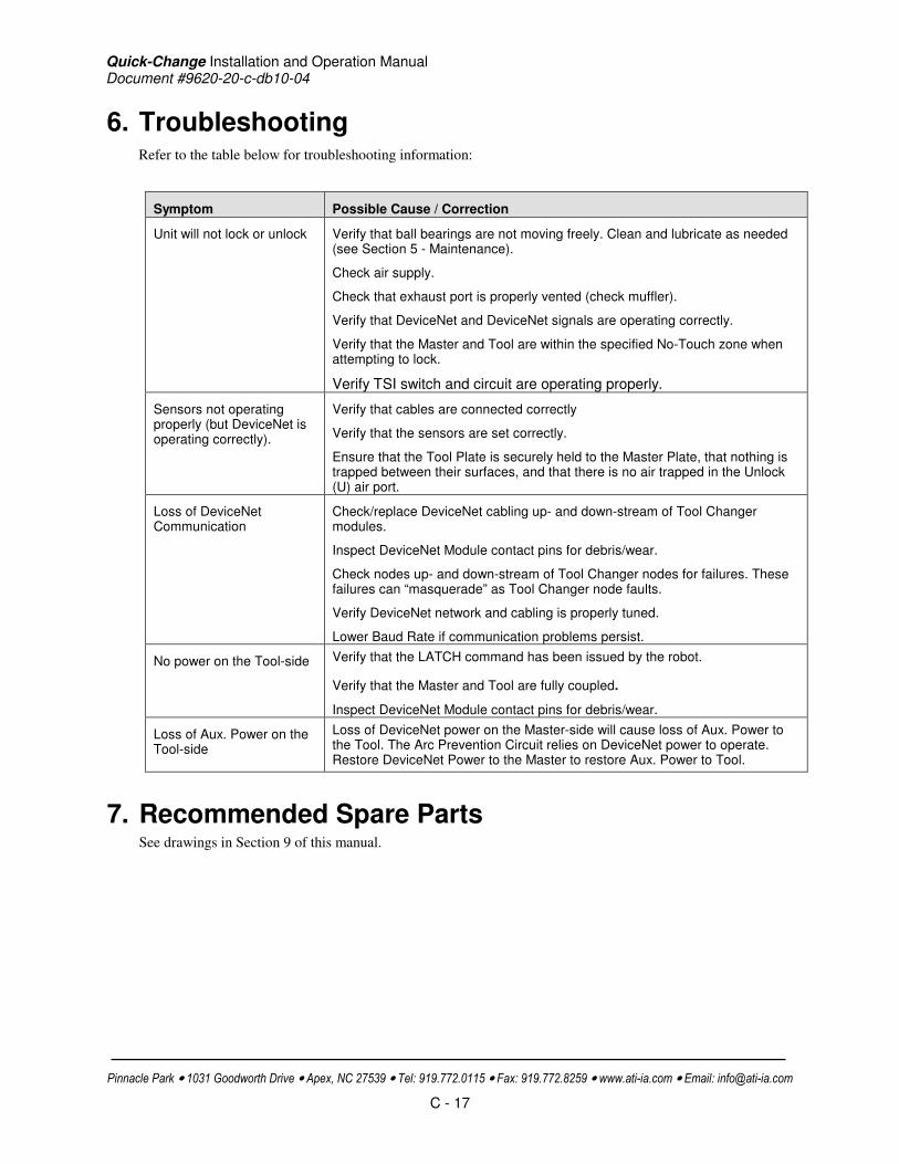
Quick-Change Installation and Operation Manual Document #9620-20-c-db10-04
Pinnacle Park • 1031 Goodworth Drive • Apex, NC 27539 • Tel: 919.772.0115 • Fax: 919.772.8259 • www.ati-ia.com • Email: [email protected]
C - 17
6. Troubleshooting Refer to the table below for troubleshooting information:
Symptom Possible Cause / Correction
Unit will not lock or unlock Verify that ball bearings are not moving freely. Clean and lubricate as needed (see Section 5 - Maintenance).
Check air supply.
Check that exhaust port is properly vented (check muffler).
Verify that DeviceNet and DeviceNet signals are operating correctly.
Verify that the Master and Tool are within the specified No-Touch zone when attempting to lock.
Verify TSI switch and circuit are operating properly.
Sensors not operating properly (but DeviceNet is operating correctly).
Verify that cables are connected correctly
Verify that the sensors are set correctly.
Ensure that the Tool Plate is securely held to the Master Plate, that nothing is trapped between their surfaces, and that there is no air trapped in the Unlock (U) air port.
Loss of DeviceNet Communication
Check/replace DeviceNet cabling up- and down-stream of Tool Changer modules.
Inspect DeviceNet Module contact pins for debris/wear.
Check nodes up- and down-stream of Tool Changer nodes for failures. These failures can “masquerade” as Tool Changer node faults.
Verify DeviceNet network and cabling is properly tuned.
Lower Baud Rate if communication problems persist.
No power on the Tool-side Verify that the LATCH command has been issued by the robot.
Verify that the Master and Tool are fully coupled.
Inspect DeviceNet Module contact pins for debris/wear.
Loss of Aux. Power on the Tool-side
Loss of DeviceNet power on the Master-side will cause loss of Aux. Power to the Tool. The Arc Prevention Circuit relies on DeviceNet power to operate. Restore DeviceNet Power to the Master to restore Aux. Power to Tool.
7. Recommended Spare Parts See drawings in Section 9 of this manual.

Quick-Change Installation and Operation Manual Document #9620-20-c-db10-04
Pinnacle Park • 1031 Goodworth Drive • Apex, NC 27539 • Tel: 919.772.0115 • Fax: 919.772.8259 • www.ati-ia.com • Email: [email protected]
C - 18
8. Specifications
DB10 DeviceNet Master Module
Factory Default Configuration
MAC ID 54, Baud 500 Kbps, termination resistance “on”.
Interface Connections Auxiliary Power: Mini, 4-Pin Male supporting two Auxiliary Power Circuits
DeviceNet: Mini, 5-Pin Male
Integrated Tool Changer I/O:
• 4X M8, 3-pin female connectors supporting Tool Changer Locked, Unlocked, and Ready-to-Lock proximity sensors. RTL sensors are connected in series.
• 3-pin internal pin block used to transmit Latch and Unlatch signals to the solenoid valve.
Electrical Rating Power Pass-Thru:
• Aux1 V+ and Aux2 V+ Power: 5A, 12-30 VDC Note: Arc prevention is applied to Aux1 V+ and Aux2 V+ power.
• CAN V+ (DeviceNet) Power: 5A, 12-30 VDC Note: Arc prevention is applied to CANV+ power.
Signal Pass-Thru: 3 Amp, 30VDC maximum
Tool Changer Control:
• Lock, Unlock, and Ready-to-Lock sensors: 10-30 VDC operational voltage Note: CAN V+ Power provides power to the L, U, and RTL sensors.
• Latch/Unlatch integrated solenoid valve: 21-26 VDC operational voltage Note: Aux1 V+ Power provides power to the Latch/Unlatch solenoid valve.
*Current Draw 183mA @ 24VDC: Master and Tool coupled (Locked, RTL1, and RTL2 sensors “on”, Limit Switches/ TSI Circuits made, i.e.; TSIV1 “on”)
Weight 2.10 lbs (0.95 kg)
DB10 DeviceNet Tool Module
Factory Default Configuration
MAC ID 55, Baud 500Kbps, No termination resistance. (5) Independent Tool ID switches, each reading a (0–9) position (all factory set to Tool Position 1).
Interface Connections Auxiliary Power: Mini, 4-Pin, Female
DeviceNet: Mini, 5-Pin, Female
TSI connectors: M12, 4-Pin, Female
Electrical Rating Power Pass-Thru:
• Aux1 V+ and Aux2 V+ Power: 5A, 12-30 VDC
• CAN V+ (DeviceNet) Power: 5A, 12-30 VDC
Signal Pass-Thru: 3 Amp, 30VDC maximum
*Current Draw 61mA @ 24VDC: Tool Only
Weight 1.35 lbs (0.61 kg)
*Current Draw totals for DeviceNet-powered circuits, not including downstream I/O devices and Auxiliary powered valves. Please refer to the module manufacturer for these specifications.

Quick-Change Installation and Operation Manual Document #9620-20-c-db10-04
Pinnacle Park • 1031 Goodworth Drive • Apex, NC 27539 • Tel: 919.772.0115 • Fax: 919.772.8259 • www.ati-ia.com • Email: [email protected]
C - 19
9. Drawings

Quick-Change Installation and Operation Manual Document #9620-20-c-db10-04
Pinnacle Park • 1031 Goodworth Drive • Apex, NC 27539 • Tel: 919.772.0115 • Fax: 919.772.8259 • www.ati-ia.com • Email: [email protected]
C - 20

Quick-Change Installation and Operation Manual Document #9620-20-c-db10-04
Pinnacle Park • 1031 Goodworth Drive • Apex, NC 27539 • Tel: 919.772.0115 • Fax: 919.772.8259 • www.ati-ia.com • Email: [email protected]
C - 21

Quick-Change Installation and Operation Manual Document #9620-20-c-db10-04
Pinnacle Park • 1031 Goodworth Drive • Apex, NC 27539 • Tel: 919.772.0115 • Fax: 919.772.8259 • www.ati-ia.com • Email: [email protected]
C - 22
Appendix A Recommended Sequence of Operation
1. Start The robot and Tool Changer Master are free of the stand or storage location, the Tool
Changer is uncoupled and the Tool Changer locking mechanism may be fully retracted (Unlocked input true condition) or fully extended (missed Tool condition, i.e., Locked and Unlocked inputs are false). The Tool is by itself in the Tool Stand. a. The RTL input is false. b. RTLV is false. c. The ATI Tool and any downstream device is offline. d. The Auxiliary Power Available input is true provided the Auxiliary Power 1 power
supply is on. e. TSIV is false. f. TSRV is false.
2. Unlock the Master. (This must be done prior to the Master entering the Tool to prevent the ball
bearings from impinging on the Tool bearing race.) a. The Latch output command is made false and the Unlatch output command is made true. b. The Solenoid Energized input is made true. c. The Unlocked input goes true and remains true, indicating that the Tool Changer locking
mechanism is fully retracted and the Unlatch operation is complete. 3. Robot and Master move into the Tool, are parallel and within 0.125” to 0.06” of the Tool (i.e.,
the module contact pins are touching, but the RTL sensors have not yet sensed the targets on the Tool).
4. Robot and Master move within 0.06” of the Tool. a. The TSIV inputs go true, indicating that the Master and Tool are in close proximity of
each other and verifying the operation of the TSI limit switch. b. Power is not yet available on the Tool. c. The RTL input is true, indicating that it is okay to couple the Tool. d. RTLV is true.
5. Couple the Tool Changer.
a. The Unlatch output is made false and the Latch output is made true. b. The Unlocked input goes false a short time later, indicating piston travel. Subsequently,
the Locked input goes true and remains true, indicating that the coupling operation is complete. It is recommended that the Latch command be made false after the Locked input goes true.
c. The Arc Prevention circuit makes power available to the Tool. Sometime thereafter, Tool-ID will become available and communications should be established with the downstream DeviceNet device(s).
6. Robot moves away from the Tool Stand with the Tool Changer coupled.
a. The TSI limit switch becomes deactivated, and the TSIV and TSRV input goes false

Quick-Change Installation and Operation Manual Document #9620-20-c-db10-04
Pinnacle Park • 1031 Goodworth Drive • Apex, NC 27539 • Tel: 919.772.0115 • Fax: 919.772.8259 • www.ati-ia.com • Email: [email protected]
C - 23
7. Normal operation a. The following inputs are true:
i. Locked ii. Auxiliary Power Available
iii. RTL iv. RTLV
b. The following inputs are false: i. Solenoid Energized
ii. Unlocked iii. TSIV iv. TSRV
c. The following outputs are false: i. Latch
ii. Unlatch
8. Robot moves into the Tool Stand with the Tool Changer coupled. a. When the Tool is returned to the stand, the TSI limit switch becomes activated and the
TSIV input goes true, indicating that it is safe to uncouple the Tool Changer. b. TSRV becomes true.
9. Uncouple the Tool Changer.
a. The Latch output is made false and the Unlatch output is made true. b. Power on the Tool turns off. c. Communication is lost with the downstream devices. d. Tool-ID becomes unavailable. e. The Locked input goes false a short time later and subsequently the Unlocked input goes
true and remains true, indicating that the uncoupling operation is complete. 10. Robot and Master move away from the Tool, are parallel and between 0.125” to 0.06” of the
Tool. a. The RTL inputs are false. b. RTLV is false.
11. Robot and Master move away from the Tool, are parallel and > 0.125” from the Tool (the module contact pins are no longer touching).
12. Robot and Master in free space.
a. The following inputs are true: i. Unlocked
ii. Auxiliary Power Available b. The following inputs are false:
i. Locked ii. RTL
iii. RTLV iv. TSIV v. TSRV

Quick-Change Installation and Operation Manual
Document #9620-20-c-jxx air and valve adapters-16
Pinnacle Park • 1031 Goodworth Drive • Apex, NC 27539 • Tel: 919.772.0115 • Fax: 919.772.8259 • www.ati-ia.com • Email: [email protected]
C - 1
Table of Contents
C. Control and Signal Modules .................................................................. 2
Jxx Air and Valve Adapters ........................................................................ 2
1. Product Overview .................................................................................................2
2. Installation ............................................................................................................3
2.1 Installing ....................................................................................................3
2.2 Removing ..................................................................................................3
3. Operation .............................................................................................................3
4. Maintenance ........................................................................................................4
5. Troubleshooting ...................................................................................................4
6. Recommended Spare Parts .................................................................................4
7. Specifications .......................................................................................................5
8. Drawings ..............................................................................................................5
8.1 Available Air/Valve Adapter Listing ............................................................5
8.2 QC-210 Integrated Tool Changer Valve Arrangement (3 Sheets) .............6
8.3 QC-310 Integrated Tool Changer Valve Arrangement (3 Sheets) .............9

Quick-Change Installation and Operation Manual
Document #9620-20-c-jxx air and valve adapters-16
Pinnacle Park • 1031 Goodworth Drive • Apex, NC 27539 • Tel: 919.772.0115 • Fax: 919.772.8259 • www.ati-ia.com • Email: [email protected]
C - 2
C. Control and Signal Modules
Jxx Air and Valve Adapters
1. Product Overview
An air or valve adapter is required to provide a pneumatic air supply to the tool changer master for actuation of the locking mechanism. Many variations are available depending upon the tool changer size and type of porting required by the customer (See Figures 1.1 and 1.2 below and Section 8 for a complete listing of available adapters and customer drawings).
Figure 1.1—Air Adapter (9121-JA2-M shown, QC-210, ¼ NPT Ports)
Figure 1.1—Valve Adapter (9121-JC2-M shown, QC-210, ¼ NPT Port, Single Solenoid)

Quick-Change Installation and Operation Manual
Document #9620-20-c-jxx air and valve adapters-16
Pinnacle Park • 1031 Goodworth Drive • Apex, NC 27539 • Tel: 919.772.0115 • Fax: 919.772.8259 • www.ati-ia.com • Email: [email protected]
C - 3
DANGER: Failure to use a 4-way valve and properly vent to atmosphere may cause the locking mechanism to operate incorrectly and may cause the Quick-Change to not lock or unlock as expected. This could result in damage to the product, attached tooling or personnel.
2. Installation
The air/valve adapters are typically installed by ATI prior to shipment. The steps below outline the field installation or removal as required.
2.1 Installing
1. It may be necessary to clean the mounting surface on the tool changer prior to installing the module in order to remove any debris that may be present.
2. (2) O-rings are required on the Master tool changer interface. Make sure these o-rings are present and lightly lubricated.
3. Using the ledge feature as a guide place the module adjacent to the ‘A’ tool changer mounting surface. Align the module with the tool changer using the dowels in the bottom of the ledge feature. Apply Loctite 242 to the supplied M6 SHCS fasteners and tighten to 110 in-lbs.
4. Make electrical and pneumatic connections up to the air/valve adapter housing as required. Ensure that the connectors are cleaned prior to being secured as appropriate.
2.2 Removing
5. If there is a control/signal module piggy-backed on the air/valve adapter this may need to be removed prior to removal of the air/valve adapter. Disconnect any electrical or pneumatic connections to the control/signal module and air/valve adapter as required. Also, proximity sensor and valve cables may or may not need to be disconnected.
6. Remove the air/valve adapter mounting fasteners and pull the module off the tool changer.
7. Make sure that the o-rings are retained at the tool changer master mounting interface.
3. Operation
Air adapters are supplied with the tool changer when the customer is providing a valve for pneumatic control of the air supply for locking and unlocking. The customer simply needs to plumb up to the Lock (“L”) and Unlock (“U”) connections provided on the air adapter. It is important that the air adapter be supplied with clean, dry, non-lubricated air supplied between 60 and 100 psi (4.5–6.9 Bar) and filtered at 50 microns or better.
Valve adapters are supplied with the tool changer to provide a fully integrated solution. The customer is only required to supply the valve adapter with a single air supply. Again, it is important that clean, dry, non-lubricated air supplied between 60 and 100 psi (4.5 – 6.9 Bar) and filtered at 50 microns or better is provided.
An electrical connection is provided for valve control as detailed in drawings in Section 8 of this manual. In most cases, control of this valve is integrated with an ATI-supplied control/signal module that is piggy-backed onto the valve adapter.
DANGER: Power and air should always be removed prior to maintenance or repair.

Quick-Change Installation and Operation Manual
Document #9620-20-c-jxx air and valve adapters-16
Pinnacle Park • 1031 Goodworth Drive • Apex, NC 27539 • Tel: 919.772.0115 • Fax: 919.772.8259 • www.ati-ia.com • Email: [email protected]
C - 4
Access to a valve manual override is provided on the valve adapters. Reference the drawings in Section 8 for location of the override on the valve adapter and the recommended tools for its actuation.
Use of the manual override should be restricted to contingency situations and only when the robot and tool are in the stand or storage location. Actuation of the Unlatch valve manual override will result in tool changer release.
4. Maintenance
Little or no maintenance is required for the air adapters as they consist of no wear components.
Likewise, the valve adapters should require little maintenance. The only wear components are the valve itself and an exhaust muffler. Under normal operating conditions, the valve will last for millions of cycles.
5. Troubleshooting
Symptom Possible Cause / Correction
Changer not locking/unlocking Verify use of 4-way, properly exhausted, customer-supplied
Check for air leaks and o-ring integrity.
Check/Replace muffler; ensure clean air supply.
Check wiring and power supply to valve.
6. Recommended Spare Parts
Assembly ATI Part Number Description
Various (See
Section 8.1 for Listing)
3425-0000011-01 MAC Series 48 Single Solenoid Wash-down Valve (DC) MAC #48B-AUA-000-GEUA-1GB MOD4507
3425-0000012-01 MAC Series 48 Double Solenoid Wash-down Valve (DC) MAC #48B-BUA-000-GEUA-1GB MOD4507
3425-0000013-01 MAC Series 48 Single Solenoid Wash-down Valve (AC) 48A-AMA-000-GAAA-1KD-0389
3490-1010002-00 1/8 NPT Exhaust Muffler, 4CFM, 1-1/8"L, Ø.437"
9120-C-3PM-3PF-0016 Picofast Cord set, 3-Pin, Threaded, Straight, 0.16M (Turck #PKG 3M-0.16-PSG 3M/S90)
DANGER: Tool changer release will occur with actuation of the Unlatch valve manual override. Use of the manual override is restricted to contingency situations. The tool changer and tool should be in a stand or storage location prior to actuation of the manual override.
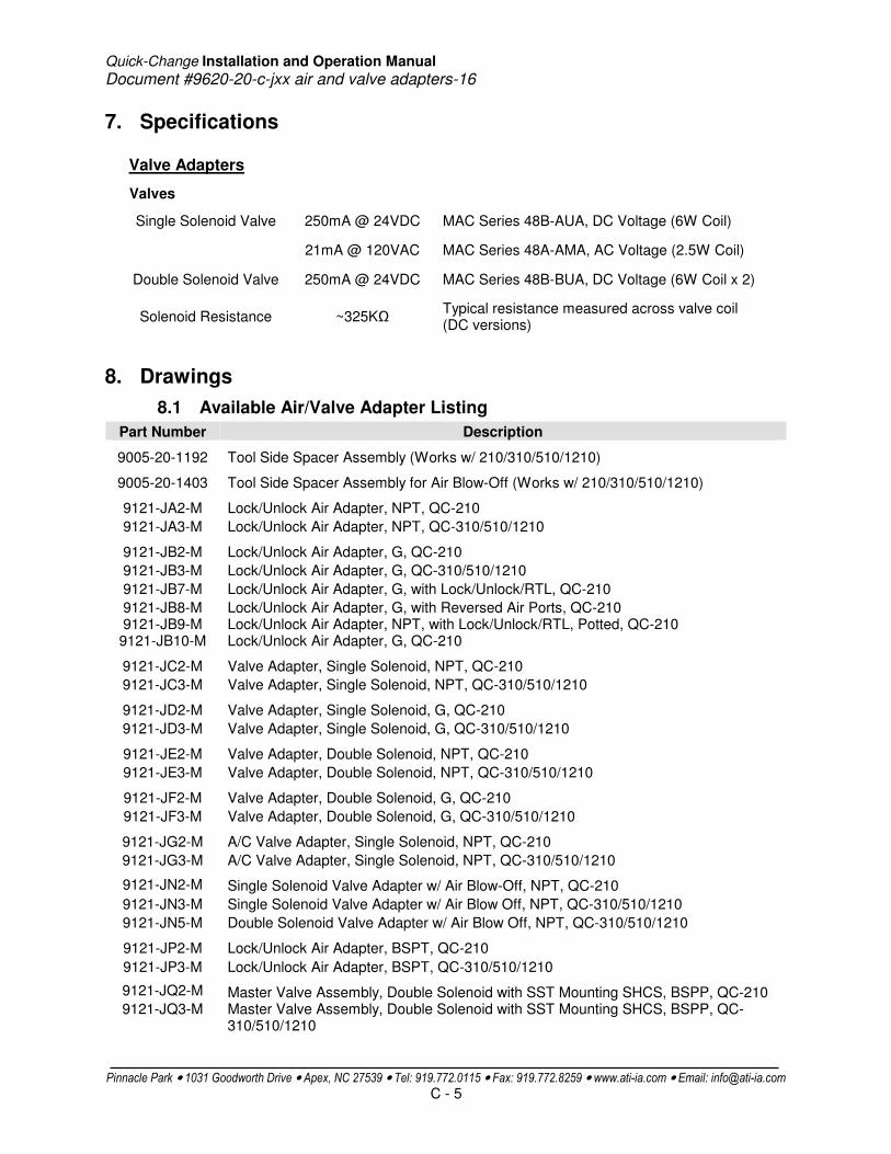
Quick-Change Installation and Operation Manual
Document #9620-20-c-jxx air and valve adapters-16
Pinnacle Park • 1031 Goodworth Drive • Apex, NC 27539 • Tel: 919.772.0115 • Fax: 919.772.8259 • www.ati-ia.com • Email: [email protected]
C - 5
7. Specifications
Valve Adapters
Valves
Single Solenoid Valve 250mA @ 24VDC MAC Series 48B-AUA, DC Voltage (6W Coil)
21mA @ 120VAC MAC Series 48A-AMA, AC Voltage (2.5W Coil)
Double Solenoid Valve 250mA @ 24VDC MAC Series 48B-BUA, DC Voltage (6W Coil x 2)
Solenoid Resistance ~325KΩ Typical resistance measured across valve coil (DC versions)
8. Drawings
8.1 Available Air/Valve Adapter Listing
Part Number Description
9005-20-1192 Tool Side Spacer Assembly (Works w/ 210/310/510/1210)
9005-20-1403 Tool Side Spacer Assembly for Air Blow-Off (Works w/ 210/310/510/1210)
9121-JA2-M Lock/Unlock Air Adapter, NPT, QC-210
9121-JA3-M Lock/Unlock Air Adapter, NPT, QC-310/510/1210
9121-JB2-M Lock/Unlock Air Adapter, G, QC-210
9121-JB3-M Lock/Unlock Air Adapter, G, QC-310/510/1210
9121-JB7-M Lock/Unlock Air Adapter, G, with Lock/Unlock/RTL, QC-210
9121-JB8-M Lock/Unlock Air Adapter, G, with Reversed Air Ports, QC-210 9121-JB9-M Lock/Unlock Air Adapter, NPT, with Lock/Unlock/RTL, Potted, QC-210 9121-JB10-M Lock/Unlock Air Adapter, G, QC-210
9121-JC2-M Valve Adapter, Single Solenoid, NPT, QC-210
9121-JC3-M Valve Adapter, Single Solenoid, NPT, QC-310/510/1210
9121-JD2-M Valve Adapter, Single Solenoid, G, QC-210
9121-JD3-M Valve Adapter, Single Solenoid, G, QC-310/510/1210
9121-JE2-M Valve Adapter, Double Solenoid, NPT, QC-210
9121-JE3-M Valve Adapter, Double Solenoid, NPT, QC-310/510/1210
9121-JF2-M Valve Adapter, Double Solenoid, G, QC-210
9121-JF3-M Valve Adapter, Double Solenoid, G, QC-310/510/1210
9121-JG2-M A/C Valve Adapter, Single Solenoid, NPT, QC-210
9121-JG3-M A/C Valve Adapter, Single Solenoid, NPT, QC-310/510/1210
9121-JN2-M Single Solenoid Valve Adapter w/ Air Blow-Off, NPT, QC-210
9121-JN3-M Single Solenoid Valve Adapter w/ Air Blow Off, NPT, QC-310/510/1210
9121-JN5-M Double Solenoid Valve Adapter w/ Air Blow Off, NPT, QC-310/510/1210
9121-JP2-M Lock/Unlock Air Adapter, BSPT, QC-210
9121-JP3-M Lock/Unlock Air Adapter, BSPT, QC-310/510/1210
9121-JQ2-M Master Valve Assembly, Double Solenoid with SST Mounting SHCS, BSPP, QC-210 9121-JQ3-M Master Valve Assembly, Double Solenoid with SST Mounting SHCS, BSPP, QC-
310/510/1210
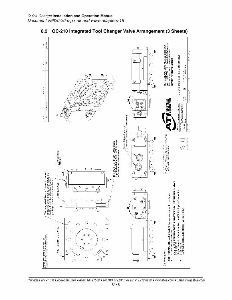
Quick-Change Installation and Operation Manual
Document #9620-20-c-jxx air and valve adapters-16
Pinnacle Park • 1031 Goodworth Drive • Apex, NC 27539 • Tel: 919.772.0115 • Fax: 919.772.8259 • www.ati-ia.com • Email: [email protected]
C - 6
8.2 QC-210 Integrated Tool Changer Valve Arrangement (3 Sheets)
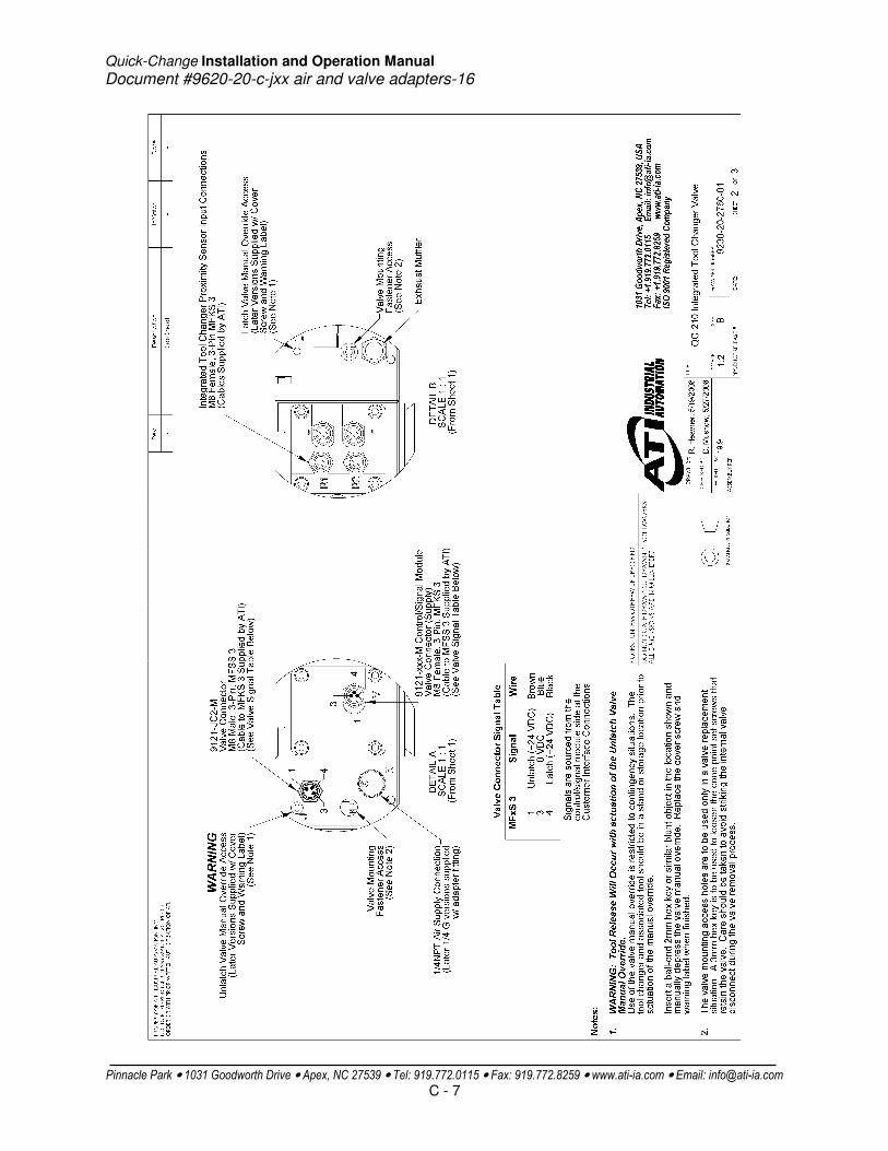
Quick-Change Installation and Operation Manual
Document #9620-20-c-jxx air and valve adapters-16
Pinnacle Park • 1031 Goodworth Drive • Apex, NC 27539 • Tel: 919.772.0115 • Fax: 919.772.8259 • www.ati-ia.com • Email: [email protected]
C - 7

Quick-Change Installation and Operation Manual
Document #9620-20-c-jxx air and valve adapters-16
Pinnacle Park • 1031 Goodworth Drive • Apex, NC 27539 • Tel: 919.772.0115 • Fax: 919.772.8259 • www.ati-ia.com • Email: [email protected]
C - 8
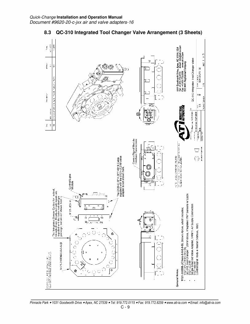
Quick-Change Installation and Operation Manual
Document #9620-20-c-jxx air and valve adapters-16
Pinnacle Park • 1031 Goodworth Drive • Apex, NC 27539 • Tel: 919.772.0115 • Fax: 919.772.8259 • www.ati-ia.com • Email: [email protected]
C - 9
8.3 QC-310 Integrated Tool Changer Valve Arrangement (3 Sheets)

Quick-Change Installation and Operation Manual
Document #9620-20-c-jxx air and valve adapters-16
Pinnacle Park • 1031 Goodworth Drive • Apex, NC 27539 • Tel: 919.772.0115 • Fax: 919.772.8259 • www.ati-ia.com • Email: [email protected]
C - 10
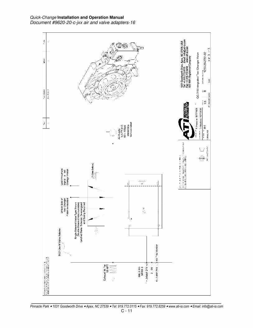
Quick-Change Installation and Operation Manual
Document #9620-20-c-jxx air and valve adapters-16
Pinnacle Park • 1031 Goodworth Drive • Apex, NC 27539 • Tel: 919.772.0115 • Fax: 919.772.8259 • www.ati-ia.com • Email: [email protected]
C - 11

Quick-Change Installation and Operation Manual Document #9620-20-d-aa2,am2-11
Pinnacle Park•1031 Goodworth Drive•Apex, NC 27539•Tel: 919-772-0115•Fax: 919-772-8259•www.ati-ia.com•Email:[email protected]
D - 1
Table of Contents
D. Air Modules ..................................................................................................................2
AA2/AM2 ............................................................................................................................2
1. Product Overview .................................................................................................2
2. Installation ............................................................................................................3
2.1 Installation .................................................................................................3
2.2 Removal ....................................................................................................3
3. Operation .............................................................................................................3
4. Maintenance ........................................................................................................4
4.1 Master-Side Self-Sealing Valve .................................................................4
4.2 Tool-Side Self-Sealing Valve .....................................................................4
5. Troubleshooting ...................................................................................................5
6. Recommended Spare Parts .................................................................................5
7. Specifications .......................................................................................................5
8. Drawings ..............................................................................................................6
8.1 AA2 Air Module Drawing ...........................................................................6
8.2 AM2 Air Module Drawing ...........................................................................7

Quick-Change Installation and Operation Manual Document #9620-20-d-aa2,am2-11
Pinnacle Park•1031 Goodworth Drive•Apex, NC 27539•Tel: 919-772-0115•Fax: 919-772-8259•www.ati-ia.com•Email:[email protected]
D - 2
D. Air Modules
AA2/AM2
1. Product Overview There are several air modules available for the use with the tool changer as described in the table below. The AA2 modules are shown in Figure 1.1.
AA2-M/AA2-T (2) ½ NPT, self-sealing ports master and tool
AA2-M/AA3-T (2) ½ NPT, self-sealing ports on the master/ (2) ½ NPT, unchecked ports on the tool
AM2-M/AM2-T (2) ½ G, self-sealing ports master and tool
AM2-M/AM3-T (2) ½ G, self-sealing ports on the master/ (2) ½ G, unchecked ports on the tool
Table 1.1—Air Modules
NOTE: Self-sealing ports are not to be used for vacuum service.
Figure 1.1—AA2 Air Module (Typical)

Quick-Change Installation and Operation Manual Document #9620-20-d-aa2,am2-11
Pinnacle Park•1031 Goodworth Drive•Apex, NC 27539•Tel: 919-772-0115•Fax: 919-772-8259•www.ati-ia.com•Email:[email protected]
D - 3
2. Installation
The air modules are typically installed by ATI prior to shipment. The steps below outline the field installation or removal as required.
2.1 Installation 1. It may be necessary to clean the mounting surface on the tool changer prior to installing the module
in order to remove any debris that may be present. 2. Align the module to the holes in the tool changer mounting surface using the dowels that are
pressed into the module housing. Push the module up flush with the mounting surface. Apply Loctite-242 (or similar) thread locker to the socket head cap screws and tighten to 89 in-lbs. using a hex key.
3. Connect customer plumbing to the module.
2.2 Removal 1. All customer plumbing connections to the module need to be purged and disconnected. Once the
supply lines have been turned off, the self-sealing valves on the module can be manually actuated to purge the line pressure. Cover the valves with a rag prior to purging in order to keep the air from impinging upon any person.
2. Remove the socket head cap screws and pull the module off the tool changer.
3. Operation The air modules are designed to pass air utilities from the Master to the Tool for use by the customer’s tooling.
Self-sealing valves are provided so that the air circuits do not discharge during tool change and also so that the circuits upstream of the tool changer do not have to be closed down prior to tool change.
DANGER: Power and air should always be removed prior to maintenance or repair.
CAUTION: Air supply should be clean, dry, and non-lubricated. Supply pressure should not exceed 100 psi and should be filtered 50 micron or better. Connection lines should be properly strain-relieved.
!
Quick-Change Installation and Operation Manual Document #9620-20-d-aa2,am2-11
Pinnacle Park•1031 Goodworth Drive•Apex, NC 27539•Tel: 919-772-0115•Fax: 919-772-8259•www.ati-ia.com•Email:[email protected]
D - 4
4. Maintenance Once installed the operation of the air modules is generally trouble free. Periodically the condition of the self-sealing valves should be checked. Replace any damaged or degraded components as necessary. Any contamination in or around the mating surfaces of the modules should be removed with industrial contact cleaner. During inspection, ensure that the fasteners attaching the modules to the tool changer are secure.
The modules may be field serviced as needed. The following list describes how to perform various operations.
4.1 Master-Side Self-Sealing Valve 1. The self-sealing valve assembly (stem, check valve, spring and seals) can be inspected by
removing the stem using a 2.5mm hex key. Be careful not to strip the hex on the stem during removal.
2. Once the stem is removed all seals can be inspected and replaced as required. 3. The spring in the assembly should be inspected and replaced as required. 4. The stem should be inspected for straightness and replaced if bent. 5. To re-install the valve assembly, all components should be arranged in order as they were
removed. (See drawings in Section 8.) 6. Loctite-222 (or similar) thread locker should be applied to the threaded end of the stem and tighten
to 10 in-lbs. and the stem re-installed. The piston will have to be pushed down flush with the mating surface in order to get the stem thread started. It is important that the U-cup seal around the check valve is not damaged during this step. A small, flat-head screwdriver can be used to ensure that the U-cup seal is fully located in the recess and not folded over itself prior to screwing in the stem.
4.2 Tool-Side Self-Sealing Valve 1. The self-sealing valve assembly (plug, spring, piston and seals) can be inspected by removing the
plug on the bottom of the air module using either a spanner wrench or 8mm hex key. It may be necessary to remove the tool side air module to have access to the plug. (Refer to the Section 2 Installation for instructions for module removal.)
2. Once the plug is removed all seals can be inspected and replaced as required. 3. The spring in the assembly should be inspected and replaced as required. 4. The plug may contain a dowel pin. The pin should be inspected for straightness and replaced if
bent. 5. To re-install the valve assembly, all components should be arranged in order as they were
removed. (See drawings in Section 8.) 6. Care should be taken not to damage the O-ring around the plug base during installation. Apply
Magnalube to the o-ring and torque the plug to 20 in-lbs.
DANGER: Power and air should always be removed prior to maintenance or repair.

Quick-Change Installation and Operation Manual Document #9620-20-d-aa2,am2-11
Pinnacle Park•1031 Goodworth Drive•Apex, NC 27539•Tel: 919-772-0115•Fax: 919-772-8259•www.ati-ia.com•Email:[email protected]
D - 5
5. Troubleshooting
Problem Cause Remedy
Air Leakage Damaged/Worn seals
Replace seals.
Debris blocking valve seal
Clean in and around valve components. Ensure air stream is free of large particulates, filter as necessary.
Bent stem Replace stem. Check module attachment to tool changer. Check robot program and ensure parallel approach trajectory during tool changer coupling.
Corrosion Consult ATI for assistance.
Poor Flow Flow path blockage Inspect valve components and supply/return lines for blockage, clean/repair as necessary.
Debris blocking valve seal
Clean in and around valve components. Ensure air stream is free of large particulates, filter as necessary.
Modules Won't Couple
Bent stem, dowel pin
Replace stem, dowels as necessary. Check module attachment to tool changer. Check robot program and ensure parallel approach trajectory during tool changer coupling.
6. Recommended Spare Parts See Drawings in Section 8 of this manual.
7. Specifications
Part Number # Ports Port Size Cv AA2-M/AA2-T 2 ½ NPT 1.6 Maximum pressure of 100psi (6.9bar), Nitrile
seals, Self-sealing on Master and Tool (cannot operate under a vacuum).
AA2-M/AA3-T 2 ½ NPT 1.6 Maximum pressure of 100psi (6.9bar), Nitrile
seals, Self-sealing on Master, unchecked on Tool (cannot operate under a vacuum).
AM2-M/AM2-T 2 ½ G 1.6 Maximum pressure of 100psi (6.9bar), Nitrile seals, Self-sealing on Master and Tool (cannot operate under a vacuum).
AM2-M/AM3-T 2 ½ G 1.6 Maximum pressure of 100psi (6.9bar), Nitrile seals, Self-sealing on Master, unchecked on Tool (cannot operate under a vacuum).

Quick-Change Installation and Operation Manual Document #9620-20-d-aa2,am2-11
Pinnacle Park•1031 Goodworth Drive•Apex, NC 27539•Tel: 919-772-0115•Fax: 919-772-8259•www.ati-ia.com•Email:[email protected]
D - 6
8. Drawings
8.1 AA2 Air Module Drawing

Quick-Change Installation and Operation Manual Document #9620-20-d-aa2,am2-11
Pinnacle Park•1031 Goodworth Drive•Apex, NC 27539•Tel: 919-772-0115•Fax: 919-772-8259•www.ati-ia.com•Email:[email protected]
D - 7
8.2 AM2 Air Module Drawing

Quick-Change Installation and Operation Manual Document #9620-20-E-NA-03
Pinnacle Park • 1031 Goodworth Drive • Apex, NC 27539 • Tel: 919.772.0115 • Fax: 919.772.8259 • www.ati-ia.com • Email: [email protected]
E - 1
Electrical Modules are not used in this application. For a list of available options please refer to our catalog or contact our Sales department. We will be glad to assist you. How to Reach Us
Sales, Service and Information about ATI products: ATI Industrial Automation 1031 Goodworth Drive Apex, NC 27539 USA www.ati-ia.com Tel: 919.772.0115 Fax: 919.772.8259 E-mail: [email protected] Technical support and questions: Application Engineering Tel: 919.772.0115 Fax: 919.772.8259 E-mail: [email protected]

Quick-Change Installation and Operation Manual Document #9620-20-F-NA-02
ATI Industrial Automation, 1031 Goodworth Drive, Apex, NC 27539 (919)-772-0115 www.ati-ia.com
F - 1
High-Power Modules are not used in this application. For a list of available options please refer to our catalog or contact our Sales department. We will be glad to assist you. How to Reach Us
Sales, Service and Information about ATI products: ATI Industrial Automation 1031 Goodworth Drive Apex, NC 27539 USA www.ati-ia.com Tel: 919.772.0115 Fax: 919.772.8259 E-mail: [email protected] Technical support and questions: Application Engineering Tel: 919.772.0115 Fax: 919.772.8259 E-mail: [email protected]

Quick-Change Installation and Operation Manual Document #9620-20-G-IP Shown in Customer Drawing-02
Pinnacle Park • 1031 Goodworth Drive • Apex, NC 27539 • Tel: 919.772.0115 • Fax: 919.772.8259 • www.ati-ia.com • Email: [email protected]
G - 1
If Interface Plates are used in this application, details will be shown in the customer drawing found at the front of this binder. For a list of available options please refer to our catalog or contact our Sales department. We will be glad to assist you. How to Reach Us
Sales, Service and Information about ATI products: ATI Industrial Automation 1031 Goodworth Drive Apex, NC 27539 USA www.ati-ia.com Tel: 919.772.0115 Fax: 919.772.8259 E-mail: [email protected] Technical support and questions: Application Engineering Tel: 919.772.0115 Fax: 919.772.8259 E-mail: [email protected]

Quick-Change Installation and Operation Manual Document #9620-20-H-NA-03
Pinnacle Park • 1031 Goodworth Drive • Apex, NC 27539 • Tel: 919.772.0115 • Fax: 919.772.8259 • www.ati-ia.com • Email: [email protected]
H - 1
Other Modules are not used in this application. For a list of available options please refer to our catalog or contact our Sales department. We will be glad to assist you. How to Reach Us
Sales, Service and Information about ATI products: ATI Industrial Automation 1031 Goodworth Drive Apex, NC 27539 USA www.ati-ia.com Tel: 919.772.0115 Fax: 919.772.8259 E-mail: [email protected] Technical support and questions: Application Engineering Tel: 919.772.0115 Fax: 919.772.8259 E-mail: [email protected]