ati user manual master - voltech.com ati user manual v8.pdfthe ati is one of a family of automatic...
TRANSCRIPT

VOLTECH ATI USER MANUAL PAGE I
ATATATATiiii USER MANUAL
Voltech Instruments Inc. 11637 Kelly Road
Suite 306 Fort Myers FL 33908, U.S.A.
Tel: 239 437 0494 Fax: 239 437 3841 [email protected]
Voltech Instruments Ltd. 148 6th Street
Harwell International Business Centre Didcot, Oxon OX11 ORA, U.K.
Tel: +44 (0) 1235 834555 Fax: +44 (0) 1235 835016
w w w . v o l t e c h . c o m

PAGE II VOLTECH ATI USER MANUAL
Voltech Instruments is committed to a policy of continuous product development. Hence, product specification and the information given in this manual are subject to change without notice.
No part of this publication may be reproduced, stored in a retrieval system, or transmitted in any form, or by any means, electronic, mechanical photocopying, recording or otherwise, without prior written permission of Voltech Instruments.
Voltech Instruments 2002-2005. All rights reserved.
The Voltech ATi is protected by the following patents:
USA: US 5500598
UK: 2261957B
Europe: 0621953B
Microsoft, Windows and the Windows logo are either registered trademarks or trademarks of Microsoft Corporation in the United States and/or other countries.
Voltech Part Number: 98-067, Issue 8, October 2005.

VOLTECH ATI USER MANUAL PAGE III
DANGER OF ELECTRIC SHOCK
Only qualified personnel should install this equipment, after reading and understanding this user manual. If in doubt, consult your supplier.
RISQUE D'ELECTROCUTION
L'installation de cet équipement ne doit être confiée qu'à un personnel qualifié ayant lu et compris le présent manuel d'utilisation. Dans le doute, s'adresser au fournisseur.
GEFAHR VON ELEKTRISCHEM SCHOCK Nur entsprechend ausgebildetes Personal ist berechtigt, diese Ausrüstung nach dem Lesen und Verständnis dieses Anwendungshandbuches zu installieren. Falls Sie Zweifel haben sollten, wenden Sie sich bitte an Ihren Lieferanten.
RISCHIO DI SCARICHE ELETTRICHE
Solo personale qualificato può installare questo strumento, dopo la lettura e la comprensione di questo manuale. Se esistono dubbi consultate il vostro rivenditore.
! !
! !
! !
! !

PAGE IV VOLTECH ATI USER MANUAL
Contents
1 INTRODUCTION ............................................................................................ 1-1 1.1 How to Use this Manual .................................................................................. 1-5 1.2 General Safety Instructions............................................................................. 1-6 1.3 ATi and AT3600 .............................................................................................. 1-7 1.4 Tests Supplied ................................................................................................ 1-8 1.5 ATi Features Summary ................................................................................. 1-11 1.6 Typical Production Installation....................................................................... 1-12 1.7 Using the ATi for Design and Evaluation....................................................... 1-14 1.8 Overview ....................................................................................................... 1-15 1.9 How Does the ATi Tester Run a Test?.......................................................... 1-26
2 Getting Started......................................................................................... 2-1 2.1 Introduction ..................................................................................................... 2-5 2.2 Installation..................................................................................................... 2-10 2.3 Quick Start Tutorial ....................................................................................... 2-19 2.4 Self-Test........................................................................................................ 2-49 2.5 Production Mode........................................................................................... 2-52 2.6 Stop on Fail ................................................................................................... 2-69 2.7 Trim............................................................................................................... 2-71 2.8 Fixture Compensation ................................................................................... 2-73 2.9 Set-up Mode ................................................................................................. 2-77
3 PROGRAM EDITOR ....................................................................................... 3-1 3.1 Creating a Program......................................................................................... 3-5 3.2 Creating the Transformer Schematic .............................................................. 3-6 3.3 Creating the Test Program............................................................................ 3-13 3.4 Using the Measure Button............................................................................. 3-31 3.5 Error Codes................................................................................................... 3-42

VOLTECH ATI USER MANUAL PAGE V
3.6 Fixture Compensation (see also section 2.8)......................................... 3-46 3.7 Programming Hints and Tips......................................................................... 3-48
4 AT SERIES SERVER .....................................................................................4-1 4.1 Introduction ..................................................................................................... 4-5 4.2 Test Program Handling ................................................................................... 4-6 4.3 Test Results Handling ................................................................................... 4-11 4.4 License Registration...................................................................................... 4-50
5 FIXTURES ....................................................................................................5-1 5.1 Introduction ..................................................................................................... 5-5 5.2 Description ...................................................................................................... 5-6 5.3 Fixture System Specification ......................................................................... 5-12 5.4 Fixture Parts Available from Voltech ............................................................. 5-13 5.5 Kelvin Connections........................................................................................ 5-18
6 FRONT-PANEL MODES .................................................................................6-1 6.1 LCR Mode Basic Functions............................................................................. 6-5 6.2 Tests Available in the LCR Modes ................................................................ 6-17 6.3 LCR Menus ................................................................................................... 6-19 6.4 Compensation ............................................................................................... 6-29 6.5 LCR Mode Error Messages........................................................................... 6-35 6.6 Program Mode .............................................................................................. 6-39
7 TESTS AND TEST CONDITIONS ......................................................................7-1 7.1 Introduction ..................................................................................................... 7-4 7.2 Series and Parallel Circuits ......................................................................... 7-123 7.3 Capacitor Measurements ............................................................................ 7-125
8 SPECIFICATIONS ..........................................................................................8-1 8.1 Specifications Summary – Available Tests...................................................... 8-5 8.2 Accuracy Specifications – Available Tests ...................................................... 8-8 8.3 Interface Details ............................................................................................ 8-25 8.4 EMC Compliance .......................................................................................... 8-35
9 WARRANTY AND SERVICE.............................................................................9-1

PAGE VI VOLTECH ATI USER MANUAL
9.1 Warranty ......................................................................................................... 9-5 9.2 Limitation of Warranty ..................................................................................... 9-5 9.3 Service and Calibration ................................................................................... 9-6 9.4 Obtaining Service and Applications Support ................................................... 9-6 9.5 Firmware Upgrades......................................................................................... 9-7
10 INDEX.................................................................................................... 10-1

VOLTECH ATI USER MANUAL PAGE 1-1
1 INTRODUCTION
Thank you for choosing to use this Voltech product. If you experience
any difficulty during installation or use of the ATi or are unsure of any of
its features or abilities, please do not hesitate to contact either your local
supplier or a Voltech main service centre as listed inside the front cover.

INTRODUCTION
PAGE 1-2 VOLTECH ATI USER MANUAL

INTRODUCTION
VOLTECH ATI USER MANUAL PAGE 1-3
Contents - Introduction
1.1. HOW TO USE THIS MANUAL ......................................................................1-5 1.2. GENERAL SAFETY INSTRUCTIONS.............................................................1-6 1.3. ATI AND AT3600.....................................................................................1-7 1.4. TESTS SUPPLIED .....................................................................................1-8
1.4.1. Standard Program Tests.......................................................................... 1-8 1.4.2. Optional Program Tests........................................................................... 1-8 1.4.3. ATi LCR Mode Functions......................................................................... 1-9
1.5. ATI FEATURES SUMMARY ......................................................................1-11 1.6. TYPICAL PRODUCTION INSTALLATION .....................................................1-12 1.7. USING THE ATI FOR DESIGN AND EVALUATION........................................1-14 1.8. OVERVIEW.............................................................................................1-15
1.8.1. Creating Programs - The Editor ............................................................. 1-16 1.8.2. Storing Programs and Results - The Server .......................................... 1-17 1.8.3. Transferring Programs between Editor and Server................................ 1-18 1.8.4. Executing Programs .............................................................................. 1-20 1.8.5. Test Fixtures.......................................................................................... 1-23 1.8.6. Operating the AT Series Testers in Production Test.............................. 1-24
1.9. HOW DOES THE ATI TESTER RUN A TEST?.............................................1-26

INTRODUCTION
PAGE 1-4 VOLTECH ATI USER MANUAL

INTRODUCTION
VOLTECH ATI USER MANUAL PAGE 1-5
1.1 HOW TO USE THIS MANUAL
Welcome to the Voltech ATi. Please study this introductory chapter of the manual carefully. It will help you to set-up your tester quickly and safely.
The following symbol conventions are used throughout:
Important safety information. To ensure operator safety, all safety information must be read and understood.
Important information that explains a general principle or refers to other sections of the manual.
The contents of this manual are believed to be accurate at the time of printing. Voltech reserves the right, however, to change the operation or specification of the ATi without notice. No liability is accepted for the inappropriate, negligent, or incorrect set-up of the ATi by the user, by either manual or automated means.
i
!

INTRODUCTION
PAGE 1-6 VOLTECH ATI USER MANUAL
1.2 GENERAL SAFETY INSTRUCTIONS
WARNING: The ATi must be connected to a safety ground (earth). Only insert the power lead into a socket with a protective ground contact.
Ensure that the power lead is in good condition and free from damage before use.
Replace the fuse only with the same type and rating as indicated on the rear of the ATi.
Refer servicing only to qualified personnel who understand the danger of shock hazards.
WARNING: The ATi wound component tester can generate voltages of up to 500V during insulation resistance testing. Although the available energy of the source has been limited in accordance with EN61010-1 and can be considered ‘safe’, care should be taken to avoid accidental or unexpected electrical shocks.
• Ensure operators are aware of the potential shock hazard.
• Ensure operators are trained to avoid making contact with the part being tested or any exposed parts of the fixture during an IR test.
• Construct safe fixtures using the guidelines given in the fixturing section of this manual.
• Beware of testing parts with high turns ratios such that a small applied test signal can generate an unsafe high voltage.
• Beware of energy stored with the capacitance or inductance of the part being tested when handling the part after test.
!
!

INTRODUCTION
VOLTECH ATI USER MANUAL PAGE 1-7
1.3 ATI AND AT3600
The ATi is one of a family of automatic testers from Voltech that share the same fixture construction and PC Editor and Server software. ATis and AT3600s can share the same Server application, simultaneously recalling test programs and recording test results.
Features: ATi AT36020 way switching matrix ! ! PC test editor and results server ! ! Test fixture system ! ! Small signal tests ( e.g. inductance, capacitance, turns ! ! Telecom tests (e.g. return loss, longitudinal balance) ! ! Insulation resistance 500V 7000V Hi-pot AC 5500V Hi-pot DC 7000V Surge testing 5000V Magnetizing current and open circuit voltage 270V Watts/Stress Watts ! Leakage current !
ATATATAT3600 ATiiii

INTRODUCTION
PAGE 1-8 VOLTECH ATI USER MANUAL
1.4 TESTS SUPPLIED
At the time of printing, the following tests are available for the ATi:
1.4.1 Standard Program Tests CTY Continuity R DC resistance RLS AC resistance series circuit RLP AC resistance parallel circuit LS Inductance series circuit LP Inductance parallel circuit LSB Inductance series circuit with bias LPB Inductance parallel circuit with bias C Interwinding capacitance QL Quality factor D Dissipation factor (tanδ) Z Magnitude of complex impedance ZB Complex impedance with bias ANGL Angle of complex impedance TR Turns ratio and phase (+ or -) by voltage IR Insulation resistance
1.4.2 Optional Program Tests
LL Leakage inductance LLO Leakage inductance with user offset R2 DC resistance match L2 Inductance match C2 Capacitance match TRL Turns ratio by inductance PHAS Interwinding phase GBAL General longitudinal balance LBAL Longitudinal balance

INTRODUCTION
VOLTECH ATI USER MANUAL PAGE 1-9
Optional program tests continued…
ILOS Insertion loss RLOS Return loss LVOC Low voltage open circuit RESP Frequency response TRIM Trim adjustable part OUT User port relay control LSBX Inductance series circuit with external bias LPBX Inductance parallel circuit with external bias
1.4.3 ATi LCR Mode Functions
Measurement Symbol Units Display Units
DC resistance Rdc Ohms Ω
DC resistance using high voltage source IR Ohms Ω
AC resistance series circuit R Ohms Ω
AC resistance parallel circuit R Ohms Ω
Inductance series circuit L Henries H
Inductance parallel circuit L Henries H
Capacitance series circuit CS Farads F
Capacitance parallel circuit CP Farads F
Quality Factor Q
Dissipation Factor or tanδ D
AC impedance magnitude of complex impedance Z Ohms Ω
Phase angle of impedance θ Degrees °
AC reactance imaginary part of impedance X Ohms Ω
Turns ratio by voltage TR
Turns ratio by inductance TRL
Leakage inductance LL Henries H
Interwinding capacitance C Farads F

INTRODUCTION
PAGE 1-10 VOLTECH ATI USER MANUAL
To determine which options were installed on your tester during manufacture, check the list attached to the calibration certificate shipped with your ATi. i

INTRODUCTION
VOLTECH ATI USER MANUAL PAGE 1-11
1.5 ATI FEATURES SUMMARY
The ATi tester is a fast, accurate and versatile automatic LCR meter.
FAST Typically more than 10 DIFFERENT tests per second.
• 20 way switch matrix.
• Automatically switches from making measurements on one winding of a transformer to another winding.
• Measures across different windings.
• No need to manually change connections.
• Fast execution of a sequence of different tests on multiple windings of a transformer.
ACCURATE – 0.05% basic
VERSATILE
• Easy to use.
• High-speed production tester.
• Laboratory grade LCR meter.
• Upgrades and new tests installed from disk.
• Inductance from 1nH to 1MH
• Any frequency from 20Hz to 3MHz
• Any voltage from 1mV to 5V
• AC constant current source 20µµµµA to 100mA
• DC bias up to 1A

INTRODUCTION
PAGE 1-12 VOLTECH ATI USER MANUAL
The ATi is very easy to use. However, it is a complex instrument, which can be installed and operated in many ways.
In order to maximize the benefits that the ATi can bring to your test environment, please study the following section carefully.
1.6 TYPICAL PRODUCTION INSTALLATION
Manual or robotic operation
• Barcode input
• Run-pad or footswitch to initiate operation
• Simple PASS/FAIL operation by an unskilled operator
Results
• Direct printing from the ATi printer port
• Results archiving to disk using the Server application
• Results for analysis can be easily exported to other Windows applications
Editor PC - used only when creating or editing test programs.
Server PC - for handling detailed results and large numbers of test
programs.
Untestedtransformers
PASS FTested transfo
Tested transformers
Pass Fail

INTRODUCTION
VOLTECH ATI USER MANUAL PAGE 1-13
Test Program Creation
• Simple, easy to use, Windows based Editor for creating test programs. (Chapter 3).
• Requires no software programming skills or expertise.
• Test conditions may be entered manually, or chosen automatically by measuring a sample transformer.
Program Archive ~ Management
• Windows based Server software for easy management of all test programs. (See chapter 4.)
• Optionally, programs may be resident in the tester for stand-alone operation.

INTRODUCTION
PAGE 1-14 VOLTECH ATI USER MANUAL
1.7 USING THE ATI FOR DESIGN AND EVALUATION • Tests: L, C, Z, D, Q, Rac, X, Z, θ, Rdc, Insulation Resistance, Turns Ratio,
Leakage Inductance. Bias current up to 1A.
• Fully programmable (5V, 3MHz) or AUTOMATIC test conditions.
• 0.05% basic accuracy.
• 4-terminal (Kelvin) connections using high quality leads supplied.
• Easy to use.
• Compensation for stray resistance, inductance and capacitance.

INTRODUCTION
VOLTECH ATI USER MANUAL PAGE 1-15
1.8 OVERVIEW
This section gives a more detailed overview of your ATi and how to use it. It is recommended that you read this section before attempting to use your tester.
Topics covered in this overview:
• The features and functionality of the ATi in a production environment.
• What appears in a test program.
• How programs are created, archived and then used in actual test.
• Test fixtures.
• Typical manual and robotic test situations.
• Internal functionality How the tester executes each test.
Note:
This overview is intended as an introduction to each of the above topics, so that you may quickly understand what may be possible. If further details are required on any topic, they can be found in later chapters of this manual.

INTRODUCTION
PAGE 1-16 VOLTECH ATI USER MANUAL
1.8.1 Creating Programs - The Editor The test program is, simply, the list of tests that you wish to apply to your transformer.
Individual transformers will each have their own program, but as an example, a typical program for a three winding switch-mode power supply transformer could be as follows:
The Test Program Editor, supplied with your tester, allows you to create such a program, without software programming skills. Each test required for the program is selected from a list of available tests by clicking with the mouse. The test details (such as the transformer terminals, test conditions, and pass / fail limits) are then entered into a form fill dialogue box.
Part Number: SMPSE42-A
W1
W2
W3
Program:
ResistanceResistanceResistanceInductanceTurns RatioTurns RatioInsulation Resistance
W1W2W3W1W1 to W2W2 to W3W1 to W2 + W3

INTRODUCTION
VOLTECH ATI USER MANUAL PAGE 1-17
Normally, the Editor is used with the auxiliary port of the tester connected to a spare COM-port on the PC:
Pull-down menus in the Editor allow you to download the program to the tester, so that it may be run for the purposes of evaluation and modification.
1.8.2 Storing Programs and Results - The Server The Editor software previously described allows you to create and evaluate each individual test program. It is not intended to manage the large numbers of test programs that may be required on a daily basis once they are in production use. This is the function of a second PC program supplied with your ATi called the Server.
Usually, the Server would be installed on a PC with access to a large disk that could be attached to the PC itself, or connected via a network. The Server (and disk) would then be used for any of the following purposes:
• To provide the master archive for test programs
• To archive test results.
• To interface to an SPC package.
• To remotely control the tester.
The tester has a separate 'server' port on its rear panel for connecting to the PC.
Auxiliary port PC running the Editor software

INTRODUCTION
PAGE 1-18 VOLTECH ATI USER MANUAL
1.8.3 Transferring Programs between Editor and Server Within your test environment there are several possible ways in which the Server and Editor may be installed and used, depending on how many separate PCs are available.
The standard installation uses separate PCs for the Editor and Server:
Transferring a new test program from the Editor to the Server archive can be done in any of three ways:
• Via the tester
• Directly from PC to PC via a floppy disk
• Via a network connection between the PCs using Save As in the editor to transfer the program to the directory used by the Server for programs.
Programs
Auxiliary port Server port

INTRODUCTION
VOLTECH ATI USER MANUAL PAGE 1-19
With both Server and Editor installed on the same PC, transferring a new test
program from the Editor to the Server archive can be done in either of two ways:
• Via the tester (if the auxiliary port connection is made).
• Directly from the Editor using save as to the directory used by the Server for programs.
Auxiliary port(connected using
the Editor)
Server port

INTRODUCTION
PAGE 1-20 VOLTECH ATI USER MANUAL
Server
Programs/ Results
Programs/ Results
Programs/ Results
1.8.4 Executing Programs Large Production Facility
The standard installation in a large production facility could use several testers, together with a Server PC for test program and results archive:
Advantages
• Convenient storage and management of large numbers of test programs (e.g. >1000).
• Easy storage and management of test results.
• Importing results into other Windows applications for analysis.
• The Server PC can be located away from the test area, for example in a supervisors office, allowing results analysis to be performed where it is required.
• Up to eight AT series testers may be connected to each Server PC.
Server PC

INTRODUCTION
VOLTECH ATI USER MANUAL PAGE 1-21
Limitations
• Requires the Server PC to be permanently connected. This is to allow the tester uninterrupted access to the Server, for the purposes of accessing programs and storing results.
• Usually requires an additional PC (which could be a portable) to be attached locally to (the auxiliary port of) one of the testers when a new program needs to be developed and evaluated.

INTRODUCTION
PAGE 1-22 VOLTECH ATI USER MANUAL
Small Production Facility
At the other extreme and possibly more suitable for a small production facility with a single AT series tester and limited or temporary access to a PC:
1. Connect the AT to the PC (running both Editor and Server software) as shown above when developing the test programs.
2. Download a group of programs from the Server to the AT, where they will be held in the internal non-volatile memory.
3. Remove the PC, and run all the production test programs from the AT internal memory.
Advantages
• Requires only occasional use of a PC (which could be a portable) to develop test programs and load them into the AT.
• Test programs can be executed by the AT without the PC attached, which may be of advantage if the working space is limited.
Limitations
• Suitable for small numbers of test programs (e.g. <50).
• Test results cannot be archived to disk, or analysed by other Windows based applications.

INTRODUCTION
VOLTECH ATI USER MANUAL PAGE 1-23
1.8.5 Test Fixtures When running the test program in production, how do you connect your transformer with its own arrangement of terminals to the test nodes of the AT Series Tester?
The AT Series of transformer testers has been designed with its own test fixture system to answer just this question:
• Fixtures are constructed on a standard fixture board which fits into the top surface of the tester.
• The fixture system uses Kelvin connections to give the best possible measurements when testing wound components.
• The fixture system will accommodate different types of connectors suitable for both PCB mounting and flying lead transformers.
• A single test fixture can be used for all transformers wound on the same bobbin.
Please see the fixtures section (chapter 5) of this manual for more information.

INTRODUCTION
PAGE 1-24 VOLTECH ATI USER MANUAL
1.8.6 Operating the AT Series Testers in Production Test The ATi is suitable for use in both manual and robotic production situations. Manual Use – Testing Smaller Batches of Different Transformers:
Operator:
1. Chooses transformer part number from a list or swipes a barcode
2. Fits the fixture as prompted
3. Touches pad or presses footswitch
Run/Stop/Fail/Busy signals for process
control
Failed parts for rejection or rework
Remote PC records all test data for statistical analysis using
Voltech server software
Parts to be tested before finishing
Good parts for further processes
Low cost fixture plates
• Quick connections to the transformer under test
• Rapid change of fixture for different transformer types
Touch pads or foot switch to start the test

INTRODUCTION
VOLTECH ATI USER MANUAL PAGE 1-25
Robotic /Automatic Handling Use
In robotic situations, the tester's remote port provides the digital inputs and outputs for connecting into your system:
Again the tester may be connected to a Server PC, or used stand-alone as described above.
Run/Stop/Fail/Busy signals for process
control
Failed parts for rejection or rework
Remote PC records all test data for statistical analysis using
Voltech server software
Parts to be tested before finishing
Good parts for further processes

INTRODUCTION
PAGE 1-26 VOLTECH ATI USER MANUAL
1.9 HOW DOES THE ATI TESTER RUN A TEST?
It is not necessary to understand how the tester works in order to install, program or operate it successfully. This section is provided for your information only.
The ATi consists of the following 7 basic functional blocks:
Relay Switching Matrix
The relay switching matrix is used to connect the selected test source and measurement circuits to the particular nodes required in the test.
Source 1 Up to 5V rms DC and 20Hz to 3MHz
Source 2 Up to 1A constant current
Processors
Relay Matrix
Measurement Circuits
Keyboard, Display and Interfaces
Source 3 Up to 500V dc for IR

INTRODUCTION
VOLTECH ATI USER MANUAL PAGE 1-27
Test Sources
The three sources are fully programmable in thousands of steps of voltage, current and frequency.
Measurement Circuits
Fully auto-ranging, the measurement circuits are capable of measuring from µV and nA to 500V and 4Apk with great precision.
Keyboard, Display and Interfaces
A broad range of programming, results display and storage methods.
Processors
The AT series testers are based on a two-processor design:
1. A standard microprocessor that acts as controller, and also drives the relay matrix, the keyboard and display, and the various interfaces.
2. A fast digital signal processor that controls the test sources and performs the measurements.
The test sources, relay matrix and measurement circuits are all under direct control of the processors to ensure optimum speed, accuracy and reliability.
Running a Test
When the test program is loaded into the tester, each individual test is assembled into a sequence of operations involving the components in the functional block diagram shown previously. The sequence is different for each test, and in some cases, it depends on which are the preceding and following tests in the program; but in all cases, it is optimised to give the best measurement speed and accuracy.

INTRODUCTION
PAGE 1-28 VOLTECH ATI USER MANUAL
As an example, the sequence for measuring inductance may be summarized below:
Y
N
Ramp-downSource Voltage
CalculateInductance
Compare WithTest Limits
Signal LevelCorrect?
Select Nodes(Relay Switching)
Select TypeOf Source
Change SourceVoltage
Set-up SourceFrequency
Ramp-up SourceVoltage
Measure V & IHarmonic Analysis
For other tests, the sequence may be more complicated.
Notes
All the relay switching is completed before the test source is energized. This will ensure that there can be no arcing, and prolong the life of the relays.
In contrast to some LCR bridges, the AT Series testers trim the test source to give the user programmed test conditions. This will guarantee that the same test conditions are applied to all transformers that use the same test program.
At the end of the test, the source is safely ramped down, so that the relay switching for any subsequent test will always occur with the source removed.

VOLTECH ATI USER MANUAL PAGE 2-1
2 Getting Started

GETTING STARTED
PAGE 2-2 VOLTECH ATI USER MANUAL

GETTING STARTED
VOLTECH ATI USER MANUAL PAGE 2-3
Contents – Getting Started
2.1. INTRODUCTION.........................................................................................2-5 2.1.1. Package Contents ....................................................................................... 2-6 2.1.2. The ATi Front Panel .................................................................................... 2-7 2.1.3. Other Data Inputs........................................................................................ 2-9
2.2. INSTALLATION........................................................................................2-10 2.2.1. Switching on the ATi.................................................................................. 2-10 2.2.2. Installing the PC Editor.............................................................................. 2-12 2.2.3. Installing the PC Server............................................................................. 2-14
2.3. QUICK START TUTORIAL ........................................................................2-19 2.3.1. Introduction ............................................................................................... 2-19 2.3.2. Drawing the Transformer Schematic ......................................................... 2-20 2.3.3. Creating the Test Program ........................................................................ 2-22 2.3.4. Running the Program from the Editor........................................................ 2-30 2.3.5. Server Quick Start ..................................................................................... 2-33 2.3.6. Running a Program on the Tester ............................................................. 2-36 2.3.7. Storing Programs ...................................................................................... 2-45
2.4. SELF-TEST ............................................................................................2-49 2.5. PRODUCTION MODE...............................................................................2-52
2.5.1. Production Mode With No Options Enabled .............................................. 2-53 2.5.2. Error Messages......................................................................................... 2-56 2.5.3. Indications Displayed While Tests Are Running........................................ 2-58 2.5.4. Re-measuring Fixture Compensation........................................................ 2-60 2.5.5. Execute Mode With Options Enabled........................................................ 2-61
2.6. STOP ON FAIL........................................................................................2-69 2.7. TRIM......................................................................................................2-71 2.8. FIXTURE COMPENSATION .......................................................................2-73

GETTING STARTED
PAGE 2-4 VOLTECH ATI USER MANUAL
2.9. SET-UP MODE ....................................................................................... 2-77 2.9.1. Set-up Softkey........................................................................................... 2-78 AT Password....................................................................................................... 2-83 Resetting Tester Set-Up Options ........................................................................ 2-83 2.9.2. Groups Softkey ......................................................................................... 2-84

GETTING STARTED
VOLTECH ATI USER MANUAL PAGE 2-5
2.1 INTRODUCTION This chapter is designed to introduce you to the basic facilities of the ATi and help you to realize the benefits of automated transformer testing in the shortest possible time.
If you are reasonably familiar with the testing of transformers and how to install and use Windows programs, this chapter may be all that you need, but you are nevertheless urged to read and understand the complete contents of this manual in order to achieve the maximum benefits that the ATi can bring.
For production testing, the use of good-quality test fixtures is very important. Please see the fixturing section of this manual for details of parts that are available from Voltech.
If you have any questions or are unsure of what to do at any point, please do not hesitate to contact your Voltech supplier.
Once installed:
The ATi will enable you to rapidly, accurately and reliably test wound components in your production or goods inwards environment.
The PC Editor will enable you to quickly and easily create test programs for your tester, without any specialized knowledge of computer programming.
The PC Server will provide a storage system for archiving both the test programs and the test results.
In this chapter, you will learn:
• How to install the tester.
• How to set up the Editor and Server software.
• How to create and run a simple test program.

GETTING STARTED
PAGE 2-6 VOLTECH ATI USER MANUAL
2.1.1 Package Contents The following items are supplied in the packing case along with this manual:
• ATi transformer tester
• Power cord
• A BNC-to-Kelvin clip lead (four color-coded BNCs to two clips)
• An 'LCR' fixture with four Kelvin leads attached
• 9-pin D 9-pin D F-F cable
• 9-pin D 25-pin D F-F cable
• 25-pin D 25-pin D F-F cable
• CD-ROM inside the cover of this manual, which contains the Editor and Server installation files and other important information
• Calibration certificate
• Product registration information
Please report any missing items to your Voltech supplier.
Returning your product registration card will ensure that you continue to receive the latest product and application information.

GETTING STARTED
VOLTECH ATI USER MANUAL PAGE 2-7
2.1.2 The ATi Front Panel
The front panel of the ATi is mounted towards of the rear of the fixture bay to allow easy access for loading transformers and to avoid accidental damage to the display and keys. The main features are as follows:
LCD Display The brightly lit graphics display is used both to display test results, and to provide prompts for data entry within the menu structure.
RUN Indicator The RUN indicator is a yellow LED. This is illuminated when the tester is busy, for example when running a test program.
PASS Indicator The PASS indicator is a green LED. This is illuminated after running a test program, when the result is Pass.
FAIL Indicator The FAIL indicator is a red LED. This is illuminated after running a test program, when the result is Fail.
Numeric
RUN Indicator
PASS Indicator
FAIL Indicator
Softkeys
Liquid Crystal Display (LCD)
BNC connectors

GETTING STARTED
PAGE 2-8 VOLTECH ATI USER MANUAL
Beeper A programmable beeper is built into the ATi to give an audible indication of PASS or FAIL as desired.
Logic level signals representing the RUN, PASS, FAIL and BEEP actions are available on the REMOTE port at the back of the ATi for use with automatic handling equipment and external indicators.
Keypad The keypad allows you to enter text data such as the part number (i.e. test program name) of the transformer to be tested.
Softkeys The six softkeys adjacent to the LCD are provided for functions that vary with different aspects of the testers operation. The function for each softkey at any given time is shown in the text boxes at the right hand side of the LCD.

GETTING STARTED
VOLTECH ATI USER MANUAL PAGE 2-9
2.1.3 Other Data Inputs To give you the greatest ergonomic flexibility, methods other than the keyboard can be used to initiate testing and enter data.
Run-pads
Two stainless steel discs, at the front of each side of the ATi. Lightly touching the programmable run-pads will start the programmed test sequence.
Footswitch
The Run input of the Remote Port on the tester's rear panel can be optionally connected to a footswitch.
Barcode Input
A barcode reader connected to the Barcode Port on the tester's rear panel can optionally be used to input text data, such the name of the test program, or the transformer batch or serial number of the transformer.

GETTING STARTED
PAGE 2-10 VOLTECH ATI USER MANUAL
2.2 INSTALLATION
2.2.1 Switching on the ATi Place the tester on a stable, level work surface in the position where it is to be used.
Ensure that the top surface of the tester is not fitted with any test fixture and nothing is touching any of the test nodes. Connect the tester's line input to the available supply, and switch on using the switch next to the line input at the back of the ATi. 0 = off.
You must connect the power lead to a socket with a safety ground contact.
When the ATi tester is switched on it performs a self-test, which lasts for about 10 seconds. During power-on self-test, you will see on information concerning your ATis configuration on the display, including the firmware version.
When the power-on self-test has finished, you should see the following display:
The tester is now at the top-level menu, and the softkeys allow you to select which of the five main functions you require:
!
GETTING STARTED
VOLTECH ATI USER MANUAL PAGE 2-11
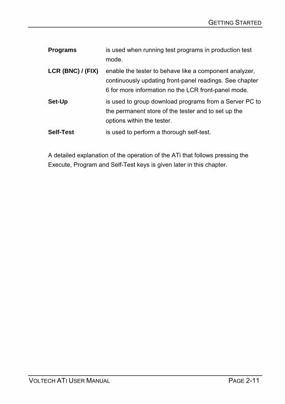
Programs is used when running test programs in production test mode.
LCR (BNC) / (FIX) enable the tester to behave like a component analyzer, continuously updating front-panel readings. See chapter 6 for more information no the LCR front-panel mode.
Set-Up is used to group download programs from a Server PC to the permanent store of the tester and to set up the options within the tester.
Self-Test is used to perform a thorough self-test.
A detailed explanation of the operation of the ATi that follows pressing the Execute, Program and Self-Test keys is given later in this chapter.

GETTING STARTED
PAGE 2-12 VOLTECH ATI USER MANUAL
2.2.2 Installing the PC Editor Connect the tester's auxiliary port to a spare COM port on the PC as shown. The type of connector on the PC will determine the cable that you use. For most PCs this will be a 9-pin female (PC) to 9-pin female (ATi).
Switch on the power supply to the PC
Before attempting to install the Editor, check that your PC satisfies the following hardware requirements:
PC processor 486 or better
Memory 4MB minimum
Hard disk space 2MB minimum
Operating system Windows 95 or newer
Supported screen resolutions 640 x 480, 800 x 600 1024 x 768, 1280 x 1024
CD-ROM drive x2 minimum speed
To install the Editor software, place the ATi CD-ROM supplied with your tester into the CD-ROM drive of the computer and follow the on-screen instructions.
Auxiliary port
COM port

GETTING STARTED
VOLTECH ATI USER MANUAL PAGE 2-13
1. The set-up program will suggest a directory in which to place the Editor files:
C:\Program Files\Voltech Instruments\Voltech AT Editor
This directory will be created if it does not already exist. If you want to place the files elsewhere, browse to another directory.
If you have a previous version of the Editor software already installed on your PC, the procedure outlined above may also be used to install a new version. None of your program files will be lost. The same Editor program is used for all AT Series testers (excluding the discontinued AT3500 and AT1000). PC COM Port Configuration When the installation of the Editor has been completed, you will see the Editor icon in the program group Voltech Software. Double-click with the left mouse button on the Editor icon to start the program.
Initially, configure the Editor to use the chosen COM port:
1. From the top-level Setup menu, select Communications.
2. In the dialogue box shown here, select he PC communications port that is connected to the tester.
WARNING: If the chosen ‘COM’ port is reserved by another Windows application, an error message will appear. You should select another port. i

GETTING STARTED
PAGE 2-14 VOLTECH ATI USER MANUAL
2.2.3 Installing the PC Server Check that your PC satisfies the following hardware requirements:
PC processor 486 or better
Memory 4MB minimum
Hard disk space 3MB minimum
(Note: 3MB does not include disk space required for storing programs or test results)
Operating system Windows 95 or later
CD-ROM drive x2 minimum speed To install the Server software, follow the same basic instructions as for the Editor. The Server is often installed on a different PC to that which will be used for the Editor, depending on your production needs. A Server PC needs to be permanently connected to the ATi only if you wish to store test results or use a central program store rather than the ATis own memory.
Server Hardware Connections
In some applications, you may wish to position the Server PC some distance away from the tester, which will require a cable longer than the one supplied. The AT Series Server port connector details are shown in Chapter 8, to enable you to make up a cable of the length you require.
To use more than one or two AT Series Testers with the same Server host PC, an intelligent COM port expansion card will be required. The server application supports the DIGIBOARD XE eight-channel device.
GETTING STARTED
VOLTECH ATI USER MANUAL PAGE 2-15
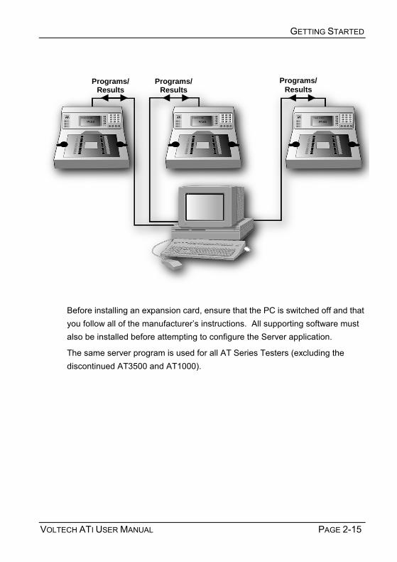
Before installing an expansion card, ensure that the PC is switched off and that you follow all of the manufacturers instructions. All supporting software must also be installed before attempting to configure the Server application.
The same server program is used for all AT Series Testers (excluding the discontinued AT3500 and AT1000).
Programs/ Results
Programs/Results
Programs/ Results
Server PC

GETTING STARTED
PAGE 2-16 VOLTECH ATI USER MANUAL
PC COM Port Configuration
Before proceeding any further, check within the Windows Control Panel to ensure that the desired COM Port(s) are recognized by Windows.
Example of setup for DIGIBOARD XE
Server Software Set-up
When the installation of the Server has been completed, you will see the Server icon in the program group Voltech Software. Double-click with the left mouse button on the Server icon to start the program.
Before you can use the Server, the PC communication channels must be assigned for each tester connected.

GETTING STARTED
VOLTECH ATI USER MANUAL PAGE 2-17
When the Server is executed for the first time, the following dialogue will be displayed:
A check box 'Do not display this dialogue at Startup' exists to prevent it from being displayed each time the Server application is launched. When this option is activated, this dialogue box can be accessed via the Setup, Communications... menu. To assign a particular AT Series Tester to a COM port:
1. Select the communication port to which your tester is connected from the COM PORT selection box.
2. Click on the ADD button to append your connection to the current connection list.
3. To remove a current connection, select it from the list and then click on the REMOVE button.
IMPORTANT: You must have at least one AT Series Tester connection to use the program transfer or results storage functions of the Server application.
i

GETTING STARTED
PAGE 2-18 VOLTECH ATI USER MANUAL
The final stage of setting up the server involves specifying the file location paths.
The directory set-up dialogue will prompt you with the current directory. Change these settings if you wish to nominate your own program and results storage directories.
The setting of program path directories may be altered at any time. The directory set-up dialogue may be found under the SETUP section of the menu bar.
IMPORTANT: If you change the factory default settings, remember that the Server will only look in the directories specified for test programs or results.
i

GETTING STARTED
VOLTECH ATI USER MANUAL PAGE 2-19
2.3 QUICK START TUTORIAL
2.3.1 Introduction After you have installed your ATi and its associated Editor and Server PC software packages as described in the previous section you may wish to follow through this tutorial before trying to create any programs for actual use.
The purpose of this tutorial is to familiarize you with the process of creating a schematic and a test program using the editor.
Creating a Schematic of a 2-Winding, 4-Terminal Sample Transformer
This tutorial describes a method of setting up the tester to test a two winding transformer with the following specification:
A
B
C
D
Before proceeding ensure that the tester is connected to the Editor PC as described in earlier in this chapter.
Resistance of winding AB (59 to 73Ω)
Resistance of winding CD (59 to 73Ω)
Inductance of winding AB (>3H)

GETTING STARTED
PAGE 2-20 VOLTECH ATI USER MANUAL
2.3.2 Drawing the Transformer Schematic At the PC, double-click on the editor icon to start the PC Editor. The first thing to do is to draw a schematic of the transformer to be tested.
1. Using the left mouse button, click on Schematic on the top Level menu bar, and select Add Winding from the menu.
You will now see a winding with two terminals, floating below the mouse pointer.
2. Place the winding on the left hand side of the screen and press the left mouse button.
3. A dialogue box will ask you to name the terminals of the winding; the cursor will be in the box for Terminal 1. Type the name of the Terminal 1 (e.g. A). Press TAB to move to the Terminal 2 box, and type the name of the second terminal (e.g. B) in that box. Then click OK or press [Enter].

GETTING STARTED
VOLTECH ATI USER MANUAL PAGE 2-21
4. Repeat steps 1-3 to create a second winding. This time place the winding on the right hand side of the screen, a mirror image of the first winding, and use different terminal names (e.g. C and D). The screen should then look like this:
Now you must connect the windings to the test nodes of the tester:
Place the mouse pointer over terminal A; press and hold the right mouse button. Continue holding this mouse button down and drag the mouse pointer to test node 9. Release the button. A wire will now connect terminal A to test node 9. Repeat this procedure to connect the other three terminals, B, C and D to nodes 7, 10 and 8. The screen should now look like this:
You have now created a schematic layout of a four terminal transformer.
RIGHT MOUSE CLICK TO DRAG
CONNECTIONS

GETTING STARTED
PAGE 2-22 VOLTECH ATI USER MANUAL
2.3.3 Creating the Test Program After creating the transformer schematic, you may now create an example program, containing the following four tests:
Resistance of winding AB (59 to 73Ω)
Resistance of winding CD (59 to 73Ω)
Inductance of winding AB (>3H)
Turns ratio AB to CD (1:1 ± 2%)
(It is probable that the actual program used to test such a transformer in production would be the same four tests, plus an additional insulation resistance test to check for winding-to-winding isolation.)
First, set up the program options. From the top-level menu bar select:
Program > Options
The following dialogue box will appear:

GETTING STARTED
VOLTECH ATI USER MANUAL PAGE 2-23
By clicking with the mouse, enable the following option
‘Send Results to Server’
In the Fixture ID box, enter the name:
‘UNIVERSAL’
Click on OK or press [Return] to accept and close the dialogue box.
You can now move on to create the program:
1. From the top-level Program menu, select Edit. The screen will now be made up of three Windows:
Top left: The schematic window showing the two windings.
Right: The available tests window listing all the tests available on your tester. (If the tester is connected any tests not available will be greyed out).
Lower left: The program window displaying the tests programmed so far.
By double-clicking the left mouse button, select R Winding Resistance from the Available Tests window.

GETTING STARTED
PAGE 2-24 VOLTECH ATI USER MANUAL
The following dialogue box will appear.
1. Initially enter the terminal names. Input A as the high terminal and B as the low terminal, moving between the fill-in boxes using the TAB key. Click anywhere over the High and Low Terminal drop-down boxes to see a list of the available terminals.
2. Now enter the resistance limits. This can be done in four ways:
% Click on this button to enter a nominal value with a percentage tolerance (for example, 66Ω with 10% tolerance),
>< Click on this button to enter minimum and maximum values (for example, 59Ω and 73Ω),
> Click on this button to enter just a minimum value (for example, > 59Ω),
< Click on this button to enter just a maximum value (for example < 73Ω).
In this example, >< limits will be used:
The Ohm units button is selected by clicking with the mouse.

GETTING STARTED
VOLTECH ATI USER MANUAL PAGE 2-25
3. If the "User Offset Enabled" check box is checked, a value can be entered into the edit box. The value entered (in the units shown) is then added to any results returned from the AT tester. This function can be used to adjust for measurement fixture effects that cannot be compensated for or to compensate the fixture manually so a compensation stage is not required to obtain the correct readings.
4. Click on the OK button. The test and its parameters will now appear in the Program window.
5. Again by double clicking the left mouse button, select R Winding Resistance from the Available Tests window. At the dialogue box, enter the data as before; this time for the second winding:
Integration (Leave as the default - Medium)

GETTING STARTED
PAGE 2-26 VOLTECH ATI USER MANUAL
High terminal C
Low terminal D
Minimum 59Ω
Maximum 73Ω
Click on the OK button. Again, the test and its parameters will appear in the Program window.
6. Now, by double-clicking the left mouse button, select LS Inductance (Series Circuit) from the Available Tests window.
At the dialogue box, enter the data required for the inductance test:
Signal 1V (again, choose the V units button by clicking with the mouse)
Frequency 50Hz
Integration (Leave as the default - Medium)
High terminal A
Low terminal B
Click on the > button to select a minimum limit only, and enter:
Minimum 3H

GETTING STARTED
VOLTECH ATI USER MANUAL PAGE 2-27
The "User Offset Enabled" check box has the same function as before but in units of inductance.
Click on the OK button. Again, the test and its parameters will appear in the Program window.
7. Finally, by double-clicking the left mouse button, select TR Turns Ratio from the Available Tests window.
At the dialogue box, enter the data required for the turns ratio test:
Voltage 1V
Frequency 50Hz
Integration (Leave as the default - Medium)
The AT measures the turns ratio between primary and secondary windings; and allows the possibility of applying the test voltage to a third energized winding. For this example, the primary and energized windings are the same:
Energized high terminal A
Energized low terminal B
Primary high terminal A
Primary low terminal B
Secondary high terminal C
Secondary low terminal D
Using the default % type of limits, enter:
Primary: Secondary 1:1
Neg 2%
Pos 2%

GETTING STARTED
PAGE 2-28 VOLTECH ATI USER MANUAL
Click on the OK button. Again the test and its parameters will appear in the Program window.
GETTING STARTED
VOLTECH ATI USER MANUAL PAGE 2-29
The lower-left window should now contain the complete program. The scroll bars in this window enable you to view each test in the program in turn to check that it is correct.
The Editor will not allow a program to be run in the AT unless it has previously been saved:
From the top-level menu bar, select
Part > Save As

GETTING STARTED
PAGE 2-30 VOLTECH ATI USER MANUAL
At the dialogue box, type in
TUTORIAL
as the part name
Click on the OK button to close the dialogue box and save the test program in the Editor default directory.
2.3.4 Running the Program from the Editor The following section describes how to run a test program from the Editor. To do this you must first create a program, which includes only the test options installed in your tester.
Having created both the transformer schematic and the test program, the program is now ready to run on your tester under the control of the Editor.

GETTING STARTED
VOLTECH ATI USER MANUAL PAGE 2-31
Before proceeding further, make sure that the interface cable between the tester's Auxiliary Port and the selected PC COM port is correctly fitted, and that the COM Port is correctly configured in the editor (see page 2.14).
Ensure that the tester has been switched on.
To run the program:
1 From the top-level menu bar, select: Tester > Download Program The Editor will now download the test program to the tester. After a few seconds, you should see a message to say that the download was successful. If you see a message indicating that the download has failed, check your cable/COM Port connections and try again. If the download continues to fail, reboot your PC and try again. The front panel of the AT will now display:
2 This allows the program to be stored on the AT by pressing the softkey next to 'Local Save'. See section 2.3.4. for a description of running the program on the transformer tester.

GETTING STARTED
PAGE 2-32 VOLTECH ATI USER MANUAL
3 For now, run the program from the editor software and ignore the AT display:
Again, from the top-level menu bar, select:
Tester > Run Program
The test program will now begin execution. When it is finished, you will see a dialogue box containing the results of the test.
If the transformer had been connected up as in the schematic to nodes 7, 8, 9, and 10 then the results might be:
If no transformer is fitted, the results will have no meaning, but you have now successfully installed the ATi and the Voltech AT Editor software.
The results window will give you the options to:
1. Print the test results.
2. Re-run the test program.
3. Close the window.
Closing the window will return you to the top-level menu.

GETTING STARTED
VOLTECH ATI USER MANUAL PAGE 2-33
2.3.5 Server Quick Start Transferring the Program to the Server
The Voltech Server software is supplied with every AT Series Tester. The use of the Server software is required for handling and storage of test results and is recommended for handling large numbers of different test programs.
Having created, saved and tested the program TUTORIAL using the Editor, you are now in a position to run it again on your AT Series Tester, but this time using the Server. The procedure for transferring the program to the Server archive will depend on where you have installed the Editor and Server programs.
Editor and Server on Separate PC’s
In many situations the Editor and Server can be installed on separate PCs (as shown in the illustration earlier). In this situation, the AT is used to perform the transfer.
Before proceeding further, make sure that all the following have been set up:
• The interface cable between the testers auxiliary port and the selected COM Port on the Editor PC is correctly fitted, and that the COM Port is correctly configured in the Editor software (see the Editor quick start earlier).
• The interface cable between the testers server port and the selected COM port on the Server PC is correctly fitted, and that the COM Port is correctly configured in the Server software (see earlier).
• Both the Editor and the Server software packages are running.
• The tester is still powered on as described above.

GETTING STARTED
PAGE 2-34 VOLTECH ATI USER MANUAL
To transfer the program, from the top-level menu bar, select:
Server > Download Program
The Editor will now download the test program to the Server using the AT.
After a few seconds, you should see a message to say that the Download was successful.
If you see a message indicating that the download has failed, check your cable/COM Port connections and try again. If the download continues to fail, reboot both PCs and try again.
Editor and Server Both on a Single PC
If the Server and Editor are installed on the same PC, the easiest way to transfer the test program to the Server is to use the Save As menu in the Editor:
From the top-level menu bar, select
Part > Save As

GETTING STARTED
VOLTECH ATI USER MANUAL PAGE 2-35
At the dialogue box, type in the part name
TUTORIAL
as before, and change the directory to the one selected for program storage
e.g. C:\AT3600\SERVER
when the Server was installed.
Click on the OK button to close the dialogue box and save the test program in the Server program directory.
The next section of the tutorial demonstrates running the program on the AT from the archive on the server. Before proceeding to that section, if the Server and Editor are using the same COM-Port on the single PC, re-allocate the COM-Port from the Editor to the Server:
• Close down the Editor by clicking on
• Part > Exit in the top-level menu.
• Start the Server by double clicking on its Windows icon.
• Configure the COM-port as shown earlier.
• Remove the cable between the AT auxiliary port and the PC COM-port.
• Connect the cable between the AT Server port and the PC COM-port

GETTING STARTED
PAGE 2-36 VOLTECH ATI USER MANUAL
2.3.6 Running a Program on the Tester Having stored the program in the Server archive, it is now possible to run the program on any AT that is connected to the Server.
Before proceeding further make sure that the Server is running, with the interface cable correctly fitted between the testers server port and the selected Server PC COM port, and the COM port is correctly configured in the Server software.
At this point the tester should still be powered on, the display should still show a last transformer message, produced when the test program was run from the Editor. It will be similar to the following:
Before running any new test program, return the tester to the top-level menu by pressing the Finish softkey.

GETTING STARTED
VOLTECH ATI USER MANUAL PAGE 2-37
Use the following sequence of key presses to ensure that the AT is configured to use the Server as the source for test programs:
1 From the top-level menu, choose Set-Up to change to the following display:
2 Press the softkey Set-Up and at the following display:
3 Press the ↓ softkey until the third line shows the words Program Store:

GETTING STARTED
PAGE 2-38 VOLTECH ATI USER MANUAL
4 If, as shown above, the origin is INTERNAL, then press the softkey Server, so that the third line reads as follows:
5 Press the softkey EXIT to return to the Set-Up display and then press the EXIT softkey, again, to return to the top-level display.

GETTING STARTED
VOLTECH ATI USER MANUAL PAGE 2-39
Then, use the following sequence of key presses to run the test program for the part TUTORIAL:
1. Press the softkey Programs to display:
2. The program name can now be chosen from the list of programs available
on the PC Server.
If the list of programs fails to appear after a few seconds, check that the AT Server is running, the COM port and file folder are configured correctly and that the cable from the AT Server port is correctly fitted to the PC.
3. Use the ↑↑↑↑ and ↓↓↓↓ keys to select the program and press the Run softkey.

GETTING STARTED
PAGE 2-40 VOLTECH ATI USER MANUAL
4. When the download has been successfully completed, you will see a message to fit the fixture similar to the following:
5. As the fixture is already fitted, and compensation is not required with the
sample transformer, simply press the No Comp softkey to move on to the Run-Finish display:
GETTING STARTED
VOLTECH ATI USER MANUAL PAGE 2-41
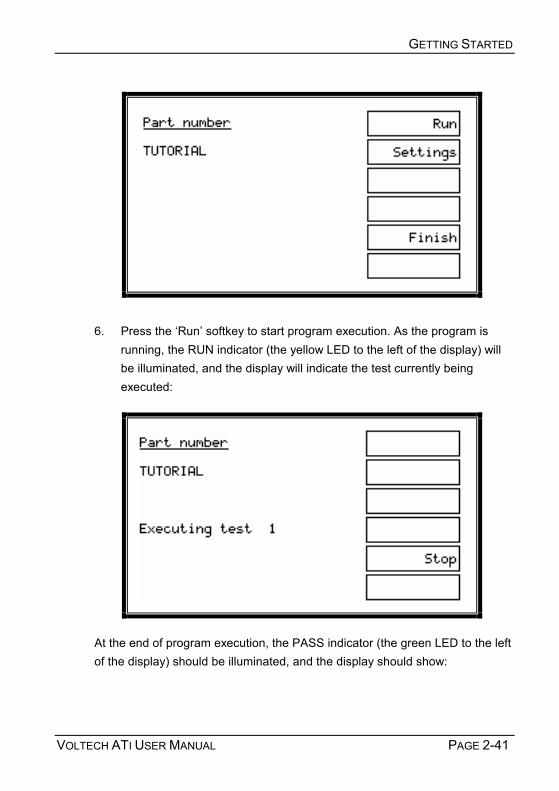
6. Press the Run softkey to start program execution. As the program is running, the RUN indicator (the yellow LED to the left of the display) will be illuminated, and the display will indicate the test currently being executed:
At the end of program execution, the PASS indicator (the green LED to the left of the display) should be illuminated, and the display should show:

GETTING STARTED
PAGE 2-42 VOLTECH ATI USER MANUAL
7. Press the RUN softkey several times to repeat the program execution.
On each run of the program, the test results should be passed back to the Server, where they may be viewed in the On-line Monitor window
If batch statistics have been enabled within the Server, you will see the summary batch results window.

GETTING STARTED
VOLTECH ATI USER MANUAL PAGE 2-43
Test results may also be reviewed at any time via the testers front-panel results listing screen, which is accessible from the Run-Finish display by pressing the Results softkey (see below).
The results listing screen displays all completed tests giving test number, type, result in both value and pass or fail, and status error (for a description of status error codes, see chapter 3). The listing may be printed by pressing the PRINT soft-key in the same style as the standard results.

GETTING STARTED
PAGE 2-44 VOLTECH ATI USER MANUAL
After several program runs, press the Finish softkey to return the tester to the top-level display.
This is the end of the step-by-step tutorial, which forms only a very brief introduction to the features available on your ATi. Please study and browse through the rest of this manual (or the on-line help for the Windows software) to get the best from your transformer tester.
The next section lists more features of the tester that you may wish to investigate yourself at this point, before you try to create real programs for production use.

GETTING STARTED
VOLTECH ATI USER MANUAL PAGE 2-45
2.3.7 Storing Programs For everyday production use, programs should be stored either:
• on a PC running the server software which will be permanently connected to the AT.
• in the testers own memory.
Method 1: Using a permanently connected PC server has been described in the previous Getting Started section.
Method 2: Using the ATis own internal memory as described here:
The programs can be stored within the tester even when it is switched off. Once a program is stored, the tester may be used without PC Editor or Server software.
To operate the tester in this way, the origin of the testers programs must be set to the local program store.
On the tester, at the Program mode display, under the softkey SET-UP, change the Origin to LOCAL.
This is described in section Getting Started
Working Without a Server – Storing a SINGLE Program
A single program may be stored in the AT using the PC Editor.
Once a program has been entered using the Editor and downloaded to the tester, the tester will display:

GETTING STARTED
PAGE 2-46 VOLTECH ATI USER MANUAL
Press Local Save, and the program that has been downloaded from the PC editor will be saved in the testers local program store. Note that any programs previously stored in the tester will be lost.
All PC connections to the tester may now be removed.
To run the program at any time, return the tester to the top-level display, press Programs at the top-level display, choose the program from the list of programs and press the Run key and continue as before.
Storing Groups of Programs Inside the ATi Using the PC Server
Rather than dealing simply with individual programs, the AT Server allows you to create groups of programs, which may be downloaded to the AT tester and then used individually from within the local tester facilities.
Having executed programs from the Server, as it is connected to the tester, you may want to download a group of programs to the tester, so the tester can be used in a stand-alone situation. To do this, use the Server software to create a named group of programs.
Ensure that the Server is still running and connected to the tester, as described above.

GETTING STARTED
VOLTECH ATI USER MANUAL PAGE 2-47
On the tester, at the top-level display, choose Set-Up. Then, at the Set-up display, press the Groups softkey , followed by the List softkey to obtain a list of program groups available for download.
Select the group to be downloaded to the tester and press Enter. If the group download is completed successfully, you will see the following display:

GETTING STARTED
PAGE 2-48 VOLTECH ATI USER MANUAL
At this point, unless you wish to archive measured results on the Server, the Server connection may be removed.
Return to the testers top-level display by pressing the Continue softkey, change the set-up of the tester to use the internal program store instead of the Server, press the Programs softkey, and you will find the downloaded group programs available to you locally on the tester.
Results Analysis
You may wish to use another application for further analysis of test results sent back to the Server:
Close down the Server so that you may have full access to the results file.
The results will be stored in the directory chosen for results when the Server was installed earlier in a file with a name similar to
C2311096.ATR,
where C2311096 is a coded version of the date, and .ATR is the file extension used by the AT Server for results files.
As an example, use the procedure outlined in section 4 of this manual to import the results into an Excel spreadsheet.

GETTING STARTED
VOLTECH ATI USER MANUAL PAGE 2-49
2.4 SELF-TEST
Self-test is a sequence of checks made by the tester to ensure the unit is functioning correctly. Self-test checks that all of the relays in the 20-way matrix are opening and closing properly and checks that all the test signal sources and measuring circuits are working properly and within their calibration limits.
Once the tester has warmed up for an hour, you may run self-test at any time by pressing the SELF-TEST softkey in the top-level menu.
Before commencing self-test, please ensure that there is nothing touching any of the test nodes on the top surface of the tester. In particular, remove all test fixtures and transformers and anything connected to the four BNC terminals. !

GETTING STARTED
PAGE 2-50 VOLTECH ATI USER MANUAL
As the self-test is running, the front-panel display will indicate progress using a horizontal bar:
At the end of the self-test, you should see the following screen:

GETTING STARTED
VOLTECH ATI USER MANUAL PAGE 2-51
If there is a failure at any point in the self-test, you will see a display similar to the one below:
The message shown on the lower two display lines will depend on what caused the failure.
In the unlikely event that your tester continues to fail, please make a careful note of the failure message and error codes, which may be accessed by pressing Details at the above display, and contact your Voltech supplier immediately. (For more detail on AT error codes, see chapter 3.)
GETTING STARTED
PAGE 2-52 VOLTECH ATI USER MANUAL
2.5 PRODUCTION MODE
This is the normal operating mode of the ATi when used for production testing of transformers.
Before you try to use the tester in production mode, make sure that all of the following have been carried out:
1. Test programs have been created for the transformers that you wish to test.
2. Either the programs are archived in the Server, which is connected to the tester and running, and the tester has been set up to use the Server as the Program Store,
or the programs have been downloaded into the tester, which has been set up to use its internal memory as the Program Store.
3. Fixtures have been created for the transformers you wish to test.
Note:
If you have a footswitch fitted to the remote port on the tester, pressing it will take the same action in production mode as pressing the upper softkey.
For text entry (such as the name of a program or the serial number of the transformer under test), you may optionally use a barcode reader connected to the tester's rear panel barcode port.

GETTING STARTED
VOLTECH ATI USER MANUAL PAGE 2-53
2.5.1 Production Mode With No Options Enabled For simple test programs, (where none of the following options are enabled: batch number, operator number or serial number), the flow diagram shown on the left summarizes production mode operation.
Select
Test Program to Run
FixtureCompensation
NOCOMP
Top-levelDisplay
Select Programs Soft-key
Fit Fixture
CompensateFixture?
COMP
RUN-FINISHMenu
Measurements
RUN
Run orFinish?
FINISH

GETTING STARTED
PAGE 2-54 VOLTECH ATI USER MANUAL
At the top-level display, press softkey 1 Programs.
The program to be run may now be chosen from a list of programs available on the PC Server or in the ATis own memory (i.e., local programs), entered by swiping a barcode, or created directly from the front panel by selecting * New program * and pressing the Set-Up softkey (see chapter 6).
Once the test program to be executed has been selected, pressing softkey 1, Run, produces the following display:

GETTING STARTED
VOLTECH ATI USER MANUAL PAGE 2-55
FIXTURE1 is the name given as the Fixture ID in the Editor software Program options dialogue (see chapter 3) or under program options in front-panel program mode (see chapter 6).
Press Compensate or No Comp as required.
Note: For fixture compensation, see later in this chapter.
Place the component to be tested in the fixture and press the Run softkey, touch one of the run-pads, or press the footswitch.

GETTING STARTED
PAGE 2-56 VOLTECH ATI USER MANUAL
After the measurement, remove the component and place it in the Pass or Fail bin, as appropriate.
Continue in this way until each component in the batch has been tested, then press Finish.
2.5.2 Error Messages Server Program Store Error
Possible Causes:
Faulty cable
The cable from the AT Server port to the Server PC has a broken wire or is not plugged in correctly.
COM port
The COM port has not been set up in the Server application.
Server not running
Either the Server PC is not powered on, or the Server application is not running.

GETTING STARTED
VOLTECH ATI USER MANUAL PAGE 2-57
If the Server software and connection to the Server PC are working correctly, the following error screen may appear:
Cause:
The directory set up in the Server application as the location of test programs does not contain a test program file with the requested name. Local Program Store Error

GETTING STARTED
PAGE 2-58 VOLTECH ATI USER MANUAL
Cause:
The requested part number is not resident in the group of programs that have been downloaded into the AT.
At all the above displays, pressing the Continue softkey will take you back to the top-level display.
2.5.3 Indications Displayed While Tests Are Running
Where 1 represents the position of the test within the test program.
The operator may terminate the measurements at any time by pressing the Stop softkey. Alternatively, you may use the STOP input signal on the testers remote port, which may be connected, for example, to an emergency stop switch.
As the measurements proceed, the test number will increment.
GETTING STARTED
VOLTECH ATI USER MANUAL PAGE 2-59
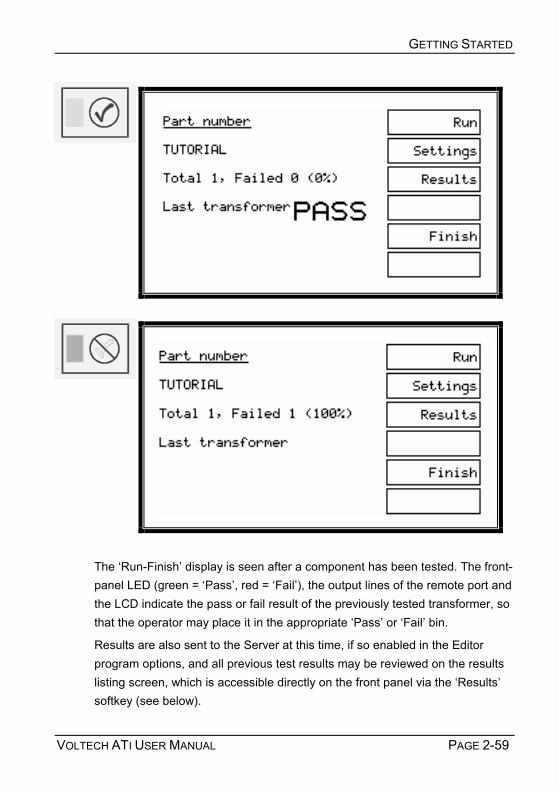
The Run-Finish display is seen after a component has been tested. The front-panel LED (green = Pass, red = Fail), the output lines of the remote port and the LCD indicate the pass or fail result of the previously tested transformer, so that the operator may place it in the appropriate Pass or Fail bin.
Results are also sent to the Server at this time, if so enabled in the Editor program options, and all previous test results may be reviewed on the results listing screen, which is accessible directly on the front panel via the Results softkey (see below).

GETTING STARTED
PAGE 2-60 VOLTECH ATI USER MANUAL
Results listing screen
Note that the total and failed number of transformers tested displayed are reset when the test batch number is changed or a new test program is run.
If the STOP softkey is pressed or the STOP input of the remote port is held low, the ATi will immediately stop testing. STOP will be shown on the display, all LEDs will be off, and no results will be reported back to the Server.
2.5.4 Re-measuring Fixture Compensation

GETTING STARTED
VOLTECH ATI USER MANUAL PAGE 2-61
If you think that fixture compensation needs to be re-measured at any time, at the above display, press the Settings softkey to reveal:
Press Compensate to repeat the fixture compensation measurements, or Back to return to the RUN-FINISH display without re-compensating.
2.5.5 Execute Mode With Options Enabled As stated in the following chapter of this user manual, test programs may be created with any of the following three options enabled or disabled:
• Operator name
• Batch number
• Serial number
In each case, if an option is enabled, the data entered by the operator for that option is included with the results that are sent back to the Server. This additional data is then available to be used as you wish; for example, it may be included in your production reports.
Note that these options are part of the program, not global settings of the ATi, allowing you to enable different options for each transformer, as required.

GETTING STARTED
PAGE 2-62 VOLTECH ATI USER MANUAL
When running programs with any of the above options enabled, there will be additional displays (depending on which options are enabled) after the Fit the Fixture display and before the RUN-FINISH display.

GETTING STARTED
VOLTECH ATI USER MANUAL PAGE 2-63
The following flow diagram summarizes the possibilities:
Top-level Display
SelectPrograms Soft-key
Select Test Program to Run
Fit andCompensate
Fixture
RUN-FINISHMenu
New BatchNew OperatorRe-compensate
FINISHRUN
EnterOperator Name
EnterBatch Number
EnterSerial Number
Measurements
Enter NewSerial Number

GETTING STARTED
PAGE 2-64 VOLTECH ATI USER MANUAL
Additional displays after entering the part number

GETTING STARTED
VOLTECH ATI USER MANUAL PAGE 2-65
Use either the keypad or a barcode reader to enter the operator/batch/serial number, then press the ENTER key on the keypad or the Enter softkey.
Cursor softkeys ( ← → ) appear in context, and may be used with the Delete softkey to correct mistakes.
Serial Number Entry After the First Transformer
When the serial number option is enabled, after the measurements for each transformer have been completed, the following display will be seen (with the fourth display line indicating Pass, Fail or Stop as appropriate):

GETTING STARTED
PAGE 2-66 VOLTECH ATI USER MANUAL
If the next serial number to be used simply follows on in sequence after the previous one, then press the Last + 1 softkey (or the touch pads). This will enter the next serial number automatically and return the display to the RUN-FINISH selection.
Note: Last + 1 will be displayed only if the serial number is of the form:
xxxAnnnn
Where xxx is a field containing any characters, A is a non-numeric character, and nnnn is a field of all numeric characters.
Both xxx and nnnn can be of any length, provided that the total serial number is no more than 20 characters.
When nnnn is all 9s (for example 99), the next number will show nnnn as all 0s (for example 00); the characters xxxA will not be changed.
Alternatively, if the next serial number does not follow from the previous one in sequence, you may use the keypad (or the barcode reader) to type in a new number.
After typing the new number, press the ENTER key, the ENTER softkey or the footswitch to return to the RUN-FINISH display.

GETTING STARTED
VOLTECH ATI USER MANUAL PAGE 2-67
(Again, cursor softkeys ( ← → ) appear in context, and may be used with the Delete softkey to correct mistakes.)
Note: Pressing the Abort softkey will also take you back to the RUN-FINISH display, but with no serial number entered. This would be the correct action if the next softkey you wish to press is FINISH. (Subsequently pressing RUN would merely return you to the Enter the serial number display.)
Re-inputting the Options
When options are enabled, the RUN-FINISH display allows access to additional softkeys that enable you to change the batch number or operator name without having to re-enter the test program name. You may access those additional softkeys via the Settings softkey from the RUN-FINISH display.
To change the batch number, press Settings, and the following display will be revealed. Choose the New Batch softkey to enter a new batch number at this time, or to change the operator name, press the Operator softkey.

GETTING STARTED
PAGE 2-68 VOLTECH ATI USER MANUAL

GETTING STARTED
VOLTECH ATI USER MANUAL PAGE 2-69
2.6 STOP ON FAIL
Stop on Fail is another program option that is either enabled or disabled when the program is created (see chapter 3).
When enabled, it will cause the measurements to be terminated after each test that has produced a Fail result. A display similar to the following will be seen:
This display shows:
1 Part name / number.
2 Failing test number and test mnemonic.
3
Graphical qualification of the failure showing the value measured with respect to the range of legal values, where:
Box Represents the legal limits for the test.
Vertical bar Represents the value measured. (Replaced by an arrowhead to represent higher or lower, when the measured value is significantly outside of the legal range. See notes below.)
4 Value measured, with appropriate units.

GETTING STARTED
PAGE 2-70 VOLTECH ATI USER MANUAL
Note
The third line, showing the graphical comparison of the measured value and test limits, has a logarithmic scale. The measured value may be represented by either a vertical bar (as shown), when it lies within the range that can be displayed on the LCD, or by an arrowhead (< or >), at the end of the horizontal bar, when it lies outside the range that can be displayed on the LCD.
Pressing the Abort softkey stops the program and allows the operator to discard the failing component at the earliest opportunity to minimize test times. (The abort is also reported to the Server when the program option 'Send retry results to server' is enabled and printed out, when a results printing option is set.)
After pressing the Continue softkey, the remaining tests in the program will be executed. Stop on Fail will remain active, and any subsequent test that also fails will produce a similar display. At the end of the measurement, the component will be classed as a Fail.
Pressing the Re-Run softkey will re-start the test sequence from the beginning. You would normally press Re-Run if the failure were caused by the component being incorrectly inserted into the fixture. Unless the option Send retry results to server is enabled, at this point, there will be no data sent back to the Server. Therefore, after you have corrected the mistake, following the re-run, good transformers will be reported as Pass.

GETTING STARTED
VOLTECH ATI USER MANUAL PAGE 2-71
2.7 TRIM
If the TRIM test is included in a program, the behavior in production mode is similar to the Stop on Fail option described above:
If the test before the TRIM test produces a Pass result, then the program proceeds directly to the next test after the TRIM test.
If the test before the TRIM test produces a Fail result, then the front panel display will be similar to the following:
The main difference between this and the Stop on fail display is that the reading on the fourth line will be continuously updated, allowing adjustments to be made to bring the test result within limits.
Pressing the Abort softkey, again, stops the program and allows the operator to throw away a transformer that cannot be adjusted to give a Pass result.
After pressing the Continue softkey, the remaining tests in the program will be executed and, at the end of the measurement, the component will be classed as a Fail.
Pressing the Re-Run softkey will re-start the test sequence from the beginning.

GETTING STARTED
PAGE 2-72 VOLTECH ATI USER MANUAL
Note
After making the necessary adjustments, you must press Re-Run to enable the component to be recorded as a Pass.
If further adjustment is necessary, you may re-run from the start as many times as you like. Unless the option Send Retry Results to Server is enabled, there will be no data sent back to the Server until the measurements for all tests in the program have been completed.
All transformers are capable of generating voltages much higher than the test voltage.
When making adjustments, take care not to touch any transformer terminals, the transformer body, or any exposed metal on the test fixture. Ideally, make sure that you use a trimming tool with a well-insulated handle.
When applying a test signal to a winding, always be mindful of the turns ratio of the transformer that you are testing. Very high voltages can be generated on the other windings of the transformer; if these voltages exceed 250V the tester may be permanently damaged.
!

GETTING STARTED
VOLTECH ATI USER MANUAL PAGE 2-73
2.8 FIXTURE COMPENSATION
The ATs fixture compensation eliminates errors due to stray parasitic components on the fixture board itself. These are usually a combination of parallel capacitance between adjacent wires, sockets or pins, and series resistance and inductance along the lengths of wires.
It is best to try fixture compensation when performing trial runs on the program, as it is being developed, using the Editor. As a guide, if fixture compensation changes the test results, then it should be applied whenever the program is run in a production situation.
For optimum accuracy in production test, fixture compensation measurements should be made:
1. Whenever the test fixture is changed.
2. At the beginning of each day or work period.
3. Whenever a new test program is loaded into the AT for execution
Performing compensation on a fixture consists of making TWO measurements. Short-circuit (S/C) compensation will compensate for the effects of stray connection lead resistance and inductance. Open circuit (O/C) compensation, will compensate for the effects of stray lead capacitance. See also the description of 4-terminal Kelvin connections in the fixture section of this manual for how to eradicate the effects of CONTACT impedance between the test part and the fixture.
To Perform Fixture Compensation
Once a program is ready to run, you will have the option of pressing the COMPENSATE softkey on the panel.
Press COMPENSATE and you will be given the option to perform S/C or O/C compensation. BOTH types of compensation should be performed, one after the other. The order in which S/C and O/C compensation is performed is unimportant.

GETTING STARTED
PAGE 2-74 VOLTECH ATI USER MANUAL
For S/C compensation, first make up a transformer bobbin with shorting links in place of the windings:
To make a shorting bobbin, solder short pieces of wire across the relevant pins (or all of the pins) a spare blank bobbin or complete transformer.
Transformer Shorting Bobbin for S/C compensation
Put the short-circuit bobbin into the fixture and
Press softkey 1 S/C COMP to begin short circuit compensation.
Remove the short-circuit bobbin but leave the fixture in place and
Press softkey 2 O/C COMP to begin open circuit compensation.

GETTING STARTED
VOLTECH ATI USER MANUAL PAGE 2-75
Press softkey 4 NO COMP to abort compensation and begin running the program.
Once you have chosen either S/C compensation or O/C compensation, the ATi will make very accurate measurements of the stray components. A typical S/C compensation measurement might take 10 seconds or more during which time you will see a progress bar on the display:
Following one compensation (and assuming you have performed S/C first), you will be prompted to perform the other compensation (O/C compensation in this case).
Remove the S/C bobbin but leave the fixture in place before performing an O/C comp.
You do not have to perform both types of compensation, but it is always recommended.

GETTING STARTED
PAGE 2-76 VOLTECH ATI USER MANUAL
Should either S/C or O/C compensation display a FAIL, as shown above, check:
• The short-circuit connections (for S/C compensation).
• That there are no erroneous shortcircuits on the fixture.
• That the fixture is properly seated and locked down into the fixture bay. Then retry the compensation.
• That for each node that is used, the fixture short-circuits power and sense together when there is no test piece in place.
One compensation has been successfully completed, the compensation values are stored within the AT until a new program is loaded, the tester is switched off or compensation is re-run.
Test programs can be run without fixture compensation being performed, but this may affect the accuracy of the results, depending upon the type of transformer being tested and the fixture design.

GETTING STARTED
VOLTECH ATI USER MANUAL PAGE 2-77
2.9 SET-UP MODE
Set-up mode has two main functions:
To change the tester's set-up options (including setting up for Server operation) and to download a group of programs from the Server PC to the tester's internal memory.
To access set-up mode from the top-level menu (see above), press the Set-Up softkey to change to the following display:

GETTING STARTED
PAGE 2-78 VOLTECH ATI USER MANUAL
The two main functions of set-up mode each have their own softkeys at this display. Press the Groups softkey to download a group of test programs from the Server to the tester's internal memory; or press the Set-Up softkey to change any of the testers set-up options.
Pressing EXIT at this point will return the tester to the top-level display.
2.9.1 Set-up Softkey Pressing the softkey Set-Up at the Set-Up mode display shown above will reveal:
This display is the start of a list of options under the title Set-Up.
To modify an option:
Press the cursor softkeys ( ↑ and ↓ , which appear in context) to scroll up and down the list, so that the option you wish to modify is positioned on the third line.
For most options, press the third softkey to cycle round the available settings for that option. In the example of Pass Beeper, this will be:
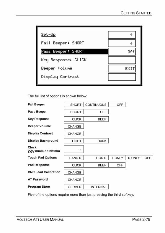
GETTING STARTED
VOLTECH ATI USER MANUAL PAGE 2-79
The full list of options is shown below:
Fail Beeper SHORT CONTINUOUS OFF
Pass Beeper SHORT OFF
Key Response CLICK BEEP
Beeper Volume CHANGE
Display Contrast CHANGE
Display Background LIGHT DARK
Clock: yyyy mmm dd hh:mm →
Touch Pad Options L AND R L OR R L ONLY R ONLY OFF
Pad Response CLICK BEEP OFF
BNC Lead Calibration CHANGE
AT Password CHANGE
Program Store SERVER INTERNAL
Five of the options require more than just pressing the third softkey.

GETTING STARTED
PAGE 2-80 VOLTECH ATI USER MANUAL
Beeper Volume
Pressing the softkey Change brings up an additional display:
Press the ↑ and ↓ softkeys until the beeper makes the level of sound you require, then press the EXIT softkey to return to the set-up list.
Display Contrast
The additional option display is very similar to the beeper volume display, again with ↑ and ↓ softkeys, which this time adjust the display contrast.
To change the display background, select LIGHT or DARK. LIGHT has been chosen as the default setting, as this will provide the clearest display across a broad range of contrast settings and ambient temperature.
Clock
There are five fields to set up:
Initially, the cursor will be in the first field - yyyy - which is the year. Type the number you require using the keyboard, and press either the ENTER key ( ↵ ), or the → softkey to move to the next field.
For the second field - mmm -, which is the month, the softkeys change to give the names of each month. Press the appropriate softkey to select which month.

GETTING STARTED
VOLTECH ATI USER MANUAL PAGE 2-81
The remaining fields - dd, hh and mm (day, hour and minute) are changed in the same way as the year, using the number pad.
BNC Lead Calibration
For optimum measurement accuracy in LCR mode using the BNC leads, calibration factors are stored within the ATi. This calibration is set at the factory for the BNC leads supplied with the ATi and it is not normally necessary to adjust this calibration.
If the leads are replaced by others or modified in any way then the leads should be re-calibrated.
To calibrate the leads, press the softkey 'Change' when BNC lead calibration is selected.
Note that you will need a nominal 750-Ohm resistor later in the process. A typical 680 ohm 1/4 watt resistor will be sufficient. The exact value of the resistor is not important to this process, but you must use exactly the same resistor whenever it is required during this process.
The BNC calibration process consists of six measurements: an open-circuit, short-circuit and 750 ohm measurement across nodes 13 and 15 on the fixture and then the same measurements made using the BNC leads.

GETTING STARTED
PAGE 2-82 VOLTECH ATI USER MANUAL
• Press 'Continue', short together nodes 13 and 15 on the fixture and press 'Continue' again to make the first measurement which is a short-circuit compensation.
• Next remove the short, but ensure that the power and sense terminals are short-circuited together on nodes 13 and 15. Press 'Continue' to run a short-circuit compensation.
• Next connect the nominal 750-Ohm resistor between node 13 and 15 and press 'Continue'.
Next the process is repeated using the BNC leads.
• A short-circuit compensation on the BNC leads.
• An open-circuit compensation on the BNC leads.
• A measurement of the 750-Ohm resistor using the BNC leads.
At the end of the process, press 'continue' to save the new calibration factors or press 'Abort' to discard them and return to the previously stored calibration.
You may press the 'Abort' softkey at any time to stop the process and discard changes.

GETTING STARTED
VOLTECH ATI USER MANUAL PAGE 2-83
AT Password Pressing the Change softkey, brings up the following display:
Enter the new AT password via the instrument keypad, using the Shift softkey to activate letter entry, if necessary. Press Enter to confirm the new password.
Resetting Tester Set-Up Options Please note that pressing the decimal point (.) on the instrument keypad

GETTING STARTED
PAGE 2-84 VOLTECH ATI USER MANUAL
during boot-up at the general information screen will reset all tester options to the factory defaults, including screen contrast, screen background and beep volume, excluding the real-time clock.
The factory default settings are:
Option Default Setting FAIL Beeper OFF PASS Beeper OFF Key Response CLICK Beeper Volume 6 Display Contrast 8 Display Background LIGHT Touch Pad Option L AND R Pad Response CLICK Program Store INTERNAL
2.9.2 Groups Softkey When the tester is set up to use the INTERNAL program store, and after you have entered the part name, it will search for that name in the programs that are stored in its own, non-volatile RAM. To store these programs, you must use either the group download or 'tester download' features described here.
Group Download Using the Server
Before attempting to download a group of programs, ensure that the Server software is running on its PC, that the lead is connected from the tester's Server port to the Server PC, and that the COM port is correctly set up in the Server.
Also ensure that the group you wish to use has been created within the Server. (From the Server top-level menu, select Setup, Groups, etc., as explained in chapter 4).
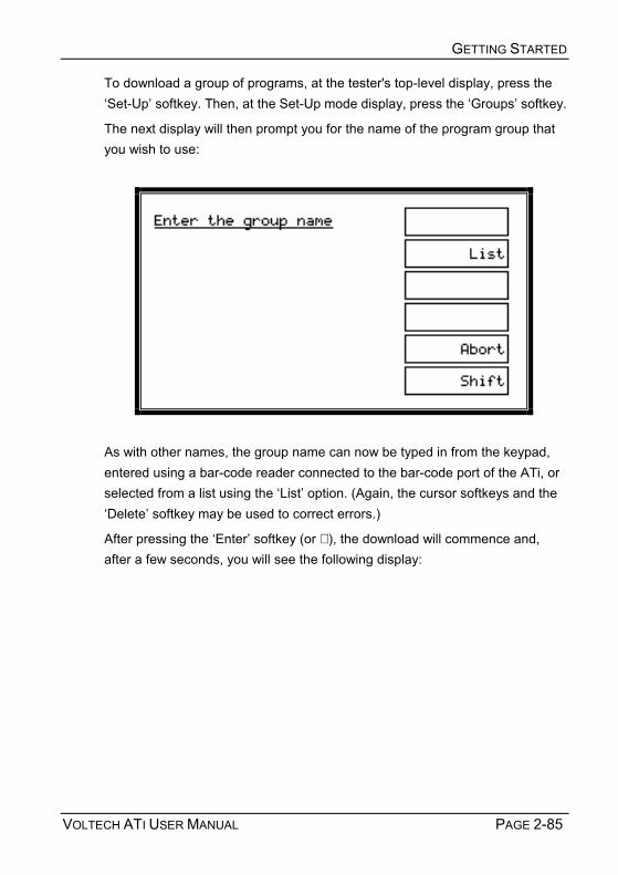
GETTING STARTED
VOLTECH ATI USER MANUAL PAGE 2-85
To download a group of programs, at the tester's top-level display, press the Set-Up softkey. Then, at the Set-Up mode display, press the Groups softkey.
The next display will then prompt you for the name of the program group that you wish to use:
As with other names, the group name can now be typed in from the keypad, entered using a bar-code reader connected to the bar-code port of the ATi, or selected from a list using the List option. (Again, the cursor softkeys and the Delete softkey may be used to correct errors.)
After pressing the Enter softkey (or ↵ ), the download will commence and, after a few seconds, you will see the following display:

GETTING STARTED
PAGE 2-86 VOLTECH ATI USER MANUAL
Press Continue to return to the top-level display. Your program group has now been loaded into the testers internal store and the Server PC may be disconnected. These programs will be saved during power off, and will only be overwritten by another group download.
Group Download Error Messages
The following is a list of possible error messages that may occur if there is a fault in the group download process, together with suggestions for the possible cause.
a)

GETTING STARTED
VOLTECH ATI USER MANUAL PAGE 2-87
Possible Causes:
Faulty cable The cable from the testers Server port to the Server PC has a broken wire, or is not plugged in correctly. COM port The COM port has not been set up in the Server application. Server not running Either the Server PC is not powered on, or the Server application is not running.
b)
Possible Cause:
The directory set up in the Server application as the location of test programs does not contain a group with the requested name.
At all the above displays, pressing the Continue softkey will take you back to the top-level display.
Press Continue to return to the top-level display. Your program group has now been loaded into the testers internal store and the Server PC may be

GETTING STARTED
PAGE 2-88 VOLTECH ATI USER MANUAL
disconnected. These programs will be stored during power off, and will only be overwritten by another group download.
Tester Download Using The Editor
A single program may be stored in the AT using the Editor PC.
Once a program has been entered using the Editor and downloaded to the tester, the tester will display:
Press Local Save and the program that has been downloaded from the PC Editor will be saved in the testers local program store. Note that any programs previously stored in the tester will be lost.
All PC connections to the tester may now be removed.

VOLTECH ATI USER MANUAL PAGE 3-1
3 PROGRAM EDITOR

PROGRAM EDITOR
PAGE 3-2 VOLTECH ATI USER MANUAL

PROGRAM EDITOR
VOLTECH ATI USER MANUAL PAGE 3-3
Contents – Program Editor
3.1. CREATING A PROGRAM ........................................................................3-5 3.2. CREATING THE TRANSFORMER SCHEMATIC...........................................3-6
3.2.1. ADDING A TRANSFORMER WINDING ........................................................... 3-7 3.2.2. CONNECTING THE WINDING TERMINALS TO NODES ..................................... 3-8 3.2.3. DELETING A WINDING............................................................................... 3-8 3.2.4. RENAMING A TERMINAL ............................................................................ 3-9 3.2.5. ADDING A TERMINAL TO AN EXISTING WINDING ......................................... 3-10 3.2.6. DELETING A TERMINAL FROM AN EXISTING WINDING ................................. 3-11 3.2.7. ADDING A CORE CONNECTION ................................................................ 3-11 3.2.8. DELETING A CORE CONNECTION ............................................................. 3-11 3.2.9. ADDING A SCREEN CONNECTION ............................................................. 3-12 3.2.10. DELETING A SCREEN CONNECTION.......................................................... 3-12
3.3. CREATING THE TEST PROGRAM..........................................................3-13 3.3.1. SETTING THE PROGRAM OPTIONS ........................................................... 3-14 3.3.2. ADDING TESTS ...................................................................................... 3-21 3.3.3. INSERTING TESTS .................................................................................. 3-22 3.3.4. MODIFYING TESTS ................................................................................. 3-24 3.3.5. DELETING TESTS ................................................................................... 3-25 3.3.6. TEST PARAMETERS................................................................................ 3-26 3.3.7. TEST LIMITS .......................................................................................... 3-27
3.4. USING THE MEASURE BUTTON............................................................3-31 3.4.1. HARDWARE CONNECTIONS FOR USING THE MEASURE BUTTON .................. 3-31 3.4.2. EXAMPLE OF USING THE MEASURE BUTTON WITH THE LS TEST ................. 3-32 3.4.3. RESTRICTIONS FOR AUTOMATICALLY OBTAINING TEST PARAMETERS .......... 3-38 3.4.4. VERIFYING YOUR PROGRAM ................................................................... 3-39
3.5. ERROR CODES...................................................................................3-42

PROGRAM EDITOR
PAGE 3-4 VOLTECH ATI USER MANUAL
3.5.1. FRONT-PANEL ERROR CODES................................................................. 3-43 3.5.2. EDITOR ERROR CODES .......................................................................... 3-43
3.6. FIXTURE COMPENSATION (SEE ALSO SECTION 2.8).......................... 3-46 3.7. PROGRAMMING HINTS AND TIPS......................................................... 3-48

PROGRAM EDITOR
VOLTECH ATI USER MANUAL PAGE 3-5
3.1 CREATING A PROGRAM
Using the Editor enables you to quickly and easily create test programs for your AT Series Tester without any specialized knowledge of computer programming.
The Editor will guide you through the programming of the tests you wish to carry out, helping you ensure that programming errors are eliminated.
• The features of the Editor Software editor include :
• Full MS Windows application compatibility, providing many visual aids for tailoring the test parameters to your needs.
• Schematic diagrams of the transformer under test showing pin to node connections. These form the basis of your test program.
• Form fill-in dialogue boxes to guide you through the programming of each test.
• A test program under development may be executed and the test results viewed on screen.
• Test programs and results may be stored in a PC running the Server software.
• Transfer of test programs to specified paths or floppy disk for backup.
• A full context sensitive and menu driven help system.
An additional function available through the test program editor is upgrading the firmware of your AT Series Tester. See the Firmware Upgrades section in chapter 2 for details

PROGRAM EDITOR
PAGE 3-6 VOLTECH ATI USER MANUAL
3.2 CREATING THE TRANSFORMER SCHEMATIC
The Voltech AT Series Schematic Editor allows you to recreate the configuration of the transformer on the fixture as a schematic diagram on the screen. Once the way in which the ATs nodes are connected to the transformer pins has been entered into this schematic you can create test programs without having to refer to the testers node numbers.
This section describes how to create a transformer schematic using the AT Series Schematic editor.
How to:
• Create or add a transformer winding
• Connect the winding terminals to test nodes
• Delete a winding
• Rename a terminal
• Add a terminal
• Delete a terminal
• Add a core connection
• Delete a core connection
• Add a screen connection
• Delete a screen connection

PROGRAM EDITOR
VOLTECH ATI USER MANUAL PAGE 3-7
3.2.1 ADDING A TRANSFORMER WINDING To add a transformer winding onto the screen:
1. Select Add Winding from the Schematic menu on the menu bar.
2. Place the winding on the screen: A selected winding will now be displayed attached to the mouse pointer on the screen. You must decide which half of the screen to place the winding. On crossing the mid-point of the screen, the winding is mirrored to face the nearest test nodes. Click the left mouse button to place the winding.
3. Name the winding terminals:
2. When the winding is placed, a dialogue box appears prompting you to name both of the windings two terminals.
4. You may move the cursor focus between the fill-in boxes by using the TAB key or by pointing and clicking with the mouse.
5. When both terminals have been named, you should press ENTER on the keyboard or click on OK with the mouse in the dialogue box.
6. To make a winding with more than two terminals, see Adding a terminal to an Existing Winding, later in this chapter. NOTE: Terminal names may be between 1 and 6 characters in length, and may contain any upper case letter or AT Series keyboard character excluding SPACE.
i

PROGRAM EDITOR
PAGE 3-8 VOLTECH ATI USER MANUAL
3.2.2 CONNECTING THE WINDING TERMINALS TO NODES To connect the winding terminals to test nodes:
1 Select a terminal to connect with the RIGHT mouse button.
2 Keeping the right button pressed, drag the wire to the selected test node.
3 When the mouse pointer is over the test node, release the mouse button.
4 The connection may also be made in reverse by first selecting the test node and then connecting it to the winding terminal.
To change a connection, simply use the right button to pick it up and move it to either another test node or to another transformer terminal.
To delete a connection, again use the right mouse button to pick up the connection, but this time release it when it is not over either a node or a terminal.
3.2.3 DELETING A WINDING To delete a winding:
1. Select a winding by pointing at it with the mouse pointer and clicking the left mouse button once. A selected winding will be indicated by a box surrounding the winding.
2. Choose Delete Winding from the Schematic menu.
The selection will be removed from the screen.
Note that ALL tests containing the deleted terminals will also be DELETED.

PROGRAM EDITOR
VOLTECH ATI USER MANUAL PAGE 3-9
3.2.4 RENAMING A TERMINAL To rename a terminal either:
1. Select the winding containing the terminal to rename by using the mouse pointer and clicking the left mouse button.
2. Choose Rename Terminals from the Schematic menu
OR use the mouse pointer and double click on the chosen winding.
A fill in dialogue box will appear. Each fill-in box will contain the current names of the winding terminals.
You may change a name by:
1. Selecting the appropriate terminal box with the mouse, or by moving between the boxes with the TAB key on the keyboard and then typing the new name.
2. Pressing ENTER or clicking the mouse pointer on OK
The dialogue box will be removed and the corrections will be displayed on the screen.
Note that ALL tests containing the renamed terminals will be DELETED.

PROGRAM EDITOR
PAGE 3-10 VOLTECH ATI USER MANUAL
3.2.5 ADDING A TERMINAL TO AN EXISTING WINDING To add a terminal to a transformer winding:
1. Select Add Winding from the Schematic menu on the menu bar to create a second two terminal winding.
2. Now place the new winding on the same side of the schematic as the winding that requires the additional terminal.
Upon clicking the left mouse button, a form fill-in dialogue box will appear on the screen with prompts to insert the terminal names of the new winding.
3. Name the terminals of the second winding, giving one terminal the same name as a terminal of the previous winding.
4. Press ENTER or click on OK.
The dialogue box will be removed, and the schematic will show the two windings joined at the common terminal.

PROGRAM EDITOR
VOLTECH ATI USER MANUAL PAGE 3-11
3.2.6 DELETING A TERMINAL FROM AN EXISTING WINDING To remove a terminal from a transformer winding:
1. Select the terminal which you would like to be removed by using the mouse pointer and clicking the left mouse button once.
2. Choose Delete Winding from the Schematic menu on the menu bar.
The bottom terminal of the winding will be removed from the screen, together with any connections to that terminal that are present.
Note that ALL tests containing the deleted terminals will also be DELETED.
3.2.7 ADDING A CORE CONNECTION To add a core connection:
Choose Add Core Connection from the Schematic menu.
A connection from the core will appear on the screen. You may now add a core-to-node connection.
3.2.8 DELETING A CORE CONNECTION To delete a core connection:
1. Select the core connection you wish to delete by left-clicking on it with the mouse.
2. Choose Delete Core Connection from the Schematic menu.
3. The connection from the core will be removed from the schematic.
Note that ALL tests containing the deleted core will also be DELETED.

PROGRAM EDITOR
PAGE 3-12 VOLTECH ATI USER MANUAL
3.2.9 ADDING A SCREEN CONNECTION To add a screen connection:
Choose Add Screen Connection from the Schematic menu.
A connection from the screen will appear on the schematic. You may now add a screen-to-node connection.
3.2.10 DELETING A SCREEN CONNECTION To delete a screen connection:
1. Select the connection you wish to delete by pointing at it with the
8. ouse prompt and pressing the left mouse button.
2. Choose Delete Screen Connection from the Schematic menu.
The screen connection will be removed from the schematic.
Note that ALL tests containing the deleted screen will also be DELETED.

PROGRAM EDITOR
VOLTECH ATI USER MANUAL PAGE 3-13
3.3 CREATING THE TEST PROGRAM
This section describes the procedures used when creating the test program with the AT Series Editor.
By the end of this section, you will be able to:
• Set up the program options
• Add a test to the program
• Insert a test in the program
• Modify an existing test in the program
• Delete a test
• Use the measure button to create test parameters
• Verify the program - including fixture compensation

PROGRAM EDITOR
PAGE 3-14 VOLTECH ATI USER MANUAL
3.3.1 SETTING THE PROGRAM OPTIONS Overview
After you have created the program schematic, and before starting to insert any tests in the program, you should set up which program options you would like to use. From the top-level menu bar, select:
Program > Options
You will then see the following dialogue box:

PROGRAM EDITOR
VOLTECH ATI USER MANUAL PAGE 3-15
You may now set up any of the following options by simply clicking with the left button of the mouse: Results Printing Printed reports may be obtained from the printer port of the tester as follows: There will be no results printed out during the test execution.
Failures Only The results of the tests producing a fail result will be printed.
Full Reporting The results for all the tests in the program will be printed out for each transformer tested.
Operator Numbering During program execution, the operator will be prompted to enter his or her identity code. All results will then be tagged with this code.
Batch Numbering During program execution, the operator will be prompted to enter a batch number, which will be attached to the test results.
Serial Numbering During program execution, the operator will be prompted to enter a serial number for each transformer. The number will then be attached to the results for the next transformer tested.
Send Results to Server Select this option if you wish to have the tester send all the measurement results back to the Server PC for archive or analysis.
Send Retry Results to Server
Enable this function if you wish the Server to contain the results from the additional measurements associated with re-running a program, for example after execution has been halted by the STOP ON FAIL program option.
Stop on Fail Select this option to give the fastest test throughput. During program execution, only transformers that produce a pass result will be fully tested; failures will be rejected at the earliest opportunity.

PROGRAM EDITOR
PAGE 3-16 VOLTECH ATI USER MANUAL
Date and Time on Reports
Select this option to have the reports date and time tagged.
AQL (Acceptable Quality Level)
Settings for production test are defined here. AQL is the level of test failures in a batch that are acceptable. Exceeding the AQL is an indication that there is a problem with the quality of the production process or the quality of materials that are being used. AQL monitoring is an optional feature of the Voltech PC Server, which displays live summary results from multiple AT testers. When the AQL set here is reached or exceeded, the Server will display a warning. Both types of AQL limits may be used at the same time. Reaching any one limit will cause a warning to be displayed on the Server.
For further details, see the AT Server section of this manual.
AQL No. of Parts This is the number of failures in the batch at which a warning will be displayed on the Server. This is most often used when the batch size is always similar, or zero / very small numbers of defects are expected.
AQL % of Parts This is the percentage level of failures at which a warning will be displayed on the Server. Note that this AQL is only applied after sufficient parts have been tested to make the percentage meaningful. When setting AQL % of Parts to be 1%, for example, a warning will only be displayed after 100/1 = 100 parts have been tested.
Fixture ID Finally, you should enter a fixture name.
The Fixture ID can be up to 20 characters long. You may use any of the characters that appear on the tester's keyboard:
A ... Z (upper case only)
0 1 2 3 4 5 6 7 8 9 . - / ( ) and 'space'

PROGRAM EDITOR
VOLTECH ATI USER MANUAL PAGE 3-17
When the test program is run on the AT Series Tester, the operator will be prompted to fit the fixture with this name. This will help to make sure that the correct fixture is used.
Note that the fixture name does not have to be the same as the program (part) name. This makes it possible to have one fixture common to a number of transformers, which may, for example, have the same arrangement of pins, but have different windings requiring different test programs.
External AC Source This option is applicable to the AT3600 only.
When you have selected all the required options, click on the OK button to return to the Top Level menu.
Stop on Fail
With this function enabled, the tester will stop program execution whenever a fail is detected, rather than carrying out all the tests in the test program and reporting the passes and fails at the end.
This enables the user to quickly identify a faulty transformer and replace it with another before all the tests have been carried out, thus speeding up the test process.
When a fail is encountered, the tester will display a warning screen and stop the program. The display will inform the user of a test failure, and indicate which limits have been exceeded.

PROGRAM EDITOR
PAGE 3-18 VOLTECH ATI USER MANUAL
An example of this display for an inductance test is shown below.
From this display, after you have pressed the CONTINUE softkey, the tester will execute the remaining tests in the program, and the transformer will be recorded as a fail. (If any further tests fail, then there will be another display similar to the one above for each failing test.)
If you simply wish to throw away the failing transformer at the earliest opportunity, then press the ABORT softkey to terminate this program run, and return to the RUN-FINISH display, from where you can start the program again for the next transformer in the batch.
Alternatively, you may use the RE-RUN softkey if, for example, the failure is due to the fact that the transformer is not correctly inserted in the test fixture. In this case, program execution starts again, and the transformer will receive a pass, if the only fault was that it had been wrongly inserted at the first attempt.
Vertical bar Represents the value measured
Box Represents the user programmable limits for the test

PROGRAM EDITOR
VOLTECH ATI USER MANUAL PAGE 3-19
After you have pressed the RE-RUN softkey, the tester will then be executing a retry. When results are sent to the Server, unless you have enabled the program option Send Retry Results to Server, then no result will be sent to the Server Results File except those for the final execution run, i.e. the one that produces the pass or fail front panel display.
If you wish to see the measured results from each retry in your Server Results File, then you should enable the program option Send Retry Results to Server when the program is created in the Editor. This option could provide data, for example, which allows you to improve your production process and yield.
Notes
1. The third line showing the graphical comparison of the measured value and user programmable limits has a logarithmic scale. The measured value may be represented by either a vertical bar (as shown) when it lies within the range that can be displayed on the LCD, or by an arrowhead (< or >) at the end of the horizontal bar when it lies outside the range that can be displayed on the LCD.
2. Should the tester be returning results to a PC running the Editor software, then the Editor software will freeze when this screen is displayed until the appropriate softkey (Re-run, Continue or Abort) is pressed.
Program Edit
After you have created the program schematic, and selected the program options, you may then start creating the actual program of tests.
To edit the test program, you must first switch to the Program Editor.
From the Top Level menu bar, select:
Program > Edit

PROGRAM EDITOR
PAGE 3-20 VOLTECH ATI USER MANUAL
You will now see a display with three separate windows:
Top Left: A simplified view of the transformer schematic omitting the wiring to the nodes.
This is a passive window intended to be used as a memory aid; it cannot be used to change the schematic. (If you need to alter the schematic at any time, simply click on Schematic then 'Edit' in the top-level menu.)
Bottom Left: The Program Window
This is the list of tests that currently make up the test program.
Normally, for a new program, this window would initially be empty. The display above shows the program of one resistance test created in the Quick Start Tutorial.
Right: The Available Tests Window
This is the list of tests that are available to be used in creating or modifying the test program.
From this display, you may now create the test program suitable for your transformer by adding tests to the program from the

PROGRAM EDITOR
VOLTECH ATI USER MANUAL PAGE 3-21
Available Tests list. The following sections describe how to do this.
3.3.2 ADDING TESTS A test program is a list of tests chosen from the Available Tests list. To create a new program, you simply add tests to the list.
To add a test, use the mouse to select the test you require from the Available Tests list, and double click on that test with the left button.
This will open the dialogue box particular to that test. You simply fill in all the fields of the dialogue box, and then click on the OK button. The test will be added at the end of the Program.
As an example, if you wish to add another R Winding Resistance to the program:
Double click on the R Winding Resistance test in Available Test list.

PROGRAM EDITOR
PAGE 3-22 VOLTECH ATI USER MANUAL
Fill in the fields of the dialogue box.
Click on the OK button.
You will now see this test added to the Program:
3.3.3 INSERTING TESTS
Normally, if you are creating a new test program, you would add the tests in the correct order of execution, as described in the previous section. You would also use this procedure for modifying an existing program, if you needed to append further tests at the end.
However, if you wish to add an extra test somewhere in the middle of an existing program, a different procedure is required:
1. In the Available Tests window, click with the left button of the mouse to highlight the test you wish to insert.
2. In the Program window, click with the left mouse button to highlight one of the existing tests in the list. This will become the point of insertion; the new test will be inserted in front of the one you have selected.

PROGRAM EDITOR
VOLTECH ATI USER MANUAL PAGE 3-23
3. From the top-level menu bar, select:
Program > Insert Test
In this example, a Turns Ratio test will be inserted before the Inductance test 3 in the Program.
You will now see the dialogue box for the test you wish to insert.
4. Enter the appropriate test data in the fields of the dialogue box, and click on OK.

PROGRAM EDITOR
PAGE 3-24 VOLTECH ATI USER MANUAL
You will now see the new test inserted into the program.
3.3.4 MODIFYING TESTS As part of creating a new test program, you would normally experiment by running it with a sample batch of transformers. At this point, you may find that some tests need to be modified, a typical example being that you need to change the test limits.
With the Editor software, modifying a test is very simple.
1. In the Program list window, double-click with the left mouse button on the test you wish to modify. This will re-open the dialogue box for that particular test.
2. Make any changes you require to the test data in the fields of the dialogue box, and click on OK.
You will now see the test with the modified data in the Program window.

PROGRAM EDITOR
VOLTECH ATI USER MANUAL PAGE 3-25
3.3.5 DELETING TESTS To delete a test from the Program with the Editor software is very simple.
1. In the Program list window, click with the left mouse button to highlight the test you wish to delete.
NOTE: Take care to correctly select the test to be deleted, as the Editor software will permanently delete the test.
2. From the top-level menu bar, select:
Program > Delete Test
3. Confirm your selection by clicking Yes in the following dialogue box:
You will now see that the test has been removed from the list in the Program window.

PROGRAM EDITOR
PAGE 3-26 VOLTECH ATI USER MANUAL
3.3.6 TEST PARAMETERS Some tests such as the R-Winding Resistance test (as used in the quick start tutorial chapter 2) are relatively simple to program because you do not have to set up any test conditions. This is not the normal case.
The LS - Winding Inductance (series circuit) - test is more typical, requiring the test parameters Signal and Frequency to be specified.
For many tests, including the LS test, you may enter the Test Parameters in two ways: either by simply keying in the numbers you require, or by using the Measure button.
Clearly, you would type in the test parameters if, for example, they have been specified by the designer of the transformer. If you are not sure what values to

PROGRAM EDITOR
VOLTECH ATI USER MANUAL PAGE 3-27
use, some guidance is given in chapter 7 (Tests & Test Conditions) later in this manual.
If you are using the Measure button to enter limit values, as described in the section later in this chapter, you may also at the same time have the AT Series Tester enter the recommended test parameter values.
To do this in the case of the LS test, you simply leave the Signal and Frequency edit boxes empty at the time you click on the Measure button. If you choose either the mV or V unit button before clicking the Measure button, the test signal determined by the tester will be entered as a voltage; alternatively if you choose the mA units button before clicking the Measure button, the test signal determined by the tester will be entered as a current.
Note that not all tests allow the test parameters to be chosen by the tester.
The programming details for each test in section 7 (Tests and Test Conditions) of this chapter specify which tests allow the Measure button to enter the test parameter values.
3.3.7 TEST LIMITS In the Quick Start Tutorial (chapter 2), it was stated that for the R - Winding Resistance - test the limits could be entered in four different ways. The R test is not unique in this respect. In fact, most tests have several ways in which the limits may be entered, allowing you greater flexibility in configuring each test to match your production testing requirements.
The four types of limits for the R- Winding Resistance test are:
% The limits are entered as positive and negative percentages about a nominal value.
> < The limits are entered as minimum and maximum values.
> There is only a minimum limit.
< There is only a maximum limit.

PROGRAM EDITOR
PAGE 3-28 VOLTECH ATI USER MANUAL
The corresponding dialogue boxes are as follows:
% limits
Minimum and maximum limits (><)

PROGRAM EDITOR
VOLTECH ATI USER MANUAL PAGE 3-29
Minimum limit only (>)
Maximum limit only (<)

PROGRAM EDITOR
PAGE 3-30 VOLTECH ATI USER MANUAL
Many of the tests available for the AT Series have all four limit types. There are obviously some tests where it is not sensible to have four limits types, IR - insulation resistance - being a clear example where only a minimum limit is applicable, as the perfect insulation between windings has no upper limit to its resistance.
To choose which type of limit you wish to use, simply use the mouse to click on one of the buttons % , > < , > or < .
After you have entered the limits in one form, you may change to another form of limits by clicking with the mouse on another one of the radio buttons.
Note: If you are using minimum and maximum limits (><), the values of your minimum and maximum limit cannot be the same, or you will be prompted by an error message to change one or both of your limit values.

PROGRAM EDITOR
VOLTECH ATI USER MANUAL PAGE 3-31
3.4 USING THE MEASURE BUTTON
While working through the Quick Start Tutorial (chapter 2), you may have noticed that the dialogue box for the test R - Winding Resistance - contained a button labeled Measure.
In fact, most tests have a Measure button within the dialogue box. It is included there to allow you to fill in various fields in the dialogue box by using the AT to measure the value from a sample transformer.
All tests with a Measure button will allow you to enter a value into the test limits section of the dialogue box.
In addition, some tests can also make use of the Measure button to select the test conditions. The programming details for each test in section 7 "Tests and Test Conditions" specify which tests allow the Measure button to enter the test parameter values.
3.4.1 HARDWARE CONNECTIONS FOR USING THE MEASURE BUTTON Before attempting to use the Measure button:
1. Make sure you have connected your tester's Auxiliary Port (on the rear panel) to a suitable COM Port on your PC. (This may be COM Port 2, if your mouse is already using COM Port 1.)
2. Set up the COM Port on the PC.
From the top-level menu, select: Setup > Communications In the dialogue box, select the PC communications port that is connected to the transformer tester.
WARNING: If the chosen ‘COM’ port is reserved by another Windows application, an error message will appear. You should select another port.
3. Fit the appropriate fixture to the tester.
i

PROGRAM EDITOR
PAGE 3-32 VOLTECH ATI USER MANUAL
4. Have available both a sample transformer, and possibly a shorting header if you wish to add tests to the program for which you will be applying short-circuit compensation.
. 3.4.2 EXAMPLE OF USING THE MEASURE BUTTON WITH THE LS TEST LS - Winding Inductance (Series Circuit) - is one of the tests where both the test voltage and frequency, and the actual measurement may be obtained by using the Measure button. The following example assumes that this is what you wish to do.
Initially select the LS test in the normal way by double-clicking with the mouse in the Available Tests list.
In the LS test dialogue box:
Enter the terminal names in the normal way.
Select the integration you require if different from the default setting of Medium.
In the Test Parameters section, leave both the Signal and the Frequency edit boxes blank.
The default units button for the Signal is mV. With this setting, the Editor will enter the test voltage chosen by the tester, changing as appropriate to the V button if the signal is large. Alternatively, if you wish the test signal to be determined as a current, click on the mA units button.
Finally, in the lower section of the dialogue box, select the desired limits type.

PROGRAM EDITOR
VOLTECH ATI USER MANUAL PAGE 3-33
At this point, the dialogue box should be as follows:
Now, using the mouse, click on the Measure button.
Because the LS test is one where compensation can be applied, you will then see the following message:
Disable Compensation will stop this dialogue being displayed for subsequent presses of the 'Measure' button for this program only. Disable Compensation does not stop you being offered the opportunity to compensate the fixture for all tests when the complete program is downloaded to the ATi later.
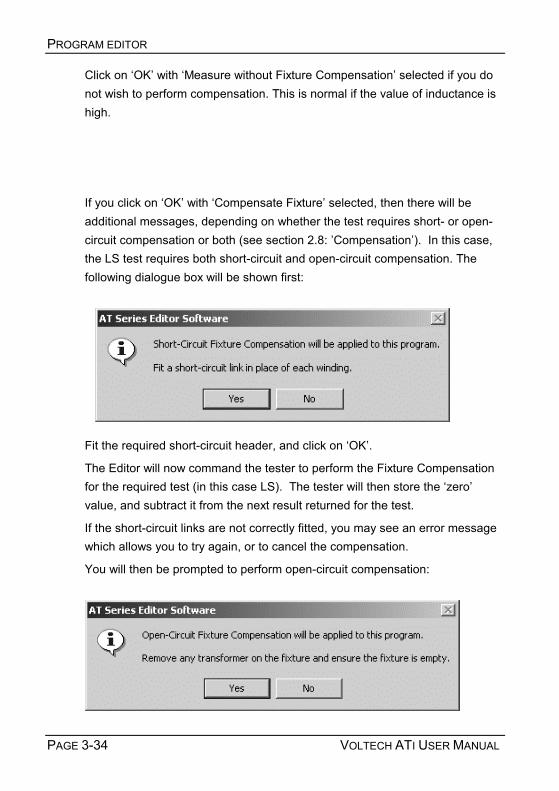
PROGRAM EDITOR
PAGE 3-34 VOLTECH ATI USER MANUAL
Click on OK with Measure without Fixture Compensation selected if you do not wish to perform compensation. This is normal if the value of inductance is high.
If you click on OK with Compensate Fixture selected, then there will be additional messages, depending on whether the test requires short- or open-circuit compensation or both (see section 2.8: Compensation). In this case, the LS test requires both short-circuit and open-circuit compensation. The following dialogue box will be shown first:
Fit the required short-circuit header, and click on OK.
The Editor will now command the tester to perform the Fixture Compensation for the required test (in this case LS). The tester will then store the zero value, and subtract it from the next result returned for the test.
If the short-circuit links are not correctly fitted, you may see an error message which allows you to try again, or to cancel the compensation.
You will then be prompted to perform open-circuit compensation:

PROGRAM EDITOR
VOLTECH ATI USER MANUAL PAGE 3-35
Remember to remove the short-circuit header before performing short-circuit compensation.
You may still select No on either of the above dialogues to perform just one type of fixture compensation or none at all.

PROGRAM EDITOR
PAGE 3-36 VOLTECH ATI USER MANUAL
Assuming no errors, when the tester has finished the compensation measurement, you will be prompted to remove the shorting links, and fit the sample transformer.
After you have clicked on the OK button, the tester will be commanded to make its measurements, and you will see the following message:
When the measurements have finished, the display will return to the dialogue box for the LS test, with values entered for the test signal, the frequency and the nominal inductance:
From this point, it is very easy for you to complete the dialogue box by simply entering the values you require for the Negative and Positive percentage limits.

PROGRAM EDITOR
VOLTECH ATI USER MANUAL PAGE 3-37
If you have chosen fixed voltage, current or frequency conditions it may not be possible for the tester to make a measurement. For example, if the AC impedance of the winding under test is only 0.1Ω at the specified frequency and you have specified a 5V test signal, then the AT would have to supply 5V / 0.1Ω = 50 Amps!
You will then see a warning similar to this:
Check first that the winding is properly connected to the right nodes.
Choose Yes and the AT will choose suitable voltage conditions for you and enter them into the test dialogue. Choose No and no conditions will be chosen. See Chapter 7 Tests and test conditions for suitable values.

PROGRAM EDITOR
PAGE 3-38 VOLTECH ATI USER MANUAL
3.4.3 RESTRICTIONS FOR AUTOMATICALLY OBTAINING TEST PARAMETERS As shown above, the LS - Winding Inductance (Series Circuit) - test is one where both the test voltage (or current) and frequency may be obtained automatically by using the Measure button.
Alternatively, you may wish to specify yourself either one or both of the parameters before using the Measure button. In this case, the tester will attempt to make use of the parameter(s) that you have specified, and enter a value only for parameters that you have not specified.
In general, all tests have restrictions on which test parameters may be (or have to be) specified, and which may be chosen automatically. In the case of the LS - Winding Inductance (series circuit) - test, the valid combinations are summarized in the following table:
Signal Specified voltage Specified current Auto Auto Frequency Specified Specified Specified Auto
(The combination that is not allowed is to specify the voltage (or current), and ask the AT to find the frequency.)
If you have entered a non-permitted combination, the editor will display a warning message when you click on the measure button, and there will be no measurement until you correct the error.

PROGRAM EDITOR
VOLTECH ATI USER MANUAL PAGE 3-39
3.4.4 VERIFYING YOUR PROGRAM Typically, in production use, your program would be downloaded to an AT Series Tester from the Server, which is a PC-resident software package, described in detail in chapter 4. However, before you transfer your program to the Server archive, you should always verify it by running it on an actual transformer.
The Editor software will enable you to download a program directly to the tester, and to execute it from the PC keyboard.
Before you attempt to run the program:
2. Make sure you have connected your tester's Auxiliary Port (on the rear panel) to a suitable COM port on your PC. (This may be COM2, if your mouse is already using COM1.)
3. Set up the COM Port on the PC.
From the top-level menu, select:
Setup > Communications
In the dialogue box, select the PC COM port that is connected to the tester.
WARNING: If the chosen COM port is reserved by another Windows application, an error message will appear. You should select another port.
4. Fit the appropriate fixture to the tester and plug in the specimen
transformer.
You are now ready to download and run your test program.
4. From the top-level menu bar, select:
Tester > Download Program
i

PROGRAM EDITOR
PAGE 3-40 VOLTECH ATI USER MANUAL
The Editor will now download the test program to the tester. After a few seconds, you should see a message to say that the download was successful.
5. Again, from the top-level menu bar, select:
Tester > Run Program
The test program will now begin execution.
When it is finished, you will see a dialogue box containing the results of the test.
From the results, you should be able to see any tests where there may be problems. Return to the Program Editor to make the necessary changes, then download the program again, and run the corrected version.
Continue in this way until you are satisfied that the program is correct, before archiving it for use in production.
The code at the end of each result line should normally be zero; any other code signifies that an error occurred in the measurement.
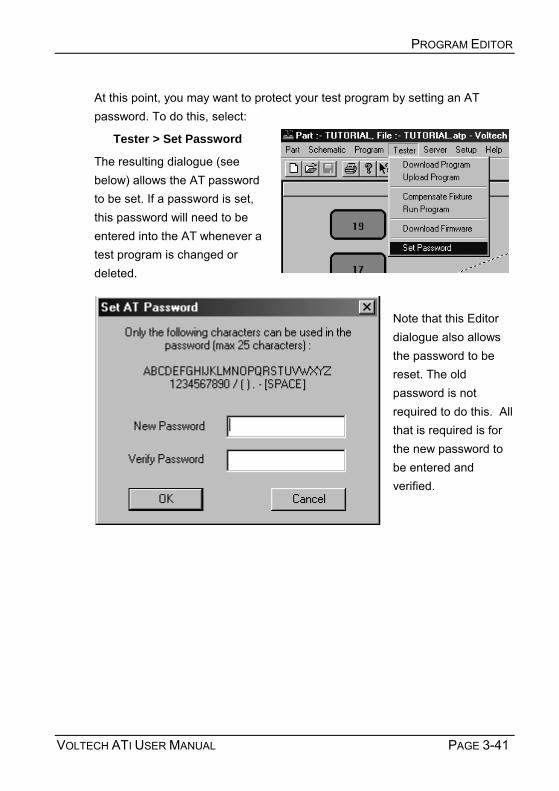
PROGRAM EDITOR
VOLTECH ATI USER MANUAL PAGE 3-41
At this point, you may want to protect your test program by setting an AT password. To do this, select:
Tester > Set Password
The resulting dialogue (see below) allows the AT password to be set. If a password is set, this password will need to be entered into the AT whenever a test program is changed or deleted.
Note that this Editor dialogue also allows the password to be reset. The old password is not required to do this. All that is required is for the new password to be entered and verified.

PROGRAM EDITOR
PAGE 3-42 VOLTECH ATI USER MANUAL
3.5 ERROR CODES Voltech AT Series testers provide the operator with two types of error detection:
• An electrically sound hardware integrity test, called self-test, with the provision of error codes, should an electrical fault be detected.
• Return of an error code during transformer testing to assist in diagnosing whether incorrect test parameters have been used or poor connections have caused the fault.
During normal component or transformer testing and/or while running self-test, voltage and current signals are constantly being generated, stabilized, measured and dissipated. Should a problem occur during one of these four stages, a unique error code is produced and displayed by the AT Series tester. The error code consists of a DSP (digital signal processor) status error code and a reason for DSP status error code.
The DSP status error code is a four-digit number that indicates that something has gone wrong. Each error code translates into an effect (a short description of the fault), such as a current or voltage overload, that can help the operator diagnose the cause of the problem. The DSP status error code is seen on self-test failures and on the Editors results screen.
The reason for DSP status error code is a one or two-digit number, displayed in parentheses, that explains the reason for the four-digit DSP status error code. These reason for DSP status error code translates into why a status error was displayed. This, again, can help the operator diagnose the cause of the problem. The reason for DSP status error code is only seen on self-test failures.
For the operator, the DSP status error codes can assist in determining if the fault is due to a poor fixture or an incorrectly seated part, or it could prompt an investigation into the appropriate test parameters being used. For the more serious faults, the user can contact their local Voltech technical support group and by explaining the application along with the DSP status error code can speed up and help the technical support engineer investigate the cause of the fault.

PROGRAM EDITOR
VOLTECH ATI USER MANUAL PAGE 3-43
3.5.1 FRONT-PANEL ERROR CODES When a fault is detected, the first DSP error code seen is a four-digit hexadecimal number, called the DSP status error code; the second is a one or a two-digit hexadecimal number in parentheses, called the reason for DSP status error code. This one or two digit code is only displayed with self-test failures.
Status error codes can be seen after a self-test failure. To view the error code, at the FAIL display, press the Details softkey. The following display will show the two status error codes: the first four digits being the DSP status error code and the second single or two-digit number in parentheses being the reason for DSP status error code.
Important Note:
Should self-test fail for any reason, contact Voltech technical support immediately, providing the following information:
• Serial number of the instrument
• Status error codes (the four-digit number and the one or two-digit number in parentheses on the display)
3.5.2 EDITOR ERROR CODES Status error codes are also shown when using the Editor software in download and run mode. They are shown at the end of each test result. Only the first four-digit error code is displayed when using the Editor.

PROGRAM EDITOR
PAGE 3-44 VOLTECH ATI USER MANUAL
If you look at the test results screen shown above, you will see that test 4 (LBAL) contains a status error code of 0010. This error code indicates that The measurement had not settled in time. Although this test passed, it indicates that a problem existed during the test sequence. In this particular example, the fault was due to a poor connection to the core of the transformer.
The following table gives the error codes that can appear when using the run facility in the Editor or when viewing on-line results with the Server. These error codes can give specific help in modifying the test program, depending on the tests used.
The error code is a 16-bit binary code, which is shown in hexadecimal notation in the table below. The error codes indicate one single bit of the 16-bit code, and therefore one or more errors could occur at the same time, which will be shown as a full, 4-digit hexadecimal code. For example, if a voltage over-range

PROGRAM EDITOR
VOLTECH ATI USER MANUAL PAGE 3-45
(xxx1) and a current over-range (xxx2) have occurred at the same time during test, then the error code is *0003* (i.e., both bits 0 and 1 set in the 16 bit binary error code).
If a test has failed due to an interrupt, then an additional code is attached to bits 12-15 of the error code as the table details further.
Hex Code
Error
0000 Test passed with no errors.
xxx1 Voltage over-range occurred.
xxx2 Current over-range occurred.
xxx4 Ramp-up process has been aborted; too much load.
xx2x The test parameters could not be trimmed to required value;
incorrect test parameters for the load.
xx4x An error occurred after ramp-down; current did not decay away in
time.
x1xx Current limit fail (hi-pot tests only); test current exceeded pre-
programmed limit (AT3600 only).
x2xx Voltage present (Vpres) did not go away in time; something on the
fixture is staying charged (AT3600 only).
#4xx The test has failed due to an interrupt (see table below).
Where # = reason for interrupt fail.
1 The safety interlock interrupt has terminated the test; a break has
occurred from the safety interlock port (AT3600 only).
3 A hi-pot trip interrupt has terminated the test; a flashover has
occurred or the current has exceeded the ATs current capabilities
(can occur on HPAC, HPDC and IR) (AT3600 only).
4 A STOP interrupt has terminated the test from the STOP flag of the
remote port.
5 An 8kV interrupt has terminated the test - voltage > 8kV (AT3600
only).
7 An over-temperature interrupt has terminated the test; unit has
become too hot (AT3600 only).
8 An auxiliary trip interrupt has terminated the test; this can be
created by an attached device to the peripherals port.

PROGRAM EDITOR
PAGE 3-46 VOLTECH ATI USER MANUAL
3.6 FIXTURE COMPENSATION (SEE ALSO SECTION 2.8)
Often when measuring small values of resistance, inductance or capacitance, the effects of the fixture can add significant errors to the results. To allow you to make more accurate measurements, the AT Series Testers have built-in firmware to compensate for the fixture parasitics.
If fixture compensation is required, follow steps 1, 2 and 4 of the procedure in described earlier in this chapter, so that the tester is connected and the program is downloaded.
Then from the top-level menu bar, select:
Tester > Compensate Fixture
Most programs will contain at least one test where fixture compensation can be applied. In this case, you will then see one or two messages:
At this point you should ensure that the appropriate fixture has been placed on the tester and a short-circuit bobbin fitted. For the following open-circuit compensation, remember to remove the short-circuit bobbin.
After you have clicked on the OK button at either of the messages, the tester will be commanded to make the compensation measurements for your test program.

PROGRAM EDITOR
VOLTECH ATI USER MANUAL PAGE 3-47
If errors are encountered, such as a shorting link is not fitted, the editor will display the appropriate warning message, and allow you either to try again, or to cancel the compensation.
When the compensation measurements have been successfully completed, the compensation values for each test in the program will be stored inside the tester. Any subsequent measurements (started as described above by clicking on Tester - Run Program) will return compensated results to the Editor.
If you are not sure whether to compensate or not, simply try it. If any of the results change significantly, then it should be done.
REMEMBER: Whenever you make changes to the program, the compensation results in the tester will no longer be valid. Make sure to compensate again each time you download a test program to an AT Series Tester, whether the program has changed or not.

PROGRAM EDITOR
PAGE 3-48 VOLTECH ATI USER MANUAL
3.7 PROGRAMMING HINTS AND TIPS
The following is a list of points that should be remembered when you are creating your test programs.
1. Create your schematic first.
When you are creating your test programs, you should work in the following order:
a. Initially, create the schematic.
b. Then, set up the program options.
c. Finally, create the list of tests that make up the program. Note: If you make any changes to the schematic after you have created the list of tests, then some tests may be inadvertently deleted. Examples where this may happen are: deleting a winding or a terminal, and renaming a terminal.
2. Use the recommended order for the tests in the program.
The actual tests used in the program are, of course, dependent upon the type of transformer to be tested, and the number of parameters you have chosen to test.
However, it is recommended that you generally do the tests in the following order:
a. Continuity
To detect a transformer not correctly plugged into the test fixture, and any open circuit windings.
b. Primary inductance
To detect faulty core material, and the wrong number of primary turns.
c. Turns ratios
To detect any windings with the wrong number of turns.
i

PROGRAM EDITOR
VOLTECH ATI USER MANUAL PAGE 3-49
d. Insulation resistance
To detect poor interwinding isolation where safety is not an issue, for example between two secondary windings.
e. Safety tests such as hi-pot
Available only on the Voltech AT3600, Hi-Pot must be used to detect poor interwinding isolation where safety is an issue. For example, from a primary winding to a secondary winding on a mains isolation transformer.
For iron cored transformers operating at the 50 or 60Hz line frequency, where normal operation extends to the point of core saturation, magnetizing current and open circuit voltage measurement are normally the preferred tests. These tests are available only on the Voltech AT3600.
3. Use test limits that are as wide as possible. For example, if you are testing the turns ratio between windings where the actual number of turns on one of the windings is only 10, specify limits of ± 5% (which is equivalent to half a turn).
4. Make use of the Measure button. For many tests, the dialogue box for the test contains a button labeled Measure.
If, when you are creating your test program, you have a tester connected to your PC, fitted with the appropriate test fixture containing a specimen transformer, clicking on the Measure button will signal the tester to measure the actual parameter of the test. The result will be returned to the PC, and the Editor will insert it as the nominal value in the limits section of the test dialogue box.
This is often the best way to find the value for some of the parameters which you may wish to test, but which do not appear on the actual transformer design documents.
5. Finally, download and run the program from the Editor and make sure the results are what you expect before you use it in production.

PROGRAM EDITOR
PAGE 3-50 VOLTECH ATI USER MANUAL

VOLTECH ATI USER MANUAL PAGE 4-1
4 AT SERIES SERVER

AT SERIES SERVER
PAGE 4-2 VOLTECH ATI USER MANUAL

AT SERIES SERVER
VOLTECH ATI USER MANUAL PAGE 4-3
Contents – AT Series Server 4.1. INTRODUCTION.........................................................................................4-5 4.2. TEST PROGRAM HANDLING ......................................................................4-6
4.2.1. Storing Test Programs ................................................................................ 4-6 4.2.2. Viewing a Test Program.............................................................................. 4-7 4.2.3. Saving a New Copy of a Part ...................................................................... 4-8 4.2.4. Deleting a Test Program ............................................................................. 4-9 4.2.5. Grouping Test Programs ........................................................................... 4-10
4.3. TEST RESULTS HANDLING......................................................................4-11 4.3.1. Receiving Test Results.............................................................................. 4-11 4.3.2. Result Display and Analysis ...................................................................... 4-13 4.3.3. Simple On-line Monitoring ......................................................................... 4-13 4.3.4. Batch Statistics On-line Analysis............................................................... 4-14 4.3.5. On-line Analysis via a Database ............................................................... 4-17 4.3.6. Database Tables ....................................................................................... 4-24 4.3.7. On-line Analysis via OLE........................................................................... 4-35 4.3.8. Additional Notes for the Above Example ................................................... 4-43 4.3.9. Off-line Analysis ........................................................................................ 4-45
4.4. LICENSE REGISTRATION.........................................................................4-50 4.4.1. Enabling the Licensed Features................................................................ 4-50 4.4.2. Transferring the License to Another PC .................................................... 4-52

AT SERIES SERVER
PAGE 4-4 VOLTECH ATI USER MANUAL

AT SERIES SERVER
VOLTECH ATI USER MANUAL PAGE 4-5
4.1 INTRODUCTION
The Server program supplied with your AT Series Tester may be considered as an on-line storage system.
The server will handle two types of data:
• TEST PROGRAMS
• TEST RESULTS
Test programs that are created using the Editor application may be uploaded into the Server central file store. All testers connected to the Server then have access to the central store. Programs are called up from the Server, sent to and then executed within the tester.
The features of the Server include:
• MS Windows application style dialogues and tools.
• Storage of all previously created test programs.
• Transfer of test programs to the tester on request.
• Viewing of test programs outside the test program Editor environment.
• Test results may be received and stored in a database-ready format for easy off -line analysis.
• OLE 2 support allowing real-time analysis of your production test system.
Test programs may be stored on floppy disk for back-up or inter-site transfer.
Installation and set-up of the Server program is explained in chapter 2.

AT SERIES SERVER
PAGE 4-6 VOLTECH ATI USER MANUAL
4.2 TEST PROGRAM HANDLING
4.2.1 STORING TEST PROGRAMS After a test program has been created using the Editor application, it will be ready for use with your AT Series Tester. The diagram below shows a potential connection scheme for use with a single tester and two PCs.
Before program requests or uploads may be completed, the tester must be configured for Server mode. See chapter 2.
You may copy program files directly into the program directory used by the server application.
IMPORTANT: When a program file is copied to the Server and a file with the same name is already resident within the Server, the incoming file will replace the previous file.
i
Network connection or both
installed on the same local PC
Server
Editor
ATi

AT SERIES SERVER
VOLTECH ATI USER MANUAL PAGE 4-7
4.2.2 VIEWING A TEST PROGRAM Each test program has a part name. To view a particular test program you will need to know its part name. Select FILE, PART and then OPEN from the menu bar. You may select the part to open from the list displayed, or change the path and drive to search for other parts.
When you have selected the correct part to open, click on the OK button.
You will now be able to view the text listing of the test program chosen.

AT SERIES SERVER
PAGE 4-8 VOLTECH ATI USER MANUAL
4.2.3 SAVING A NEW COPY OF A PART Using the SAVE AS function under the PART menu, you are able to save a new copy of the same test program under a new part name.
• Open the part required and select SAVE AS.
• Enter the new part name and select the appropriate file path.
• Click on the OK button.
A new copy of the test program will now be saved with the new part name as specified.
IMPORTANT: When using the SAVE AS function you must be aware that it is not a 'RENAME' function. The previous copy of the test program with the original part name will remain in your program directory.
Note that if you are attempting to save a new part under the same name as an already existing part, a message box will appear asking you if you want to replace the existing part. If a Server password has been set, you will have to enter the correct authorization password in the Save As authorization dialog box (see below).
i

AT SERIES SERVER
VOLTECH ATI USER MANUAL PAGE 4-9
4.2.4 DELETING A TEST PROGRAM If you need to remove a part from the Server program directory, a button has been provided within the PART, OPEN dialogue.
Select the part to be deleted and press the DELETE button.
You will then be prompted to enter the password (as defined when installing the Server software) to allow the part to be deleted.
The program will then be removed from the Server directory.
IMPORTANT: Once a part has been deleted it may not be recovered. Before deleting a part it is advisable to open and view to ensure you are deleting the correct test program.
i

AT SERIES SERVER
PAGE 4-10 VOLTECH ATI USER MANUAL
4.2.5 GROUPING TEST PROGRAMS Programs that are used on the transformer tester at similar times may be grouped for convenience. For example, a number of transformers all based on the same bobbin may be tested at the same time.
When a program group has been defined it may be downloaded to the tester. Each of the parts within the group will then be available for local use. The parts will be stored in non-volatile RAM. No programs are lost after power-down.
The following dialogue is used to configure groups and may be located under the Setup menu in the Server:
Double-clicking on any part in the left hand list will add it to the right hand, grouped list.
When you have completed editing a group you will see it added to the available group list. To transfer the group to the tester it must be requested by the tester. See Chapter 2 of the manual for details.
IMPORTANT: The group function does not store a new copy of each part when a group is defined. Only reference is made to the part being in a group. DO NOT delete a part after including it in a group other wise the part will be lost, and the group rendered invalid.
i

AT SERIES SERVER
VOLTECH ATI USER MANUAL PAGE 4-11
4.3 TEST RESULTS HANDLING 4.3.1 RECEIVING TEST RESULTS By default, the AT Series Tester does not automatically send test results back to the Server. Results will only be sent back for test programs that have been set up with the Send Results to Server option enabled.
The Server receives test results from the tester via the same serial connection used for transferring test programs to the tester. Results handling is a separate function of the Server program, and is not part of program transfer. Where more than one tester is connected to your server PC, the one Server program handles all the transformer tester results as well as acting as the central Server.
All results sent by one tester's channel during one day, are collected together and formed into one large file. This file is known as the batch results file.
One batch results file will be generated per open channel, per day. Batch files are stored under the specified results directory; see chapter 2, section 2.2.6.
The DOS filename of the batch results file is generated as follows:
c<n><dd><mm><yy>.atr
Where:
n channel number
dd day number
mm month number
yy year number
example:
c1250297.atr (Channel 1, 25-02-1997)
atr is the reserved file extension used by the Server to indicate a stored test result file.
What follows is an example of the first part of a batch result file, as viewed in a standard text editor.
Note the DOS file name (c6200697.atr) and the part name (TUTORIAL) are both listed within the file.

AT SERIES SERVER
PAGE 4-12 VOLTECH ATI USER MANUAL
"VOLTECH ATi RESULTS FILE" "Server Program Version: 2.37” "Communication Channel: 6" "ATi ID: 0571" "ATi Software Version: 2.46" "File name: C6200500.atr" "Test Date: 20 May 2000" "Part #","Tutorial" "Fixture ID","Universal" "Operator" "Batch #" "No Fixture Compensation" "Result #","Serial #","Time","Pass/Fail","","001 R","","","","002 "","","","","","Minimum","Maximum","Reading","","Minimum","Maximum","R 1,"","10:44:20","Pass","",59,73,6.776850E+01,"Pass",3,,3.223899E+00,"P 2,"","10:44:23","Pass","",59,73,6.776832E+01,"Pass",3,,3.110549E+00,"P 3,"","10:44:24","Pass","",59,73,6.776363E+01,"Pass",3,,3.125640E+00,"P 4,"","10:44:26","Pass","",59,73,6.777967E+01,"Pass",3,,3.135034E+00,"P 5,"","10:44:27","Pass","",59,73,6.777842E+01,"Pass",3,,3.185198E+00,"P 6,"","10:44:29","Pass","",59,73,6.778374E+01,"Pass",3,,3.152627E+00,"P
And so forth, for each result, until a change of batch or part. If a result window is closed, the connection to the transformer tester will be lost. A warning is issued before connections are removed.

AT SERIES SERVER
VOLTECH ATI USER MANUAL PAGE 4-13
4.3.2 RESULT DISPLAY AND ANALYSIS Three approaches have been provided to allow observation of your test result data:
• Simple on-line monitoring
• Batch statistics on-line analysis
• On-Line analysis
• Off-Line analysis
4.3.3 SIMPLE ON-LINE MONITORING Each time a COM to AT Series Tester connection is opened using the Setup > Communication menu, an accompanying result monitoring window will be created.
One result-monitoring window will be present for each open channel.
When results are sent from the tester they will be displayed in the monitoring window before passing to the batch result file. The most recent result for each channel will be visible in the window.
An open result window may be minimised at any time and subsequently maximized using the icons indicated.
Minimize Maximize

AT SERIES SERVER
PAGE 4-14 VOLTECH ATI USER MANUAL
4.3.4 BATCH STATISTICS ON-LINE ANALYSIS Setting Up Batch Statistics
From the 'Set-up' menu, select 'Results' to see the following dialogue:
Select 'Display Basic Statistics' to save results to a database. For this feature to operate a licence for use must first be obtained from your Voltech supplier.
All results formats can be saved simultaneously.
Basic statistics displays, on-line, a summary of the results for the current batch of transformers that is being tested on every AT connected to the Server. Results for previous batches can also be opened and the statistics displayed and printed.

AT SERIES SERVER
VOLTECH ATI USER MANUAL PAGE 4-15
The batch statistics window display is automatically shown once this feature is enabled. For each AT connected to the Server the following information is displayed:
• The type of AT and its serial number, and the part name, operator and batch.
• PASS or FAIL for the last part tested, the total tested so far and the serial number of the last part tested.
• The number that have passed and failed, and the AQL<+> (Acceptable Quality Level) of the transformer.
• The number of re-tries that have been attempted, the percentage of failures so far and the number of transformers that failed out of the last 10 tested.
• For each test in the program, the test limits, the last result and the accumulated number of fails for each test.
Results may also be exported or printed using the normal options found under the file menu.
AQL
AQL (Acceptable Quality Level) settings for production test are defined for each program using the Editor. AQL is the level of test failures in a batch that are acceptable. Exceeding the AQL is an indication that there is problem with

AT SERIES SERVER
PAGE 4-16 VOLTECH ATI USER MANUAL
the quality of the production process or the quality of materials used. AQL monitoring is an optional feature of the Voltech PC Server which displays live summary results from multiple AT testers. When the AQL level set here is reached or exceeded, the Server will display a warning.
'AQL No. of Parts' is the number of failures in the batch at which a warning will be displayed on the Server. This is most often used when the batch size is always similar, or zero / very small numbers of defects are expected.
'AQL % of Parts' is the percentage level of failures at which a warning will be displayed on the Server. Note that this AQL is only applied after sufficient parts have been tested to make the percentage meaningful. When setting AQL % of Parts to be 1% for example, a warning will only be displayed after 100/1 = 100 parts have been tested.
Both types of limit may be used at the same time. Reaching any one limit will cause a warning to be displayed on the Server.
When an AQL level is reached or exceeded the Server will display a warning:
Click on 'OK' to acknowledge the warning. You will be given the option to disable the warning for further parts in the batch. Normally, you would select 'No' to leave the AQL checking active for the rest of the batch. When a new batch is started, the AQL level is reset according to the level entered for the part using the Voltech AT Editor.

AT SERIES SERVER
VOLTECH ATI USER MANUAL PAGE 4-17
4.3.5 ON-LINE ANALYSIS VIA A DATABASE The AT Server software can store test results in an electronic database. This provides a very powerful and versatile method of recording and analysing test results historically or on-line. The Server uses standard Windows methods (including OLE DB and ODBC) to connect to a variety of databases that conform to these specifications.
Once stored in a database the data may then be analysed using tools available in the database application or tools provided by specialist software packages such as those available for SPC (Statistical Process Control). One example of this is to monitor in real time the trend in a winding resistance to identify a defective drum of copper. You would then be able to rectify the fault during production rather than producing a large stock of QA failed transformers all wound with the defective wire.
Setting Up Database Results Storage
From the 'Set-up' menu, select 'Results' to see the following dialogue:
Select 'Database Results Saving' to save results to a database. For this feature to operate properly a connection to the database must be set up first and a licence for use must be obtained from your Voltech supplier.
All results formats can be saved simultaneously.

AT SERIES SERVER
PAGE 4-18 VOLTECH ATI USER MANUAL
Click on 'Advanced' to set up your database connection:
To connect to your database, the Server software uses a connection string that contains (amongst other things) the name of a provider, the name and location of the database and a valid database user name and password (if required). You may need to consult with the database or network administrator to obtain this information.
If a connection has already been established you will see the connection string in the window inside this dialogue. If you wish to remove an existing connection string, click on 'Clear Connection'.

AT SERIES SERVER
VOLTECH ATI USER MANUAL PAGE 4-19
To establish a new connection click on 'Connection Type'.
The 'Data Link Properties' dialogue is a standard one that is supplied by Windows. You should choose the provider that will provide the connection to the type of database that you are using.
Several different types of provider are installed along with the Server software; others may be available if you have a database application installed on the same PC as the Server. If the provider you need is not available and the database is installed on another PC, ask the database administrator for the database client tools for the Server PC.

AT SERIES SERVER
PAGE 4-20 VOLTECH ATI USER MANUAL
Typical provider types are:
Database Provider
Microsoft Access 97 Microsoft Jet 3.51
Microsoft Access 2000 Microsoft Jet 4.0
Oracle Microsoft OLE DB Provider for Oracle
SQL Server Microsoft OLE DB Provider for SQL Server
In addition it is possible to connect to ODBC compliant databases (including Microsoft Access) using the Microsoft OLE DB Provider for ODBC Drivers.
Click on 'Next' when you have chosen the correct provider.
Select the database name that you will be using by clicking on 'Select'. If you wish to create a new database for AT Server results, do so now using your database program.
The default user name 'Admin' with no password may be adequate. Consult your database administrator if you need a specific user name and password.

AT SERIES SERVER
VOLTECH ATI USER MANUAL PAGE 4-21
When you click on 'Test Connection' you should see something similar to:
Next, click on 'OK' of the 'Test connection succeeded' dialogue and select the 'Advanced' tab.

AT SERIES SERVER
PAGE 4-22 VOLTECH ATI USER MANUAL
Check that the 'Access permissions' for the database are as required. 'Share Deny None' is the default and is usually the most suitable setting.
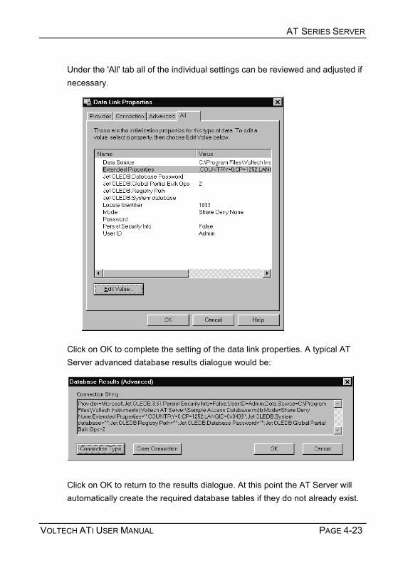
AT SERIES SERVER
VOLTECH ATI USER MANUAL PAGE 4-23
Under the 'All' tab all of the individual settings can be reviewed and adjusted if necessary.
Click on OK to complete the setting of the data link properties. A typical AT Server advanced database results dialogue would be:
Click on OK to return to the results dialogue. At this point the AT Server will automatically create the required database tables if they do not already exist.

AT SERIES SERVER
PAGE 4-24 VOLTECH ATI USER MANUAL
Ensure that 'Database Results Saving' is checked and click on 'OK'. Whenever a results window is open, the results will now be stored in the selected database.
4.3.6 DATABASE TABLES The server software automatically creates the following tables in the selected database (if they do not already exist) and stores data within the tables using the structure defined here.
The tables store all the information that is available concerning the results (including time, date, limits, operator etc.) in a very compact and efficient structure.
Note that new data is not necessarily appended to the end of a table; it may appear anywhere within.
Table: tblVoltechATUnitID Field Format Notes ATUnitID Text (25) Index ID UnitType Text (10) AT3600, AT1600, ATi UnitID Text (10) Unit Serial Number FirmwareID Text (10) Unit Firmware Version

AT SERIES SERVER
VOLTECH ATI USER MANUAL PAGE 4-25
Table: tblVoltechResults Field Format Notes ResultID Text (25) Index ID RunID Text (25) As tblVoltechRunID.RunID TestID Text (25) As tblVoltechTestID.TestID TestNo Number (Long Integer) Test number as in test
program OC_Comp Text (5) YES , NO , N/AOpen
Circuit Compensation status SC_Comp Text (5) YES , NO , N/AShort
Circuit Compensation status Load_Comp Text (5) YES , NO , N/ALoad
Compensation (future development)
Result Number (Single) Actual test result TestStatus Text (5) DSP Status for test PassFail Text (5) PASS/FAIL Individual test
pass or fail result Table: tblVoltechRunID Field Format Notes RunID Text (25) Index ID Date Date/Time (Short Date) Date of Test Run Time Date/Time (Long Time) Time of Test Run ATUnitID Text (25) As
tblVoltechATUnitID.ATUnitID
PartID Text (25) Part name FixtureID Text (25) Fixture name OperatorID Text (25) Operator name BatchID Text (25) Batch name TransformerSerialNo Text (25) Transformer serial number OverallResult Text (10) PASS/FAIL/RE-
RUN/ABORTOverall test pass or fail result and Re-Run result.

AT SERIES SERVER
PAGE 4-26 VOLTECH ATI USER MANUAL
Table: tblVoltechTestID Field Format Notes TestID Text (25) Index ID TestMnemonic Text (10) Individual test mnemonic TestUnits Text (10) Individual test units CheckType Text (5) NONE/MIN/MAX/DIFF/POLType
of test limits (see *) MinLimit Number (Single) Minimum limit for test (see *) MaxLimit Number (Single) Maximum limit for test (see *)
* Notes:
(CheckType = NONE) If there are no Min or Max limits, MinLimit = 0 and MaxLimit = 0
(CheckType = MIN) If there is a Min limit only, MaxLimit = 0
(CheckType = MAX) If there is a Max limit only, MinLimit = 0
(CheckType = DIFF) If there is a Min and Max limit
(CheckType = POL) Polarity test
If Positive Polarity test, MinLimit = 0 and MaxLimit = 1
If Negative Polarity test, MinLimit = -1 and MaxLimit = 0

AT SERIES SERVER
VOLTECH ATI USER MANUAL PAGE 4-27
Charting and Analysis Using SPC/SQC Software
Once an AT Server to database connection has been made, it is possible to connect third party analysis software to the same database for live on-line (or offline) data analysis. The example reports presented here were created using PQ Systems ChartRunner, but many other charting and analysis programs are available. Voltech does not recommend one package more than any other. You should choose to use the one that best meets your needs.
Inductance Trend Analysis

AT SERIES SERVER
PAGE 4-28 VOLTECH ATI USER MANUAL
Resistance Distribution Analysis
Overall Pass / Fail Analysis
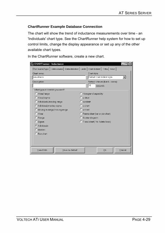
AT SERIES SERVER
VOLTECH ATI USER MANUAL PAGE 4-29
ChartRunner Example Database Connection
The chart will show the trend of inductance measurements over time - an 'Individuals' chart type. See the ChartRunner help system for how to set up control limits, change the display appearance or set up any of the other available chart types.
In the ChartRunner software, create a new chart.

AT SERIES SERVER
PAGE 4-30 VOLTECH ATI USER MANUAL
Enter a chart type, the refresh rate (for on-line analysis) and the chart type.
Click on the 'Data Source' tab to choose the results database:
Under the 'Data Definition' tab:
Select the table of the database that holds the data that you want to chart. (You may also select a query that has been written in the database or write a 'Custom Query').

AT SERIES SERVER
VOLTECH ATI USER MANUAL PAGE 4-31
In this case the database table 'tblVoltechresults' has been chosen and the column 'Result' flagged as a measurement. (To do this, click on the 'Treat as' column of the 'Result' row and select 'Measurement' from the drop down list).
Next, click on 'Filtering' and filter the data for 'TestNo' = 2.
This selects only the results for test number 2 of the AT test program (which is an inductance test).

AT SERIES SERVER
PAGE 4-32 VOLTECH ATI USER MANUAL
Next click on the 'Limits' tab and enter appropriate specification limits that will appear on the chart. The ChartRunner software can automatically select appropriate control limits from the data. This is the default and recommended setting.

AT SERIES SERVER
VOLTECH ATI USER MANUAL PAGE 4-33
Under the 'Control Chart' tab, display options (including axis scaling) can be altered.
Other options including chart titles and size can be altered by selecting the 'Titles' and 'Misc.' tabs.
Click on 'OK' when finished. Double click on the chart definition to display the chart.
Please refer to the help system of the analysis software you are using for further advice and information on chart types, connectivity, options and statistical analysis in general.

AT SERIES SERVER
PAGE 4-34 VOLTECH ATI USER MANUAL
Free trial versions of ChartRunner are available from PQSystems at www.pqsystems.com or any of their regional offices.
United States
PQ Systems Inc. Corporate Headquarters
Toll free: 1-800-777-3020
Phone: 937-885-2255
E-mail: [email protected]
Europe
PQ Systems Europe Ltd.
Phone: +44 1704 871465
E-mail: [email protected]
Asia-Pacific
PQ Systems Pty. Ltd.
Tel. (Australia) 03-9770-1960
E-mail: [email protected]

AT SERIES SERVER
VOLTECH ATI USER MANUAL PAGE 4-35
4.3.7 ON-LINE ANALYSIS VIA OLE The MS Windows environment provides a system of transferring data between active applications in real-time known as Object Link Embedding (OLE). OLE2 is the latest version of the transfer standard and is fully supported by the Server application.
Embedded data links allow test results received by the server to automatically pass into a second application, which may be your own custom software or a spreadsheet such as Microsoft Excel. Server OLE commands also allow you to load and execute test programs. OLE is the analysis and control method preferred by users who wish to operate the AT under software control.
OLE is already configured ready-to-go within the Server application. Your client application will need to be setup to request data from the Server. Refer to your own application handbook for details of OLE setup.
IMPORTANT: Attempting to make more than ten data requests per second may result in data loss or corruption.
NOTES:
The automation object is called Server.Results
The exposed OLE automation methods are:
GetVariantResult (LPCSTR ComPort, short TestNumber)
Where: LPCSTR ComPort is a pointer to a string ComPort
ComPort = COM2... COM9
= the port connected to the AT Series
Tester that gives the required result
TestNumber = Integer number for test within program
!

AT SERIES SERVER
PAGE 4-36 VOLTECH ATI USER MANUAL
The number returned is a float representing the value of the result measured or a zero if no result was available.
This call returns a result on success or a failure string:
INVALID COM PORT” no valid COM port found
“COM PORT IS NOT OPEN” COM port requested not connected to an AT Series Tester
“INVALID RESULT NUMBER” the requested result number is out of range
“NO RESULT” no updated result data available
Further Voltech Server OLE functions are described below. They use the same format and failure strings as 'GetVariant Result'. Only function specific responses and return values are shown.
NewDataAvailable (LPCSTR ComPort)
Returns TRUE or FALSE (Boolean 1 or 0 as variant) depending on whether new data is available. If this function returns true it means that new data can be read back via the OLE. If false then no new data has come in since the last read
GetPartID (LPCSTR ComPort)
Returns the part name on success or a failure string:
NO PART ID no valid part name found
GetFixtureID (LPCSTR ComPort)
This call returns the fixture name on success or a failure string:
NO FIXTURE ID no valid fixture name found
GetOperatorID (LPCSTR ComPort)
This call returns the operator name on success or a failure string:
NO OPERATOR ID no valid operator name found
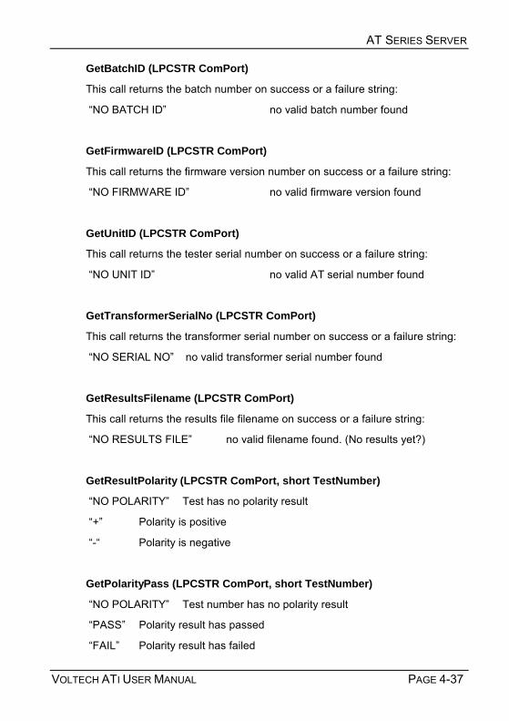
AT SERIES SERVER
VOLTECH ATI USER MANUAL PAGE 4-37
GetBatchID (LPCSTR ComPort)
This call returns the batch number on success or a failure string:
NO BATCH ID no valid batch number found
GetFirmwareID (LPCSTR ComPort)
This call returns the firmware version number on success or a failure string:
NO FIRMWARE ID no valid firmware version found
GetUnitID (LPCSTR ComPort)
This call returns the tester serial number on success or a failure string:
NO UNIT ID no valid AT serial number found
GetTransformerSerialNo (LPCSTR ComPort)
This call returns the transformer serial number on success or a failure string:
NO SERIAL NO no valid transformer serial number found
GetResultsFilename (LPCSTR ComPort)
This call returns the results file filename on success or a failure string:
NO RESULTS FILE no valid filename found. (No results yet?)
GetResultPolarity (LPCSTR ComPort, short TestNumber)
NO POLARITY Test has no polarity result
+ Polarity is positive
- Polarity is negative
GetPolarityPass (LPCSTR ComPort, short TestNumber)
NO POLARITY Test number has no polarity result
PASS Polarity result has passed
FAIL Polarity result has failed

AT SERIES SERVER
PAGE 4-38 VOLTECH ATI USER MANUAL
GetTestPass (LPCSTR ComPort, short TestNumber)
PASS Test result has passed
FAIL Test result has failed
GetOverallPass (LPCSTR ComPort)
PASS All tests have passed
FAIL One or more tests have failed
GetNumberOfTests (LPCSTR ComPort)
Returns a short integer variant type giving the number of tests in the program. Use for possible determination of the maximum value for TestNumber in other functions.
GetMinLimit (LPCSTR ComPort, short TestNumber)
Float value giving the minimum limit for the test TestNumber.
NO LIMIT This test has no minimum limit.
GetMaxLimit (LPCSTR ComPort, short TestNumber)
Float value giving the maximum limit for the test TestNumber.
NO LIMIT This test has no maximum limit.
GetTestStatus (LPCSTR ComPort, short TestNumber)
Returns four-digit hex string (####), giving the test status, as seen on Editor results screen.
GetTestMnemonic (LPCSTR ComPort, short TestNumber)
Returns the test mnemonic as a string, i.e. LBAL.

AT SERIES SERVER
VOLTECH ATI USER MANUAL PAGE 4-39
GetTestUnits (LPCSTR ComPort, short TestNumber)
Returns the test units as a string, i.e. Ohm.
GetCompensationStatus (LPCSTR ComPort)
NO COMPENSATION STATUS No status received yet.
No Fixture Compensation Program has not been compensated.
Fixture Compensation: successful Compensation all OK.
Fixture Compensation: fail + ExtraString Compensation has failed.
GetUnitType(LPCSTR ComPort)
Returns AT3600, AT1600 or ATi depending on the type of instrument connected to the ComPort.
GetResult (LPCSTR ComPort, short TestNumber)
The number returned is a float representing the value of the result measured or a zero if no result was available.
This function is included for compatibility with older versions of the Voltech AT Server. It is not recommended for new applications.

AT SERIES SERVER
PAGE 4-40 VOLTECH ATI USER MANUAL
This section shows available functions for controlling an attached instrument via the server. This is to allow basic instrument control in applications where the AT is being used entirely remotely. The functions available allow a program to be loaded into an AT, and give the ability to run and stop it.
Variant LoadProgramToAT (LPCSTR ComPort, LPCSTR ProgName)
PROGRAM DOES NOT EXIST Program is not in the Server's program folder.
INVALID PROGRAM Program fails AT test program validation.
LOADING Returned when command is first sent to server, and every subsequent time it is sent until loading finishes.
"LOADED" The program has been successfully loaded, this will continue to be returned, and the program will not load until either StopAT() is called or the server receives results on that COM port.
Variant RunProgramInAT (LPCSTR ComPort)
NO PROGRAM The AT has no program to run.
"SENT" Returned when the program has started to run and every subsequent time the function is called until the server receives results.
DONE The program has finished running, results will be available. If the function is called after it has returned this value it will cause the program to be run again.
Variant StopAT (LPCSTR ComPort)
STOPPED The AT must stop whatever test it is running

AT SERIES SERVER
VOLTECH ATI USER MANUAL PAGE 4-41
Example of On-line Analysis
This section contains a simple example to illustrate how you may use OLE to transfer the measured results into a spreadsheet as they happen in real-time.
The spreadsheet used in the example is Microsoft Excel 97, and the module of code illustrated is written in the Visual Basic supplied with the spreadsheet.
Before attempting to create the spreadsheet, set up the AT and server:
• Use the editor to create a program containing 5 tests, where test number 3 measures a winding resistance.
• Ensure that the program option Send Results to Server is set to On.
• Transfer the program to the directory being used by the server for storing programs.
• Ensure that the server program is running, and that the COM Port to be used has been enabled.
• Connect the AT to the server PC, and use the PROGRAM - SET-UP menu to set the origin to SERVER.
• At the AT Top Level menu, press the EXECUTE softkey, and type in the name of the program.
• Run the program and check that the correct results are displayed in the on-line monitoring window.
Leave the Server program running, and on the same PC, start Microsoft Excel 97. A new (empty) spreadsheet will be created.
From the Excel top-level menu bar, select:
Tools > Macro > Macros
Enter the name OLE_Demo and then create.
Excel will then bring up a module sheet labelled Module 1. Type the following code into this module sheet:

AT SERIES SERVER
PAGE 4-42 VOLTECH ATI USER MANUAL
'************************************************************** 'OLE_Demo Sub ' 'Procedure to demonstrate linking AT results into an Excel spreadsheet 'in real time using OLE. ' 'The procedure will read the third test in the program and put the result 'into a cell on the third row of the spreadsheet. ' 'The procedure will do this for a total of 3 program runs, and then exit. Sub OLE_Demo() Dim objServerResult As Object Dim vntResult(1 To 99) As Variant Set objServerResult = CreateObject("Server.Results") nTest = 3 nNumRuns = 3 sComPort = "COM2" 'Dummy read to clear any previous result vntResult(nTest) = objServerResult.GetVariantResult(sComPort, nTest) MsgBox ("Press the RUN softkey on the AT") For nRun = 1 To nNumRuns 'Get the results Do vntResult(nTest) = objServerResult.GetVariantResult(sComPort, nTest) Loop Until (vntResult(nTest) <> "NO RESULT") And _ (vntResult(nTest) <> "INVALID RESULT NUMBER") Cells(3, 5 + nRun) = vntResult(nTest)'Put result in spreadsheet Next nRun MsgBox ("Done") End Sub

AT SERIES SERVER
VOLTECH ATI USER MANUAL PAGE 4-43
When you have finished typing the code, return to the Sheet 1 of the spreadsheet.
To run the code, again from the Excel top-level menu bar, select:
Tools > Macro
At the dialog box, select the name of the macro OLE_Demo, and click on the RUN button.
The code will now start to run, and after a few seconds, you will see the first message box defined in the code:
Click on the OK button. When you have pressed the RUN softkey and the first result has been read, the message box will disappear, and you will then see the first result entered into cell F3 of the spreadsheet.
Continue pressing the RUN softkey until the second message box is seen.
Click on the OK button to finish running the code.
4.3.8 ADDITIONAL NOTES FOR THE ABOVE EXAMPLE If there appear to be any problems while the code is running, press the escape key. This will halt the execution, and bring up a dialog box to allow you to either exit from the code execution, or to debug your code, for example by single-stepping through it.

AT SERIES SERVER
PAGE 4-44 VOLTECH ATI USER MANUAL
Once the results have been placed into cells in the spreadsheet, standard Excel functions may be used to perform further analysis on the data, or to present the data in different ways. As an example, you may wish to use the Excel Chart Wizard to produce a graph of the results. Alternatively, you may wish to add further code to the example shown above, as another way of extending the functionality. For guidance of what may be possible, please refer to the Microsoft Excel user manuals.
In the code example shown above, it is worth noting the following points:
vntResult(1 To 99) is declared as a variant type because the GetVariantResult method can return either a numerical value corresponding to a valid result, or a string corresponding to an error message.
The line
Set objServerResult = CreateObject("Server.Results") creates the server.Results automation object within Visual Basic. When trying to read the result with
Do vntResult(nTest) = objServerResult.GetVariantResult(sComPort, nTest) Loop Until (vntResult(nTest) <> "NO RESULT") And _ (vntResult(nTest) <> "INVALID RESULT NUMBER")
two tests for No Result and Invalid Result Number are included.
The GetVariant method will normally read back No Result, until a measurement has occurred. The next time it is executed after a new result has been sent to the server, GetVariant will read back the actual result value. The act of doing this will set a flag in the Server to say that the data has been read, so that any further executions of the GetVariant statement before another result has been transferred to the server will then return the No Result reply.
Although the test number is fixed (=3) in this example, the Invalid Result Number test is also included. This is because the GetVariant method can be

AT SERIES SERVER
VOLTECH ATI USER MANUAL PAGE 4-45
activated at exactly the same time as the results are being transferred from the AT to the server. Depending on the speed and other parameters of your PC, there may be a small time during the transfer when the result number requested can be read as invalid. Including this test in the loop will trap out this error.
Instead of using the GetVariantResult function itself to determine if new data is available, the NewDataAvailable function can be used. This function is recommended for use when more than one item of data is to be read after new data is available. For example, the NewDataAvailable function can be read in the do loop until it returns true, after which any other OLE function can be called to gather their return values knowing that all the data will be valid. Using the NewDataAvailable function also means that checking for 'INVALID RESULT NUMBER' and 'NO RESULT' return values is no longer necessary.
4.3.9 OFF-LINE ANALYSIS If you have no requirement for real-time analysis, but are interested in post-test analysis of test results, off-line data analysis should be adopted. An example of this would be to view the results file created the previous day.
As described in section one of this chapter, the batch result file is stored in a text based Comma Separated Variable format (CSV).
A spreadsheet is an ideal environment to analyze and manage your test data. Almost all spreadsheet applications are able to import a CSV file.
Once imported test results may be graphed, calculated, edited and printed like any other data. Using a package such as Microsoft Excel, macros may be setup to sort and extract the appropriate result sections, calculate and compile reports and finally produce a printout for records.
Refer to your own application handbook for details of importing and manipulating data.

AT SERIES SERVER
PAGE 4-46 VOLTECH ATI USER MANUAL
Example of Off-line Analysis
The spreadsheet used in the example is Microsoft Excel 97.
From the Excel top-level menu bar, select:
File > Open
Excel will then bring up the Open File dialogue box. Select the results file you wish to view and click on Open.
After clicking Open, the Text Import Wizard dialog box will appear:

AT SERIES SERVER
VOLTECH ATI USER MANUAL PAGE 4-47
Ensure that the De-limited option is checked and click on Next > to move to step two.
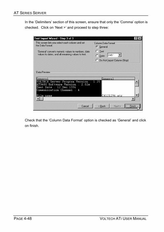
AT SERIES SERVER
PAGE 4-48 VOLTECH ATI USER MANUAL
In the Delimiters section of this screen, ensure that only the Comma option is checked. Click on Next > and proceed to step three:
Check that the Column Data Format option is checked as General and click on finish.

AT SERIES SERVER
VOLTECH ATI USER MANUAL PAGE 4-49
The results will now be displayed as shown below:
You may need to adjust the cell number format of the spreadsheet, and the width of the columns, in order to display the required number of decimal places.
Using functions built into the spreadsheet, the data obtained may now be used to create graphs and bar charts for a visual representation of your results. As an example, to produce a graph, select a group of results from one column; then click the Chart Wizard button and use this to create the graph you require in the normal way. For additional help on what may be possible, please refer to your spreadsheet user manuals.

AT SERIES SERVER
PAGE 4-50 VOLTECH ATI USER MANUAL
4.4 LICENSE REGISTRATION
4.4.1 ENABLING THE LICENSED FEATURES The Server software is supplied to you under the terms of our current license agreement and is for use on a single PC only. It is not necessary to register the software to use the program storage, CSV results storage or OLE features of the Server software.
The software must be registered however before you can use the database and basic batch statistics features.
The software may be registered in either trial (or 'demo') or full mode.
A FREE trial of the software may be obtained your Voltech supplier and will enable you to make full use of the database results storage feature for up to 30 days from registration. Please see below BEFORE requesting your trial code.

AT SERIES SERVER
VOLTECH ATI USER MANUAL PAGE 4-51
To register the software:
• Look at the registration details found under 'Registration' from the 'Help' menu. This dialogue will display an 'ID Code' that is unique to that PC installation.
• Contact your Voltech supplier with the exact 'ID Code' and you will be issued with a 'Key Code' provided that the appropriate payment has been received. (A 30-day trial key code may be supplied FREE OF CHARGE).
• Open the 'Registration' dialogue as above and enter the 'Key Code'. The software is now fully operational.
• The 'Key Code' is not time related and may be entered at any time after you have sent the 'ID Code' to Voltech.

AT SERIES SERVER
PAGE 4-52 VOLTECH ATI USER MANUAL
4.4.2 TRANSFERRING THE LICENSE TO ANOTHER PC If you wish to use the software on another PC you must transfer the license as described below BEFORE losing access to the existing installation.
To transfer the license:
• Install the software on the new destination PC.
• Take the ID code displayed in the new installation and enter it into the 'Transfer ID Code' section of the dialogue of the licensed software (as above) on the 'old' installation.
• Take the 'Transfer Key Code' that will be displayed in the dialogue above of the 'old' installation and enter this as the 'Key Code' on the new PC.
• The software will now be licensed on the new PC and disabled on the old.
Please do not hesitate to contact your Voltech supplier if you have any problems with this procedure.

VOLTECH ATI USER MANUAL PAGE 5-1
5 FIXTURES

FIXTURES
PAGE 5-2 VOLTECH ATI USER MANUAL

FIXTURES
VOLTECH ATI USER MANUAL PAGE 5-3
Contents - Fixtures
5.1. INTRODUCTION.........................................................................................5-5 5.2. DESCRIPTION...........................................................................................5-6
5.2.1. Basic Fixture Plate ...................................................................................... 5-8 5.2.2. Custom Fixture Kit....................................................................................... 5-9 5.2.3. 40 Socket Fixture ...................................................................................... 5-11
5.3. FIXTURE SYSTEM SPECIFICATION ...........................................................5-12 5.4. FIXTURE PARTS AVAILABLE FROM VOLTECH ..........................................5-13
5.4.1. Fixture Plate (Voltech Part Number 91-184) ............................................. 5-15 5.4.2. Custom Fixture Kit (Voltech Part Number 91-185) .................................... 5-16 5.4.3. Socket Fixture (Voltech Part Number 91-186)........................................... 5-16 5.4.4. Connection Lead Set (Voltech Part Number 78-030) ................................ 5-17 5.4.5. Clamp (Voltech Part Number 91-187) ....................................................... 5-17 5.4.6. Tooling ...................................................................................................... 5-17
5.5. KELVIN CONNECTIONS ...........................................................................5-18

FIXTURES
PAGE 5-4 VOLTECH ATI USER MANUAL

FIXTURES
VOLTECH ATI USER MANUAL PAGE 5-5
5.1 INTRODUCTION AT Series Testers are able to perform an extremely comprehensive series of tests on a wide variety of transformers. To utilize this capability fully, it is recommended that test fixtures be constructed to suit each particular type of transformer to be tested.
Test fixtures are based on a fixture board containing connector pins. They provide the interface to the tester via the tester node pins, allowing transformers to be quickly inserted and removed in a reliable manner, taking full advantage of the high-speed testing capability of the tester.
A broad range of basic fixturing parts and fixture kits are available from Voltech. In addition, complete, ready-to-use fixturing solutions are also available from Voltech’s fixturing partners. Visit our website (www.voltech.com) for the latest information.
i

FIXTURES
PAGE 5-6 VOLTECH ATI USER MANUAL
5.2 DESCRIPTION
The Voltech AT Series fixture system allows you freedom and flexibility when considering your fixturing needs. All fixtures are mounted on fixture boards, which are available as a blank fixture plate and also as fixture kit, which contains parts to help you. The following basic building blocks are available:
A. Fixture Plate
Designed for mounting existing fixtures to an AT Series Tester.
Comprises:
Base plate (including contacts) with cover.
Test piece interface plate.
B Custom Fixture Kit
A kit of parts for constructing your own fixtures. Interconnecting wire, test probes or clips and a drilling template will also be required.
Comprises:
Base plate (including contacts) with cover.
Test piece interface plate.
Probe housing box.
Bezel. Guides (12 off)
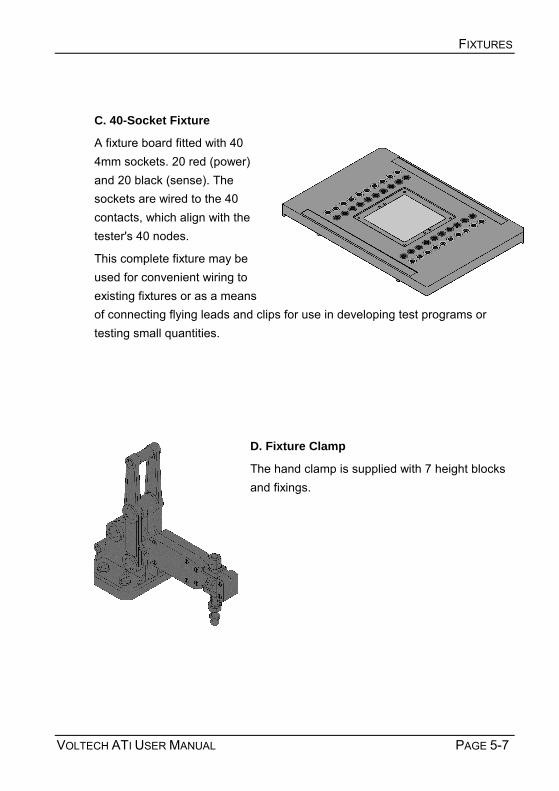
FIXTURES
VOLTECH ATI USER MANUAL PAGE 5-7
C. 40-Socket Fixture
A fixture board fitted with 40 4mm sockets. 20 red (power) and 20 black (sense). The sockets are wired to the 40 contacts, which align with the tester's 40 nodes.
This complete fixture may be used for convenient wiring to existing fixtures or as a means of connecting flying leads and clips for use in developing test programs or testing small quantities.
D. Fixture Clamp
The hand clamp is supplied with 7 height blocks and fixings.

FIXTURES
PAGE 5-8 VOLTECH ATI USER MANUAL
5.2.1 BASIC FIXTURE PLATE
Fixture Plate Components
1. Base Plate
Already fitted with 20 pairs of contacts, the base plate fits into the top of the tester and makes electrical connection to the testers 20 pairs of test nodes. The base plate has moulded indents and guides to ease the fitting and wiring of larger test sockets and posts for flying leads. 2. Cover Plate This mounting plate allows convenient attachment of various sockets and connectors. Please note that this plate is only 1mm in thickness and is therefore not suited for probe or Kelvin pin mounting. Refer to the Custom Fixture Kit for this purpose.
The Fixture Plate may be used to mount existing test fixtures onto an AT Series Tester, or to create test fixtures for flying lead parts where spring probes are not required.
1
2

FIXTURES
VOLTECH ATI USER MANUAL PAGE 5-9
5.2.2 CUSTOM FIXTURE KIT The Custom Fixture Kit enables many types of transformers and other wound components to be quickly and securely connected to an AT Series tester for fast and accurate testing.
The system can accommodate transformer sizes of up to 63.5mm (2.5) and, with suitable probes, parts with surface mounting, pin, blade or flying lead connections can be connected.
The fixture system is supplied as detailed in the comprehensive user guide to fixture construction. The kit is designed such that fixtures can be quickly assembled using a basic vertical drill and simple hand tools.
Fixture Kit Components
1. Base Plate
Already fitted with 20 pairs of contacts, the base plate fits into the top of the tester and makes electrical connection to the testers 20 pairs of test nodes.
2
1
3
5 4

FIXTURES
PAGE 5-10 VOLTECH ATI USER MANUAL
The base plate has moulded indents and guides to ease the fitting and wiring of larger test sockets and posts for flying leads.
2. Probe Housing Box
This 9mm thick plate is designed especially to hold a wide range of ATE probes and Kelvin pins.
3. Clamp An optional hand clamp holds the test piece against the test probes. The clamp is adjustable in height and in spring pressure. Voltech Part No. 91-187
4. Guides
12 adjustable guides are supplied to locate the test piece in the fixture quickly and accurately.
5. Drilling Tools
5 different pitches of template are available for marking and drilling the holes for test probes or Kelvin pins.
To enable the probe housing box and the test piece interface plate be drilled to the accuracy required, drilling templates are available in the following grid pitches:
1.27mm, 2.00mm, 2.50mm, 2.54mm and 3.81mm
Pack of 5 (1 of each pitch) drilling templates. Voltech Part No. 50-307

FIXTURES
VOLTECH ATI USER MANUAL PAGE 5-11
5.2.3 40 SOCKET FIXTURE
Where Used
Ideal for developing test programs or testing small batches of different wound components. The 40 Socket Fixture consists of 20 pairs of red and black 4mm shrouded safety sockets mounted and wired into a blank fixture.
A variety of clips and posts can be used to enable connection to the component under test.
When testing larger quantities of the same component (50 or more) then a custom fixture solution is strongly recommended. Ask your Voltech supplier for details of the Custom Fixture Kit.
Red Terminal (Power)
Black Terminal (Sense)

FIXTURES
PAGE 5-12 VOLTECH ATI USER MANUAL
5.3 FIXTURE SYSTEM SPECIFICATION
The Voltech custom fixture is designed to connect to wound components with the following characteristics:
Size:
A footprint of up to 63.5mm square
A height of up to 63.5mm
A connection matrix up to 60mm square
Connection types:
Surface mount
Pin connection
Blade connection
Flying leads
Pitches of:
1.27mm
2.00mm
2.50mm
2.54mm (0.1)
3.81mm (0.15)
There are some application limitations to the above; for example, the minimum pitch of the blade type that can be connected to is determined by the minimum pitch that the necessary connector can be put on.
Also though a 1.27mm pitch is available it is only anticipated that component connections will be on multiples of this pitch and there will not be two connections only 1.27mm apart.

FIXTURES
VOLTECH ATI USER MANUAL PAGE 5-13
Compatible connection types
Kelvin clips
Kelvin blades
4mm sockets
ATE pin types
Rotary point
Castellated
Point
Cup
Crown
5.4 FIXTURE PARTS AVAILABLE FROM VOLTECH
A number of components parts and kits are available from your Voltech supplier to help you assemble your own fixtures.
MORE INFORMATION: A comprehensive guide to the construction of your own custom fixtures is supplied with each custom fixture plate kit. A copy of the guide is also available on the ATi CD-ROM in Adobe PDF format.
Please contact your Voltech supplier for more information or visit our website at www.voltech.com for details.
i

FIXTURES
PAGE 5-14 VOLTECH ATI USER MANUAL
Example probe box drilled for multiple RM bobbin types
M Series Kelvin Fixture

FIXTURES
VOLTECH ATI USER MANUAL PAGE 5-15
5.4.1 FIXTURE PLATE (VOLTECH PART NUMBER 91-184) Designed for mounting existing fixtures to an AT series tester, the fixture plate comprises:
Item 1 Base plate (including contact pins) with cover
Item 2 Test piece interface plate
Fittings and fasteners for above.

FIXTURES
PAGE 5-16 VOLTECH ATI USER MANUAL
5.4.2 CUSTOM FIXTURE KIT (VOLTECH PART NUMBER 91-185) A kit of parts for constructing your own fixtures. Interconnecting wire, test probes or clips and a drilling template will also be required. The custom fixture kit comprises:
Item 1 Base plate (including contact pins) with cover
Item 2 Test piece interface plate
Item 3 Probe housing box
Item 4 Bezel
Item 5 Guides (12 off)
Fixings for above.
5.4.3 SOCKET FIXTURE (VOLTECH PART NUMBER 91-186) A fixture board fitted with 40 4mm sockets. 20 red (power) and 20 black (sense). The sockets are wired to the 40 contacts, which align with the tester's 40 nodes.
This fixture may be used for convenient wiring to existing fixtures or as a means of connecting flying leads and clips for use in developing test programs or testing parts in a design laboratory.

FIXTURES
VOLTECH ATI USER MANUAL PAGE 5-17
5.4.4 CONNECTION LEAD SET (VOLTECH PART NUMBER 78-030) A selection of Kelvin and non-Kelvin crocodile clips and spring-loaded posts are available from Voltech, called the 'Connection Lead Set'
Each of the 'clips' is finished with 200mm red and black leads terminated in 4mm plugs.
The connection lead set consists of: 10 Spring-loaded connection posts
10 Kelvin crocodile clips
10 Non-Kelvin crocodile clips
10 Fine non-Kelvin clips
5.4.5 CLAMP (VOLTECH PART NUMBER 91-187) The hand clamp is supplied with 7 height blocks and fixings.
5.4.6 TOOLING Drilling templates are available in a variety of sizes (1.27mm, 2.00mm, 2.50mm, 2.54mm, 3.81mm) and are sold as a pack.
Pack of 5 (1 of each pitch) drilling templates. Voltech Part No. 50-307

FIXTURES
PAGE 5-18 VOLTECH ATI USER MANUAL
5.5 KELVIN CONNECTIONS
Kelvin or 4terminal connections are commonly used in precision measurement systems to obtain accurate measurements of impedance. Each of the ATis 20 measurement nodes (including the BNC connectors) consists of two terminals (Power and Sense) to allow complete 4-terminal testing.
Why use Kelvin connections?
Consider measuring a perfect 1.000 ohm resistor to check that it is within its 1% tolerance at dc.
In a standard 2 terminal measurement, there are TWO sources of error:
The resistance of the connecting leads.
The resistance of the contact between the connection and the lead of the resistor.
RL, the resistance of the leads, is fixed and can be compensated for. Lets assume it is 2mΩ for good quality leads.
RC, the connection or contact resistance is a variable and cannot be compensated for. RC will vary with the cleanliness of the leads and connector, the pressure applied and the contact surface area--all of which can be difficult to control. Lets assume RC varies from a few mΩ to tens of mΩ, but is typically 5 mΩ.

FIXTURES
VOLTECH ATI USER MANUAL PAGE 5-19
2-wire measurement circuit
The measurement system applies 100.0mV dc to the leads, measures the current flowing, and divides V by I to obtain R the dc resistance. R = V / I
In this case, the total resistance of the circuit is 2 + 5 + 1000 + 5 + 2 = 1014 mΩ.
I = 100 / 1014 = 98.62mA
2-wire R = V / I = 100 / 98.62 = 1.014 ΩΩΩΩ
2 wire R= 1.014ΩΩΩΩ
This shows that the resistor is +1.4% and out of tolerance when it is really exactly 1.000 Ω
Notice also, that the voltage applied to the resistor is NOT exactly 100mV because of the voltage drops across RL and RC.
In a Kelvin or 4-terminal connection, the voltage is applied in exactly the same way through a pair of Power leads, but the voltage is MEASURED using an extra pair of Sense leads. The voltage measuring circuit is designed to have a very high input impedance (10MΩ on the ATi) and so negligible current flows in the Sense leads, there being a negligible error in the voltage measurement.
R = 1.000Ω
V = 100mV
RL RL
RC RC
2mΩ
5mΩ 5mΩ

FIXTURES
PAGE 5-20 VOLTECH ATI USER MANUAL
4-wire measurement circuit
The current flowing is the same:
I = 100.0mV / 1014mΩΩΩΩ = 98.62mA
But the voltage measured is now: 1.000Ω x 98.6mA = 98.6mV
And the dc resistance calculated is:
VM/R = 98.6mV / 98.6mA = 1.000ΩΩΩΩ
4-wire R = 1.000ΩΩΩΩ
The correct result.
In general, a true Kelvin connection provides the most accurate means of sensing the voltage across any impedance (AC or DC) and hence helps to produce an accurate measurement of that impedance without errors due to lead and contact resistance. The voltage measured can also be used to trim Vm to the desired voltage.
R = 1.000Ω
V = 100mV
Vm
RL RLRL RLRL
I Im 0≅ I
I
RC RCRC RCRC
2mΩ 2mΩ2mΩ 2mΩ 2mΩ2mΩ
5mΩ 5mΩ5mΩ 5mΩ 5mΩ5mΩ
P- P+S- S+
2mΩ
5mΩ

FIXTURES
VOLTECH ATI USER MANUAL PAGE 5-21
Ideally, all impedance measurements would be made using Kelvin connections. However, many terminals do not permit the use of four wires all the way to the body of the component under test.
In such cases, separate power and sense leads are used up to the base of the terminal, and the length of common lead (from the junction of the power and sense leads, through the terminal and the component lead to the body of the component) should be kept to a minimum.
The common lead length is shown as AA and BB in the diagram below.
Semi-Kelvin Connection
D. U. T.
V = 100mV
Vm
I I
I
P- P+S- S+
A’
AB
B’

FIXTURES
PAGE 5-22 VOLTECH ATI USER MANUAL
The AT Series testers provide all the connections required to take advantage of Kelvin measurements.
A test node may be considered to be a pair of connections consisting of one power and one sense terminal.
The following diagram indicates how to identify the node terminal function:
POWER terminals are all on the outside of the fixture area.
SENSE terminals are all on the inside of the fixture area.
The BNC to clip leads supplied with your ATi provide true 4-terminal Kelvin connections.
IMPORTANT: Kelvin four terminal connections are generally advised to be used in all test fixtures; they are essential for transformers whose winding resistance’s are less then 1ΩΩΩΩ.
i

FIXTURES
VOLTECH ATI USER MANUAL PAGE 5-23
When Kelvin connections are not possible because of space limitations, use a semi-Kelvin connection. Below are two examples of Kelvin connections:
Clips supplied with BNC leads Kelvin pins

FIXTURES
PAGE 5-24 VOLTECH ATI USER MANUAL

VOLTECH ATI USER MANUAL PAGE 6-1
6 FRONT-PANEL MODES

FRONT-PANEL MODES
PAGE 6-2 VOLTECH ATI USER MANUAL

FRONT-PANEL MODES
VOLTECH ATI USER MANUAL PAGE 6-3
Contents – Front-panel Modes
6.1. LCR MODE BASIC FUNCTIONS.................................................................6-5 6.1.1. LCR (BNC) Mode ........................................................................................ 6-7 6.1.2. LCR (FIX) Mode ........................................................................................ 6-11 6.1.3. Insulation Resistance ................................................................................ 6-13
6.2. TESTS AVAILABLE IN THE LCR MODES...................................................6-17 6.3. LCR MENUS..........................................................................................6-19
6.3.1. LCR (BNC) Menu ...................................................................................... 6-19 6.3.2. LCR (FIX) Menu ........................................................................................ 6-20 6.3.3. LCR Mode Settings ................................................................................... 6-21
6.4. COMPENSATION.....................................................................................6-29 6.4.1. Performing Compensation......................................................................... 6-31 6.4.2. Compensation Fail .................................................................................... 6-33
6.5. LCR MODE ERROR MESSAGES..............................................................6-35 6.6. PROGRAM MODE ...................................................................................6-39
6.6.1. Creating a New Test Program................................................................... 6-40 6.6.2. Setting Up Test Program Options.............................................................. 6-44 6.6.3. Running a Test Program ........................................................................... 6-47 6.6.4. Password Protection ................................................................................. 6-48

FRONT-PANEL MODES
PAGE 6-4 VOLTECH ATI USER MANUAL

FRONT-PANEL MODES
VOLTECH ATI USER MANUAL PAGE 6-5
6.1 LCR MODE BASIC FUNCTIONS As well as executing complete test sequences at high speed on multiple windings for production testing, the ATi can make LCR and turns ratio-type measurements on a component or single winding without using the PC-based test program editor. Measures L, C, R (DC and AC), Z, θθθθ, X, Q, D, Turns Ratio, Leakage Inductance and Insulation Resistance.
All parameters required to fully characterize a winding or component.
BNC to Kelvin clip leads provided for accurate 4-terminal measurements.
Quick and easy connection eliminates contact resistance errors.
Intuitive softkey control sets up measurements in a few key presses.
Ready to test in a few seconds
Ideal for design and prototyping of wound components.
Rapid change of test and test conditions without programming.
Fully-automatic or manual test voltage and frequency.
Automatic test conditions for quick, accurate results or fully programmable almost infinite steps of voltage and frequency for complete control.
Inductance and AC resistance tests with bias.
Test windings designed to operate with a DC current bias
Simultaneous large character display of two parameters and test conditions.
Easy to read, no hidden factors or warnings.

FRONT-PANEL MODES
PAGE 6-6 VOLTECH ATI USER MANUAL
From the top-level display:
Two 'LCR' modes are available.
LCR (BNC) mode uses the flexible leads attached to the four connectors on the control panel of the ATi to perform LCR (Inductance, Capacitance, Resistance)-type measurements on a single winding or component.
LCR (FIX) mode uses nodes 13, 14, 15 and 16 of the fixture bay to perform LCR-type measurements plus Turns Ratio, Leakage Inductance and Interwinding Capacitance on two windings of a transformer. The LCR fixture supplied with your ATi provides full-Kelvin (four-wire) connections to these nodes for convenient testing. In LCR (FIX) mode, nodes 13 and 15 are assumed to connect to the primary or energized winding of the transformer; nodes 14 and 16 to the secondary.

FRONT-PANEL MODES
VOLTECH ATI USER MANUAL PAGE 6-7
6.1.1 LCR (BNC) MODE Press the LCR (BNC) softkey, and the ATi immediately begins to make measurements.
Ensure that DC Bias current is switched off before connecting and disconnecting component under test.
The upper measurement is that of the parameter selected by the 1st (upper) softkey. In this case, Ls, the series equivalent inductance, is 3.4556mH.
The second measurement is that of the parameter selected by the 3rd softkey. In this case, Q, the quality factor, is 1.4427.
The next line shows the LCR mode that you are using. This may be either BNC mode or Fixture mode. If compensation is required (see later), this line will also say 'comp req'.
Prg: AUTO V, AUTO Hz
These are the programmed measurement conditions. By default, the ATi automatically chooses measurement conditions that optimize the measurement accuracy. Sometimes these conditions may not be appropriate for the final application of the part under test or may be different to those

FRONT-PANEL MODES
PAGE 6-8 VOLTECH ATI USER MANUAL
chosen on other equipment. See later sections of this chapter for how to program the measurement conditions of your choice.
Mes: 10mV, 3.78mA, 100Hz
These are the measured test conditions. The voltage and frequency are measured at the sense terminals of the ATi. If you are using Kelvin (4-wire) connections, then these are the conditions measured on the connectors of the part under test. Usually, the voltage and frequency will be identical to the programmed voltage and frequency, because the ATi always attempts to trim its output voltage across the part to be equal to the desired or program voltage (see below). If the impedance of the part is very low, the ATi might not be able to supply sufficient current to maintain the programmed voltage. In this case, the voltage measured will be less than the program voltage.
The current passing through the part is also displayed on this line. A constant current can be programmed for some tests.
The ATi is applying the test signal to BNC terminals on the control panel in the following way:
Note: The BNC connectors are also connected internally to nodes 20 (P+ and S+) and 18 (P- and S-) of the fixture bay.
Program v
Winding under test
P- S- S+ P+
i
Measured v

FRONT-PANEL MODES
VOLTECH ATI USER MANUAL PAGE 6-9
Remove any fixture from the fixture bay and ensure these nodes (18 and 20) are clear before using the BNC terminals.
The top softkey (number 1) allows you to move through the visible options.
Press softkey 1, and you will see:
Lp and Q
The options for the second display line have changed as appropriate and can be changed by pressing the softkey 3.

FRONT-PANEL MODES
PAGE 6-10 VOLTECH ATI USER MANUAL
Lp and D
More tests are available by pressing 'More (1/3)', softkey 2:
Z and θ
Please see the sections following LCR (FIX) for details of how to use the front-panel LCR modes of the ATi.

FRONT-PANEL MODES
VOLTECH ATI USER MANUAL PAGE 6-11
6.1.2 LCR (FIX) MODE Press the LCR (FIX) softkey, and the ATi immediately begins to make measurements.
Ensure that DC Bias current is switched off before connecting and disconnecting component under test.
The ATi is making measurements on nodes 13 and 15 (the 'primary') and nodes 14 and 16 (the 'secondary'). The LCR fixture supplied with your ATi has four Kelvin leads already connected to these nodes.

FRONT-PANEL MODES
PAGE 6-12 VOLTECH ATI USER MANUAL
To change from measurements on the primary (nodes 13, 15) to measurements on the secondary (nodes 14, 16) press softkey 5, 'Pri Sec'.
For measurements of TR (turns ratio) and TRL (turns ratio by inductance), softkey 5 toggles the display of measured test conditions. It does NOT alter the designation of primary (13,15) and secondary (14,16). Turns ratio is always displayed as the ratio between primary (13,15) and secondary (14,16) windings.

FRONT-PANEL MODES
VOLTECH ATI USER MANUAL PAGE 6-13
By default, the number of primary turns is assumed to be 1. In this example:
Np : Ns
1 : 0.365
To display the actual number of turns as measured, enter the number of primary turns by pressing the appropriate buttons on the numeric keypad. (Note: Only numbers and a decimal place can be entered for Np.) E.g.,
Np = 1000
Np : Ns
1000 : 365
The number of primary turns entered will be retained by the tester until the More softkey is selected, i.e., if you exit LCR (FIX) and re-enter or if you select TRL, LL or C, the value for Np remains the same.
6.1.3 INSULATION RESISTANCE Insualtion resistance measurements involve applying a relatively high DC voltage to the part under test in order to measure a high value of resistance. Because of the high voltages involved, IR meaurements operate in a slightly different way to other tests. There is a separate voltage setting menu and ON /

FRONT-PANEL MODES
PAGE 6-14 VOLTECH ATI USER MANUAL
OFF contols are provided for maximum operator safety.
To measure insulation resistance, select IR from either the LCR (BNC) or LCR (FIX) modes.
CAUTION: The insulation resistance test can generate voltages of up to 500V DC. Although the available energy of the source has been limited in accordance with EN61010-1, care should be taken to avoid accidental or unexpected electrical shocks. For this reason, the high-voltage insulation resistance source must be turned on by pressing softkey 3 every time this screen is displayed.
When softkey 3, HV Off On is pressed, the high voltage is applied to the chosen nodes, On is shown in reverse video, and both the program and measured voltages are shown at the bottom of the display.
Press softkey 3HV Off On to switch off the high voltage when handling or connecting the part under test.
Press softkey 6, EXIT to return to the main LCR sreen.
!

FRONT-PANEL MODES
VOLTECH ATI USER MANUAL PAGE 6-15
Settings for the voltage integration can be changed by pressing softkey 4, Settings. A 'Print' option is included in this menu.
Press softkey 1 IR Voltage
And then press 'Enter V' to adjust the IR Voltage.

FRONT-PANEL MODES
PAGE 6-16 VOLTECH ATI USER MANUAL
Enter the required test voltage using the 12-key numeric keypad.
Press softkey 1, ENTER, to accept the value that you have typed.
Press softkey 5, CANCEL, to discard changes and return to the previous menu.
Press softkey 4, DELETE, to correct mistakes.
Insulation resistance set-ups cannot be stored in memory, but the voltage and used nodes are automatically stored and recalled the next time that IR is selected.
The 'Integration', 'Print' and 'More Tests' settings are common to all LCR measurements and are described later in this chapter.

FRONT-PANEL MODES
VOLTECH ATI USER MANUAL PAGE 6-17
6.2 TESTS AVAILABLE IN THE LCR MODES The available combinations are:
More (1/4)
Softkey 1 Softkey 3
Ls Q, D, Rs
Lp Q, D, Rp
Cs D, Q, Rs
Cp D, Q, Rp
More (2/4)
Softkey 1 Softkey 3
Z θ, Q, D
R X
More (3/4)
Softkey 1 Softkey 3
Rdc
IR Off, On
More (4/4) LCR (FIX) only
Softkey 1 Softkey 3
TR POL, PHAS
TRL POL
LL
C
The active display combination is always shown in inverse video.
The results are always shown to 5 significant figures, using normal engineering notation and normal symbols for the units of measurement.

FRONT-PANEL MODES
PAGE 6-18 VOLTECH ATI USER MANUAL
The symbols used are:
Measurement Symbol Units Display Units
DC Resistance Rdc Ohms Ω
DC Resistance Using High- voltage Source
IR Ohms Ω
AC Resistance Series Circuit Rs Ohms Ω
AC Resistance Parallel Circuit Rp Ohms Ω
Inductance Series Circuit Ls Henries H
Inductance Parallel Circuit Lp Henries H
Capacitance Series Circuit Cs Farads F
Capacitance Parallel Circuit Cp Farads F
Interwinding Capacitance C Farads F
Quality Factor Q
Dissipation Factor or tanδ D
AC Impedance Magnitude of Complex Impedance
Z Ohms Ω
Phase Angle of Impedance θ Degrees °
AC Reactance Imaginary Part of Impedance
X Ohms jΩ
Turns Ratio TR
Turns Ratio by Inductance TRL
Polarity POL
Interwinding Phase PHAS Degrees °
Leakage Inductance LL Henries H
Please see the chapter Tests and Test Conditions for a detailed description of each of these measurements and their application.

FRONT-PANEL MODES
VOLTECH ATI USER MANUAL PAGE 6-19
6.3 LCR MENUS See the previous section for details of the tests that are available.
The following flow diagrams describe the menu structure for LCR (BNC) and LCR (FIX) modes.
6.3.1 LCR (BNC) MENU
LCR (BNC)
LCR (FIX)
Execute
Program
Self-Test
R
More (2/3)
Q D
Settings
EXIT
Signal
Integration
Compensate
OK
Enter f
Enter V
Enter I
Enter IBias
OK
Lp Cs Cp
More (1/3)
D Rs
Settings
EXIT
Ls
Q
Z
θθθθ
IR
More (3/3)
Settings
EXIT
Rdc
AUTO
AUTO
Short
Long
Cancel
OK
Medium
One All
One All
OK
Short
Open
Fix
Auto
Delete
Enter
Cancel
Shift
IBias XBias
Delete
Enter
Cancel

FRONT-PANEL MODES
PAGE 6-20 VOLTECH ATI USER MANUAL
6.3.2 LCR (FIX) MENU
LCR (BNC)
LCR (FIX)
Execute
Program
Self-Test
R
More (2/4)
Q D
Settings
Sec
EXIT
Signal
Integration
Compensate
OK
Enter f
Enter V
Enter I
Enter IBias
Sec
OK
Lp Cs Cp
More (1/4)
D Rs
Settings
Sec
EXIT
Ls
Q
Z
θθθθ
IR
More (3/4)
Settings
Sec
EXIT
Rdc
Pri
One All
One All
OK
Short
Open
Fix
Auto
Delete
Enter
Cancel
Shift
Pri
Pri
TRL LL C
More (4/4)
PHAS
Settings
Mes Sec
EXIT
TR
POL
Pri
Pri
Short
Long
Cancel
OK
Medium
IBias XBias
Delete
Enter
Cancel

FRONT-PANEL MODES
VOLTECH ATI USER MANUAL PAGE 6-21
6.3.3 LCR MODE SETTINGS For maximum convenience and ease of use, the ATi automatically chooses the voltage and frequency at which the LCR mode tests are carried out.
The test conditions can also be programmed to fixed values to match the specification of a part or to ensure that a batch of parts are tested at exactly the same conditions.
The LCR mode settings screen allows you to:
• Enter fixed voltage and frequency test conditions.
• Compensate for the effect of stray inductance and capacitance from the connection to the part under test.
• Change the level of integration applied to the measurements.
• Print the current measurements to a standard printer.
• Measure on the front panel using any of the tests that have been purchased.
This section describes the measurement settings that are available in both LCR (BNC) and LCR (FIX) modes.
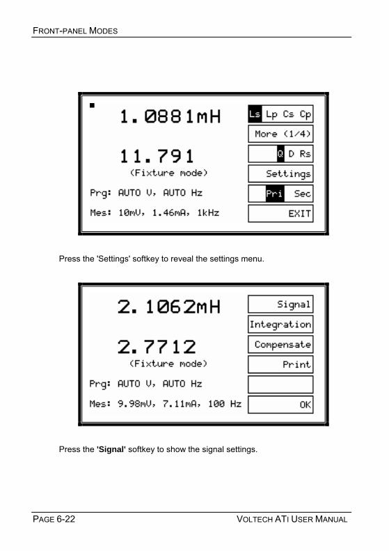
FRONT-PANEL MODES
PAGE 6-22 VOLTECH ATI USER MANUAL
Press the 'Settings' softkey to reveal the settings menu.
Press the 'Signal' softkey to show the signal settings.

FRONT-PANEL MODES
VOLTECH ATI USER MANUAL PAGE 6-23
Note that in LCR (BNC) mode there is only one set of conditions to choose and that the 'Pri Sec' softkey is thus not shown. On the bottom line of this display, the last measurement and its measurement conditions are displayed if they are available.
ENTER f, ENTER V and ENTER Ibias
These keys allow you to enter fixed values of voltage, frequency and DC bias
current using the 12-key numeric keypad.
The combination of AUTO f and a fixed value of voltage is NOT allowed. Hence, you must always enter a fixed frequency before entering a fixed voltage.
You may enter a DC bias current when any measurement is displayed, but bias is not applied during C, Cs or Cp measurements.
To enter, for example, a fixed frequency, press ENTER f (softkey 1) on the previous screen and you will see:

FRONT-PANEL MODES
PAGE 6-24 VOLTECH ATI USER MANUAL
Press Fix to enter the value currently being measured by the ATi. (This does not apply to Ibias, the DC bias current.)
Press Enter to accept the value that you have entered.
Press Auto to have the ATi automatically choose a voltage or frequency. (Remember that the combination of AUTO f and a fixed voltage is not allowed.)
Press Cancel at any time to discard any changes that you have made and to return to the previous screen.
The ‘Shift’ key is used to enter the multipliers k (x1,000) or M (x 1,000,000). Ibias is always entered and displayed in mA. There are no multipliers for Ibias.
To enter 10.5 kHz, for example:
Either press 1, 0, 5, 0, 0, ENTER f
or press 1, 0, ., 5, SHIFT, 5, ENTER f

FRONT-PANEL MODES
VOLTECH ATI USER MANUAL PAGE 6-25
When the Shift key (softkey 6) is pressed, it is shown in reverse video.
Press 5 with the Shift key in reverse to enter the multiplier k (x1,000).
Press 6 with the Shift key in reverse to enter the mulitiplier M (x1,000,000).
Press softkey 4, Delete, to correct mistakes.
The value is changed when you press the Enter' softkey.
Pressing Cancel will return you to the previous screen.

FRONT-PANEL MODES
PAGE 6-26 VOLTECH ATI USER MANUAL
New settings are diplayed as above, once they have been stored. Since no measurements have been made with these new conditions, measured values cannot be displayed on bottom line.
Having entered fixed values of voltage, frequency and Ibias as required, and pressed softkey 6 OK, the screen will show:
The Bias level is only shown when its program value is not zero.
Press 'OK' again to return to the normal measuring menu.

FRONT-PANEL MODES
VOLTECH ATI USER MANUAL PAGE 6-27
Note that 'com req' is now displayed because a frequency has been chosen at which compensation measurements have not been made before. For accurate measurements, compensation should now be appiled. See the compensation section in this chapter for details.
Press the 'Integration' softkey on the settings menu to reveal the integration options.
The integration level controls details of the measurement method including the number of readings that are averaged together to provide the displayed measurements. To achieve the specified accuracy of the ATi, the default 'Medium' measurement should be chosen.
Choosing 'Short' integration will provide faster but less stable and accurate results.
For maximum stability and accuracy, choose 'Long' integration.
Compensation
Compensation is described in detail in the next section.

FRONT-PANEL MODES
PAGE 6-28 VOLTECH ATI USER MANUAL
Press the 'Print' softkey in the settings menu, and the measurement information displayed will be output to the printer port of the ATi.
Measurements can be recorded on any standard printer with a conventional PC-type parallel centronics input. The output is formatted using standard codes, so that a simple 40-column ticket printer may be used. ------------------------------------- DATE: 30-JAN-02 14:55:26 LS : 27.138uH Q : 16.785 (BNC comp req) Prg: AUTO V, 123Hz Mes: 1000mV, 1.33mA, 123Hz -------------------------------------

FRONT-PANEL MODES
VOLTECH ATI USER MANUAL PAGE 6-29
6.4 COMPENSATION
Measurements on the ATi can be compensated for the effects of stray connection capacitance and inductance that are always present. The effect of the strays upon the measurement will vary significantly with the part being tested, but for optimum accuracy Voltech recommends that all reference measurements should be made after compensation.
The ATi is fully compensated at the factory for a broad range of frequencies, and compensation is often not required when using the LCR modes. If compensation is required, one of the following measurements will be displayed:
(BNC comp req)
(Fixture comp req)
Once compensation measurements have been carried out at a particular frequency, those measurements will be stored and need not be repeated again.
Measured V
Program V
Winding under test
P- S- S+ P+

FRONT-PANEL MODES
PAGE 6-30 VOLTECH ATI USER MANUAL
To compensate for the effect of stray inductance, the ATi must make a measurement with a short-circuit in place of the winding(s) under test. This is called short-circuit compensation.
The short-circuit should be made of a piece of copper wire that is as short as possible. If you are making measurements using a fixture plate, it is usually convenient to make a part up with short-circuits in place of the windings on a sample bobbin without cores.
Transformer Shorting bobbin for compensation
To compensate for the effect of stray capacitance, the ATi must make a measurement with no winding(s) in place.
This is called open-circuit compensation.
The DC resistance test (Rdc) uses short circuit compenstion only; the other LCZ measurement require both. Once L, C or Z is compensated, this
compensation is stored and applied to any L,C or Z measurement as long as the measurement conditions and nodes are not changed.
Compensation values are unique to the voltage and frequency test conditions and, thus, you must re-compensate if any of these values are changed. The display will always show comp req when valid compensation measurements are not available.

FRONT-PANEL MODES
VOLTECH ATI USER MANUAL PAGE 6-31
6.4.1 PERFORMING COMPENSATION To perform compensation, press softkey 3, Compensate, in either the LCR (BNC) or LCR (FIX) settings menus. You will see:
If you have chosen a frequency that has not already been compensated, that frequency will be displayed as above. The 'One' short or open-frequency compensation options will be available if you have chosen any fixed frequency. Choosing 'One' sets up the ATi to perform compensation measurements at the chosen frequency only and is the preferred choice. Choosing 'All' will set up the tester to re-compensate at all frequencies, and this can take up to two minutes or more and is not normally necessary. 'All' is the only available choice if the ATi is set up with an 'Auto' frequency.
To perform short-circuit compensation for stray inductance and resistance, first short circuit together all the nodes (in this case, clip the alligator clips of the BNC leads together) and press softkey 1 'Short; and select One or 'All'.

FRONT-PANEL MODES
PAGE 6-32 VOLTECH ATI USER MANUAL
To perform open-circuit compensation for stray capacitance, remove all parts under test but leave the BNC leads or test fixture in place and press softkey 2 'Open' and select One' or 'All'.For optimum accuracy, place any leads or other connectors that can move in a position as close as possible to that which will be used when making measurements.
Press softkey 5 Start begin the compensation process.
Press softkey 6 OK to use any compensation measurements that have just been made and return to the previous LCR screen.
During short or open circuit compensation, the ATi is making very accurate measurements of the small stray or parasitic components. Remember that the power & sense terminal of each node must be connected together. The

FRONT-PANEL MODES
VOLTECH ATI USER MANUAL PAGE 6-33
measurement may take up to 2 minutes, during which you will see the following display:
Press softkey 5, CANCEL, at any time to cancel or stop the compensation measurement, and you will be returned to the previous screen.
Once both short and open circuit compensation have been performed succesfully, the words comp req' will be removed from the compensation screen and from the main LCR or Rdc IR measurement screen.
See Section 6.1.2 for node #s when performing LCR (FIX) mode compensation.
6.4.2 COMPENSATION FAIL Should any compensation measurement fail, this is most likely because either the short circuit (S/C COMP) or the open circuit (O/C COMP) were not connected properly.

FRONT-PANEL MODES
PAGE 6-34 VOLTECH ATI USER MANUAL
Check the connection (either short or open circuit ) and repeat the compensation measurement.
In the unlikely event that compensation continues to fail, you can use the ATi without compensation (comp req' will be shown on the display), while contacting your Voltech supplier for applications assistance.

FRONT-PANEL MODES
VOLTECH ATI USER MANUAL PAGE 6-35
6.5 LCR MODE ERROR MESSAGES
The ATi is a precision measuring instrument with fully programmable test sources. The ATi will, whenever possible, ensure that the programmed voltage, frequency and DC bias current are present AT THE TERMINALS OF THE PART UNDER TEST.
This is done by measuring the voltage and current at the terminals of the part and, if necessary, trimming the test source to establish exactly the required conditions at the part.
This means that the ATi will automatically compensate for lead resistance and (if 4-wire Kelvin connections are used) the contact resistance between connector and the part under test.
ATi basic measurement circuit. Measured V = Program V
This is very different to commonly used LCR bridges, which have a nominal impedance in their output to provide short circuit protection for the test signal generator.
Measured V
Program V +
Winding under test
P- S- S+ P+

FRONT-PANEL MODES
PAGE 6-36 VOLTECH ATI USER MANUAL
Other measurement circuit. Measured V ≠≠≠≠ Program V
There are circumstances when the ATi cannot maintain the measured voltage to be equal to the program voltage. For example, if the AC impedance of the winding under test is only 0.1Ω at the specified frequency, and you have specified a 5V test signal, then the AT would have to supply 5V / 0.1Ω = 50 Amps, and this is not possible.
Under these circumstances, the ATi display of both program and measured voltages will clearly show the difference.
Measured V
Program V
Winding under test
50Ω
P- S- S+ P+
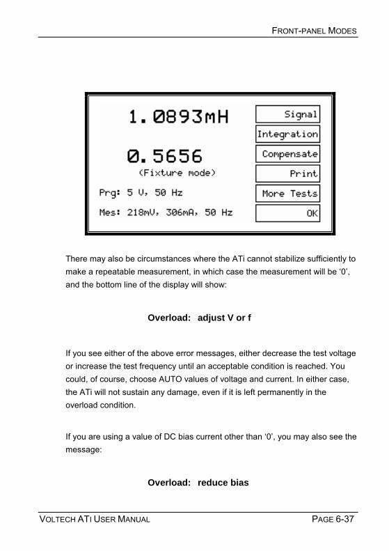
FRONT-PANEL MODES
VOLTECH ATI USER MANUAL PAGE 6-37
There may also be circumstances where the ATi cannot stabilize sufficiently to make a repeatable measurement, in which case the measurement will be 0, and the bottom line of the display will show:
Overload: adjust V or f
If you see either of the above error messages, either decrease the test voltage or increase the test frequency until an acceptable condition is reached. You could, of course, choose AUTO values of voltage and current. In either case, the ATi will not sustain any damage, even if it is left permanently in the overload condition.
If you are using a value of DC bias current other than 0, you may also see the message:
Overload: reduce bias

FRONT-PANEL MODES
PAGE 6-38 VOLTECH ATI USER MANUAL
in which case, you should reduce the bias level until a result is displayed.
If you make a mistake choosing test parameters, the ATi will sound a short beep and return to the previous screen condition. Examples are attempting to enter AUTO frequency when a fixed voltage has already been entered or entering a value outside the specification of the ATi - such as 10MHz for test frequency.

FRONT-PANEL MODES
VOLTECH ATI USER MANUAL PAGE 6-39
6.6 PROGRAM MODE
As well as using the AT Editor software to create test programs for the ATi, programs for your ATi tester may be created directly from the instruments front panel.
From the top-level menu, choose softkey 1, Programs.
The resulting programs screen displays a list of programs available in the local or Server program store, depending upon the general program store set-up of the tester, which you may choose to:
a) run at this time by pressing the Run softkey,
b) change the set-up of by choosing Set-Up or
c) delete from the program store by choosing Delete.
Or, you may choose to create a new test program directly from the front panel.

FRONT-PANEL MODES
PAGE 6-40 VOLTECH ATI USER MANUAL
6.6.1 CREATING A NEW TEST PROGRAM In order to create a new test program, select * New program *, using the arrow softkey, and choose Set-up, softkey 2.
The next screen shown is the test selection screen, initially, with the absence of any tests.

FRONT-PANEL MODES
VOLTECH ATI USER MANUAL PAGE 6-41
To create a new test, select Add, which will take you to the test selection screen for the standard measure mode (see below).
Use the arrow key (softkey 2) to select a test to be set up. For example, scroll down one line, to R Winding Resistance, and press Enter to set up a winding resistance test on your ATi tester.
The next screen that you will see is the set-up screen for the selected test. In this example, the Set up R screen (see below).

FRONT-PANEL MODES
PAGE 6-42 VOLTECH ATI USER MANUAL
Use the arrow key to scroll through and set up the test parameters. For example, to set up limits, scroll to the Limit type line and press softkey 3 three times to enter both minimum and maximum limit values.
Use the down arrow key, again, to scroll to the Minimum limit and Maximum limit lines and enter your limit values from the instrument keypad. For example, enter 59 and 73 using the numeric keypad.

FRONT-PANEL MODES
VOLTECH ATI USER MANUAL PAGE 6-43
Then, scroll down, again, to choose your high and low nodes.
Choose Next. At the following display (see below), you may choose to Measure, if the test that is being set up, supports this functionality. Pressing Measure will update the limits as well as signal and frequency, if those parameters are set to Auto, similar to the Measure button in the AT Editor program.

FRONT-PANEL MODES
PAGE 6-44 VOLTECH ATI USER MANUAL
Choosing OK will return you to the program test selection screen, which should now correctly display the test parameters that have been entered in a table format (see below).
Note: The OK softkey does not allow you to exit the test set-up screen until all required test parameters have been entered.
6.6.2 SETTING UP TEST PROGRAM OPTIONS To set up program options for the test that has been created, select Set-Up. This will take you to the program options screen, where you can now change or

FRONT-PANEL MODES
VOLTECH ATI USER MANUAL PAGE 6-45
set the test program name, fixture ID and all other program options that are also available in the AT Editor software.
For example, under Name, enter TUTORIAL as the program name and under Fix ID, enter UNIVERSAL as your fixture ID. To enter those names, scroll to the appropriate line, use the Delete softkey to delete the default description of PART 1, and then use the instrument keypad to enter your own description.
Note that, on this screen, the shift key is not available for character entry. On the program options screen, the buttons on the instrument keypad will consecutively scroll you through both numbers and letters. Once the character that you want to enter appears in inverse on the LCD, pause briefly, and the chosen letter or number will be entered.
To choose other program options, such as sending test results to the Server, highlight the appropriate line on the program option display and choose On or Off. For example, to automatically send test program results to the AT Server, scroll to Send results to Server: Off and choose softkey 3 On.

FRONT-PANEL MODES
PAGE 6-46 VOLTECH ATI USER MANUAL
Once you have completed the program options set-up, press OK to return to the program test selection screen and OK again to confirm your set-up. Note that, if a password has been set, the AT requests the password to be entered before the program can be saved.
Enter the password on the instrument keypad, using the Shift key to enter letters, if necessary, and press Enter.

FRONT-PANEL MODES
VOLTECH ATI USER MANUAL PAGE 6-47
A Password Valid screen will confirm the correct password entry and return you to the program screen, which now lists the new test program that has been created.
6.6.3 RUNNING A TEST PROGRAM To run the program, use the arrow keys to select it and choose the Run softkey. This will run the test program that has been created from the front panel of the instrument in exactly the same way that a program created by and downloaded from the AT Editor would be run, i.e., you will be prompted to fit the fixture, choose compensation or no compensation, and then run the chosen program by selecting Run.

FRONT-PANEL MODES
PAGE 6-48 VOLTECH ATI USER MANUAL
Running the program will take you to the PASS/FAIL display, where pressing Finish will return you to the program selection screen, where you may choose to re-run the test program, run a different test program, change the set-up of am existing test program, delete a program or create another, new program from the front panel.
6.6.4 PASSWORD PROTECTION The ATis front-panel program mode allows the operator to edit test programs that are stored in the AT Server or the ATs local program store, save new or modified programs or delete test programs directly from the front panel. To help protect existing test programs and their set-up, two AT passwords may be createda Server password and a local password. The Server password helps protect programs stored on the AT Server, whereas the local AT password protects the local program store. When a password has been set up, the instrument will force the operator to enter the correct password before a program can be saved or deleted. The AT Server password must be set up from within the Server software (go to Setup → Password).

FRONT-PANEL MODES
VOLTECH ATI USER MANUAL PAGE 6-49
Setting the Internal AT Password
As well as from within the Editor software (see chapter 3), the internal, local AT password may be set up directly from the main set-up menu of the ATi. From the top-level instrument menu, choose Set-Up. At the set-up screen, choose softkey 2, Set-Up. Use the down arrow key to scroll to the AT Password option and press Change.
If no password has been set, the ATi will immediately prompt for a new password to be entered via the instrument keypad.

FRONT-PANEL MODES
PAGE 6-50 VOLTECH ATI USER MANUAL
If a password has already been set, the existing password must be entered at the screen below, before a new internal password can be set.
The internal AT password protection may be removed by setting the password to a blank password, i.e., not enter any characters. Note: The ATs local password is set as blank by default.

VOLTECH ATI USER MANUAL PAGE 7-1
7 TESTS AND TEST CONDITIONS

TESTS AND TEST CONDITIONS
PAGE 7-2 VOLTECH ATI USER MANUAL
Contents – Tests and Test Conditions
7.1. INTRODUCTION ........................................................................................ 7-4 7.1.1. Choosing Tests for a Transformer............................................................... 7-4 7.1.2. CTY – Continuity ....................................................................................... 7-12 7.1.3. R – DC Resistance.................................................................................... 7-13 7.1.4. R2 – DC Resistance Match....................................................................... 7-16 7.1.5. LS, LP – Inductance (Series and Parallel Equivalent Circuit).................... 7-19 7.1.6. QL – Quality Factor ................................................................................... 7-26 7.1.7. D – Dissipation Factor or Tanδ.................................................................. 7-30 7.1.8. RLS, RLP – AC Resistance (Series and Parallel Circuit) .......................... 7-34 7.1.9. LSB, LPB – Inductance with Bias (Series and Parallel Circuit) ................. 7-38 7.1.10. L2 – Inductance Match............................................................................ 7-42 7.1.11. LL, LLO – Leakage Inductance and Leakage Inductance with Offset ..... 7-45 7.1.12. C – Interwinding Capacitance Test (Parallel Circuit) ............................... 7-50 7.1.13. CS and CP – Capacitance Test (Series and Parallel Circuit).................. 7-55 7.1.14. C2 – Capacitance Match......................................................................... 7-57 7.1.15. TR – Turns Ratio and Phasing................................................................ 7-60 7.1.16. TRL – Turns Ratio by Inductance............................................................ 7-68 7.1.17. LVOC – Low Voltage Open Circuit.......................................................... 7-73 7.1.18. IR – Insulation Resistance ...................................................................... 7-77 7.1.19. GBAL – General Longitudinal Balance.................................................... 7-80 7.1.20. LBAL – Longitudinal Balance .................................................................. 7-85 7.1.21. RESP – Frequency Response ................................................................ 7-89 7.1.22. ILOS – Insertion Loss.............................................................................. 7-93 7.1.23. RLOS – Return Loss ............................................................................... 7-96 7.1.24. Z, ZB – Impedance, Impedance with Bias............................................. 7-100 7.1.25. X – Reactance....................................................................................... 7-103

VOLTECH ATI USER MANUAL PAGE 7-3
7.1.26. ANGL – Phase Angle of Impedance...................................................... 7-105 7.1.27. PHAS – Interwinding Phase Angle........................................................ 7-108 7.1.28. TRIM – Pause Testing in Order to Trim a Component Value ................ 7-111 7.1.29. OUT – Control External Devices ........................................................... 7-113 7.1.30. LSBX – Inductance with External Bias (Series Circuit).......................... 7-116 7.1.31. LPBX – Inductance with External Bias (Parallel Circuit)........................ 7-118 7.1.32. ZBX - Impedance with External Bias..................................................... 7-120
7.2. SERIES AND PARALLEL CIRCUITS .........................................................7-123 7.3. CAPACITOR MEASUREMENTS ...............................................................7-125

TESTS AND TEST CONDITIONS
PAGE 7-4 VOLTECH ATI USER MANUAL
7.1 INTRODUCTION
Tests and Test Conditions
This chapter provides guidance for the use of each of the tests currently available for the ATi. For the latest information please check the Voltech web site at:
www.voltech.com
7.1.1 CHOOSING TESTS FOR A TRANSFORMER
In order for a completed transformer to function properly in its intended application, it should be constructed in accordance with the designers specification.
The test specification (or ATi test program) calls for various electrical parameters to be measured such that the transformer construction is verified.
For example, a measurement of inductance will help to confirm that the correct number of turns has been used with the correct grade of core material and that the cores have been assembled correctly with the right air-gap.
To fully verify the transformer construction, however, a complete series of tests should be carried out.

VOLTECH ATI USER MANUAL PAGE 7-5
Recommended Tests
EXAMPLE: Switched-mode DC-DC converter ferrite power transformer
CTY – Continuity
A continuity check is a very quick test to determine if the transformer has been inserted correctly into the fixture. Used with the Stop on Fail feature of the ATi, the transformer can be re-seated without wasting test time or recording a FAIL.
R – Resistance
Check the DC resistance of every winding to ensure that the correct diameter wire has been used and that it is finished or terminated properly. (A poor solder joint may not show as an out of tolerance inductance, but could lead to a reduced service life for the transformer).
LS – Inductance (Series Circuit)
As described above, an inductance measurement will confirm that the correct number of turns has been wound and that the correct cores have been properly assembled. The test is usually performed on one winding only. If there is no obvious primary winding, use the winding with the greatest number of turns for the best accuracy and stability.
Q – Quality Factor
Q is the ratio between the imaginary (inductive) and real (AC resistive) parts of the windings complex impedance. Measuring the expected Q figure gives further indication that the correct wire, turns and cores have been used. Q is usually measured once only on the primary.
TR – Turns Ratio and Phasing
Turns ratio checks the correct number of turns has been wound in the right direction or phase. Turns ratio should be performed on every winding with the

TESTS AND TEST CONDITIONS
PAGE 7-6 VOLTECH ATI USER MANUAL
winding used for inductance and Q as the reference winding. The test TRL Turns Ratio by Inductance can provide improved measurement accuracy in cases where the coupling between windings is poor.
C – Interwinding Capacitance
A capacitance test between windings can check for insulation thickness between them and for their correct placement along the length of the bobbin. This can be important not just for confirming the insulation, but to check that unwanted signal (noise) are not unexpectedly coupled in the final application. Check the main primary-to-secondary capacitance and between secondaries, where insulation is important.
LL – Leakage Inductance
The leakage inductance is a measure of how good the magnetic coupling between windings is. A higher than expected leakage inductance can indicate inaccurately aligned core halves or poor layering of the windings. Check between the primary and the secondaries. (The ATi automatically creates short-circuits across the secondary windings that you specify for this test).
IR – Insulation Resistance
An insulation resistance test applies a high voltage (up to 500V DC) between windings to check that they are no defects in the insulation. Check wherever windings are supposed to be insulated from one another.

VOLTECH ATI USER MANUAL PAGE 7-7
More Tests
A comprehensive suite of more than 20 different tests is available for the ATi, and new tests are constantly being developed. Additional tests can be purchased at any time, and are available on disk or by e-mail, so that your ATi can be upgraded in a few minutes with the aid of the Voltech Editor software running on a PC. The tests available at the time of printing are listed in the next section of this chapter. Check with your Voltech supplier or on the Voltech website at www.voltech.com for the up-to-date list.
Iron Core Transformers
For iron core transformers operating at 50/60/400 Hz, Voltech recommends the use of a magnetizing current test rather than inductance. This test is available only on the Voltech AT3600.
Hi-Pot or ‘Flash’ Testing
Transformers are often used to provide safety isolation between the AC line and the user. Where this is the case, very high voltages (2000 to 5000VAC) must be used to test this isolation. The Voltech AT3600 incorporates this test as well as all of those available for the ATi and more.
Self Resonant Frequency Practical inductive components are not perfect inductors; they have stray resistances and capacitances associated with them. For certain components, especially those with a low inductance value, the impedance of the stray capacitance can become significant when compared to that of the inductance.
At a sufficiently high frequency, the capacitive impedance can dominate, making a measurement of the inductance impossible. Under these
C1X
2 fC=
ΠLX 2 fL= Π

TESTS AND TEST CONDITIONS
PAGE 7-8 VOLTECH ATI USER MANUAL
circumstances, any measurement instrument may report negative inductance
values and measurement errors. Should these symptoms be observed, reduce
the test frequency to avoid problems.
The frequency at which the inductive impedance equals the capacitive impedance (XL = XC) is known as the self resonant frequency (SRF) of the component. At this point, the phase angle of the impedance (which can be measured using the ANGL test) is zero. At test conditions where the frequency is low enough for problems with capacitive impedance to be negligible, the phase angle will be positive and close to 90 degrees. Therefore an ANGL test can be used during program development to confirm if measurement problems are due to the chosen test frequency approaching the SRF of the part under test. If the angle is significantly less than 90 degrees, consider reducing the test frequency.
Note that stray fixture capacitance will add to the capacitance of the component and reduce the SRF. Performing compensation will remove the effect of stray fixture capacitance on the measurement of capacitance, but cannot remove its effect on SRF.

VOLTECH ATI USER MANUAL PAGE 7-9
Tests Currently Available Test Description Transformer Application Reason for Test
CTY Continuity All Checks properly installed fixture and part
R DC Resistance All
Checks properly installed fixture and part, correct wire used and integrity of terminations
R2 DC Resistance Match SMPS, audio & telecom Checks matching between windings
LS Inductance (Series Circuit)
LP Inductance (Parallel Circuit)
Checks primary turns, right grade of correctly assembled core material
QL Quality Factor D Dissipation Factor (tanδ)
RLS Equivalent Series Resistance
RLP Equivalent Parallel Resistance
Most, but not usually line frequency Checks right grade of
correctly assembled core material and for shorted turns
LSB Inductance with Bias Current (Series Circuit)
LPB Inductance with Bias Current (Parallel Circuit)
Transformers that carry a significant DC bias current in normal operation
Checks number of turns, right grade of correctly assembled core material
L2 Inductance Match SMPS, audio & telecom Checks matching between windings
LL
LLO Leakage Inductance SMPS, electronic ballasts
Checks windings have been installed in the correct position relative to the core
C Interwinding Capacitance (Parallel Circuit) High frequency, isolating
Checks winding positioning and insulation thickness between windings
CS Capacitance (Series Circuit) Testing capacitors
CP Capacitance (Parallel Circuit) Testing capacitors
C2 Capacitance Match SMPS, audio & telecom Checks correct winding position on bobbin
TR Turns Ratio and Phasing Checks windings have correct turns and polarity
TRL Turns Ratio by Inductance
Most, but usually not line frequency Checks windings have
correct turns
LVOC Low Voltage Open Circuit Most, but usually not line frequency
Checks windings have correct turns
IR Insulation Resistance All Checks winding isolation, checks where safety is not involved
GBAL General Longitudinal Balance Audio & telecom Checks common mode
rejection ratio
LBAL Longitudinal Balance Audio & telecom Checks common mode rejection ratio

TESTS AND TEST CONDITIONS
PAGE 7-10 VOLTECH ATI USER MANUAL
Test Description Transformer Application Reason for Test
ILOS Insertion Loss Audio & telecom Checks power lost within the transformer
RESP Frequency Response Audio & telecom Checks losses over a range of frequencies
RLOS Return Loss Audio & telecom Checks power returned by a transformer
Z Impedance Audio & telecom Checks impedance at a given frequency
ZB Impedance with Bias Audio & telecom Checks impedance at a given frequency
ANGL Impedance Phase Angle Audio & telecom Checks phase angle of complex impedance
PHAS Interwinding Phase Angle Measuring & signal Checks phase of voltage between windings
X Reactance Audio & telecom Checks imaginary part of the complex impedance at a given frequency
TRIM Trimming Adjustment Transformers with variable / trimmable components
Adjusts transformer parameter to desired value during test
OUT Output to User Port Performs external switching as part of the test program
LSBX*
Inductance with External Bias (Series Circuit)
Wound components that usually carry a significant DC Bias current in normal operation.
Checks number of turns, right grade of correctly assembled core material, where bias current is greater than LSB test can handle.
LPBX*
Inductance with External Bias (Parallel Circuit)
Wound components that usually carry a significant DC Bias current in normal operation.
Checks number of turns, right grade of correctly assembled core material, where bias current is greater than LPB test can handle.
ZBX*
Impedance with External Bias Audio & Telecom
Checks impedance at a given frequency, while applying a greater bias current than is possible with ZB test.
Check www.voltech.com for the latest list of available tests.
Each test is described in detail in the following pages, together with programming guidance for use with the Voltech PC Editor.

VOLTECH ATI USER MANUAL PAGE 7-11
* These tests require the use of one or more Voltech DC1000 Precision DC Bias Current Sources. Contact your Voltech sales office for details.

TESTS AND TEST CONDITIONS
PAGE 7-12 VOLTECH ATI USER MANUAL
7.1.2 CTY – CONTINUITY
Measurement Range
10kΩ to 10MΩ Where Used
The continuity test should be placed as the first test in the program to check that a transformer has been inserted correctly into the test fixture. The test checks that every winding has a resistance less than a user-specified limit, with the same limit being applied to all windings.
The continuity test will be quicker to execute than a series of resistance tests applied to each winding.
Used together with the Stop on Fail option, CTY will allow you to re-insert a transformer into the fixture without recording a FAIL or wasting further test time.
CTY is a production-oriented test and is not available in the ATis front panel LCR meter mode. Programming the Test Using the PC Test Editor
Choosing the Test Limit
When specifying the test limit, remember that the same limit is applied to each winding, so you must choose a value higher than the resistance of the biggest winding. For most transformers, where the winding resistances are less than 1kΩ, a test limit of 10kΩ should be used, as this will give the quickest test
execution.

VOLTECH ATI USER MANUAL PAGE 7-13
7.1.3 R – DC RESISTANCE
Measurement Range Basic Accuracy
10µΩ to 10MΩ 0.1%
R1 represents the resistance of the copper wire used to wind the transformer. When current flows in the winding, the resistance causes losses in the winding (I2R losses), which cause undesirable heating within the transformer. In addition, the winding resistance causes a voltage drop in the winding when current flows, causing the output voltage to fall with increasing load.
Where Used
A DC resistance test should be used to check each winding to ensure that the correct wire gauge has been wound with the correct tension and that the winding is terminated properly.
Test Conditions
The winding resistance is calculated by measuring the DC voltage across a winding and the current flowing through it. The test signal is chosen automatically by the AT and may be a constant current or voltage.

TESTS AND TEST CONDITIONS
PAGE 7-14 VOLTECH ATI USER MANUAL
Choosing the Test Signal
The DC test signal is set automatically according to the value specified as maximum in the test limits:
Maximum Resistance <0.1Ω <1Ω <10Ω <100Ω <1kΩ <10kΩ >10kΩ
Test Signal 400mA 200mA 100mA 30mA 3mA 300µA 8.0V
Programming the Test Using the PC Test Editor
Choose the integration period (normally Medium), and enter the terminals for the resistance measurement.

VOLTECH ATI USER MANUAL PAGE 7-15
If the "User Offset Enabled" check box is checked, a value can be entered into the edit box. The value entered (in the units shown) is then added to any results returned from the AT tester. This function can be used to adjust for measurement fixture effects that cannot be compensated for or to compensate the fixture manually so a compensation stage is not required to obtain the correct readings.
Choosing Test Limits
The test limits can be:
% A nominal value together with + and percentage limits.
>< Minimum and maximum values
> A minimum value only
< A maximum value only
Use the PC Editor’s ‘Measure’ button (together with a sample part) if you are unsure of the nominal value.
Remember to click on the units of limits (mOhm, Ohm etc.) when entering absolute values as limits.
Normally it is important to set a maximum limit as closely to the nominal value as possible to ensure that the correct wire has been used. Typically a limit of +5% or +20mΩ whichever is greater is set.
The minimum value is not usually so critical. It can be set to any value that ensures that there is no solder splash causing a short circuit between pins. Typically 20%.

TESTS AND TEST CONDITIONS
PAGE 7-16 VOLTECH ATI USER MANUAL
7.1.4 R2 – DC RESISTANCE MATCH
Measurement
Range Test
Voltage Test
Frequency Basic
Accuracy 1:1000 to 1000:1 N/a N/a 0.2%
Where Used
The DC resistance match test as opposed to an ordinary DC resistance measurement (R) - is used on audio and telecommunications transformers, where it is important that the resistance of different pairs of windings is controlled and matched to a specified ratio. The absolute value of the resistances may be of less importance to the performance of the transformer than the match between two resistances.
Test Conditions
To measure DC resistance match, the tester makes two DC resistance measurements (see the R test) and compares the two results. Limits for the match of the two measured resistances may be set in terms of the ratio between them (e.g. 1:1 ± 5%).
By adding further DC resistance match tests to the test program, any number of DC resistances can be tested for match.
AT SeriesTester
R2
R1
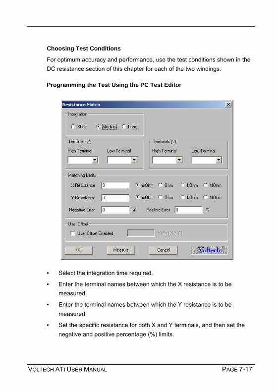
VOLTECH ATI USER MANUAL PAGE 7-17
Choosing Test Conditions
For optimum accuracy and performance, use the test conditions shown in the DC resistance section of this chapter for each of the two windings. Programming the Test Using the PC Test Editor
• Select the integration time required.
• Enter the terminal names between which the X resistance is to be measured.
• Enter the terminal names between which the Y resistance is to be measured.
• Set the specific resistance for both X and Y terminals, and then set the negative and positive percentage (%) limits.

TESTS AND TEST CONDITIONS
PAGE 7-18 VOLTECH ATI USER MANUAL
• If the "User Offset Enabled" check box is checked, a value can be entered into the edit box. The value entered (in the units shown) is then added to any results returned from the AT tester.
• Select OK. The test specification will now be displayed in the program window.
Use the PC Editor’s ‘Measure’ button (together with a sample part) if you are unsure of how to choose the test conditions.
Choosing Test Limits
The test limits are the specific resistances for both X and Y terminals together with + and percentage limits.
Use the PC Editor’s ‘Measure’ button (together with a sample part) if you are unsure of the resistance values.

VOLTECH ATI USER MANUAL PAGE 7-19
7.1.5 LS, LP – INDUCTANCE (SERIES AND PARALLEL EQUIVALENT
CIRCUIT)
Range Test voltage Test frequency Basic accuracy
1nH to 1MH 1mV to 5V 20Hz to 3MHz 0.05%
Inductance is the electrical parameter that is commonly used to check that a high-frequency transformer has been constructed according to its design and that it will operate properly in use. The inductance of a winding is determined by the number of turns and the construction and dimensions of the core materials; it may also vary with test conditions such as voltage and frequency.
The series and parallel inductance tests are used when testing signal, pulse, switched mode and similar transformers with ferrite type cores, where the inductance remains the same from small signals up to the operating conditions.
Faults in numbers of turns, core material and core gapping may be determined using this test.
For line frequency iron cored transformers where the inductance varies rapidly with voltage a magnetizing current test (MAGI) is recommended. (The MAGI test is only available on the Voltech AT3600).
AT Series Tester
Ls
Rs
Rp Lp

TESTS AND TEST CONDITIONS
PAGE 7-20 VOLTECH ATI USER MANUAL
Test Conditions
To measure inductance, the tester applies an AC voltage across the selected windings and measures the voltage across and the current through the winding. Using harmonic analysis, the measured voltage is divided by the current to obtain the complex impedance from which the inductance is extracted.
Generally, it is not necessary to measure the inductance at the normal operating conditions of the transformer, which could involve, for example, hundreds of volts. This is because the core material can normally be assumed to behave linearly in the operating region, and the inductance measured at a low level represents the inductance that will appear in use.
Also, it can usually be assumed that the inductance value does not vary significantly with frequency. Therefore, although high frequencies are available with the tester, measurement frequencies above a few hundred kilohertz should be used with caution. This is because the errors caused by the stray inductance and capacitance of your fixture may become much more significant at these frequencies. Compensation can be used to eliminate these errors.
Choosing the Test Signal
Wherever possible, the table below should be used for all inductance tests.
The inductance range should be chosen based on minimum value of inductance expected.
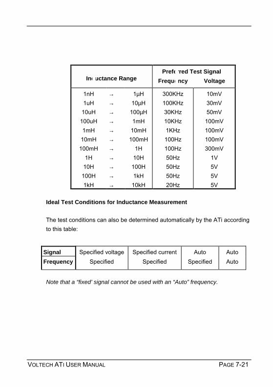
VOLTECH ATI USER MANUAL PAGE 7-21
Inductance Range
Preferred Test Signal Frequency Voltage
1nH 1uH
10uH 100uH 1mH
10mH 100mH
1H 10H
100H 1kH
→ → → → → → → → → → →
1µH 10µH
100µH 1mH
10mH 100mH
1H 10H
100H 1kH
10kH
300KHz 100KHz 30KHz 10KHz 1KHz 100Hz 100Hz 50Hz 50Hz 50Hz 20Hz
10mV 30mV 50mV
100mV 100mV 100mV 300mV
1V 5V 5V 5V
Ideal Test Conditions for Inductance Measurement The test conditions can also be determined automatically by the ATi according to this table:
Signal Specified voltage Specified current Auto Auto Frequency Specified Specified Specified Auto
Note that a “fixed’ signal cannot be used with an “Auto” frequency.

TESTS AND TEST CONDITIONS
PAGE 7-22 VOLTECH ATI USER MANUAL
Programming the Test Using the PC Test Editor
Choose the integration period (normally Medium) and enter the terminals to be measured.
Use the PC Editor’s ‘Measure’ button (together with a sample part) if you are unsure of how to choose the test conditions.

VOLTECH ATI USER MANUAL PAGE 7-23
Notes
When choosing test conditions, the following potential problems should be considered:
a) Current Levels
The upper voltage limits should be chosen to give a maximum current level of about 50mA rms for the lowest inductance expected. In some cases, this current may cause core saturation, and a lower voltage should be used. The minimum voltage level must be chosen so that the test current does not become so low that it cannot be sensibly measured. The lower voltage limits in the table above always give test currents higher than 3µA rms.
b) Self-resonant Frequency
At lower frequencies, the capacitance of the windings can normally be ignored because its impedance is much higher than that of the inductance. However, at very high frequencies, this is not so, the capacitance dominates and inductance cannot be measured. The self-resonant frequency of the transformer is the changeover point between these two regions.
Normally to get a good measurement of inductance, the test frequency should be less than 20% of the resonant frequency of the transformer.
In general high values of inductance will have a high inter-turn capacitance and hence a low resonant frequency. Where there is a choice of test frequencies always use the lower value, to minimise any problems due to self-resonance.
c) Non-linear Inductance
Normally inductance measurements should be used for transformers where the B-H characteristics are linear.
However, if inductance measurements are attempted for instance with line frequency transformers where the core material is non-linear even at low signal levels, the measured results can be highly dependant on the applied test signal.

TESTS AND TEST CONDITIONS
PAGE 7-24 VOLTECH ATI USER MANUAL
This can be a problem when trying to compare measurements made on commercially available impedance bridges, or component testers, with measurements made using the ATi. The test signal in such bridges is usually determined within the instrument, and is often at a fixed frequency and at a voltage level that is not guaranteed to be constant for all value of inductance.
Usually, if the actual test conditions of the bridge can be determined, and the tester is then programmed to deliver the same test conditions across the inductance the results will then agree. (See also the comments below on differences caused by the choice of equivalent circuit)
d) Equivalent Circuit
Inductance is always measured as part of a complex impedance, the result being expressed in terms of either a series or parallel equivalent circuit. Note that, for any given winding, the inductance values for the two circuits are not necessarily the same. This should be born in mind when specifying the test limits.
Choosing Test Limits
The test limits can be:
% A nominal value together with + and percentage limits.
>< Minimum and maximum values
> A minimum value only
< A maximum value only
Use the PC Editor’s ‘Measure’ button (together with a sample part) if you are unsure of the nominal value.
Remember to click on the units of limits (nH, mH etc.) when entering absolute values as limits.

VOLTECH ATI USER MANUAL PAGE 7-25
Test limits should be set as close as possible to detect assembly faults. A transformer made with a pair of gapped ferrite cores can often be tested to a tolerance of ±2%. For un-gapped cores, the tolerance may have to be as much as ±20% because of the cores manufacturing tolerance.
If the "User Offset Enabled" check box is checked, a value can be entered into the edit box. The value entered (in the units shown) is then added to any results returned from the AT tester.

TESTS AND TEST CONDITIONS
PAGE 7-26 VOLTECH ATI USER MANUAL
7.1.6 QL – QUALITY FACTOR
Measurement Range
Test Voltage
Test Frequency
Basic Accuracy
0.001 to 1000 1mV To 5V 20Hz To 3MHz 0.5%
When a transformer is energized, the changing magnetic field in the core causes two types of losses: hysteresis losses and eddy current losses. The total of these losses can be represented on the equivalent circuit of a transformer by a resistance associated with the inductance of the winding.
For this equivalent circuit the Quality Factor Q is defined as:
Q = ωωωωLs (where ωωωω = 2ππππf) Rs
For a given inductance, the lower the equivalent series resistance, the higher is the value of Q, i.e. the 'better' the coil.
Where Used
The Q factor test would normally be used for signal, pulse and switched mode power transformers, where the normal operating conditions require only small excursions of the B-H curve, never extending beyond the linear region.

VOLTECH ATI USER MANUAL PAGE 7-27
A Q Factor test will help to determine that the correct wires and cores have been correctly assembled for the part under test. Test Conditions
To measure Quality Factor, the tester applies an AC voltage across the selected winding, and measures the voltage across and the current through the winding. Using harmonic analysis, the measured voltage is divided by the current to obtain a complex impedance from which the Quality Factor is obtained. Choosing the Test Signal
For optimum accuracy and performance, use the test conditions chosen for inductance in the previous section of this chapter.
The test conditions can also be determined automatically by the ATi according to this table:
Note that a ‘fixed’ signal cannot be used with an ‘Auto’ frequency.
Signal Specified voltage Specified current Auto Frequency Specified Specified Specified

TESTS AND TEST CONDITIONS
PAGE 7-28 VOLTECH ATI USER MANUAL
Programming the Test Using the PC Test Editor
Choose the integration period (normally ‘medium’) and enter the terminal to be measured. Use the Editor’s ‘Measure’ button (together with a sample part) if you are unsure of how to choose the test conditions.
Choosing Test Limits
The test limits can be:
% A nominal value together with + and percentage limits.
>< Minimum and maximum values
> A minimum value only
< A maximum value only
Use the PC Editors Measure button (together with a sample part) if you are unsure of the nominal value.

VOLTECH ATI USER MANUAL PAGE 7-29
Typically, Q is tested against a minimum value. A typical ferrite cored transformer may have a Q >20. A specially designed low loss transformer may have a Q >100.
Because Q is a ratio of two impedances it has no units.
If the "User Offset Enabled" check box is checked, a value can be entered into the edit box. The value entered is then added to any results returned from the AT tester.

TESTS AND TEST CONDITIONS
PAGE 7-30 VOLTECH ATI USER MANUAL
7.1.7 D – DISSIPATION FACTOR OR TANδδδδ
Measurement Range
Test Voltage
Test Frequency
Basic Accuracy
0.001 to 1000 1mV to 5V 20Hz to 3MHz 0.5%
SEE ALSO THE CAPACITOR TESTING SECTION OF THIS CHAPTER.
The parameter ‘D’ is most often used as a measurement of the losses in a capacitor. It is analogous to Q for a transformer winding.
For this equivalent circuit the Dissipation Factor D is defined as: D = Rs (where ωωωω = 2ππππf) 1/ωωωωCs
For a given capacitance, the lower the equivalent series resistance, the lower is the value of the dissipation factor or tanδδδδ, i.e. the 'better' the capacitor.
Where Used
The dissipation factor test would normally be used for capacitors of all types. A D factor test will help to determine that the capacitor has been manufactured correctly.
AT SeriesTester
Rs
C

VOLTECH ATI USER MANUAL PAGE 7-31
Test Conditions
To measure Dissipation Factor, the tester applies an AC voltage across the selected winding, and measures the voltage across and the current through the winding. Using harmonic analysis, the measured voltage is divided by the current to obtain a complex impedance from which the Dissipation Factor is obtained.
Choosing the Test Signal
For optimum accuracy and performance, use the test conditions chosen for capacitance in a later section of this chapter.
The test conditions can also be determined automatically by the ATi according to this table:
Note that a fixed signal cannot be used with an Auto frequency.
Signal Specified voltage Specified current Auto Frequency Specified Specified Specified

TESTS AND TEST CONDITIONS
PAGE 7-32 VOLTECH ATI USER MANUAL
Programming the Test Using the PC Test Editor
Choose the integration period (normally ‘Medium’) and enter the terminals to be measured.
Use the Editor’s ‘Measure' button (together with a sample part) if you are unsure of the nominal value.
Choosing Test Limits
The test limits can be:
% A nominal value together with + and percentage limits.
>< Minimum and maximum values
> A minimum value only
< A maximum value only

VOLTECH ATI USER MANUAL PAGE 7-33
Use the PC Editors Measure button (together with a sample part) if you are unsure of the nominal value.
Typically, D is tested against a maximum value. A typical film dielectric capacitor may have a D < 0.01. Because D is a ratio of two impedances it has no units.
If the "User Offset Enabled" check box is checked, a value can be entered into the edit box. The value entered is then added to any results returned from the AT tester.
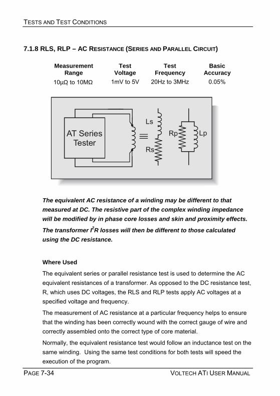
TESTS AND TEST CONDITIONS
PAGE 7-34 VOLTECH ATI USER MANUAL
7.1.8 RLS, RLP – AC RESISTANCE (SERIES AND PARALLEL CIRCUIT)
Measurement Range
Test Voltage
Test Frequency
Basic Accuracy
10µΩ to 10MΩ 1mV to 5V 20Hz to 3MHz 0.05%
The equivalent AC resistance of a winding may be different to that measured at DC. The resistive part of the complex winding impedance will be modified by in phase core losses and skin and proximity effects.
The transformer I2R losses will then be different to those calculated using the DC resistance.
Where Used
The equivalent series or parallel resistance test is used to determine the AC equivalent resistances of a transformer. As opposed to the DC resistance test, R, which uses DC voltages, the RLS and RLP tests apply AC voltages at a specified voltage and frequency.
The measurement of AC resistance at a particular frequency helps to ensure that the winding has been correctly wound with the correct gauge of wire and correctly assembled onto the correct type of core material.
Normally, the equivalent resistance test would follow an inductance test on the same winding. Using the same test conditions for both tests will speed the execution of the program.
AT SeriesTester
RpLs
Rs
Lp

VOLTECH ATI USER MANUAL PAGE 7-35
Test Conditions
To measure equivalent resistances, the AT applies an AC voltage across the selected winding, and measures the voltage across and the current through the winding. Using harmonic analysis, the measured voltage is divided by the current to obtain a complex impedance from which the equivalent series and parallel resistances are obtained.
Choosing the Test Signal
For optimum accuracy and performance, use the test conditions chosen for inductance in the previous section of this chapter.
The test conditions can also be determined automatically by the ATi according to this table:
Note that a ‘fixed’ signal cannot be used with an ‘Auto’ frequency.
Signal Specified voltage Specified current Auto Auto Frequency Specified Specified Specified Auto

TESTS AND TEST CONDITIONS
PAGE 7-36 VOLTECH ATI USER MANUAL
Programming the Test Using the PC Test Editor
Choose the integration period (normally ‘Medium’) and enter the terminals to be measured.
Use the PC Editor’s ‘Measure’ button (together with a sample part) if you are unsure of how to choose the test conditions.
Choosing Test Limits
The test limits can be:
% A nominal value together with + and percentage limits.
>< Minimum and maximum values
> A minimum value only
< A maximum value only
Use the PC Editor’s ‘Measure’ button (together with a sample part) if you are unsure of the nominal value.

VOLTECH ATI USER MANUAL PAGE 7-37
Remember to click on the units of limits (mOhm, Ohm etc.) when entering absolute values as limits.
Test limits should be set as close as possible to detect assembly faults.
If the "User Offset Enabled" check box is checked, a value can be entered into the edit box. The value entered is then added to any results returned from the AT tester.

TESTS AND TEST CONDITIONS
PAGE 7-38 VOLTECH ATI USER MANUAL
7.1.9 LSB, LPB – INDUCTANCE WITH BIAS (SERIES AND PARALLEL CIRCUIT)
DC Bias Measure Range
Test Voltage
Test Frequency
Basic Accuracy
1mA to 1A 1nH 1MH 1mV to 5V 20Hz to 3MHz 0.05%
Inductance is the electrical parameter that is commonly used to check that a high-frequency transformer has been constructed according to its design and that it will operate properly in use. As well as operating with AC signals, some transformers and chokes are designed to operate with a DC bias current flowing in a winding.
The inductance of a winding is determined by the number of turns and the construction and dimension of the core materials; it may also vary with test conditions such as voltage and frequency.
Where Used
The series and parallel inductance tests are used with DC bias when testing transformers with ferrite type cores that carry a significant DC bias current in normal operation. Such transformers and chokes are common in switched mode power conversion circuits.
Faults in numbers of turns, core material and core gapping may be determined using this test.
AT SeriesTester
RpLs
Rs
Lp

VOLTECH ATI USER MANUAL PAGE 7-39
For line frequency iron cored transformers where the inductance varies rapidly with voltage a magnetizing current test (MAGI) is recommended. This test is only available on the AT3600. See also the LS and LP tests for testing transformers where a DC bias current is not required.
Test Conditions
To measure inductance with DC bias, the tester first applies and stabilises the DC bias current and then applies an AC voltage across the selected winding. The tester measures the voltage across, and the current through, the winding.
Using harmonic analysis, the measured voltage is divided by the current to obtain the complex impedance from which the inductance is extracted.
Generally, it is not necessary to measure the inductance at the normal operating conditions of the transformer, which could involve, for example, hundreds of volts or several amps of bias. This is because the core material can normally be assumed to behave linearly in the operating region, and the inductance measured at a low level represents the inductance that will appear in use.
Choosing Test Conditions
For optimum accuracy and performance, use the test conditions chosen for inductance without bias in the previous section of this chapter.
The test conditions can also be determined automatically by the ATi according to this table:
Signal Specified voltage Specified current Auto Auto
Frequency Specified Specified Specified Auto
Bias Specified Specified Specified Specified
Note that a ‘fixed’ signal cannot be used with an ‘Auto’ frequency. The DC bias current level must always be specified.

TESTS AND TEST CONDITIONS
PAGE 7-40 VOLTECH ATI USER MANUAL
Programming the Test Using the PC Test Editor
Choose the integration period (normally Medium) and enter the terminals to be measured.
Do use the PC Editors Measure button (together with a sample part) if you are unsure of how to choose the test conditions.
Choosing Test Limits
The test limits can be:
% A nominal value together with + and percentage limits.
>< Minimum and maximum values
> A minimum value only
< A maximum value only

VOLTECH ATI USER MANUAL PAGE 7-41
Use Editor’s ‘Measure’ button (together with a sample part) if you are unsure of the nominal value.
Remember to click on the units of limits (nH, mH etc.) when entering absolute values as limits.
Test limits should be set as close as possible to detect assembly faults. A transformer made with a pair of gapped ferrite cores can often be tested to a
tolerance of ±2%. For un-gapped cores, the tolerance may have to be as much as ±20% because of the core manufacturers tolerance.
If the "User Offset Enabled" check box is checked, a value can be entered into the edit box. The value entered is then added to any results returned from the AT tester.

TESTS AND TEST CONDITIONS
PAGE 7-42 VOLTECH ATI USER MANUAL
7.1.10 L2 – INDUCTANCE MATCH
Measurement Range
Test Voltage
Test Frequency
Basic Accuracy
1:10000 to 10000:1 1mV to 5V 20Hz to 3MHz 0.1%
The inductance of a winding is determined by the number of turns and the construction and dimension of the core materials; it may also vary with test conditions such as voltage and frequency. See the LS and LP tests.
Windings consisting of the same number of turns and wound on the same core should have the same inductance value.
Where Used
The inductance match test as opposed to an ordinary inductance measurement (LS or LP) - is used on power conversion, audio and telecommunications transformers where it is important that the inductance of different pairs of windings is controlled and matched to a specified ratio. The absolute value of the inductances may be of less importance to the performance of the transformer than the match between two inductances.
Test Conditions
To measure inductance match, the tester makes two series inductance

VOLTECH ATI USER MANUAL PAGE 7-43
measurements (see the LS test) and compares the two results. Limits for the match of the two measured inductances may be set in terms of the ratio between them (e.g. 1:1 ±5%).
By adding further inductance match tests to the program any number of inductances can be tested for match. Choosing Test Conditions
For optimum accuracy and performance, use the test conditions shown in the inductance section of this chapter for each of the two windings. The frequency will be common to both windings being tested for match.
The test conditions can also be determined automatically by the ATi according to this table:
Signal Specified voltage Specified current Auto Auto Frequency Specified Specified Specified Auto
Note that a ‘fixed’ signal cannot be used with an ‘Auto’ frequency.

TESTS AND TEST CONDITIONS
PAGE 7-44 VOLTECH ATI USER MANUAL
Programming the Test Using the PC Test Editor
Choose the integration period (normally Medium) and enter the terminals to be measured.
Terminals (X) High and Low: Winding 1
Terminals (Y) High and Low: Winding 2
Use the PC Editor’s ‘Measure’ button (together with a sample part) if you are unsure of how to choose the test conditions.
Choosing the Test Limits
The test limits are a nominal value together with + and percentage limits.
Use the PC Editor’s ‘Measure’ button (together with a sample part) if you are unsure of the nominal value.
Test limits should be set as close as possible to detect assembly faults.
If the "User Offset Enabled" check box is checked, a value can be entered into the edit box. The value entered is then added to any results returned from the AT tester.

VOLTECH ATI USER MANUAL PAGE 7-45
7.1.11 LL, LLO – LEAKAGE INDUCTANCE AND LEAKAGE INDUCTANCE WITH
OFFSET
Measurement Range
Test Current
Test Frequency
Basic Accuracy
1nH to 1kH 20µA to 100mA 20Hz to 3MHz 0.1%
LLO Offset Range: 1H to +1H in 1nH steps
Due to imperfections in the coupling between windings, a short-circuited transformer acts as if there is inductive impedance in series with the winding. This impedance is known as the leakage inductance. Low leakage inductance implies good coupling; high leakage inductance, poor coupling.
Leakage inductance is important in many transformer designs such as switching power supply power transformers and electronic lighting ballasts.
The test is used to ensure that the windings and core have been positioned correctly.

TESTS AND TEST CONDITIONS
PAGE 7-46 VOLTECH ATI USER MANUAL
Test Conditions
Leakage inductance is tested by measuring the inductance of a primary winding when one or more secondary windings are shorted out. (See also the LS test). Typically, the impedance to be measured is very small, so a constant current AC test signal is used to provide stable, accurate results over a broad range of values.
The tester applies the short circuit automatically, without using any external switches or components.
By measuring and analysing the small voltage present across the short circuit, the tester compensates for the impedance of the wiring and other connections in the shorted path. The error due to the small short-circuit impedance can often be ignored. (This is the term ASC quoted in the accuracy specifications.)
When measuring on certain components, and particularly where the leakage inductance is below 1µH, it may not be possible for the AT to properly compensate for all parasitic effects. To confirm the accuracy of the LL test during program development, manually apply a good short circuit to the transformer and run a normal LS test. The best short-circuit will be a length of tinned copper wired (as short as possible) securely soldered directly across the secondary connections. If the result of this LS test is significantly different to the LL test (without the manual sort circuit but under the same test conditions) then use an LLO (leakage inductance with offset) test with an appropriate offset for production testing.
For example:
LL = 550 nH
LS = 500 nH (perfect short-circuit, same conditions)
Use an LLO test with -50nH offset.
Choosing the Test Signal
Choose a suitable test current and frequency based on the expected value of the leakage inductance using the following table:

VOLTECH ATI USER MANUAL PAGE 7-47
Leakage Inductance Range
Preferred Test Signal Frequency Current
100nH 1uH
10uH 100uH 1mH
10mH 100mH
1H
→ → → → → → → →
1uH 10uH
100uH 1mH
10mH 100mH
1H 10H
300kHz 100kHz 30kHz 10kHz 1kHz
100Hz 100Hz 50Hz
50mA 20mA 10mA 5mA 5mA 5mA 1mA
500µA
The test conditions can also be determined automatically by the ATi according to this table:
Note that a ‘fixed’ signal cannot be used with an ‘Auto’ frequency.
Signal Specified voltage Specified current Auto Auto Frequency Specified Specified Specified Auto

TESTS AND TEST CONDITIONS
PAGE 7-48 VOLTECH ATI USER MANUAL
Programming the Test Using the PC Test Editor
Choose the integration period (normally Medium) and enter the terminals to be measured. The Primary Terminals are where the test signal will be applied; the Secondary Terminals will be short-circuited together.
Note that more than one secondary can be short-circuited at the same time by adding more of the available terminals to the used section of the dialogue.
NOTE: Because leakage inductance is measured with a secondary winding shorted out, be careful to choose a test signal that will not cause excessive currents to flow. This is particularly significant in transformers where the turns ratio is very high and the shorted winding has only a few turns.
If, for example, the primary winding has 300 turns, and the secondary 3 turns, a test current of 10mA flowing through the leakage inductance on the primary side will give rise to a current of 1 Amp flowing in the shorted secondary winding.

VOLTECH ATI USER MANUAL PAGE 7-49
In order to protect transformer windings, the test current when measuring leakage inductance is limited in the table to 50mA maximum.
In addition, the problem of self-resonant frequency listed under the primary inductance test also applies when measuring leakage inductance, so always use the lower of the available band of frequencies.
Use the Editor’s ‘Measure’ button (together with a sample part) if you are unsure of how to choose the test conditions.
Choosing Test Limits
The test limits can be:
% A nominal value together with + and percentage limits.
>< Minimum and maximum values
> A minimum value only
< A maximum value only
Use the PC Editor’s ‘Measure’ button (together with a sample part) if you are unsure of the nominal value.
Remember to click on the units of limits (nH, mH etc.) when entering absolute values as limits.
Note that more than one secondary can be short-circuited at the same time by adding more of the available terminals to the used section of the dialogue.
If the "User Offset Enabled" check box is checked, a value can be entered into the edit box. The value entered is then added to any results returned from the AT tester.
Normally a user offset would not be required. However for small values of leakage inductance (<1µH) when there are a number of additional low terminals, it is not always possible during fixture compensation for the tester to remove all of the parasitic errors of the test fixture. In this case, the user offset may be required to fully remove the errors. The User Offset provides this additional feature. See also the notes under 'test conditions' above.
Choose test limits as close as possible to the nominal value in order to detect faults. It is common practice to specify a maximum limit only.

TESTS AND TEST CONDITIONS
PAGE 7-50 VOLTECH ATI USER MANUAL
7.1.12 C – INTERWINDING CAPACITANCE TEST (PARALLEL CIRCUIT)
Measurement Range
Test Voltage
Test Frequency
Basic Accuracy
100fF to 1mF 1mV to 5V 20Hz to 3MHz 0.1%
SEE ALSO THE CS AND CP TESTS AND THE CAPACITOR TESTING
SECTION OF THIS CHAPTER.
Capacitance occurs in transformers due to the physical proximity of, and electrostatic coupling between, different turns of wire.
In general, the capacitance is distributed between different layers within a winding, and between the outside layer of one winding and the inside layer of the next. Although the capacitance is distributed across windings, it is usually represented by a simple equivalent circuit showing a single capacitance from one winding to the next.
Where Used
An interwinding capacitance test can be used to check for correct winding position and to check for the correct insulation thickness between windings where isolation between primary and secondary windings is important.
The test can be used to check for capacitance between windings where, for example, too large a capacitance may couple unwanted noise signals between power and control circuits.

VOLTECH ATI USER MANUAL PAGE 7-51
Test Conditions
To measure capacitance, the tester applies an AC voltage between the windings to be tested, usually with all taps on each winding shorted together. It then measures the voltage between the windings, and the resulting current. Dividing the voltage by the current gives the interwinding impedance, from which the capacitance is extracted using harmonic analyses.
Capacitance is measured as part of a complex impedance. The AT Series C test uses a parallel equivalent circuit for capacitance measurements. CS series circuit capacitance is also available.
Choosing the Test Signal
Recommended test conditions for different values of capacitance:
Capacitance Range Preferred Test Signal Frequency Voltage
1pF 10pF
100pF 1nF
10nF 100nF
→ → → → → →
10pF 100pF
1nF 10nF
100nF 10µF
100KHz 100KHz 10KHz 1KHz 100Hz 100Hz
5V 5V 5V 5V 5V
500mV
Test Conditions for Capacitance Measurement
The test conditions can also be determined automatically by the ATi according to this table:
Voltage Specified Auto Auto Frequency Specified Specified Auto
Note that a ‘fixed’ voltage signal cannot be used with an ‘Auto’ frequency.

TESTS AND TEST CONDITIONS
PAGE 7-52 VOLTECH ATI USER MANUAL
Programming the Test Using the PC Test Editor
Choose the integration period (normally Medium) and enter the terminals to be measured. More than one terminal can be High and more than one terminal can be Low. This is to allow testing of the complete primary to secondary capacitance of a transformer by taking all primary terminals High and all secondary terminals Low.

VOLTECH ATI USER MANUAL PAGE 7-53
When choosing the test conditions, the following potential problems should be considered:
a) Current Levels
For larger capacitance, particularly at higher frequencies, the current flowing during the measurement can be very high, and similarly the measured current could also be very small for small capacitance at lower frequencies and voltages.
Where possible, you should use the recommended test signal levels in the table above to ensure that the currents, which flow, can be measured accurately. b) Non-linear Capacitance
Normally non-linearities in the stray capacitance of transformers are not a problem, and therefore capacitance is measured with as large a voltage as possible. c) Equivalent Circuit
As with inductance, capacitance is actually measured as a complex impedance, and therefore the result can be expressed in terms of either a series or a parallel equivalent circuit.
See the 'Series and Parallel Circuits' and 'Capacitor Measurements' sections at the end of this chapter.
The tester always uses a parallel equivalent circuit for inter-winding capacitance measurements. Series and parallel capacitance tests (CS and CP) are also available.
Use the PC Editor’s ‘Measure’ button (together with a sample part) if you are unsure of how to choose the test conditions. Choosing Test Limits
The test limits can be:
% A nominal value together with + and percentage limits.
>< Minimum and maximum values

TESTS AND TEST CONDITIONS
PAGE 7-54 VOLTECH ATI USER MANUAL
> A minimum value only
< A maximum value only
Use the PC Editor’s ‘Measure’ button (together with a sample part) if you are unsure of the nominal value.
Remember to click on the units of limits (pF, nF etc.) when entering absolute values as limits.
Test limits should be set as close as possible to the nominal value in order to detect faults. A typical tolerance would be ± 20%.
If the "User Offset Enabled" check box is checked, a value can be entered into the edit box. The value entered is then added to any results returned from the AT tester.

VOLTECH ATI USER MANUAL PAGE 7-55
7.1.13 CS AND CP – CAPACITANCE TEST (SERIES AND PARALLEL
CIRCUIT)
Measurement Range
Test Voltage
Test Frequency
Basic Accuracy
100fF to 1mF 1mV to 5V 20Hz to 3MHz 0.1%
SEE ALSO THE C TEST AND THE CAPACITOR TESTING SECTION OF
THIS CHAPTER.
The CS and CP tests can be used to measure the capacitance of a wide range of components up to 1 milli-farad.
Test Conditions
To measure capacitance, the tester applies an AC voltage across the designated terminals. It then measures the voltage and the resulting current. Dividing the voltage by the current gives the complex impedance, from which the capacitance is extracted using harmonic analyses.
Choosing the Test Signal
Recommended test conditions for different values of capacitance are the same as for the C test.
AT SeriesTester
CPC
RLPRLS
CS

TESTS AND TEST CONDITIONS
PAGE 7-56 VOLTECH ATI USER MANUAL
Test Conditions for Capacitance Measurement
The test conditions can also be determined automatically by the ATi according to this table:
Voltage Specified Auto Auto Frequency Specified Specified Auto
Note that a ‘fixed’ voltage signal cannot be used with an ‘Auto’ frequency. CS and CP are currently only available on the Atis front panel LCR mode. Contact your local supplier or check the Voltech website at www.voltech.com for up to date information.

VOLTECH ATI USER MANUAL PAGE 7-57
7.1.14 C2 – CAPACITANCE MATCH
Measurement Range
Test Voltage
Test Frequency
Basic Accuracy
1:1000 to 1000:1 1mV to 5V 20Hz to 3MHz 0.2%
Capacitance occurs in transformers due to the physical proximity of, and electrostatic coupling between, different turns of wire.
In general, the capacitance is distributed between different layers within a winding, and between the outside layer of one winding and the inside layer of the next. Although the capacitance is distributed, it is usually represented by a simple equivalent circuit showing a single capacitance from one winding to the next.
Where Used
The capacitance match test as opposed to an ordinary capacitance measurement (C) - is used on power conversion, audio and telecommunications transformers where it is important that the capacitance between different pairs of windings is controlled and matched. Mismatched capacitances may couple unwanted noise signals from one winding to another or ground. The test will determine if one winding has been placed incorrectly or if the wrong thickness of insulation has been used.

TESTS AND TEST CONDITIONS
PAGE 7-58 VOLTECH ATI USER MANUAL
Test Conditions
To measure capacitance match, the tester makes two capacitance measurements (see the C test) and compares the two results. Limits for the match of the two measured capacitances may be set in terms of the ratio between them (e.g. 1:1 ±5%).
By adding further capacitance match tests to the program any number of inter-winding capacitances can be tested for match.
The AT Series Testers use a parallel equivalent circuit for capacitance match measurements.
Programming the Test Using the PC Test Editor
Choose the integration period (normally Medium).

VOLTECH ATI USER MANUAL PAGE 7-59
To enter the capacitor terminals into the Editor C2 test dialogue box, add the terminals for the first capacitor X into the High and Low areas. For example if the capacitance is between terminals A and B, add A to the High Terminals (X) Used area and B to the Low Terminals (X) Used area.
Then click on the Terminals (Y) button and add the High and Low terminals for the second capacitance.
Choosing Test Conditions
For optimum accuracy and performance choose test conditions based on the nominal value of capacitance as listed in the previous capacitance section.
The test conditions can also be determined automatically by the ATi according to this table:
Voltage Specified Auto Auto Frequency Specified Specified Auto
Note that a ‘fixed’ voltage signal cannot be used with an ‘Auto’ frequency.
Use the Editor’s ‘Measure’ button (together with a sample part) if you are unsure of how to choose the test conditions.
See also the notes relating to choosing tests conditions for capacitance in the previous section.
Choosing Test Limits
The test limits are entered as a + and percentage around a nominal ratio.
Use the PC Editors Measure button (together with a sample part) if you are unsure of the nominal value.
If the "User Offset Enabled" check box is checked, a value can be entered into the edit box. The value entered is then added to any results returned from the AT tester.

TESTS AND TEST CONDITIONS
PAGE 7-60 VOLTECH ATI USER MANUAL
7.1.15 TR – TURNS RATIO AND PHASING
Measurement Range
Test Voltage
Test Frequency
Basic Accuracy
1:100,000 100,000:1 1mV to 5V 20Hz to 3MHz 0.1%
Applying an AC voltage to the primary of the transformer will produce an AC voltage in the secondary. Turns ratio describes the voltage ratio of the measured voltages from one winding and another.
The secondary voltage may be in phase with the primary voltage or it may be anti-phase depending on the winding and the termination of the windings.
Where Used
The turns ratio test is used to confirm that windings have the correct ratio of turns between them, and that the phasing of the windings is correct. This test is the preferred test for signal, pulse and switched mode power transformers where the normal operating conditions require only small excursions of the B-H curve, never extending beyond the linear region. See also the test TRL turns ratio by inductance.

VOLTECH ATI USER MANUAL PAGE 7-61
Test Conditions
To measure turns ratio, the test signal is applied to one winding called the energized winding. The voltages across two other windings (one of which may be the energized winding) are measured. The turns ratio is then measured by dividing one measured voltage by the other, and making a compensation for the effects of winding resistance.
It is recommended that you choose the winding with the highest number of turns as the one to be energized. A possible exception to this rule is when you wish to measure the ratio between two windings that should be accurately matched at 1:1. In this case it may be better to energize a third winding with a lower number of turns, to ensure that any measurement errors apply equally to the two windings under test.
Choosing Test Conditions
The recommended test conditions depend on the inductance of the energized winding; they are given in the table below assuming that the energized winding is the one with the highest number of turns:
Inductance of the
Energized Winding Preferred Test Signal
Frequency Voltage
100nH 1uH
10uH 100uH 1mH
10mH 100mH
1H 10H
100H 1kH
→ → → → → → → → → → →
1µH 10µH
100µH 1mH
10mH 100mH
1H 10H
100H 1kH
10kH
300kHz 100kHz 30kHz 10kHz 1kHz
100Hz 100Hz 50Hz 50Hz 50Hz 20Hz
10mV 30mV 50mV
100mV 100mV 100mV 300mV
1V 5V 5V 5V

TESTS AND TEST CONDITIONS
PAGE 7-62 VOLTECH ATI USER MANUAL
The test conditions can also be determined automatically by the ATi according to this table: Voltage Specified Auto Auto Frequency Specified Specified Auto Note that a ‘fixed’ voltage signal cannot be used with an ‘Auto’ frequency.
Programming the Test Using the PC Test Editor
Choose the integration period (normally Medium).
Energized Terminals: The terminals where the test signal will be applied. This is normally the winding with the greatest number of turns.

VOLTECH ATI USER MANUAL PAGE 7-63
Primary Terminals High and Low: The zero phase reference terminals, which are often the same as the energized terminals.
Secondary Terminals High and Low: The turns ratio and polarity measurement will be made between the primary and secondary terminals.
Use the PC Editor’s ‘Measure’ button (together with a sample part) if you are unsure of how to choose the test conditions.
Notes: The signal is applied to the primary winding, or the winding that has the largest number of turns.
However, if by doing this, the expected voltage on the winding with the smallest number of turns falls below 1mV, then the test voltage should be increased.
This may also require an increase in the test frequency so that the current taken by the driven winding does not become too large, but in general this frequency increase should be kept as small as possible to avoid problems caused by stray capacitance at high frequencies.
Where Matching in Groups Is Important
In some transformer designs, the turns ratio between a primary winding and a secondary winding is not as important as the ratio between different primaries or different secondaries.
To make the most accurate measurements in such cases apply the test signal to the primary winding and measure the turns-ratio from primary to one of the secondaries.
Then, leaving the primary energized as above, measure the turns ratio between the secondaries.
Next, energize a secondary winding (possibly at a different voltage and / or frequency depending on its inductance) and measure the turns ratio between the various primaries.

TESTS AND TEST CONDITIONS
PAGE 7-64 VOLTECH ATI USER MANUAL
In this way windings that should be matched are treated equally during the test.

VOLTECH ATI USER MANUAL PAGE 7-65
Choosing Test Limits
The limits may be entered as:
1. A nominal value together with a percentage tolerance (%)
Enter the nominal Primary to Secondary ratio, together with the limits as positive and negative percentage values.
2. An absolute number of turns (#)
When limits are set as +/- an absolute number of turns, the tester converts these limits to the % type in the following way:
= +/- (Pri Limit + Sec Limit ) x 100%
(Pri Turns Sec Turns )
(You can see the exact result of this conversion by clicking on % limits in the Editor dialogue once the absolute, #, limits have bee entered.)
For example, take a typical Switched Mode Power Supply transformer with windings in the ratio of 200:10.
Typically, a prior measurement of inductance will have confirmed the correct number of primary turns have been fitted with the correct cores. Setting absolute limits of 0 on the primary and 1 on the secondary will result in limits of:
Nominal Ratio: 200/10 =20
Ratio + 1 sec turn =18.18
Ratio 1 sec turn = 22.22
Limits calculated by tester = (0/200 + 1/10) x 100%= +/- 10%
The equivalent ratio limits used by tester are:
Upper limit = 22. Lower Limit = 18

TESTS AND TEST CONDITIONS
PAGE 7-66 VOLTECH ATI USER MANUAL
Which equates to the actual ratios with a one-turn error on the secondary.
In general, the voltages obtained during any voltage turns ratio test will not equate exactly to the theoretical calculation of Np / Ns, because, for example, of the relative positions of the windings with respect to each other and the core.
General Rule
When setting turns ratio limits in absolute terms, use a limit of ½ turn less than the number of turns you want to detect. In this case, set a limit of 0 (pri) and ½ (sec). This will result in equivalent limits of 19 and 21. Ideal for detecting errors of one turn or more.
What happens if I set absolute limits for both primary and secondary windings?
If you want to detect up to a ten-turn error on the primary and one-turn on the secondary, in the above example, set 9½ (pri) and ½ (sec). The tester uses the equivalent ratio limits: 21.95 and 18.05. Setting both limits WIDENS the limit to allow for an error of ten turns on the primary SIMULTANEOUSLY with one turn on the secondary.
I.e., to allow 190:11 (17.27) and 210:9 (23.33).
Notice that these limits will NOT detect just a one-turn error on the secondary because you have now chosen limits to allow for errors on both primary and secondary, resulting in a broader tolerance on the absolute ratio.

VOLTECH ATI USER MANUAL PAGE 7-67
How do I set limits that will detect a one-turn error on either the primary or the secondary?
To do this you must set limits that will detect the smallest possible error. This will be due to the one-turn error being on the winding with the largest number of turns.
In the above example then, set absolute limits of ½ turn (pri) and 0 turn (sec). (Remember to use the n-½ rule).
The equivalent limits used by the tester will be:
20.05 and 19.95
This will certainly detect a one-turn error in the primary, but because of the physical errors already described, these limits may be too severe for a normal good part. This is why a combination of inductance and turns ratio tests are normally used to confirm the correct assembly of transformers.
The polarity test may be selected as (+)ve, (-)ve or no test. To measure the exact interwinding phase angle use the PHAS test.
Use the PC Editor’s ‘Measure’ button (together with a sample part) if you are unsure of the nominal value.
If the "User Offset Enabled" check box is checked, a value can be entered into the edit box. The value entered is then added to any results returned from the AT tester.

TESTS AND TEST CONDITIONS
PAGE 7-68 VOLTECH ATI USER MANUAL
7.1.16 TRL – TURNS RATIO BY INDUCTANCE
Measurement Range
Test Voltage
Test Frequency
Basic Accuracy
1:100 100:1 1mV to 5V 20Hz to 3MHz 0.1%
The correct ratio of the number of turns on one winding to the number of turns on another winding is important for the proper operation of any transformer.
The turns ratio is often determined by calculating the ratio of the voltages produced across the windings (the TR test), but it can also be determined from a measurement of the two winding inductances.
The inductance of a winding is proportional to the number of turns squared:
L ∝∝∝∝ N 2
and the turns ratio can thus be calculated as the square root of the inductance ratio.

VOLTECH ATI USER MANUAL PAGE 7-69
Where Used
The turns ratio by inductance test is used on transformers that have poor coupling btween windings and where a turns ratio by voltage (TR) test may not produce the expected result.
For example, transformers for electronic lighting ballasts are often deliberately wound to have relatively large values of leakage inductance. During voltage TR testing, some of the voltage will appear across the leakage inductance and alter the result.
The TRL test is not affected by leakage inductance and other parasitic components in this way.
Test Conditions
To measure turns ratio by inductance, two inductance measurements are made - one on each winding. The same voltage (at the specified amplitude and frequency) is applied to each winding in turn and the inductance of each is determined from the measured voltage and current using harmonic analysis. The turns ratio is then calculated as the square root of the ratio of the inductances.
The inductance of a winding can often depend upon the flux density in the core/windings. Since the flux density will depend upon the signal energising the winding, it is important that both windings are energized at the same level. This will ensure that both inductances are measured along the same region of the B/H curve of the core and give a true ratio.
Choosing Test Conditions
The simplest method of setting the test conditions is to use the Measure button of the PC Editor software. There are two other methods of inputting the test parameters, one is to set the primary voltage and frequency and let the editor set the secondary voltage, and the second is to set both voltages manually.

TESTS AND TEST CONDITIONS
PAGE 7-70 VOLTECH ATI USER MANUAL
Programming the Test Using the PC Test Editor
Using the Measure Button to Set Test Parameters
Select the integration period you require, enter the primary and secondary terminals, then click on the Measure button as explained in the Editor section of this manual. The Editor will then enter the test signal and show the measured turns ratio. Set percentage limits on this ratio and click OK (you may select a polarity test before clicking OK).
Using the Auto Button to Set Secondary Voltage
To do this you must know the primary inductance.
Select the test voltage and frequency for the primary from the table below and enter them in the TRL dialogue box. Enter the turns ratio, then press the Auto button next to the secondary voltage parameter, the tester will automatically select the appropriate test voltage for the secondary winding when the program is running.

VOLTECH ATI USER MANUAL PAGE 7-71
Where: Lm = Intermediate inductance Lp = Primary inductance Ls = Secondary inductance Vp = Primary voltage Vs = Secondary voltage Vm = Intermediate voltage Np = Primary turns Ns = Secondary turns
Setting the Primary and Secondary Parameters Manually
To do this you will need to know the inductance of the primary and secondary windings.
The optimum test conditions are chosen for an inductance value that is between the primary and secondary (Lm).
Look up the recommended test signal for this inductance.
Enter the recommended frequency for this inductance as the test frequency.
The primary and secondary voltages can be calculated from the following:
If you calculate Vs or Vp to be greater than 5V, you should set 5V as your test signal. If you calculate Vs or Vp to be less than 1mV, you should set 1mV as your test signal.
spm LLL ×=
s
pmp
NNVV =
p
sms
NNVV =

TESTS AND TEST CONDITIONS
PAGE 7-72 VOLTECH ATI USER MANUAL
Choosing the Test Conditions Based on Vm
Intermediate Inductance
(Lm)
Preferred Test Signal
Frequency Voltage (Vm)
100nH 1uH
10uH 100uH 1mH
10mH 100mH
1H 10H
100H 1KH
→ → → → → → → → → → →
1uH 10uH
100uH 1mH
10mH 100mH
1H 10H
100H 1KH
10KH
300KHz 100KHz 30KHz 10KHz 1KHz 100Hz 100Hz 50Hz 50Hz 50Hz 20Hz
10mV 30mV 50mV
100mV 100mV 100mV 300mV
1V 5V 5V 5V
The ATi can automatically determine the test conditions according to the following table:
Voltage Specified Auto Auto Frequency Specified Specified Auto
Note that a ‘fixed’ voltage signal cannot be used with an ‘Auto’ frequency.
Choosing Test Limits
When specifying turns ratio tests, it is preferable to avoid limits which are unnecessarily tight, and which may therefore lead to measurement difficulties.
For example, if two equal secondary windings should have 10 turns each, the ratio should be 1:1. One turn in error would produce a ratio error of 10% or -10% (i.e. 11:10 or 10:11), and therefore limits of +5% and -5% would be suitable to detect the error.

VOLTECH ATI USER MANUAL PAGE 7-73
7.1.17 LVOC – LOW VOLTAGE OPEN CIRCUIT
Measurement Range
Test Voltage
Test Frequency
Basic Accuracy
100µV to 5V 1mV to 5V 20Hz to 3MHz 0.1%
Applying an AC voltage to the primary of the transformer will produce an AC voltage in the secondary. Low Voltage Open Circuit measures the ‘open circuit’ voltage produced when the specified test signal is applied.
The secondary voltage may be in phase with the primary voltage or it may be anti-phase depending on the winding and the termination of the windings.
Where Used
The low voltage open circuit test is used to confirm that windings have the correct ratio of turns between them, and that the phasing of the windings is correct. This test is used for signal, pulse and switched mode power transformers where the normal operating conditions require only small excursions of the B-H curve, never extending beyond the linear region. On the AT3600 only, a high voltage open circuit test is available for testing line

TESTS AND TEST CONDITIONS
PAGE 7-74 VOLTECH ATI USER MANUAL
frequency transformers at their operating point (up to 270V, 1kHz and 2A). See also the test TR turns ratio.
Test Conditions
To measure low voltage open circuit, the test signal is applied to one winding called the energized winding. The voltages across another winding (or the same, energized winding) are measured. The low voltage open circuit measurement is the rms value of the voltage measured and can be an AC or a DC voltage.
It is recommended that you choose the winding with the highest number of turns as the one to be energized.
Choosing Test Conditions
The recommended test conditions depend on the inductance of the energized winding; they are given in the table below assuming that the energized winding is the one with the highest number of turns:
Inductance of the
Energized Winding Preferred Test Signal
Frequency Voltage
100nH 1uH
10uH 100uH 1mH
10mH 100mH
1H 10H
100H 1kH
→ → → → → → → → → → →
1µH 10µH
100µH 1mH
10mH 100mH
1H 10H
100H 1kH
10kH
300kHz 100kHz 30kHz 10kHz 1kHz
100Hz 100Hz 50Hz 50Hz 50Hz 20Hz
10mV 30mV 50mV
100mV 100mV 100mV 300mV
1V 5V 5V 5V
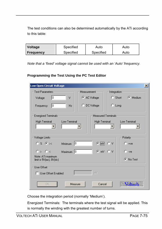
VOLTECH ATI USER MANUAL PAGE 7-75
The test conditions can also be determined automatically by the ATi according to this table:
Voltage Specified Auto Auto Frequency Specified Specified Auto Note that a ‘fixed’ voltage signal cannot be used with an ‘Auto’ frequency.
Programming the Test Using the PC Test Editor
Choose the integration period (normally Medium).
Energized Terminals: The terminals where the test signal will be applied. This is normally the winding with the greatest number of turns.

TESTS AND TEST CONDITIONS
PAGE 7-76 VOLTECH ATI USER MANUAL
Primary Terminals High and Low: The zero phase reference terminals that are often the same as the energized terminals.
Secondary Terminals High and Low: The turns ratio and polarity measurement will be made between the primary and secondary terminals.
Use the PC Editor’s ‘Measure’ button (together with a sample part) if you are unsure of how to choose the test conditions.
Choosing Test Limits
The test limits can be:
% A nominal value together with + and percentage limits.
>< Minimum and maximum values
> A minimum value only
< A maximum value only
Use the Editor’s ‘Measure’ button (together with a sample part) if you are unsure of the nominal value.
Remember to click on the units of limits (mV or V) when entering absolute values as limits.
Test limits should be set as close as possible to the nominal value in order to detect faults. A typical tolerance would be ± 5%.
If the "User Offset Enabled" check box is checked, a value can be entered into the edit box. The value entered is then added to any results returned from the AT tester.

VOLTECH ATI USER MANUAL PAGE 7-77
7.1.18 IR – INSULATION RESISTANCE
Test Measurement Range
Test Voltage
Test Frequency
Basic Accuracy
IR 1MΩ to 1GΩ 100V to 500V DC 1.0%
Transformer windings are often insulated from each other and from the core by insulating tape, enamel on the wire or by plastic moulding on the bobbin.
The 'quality' of the insulation can be assessed by applying a DC voltage across the insulation and measuring the resistance. The voltage applied is usually greater than the voltage that the insulation will see in normal use.
Where Used
An Insulation Resistance check is recommended as good practice for most transformers to check the integrity of the insulation between separate windings, or between a windings, or between a winding and a screen.
Test Conditions

TESTS AND TEST CONDITIONS
PAGE 7-78 VOLTECH ATI USER MANUAL
To measure insulation resistance, the tester applies a DC voltage between two groups of windings with the windings in each group being shorted together. Each group may contain as many windings as you wish.
The voltage and current are measured; dividing the voltage by the current gives the insulation resistance.
Choosing Test Conditions
The voltage should normally be set to just greater than twice the peak working voltage of the winding.
Programming the Test Using the PC Test Editor
Choose the integration period (normally Medium) and enter the terminals to be measured. More than one terminal can be High and more than one

VOLTECH ATI USER MANUAL PAGE 7-79
terminal can be Low. This is to allow testing, for example, of the complete primary to secondary insulation resistance of a transformer by taking all primary terminals High and all secondary terminals Low.
Note that the Editor’s ‘Measure’ button CANNOT be used to determine the test voltage.
Choosing Test Limits
Although the tester is capable of measuring insulation resistance values greater than 1GΩ, there is no need to specify so high a value to check that windings are isolated.
In many cases, specifying a lower value will speed up the execution of the test. A value of 100MΩ is generally suitable for most applications.
Where higher voltage safety testing is required, see the Hi-Pot tests that are available with the Voltech AT3600.
If the "User Offset Enabled" check box is checked, a value can be entered into the edit box. The value entered is then added to any results returned from the AT tester.

TESTS AND TEST CONDITIONS
PAGE 7-80 VOLTECH ATI USER MANUAL
7.1.19 GBAL – GENERAL LONGITUDINAL BALANCE
Measurement Range
Test Voltage
Test Frequency
Basic Accuracy
0 dB to 100 dB 1mV to 5V 20Hz to 3MHz 0.5dB
Longitudinal balance is a measure of the common mode rejection ratio (CMRR) of a transformer. That is, the ability of the transformer to reject unwanted noise signals that are common to both input terminals with respect to a common point.
An ideal transformer would have infinite CMRR (Vout1 = 0). In practice differences in symmetry of transformer construction mean that input common mode signals appear as unwanted output voltages.
See also the LBAL test.
Where Used
The general longitudinal balance test as opposed to the standard longitudinal balance test, LBAL - is used to confirm the longitudinal balance (or CMRR) of

VOLTECH ATI USER MANUAL PAGE 7-81
audio and telecommunications transformers to the standards IEEE455 and FCC 68.310 and wherever similar connection methods are specified.
Test Conditions
The source and load resistors (RS and RL) and the measuring transformer are connected to the transformer under test as shown. This may be done automatically using the testers OUT test.
The voltages Vout1 and Vout2 are measured whilst Vin is held constant. The ratio of these two voltages reflects the transformer under tests ability to reject common mode voltages.
General Longitudinal balance is calculated as the ratio:
GBAL = 20 log (Vout2 / Vout1)
IEEE 455 Method (Used in Canada, Europe and ROW)
Energized (Vin) Measured (Vout) Hi Lo Hi Lo
Terminals (X) A+B C A C
Terminals (Y) A+B C D E
Fixture Transformer
VIN VOUT1
C
E
D
B
A
RS
RS RL
VOUT2

TESTS AND TEST CONDITIONS
PAGE 7-82 VOLTECH ATI USER MANUAL
FCC 68.310 Method (Used in USA)
Energized (Vin) Measured (Vout) Hi Lo Hi Lo
Terminals (X) A B C D
Terminals (Y) A B E F
Choosing Test Conditions
The source and load resistors and the fixture transformer for the IEEE and FCC methods are assumed to be on the fixture, but are not shown on the Editor schematic. They are switched in circuit using an OUT test that must be inserted in the program before the GBAL test. (The relay patterns associated with inserting and removing fixture resistors have deliberately not been included in the GBAL test dialogue for two reasons: a) it would make the dialogue too complicated, and b) it is not always necessary, e.g. in the case of a fixture where the resistors are permanently fitted in circuit).
RL
Fixture Transformer
A
B D
VOUT2
VOUT1
C
VIN
F
E

VOLTECH ATI USER MANUAL PAGE 7-83
Programming the Test Using the PC Test Editor
The voltage and frequency are usually determined by the final application of the part under test.
Select the integration period, which is normally Medium
Enter the required terminal names:
Terminals (X) - the energized winding.
Terminals (X) the measured voltage VOUT1
Terminals (Y) the energized winding (normally the same as the Terminals (X) energized winding)
Terminals (Y) the measured voltage VOUT2
The measurement can be compensated for any scaling on the fixture. For example where the fixture transformer is not 1:1.
Note that the Editor’s ‘Measure’ button CANNOT be used to determine the test voltage.

TESTS AND TEST CONDITIONS
PAGE 7-84 VOLTECH ATI USER MANUAL
Choosing Test Limits
The test limits can be:
% A nominal value together with + and percentage limits.
>< Minimum and maximum values
> A minimum value only
< A maximum value only
Use the PC Editors Measure button (together with a sample part) if you are unsure of the nominal value.

VOLTECH ATI USER MANUAL PAGE 7-85
7.1.20 LBAL – LONGITUDINAL BALANCE
Measurement Range
Test Voltage
Test Frequency
Basic Accuracy
0 dB to 100 dB 1mV to 5V 20Hz to 3MHz 0.5dB
Longitudinal balance is a measure of the common mode rejection ratio (CMRR) of a transformer. That is, the ability of the transformer to reject unwanted noise signals that are common to both input terminals with respect to a common point.
An ideal transformer would have infinite CMRR (Vout1 = 0). In practice differences in symmetry of transformer construction mean that input common mode signals appear as unwanted output voltages.
See also the GBAL test.
Where Used
The longitudinal balance test is used to confirm the CMRR of audio and telecommunications transformers that are designed to be connected to a balanced line. The test ensures that the transformer will reject common mode noise signals as required in use. Faults in the placement of windings or core may be detected using this test.

TESTS AND TEST CONDITIONS
PAGE 7-86 VOLTECH ATI USER MANUAL
Test Conditions
The source and load resistors (RS and RL) are connected to the transformer - this may be done automatically using the testers OUT test. Then, two measurements are performed using the circuits above, which the tester automatically configures. First the test voltage Vin is applied as a common mode signal and the output voltage Vout1 is recorded, and then the same Vin is applied as a normal input voltage and the output Vout2 is recorded.
Longitudinal balance is calculated as the ratio:
LBAL = 20 log10 (Vout2 / Vout1)
Energized (Vin) Measured (Vout) Hi Lo Hi Lo
Terminals (X) A B D E
Terminals (Y) A+B C D E
VOUT2
C
E
D
B
A
E
D
B
A
RS
RS VIN1 RL VOUT1
RS RL RS
VIN2
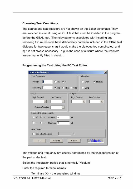
VOLTECH ATI USER MANUAL PAGE 7-87
Choosing Test Conditions
The source and load resistors are not shown on the Editor schematic. They are switched in circuit using an OUT test that must be inserted in the program before the GBAL test. (The relay patterns associated with inserting and removing fixture resistors have deliberately not been included in the GBAL test dialogue for two reasons: a) it would make the dialogue too complicated, and b) it is not always necessary - e.g. in the case of a fixture where the resistors are permanently fitted in circuit).
Programming the Test Using the PC Test Editor
The voltage and frequency are usually determined by the final application of the part under test.
Select the integration period that is normally Medium
Enter the required terminal names:
Terminals (X) - the energized winding.

TESTS AND TEST CONDITIONS
PAGE 7-88 VOLTECH ATI USER MANUAL
Terminals (X) the measured voltage VOUT1
Terminals (Y) the energized terminals for creating a common mode voltage.
Terminals (Y) the measured voltage VOUT2
Note that the PC Editor’s ‘Measure’ button CANNOT be used to determine the test voltage.
Choosing Test Limits
The test limits can be:
% A nominal value together with + and percentage limits.
>< Minimum and maximum values
> A minimum value only
< A maximum value only
Use the PC Editors Measure button (together with a sample part) if you are unsure of the nominal value.
If the "User Offset Enabled" check box is checked, a value can be entered into the edit box. The value entered is then added to any results returned from the AT tester.

VOLTECH ATI USER MANUAL PAGE 7-89
7.1.21 RESP – FREQUENCY RESPONSE
Measurement Range
Test Voltage
Test Frequency
Basic Accuracy
-100dB to +100dB 1mV to 5V 20Hz to 3MHz 1.0dB
Where Used
The frequency response test, RESP, may be used to check that the variation in power loss of a telecommunications or audio transformer over a specified frequency range is less than specified limits.
Measurement Conditions
The RESP test consists of a number of Insertion Loss (ILOS) tests repeated at different frequencies.
The resistors shown are fitted to the test fixture and should be switched out of circuit when making other measurements such as resistance and inductance. This can be done by fitting relays to the fixture and switching them at appropriate points in the test program using OUT tests.
The first ILOS test is made at a reference frequency that is usually near the middle of the band of frequencies of interest. The result of this test is the 0dB reference level. Further ILOS tests are then carried out at user-selected frequencies and the results referred to the reference dB level.

TESTS AND TEST CONDITIONS
PAGE 7-90 VOLTECH ATI USER MANUAL
The result of a RESP test is a single value, chosen as follows: If all the referred ILOS results are at or inside the specified limits, the result of a RESP test is the referred ILOS result that is closest to the limit. If any of the referred ILOS results are outside the specified limits, the RESP result is the referred ILOS result that is furthest away from the limit.
Choosing Test Conditions
The voltage and frequency are usually determined by the final application of the part under test.
0dB
Inse
rtion
Los
s
Frequency
-5dB
-10dB

VOLTECH ATI USER MANUAL PAGE 7-91
Programming the Test Using the PC Test Editor
• Enter the voltage and frequency parameters of the reference test signal.
• Select the integration time required. (Normally 'Medium')
• Enter the names of the Hi and Lo input terminals.
• Enter the names of the Hi and Lo output terminals.
• Add test frequencies as required by entering the frequency and clicking 'add'. There are normally at least 2 additional test frequencies, one at either end of the frequency band of interest. Additional mid band test frequencies can be entered to ensure that the transformer response is 'flat' throughout the band.
• Set the frequency response limits.

TESTS AND TEST CONDITIONS
PAGE 7-92 VOLTECH ATI USER MANUAL
• Select OK. The test specification will then be displayed in the program window.
Note that although resistors should be fitted to the fixture, there is no need to enter their values here since the RESP test result is the difference between two ratios based on the same resistor values. The resistor values cancel out in the calculation.
If the "User Offset Enabled" check box is checked, a value can be entered into the edit box. The value entered is then added to any results returned from the AT tester.

VOLTECH ATI USER MANUAL PAGE 7-93
7.1.22 ILOS – INSERTION LOSS
Measurement Range
Test Voltage
Test Frequency
Basic Accuracy
-100dB to +100dB 1mV to 5V 20Hz to 3MHz 0.5dB
The insertion loss is a measure of the power lost by a transformer relative to the maximum theoretical power that the transformer could transmit to a given load.
Core and winding resistance losses mean that some power is always consumed by a transformer, reducing the power available to the load from the theoretical maximum.
Where Used
The insertion loss test is used to check the power loss of audio and telecommunications transformers. The test helps to ensure that the transformer has been assembled properly using the correct core and winding materials.
Test Conditions
The source and load resistors (RS and RL) are connected to the transformer under test as shown. This may be done automatically using the testers OUT test.

TESTS AND TEST CONDITIONS
PAGE 7-94 VOLTECH ATI USER MANUAL
The tester applies the specified voltage Vin, and the voltage Vout is measured.
The ratio of actual to theoretical power loss is calculated using the formula:
ILOS = 10log10 ((Vin2 RL) / (4 Vout2 RS))
Choosing Test Conditions
The voltage and frequency are usually determined by the final application of the part under test.
Programming the Test Using the PC Test Editor
Note that the PC Editors Measure button CANNOT be used to determine the test voltage.
Select the integration period that is normally Medium
Enter the Input and Output terminal names.
Remember to enter the values of Rs (Source Resistance) and Rl (Load resistance) as used on the fixture.

VOLTECH ATI USER MANUAL PAGE 7-95
Choosing Test Limits
The test limits can be:
% A nominal value together with + and percentage limits.
>< Minimum and maximum values
> A minimum value only
< A maximum value only
Use the PC Editors Measure button (together with a sample part) if you are unsure of the nominal value.
If the "User Offset Enabled" check box is checked, a value can be entered into the edit box. The value entered is then added to any results returned from the AT tester.

TESTS AND TEST CONDITIONS
PAGE 7-96 VOLTECH ATI USER MANUAL
7.1.23 RLOS – RETURN LOSS
Measurement Range
Test Voltage
Test Frequency
Basic Accuracy
-100dB to +100dB 1mV to 5V 20Hz to 3MHz 0.2%
The return loss is a measure of the impedance mismatch between the transformer and a transmission line.
If the impedances are not the same, some signal power is reflected or returned to the transmission line instead of being coupled through the transformer.
Where Used
The return loss test is used to check the impedance of audio and telecommunications transformers that are to be used with transmission lines of specified impedance. The test helps to ensure that the transformer has been assembled properly using the correct core and winding materials.
Test Conditions
The load resistor (RL) is connected to the transformer under test as shown. This may be done automatically using the testers OUT test.
The tester applies the specified voltage and, using harmonic analysis, measures the combined impedance of the transformer and load resistor.
AT SeriesTester
RLImpedance ZM

VOLTECH ATI USER MANUAL PAGE 7-97
The return loss is calculated using the formula:
RLOS = 20 log10 ( ZO + ZM / ZO – ZM )
Where Z is a complex impedance in the form Z= R + jX
Or:
Where:
Ro is the resistive portion of the reference impedance
Rm is the resistive portion of the measured devices impedance
Xo is the reactive portion of the reference impedance
Xm is the reactive portion of the measured devices impedance
Choosing Test Conditions
The voltage and frequency are usually determined by the final application of the part under test. 1000Hz is typical for the mid band of audio telecommunications circuits.
½
(Ro - Rm) + (Xo - Xm) r = 20 log10
(Ro + Rm) + (Xo + Xm) 2 2
2 2

TESTS AND TEST CONDITIONS
PAGE 7-98 VOLTECH ATI USER MANUAL
Programming the Test Using the PC Test Editor
Choose the integration period (normally Medium) and enter the High and Low Terminal names.
The reference impedance values are the nominal values of the transmission line to which the transformer will be connected in its final application. This is a complex impedance Z = R + jX where R is the real part of the impedance and X is the imaginary part. A typical impedance might be 600 Ω resistive only or 600Ω in series with a 2.15uF capacitor. Entering the impedance in terms of R and X allows even more complex networks to be used for the RLOS test. Remember that X, the imaginary impedance, is the impedance at the specified test frequency.

VOLTECH ATI USER MANUAL PAGE 7-99
Xc = 1/ 2ππππfC.
Note that the PC Editor’s ‘Measure’ button CANNOT be used to determine the test voltage.
Choosing Test Limits
The test limits can be:
% A nominal value together with + and percentage limits.
>< Minimum and maximum values
> A minimum value only
< A maximum value only
Use the PC Editor’s ‘Measure’ button (together with a sample part) if you are unsure of the nominal value.
If the "User Offset Enabled" check box is checked, a value can be entered into the edit box. The value entered is then added to any results returned from the AT tester.

TESTS AND TEST CONDITIONS
PAGE 7-100 VOLTECH ATI USER MANUAL
7.1.24 Z, ZB – IMPEDANCE, IMPEDANCE WITH BIAS
Measurement Range
Test Voltage
Test Frequency
Basic Accuracy
1mΩ to 1MΩ 1mV to 5V 20Hz to 3MHz 0.2%
The impedance of a transformer is usually complex, that is it consists of real (resistive) and inductive or capacitive (imaginary) parts. The total impedance at a specified frequency is the vector sum of these parts.
Z = √√√√ (R2 +X2)
Where R and X are the real and imaginary parts of the total impedance.
The impedance test checks the impedance of audio and telecommunications transformers that are to be used with transmission lines of specified impedance. The test helps to ensure that the transformer has been assembled properly using the correct core and winding materials.
Test Conditions
The test may be made on the part alone, or with a load resistor RL attached to the secondary to simulate the load impedance of the transformer when it is used in its final application. The optional load resistor (RL) is connected to the transformer under test as shown. This may be done automatically using the testers OUT test.

VOLTECH ATI USER MANUAL PAGE 7-101
To measure Z, the tester applies the specified voltage and (for impedance with bias, the specified DC bias current). By measuring both the applied AC voltage and the resulting AC current, the total impedance is calculated.
Z is the magnitude of the complex impedance Z = √ (R2 +X2)
Choosing Test Conditions
The voltage and frequency are usually determined by the final application of the part under test. Programming the Test Using the PC Test Editor

TESTS AND TEST CONDITIONS
PAGE 7-102 VOLTECH ATI USER MANUAL
Choose the integration period (normally Medium) and enter the High and Low Terminal names.
For the impedance with bias test, you may also select a DC bias current.
Note that the Editor’s ‘Measure’ button CANNOT be used to determine the test voltage.
Choosing Test Limits
The test limits can be:
% A nominal value together with + and percentage limits.
>< Minimum and maximum values
> A minimum value only
< A maximum value only
Use the PC Editor’s ‘Measure’ button (together with a sample part) if you are unsure of the nominal value.
Remember to click on the units of limits (mOhm, Ohm etc.) when entering absolute values as limits.
Test limits should be set as close as possible to detect assembly faults.
If the "User Offset Enabled" check box is checked, a value can be entered into the edit box. The value entered is then added to any results returned from the AT tester.

VOLTECH ATI USER MANUAL PAGE 7-103
7.1.25 X – REACTANCE
Measurement Range
Test Voltage
Test Frequency
Basic Accuracy
1mΩ to 1MΩ 1mV to 5V 20Hz to 3MHz 0.2%
The impedance of a transformer is usually complex, that is it consists of real (resistive) and inductive or capacitive (imaginary) parts. The total impedance at a specified frequency is the vector sum of these parts.
Z = R + j X
Where R and X are the real and imaginary parts of the total impedance.
Where Used
The X test checks the reactance (or imaginary part of the complex impedance) of audio and telecommunications transformers that are to be used with transmission lines of specified impedance. The test helps to ensure that the transformer has been assembled properly using the correct core and winding materials.
Test Conditions
The test may be made on the part alone, or with a load resistor RL attached to the secondary to simulate the load impedance of the transformer when it is used in its final application. The optional load resistor (RL) is connected to the

TESTS AND TEST CONDITIONS
PAGE 7-104 VOLTECH ATI USER MANUAL
transformer under test as shown. This may be done automatically using the testers OUT test.
To measure X, the tester applies the specified voltage and by measures both the applied voltage and the resulting current. Using harmonic analysis, the measured voltage is divided by the current to obtain a complex impedance from which X, the imaginary part of the impedance, is obtained.
X is the imaginary part of the complex impedance Z = R + jX.
Choosing Test Conditions
The voltage and frequency are usually determined by the final application of the part under test.
The X test is only available on the ATis front panel LCR mode.

VOLTECH ATI USER MANUAL PAGE 7-105
7.1.26 ANGL – PHASE ANGLE OF IMPEDANCE Measurement
Range Test
Voltage Test
Frequency Basic
Accuracy
-360° to +360° 1mV to 5V 20Hz to 3MHz 0.05°
The impedance of a winding is usually complex as it consists of real (resistive) and inductive or capacitive (imaginary) parts. The phase angle φφφφ, of the complex impedance at a specified frequency is:
φφφφ = tan-1 (X / R) Where R and X are the real and imaginary parts of the complex impedance.
See also the impedance test, Z, which measures the magnitude of the impedance:
Z = √√√√ (R2 + X2)
Where Used
An impedance phase angle test may be performed on any ferrite or iron cored winding, but it is an especially important test of audio, telecommunication and other signal components where the angle of the impedance is important.

TESTS AND TEST CONDITIONS
PAGE 7-106 VOLTECH ATI USER MANUAL
Measuring the phase angle of the impedance will help to determine that the part has been properly assembled using the correct cores and the right gauge of wire.
Measurement Conditions
The AT Series Tester applies the specified AC voltage to the winding under test. Using harmonic analysis, the phase angle of the impedance is determined from the measured voltage and the current flowing through the winding.
ANGL is the angle of the complex impedance φ = tan-1 (X / R)
Choosing Test Conditions
The voltage and frequency are usually determined by the final application of the part under test.
Rs
X

VOLTECH ATI USER MANUAL PAGE 7-107
Programming the Test Using the PC Test Editor
Choose the integration period (normally Medium) and enter the High and Low Terminal names.
Note that the PC Editor’s ‘Measure’ button CANNOT be used to determine the test voltage.
Choosing Test Limits
The test limits can be:
+/- A nominal value together with + and limits of up to +90 and 90 deg.
>< Minimum and maximum values
Use the PC editor’s ‘Measure’ button (together with a sample part) if you are unsure of the nominal value.
Test limits should be set as close as possible to detect assembly faults.
If the "User Offset Enabled" check box is checked, a value can be entered into the edit box. The value entered is then added to any results returned from the AT tester.

TESTS AND TEST CONDITIONS
PAGE 7-108 VOLTECH ATI USER MANUAL
7.1.27 PHAS – INTERWINDING PHASE ANGLE
Measurement Range
Test Voltage
Test Frequency
Basic Accuracy
-360° to +360° 1mV to 5V 20Hz to 3MHz 0.05°
When the AC voltage across one winding is compared to the voltage across another, they may be different in amplitude and phase.
Where the turns ratio or open circuit voltage tests measure the amplitude of the voltages, the PHAS test measures the phase difference between the two voltage waveforms.
Where Used
The interwinding phase angle test is most often used on measuring and other signal transformers where the phase displacement of signals is important to the operation of the complete circuit or product.
The test determines the angle, measured in degrees, between the voltage signals across two different windings. This is different to the polarity test

VOLTECH ATI USER MANUAL PAGE 7-109
incorporated into the TR (Turns Ratio) test that can only determine +ve or -ve polarity.
Test Conditions
The AT Series Tester applies the specified AC voltage to one winding and measures the voltage produced across two windings, one of which may be the energized winding.
The phase angle between the voltages is determined using harmonic analysis.
Choosing Test Conditions
The voltage and frequency are usually determined by the final application of the part under test.
Programming the Test Using the PC Test Editor

TESTS AND TEST CONDITIONS
PAGE 7-110 VOLTECH ATI USER MANUAL
Choose the integration period (normally Medium):
Energized Terminals: The terminals where the test signal will be applied. This is normally the winding with the greatest number of turns.
Primary Terminals High and Low: The zero phase reference terminals that are often the same as the energized terminals.
Secondary Terminals High and Low: The inter-winding phase angle measurement will be the angle between the primary and secondary terminals, High and Low Terminal names.
Note that the PC Editor’s ‘Measure’ button CANNOT be used to determine the test voltage.
Choosing Test Limits
The test limits can be:
+/- A nominal value together with + and limits of up to +90 and 90 deg.
>< Minimum and maximum values
Use the PC Editor’s ‘Measure’ button (together with a sample part) if you are unsure of the nominal value.
Test limits should be set as close as possible to detect assembly faults.
If the "User Offset Enabled" check box is checked, a value can be entered into the edit box. The value entered is then added to any results returned from the AT tester.

VOLTECH ATI USER MANUAL PAGE 7-111
7.1.28 TRIM – PAUSE TESTING IN ORDER TO TRIM A COMPONENT VALUE
The TRIM test is used on signal, audio and telecommunications transformers and other components where a means of physically adjusting a parameter is provided. For example, the Q factor of a coil may be tuned to within specified limits by adjusting a trimmable core.
Test Conditions
A TRIM test may be used after any low voltage test on the tester. If the desired parameter is outside the limits specified by that previous test, the tester halts and provides a live display indicating which way (+)ve or (-)ve the operator should adjust the part.
Once trimming is complete the tester will continue with the rest of the tests in the sequence once the run-pad is touched, the Run softkey is pressed or the foot-switch (if fitted) is closed.

TESTS AND TEST CONDITIONS
PAGE 7-112 VOLTECH ATI USER MANUAL
Tests that may be TRIMmed include:
R, RLS, RLP, LS, LP, LSP, LSB, Q, C, TR, LL, LLO, TR, L2, C2, GBAL, LBAL, ILOS, RLOS and Z.
Choosing Test Conditions
On selecting TRIM - Trimming Adjustment from the Available Tests Window, the following dialogue box will be displayed:
To program the test:
Select OK. The test will then be displayed in the program window.

VOLTECH ATI USER MANUAL PAGE 7-113
7.1.29 OUT – CONTROL EXTERNAL DEVICES The AT Series testers normally make all the necessary connections for testing automatically using a matrix of internal relays.
When, for example, an external component such as a resistor is required for testing, then during the test sequence the resistor may be switched into or out of the test circuit using an OUT test. A +12V DC power supply ensures that everything necessary to drive an external 12V DC relay is available.
Pin Signal Name Pin Signal Name 1 o/p User Relay Drive 0 6 o/p User Relay Drive 1 2 o/p User Relay Drive 2 7 o/p User Relay Drive 3 3 o/p User Relay Drive 4 8 o/p User Relay Drive 5 5 o/p +12V 4 & 9 i/p Do Not Use
The OUT test is used to switch external relays at any point in a test sequence. The user relays may in turn be used to switch in external components such as impedance matching resistors (important for audio and telecommunications transformers) or to connect windings in series for subsequent testing. The user port is situated at the rear of the ATi.

TESTS AND TEST CONDITIONS
PAGE 7-114 VOLTECH ATI USER MANUAL
See also the tests for audio and telecommunications transformers, LBAL, GBAL, ILOS, RLOS and Z.
Most types of power and many signal transformers will be tested using the testers internal relay matrix to perform switching, and an OUT test is not required for these.
Test Options
The OUT test is programmed into a test sequence like any other test. The OUT test programmes any of the six available relay drives in any pattern desired. The drives stay in the programmed state until another OUT test is performed or a new part is tested.
The relay drives controlled by the OUT test are designed for switching external user supplied relays only and should NOT be connected directly to the tester’s test nodes.
Choosing Test Options
Each of the relay driver outputs can be set to on or off (closed or open respectively) as shown:
Once the settings are correct click on OK to accept them.

VOLTECH ATI USER MANUAL PAGE 7-115
Note:
The relay drivers are only set as and when the tester encounters an OUT test. The settings given will remain in place until another OUT test is encountered. Therefore if the settings are required for one part of the test program only, two OUT tests will be required, the first to turn the appropriate relay drivers on and the second to turn them back off.
See the Specification for details of the relay driver configuration.

TESTS AND TEST CONDITIONS
PAGE 7-116 VOLTECH ATI USER MANUAL
7.1.30 LSBX – INDUCTANCE WITH EXTERNAL BIAS (SERIES CIRCUIT)
DC Bias Measure Range
Test Voltage
Test Frequency
Basic Accuracy
0.1A to
250A
1nH 1MH 1mV to 5V 20Hz to 3MHz 0.2% @ Q>10
This test requires the use of one or more Voltech DC1000 Precision DC Bias Current Sources. Contact your Voltech sales office for details. The inductance of a transformer winding while an external bias current is flowing through it may be tested using series or parallel equivalent circuit models. Initially the DC bias current is set up and allowed to stabilize. An AC voltage is applied across the selected winding; the voltage across and current through the winding is then measured using harmonic analysis. The measured voltage is divided by the current to obtain a complex impedance and the inductance is calculated.
On selecting LSBX Inductance with External Bias (Series Circuit) from the Available Tests window, a dialogue box will be displayed.

VOLTECH ATI USER MANUAL PAGE 7-117
To program the test:
1. Enter the signal, frequency and bias current required for the test.
Note that the signal is normally entered as a voltage by selecting the mV or V button; but you may optionally enter it as a current by selecting the mA button. (If in doubt refer to the Test Conditions chapter of your AT user manual. Note also that the measure button may be used here, as outlined in your AT user manual, with the combinations of test parameter specification shown in the following table:
Option 1 Option 2 Option 3 Option 4
Signal Specified voltage
Specified current
Auto Auto
Frequency Specified Specified Specified Auto Bias Specified Specified Specified Specified
2. Select (mouse click the button) the integration time you require.
Medium is the default setting. Long will give you more stable readings (for tighter limits) at the expense of test time, and Short will test at the maximum speed, but may give slightly noisier readings.
3. Enter the terminal names between which the inductance will be
measured. By pulling down the menu along side the fill-in box, you may select the high and low terminals for each test.
4. Select (mouse click the button) the type of limits you require, and enter
the values.
% Enter a nominal value and then the limits as negative and positive values.
>< Enter minimum and maximum values.
> Enter just a minimum value. < Enter just a maximum value.
5. Select OK. The test specification will then be displayed in the program window.

TESTS AND TEST CONDITIONS
PAGE 7-118 VOLTECH ATI USER MANUAL
7.1.31 LPBX – INDUCTANCE WITH EXTERNAL BIAS (PARALLEL CIRCUIT)
DC Bias Measure Range
Test Voltage
Test Frequency
Basic Accuracy
0.1A to
250A
1nH 1MH 1mV to 5V 20Hz to 3MHz 0.2% @ Q>10
This test requires the use of one or more Voltech DC1000 Precision DC Bias Current Sources. Contact your Voltech sales office for details. The inductance of a transformer winding while an external bias current is flowing through it may be tested using series or parallel equivalent circuit models. Initially the DC bias current is set up and allowed to stabilize. An AC voltage is applied across the selected winding; the voltage across and current through the winding are then measured using harmonic analysis. The measured voltage is divided by the current to obtain a complex impedance and the inductance is calculated.
On selecting LPBX Inductance with External Bias (Parallel Circuit) from the Available Tests window, a dialogue box will be displayed.

VOLTECH ATI USER MANUAL PAGE 7-119
To program the test:
1. Enter the signal, frequency and bias current required for the test.
Note that the signal is normally entered as a voltage by selecting the ‘mV’ or ‘V’ button; but you may optionally enter it as a current by selecting the ‘mA’ button. (If in doubt refer to the ‘Test Conditions’ chapter of your AT user manual. Note also that the measure button may be used here, as outlined in your AT user manual, with the combinations of test parameter specification shown in the following table:
Option 1 Option 2 Option 3 Option 4
Signal Specified voltage
Specified current
Auto Auto
Frequency Specified Specified Specified Auto Bias Specified Specified Specified Specified
2. Select (mouse click the button) the integration time you require.
‘Medium’ is the default setting. ‘Long’ will give you more stable readings (for tighter limits) at the expense of test time, and ‘Short’ will test at the maximum speed, but may give slightly noisier readings.
3. Enter the terminal names between which the inductance will be
measured. By pulling down the menu along side the fill-in box, you may select the high and low terminals for each test.
4. Select (mouse click the button) the type of limits you require, and enter
the values.
% Enter a nominal value and then the limits as negative and positive values.
>< Enter minimum and maximum values.
> Enter just a minimum value. < Enter just a maximum value.
5. Select OK. The test specification will then be displayed in the program window.

TESTS AND TEST CONDITIONS
PAGE 7-120 VOLTECH ATI USER MANUAL
7.1.32 ZBX - IMPEDANCE WITH EXTERNAL BIAS
DC Bias Measurement Range
Test Voltage
Test Frequency
Basic Accuracy
0.1A to 250A 1mΩ to 1MΩ 1mV to 5V
20Hz to 3MHz
0.2%
This test requires the use of one or more Voltech DC1000 Precision DC Bias Current Sources. Contact your Voltech sales office for details.
The Winding Impedance with External Bias test measures the impedance of a selected winding while applying a DC current from the DC1000 through the winding. An AC voltage is also applied across the winding from the AT. This test can be used with inductors to measure the change in impedance with a bias current. On selecting ZBX Impedance with External Bias from the available tests window, the following dialog box is displayed:

VOLTECH ATI USER MANUAL PAGE 7-121
To program the test: 1. Enter the value of a voltage (or current) for the signal and the required
frequency of the test.
Also enter the bias current you would like to apply.
Please note that the Measure button may be used here. For information, refer to the Test Program Editor of your AT manual.
2. Select the integration time required. Medium is the default setting. Long will give more stable readings (for tighter limits) at the expense of time, and Short will test at the maximum speed, but may give slightly noisier readings.
3. Enter the terminal names between which the impedance is to be
measured.
4. Set the impedance limits.
+/- Enter a nominal value and then the limits as negative and positive values.

TESTS AND TEST CONDITIONS
PAGE 7-122 VOLTECH ATI USER MANUAL
>< Enter minimum and maximum values. > Enter just a minimum value.
< Enter just a maximum value.
5. Select OK. The test specification will then be displayed in the program window.

VOLTECH ATI USER MANUAL PAGE 7-123
7.2 SERIES AND PARALLEL CIRCUITS
The ATi can make measurements of many parameters such as Inductance (L), Capacitance (C) and AC resistance (R) using both the parallel and equivalent circuits.
The measurements for the series or parallel equivalent circuits will not necessarily be the same and care should be taken when choosing which equivalent circuit to use when testing.
Any practical inductor or capacitor will not be perfect, and will have associated stray parallel and series resistance in its equivalent circuit.
Where
X is the purely imaginary (inductive or capacitive) impedance
Rp is the stray parallel resistance
Rs is the stray series resistance.
Rp
X
Rs

TESTS AND TEST CONDITIONS
PAGE 7-124 VOLTECH ATI USER MANUAL
For an INDUCTIVE IMPEDANCE, Rs represents the copper losses in the wire and Rp represents the in-phase core losses. X (ωL) is usually much lower than Rp, so Rp is insignificant. Choose the SERIES equivalent circuit.
If the inductance is large (> 1 Henry) and / or the series resistance (Rs) is very small, the parallel equivalent circuit is sometimes used.
For a CAPACITIVE IMPEDANCE, X is usually much higher than Rp, making Rp very significant. Choose the PARALLEL equivalent circuit
If the capacitance is large (small impedance) then Rp will be insignificant and the series equivalent circuit can be chosen.

VOLTECH ATI USER MANUAL PAGE 7-125
7.3 CAPACITOR MEASUREMENTS
The ATi and its front panel LCR mode are ideal for making precise measurements on capacitors.
Capacitance (Farads)
To measure the capacitance, use the C test in the PC editor or simply select C on the top line of the LCR mode. The measurement conditions can be fully automatic or user programmed following the guidelines given earlier in this chapter. Measurements are usually made using the parallel equivalent circuit (see the preceding section).
D Dissipation Factor or tanδδδδ
D can be selected as a second line parameter of the LCR mode. D is a measure of the losses in a capacitor and is defined to be:
D = energy lost = Real part of impedance (Rs) = tan δδδδ Energy stored Imaginary part of impedance (X) Where δδδδ is the angle between the total complex impedance, Z., and the imaginary axis.
Z
Φ
Rs
X
ii
r

TESTS AND TEST CONDITIONS
PAGE 7-126 VOLTECH ATI USER MANUAL
ESR Equivalent Series Resistance
This is also a measure of the losses in the capacitor. The ESR is the equivalent AC resistance of the series equivalent circuit. To measure ESR, choose the test RLS in the PC editor or select Rs SERIES circuit from the front panel LCR mode. Use the test conditions determined for the C test.
ESR is a measure of equivalent AC resistance at a specified frequency and will be different to the expected DC resistance of contacts and leads.
Compensation
For most capacitors, and especially film and ceramic types, the dissipation factor will be very low; typically < 0.01. The errors due to connections and lead impedances can thus be very significant. For the best accuracy always use 4 terminal connections and perform compensation before recording measurements

VOLTECH ATI USER MANUAL PAGE 8-1
8 SPECIFICATIONS

SPECIFICATIONS
PAGE 8-2 VOLTECH ATI USER MANUAL

SPECIFICATIONS
VOLTECH ATI USER MANUAL PAGE 8-3
Contents - Specifications 8.1. SPECIFICATIONS SUMMARY – AVAILABLE TESTS ......................................8-5 8.2. ACCURACY SPECIFICATIONS – AVAILABLE TESTS.....................................8-8
8.2.1. R Test.......................................................................................................... 8-8 8.2.2. LS, LP, LSB, LPB, RLS, RLP and X Tests .................................................. 8-9 8.2.3. LL and LLO Tests...................................................................................... 8-10 8.2.4. C, CS and CP Tests .................................................................................. 8-11 8.2.5. QL and D Tests ......................................................................................... 8-12 8.2.6. TR Test ..................................................................................................... 8-13 8.2.7. LVOC Test ................................................................................................ 8-14 8.2.8. TRL Test ................................................................................................... 8-15 8.2.9. IR Test....................................................................................................... 8-16 8.2.10. L2, C2 and R2 Tests ............................................................................... 8-17 8.2.11. GBAL Test............................................................................................... 8-18 8.2.12. LBAL, ILOS and RESP Tests.................................................................. 8-19 8.2.13. RLOS Test .............................................................................................. 8-20 8.2.14. Z and ZB Test.......................................................................................... 8-21 8.2.15. ANGL Test .............................................................................................. 8-22 8.2.16. PHAS Test .............................................................................................. 8-23 8.2.17. LSBX and LPBX Tests ............................................................................ 8-24
8.3. INTERFACE DETAILS...............................................................................8-25 8.3.1. Barcode Port ............................................................................................. 8-25 8.3.2. Server Port ................................................................................................ 8-27 8.3.3. Auxiliary Port ............................................................................................. 8-27 8.3.4. Printer Port ................................................................................................ 8-28 8.3.5. Remote Port .............................................................................................. 8-29 8.3.6. User Port ................................................................................................... 8-31 8.3.7. Environmental Conditions ......................................................................... 8-34

SPECIFICATIONS
PAGE 8-4 VOLTECH ATI USER MANUAL
8.4. EMC COMPLIANCE................................................................................ 8-35 8.4.1. Declaration of Conformity.......................................................................... 8-35 8.4.2. EMC Precautions ...................................................................................... 8-36

SPECIFICATIONS
VOLTECH ATI USER MANUAL PAGE 8-5
8.1 SPECIFICATIONS SUMMARY – AVAILABLE TESTS
Test
User-Entered Test Data
Measurement Range Test Signal Test Frequency
AR
(1)
CTY Continuity 10kΩ - 10MΩ n/a n/a n/a
R DC Resistance
10µΩ - 10MΩ n/a n/a 0.1%
R2 DC Resistance Match
1:1000 - 1000:1 n/a n/a 0.2%
LS LSB
Inductance (Series) + Bias
1nH - 1MH 1mV - 5V 20Hz - 3MHz 0.05%
LP LPB
Inductance (Parallel) + Bias
1nH - 1MH 1mV - 5V 20Hz - 3MHz 0.05%
QL Quality Factor
0.001 - 1000 1mV - 5V 20Hz - 3MHz 0.5%
D Dissipation Factor (tanδ)
0.001 - 1000 1mV - 5V 20Hz - 3MHz 0.5%
RLS Equivalent Series Resistance
10µΩ - 10MΩ 1mV - 5V 20Hz - 3MHz 0.05%
RLP Equivalent Parallel Resistance
10µΩ - 10MΩ 1mV - 5V 20Hz - 3MHz 0.05%
LL Leakage Inductance
1nH - 1kH 20µA - 100mA 20Hz - 3MHz 0.1%
LL0 Leakage Inductance with Offset
1nH - 1kH 20µA - 100mA 20Hz - 3MHz 0.1%
C Interwinding Capacitance
100fF - 1mF 1mV - 5V 20Hz - 3MHz 0.1%
CP Capacitance (Parallel)
100fF - 1mF 1mV - 5V 20Hz - 3MHz 0.1%
CS Capacitance (Series)
100fF - 1mF 1mV - 5V 20Hz - 3MHz 0.1%
X Reactance 1mΩ - 1MΩ 1mV - 5V 20Hz - 3MHz 0.2%
TR Turns Ratio and Phasing
1:100k - 100k:1 1mV - 5V 20Hz - 3MHz 0.1%

SPECIFICATIONS
PAGE 8-6 VOLTECH ATI USER MANUAL
Test User-Entered Test Data Measurement Range Test Signal Test Frequency
AR(1)
TRL Turns Ratio by Inductance
30:1 - 1:30 1mV - 5V 20Hz - 3MHz 0.1%
LVOC Low Voltage Open Circuit 100µV - 5V 1mV - 5V 20Hz - 3MHz 0.1%
IR Insulation Resistance 1MΩ - 10GΩ 100V - 500V n/a 1.0%
L2 Inductance Match 1:10000 - 10000:1 1mV - 5V 20Hz - 3MHz 0.1%
C2 Interwinding Capacitance Match
1:1000 - 1000:1 1mV - 5V 20Hz - 3MHz 0.2%
GBAL General Longitudinal Balance
0dB - 100dB 1mV - 5V 20Hz - 3MHz 0.5dB
LBAL Longitudinal Balance
0dB - 100dB 1mV - 5V 20Hz - 3MHz 0.5dB
ILOS Insertion Loss -100dB - 100dB 1mV - 5V 20Hz - 3MHz 0.5dB
RESP Frequency Response
-100dB - 100dB 1mV - 5V 20Hz - 3MHz 1.0dB
RLOS Return Loss -100dB - 100dB 1mV - 5V 20Hz - 3MHz 0.2% Z Impedance 1mΩ - 1MΩ 1mV - 5V 20Hz - 3MHz 0.2%
ZB Impedance with Bias
1mΩ - 1MΩ 1mV - 5V 20Hz - 3MHz 0.2%
ANGL Impedance Phase Angle -360° - 360° 1mV - 5V 20Hz - 3MHz 0.05°
PHAS Interwinding Phase Test
-360° - 360° 1mV - 5V 20Hz - 3MHz 0.05°
TRIM Trimming Adjustment
n/a n/a n/a n/a
OUT Output to User Port
n/a n/a n/a n/a
LSBX
Inductance with External Bias (Series Circuit) DC Bias
100nH to 100H 1mV to 5V or
20µA to 100mA
20Hz to 3MHz 0.2%
LPBX
Inductance with External Bias (Parallel Circuit) DC Bias
100nH to 100H 1mV to 5V or
20µA to 100mA
20Hz to 3MHz 0.2%

SPECIFICATIONS
VOLTECH ATI USER MANUAL PAGE 8-7
ZBX
Impedance with External Bias
1mΩ to 1MΩ 1mV to 5V or
20µA to 100mA
20Hz to 3MHz 0.2%
Notes 1. AR = basic relative accuracy; full specifications follow.
Specification at 23ºC ± 5ºC after one-hour warm-up and long integration. 2. Absolute maximum ratings for all tests: 5Vrms and 0.4Apeak (except IR
500VDC). 3. Where used, the bias current accuracy is +/-10% of the requested value.
SPECIFICATIONS
PAGE 8-8 VOLTECH ATI USER MANUAL
8.2 ACCURACY SPECIFICATIONS – AVAILABLE TESTS
8.2.1 R TEST
The accuracy is based on the test conditions chosen to measure the winding resistance, and is given as:
Where
AT is the total accuracy (%)
AR is the basic relative accuracy (%)
AC is the calibration accuracy (%)
AV is the correction for voltage level (%)
AI is the correction for current level (%)
The value of AR is given in the table in section 8.1 of this chapter.
The values of the other factors are given below.
Where
VM is the measured voltage (V)
IM is the measured current (A)
A V ) = 0.03% + (0.01% / V M
A = 0.2%C
A I )I = 0.03% + (0.01% / M
A = AT R C V I+A +A +A

SPECIFICATIONS
VOLTECH ATI USER MANUAL PAGE 8-9
8.2.2 LS, LP, LSB, LPB, RLS, RLP AND X TESTS
The accuracy is based on the test conditions chosen to measure the impedance of the parameter under test, and is given as:
AT = AR + AC + AV + AI + AQ + AB
Where
AT is the total accuracy (%)
AR is the basic relative accuracy (%)
AC is the calibration accuracy (%)
AV is the correction for voltage level (%)
AI is the correction for current level (%)
AQ is the correction for Q factor (%)
AB is the correction for Bias (%)
The value of AR is given in the table in section 8.1 of this chapter. The values of the other factors are given below.
AC = 0.08% + (0.00001% x FM)
AV = 0.08% + (0.001% / VM)
AI = 0.08% + (0.0001% / IM) + (0.03% x IB / IM)
AQ = 0.08% + (2% / QM) (LS, LP, LSP, LPS and X)
AQ = 0.08% + (2% x QM) (RLS and RLP)
AB = 0.03% x IB / IM
Where
FM is the measurement frequency (Hz)
VM is the measured voltage (V)
IM is the measured current (A)
IB is the bias current (A).
QM is the Q factor of the measured impedance

SPECIFICATIONS
PAGE 8-10 VOLTECH ATI USER MANUAL
8.2.3 LL AND LLO TESTS The accuracy is based on the test conditions chosen to measure the impedance of the parameter under test, and is given as:
AT = AR + AC + AV + AI + AQ + AB + ASC
Where
AT is the total accuracy (%)
AR is the basic relative accuracy (%)
AC is the calibration accuracy (%)
AV is the correction for voltage level (%)
AI is the correction for current level (%)
AQ is the correction for Q factor (%)
ASC is the correction factor for the short-circuit impedance (%)
The value of AR is given in the table in section 8.1 of this chapter. The values of the other factors are given below.
AC = 0.08% + (0.00001% x FM)
AV = 0.08% + (0.001% / VM)
AI = 0.08% + (0.0001% / IM)
AQ = 0.08% + (2% / QM)
AB = 0.03% x IB / IM
ASC = ZSC x (Turns Ratio)2 x 100 / (Measured LL)
Where
FM is the measurement frequency (Hz)
VM is the measured voltage (V)
IM is the measured current (A)
IB is the bias current (A).
QM is the Q factor of the measured impedance
ZSC is the impedance of the applied short circuit
See Chapter 7, 'Tests and Test Conditions', for a guidance on ASC.

SPECIFICATIONS
VOLTECH ATI USER MANUAL PAGE 8-11
8.2.4 C, CS AND CP TESTS The accuracy is based on the test conditions chosen to measure the impedance of the parameter under test, and is given as:
Where AT is the total accuracy (%) AR is the basic relative accuracy (%) AC is the calibration accuracy (%) AV is the correction for voltage level (%) AI is the correction for current level (%) AQ is the correction for Q factor (%) AF is the correction for C (%)
The value of AR is given in the section 1.1 of this chapter.
The values of the other factors are given below.
MC FA ×+= %00001.0%08.0
MV VA %001.0%08.0 +=
MI IA %0001.0%08.0 +=
MQ QA %2%08.0 +=
Where FM is the measurement frequency (Hz) VM is the measured voltage (V) IM is the measured current (A) QM is the Q factor of the measured impedance CM is the capacitance of the measured impedance
FQIVCRT AAAAAAA +++++=
××=
−
10010300 15
MF C
A

SPECIFICATIONS
PAGE 8-12 VOLTECH ATI USER MANUAL
8.2.5 QL AND D TESTS
The accuracy of measuring Q factor and D factor is given as:
AT = AR + AI + AQD
Where
AT is the basic total accuracy (%)
AR is the basic relative accuracy (%)
AI is the correction for current level (%)
AQD is the correction for Q or D factor (%)
The value of AR is given in the table in section 8.1 of this chapter.
The values of the other factors are given below.
AI = 0.08% + (0.0001%/Im)
AQD = 0.2% x (QM + (1/ QM)) (Q factor)
AQD = 0.2% x (DM + (1/ DM)) (D factor)
Where
QM is the Q factor of the measured impedance
DM is the D factor of the measurement impedance
IM is the measured current (A)

SPECIFICATIONS
VOLTECH ATI USER MANUAL PAGE 8-13
8.2.6 TR TEST
The accuracy is based on the test conditions chosen to measure the turns ratio, and is given as:
Where
AT is the total accuracy (%)
AR is the basic relative accuracy (%)
AC is the calibration accuracy (%)
APV is the correction for primary voltage level (%)
ASV is the correction for secondary voltage level (%)
AN is the correction for the turns ratio value (%)
The value of AR is given in the table in section 8.1 of this chapter.
The values of the other factors are given below.
AC = 0.1% + (0.00003% x FM)
APV = 0.1% + (0.01% / VPM)
ASV = 0.1% + (0.01% / VSM)
AN = 0.1% + (0.1 / NM)
Where
FM is the measurement frequency (Hz)
VPM is the measured primary voltage (V)
VSM is the measured secondary voltage (V)
NM is the measured turns ratio (primary / secondary)
A = AT R C PV SV N+A +A +A +A
SPECIFICATIONS
PAGE 8-14 VOLTECH ATI USER MANUAL
8.2.7 LVOC TEST The accuracy for measuring open circuit voltage is given as:
VCRT AAAA ++=
Where AT is the total accuracy (%) AR is the basic relative accuracy (%) AC is the calibration accuracy (%) AV is the correction for voltage level (%)
The value of AR is given in the section 8.1 of this chapter.
The values of the other factors are given below.
MC FA ×+= %001.0%03.0
MV VA %001.0%03.0 +=
Where FM is the measurement frequency (Hz) VM is the measured voltage (V)
SPECIFICATIONS
VOLTECH ATI USER MANUAL PAGE 8-15
8.2.8 TRL TEST The accuracy for the test is given as:
SPT AAA +=
Where
AT is the total accuracy (%).
AP is the accuracy of the primary winding measurement (%).
AS is the accuracy of the secondary winding measurement (%).
To determine the values of AP and AS use the accuracy specification for series inductance.

SPECIFICATIONS
PAGE 8-16 VOLTECH ATI USER MANUAL
8.2.9 IR TEST
The accuracy is based on the test conditions chosen to measure the insulation resistance, and is given as:
Where
AT is the total accuracy (%)
AR is the basic relative accuracy (%)
AC is the calibration accuracy (%)
AI is the correction for current level (%)
AZ is the correction for impedance level (%)
The value of AR is given in the table in section 8.1 of this chapter.
The values of the other factors are given below.
Where
IM is the measured current (A)
ZM is the measured IR value (MΩ)
A = C 0.03%
A = + ( I )I 3.2% 0.000002% / M
A = 0.5% + (0.001% ZxZ M )
A = AT R C I Z+A +A +A

SPECIFICATIONS
VOLTECH ATI USER MANUAL PAGE 8-17
8.2.10 L2, C2 AND R2 TESTS
The accuracy is dependent on the accuracy of the two inductance, capacitance or resistance measurements made, and is given as:
Where
AT is the total accuracy (%)
AX is the accuracy of the X measurement (%)
AY is the accuracy of the Y measurement (%)
Refer to the accuracy specifications for the LS, C and R tests to determine the accuracy of the X and Y measurements.
A = AT X Y+A

SPECIFICATIONS
PAGE 8-18 VOLTECH ATI USER MANUAL
8.2.11 GBAL TEST The accuracy is based on the test conditions chosen to measure the longitudinal balance of the transformer under test, and is given as:
Where
AT is the total accuracy (dB)
AR is the basic relative accuracy (dB)
AC is the correction for calibration
AVX is the correction for the X measurement voltage level
AVY is the correction for the Y measurement voltage level
The value of AR is given in the table in section 8.1 of this chapter
The values of the other factors are given below.
Where
FM is the measurement frequency (Hz)
VMX is the measured voltage for the X measurement (V)
VMY is the measured voltage for the Y measurement (V)
∆VCMNX is the error due to the common mode voltage in the X measurement
∆VCMNY is the error due to the common mode voltage in the Y measurement
The error due to the common mode voltage in the measurement (∆VCMNX and ∆VCMNY) is given as
Where
VCMN is the common mode voltage measured
A = C 0.1 + (0.0000001% )x FM
A = AT R C VX VY+0.87(A +A +A )
∆V = VCMN CMN M * 1+ (0.00000001 / 398x F )2

SPECIFICATIONS
VOLTECH ATI USER MANUAL PAGE 8-19
8.2.12 LBAL, ILOS AND RESP TESTS The accuracy is given as:
Where
AT is the total accuracy (dB)
AR is the basic relative accuracy (dB)
AC is the correction for calibration
AVI is the correction for the input voltage level
AVO is the correction for the output voltage level
The value of AR is given in the table in section 8.1 of this chapter.
The values of the other factors are given below.
Where
FM is the measurement frequency (Hz)
VMI is the measured input voltage (V)
VMO is the measured output voltage (V)
A = C 0.1 + (0.0000001% )x FM
A = AT R C VI VO+0.87 A +A +A( )

SPECIFICATIONS
PAGE 8-20 VOLTECH ATI USER MANUAL
8.2.13 RLOS TEST The accuracy is given as:
Where
AT is the total accuracy (dB)
AZ is the total accuracy for the Z test (%)
Z is VM / IM
ZR is 22imagreal ZZ +
Where
VM is the measured voltage (V)
IM is the measured current (A)
Zreal is the real part of the reference impedance (Ω)
Zimag is the imaginary part of the reference impedance (Ω)
A = T 0.174 x ( )x ZZ R
( )x Z Z R2 2 x AZ

SPECIFICATIONS
VOLTECH ATI USER MANUAL PAGE 8-21
8.2.14 Z AND ZB TEST The accuracy is given as:
Where
AT is the total accuracy (%)
AR is the basic relative accuracy (%)
AC is the calibration accuracy (%)
AV is the correction for voltage level (%)
AI is the correction for current level (%)
The value of AR is given in the table in section 8.1 of this chapter. The values of the other factors are given below.
Where
FM is the measurement frequency (Hz)
VM is the measured voltage (V)
IM is the measured current (A)
IB is the bias current (A).
A = C 0.08% + (0.0000001% x FM )A = V 0.08% + (0.000003% / VM )A = I 0.08% + (0.0000003% / IM )
A = AT R C V I+A +A +A
+ (0.03% x IB / IM)

SPECIFICATIONS
PAGE 8-22 VOLTECH ATI USER MANUAL
8.2.15 ANGL TEST The accuracy is given as:
Where
AT is the total accuracy (°)
AR is the basic relative accuracy (°)
AC is the calibration accuracy (°)
AV is the correction for voltage level (°)
AI is the correction for current level (°)
The value of AR is given in the table in section 8.1 of this chapter. The values of the other factors are given below.
Where
FM is the measurement frequency (Hz)
VM is the measured voltage (V)
IM is the measured current (A)
IB is the bias current (A).
A = C 0.03 + (0.0000005% x FM )A = V 0.03 + (0.000003% / VM )A = I 0.03 + (0.0000003% / IM )
A = AT R C V I+A +A +A
+ (0.03% x IB / IM)

SPECIFICATIONS
VOLTECH ATI USER MANUAL PAGE 8-23
8.2.16 PHAS TEST The accuracy is given as:
Where
AT is the total accuracy (°)
AR is the basic relative accuracy (°)
AC is the calibration accuracy (°)
AV is the correction for voltage level (°)
AN is the correction for turns ratio (°)
The value of AR is given in the table in section 8.1 of this chapter.
The values of the other factors are given below.
Where
FM is the measurement frequency (Hz)
VP is the measured voltage across the primary winding (V)
TR is the turns ratio between the primary and secondary windings
A = C 0.000005% x FM A = V 0.002 ((1 / V TR VP P ) + ( / ))A = N 0.05 ( - ( / | V V TRP P ) )|
A = AT R C V N+A +A +A

SPECIFICATIONS
PAGE 8-24 VOLTECH ATI USER MANUAL
8.2.17 LSBX AND LPBX TESTS
The accuracy is based on the test conditions chosen to measure the impedance of the parameter under test, and is given as:
AT = AR + AC + AV + AI + AQ + AB
Where
AT is the total accuracy (%)
AR is the basic relative accuracy (%)
AC is the calibration accuracy (%)
AV is the correction for voltage level (%)
AI is the correction for current level (%)
AQ is the correction for Q factor (%)
AB is the correction for Bias (%)
The value of AR is given in the table in section 8.1 of this chapter. The values of the other factors are given below.
AC = 0.08% + (0.00001% x FM)
AV = 0.08% + (0.001% / VM)
AI = 0.08% + (0.0001% / IM) + (0.03% x IB / IM)
AQ = 0.08% + (2% / QM) (LS, LP, LSP, LPS and X)
AQ = 0.08% + (2% x QM) (RLS and RLP)
AB = % error from DC1000 Specification (refer to DC1000 user manual).
Where
FM is the measurement frequency (Hz)
VM is the measured voltage (V)
IM is the measured current (A)
IB is the bias current (A).
QM is the Q factor of the measured impedance

SPECIFICATIONS
VOLTECH ATI USER MANUAL PAGE 8-25
8.3 INTERFACE DETAILS
The following interfaces are available at the rear of the ATi:
From left to right:
Barcode Server Printer Auxiliary (Editor) Remote User Ground
All these ports may be susceptible to damage from static discharge. Switch off and observe anti-static precautions when making connections.
8.3.1 BARCODE PORT RS232 interface for barcode entry
9-pin female D-type connector
Baud rate: 9600
Parity: None
Stop bits: 1
!

SPECIFICATIONS
PAGE 8-26 VOLTECH ATI USER MANUAL
Pin Signal name Pin Signal name 1 No connection 6 No connection 2 i/p RX 7 0V 3 o/p TX 8 No connection 4 No connection 9 +5V 5 No connection
The recommended barcode reader for the AT Series Testers is the Smart Wand Barcode Reader from Hewlett Packard, (available from Farnell Electronic Components.)
Hewlett-Packard List No: HBSW-8300
The HP Smart Wand reader connects directly to the barcode port; no extra interfacing is required to configure the HBSW-8300. Plug the barcode reader into the port and switch the AT on. The barcode reader is configured correctly as supplied by HP. If the settings have been changed, reset the wand by plugging it in into the tester, switching the tester on and swiping the codes below:
9600 Baud
0’s Parity (none)
1 Stop bit

SPECIFICATIONS
VOLTECH ATI USER MANUAL PAGE 8-27
8.3.2 SERVER PORT RS232 interface for connection to a PC Server running the Voltech AT Series Server software.
25-pin male D-type connector.
Pin Signal name Pin Signal name 1 Ground (Earth) 6 No connection 2 i/p RX 7 0V 3 o/p TX 8 No connection 4 i/p CTS ... 5 o/p RTS 25 No connection
8.3.3 AUXILIARY PORT RS232 interface for connection to a PC running the Voltech AT Series Editor software.
9-pin male D-type connector.
Pin Signal name Pin Signal name 1 No connection 6 No connection 2 o/p TX 7 i/p CTS 3 i/p RX 8 o/p RTS 4 No connection 9 No connection 5 0V

SPECIFICATIONS
PAGE 8-28 VOLTECH ATI USER MANUAL
8.3.4 PRINTER PORT Standard parallel printer interface.
25-pin female D-type connector.
Pin Signal name Pin Signal name 1 o/p !STROBE 11 i/p BUSY 2 o/p D0 12 i/p PE 3 o/p D1 13 No connection 4 o/p D2 14 o/p !AUTOFD 5 o/p D3 15 i/p !ERROR 6 o/p D4 16 o/p !INIT 7 o/p D5 17 o/p !SLCTIN 8 o/p D6 18 0V 9 o/p D7 ...
10 i/p !ACKNLG 25 0V
Signals with a name starting with ! are active Lo.
Printing options can be chosen from the Options dialogue of the Editor software.
If you intend to print all results for each program you will need a high-speed thermal printer or similar.
There are no options fro printing from the LCR modes.
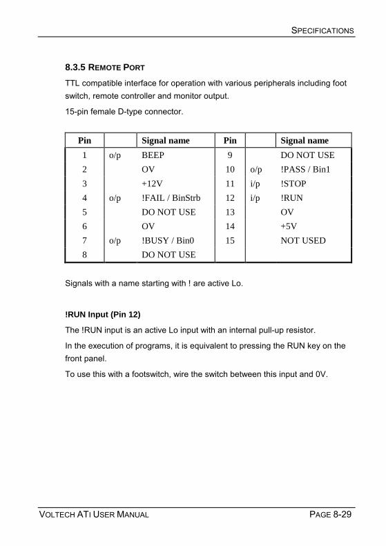
SPECIFICATIONS
VOLTECH ATI USER MANUAL PAGE 8-29
8.3.5 REMOTE PORT TTL compatible interface for operation with various peripherals including foot switch, remote controller and monitor output.
15-pin female D-type connector.
Pin Signal name Pin Signal name 1 o/p BEEP 9 DO NOT USE 2 OV 10 o/p !PASS / Bin1 3 +12V 11 i/p !STOP 4 o/p !FAIL / BinStrb 12 i/p !RUN 5 DO NOT USE 13 OV 6 OV 14 +5V 7 o/p !BUSY / Bin0 15 NOT USED 8 DO NOT USE
Signals with a name starting with ! are active Lo.
!RUN Input (Pin 12)
The !RUN input is an active Lo input with an internal pull-up resistor.
In the execution of programs, it is equivalent to pressing the RUN key on the front panel. To use this with a footswitch, wire the switch between this input and 0V.

SPECIFICATIONS
PAGE 8-30 VOLTECH ATI USER MANUAL
!STOP Input (Pin 11)
The !STOP input is an active Lo input with an internal pull-up resistor.
The active-going edge of this input halts all Tester activity, turning off all signal sources.
To use this with an emergency stop switch, wire the switch between this input and 0V. Fail, Busy and Pass Outputs (Pins 4, 7 and 10)
The status outputs are standard 5 Volt logic signals.
In the standard set-up, the three status outputs are active Lo signals which duplicate the three LEDs on the front panel - Busy, Pass and Fail. They could, for example, be connected as status inputs to a robot controller, or a bin selector.
Beep Output (Pin 1)
This is an active Hi output that copies the internal beeper.
It is configured in the test program header (see the Test Editor section of this manual).
All the outputs (pins 1, 4, 7 and 10) are fitted with 1kΩ protection resistors, and therefore they cannot directly drive external high current loads such as indicators, or bin-select relays. Minimum input resistance of devices connected to these outputs to be 10kΩ.
DO NOT USE (Pins 5, 8 and 9)
These pins are intended for use with Voltech approved accessories and must be left unconnected.
DANGER: Pin 8 may have voltages of up to 500V present during normal operation of the ATi.
1kΩ
!

SPECIFICATIONS
VOLTECH ATI USER MANUAL PAGE 8-31
+12V (pin 3)
Total maximum current
(Remote port pin 3 + User port pin 5) = 100mA
+5V (pin 14)
Maximum current : 800mA
8.3.6 USER PORT
The port contains six open-collector relay drive outputs, and two HC MOS compatible inputs.
The relay drives are switched on and off by certain optional tests (e.g. the OUT test) inserted into your test program. This will enable you, for example, to switch a dummy load on to the secondary winding of the transformer under test, so that subsequent tests are performed on the loaded transformer.
The user port connections must always be fully isolated from the test nodes. A coil to contact isolation of 1000V is recommended for the relay.

SPECIFICATIONS
PAGE 8-32 VOLTECH ATI USER MANUAL
Connector Details
9-pin female D-type connector.
Pin Signal name Pin Signal name 1 o/p User Relay Drive 0 6 o/p User Relay Drive 1 2 o/p User Relay Drive 2 7 o/p User Relay Drive 3 3 o/p User Relay Drive 4 8 o/p User Relay Drive 5 4 i/p User Input 0 9 i/p User Input 1 5 o/p +12V
User Relay Drive Outputs (pins 1, 2, 3, 6, 7 and 8)
All the user Relay Drive Outputs have the following equivalent circuit:
Specification:
Relay coil resistance: > 150Ω
Maximum sink current: 80mA per output

SPECIFICATIONS
VOLTECH ATI USER MANUAL PAGE 8-33
User Inputs (pins 4 and 9)
The User Inputs have the following equivalent circuit:
Specification:
Maximum input voltage: +5V
Minimum input voltage: 0V
Minimum logic 1 input: 4V
Maximum logic 0 input: 0.25V
The zero reference voltage for these inputs is the 0V(ground) 4mm socket situated on the right of the ATi unit. The user inputs have no function at present and should be left unconnected.
+12V (pin 5) Total maximum current (User port pin 5 + Remote port pin 3) = 100mA
+5V
+kΩUserInput

SPECIFICATIONS
PAGE 8-34 VOLTECH ATI USER MANUAL
D
A
E
A
B
C
8.3.7 ENVIRONMENTAL CONDITIONS Line Input
IEC 3-pin socket
87 to 265V ac 47 or 440Hz @100VA
Fuse 1.6AT
Dielectric Strength
2kV ac 50Hz for 1 minute, line input to case.
Storage Temperature
-40° to +70°C
Operating Temperature
0° to 40°C
Humidity
10 to 90% RH non-condensing
Mechanical
Weight: approx. 5.5kg
A = 65mm Height of front edge
B = 434mm Full length
C = 147mm Rear height
Width = 387mm

SPECIFICATIONS
VOLTECH ATI USER MANUAL PAGE 8-35
8.4 EMC COMPLIANCE 8.4.1 DECLARATION OF CONFORMITY
Manufacturer's Name:
DECLARATION OF CONFORMITY Voltech Instruments Ltd
65 Milton Park Abingdon, Oxon United Kingdom
Transformer Tester
Signed on behalf of Voltech Instruments Ltd
ATi
BS EN 61010 (1993) + amendment A2 1995
The product herewith complies with the requirements of the EMC Directives 89/336/EEC and 92/31/EEC and the Low Voltage Directive 73/23/EEC
BS EN 55022 (1995): Class A BS EN 50082-2 (1995)
Manufacturer's Address:
Declares, that the product
Product Name:
Model Number:
conforms to the following product specifications
Safety:
EMC:
Supplementary Information:
Abingdon, United Kingdom, April 25, 2000
Martin Whitley, Quality Manager

SPECIFICATIONS
PAGE 8-36 VOLTECH ATI USER MANUAL
8.4.2 EMC PRECAUTIONS
Conducted and Radiated Emissions
The ATi complies with the limits of BS EN 55022 Class A.
Immunity
The ATi may be susceptible to Fast Electrical Transients on the power line and Electrostatic Discharges, which can disrupt the operation of the unit.
In the event of these circumstances, return the ATi to normal operation by:
1) Switching off the power
2) Waiting for 5 seconds
3) Switching on again
Observe anti-static precautions when making connections to the interfaces on the rear panel of the instrument.
!

VOLTECH ATI USER MANUAL PAGE 9-1
9 WARRANTY AND SERVICE

WARRANTY AND SERVICE
PAGE 9-2 ATI USER MANUAL

WARRANTY AND SERVICE
VOLTECH ATI USER MANUAL PAGE 9-3
Contents - Warranty and Service
9.1. WARRANTY ............................................................................................. 9-5 9.2. LIMITATION OF WARRANTY ....................................................................... 9-5 9.3. SERVICE AND CALIBRATION...................................................................... 9-6 9.4. OBTAINING SERVICE AND APPLICATIONS SUPPORT................................... 9-6 9.5. FIRMWARE UPGRADES............................................................................. 9-7

WARRANTY AND SERVICE
PAGE 9-4 ATI USER MANUAL

WARRANTY AND SERVICE
VOLTECH ATI USER MANUAL PAGE 9-5
9.1 WARRANTY
The Voltech ATi is warranted against defects in materials and workmanship for a period of twelve (12) months from the date of shipment OR ten million (10,000,000) wound component tests, whichever occurs first.
The electrical switching relays are warranted against defects in materials and workmanship for a period of twenty four (24) months OR ten million (10,000,000) transformer tests, whichever occurs first.
In the event of failure of a customer unit during this period, Voltech will:
• At Voltechs discretion, repair or replace the faulty unit free-of-charge for a unit returned to an authorized service center. Shipment from the customer address will be the responsibility of the customer.
• Voltech reserve the right to waive this benefit in any event where it is clear upon inspection that the cause of the failure is due to customer misuse.
• Voltech will be the sole arbiter in this circumstance.
• Voltech will pay all return shipment charges from the Voltech service center to the customer.
• Voltech will recalibrate the customer unit before dispatch. A certificate of calibration will be issued as a matter of course.
9.2 LIMITATION OF WARRANTY
The foregoing warranty shall not apply to defects resulting from unauthorized modification or misuse, or operation outside specification of instrument. No other warranty is expressed or implied.
While every care has been taken in compiling the information in this publication, Voltech Instruments cannot accept legal liability for any inaccuracies contained herein. Voltech Instruments has an intensive program of design and development, which may well alter product specification, and reserve the right to alter specification without notice and whenever necessary

WARRANTY AND SERVICE
PAGE 9-6 ATI USER MANUAL
to ensure optimum performance from its product range.
Because software is inherently complex and may not be completely free of errors, you are advised to verify your work. In no event will Voltech be liable for direct, indirect, special, incidental or consequential damages arising out of the use of, or inability to use, software or documentation, even if advised of the possibility of such damage. In particular, Voltech is not responsible for any lost profits or revenue, loss of use of software, loss of data, cost of substitute software, claims by third parties, or for other similar costs. In no case, shall Voltech's liability exceed the amount of the license fee
9.3 SERVICE AND CALIBRATION
To confirm the accuracy of your AT series tester, a calibration check should be carried out every 12 months.
Calibration is carried out using a special fixture as described in the next section. The calibration can be performed by an authorized Voltech service center or at your own facility, if you have the required equipment
For details of calibration facilities and any other service request, please contact your Voltech supplier. Voltech strongly recommends that you discuss your service requirements with your supplier before service is needed. Extended warranty and full service agreements are available.
9.4 OBTAINING SERVICE AND APPLICATIONS SUPPORT
Voltech personnel will be happy to help you with any query that you may have. Please telephone, fax or e-mail your local supplier or your regional Voltech service center, as listed at the front of this manual.
To ensure we provide the fastest possible support, we may ask you for:
• The serial number of the ATi. (Shown on the back of the instrument.)
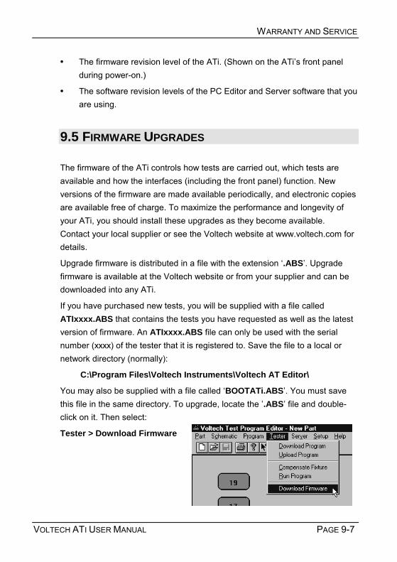
WARRANTY AND SERVICE
VOLTECH ATI USER MANUAL PAGE 9-7
• The firmware revision level of the ATi. (Shown on the ATis front panel during power-on.)
• The software revision levels of the PC Editor and Server software that you are using.
9.5 FIRMWARE UPGRADES
The firmware of the ATi controls how tests are carried out, which tests are available and how the interfaces (including the front panel) function. New versions of the firmware are made available periodically, and electronic copies are available free of charge. To maximize the performance and longevity of your ATi, you should install these upgrades as they become available. Contact your local supplier or see the Voltech website at www.voltech.com for details.
Upgrade firmware is distributed in a file with the extension .ABS. Upgrade firmware is available at the Voltech website or from your supplier and can be downloaded into any ATi.
If you have purchased new tests, you will be supplied with a file called ATIxxxx.ABS that contains the tests you have requested as well as the latest version of firmware. An ATIxxxx.ABS file can only be used with the serial number (xxxx) of the tester that it is registered to. Save the file to a local or network directory (normally):
C:\Program Files\Voltech Instruments\Voltech AT Editor\
You may also be supplied with a file called BOOTATi.ABS. You must save this file in the same directory. To upgrade, locate the .ABS file and double-click on it. Then select:
Tester > Download Firmware

WARRANTY AND SERVICE
PAGE 9-8 ATI USER MANUAL
The firmware upgrade will now commence, and the Editor screen will show a series of dialogue boxes to identify each stage in the process. The download should take approximately 30 minutes.
In the unlikely event that the Editor display shows an ERROR dialogue box before the download is complete, try repeating the entire procedure. Should the error persist, contact your Voltech distributor.
At the end of the download, the tester will reset itself. You may then carry on using your tester as normal, with the benefits offered by the new firmware being available immediately.
If you were supplied with a BOOTATi.ABS’ file, the Editor will now check the boot code version already inside the AT. If the boot code requires upgrading, the Editor will prompt you with a warning that communications must not be disrupted during the 12 minutes that it takes to upgrade the boot code.
WARNING: You must NOT switch off the AT or interrupt the communications during the 12 minutes required for this part of the upgrade.
If the power is removed from the ATi or the communications disrupted in any way during this process, the ATi may be rendered inoperable and require service at a service center.
For optimum performance and reliability, always upgrade the boot code when prompted. If there is a risk that power or communications may be disrupted, you may choose not to upgrade the boot code at this time, but you should do so at the earliest opportunity. The ATi will continue to function without new boot code.
!
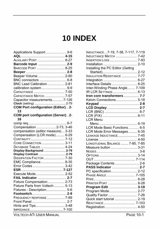
VOLTECH ATI USER MANUAL PAGE 10-1
10 INDEX Applications Support...................... 9-6 AQL ............................................. 4-15 AUXILIARY PORT ............................ 8-27 Barcode Input .............................. 2-9 BARCODE PORT ............................. 8-25 Beeper .......................................... 2-8 Beeper Volume............................ 2-80 BNC connectors ............................ 6-8 BNC Lead Calibration.................. 2-81 calibration system.......................... 9-9 CAPACITANCE ................................ 7-50 CAPACITANCE MATCH..................... 7-57 Capacitor measurements........... 7-126 Clock (setting) ................................2-79 COM Port configuration (Editor)... 2-
13 COM port configuration (Server) .. 2-
16 comp req........................................ 6-7 Compensation ....................2-73, 3-46 compensation (editor measure) ... 3-33 Compensation (LCR mode) ......... 6-29 CONTINUITY................................... 7-12 CORE CONNECTION........................ 3-11 DATABASE TABLES ......................... 4-24 Display Background.......................2-79 Display Contrast ............................2-79 DISSIPATION FACTOR...................... 7-30 EMC Compliance......................... 8-35 Error Codes ................................. 3-42 ESR ........................................... 7-127 Execute Mode.............................. 2-52 FAIL Indicator .............................. 2-7 Fixture Compensation.................. 2-73 Fixture Parts from Voltech ........... 5-13 Fixtures - Description..................... 5-6 Footswitch.................................... 2-9 FREQUENCY RESPONSE .................. 7-89 Front Panel .................................... 2-7 Hints and Tips.............................. 3-48 IMPEDANCE.................................. 7-100
INDUCTANCE...7-19, 7-38, 7-117, 7-119 INDUCTANCE MATCH ...................... 7-42 INSERTION LOSS ............................ 7-93 Installation ................................... 2-10 Installing the PC Editor (Gettng
Started).................................... 2-12 INSULATION RESISTANCE ................ 7-77 Integration ................................... 6-27 Interface Details .......................... 8-25 Inter-Winding Phase Angle........ 7-109 IR LCR SETTINGS ......................... 6-13 Iron core transformers ................ 7-7 Kelvin Connections...................... 5-18 Keypad ......................................... 2-8 LCD Display ................................. 2-7 LCR (BNC) .................................... 6-7 LCR (FIX) .................................... 6-11 LCR Menu
Menu ....................................... 6-19 LCR Mode Basic Functions........... 6-5 LCR Mode Error Messages......... 6-35 LEAKAGE INDUCTANCE.................... 7-45 License........................................ 4-50 LONGITUDINAL BALANCE ........ 7-80, 7-85 Measure button ........................... 3-31 NODES............................................ 3-8 OPTIONS ....................................... 3-14 OUT........................................... 7-114 Package Contents ......................... 2-6 PASS Indicator ............................ 2-7 PC specification........................... 2-12 PHASE ANGLE.............................. 7-105 Print............................................. 6-28 PRINTER PORT .............................. 8-28 Program Edit.............................. 3-19 Program Mode............................. 2-77 Quality Factor .............................. 7-26 Quick start tutorial ....................... 2-19 REACTANCE................................. 7-103 Registration ................................. 4-50

INDEX
PAGE 10-2 ATI USER MANUAL
REMOTE PORT ...............................8-29 RENAMING A TERMINAL .....................3-9 RESISTANCE .........................7-13, 7-34 RESP FREQUENCY RESPONSE ....7-89 RETURN LOSS................................7-96 RUN Indicator...............................2-7 Run-pads ......................................2-9 Schematic - creating ......................3-6 SCREEN CONNECTION ....................3-12 Self-Test ......................................2-49 self-test (during power-on) ...........2-10 Series and parallel circuits .........7-124 Server Hardware connections ..2-14 Server Installation (Getting Started).2-
14 SERVER PORT................................8-27 Service...........................................9-6 SETTINGS ......................................6-21 Signal...........................................6-22 Softkeys........................................2-8 Specification summary...................8-5 STATISTICS
BASIC STATISTICS ...................... 4-14 Stop on Fail ................................. 2-69 Stop On Fail (Editor).................. 3-17 Switching on ................................ 2-10 TANδ............................................. 7-30 terminals ........................................ 3-7 TERMINALS ...................................... 3-8 TEST LIMITS (EDITOR)..................... 3-27 TESTS (ADDING) ............................. 3-21 Tests and test conditions............... 7-4 Trim ............................................. 2-71 TRIM.......................................... 7-112 TURNS RATIO................................. 7-60 TURNS RATIO BY INDUCTANCE......... 7-68 Upgrades....................................... 9-7 USER PORT ................................... 8-31 VOLTAGE OPEN CIRCUIT ................. 7-73 Warranty........................................ 9-5 Weight ......................................... 8-34 winding .......................................... 3-7