managing building moisture - building · pdf filemanaging building moisture ... liquid water...
TRANSCRIPT

Managing BuildingMoisture
�������������������
������������
��������yzz{{|}}~~��
��������
������������yz{||}}~~���

© American Standard Inc. 1998
SYS-AM-15 i
Managing BuildingMoisture
by Dennis Stanke, staff engineerLa Crosse, Wisconsin
Bruce Bradway, senior airside applications engineerLexington, Kentucky
with Art Hallstrom, airside applications engineering managerLexington Kentucky
Nan Bailey, information designerLa Crosse, Wisconsin
Special thanks to: J. David Odom III, vice president CH2M Hill and his staff inOrlando, Florida, for permission to adapt text and illustrations from theCH2M Hill manual �Preventing Indoor Air Quality Problems in Hot,Humid Climates: Design and Construction Guidelines,� © CH2M Hill,1996.

ii © American Standard Inc. 1998
SYS-AM-15
Contents
Preface ......................................................................................................... iv
Introduction ............................................................................................. 1
Good Reasons for Dry Buildings ........................................ 2
Better Indoor Air Quality/Better Health ...................................................... 2Reduced Building System Deterioration ................................................... 3More Comfortable Space Conditions ......................................................... 3
Moisture Sources ............................................................................... 4
Liquid-Water Sources ............................................................................. 4Weather .................................................................................................. 5Ground Water ......................................................................................... 5Interior Leaks .......................................................................................... 6Cleaning ................................................................................................. 6
Water-Vapor Sources ................................................................................... 6Vapor-Pressure Diffusion ........................................................................ 7People .................................................................................................. 10Evaporation .......................................................................................... 10Combustion .......................................................................................... 12Infiltration .............................................................................................. 12Ventilation ............................................................................................. 14
Condensation ............................................................................................. 15
Moisture and Building Envelope ....................................... 17
Prevent Liquid-Water Intrusion ................................................................ 17Minimize Vapor-Pressure Diffusion ......................................................... 17Minimize Infiltration ................................................................................... 18Summary ..................................................................................................... 20
Moisture and Occupied Spaces ......................................... 21
Minimize Liquid-Water Sources ............................................................... 21Prevent Unplanned Condensation ........................................................... 21Dehumidify Spaces .................................................................................... 22
Account for All Loads ............................................................................ 23Part-Load Control ................................................................................. 23Unoccupied Control .............................................................................. 24System Monitoring ................................................................................ 25
Summary ..................................................................................................... 25
© American Standard Inc. 1998
SYS-AM-15 iii
Contents
Equipment-Room Moisture .................................................... 26
Minimize Moisture Sources ...................................................................... 26Prevent Unplanned Condensation ........................................................... 27
Raise Surface Temperature and Vapor Seal ........................................ 27Lower Equipment-Room Dew Point ..................................................... 27
Dehumidify Ventilation Air ........................................................................ 28Equipment-Room Design Examples ........................................................ 30
A Poor Design: Negative Pressurization .............................................. 30A Better Design: Positive Return-Air Pressurization ............................ 32Best Design: Positive Supply-Air Pressurization .................................. 34
Summary ..................................................................................................... 35
Moisture and Chillers ................................................................... 36
Moisture and Air-Handling Units ....................................... 37
Condensate Collection Pans .................................................................... 37Size Coil to Limit Carryover .................................................................. 37Slope to Prevent Standing Water ......................................................... 38Drain to Prevent Flooding ..................................................................... 39
Drain-Line Seals ......................................................................................... 39External Condensation .............................................................................. 41
Seal Penetrations and Joints ................................................................ 42Improve Unit Insulation ......................................................................... 43
Internal Condensation ............................................................................... 45Seal Unit Penetrations and Joints ........................................................ 46Lower Equipment-Room Dew Point ..................................................... 46
In Conclusion ....................................................................................... 47
Acknowledgments ................................................................................ 47

iv © American Standard Inc. 1998
SYS-AM-15
Preface
Uncontrolled moisture within a building can contribute to structural damage,occupant discomfort and unacceptable indoor air quality. Moisture is oftenoverlooked or underestimated during HVAC system design and operation, and itcan cause significant problems in the building envelope, occupied spaces andmechanical-equipment rooms.
This manual helps HVAC system designers identify and quantify moisturesources. It also presents moisture-management techniques related to thebuilding envelope, the occupied space and the mechanical-equipment room.
Moisture problems can occur in buildings in any geographic location. Thesolutions identified in this manual apply to building-moisture management in anyclimate; however, the concepts are especially applicable for buildings located inhumid climates.
The Trane Company, in proposing these system design and applicationconcepts, assumes no responsibility for the performance or desirability of anyresulting system design. System design is the prerogative and responsibility ofthe system designer.

© American Standard Inc. 1998
SYS-AM-15 1
®
Introduction
Uncontrolled moisture in buildings can cause serious problems for buildingoccupants, furnishings and structure. Microbial growth, encouraged by highrelative humidity, leads to poor indoor air quality and building deterioration.
Poor IAQ results in discomfort, health problems and could ultimately lowerproductivity and spawn lawsuits. Uncontrolled moisture can also stain wallsurfaces, damage paint, corrode metal surfaces and accelerate the deteriorationof building furnishings and structural materials. Buildings located in climates withlong periods of high ambient temperature and high, absolute humidity (hot,humid climates) are particularly prone to uncontrolled moisture. Figure 1illustrates �humid climate� and �fringe climate� regions within the U.S.
Figure 1 Hot, Humid Climates
This manual discusses design considerations and HVAC operating techniquesthat help control moisture within occupied buildings once it enters the building. l
© American Standard Inc. 19982 SYS-AM-15
®
Good Reasons forDry Buildings
Controlling building moisture takes time and money. How do buildingoccupants and building owners benefit from these expenditures?
Better Indoor Air Quality/Better HealthBuilding components (walls, floors and ceilings) and building furnishings (wallcoverings, carpets, furniture and stored materials) provide ideal amplificationsites for microbial growth. Microbial growth�fungi, bacteria and dust mites, forinstance�can produce odors, allergens, and in some cases, toxins.
Odors cause discomfort and long-term exposure to allergens and toxins can leadto health problems such as asthma and lung disease. Also, musty-smellingbuildings cannot command high rent or a high resale price.
For microbial growth to occur, certain conditions must be present�w A source of foodw Temperature between 40°F�100°Fw Adequate moisture, usually 70% RH or higherw A source of mold or mildew spores
These conditions can certainly be present in a building. Materials used inbuilding construction, building furnishings, stored materials (books and papers)and accumulated dirt can all become food sources for microbial growth. Typicalindoor temperatures fall in the middle of the microbial growth temperature range.Uncontrolled, indoor relative humidity can easily rise above the 70% RH neededto encourage microbial growth, especially in hot, humid climates. Spores, ofcourse, are present everywhere in both indoor and outdoor air as well as inbuilding materials and furnishings.
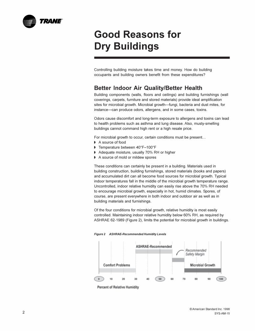
Of the four conditions for microbial growth, relative humidity is most easilycontrolled. Maintaining indoor relative humidity below 60% RH, as required byASHRAE 62-1989 (Figure 2), limits the potential for microbial growth in buildings.
Figure 2 ASHRAE-Recommended Humidity Levels
© American Standard Inc. 1998
SYS-AM-15 3
®
Good Reasons forDry Buildings
Reduced Building System DeteriorationThe same fungi (mold and mildew) that cause people discomfort and/or harmcan also cause building materials, furnishings and structure to prematurelycorrode and/or degenerate. Premature failure of walls, ceilings and floors andirreversible damage to carpets, wall coverings and furnishings can result.
The same rationale holds true for the air handling equipment and duct system.Wet insulation can lead to corrosion and/or deterioration, shortening the usefullife and effectiveness of the air-distribution system.
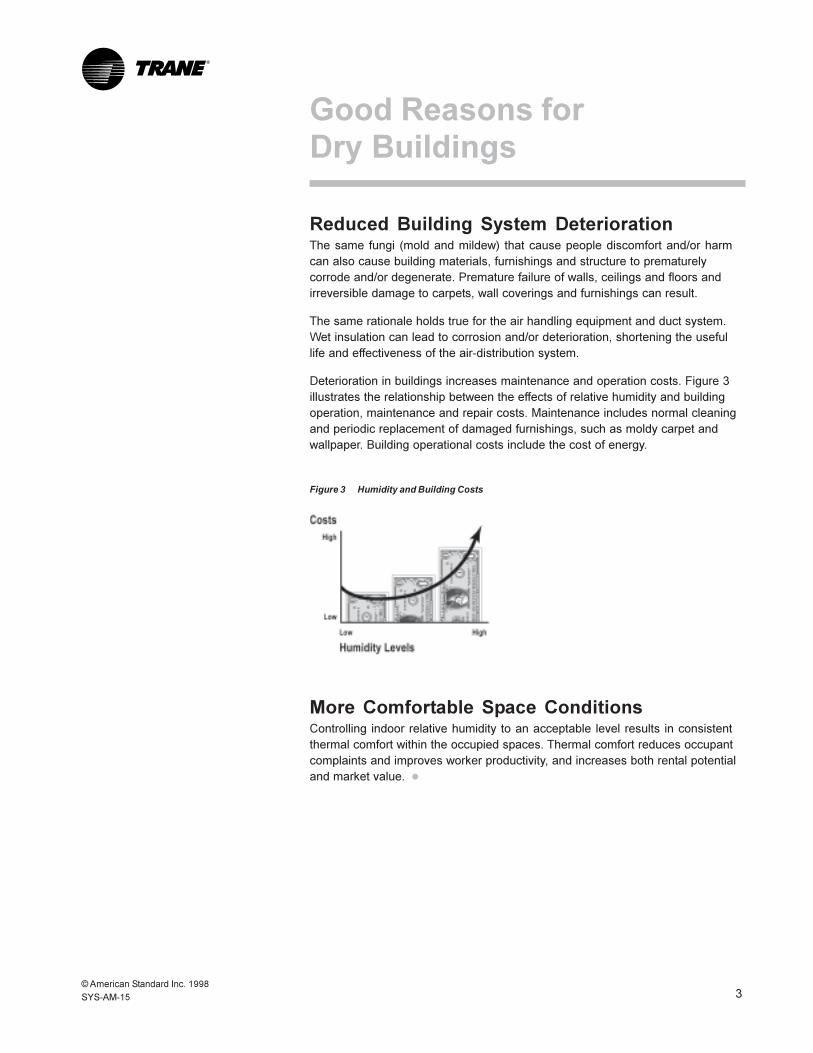
Deterioration in buildings increases maintenance and operation costs. Figure 3illustrates the relationship between the effects of relative humidity and buildingoperation, maintenance and repair costs. Maintenance includes normal cleaningand periodic replacement of damaged furnishings, such as moldy carpet andwallpaper. Building operational costs include the cost of energy.
Figure 3 Humidity and Building Costs
More Comfortable Space ConditionsControlling indoor relative humidity to an acceptable level results in consistentthermal comfort within the occupied spaces. Thermal comfort reduces occupantcomplaints and improves worker productivity, and increases both rental potentialand market value. l

© American Standard Inc. 19984 SYS-AM-15
®
Moisture Sources
Moisture enters the building as liquid water or as water vapor. It causes troublein either form and changes readily from vapor to liquid through condensation. Itmust be properly managed to avoid trouble. Let�s look at possible moisturesources and techniques to minimize the impact of each.
Liquid-Water SourcesLiquid water damages furnishings and building structure, supports microbialgrowth and provides surface wetness for evaporation, a source of water vaporand increased indoor moisture load. Common liquid-water sources include theweather (rain, fog and snow), ground water, leaking pipes and equipment, andwet cleaning processes (see Figure 4). Perhaps the most troublesome source ofliquid water, condensed water vapor, is discussed separately on the followingpages.
Figure 4 Common Liquid-Water Sources in Buildings

© American Standard Inc. 1998
SYS-AM-15 5
®
Moisture Sources
WeatherDuring building construction, prior to completion of the roof and walls, buildingmaterials and the partially completed building structure may become saturatedwith rainwater or snow. Protect building materials from rain, snow andcondensation (which can form inside equipment wrapped with a vapor retardersuch as plastic) during construction. For best results, store materials withincovered structures. If materials become wet, dry them quickly and completely orreplace them. Mold can grow within 24 hours on wet materials. Discard visiblymoldy materials and replace with new, dry materials.
During normal operation, rain may enter the building structure through roof andwall leaks or openings. Design windows and walls to minimize leakage andcontrol water with internal drainage schemes. Roof design and constructionpractices must result in a leakproof membrane that drains properly. Roofs needproper maintenance to assure long-term integrity. Repair leaky walls and roofsquickly to prevent water damage and to avoid high latent loads indoors.
The outdoor intake airflow may entrain rain droplets or snowflakes and carrythem into the duct system. Design outdoor air intakes to limit rainwaterentrainment, using rain hoods and moisture eliminators sized to avoid high intakevelocity. If the design allows water droplets to penetrate the intake, provide forindoor drainage (drain pans for instance); in other words, manage the water flowonce it enters the building.
Rain hoods and moisture eliminators cannot stop entrained snow. Preventpossible filter damage or internal flooding using a heating coil to melt the snow ora large plenum to allow the snow to settle, melt and evaporate before it reachesthe filters.
Fog also enters the building through the outdoor air intake. Fog droplets, toosmall to stop at a louver or moisture eliminator, usually evaporate quickly withinthe HVAC system, causing little or no surface wetting. However, the evaporateddroplets certainly add to the indoor moisture load and must be accounted for inthe design and operation of the system.
Ground WaterGround water may seep into the building through very small cracks in basementwalls and floors. Be sure that surface water and subsurface water drains awayfrom the building, not toward it. Design the floor to limit water intrusion via cracksand joints. Manage any water that penetrates the floor using proper slopes anddrains.
© American Standard Inc. 19986 SYS-AM-15
®
Interior LeaksLeaking appliances, valves and pipes can quickly wet large areas of interiorstructure. Liquid water within walls and concealed areas, through capillary actionand surface tension, can travel long distances and result in widespread, long-term wetting.
Plan and follow maintenance procedures to assure speedy location and repair ofany water leaks within the building. Accidental spills and floods should becleaned up quickly. If porous materials become wet, dry them completely within24 hours or consider replacing them.
CleaningCleaning processes, such as floor mopping and carpet shampooing, result inlarge wet areas. Carpet shampooing in particular increases moisture content incarpet fibers (and in the accumulated dirt beneath the carpet).
Use wet cleaning processes cautiously (or not at all). Take steps to dry wet-cleaned surfaces within 24 hours. For shampooed carpets, assure speedyevaporation by providing adequate air motion and dehumidification during drying.If a cooling coil controlled by a thermostat provides the necessarydehumidification, auxiliary heat may be needed to maintain a sufficient coolingcoil load for continuous dehumidifying capacity.
Water-Vapor SourcesA high indoor water-vapor level elevates the indoor dew point and relativehumidity, and it contributes to the latent load on HVAC equipment. High dewpoint increases the likelihood of unplanned condensation; high relative humiditycan result in occupant discomfort, increased dust mite population, andaccelerated microbial growth. HVAC-equipment capacity must match total (latentplus sensible) load.
Common water-vapor sources in buildings (see Figure 5) include vapor-pressurediffusion from outside, evaporation from people, wet surfaces and processes,generation from combustion, infiltration from outside and introduction fromoutside via ventilation airflow.
Moisture Sources

© American Standard Inc. 1998
SYS-AM-15 7
®
Figure 5 Common Water-Vapor Sources
Vapor-Pressure DiffusionWater vapor moves through solid materials in direct proportion to the differencein vapor pressure between the opposite sides of the material and the resistanceof the material to water-vapor flow (the permeance of the material).
Moisture Sources

© American Standard Inc. 19988 SYS-AM-15
®
The �moisture load� (grains of water per hour) added to a building from outsideby vapor-pressure diffusion can be found using Equation 1.
Equation 1
Wp = P � A � (VPo � VPi)
Where�Wp = moisture load (gr/h)
P = permeance factor (gr/h � ft2 � in. Hg)A = surface area (ft2)
VPo = outdoor vapor pressure (in. Hg)VPi = indoor vapor pressure (in. Hg)
The table below (from 1997 ASHRAE Fundamentals Handbook) showspermeance factors for some common construction materials. The permeancefactor for a composite wall (Pc) can be found as the reciprocal of the sum ofpermeance reciprocals.
Common Construction Materials Permeance*
hardwood siding (1/8") 11.00
air space (1.0") 120.00
polyethylene vapor retarder (0.002") 0.16
insulating board sheathing (1.0") 50.00
fibrous insulation (6.0") 19.00
gypsum wallboard (3/8") 50.00
paint, commercial latex 6.28
vinyl wallpaper 0.23
*Permeance factor = gr/h � ft2 � in. Hg
Consider a composite wall that includes wallboard (P = 50), fibrous insulation(P = 19), exterior sheathing (P = 50), and hardboard siding (P = 11), and has ahigh composite permeance [Pc = 1÷ (1 ÷ 50 + 1 ÷ 19 +1 ÷ 50 + 1 ÷ 11) = 5.448];i.e. water vapor can diffuse through the wall quite readily. The same compositewall with a polyethylene vapor retarder (P = 0.16), has a much lower itscomposite permeance (Pc = 0.155); i.e. water-vapor diffusion through this wall ismuch more difficult.
Moisture Sources
© American Standard Inc. 1998
SYS-AM-15 9
®
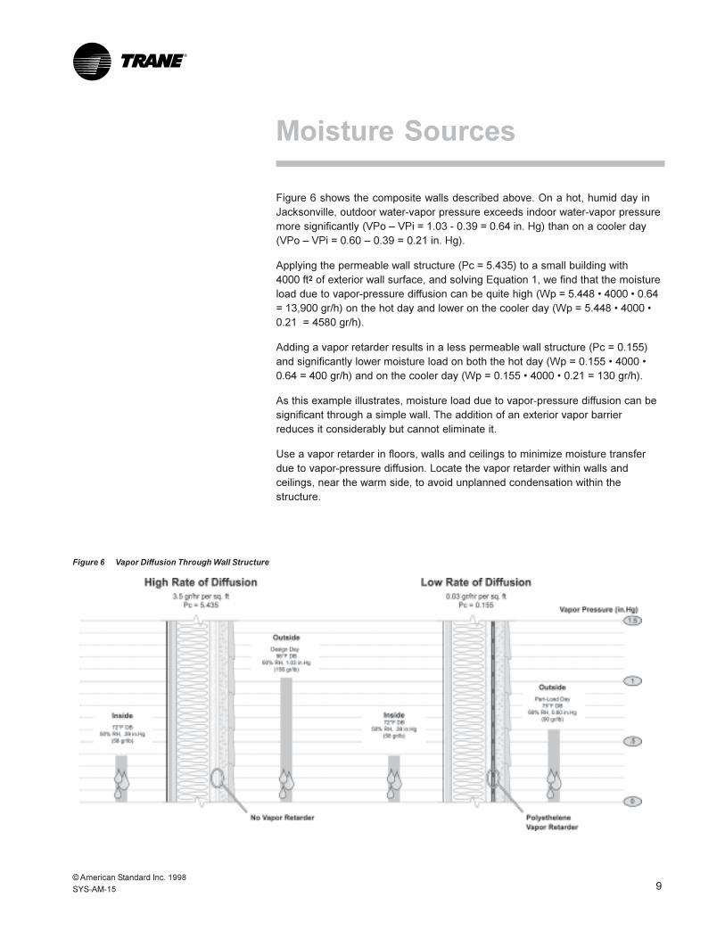
Figure 6 shows the composite walls described above. On a hot, humid day inJacksonville, outdoor water-vapor pressure exceeds indoor water-vapor pressuremore significantly (VPo � VPi = 1.03 - 0.39 = 0.64 in. Hg) than on a cooler day(VPo � VPi = 0.60 � 0.39 = 0.21 in. Hg).
Applying the permeable wall structure (Pc = 5.435) to a small building with4000 ft2 of exterior wall surface, and solving Equation 1, we find that the moistureload due to vapor-pressure diffusion can be quite high (Wp = 5.448 � 4000 � 0.64= 13,900 gr/h) on the hot day and lower on the cooler day (Wp = 5.448 � 4000 �0.21 = 4580 gr/h).
Adding a vapor retarder results in a less permeable wall structure (Pc = 0.155)and significantly lower moisture load on both the hot day (Wp = 0.155 � 4000 �0.64 = 400 gr/h) and on the cooler day (Wp = 0.155 � 4000 � 0.21 = 130 gr/h).
As this example illustrates, moisture load due to vapor-pressure diffusion can besignificant through a simple wall. The addition of an exterior vapor barrierreduces it considerably but cannot eliminate it.
Use a vapor retarder in floors, walls and ceilings to minimize moisture transferdue to vapor-pressure diffusion. Locate the vapor retarder within walls andceilings, near the warm side, to avoid unplanned condensation within thestructure.
Moisture Sources
Figure 6 Vapor Diffusion Through Wall Structure

© American Standard Inc. 199810 SYS-AM-15
®
In humid climates and other predominantly cooling climates, use low-permeance materials near the outside surface (the warm side) to keepsummertime outdoor water vapor away from cold, interior surfaces. When thebuilding includes an attic, be sure to include a continuous vapor retarder on theattic side of the insulation.
In mixed climates, for buildings with low wintertime inside relative humidity(35% RH or less), use low-permeance materials near the outside surface, asrecommended for cooling climates.
In predominantly heating climates, use low-permeance materials near the insidesurface (the warm side) to keep wintertime indoor water vapor away from coldexterior surfaces.
PeopleBuilding occupants produce water vapor at different rates, depending upon theiractivity level, via respiration and perspiration. According to the 1997 ASHRAEFundamentals Handbook, an adult working at a desk introduces a latent load of155 Btu/h, and an active athlete contributes 1000 Btu/h.
Since water vapor contains approximately 0.14 Btu/gr, an office workercontributes 1100 gr/h (Wo = 155 / 0.14) to the indoor moisture load while avolleyball player contributes approximately 7100 gr/h (Wo = 1000 / 0.14).
Although it can be significant, many designers erroneously consider respirationas the sole source of moisture load in buildings. Design the HVAC system andequipment with sufficient capacity to satisfy the total moisture load, including thepeople-related moisture load as one of many sources.
EvaporationWet surfaces add moisture to indoor air through evaporation. Evaporation occurswhen the air vapor pressure (VPa) is less than the vapor pressure of thesaturated air at the wet surface (VPs).
Wet surfaces, found throughout the building, may be planned (pools, aquariumsand fountains) or unplanned (such as leaky pipes and unplanned condensation).Cooking processes and live plants add water vapor via evaporation. On rainy orsnowy days, building occupants carry a significant amount of moisture into thebuilding on their shoes and clothing.
Equation 2 can be used to calculate the moisture load due to evaporation fromliquid-water surfaces.
Moisture Sources

© American Standard Inc. 1998
SYS-AM-15 11
®
Equation 2
We = H � A � (VPs�VPa) � 7000/1060
Where�We = moisture load from evaporation (gr/h)
H = latent heat transfer rate (Btu/h � ft2 � in. Hg, see Figure 7)A = water surface area (ft2)
VPs = saturated vapor pressure of air at the water surfacetemperature (in. Hg)
VPa = vapor pressure of space air (in. Hg)7000 = definition of grains (gr/lb)1060 = latent heat of vaporization at 75°F (Btu/lb)
Figure 7 shows latent heat transfer rate (H) related to air stream velocity. Forexample, a large aquarium in an office with typical 50-fpm transverse airflow(perpendicular to surface) transfers latent heat to the air at a rate of (H = 250Btu/h � ft2 � in. Hg). If the space is 72°F, 50% RH (VPa = 0.39), and 8 ft2 of watersurface at 78°F (VPs = 0.96 in. wg) is exposed, the evaporation moisture loadcan be found using Equation 2 (We = 250 � 8 � 0.57 � 7000 / 1060 = 7500 gr/h).
In another example, a 4-ft diameter puddle (A = 12.5 ft2) of condensate at 80°F(VPs = 1.03) on the floor of an equipment room at 85°F, 50% RH (VPa = 0.60),contributes 8900 gr/h (We = 250 � 12.5 � 0.43 � 7000 / 1060) to the equipmentroom.
Figure 7 Latent Heat Transfer from Water Surface(with respect to the research by W.H. Carrier in 1918)
Moisture Sources
© American Standard Inc. 199812 SYS-AM-15
®
Depending on the situation, moisture load due to evaporation from watersurfaces may be significant. Design the HVAC system with sufficient capacity tosatisfy the moisture load from all sources, including evaporation from plannedwater surfaces (pools and fountains) and predictable liquid-water sources(rainwater in entryways, shampooed carpets). Minimize unplanned evaporationsources (liquid water from leaky pipes, leaky roofs, and spills) by quicklyeliminating the source and removing the liquid water.
CombustionCombustion liberates water vapor. Remember from high-school chemistry: thetwo products of complete combustion are carbon dioxide (CO2) and water (H2O).Equation 3 can be used to calculate the rate of moisture generation from anopen gas flame. Open-flame heaters, boilers and appliances, as well as open-flame cooking surfaces, can produce significant water vapor.
Indoor combustion processes must be considered when calculating indoormoisture load. If an unvented gas griddle consumes natural gas at a known rate(G = 6.7 ft3/h), the combustion moisture load can be easily found (Wc = 6.7 � 650= 4400 gr/h).
Equation 3
Wc = G � KWhere�
Wc = moisture load from combustion (gr/h)G = gas firing rate (ft3/h)K = 650 gr/ft3 for natural gas
1300 gr/ft3 for propane
If possible, use vented combustion processes to eliminate combustion moistureload and other products of combustion. Dehumidify to remove moisture fromunvented combustion processes within the building.
InfiltrationNo building is airtight. Outdoor air enters (infiltration) and indoor air leaves(exfiltration) via countless little openings in the building envelope as well as largeintentional openings such as doors and windows.
Driven by differential pressures imposed by mechanical ventilation, wind andstack effect, the infiltration (exfiltration) air carries water vapor with it. Air passesthrough any available penetration in wall, floor or ceiling.
Moisture Sources

© American Standard Inc. 1998
SYS-AM-15 13
®
Elevator shafts act as chimneys, reducing pressure on lower floors. Gaps canbe found at wall-floor or wall-ceiling joints, between wallboard and electricalfixtures on perimeter walls, at electrical wire and conduit penetrations, at pipeand duct penetrations, and at window and door penetrations. Air also comesand goes through open exterior doorways and windows. Whenever an exteriordoor opens in Florida, cooled indoor air spills out of the building at floor level,only to be replaced by an inflow of warm, moist air at door-top level.
How much water vapor moves with the air? Building moisture load due toinfiltration can be calculated using Equation 4.
Equation 4
Wi = A � r � 60 � Va � (HRo � HRi)Where�
Wi = moisture load due to infiltration (gr/h)A = area of opening (ft2)r = density of outdoor air (lb/ft3)
60 = minutes per hour (m/h)Va = air velocity through opening (fpm)
HRo = outdoor air humidity ratio (gr/lb)HRi = indoor air humidity ratio (gr/lb)
Equation 4 includes air velocity and the total area of all openings in the envelope.Values for these variables may be estimated, either at normal or extremedifferential (inside-to-outside) building pressure. However, it may be morepractical to estimate total envelope airflow (Qe = A � Va) as follows.
Building �tightness� specifications often rate building leakage at a differentialpressure of 0.30 in. wc. At a positive differential pressure of 0.30, the 1997ASHRAE Fundamentals Handbook, Chapter 25, estimates typical exfiltrationairflow per square foot of exterior wall surface for tight, average and leaky walls(Q = 0.10, 0.30 and 0.60 cfm/ft2, respectively).
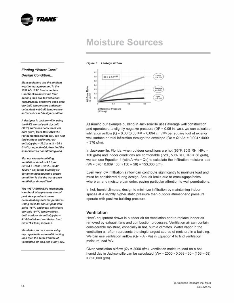
If we assume an exponential relationship between differential pressure andairflow (Q = k � P0.65), established statistically by various researchers, we can findthe flow coefficient (k) for each wall construction category, as shown in Figure 8.
Moisture Sources
© American Standard Inc. 199814 SYS-AM-15
®
Figure 8 Leakage Airflow
Assuming our example building in Jacksonville uses average wall constructionand operates at a slightly negative pressure (DP = 0.05 in. wc.), we can calculateinfiltration airflow (Q = 0.66 (0.05)0.65 = 0.094 cfm/ft2) per square foot of exteriorwall surface or total infiltration through the envelope (Qe = Q � Ae = 0.094 � 4000= 376 cfm).
In Jacksonville, Florida, when outdoor conditions are hot (96°F, 80% RH, HRo =156 gr/lb) and indoor conditions are comfortable (72°F, 50% RH, HRi = 58 gr/lb),we can use Equation 4 (with A �Va = Qe) to calculate the infiltration moisture load(Wi = 376 � 0.069 � 60 � (156 � 58) = 153,000 gr/h).
Even very low infiltration airflow can contribute significantly to moisture load andmust be considered during design. Seal air leaks due to cracks/gaps/holeswhere air and moisture can enter, paying particular attention to wall penetrations.
In hot, humid climates, design to minimize infiltration by maintaining indoorspaces at a slightly higher static pressure than outdoor atmospheric pressure;operate with positive building pressure.
VentilationHVAC equipment draws in outdoor air for ventilation and to replace indoor airremoved by exhaust fans and combustion processes. Ventilation air can containconsiderable moisture, especially in hot, humid climates. Water vapor in theventilation air often represents the single largest source of moisture in a building.We can use ventilation airflow (Qv = A � Va) in Equation 4 to find ventilationmoisture load Wv.
Given ventilation airflow (Qv = 2000 cfm), ventilation moisture load on a hot,humid day in Jacksonville can be calculated (Wv = 2000 � 0.069 � 60 � (156 � 58)= 820,000 gr/h).
Moisture Sources
Finding �Worst Case�
Design Condition�
Most designers use the ambient
weather data presented in the
1997 ASHRAE FundamentalsHandbook to determine total
cooling load due to ventilation.
Traditionally, designers used peak
dry-bulb temperature and mean-
coincident wet-bulb temperature
as �worst-case� design condition.
A designer in Jacksonville, using
the 0.4% annual peak dry bulb
(96°F) and mean coincident wet
bulb (76°F) from 1997 ASHRAE
Fundamentals Handbook, can first
find outdoor and indoor air
enthalpy (ho = 39.2 and hi = 26.4
Btu/lb, respectively), then find the
associated air conditioning load.
For our example building,
ventilation air adds 9.6 tons
(Qt = 4.5 � 2000 � (39.2 � 26.4)/
12000 = 9.6) to the building air
conditioning load at this design
condition. Is this the worst-case
ventilation air load? No!
The 1997 ASHRAE FundamentalsHandbook also presents annual
peak dew point and mean
coincident dry-bulb temperatures.
Using the 0.4% annual-peak dew
point (76°F) and mean coincident
dry-bulb (84°F) temperatures,
both outdoor air enthalpy (ho =
41.6 Btu/lb) and ventilation load
(Qt = 11.4 tons) increase.
Ventilation air on a warm, rainy
day represents more total cooling
load than the same volume of
ventilation air on a hot, sunny day.

© American Standard Inc. 1998
SYS-AM-15 15
®
Contrast the moisture load in Jacksonville to that in Denver. On a typical hot dayin Denver, each pound of ambient air at 93°F, 10% RH contains only 24 grainsof water vapor. Again, given ventilation airflow (Qv = 2000 cfm), ventilationmoisture load can be calculated using Equation 4 (Wv = 2000 � 0.071 � 60 �(24 � 58) = -290,000 gr/h). Note that a negative ventilation moisture load results.In Denver, ventilation air can actually remove moisture from the building ratherthan add it.
Most designers use ambient weather data (see side-bar) to estimate ventilationair conditions and ventilation moisture load. Ambient weather data describeshistorical conditions in a general geographical region. However, local ventilation-air moisture content may be even higher than indicated by ambient conditions.
For instance, a roof-mounted intake in Jacksonville may introduce very warm air(110°F) with very high moisture content (170 gr/lb or more), especially when thesun reappears after a rain shower. Since outdoor airflow cannot be lower thanthe minimum required for proper ventilation, the air introduced for ventilationmust be dehumidified.
Select and operate HVAC equipment and systems to dehumidify the ventilationair at all load conditions.
CondensationCondensate forms whenever moist air contacts a surface at a temperature belowthe dew point (Figure 9).
Figure 9 Surface Condensation
Moisture Sources

© American Standard Inc. 199816 SYS-AM-15
®
Inside the exterior walls, water vapor can enter by vapor-pressure diffusion, byexfiltration or infiltration, or by evaporation from liquid-water leaks�raisinginternal dew point.
In occupied spaces during the cooling season, a supply-air duct or chilled-waterpipe behind an interior wall may cool the wall surface below dew point. Theconcrete beneath carpeted floors may be very cool compared with averagespace temperature. During the heating season, indoor water vapor can easilycondense on cold windows, cold wall surfaces within the space, and inside theexterior wall structure.
The mechanical equipment room offers many cold surfaces for the formation ofunplanned condensate, especially during the cooling season. The outsidesurfaces of air handlers and supply-air ducts, water chillers, chilled-water andreturn-water pipes, and condensate drain pipes all operate at low temperatures.If the equipment room is not conditioned, equipment-room dew point may bevery, very high, especially in hot, humid climates.
Inside the air handler, surface temperature approaches supply air temperature. Ifdesign philosophy results in a high equipment-room dew point, any air leaks intothe air handler downstream of the cooling coil may cause significantcondensation and flooding inside the air handler.
To avoid unplanned condensation in any location, either raise the surfacetemperature or lower the air dew point or both. No other alternative exists.
In summary, many sources of moisture in buildings must be considered. Somecan be eliminated, others can be minimized, but none can be ignored duringbuilding design and operation. l
Moisture Sources

© American Standard Inc. 1998
SYS-AM-15 17
®
Four major building elements must be designed and operated properly tominimize the impact of moisture in the building�w Envelopew Occupied spacesw Equipment roomw HVAC equipment
Let�s start with the building envelope.
Unwanted, unplanned condensate forms inside walls and ceilings if the dewpoint of the internal air exceeds the coldest surface temperature. Since watervapor can enter the wall cavity by evaporation, vapor-pressure diffusion orinfiltration, all three of these potential water-vapor sources must be managed toprevent unplanned condensation.
Prevent Liquid-Water IntrusionWater vapor inside the building envelope structure increases if evaporation fromliquid water occurs. Design and construct exterior walls to keep liquid water out.
Liquid water includes not only rainwater and melted snow, but also ground water,water from leaky pipes and unplanned condensation. Use a water barrier nearthe outside surface of exterior walls to keep the rain and snow out. Design theroof to drain freely and to be watertight. Be sure to drain ground water away fromthe building. Seal all envelope penetrations. Seal underground wall-floor systemsand wall-floor joints.
Minimize Vapor-Pressure DiffusionSince the indoor-to-outdoor temperature difference cannot be controlled,condensation prevention relies on low moisture content (low dew point) within thewalls. In addition to sealing against liquid water, design to limit water-vapordiffusion into the wall�condensation occurs if moist air can penetrate to a coldsurface.
Use a vapor retarder on the warm side. �Warm side� (as mentioned above) incooling and mixed climates means the outdoor side of the ceiling or the wallstructure; in heating climates, it means the indoor side. Do not use two vaporretarders�one on the warm side and one on the cold side. Moisture trappedbetween the two vapor retarders cannot escape and condenses inside the ceilingor the wall at the cold surface. Also, include a sealed vapor retarder in the ceilingof the top floor: in heating climates use a vapor retarder on the space-side, andin cooling climates use one on the attic side.
Moisture andBuilding Envelope

© American Standard Inc. 199818 SYS-AM-15
®
Figure 10 Comparison of Humid Climate Walls
Avoid low-permeance wall finishes (e.g. vinyl wall coverings and latex paint) onperimeter walls and ceilings in cooling climates; condensation and mold growthare commonly found behind perimeter wall coverings in Florida�s buildings.
Minimize InfiltrationSince all air contains water vapor, design the wall structure to limit the movementof moist air into interstitial wall cavities. In cooling and mixed climates, limitinfiltration of outdoor air (the predominant source of moisture) into the buildingstructure using an airflow or weather barrier near the exterior surface ofperimeter walls.
Figure 10 shows both a poor design and a good design for exterior walls incooling or mixed climates. The poor design allows water vapor to penetrate to theinterior wall. The good design limits vapor-pressure diffusion with a warm-sidevapor retarder and outdoor air infiltration with an exterior weather barrier.
Design and operate buildings to assure that indoor static pressure exceedsoutdoor static pressure. Positive building pressure minimizes outdoor infiltrationair, while maximizing �exfiltration� of low-dew-point indoor air into wall cavities.
Moisture andBuilding Envelope

© American Standard Inc. 1998
SYS-AM-15 19
®
Design the building so that the air-handling system can maintain a slightpositive pressure in all portions of the building, including not only the envelopewalls but also the occupied spaces and the equipment room. Positive buildingpressure prevents infiltration due to mechanical system operation (poweredexhaust) and minimizes infiltration due to wind and stack effect. Remember,makeup airflow must always exceed the airflow needed to replace exhaustedair and combustion air (for any open combustion processes) in order tomaintain positive building pressure. Trane Application Manual AM-CON-17provides helpful recommendations related to building pressurization control.
Lower dew point and prevent condensation within the perimeter wall structureby maximizing vapor-pressure diffusion out of the wall while minimizing moistair infiltration into the wall.
As Figure 11 illustrates, without a warm-side vapor retarder, outdoor watervapor diffuses into the wall structure. And, operating the building at a negativepressure, with no exterior air barrier, encourages moist airflow through the walland into the space. On the other hand, using highly permeable materials �on thecold side� and low permeability materials �on the warm side� maximizes vapor-pressure diffusion out of the wall (into the space). Operating with positive buildingpressure and using an external air barrier encourages dry indoor airflow throughthe wall structure to outdoors.
Moisture andBuilding Envelope
Figure 11 Humid Climate Wall Operation
© American Standard Inc. 199820 SYS-AM-15
®
During the winter in heating climates, indoor moisture sources predominate. Itseems logical to operate with negative building pressure to avoid forcing moistindoor air into the walls. However, negative indoor pressure increases theinfiltration of very cold outdoor air, possibly resulting in drafts, cold spots,temperature stratification and discomfort.
Operating with positive indoor pressure, on the other hand, results in exfiltrationof moist indoor air into the perimeter walls. Condensation within the wall structureresults. Very low outdoor-air vapor pressure eventually drives water vapor out forthe wall, but repeated freeze/thaw cycles can cause serious mechanicaldamage, especially within masonry walls.
Proper air distribution plays an important role in uniform building pressurization.Air-distribution systems must be balanced after installation and should bebalanced periodically throughout the life of the building, especially after changesin building use or after system alterations.
SummaryUse water barriers and internal drainage to minimize liquid-water penetration andeliminate water accumulation inside wall structures. Use a vapor retarder on thewarm side of perimeter walls to minimize vapor-pressure diffusion. Do not use avapor retarder (either purposely or accidentally) on the cold side of perimeterwalls. Use an air (weather) barrier on the outside to minimize infiltration due towind and stack effect and liquid-water penetration. Maintain positive buildingpressure in cooling climates to eliminate infiltration due to mechanical systemoperation.
In summary, buildings in humid and predominately cooling climates should bedesigned and operated to be slightly positive. Buildings in heating climates arecomfortable if positive, but may suffer structural damage in winter. Somedesigners and operators maintain slightly positive summertime pressure andslightly negative pressure during transitional seasons and in the winter. l
Moisture andBuilding Envelope

© American Standard Inc. 1998
SYS-AM-15 21
®
Now, let�s turn from the building envelope to the occupied spaces. Theoccupied spaces inside the building should also be designed and operatedproperly to minimize the impact of moisture.
According to ASHRAE 62-89 requirements, relative humidity in occupied spacesshould be maintained below 60% RH at all load conditions. Moisture enters theoccupied space by a number of paths, increasing space dew point, relativehumidity and moisture load. Moisture entry can be minimized, but it cannot bestopped. Therefore, spaces must be designed to minimize moisture load andcontrol relative humidity to 60% RH or less at all load conditions.
Minimize Liquid-Water SourcesUnplanned liquid water within the occupied space can damage furnishings andpromote microbial growth. It also evaporates, adding unplanned moisture load tothe indoor air and raising both dew point and relative humidity.
Design and install window systems that minimize leakage. Keep the windowsclosed during rain showers. As mentioned above, fix leaky pipes or appliancesand dry accidental spills within 24 hours. If possible, avoid carpet shampooing; ifunavoidable, be sure to dry shampooed carpets quickly while maintaining controlof space relative humidity. This might mean adding heat to the space to assureadequate latent cooling capacity while drying.
Prevent Unplanned CondensationWater vapor in the air cannot be eliminated, but keeping space dew point lowerthan space surface temperature can prevent condensation within the space.
Minimize vapor-pressure diffusion using properly placed vapor retarders.Minimize unnecessary wet surfaces (evaporation) within the space. Eliminateunvented combustion processes. To minimize outdoor air infiltration, maintainpositive space pressure in cooling climates and design entryways (using entrytunnels or airlock vestibules) to prevent excessive air-exchange. Do notintroduce untreated outdoor air for space ventilation.
Eliminate cold surfaces. Raise surface temperature by adding heat wherenecessary, or avoid cold-surface/moist-air contact by insulating surfaces frompotential heat sinks and applying a vapor retarder on the warm side. Finally,
Moisture andOccupied Spaces

© American Standard Inc. 199822 SYS-AM-15
®
lower space dew point by removing water vapor. Account for all moisturesources that cannot be eliminated and design the HVAC system with sufficientdehumidification capacity for full-load operation and with proven control schemescapable of maintaining relative humidity below 60% RH at all operatingconditions.
Dehumidify SpacesSince moisture enters the space continuously, it must be removed continuouslyto maintain relative humidity below 60% RH. As Figure 12 illustrates, moisturecan be removed from the occupied space in two ways: direct dehumidificationwithin the space, or by replacing moist return air with dry supply air.
Direct dehumidification, commonly applied in residential basements, simply usesa local dehumidifier�a fan and cold and warm coils in series�to remove watervapor from space air.
Large buildings more commonly use return airflow to physically carry water vaporaway from the space. Air supplied to the space must be dry enough to absorb thewater vapor entering the space�supply air dew point must be low. As localmoisture sources add water vapor to the space, average space dew point can bemaintained by adding sufficiently dry supply air. Space air absorbs the watervapor produced within the space (the latent load) and return air carries it away.
Supply air is commonly dehumidified in one of two ways: by passing it through acold coil or by passing it over a desiccant material, usually mounted on a rotatingwheel. A cold coil dehumidifies as entering-air water vapor condenses on the coilsurface and flows down a drain. A desiccant material dehumidifies as entering-airwater vapor adsorbs onto the desiccant surface and is then rejected to aseparate �regeneration� air stream.
Moisture andOccupied Spaces
Figure 12 Two Space Dehumidification Methods
© American Standard Inc. 1998
SYS-AM-15 23
®
Account for All LoadsHigh, local dew points can occur indoors. Near an exterior door in a Floridaschool, for instance, water vapor enters whenever the door opens, and the doormay open quite often. Local dew point in the entryway rises considerably. Thismoisture, and all locally introduced moisture, must be removed by thedehumidification system. Account for all moisture loads, not just people loads,when designing (sizing) the dehumidification system and the part-load controlsystem.
Select central dehumidification equipment with sufficient capacity to dehumidifyat worst-case conditions. For moisture load, worst-case conditions usually occuron a cool rainy day. The 1997 ASHRAE Fundamentals Handbook now includesvalues for both design-dry-bulb/mean-coincident-wet-bulb and design-dew-point/mean-coincident-dry-bulb to help designers size equipment properly.
Remember that local, ventilation-air moisture content may be even higher thanambient conditions indicate. A sun-baked roof after a rain shower can addsignificantly to moisture load.
Part-Load ControlAn HVAC system sized for the sensible design load usually has sufficientcapacity to adequately remove moisture at both design and part load. However,if not properly controlled at part load, the system may not maintain spaceconditions below 60% RH.
For instance, a 15-ton packaged rooftop, modulated by a thermostat (a sensibletemperature controller), may maintain both sensible temperature and relativehumidity in a classroom very well on a summer day. On a cool, rainy day,however, the thermostat modulates both the sensible and latent capacity of therooftop unit. Although it maintains sensible temperature, the thermostat allowsspace relative humidity to rise unacceptably.
Some HVAC systems, VAV for instance, can provide central dehumidification andcontrol space relative humidity over a wide range of loads without actuallysensing it � space thermostats control temperature by modulating the flow ofvery dry air to the spaces. Other HVAC systems, like the constant-volume rooftopsystem mentioned above, cannot assure indirect relative humidity control.Rather, relative humidity must be sensed to allow active modulation of coolingcapacity for dehumidification as well as sensible temperature control.
Moisture andOccupied Spaces
© American Standard Inc. 199824 SYS-AM-15
®
Systems that deliberately separate space temperature control from spacemoisture control require both a thermostat and a humidistat. A classroom unitventilator, for instance, can use a thermostat to modulate the cooling coil andcontrol sensible temperature and a humidistat to sense relative humidity. If thespace exceeds 60% RH, cooling coil capacity increases to maximum and thethermostat modulates a tempering or �reheat� coil to maintain sensibletemperature.
Note that part-load humidity control with cold coils usually requires supply-airtempering to avoid overcooling the spaces. The boiler or some other source ofheat must be available at part-load operating conditions to add heat to the cool,dry supply air. On the other hand, when using a desiccant-based dehumidifier,the adsorption process heats the supply air; a chiller or some other source ofcooling must be available at all load conditions to remove heat from the warm,dry supply air.
Some central system controls actually reset supply air temperature upward atsensible part-load conditions, often resulting in very poor control of space relativehumidity. Warm supply air contains more moisture than cold supply air. It cannotlower average space relative humidity nearly as well as supply air at designtemperature. Especially in cooling climates, be sure that supply-air-temperature-reset schemes include high-humidity override techniques (return-air humiditysensing, for instance) to limit the amount of reset operation.
Unoccupied ControlDesign and operate to keep indoor spaces dry at all times, not just duringoccupied periods. Monitor building humidity during weekend and night setbackcycles, and automatically operate the dehumidification system to maintain spacehumidity below 60% RH. Unoccupied dehumidification helps limit microbialgrowth and dust mite populations. (Although the people leave the building onweekends, the microorganisms do not!) It also helps avoid long dehumidification�pull-down� times after the unoccupied period. Indoor relative humidity conditionsreturn to �normal� quickly. Carpet, furniture and other porous materials do notstore moisture during unoccupied hours if low vapor pressure is maintained.
Unoccupied dehumidification is particularly important for schools in hot, humidclimates. When the children leave the building at 3:00 p.m., significant watervapor can enter the space via door-opening infiltration. If the dehumidificationsystem turns off at 3:00 p.m. too, space dew point rises and unplannedcondensation can easily occur. Allow continued dehumidification systemoperation after the occupants leave.
Moisture andOccupied Spaces
© American Standard Inc. 1998
SYS-AM-15 25
®
System MonitoringModern building control systems can monitor and log both equipment andspace conditions. Use trend-logging features to monitor changes in spacehumidity, building pressure, outdoor airflow and temperatures throughout thesystem. Observed changes in these variables may be useful when diagnosingperceived or potential building problems. For instance, high relative humiditymight indicate negative building pressurization (a system malfunction),deteriorated window or door seals, open loading-dock doors, pipe or roofleaks, or other equipment failures.
SummaryDesign and operate the HVAC system, especially during periods of partialsensible cooling load, to maintain indoor relative humidity below 60% RH, i.e.pressurize and dehumidify. l
Moisture andOccupied Spaces

© American Standard Inc. 199826 SYS-AM-15
®
In addition to the building envelope and the occupied spaces, proper designand operation of another key building element, the equipment room, must beconsidered.
Many building designers place the building HVAC components together in amechanical equipment room. Some equipment rooms include only chillers,others include only air handling units, while still others include chillers, airhandlers and a variety of other equipment. Regardless of equipment-roomcontents, improper design related to moisture can result in many costlyproblems.
Equipment rusts, wood rots, insulation deteriorates, water pools on the floor andmay invade other parts of the building. Microorganisms bloom, resulting in odors,irritants and further deterioration of materials. To avoid or at least minimize theseproblems, as with the envelope and the occupied spaces, certain basic designprinciples apply.
Minimize Moisture SourcesDo not allow rain or snow to enter the equipment room. Minimize open water. Donot allow condensate from air handlers to run freely across the floor. Fix leakypipes and valves. Design the equipment room to avoid unplanned condensationon cold surfaces.
Minimize unvented combustion appliances or processes within the equipmentroom; combustion generates water vapor. Also, for all combustion processes(vented or unvented), convey makeup air directly from outside to each processusing ducts; do not use the equipment room as a makeup-air plenum forcombustion processes. A negative-pressure equipment room leads to unplannedcondensation.
Minimize vapor-pressure diffusion into the equipment room by insulatingperimeter walls and using a low-permeability vapor retarder on the warm side, asdescribed for the building envelope.
Minimize infiltration due to wind and stack effect. Eliminate infiltration due tomechanical exhaust (or leaky negative return ducts) by pressurizing theequipment room, preferably using dry supply air. Especially in hot, humidclimates, outdoor-air dew point can be extremely high�do not allow untreatedoutdoor air to enter the equipment room, either accidentally or by design.
Equipment-Room Moisture

© American Standard Inc. 1998
SYS-AM-15 27
®
Prevent Unplanned CondensationCondensation occurs whenever air dew point exceeds surface temperature.Design and operate the equipment as appropriate to raise exposed surfacetemperatures and/or lower equipment-room dew point. Remember, the coldsurface location within the equipment room is irrelevant�an air handler with awarm, dry exterior, for example, may generate significant unplannedcondensation on interior airstream surfaces.
Raise Surface Temperature and Vapor SealCold surfaces abound within the equipment room. Some can be heated, butmost must be insulated and vapor-sealed.
For instance, condensate drain pipes, chilled water pipes (both leaving andreturn), even condenser water pipes may contain liquid at temperatures wellbelow room dew point. These pipes must be insulated and sealed with a vaporretarder on the warm side. Water valves and other associated devices must alsobe insulated and vapor-sealed. Insulation alone raises surface temperature, butnot interior temperatures�at some location within the insulation, a cold surfacestill exists. To prevent condensation inside the insulation, vapor-pressurediffusion into the insulation must be minimized using a vapor retarder.
Most equipment-room surfaces can be insulated and vapor-sealed adequately,but some must be heated above dew point. The sections below discuss specificsolutions.
Lower Equipment-Room Dew PointProcess-side temperatures within the equipment room cannot be changed.Supply-air, chilled-water and drain-line condensate temperatures all depend onloads and design criteria, not condensation prevention. To avoid unplannedcondensation throughout the equipment room, lower the equipment-room dewpoint. Insulation can then raise room-side surface temperature above theequipment-room dew point and vapor retarders can keep most moisture awayfrom cold surfaces within the insulation.
Some insulation materials inherently form an effective vapor barrier without theaddition of a separate vapor-retarding material. One square foot of chillerinsulation, for instance, with a permeance factor of 0.30 gr/h � ft2 in. Hg, allowsless than 0.23 gr/h to diffuse into the insulation � more than adequate vapordiffusion protection, provided the joints are well-sealed.
Equipment-Room Moisture

© American Standard Inc. 199828 SYS-AM-15
®
Figure 13 Pressurize to Avoid Condensation
Figure 13 shows a cold condensate drain, first in an unconditioned equipmentroom; then in an equipment room pressurized by a return air fan. In the firstroom, open to outdoor air, a very high dew point results in unplanned condensateformation on the uninsulated-pipe surface. Simply replacing the moisture-ladenoutdoor air in the space with drier return air lowers dew point in the second room.The dew point could have been lowered further using supply air rather thanreturn air to pressurize the room.
Some designers refer to this measure as �conditioning� the equipment room.However, �conditioning� usually implies controlling one or more variables tomaintain a set point. Simply pressurizing the room slightly with either return orsupply air can lower equipment-room dew point significantly. Both sensibletemperature and dew point �float� as supply (or return) air conditions change androom loads vary. No variables are directly controlled, so strictly speaking, theroom is not �conditioned.� �Pressurized� more accurately describes an equipmentroom with low dew point. During construction and normal operation, equipment-room pressurization solves most moisture problems, including internalcondensation. (See side-bar.)
Dehumidify Ventilation AirLet�s examine dehumidification of ventilation air in more detail. Only two air-dehumidification methods need to be considered: desiccant dehumidification andcold-coil dehumidification.
A desiccant dehumidification unit (Figure 14) incorporates a desiccant materialmounted on a rotating wheel. Warm, moist outdoor air enters the rotating wheel.Some portion of the water vapor adsorbs onto the desiccant surface. As therotating wheel turns, the moisture-laden portion moves into the �regeneration� air
Equipment-Room Moisture
During Construction�
Air handlers are often operated at
full capacity (�wild� coils with
very cold, chilled water) providing
cooling and dehumidification for
the construction crew. If the
equipment room is open to
outside, high-dew-point
conditions, and chilled water is
supplied at low-surface, design
temperatures; wet insulation,
internal flooding and general
water damage due to unwanted
condensation often results.
If at all possible, close the
equipment-room envelope prior to
operating the air handler �
properly pressurizing the room to
lower its dew point. Reset the
chilled-water temperature as high
as possible during construction
(i.e., 55°F) to raise equipment-
room surface tempertures.
Don�t allow construction-phase
operation to ruin a well-designed
equipment room before the
building is even finished.

© American Standard Inc. 1998
SYS-AM-15 29
®
Equipment-Room Moisture
stream. Hot air (either heated outdoor air or heated return air) drives theadsorbed water vapor from the desiccant material, drying or �regenerating� it.The wheel rotates the regenerated material into the outdoor air stream again andthe process repeats. Since the hot desiccant raises the temperature of theleaving dehumidified outdoor air, it must be cooled (usually by mechanical and/orevaporative cooling) before it can be delivered to the occupied spaces.
Figure 14 Desiccant Dehumidification
A cold coil dehumidifies simply by presenting a cold surface for controlledcondensation. As warm, moist outdoor air (or a mixture of outdoor andrecirculated return air) passes through the coil, water vapor condenses on thecold coil surface and flows down to the drain pan. Since the cold coil removesheat, the dry supply air may be too cold for the space sensible load; the air mustbe tempered (reheated) to avoid overcooling the occupied spaces.
When using direct refrigerant expansion (DX) to cool the dehumidifying coil,simple sensible-temperature-based cycling for capacity control may lead tohumidity control problems. Coil cycling can lead to wide variations in supply-airdew point and loss of dehumidifying capacity during the �off� cycle. DXdehumidifiers should use a thermostat to control sensible temperature (bycycling coil capacity or by modulating reheat capacity) and a humidistat toactivate full coil capacity when required for proper dehumidification.
Some designers dehumidify the outdoor air before it mixes with recirculatedreturn air in the air-handler mixing section, removing only ventilation moisture.Other designers dehumidify mixed air, removing both ventilation and internallygenerated moisture. Either way, the outdoor moisture load must be removedbefore delivering the ventilation air to the space.

© American Standard Inc. 199830 SYS-AM-15
®
Equipment-Room Design ExamplesEquipment-room designs vary widely. Depending on climate and operation,design decisions may differ. The following examples illustrate poor, better, andbest design practices, especially for equipment rooms in predominantly coolingclimates.
A Poor Design: Negative PressurizationEquipment rooms designed to operate at a negative pressure with respect tooutdoor pressure (unconditioned rooms) commonly encounter unplannedcondensation on all cold surfaces. As a result of infiltration, the dew point simplyrises too high. Avoid designing negative-pressure equipment rooms that use theroom as an intake plenum for outdoor air. Also, avoid other poor, thoughcommon, design practices illustrated in Figure 15.
Key Elements Of Poor Design
Liquid-Water SourcesD Rain water easily penetrates the outdoor air louver.D No trapping allows flooding inside the air handler and leakage onto the floor.D Condensate from drain pan runs across the floor.
Water-Vapor SourcesD Exterior walls with no vapor retarder allow unimpeded flow of water vapor
from outside.D Without an outdoor air duct, the equipment room operates at a negative
pressure to induce ventilation airflow, resulting in significant infiltration.D By design, outdoor air for ventilation enters the equipment room through
louvers in the equipment-room wall, bringing moist outdoor air with it.
Unplanned CondensationD Condensate forms on uninsulated pipes and puddles on the floor.D Condensate forms on the air handler exterior.D Condensate forms on the interior insulation of poorly-sealed supply ducts.D Condensate forms inside the air handler.
Unplanned condensation occurs in a negatively pressurized equipment roomdespite surface insulation and sealing. Any small air leak in air-handling units orducts, or any small break in piping insulation or vapor retarders, results incondensate. Do not design equipment rooms that can become negativelypressurized.
Equipment-Room Moisture

© American Standard Inc. 1998
SYS-AM-15 31
®
Equipment-Room Moisture
Figure 15 Poor Equipment-Room Design

© American Standard Inc. 199832 SYS-AM-15
®
A Better Design: Positive Return-Air PressurizationPressurizing the equipment room goes a long way toward reducing unplannedcondensation. One pressurization technique uses return air dumped into theequipment room by a return fan. This, of course, can only be accomplished insystems that use a return-air fan.
The dew point in such an equipment room roughly matches the return-air dewpoint. Some designers refer to this design as a �conditioned� equipment room,since air returns from conditioned spaces. This level of moisture effectivelyavoids unplanned condensation on external surfaces. However, local moisturesources may still elevate equipment-room dew point to an unacceptably highlevel during many operating hours. Although the �better� design illustrated inFigure 16 resolves some problems, it fails to address others.
Key Elements Of Better Design
Diminished Liquid-Water SourcesC A rain hood protects the intake from rain intrusion.C No open water tanks in the room.D Poor trapping allows flooding inside the air handler and leakage onto the floor.C Condensate drain-line guides condensate to a sanitary drain.
Diminished Water-Vapor SourcesD Exterior walls with no vapor retarder allow unimpeded flow of water vapor
from outside.C Return air fan assures positive room pressure (return-air positive), to
eliminate the infiltration moisture load, but return-air moisture contentcontributes to the equipment-room dew point.
C Ventilation air, ducted directly to unit, adds no equipment-room moisture load.
Unplanned CondensationC Well-insulated, sealed pipes prevent condensation.C Well-insulated air handler limits surface condensation.C Well-sealed supply ducts prevent condensation inside insulation.D Condensate still forms inside the air handler since high-dew-point air can leak
into the unit.
When using powered exhaust or relief fans in the equipment room, duct returnair to the air handler and use the �best� design approach described below. Do notuse the equipment room a negative return plenum. Again, an equipment roomunder negative pressure can be subject to extensive infiltration of untreated,moist outdoor air. Using the return fan to pressurize an equipment roomeliminates outdoor-air infiltration.
Equipment-Room Moisture

© American Standard Inc. 1998
SYS-AM-15 33
®
Equipment-Room Moisture
Figure 16 Better Equipment-Room Design

© American Standard Inc. 199834 SYS-AM-15
®
Best Design: Positive Supply-Air PressurizationAn equipment room pressurized with supply air (supply-air positive) offers thebest solution. Although conditioned by cool, dry supply air, equipment-roomtemperature can �float.� No controls (thermostats or humidistats) are needed tomodulate the pressurizing supply airflow. Dry airflow into the equipment room(see side-bar) limits infiltration and ventilation moisture load by simply filling thespace with low-dew-point air. Therefore, this design avoids the problems ofunplanned condensate formation.
Key Elements Of Best Design
No Liquid-Water SourcesC A rain hood protects the intake from rain intrusion.C Proper trapping prevents internal flooding.C Condensate drain line guides condensate to a sanitary floor drain.
Minimum Water-Vapor SourcesC A vapor retarder on the warm side of exterior walls minimizes moisture load
due to vapor-pressure diffusion from outside.C Low-volume supply airflow assures positive room pressure (supply air
positive), eliminating infiltration moisture load and decreasing equipment-room dew point.
C Ventilation air ducted to the unit adds no moisture load to the equipment room.
No Unplanned CondensationC Well-insulated, sealed pipes prevent condensation.C Well-insulated air handler prevents surface condensation.C Well-sealed supply ducts prevent condensation inside the insulation.C A low equipment-room dew point combined with well-sealed air-handler joints
prevent condensate formation inside the air handler.
The supply airflow needed to pressurize the equipment room varies greatly. Verylow airflow may be enough to maintain sufficient static pressure (0.10 to 0.20in. wc), especially if good, exterior wall construction limits exfiltration throughcracks and openings.
Some designers actually control temperature and/or humidity to truly conditioninterior equipment rooms. However, environmentally controlled equipment roomsmust be designed carefully. Avoid sensible-temperature control schemes thatallow dew point to float. Maintaining sensible temperature cannot assure properdew-point control. Also, remember that a low dry-bulb temperature in the
Equipment-Room Moisture
How Much Air?
Based on wall construction, the
volume of dry supply air needed
to pressurize an equipment room
can be estimated using Figure 8.
Assuming that an �average� wall
and a positive pressure of 0.10
in. wg negates wind effects, we
can estimate leakage [Q = 0.66
(0.10)0.65 = 0.15 cfm/ft2]. If the
exterior wall area is 1800 ft2, the
leakage flow rate is only 270 cfm.
Of course, depending upon
equipment room heat sources,
high dry bulb temperatures may
result. In other words, additional
airflow may be needed to lower
equipment room dry bulb
temperatures to an acceptable
value.

© American Standard Inc. 1998
SYS-AM-15 35
®
equipment room means lower surface temperatures. Ideally, a controlledequipment room would sense and maintain dew point, while maintaining sensibletemperature below a high limit.
SummaryEquipment rooms need special design and operational attention to avoidproblems due to unplanned condensate. Do not use the equipment room as anoutdoor air plenum. Duct outdoor air directly to the air handler.
Consider pressurizing the equipment room with return air if the system uses areturn fan. Better yet, consider pressurizing and dehumidifying the equipmentroom with a small volume of supply air. The simplest, most effective method toresolve all equipment-room condensate problems is to pressurize the equipmentroom with supply air. l
Equipment-Room Moisture
Figure 17 Best Equipment-Room Design

© American Standard Inc. 199836 SYS-AM-15
®
HVAC equipment, both water chillers and air-handling units, must be selected,applied and operated properly with regard to moisture. First, let�s discuss thewater chillers. An operating water chiller develops cold surfaces. Uninsulated orinsulated-but-unsealed chiller surfaces exposed to moist air lead to unplannedcondensate. Chiller condensation problems can be attacked on three fronts:surface heating, surface insulating and sealing, and lowering equipment-roomdew point.
The dew point in a ventilated, unconditioned mechanical room cannot bedecreased; therefore, cold surfaces must be insulated or heated. Some coldsurfaces, valve handles for instance, cannot be insulated. Increased air motionmay add sufficient heat by convection to raise the temperature of a cold chillersurface above surrounding dew point (see Figure 18). In some cases air motionalone is insufficient for very cold spots. A small heater can be used to raisesurface temperature above ambient dew point and prevent condensateformation.
Cold chiller surfaces are often insulated to increase efficiency. Insulation canadequately raise exposed surface temperatures above the dew point of theequipment room, but merely adding insulation between warm, moist air and acold surface cannot prevent condensation.
If significant moisture penetrates (permeates) the insulation, it eventuallyencounters a surface temperature lower than dew point. Without a vaporretarder, moisture permeates the insulation until it encounters a cold enoughtemperature, then condenses. The insulation must be sealed with a low-permeability vapor retarder applied on the warm side. Alternatively, insulationwith low permeability (0.30 gr/h � ft2 � in. Hg), if well sealed, eliminates harmfulcondensation within the insulation.
Of course, lowering equipment-room dew point significantly reduces allunplanned chiller condensation. If possible, pressurize the equipment room withsupply air. l
Figure 18 Raise Surface Temperature
Moisture and Chillers

© American Standard Inc. 1998
SYS-AM-15 37
®
Finally, let�s turn to the air-handling units. Air handling units delivering coolsupply air develop cold surfaces on the cooling coil itself and downstream ofthe cooling coil, both inside and outside of the unit. Exposing these coldsurfaces to moist air can result in unplanned condensation both internally andexternally�situations to be avoided. The cooling coil within the unit produces�planned� condensate�liquid water that must be collected and drained away�as it dehumidifies the entering air. Let�s consider management of the plannedcondensate first, then methods to avoid unplanned condensate.
Condensate Collection PansAs moist air flows through the air handler, condensate forms on the cold-coilsurface and on cold-wall surfaces nearby. It drips into a condensate collectionpan (a drain pan), then drains out of the unit to a sanitary system drain. All airhandlers with dehumidifying coils must include properly designed, installed andmaintained drain pans. Drain pans, along with drain-line seals (usually traps),manage the collected condensate within the unit to avoid unwanted surfacewetting (carryover), standing water and internal flooding.
Size Coil to Limit CarryoverWater droplet carryover from a dehumidifying coil can occur when airflow velocityblows droplets of condensate from the coil surface into the air stream. The drainpan must collect these droplets (Figure 19). Water droplets that fly from the coilsurface to the air handler or duct surface beyond the drain pan become�carryover.� If allowed to accumulate inside the air-handling unit, water fromcarryover results in microbial growth, reduced insulation effectiveness, andinternal flooding. The drain pan must be long enough to catch and collect thecondensate droplets.
Figure 19 Water Droplet Carryover
Moisture andAir-Handling Units

© American Standard Inc. 199838 SYS-AM-15
®
To prevent carryover, do not exceed the maximum allowable coil-face velocity.Coil geometry (fin type, shape and spacing) and allowable face velocitydetermine required drain pan length. Below the velocity limit, water droplets onthe coil surface flow down the coil into the drain pan�the air stream can blowdroplets from the coil, but it cannot carry them beyond the drain pan. Above thevelocity limit, however, the air stream carries water droplets beyond the drain panand deposits it on downstream air-handler and duct surfaces.
Specify coil size to assure that air stream velocity falls below the maximumallowable coil face velocity. Clean the coils regularly: dirty coils cause local high-velocity jets and high-velocity jets lead to carryover beyond the drain pan. Re-evaluate coil performance if airflow requirements change. Increased airflowacross the coil face may increase face velocity above the carryover limit. Consultmanufacturer�s literature for maximum coil-face velocity limits.
Slope to Prevent Standing WaterCollected condensate must not be allowed to accumulate in the air-handler drainpan. Standing water results in microbial growth (microbial slime). The drain panmust be properly sloped and properly connected to a drain system to assurespeedy, complete drainage with the fan on or off.
Design or specify drain pans that slope in two planes, as shown in Figure 20. Aflat pan retains water. A single-plane sloped pan with one drain connection limitsthe volume of water retained; some water �hangs up� in the low corners. A dual-plane sloped pan assures that all water drains out. Be sure to place the drainconnection at lowest point of the pan. Even a very small slope assures completedrainage when the pan slopes in two planes. Remember, proper drain pan slopedepends not only on design but also on installation: the unit must be level. Besure to install the air-handling unit according to the manufacturer�srecommended instructions and within the tolerance specified for levelness.
Moisture andAir-Handling Units
Figure 20 Drain Pan Designs
© American Standard Inc. 1998
SYS-AM-15 39
®
Drain to Prevent FloodingIf collected condensate cannot drain through the drain connection, it spills overthe top of the drain pan and floods the air-handling unit and duct system.Microbial growth as well as equipment and building damage can result frominternal flooding. Proper condensate drainage depends on drain-pan slope,drain-connection size and maintenance, and, as explained below, drain-sealdesign and maintenance.
Condensate forms at a high rate when very moist air enters the coil (as much as5 gpm on a 100-ft2 coil). To assure speedy drainage without drain-pan overflow,do not reduce the drain-pipe diameter to be smaller than the drain connectionprovided by the manufacturer. The equipment manufacturer selects the drainconnection size to accommodate the maximum condensate flow at extremeconditions. Reducing its diameter may result in slower drainage and drain-panoverflow.
Wet coils help clean particles from the air stream. Condensate flow keeps thecoils relatively clean, but dirt accumulates in the drain pan. Accumulated dirtincreases the likelihood of restricted or blocked condensate flow and subsequentflooding. Be sure to inspect drain pans on a regular basis and clean if necessary.
Drain-Line SealsAfter collecting in the drain pan, condensate exits the air handler via the drainconnection, passes through a drain seal, then follows the drain line to a sanitaryfloor drain. Faulty drain seals result in more moisture-related problems than anyother air handler element. Improper design, installation or maintenance of thedrain seal can cause water droplet carryover or internal flooding within the air-handling unit. Although some designers use other sealing devices, simpleP-traps seal the vast majority of air-handler drain pans.
Moisture andAir-Handling Units

© American Standard Inc. 199840 SYS-AM-15
®
Figure 21 Blow-Thru Trapping
Blow-thru designs positively pressurize the drain-pan surface with respect to theequipment room (Figure 21). Supply air �pushes� condensate through the trap,eliminating any concern for water droplet carryover due to trap operation, butraising a concern for maintaining the internal-to-external air seal. Without an airseal, supply air can flow out of the unit into the equipment room, creating a smallsupply-air leak. Inadequate trap depth (D) allows casing pressure to force allwater out of the trap � destroying the seal.
Specify a trap depth no less than the casing static pressure (CP) plus a safetymargin to allow for final, as-installed balancing (D = d + CP + 1 in. wg). Specify atotal trap height (T) no less than the trap depth plus an installation safety margin(T = D + 1 in. wg).
Moisture andAir-Handling Units
Figure 22 Draw-Thru Trapping

© American Standard Inc. 1998
SYS-AM-15 41
®
Draw-thru designs negatively pressurize the drain-pan surface (Figure 22).Equipment-room air �pushes� condensate through the trap toward the drain pan.With insufficient total trap height (T), the trap contains adequate water tomaintain the air seal but not enough to allow water flow. Consequently, the drainpan overflows and floods the inside of the air handler. With insufficient trap depth(D), equipment-room pressure pushes trap water into the drain pan. High velocityair flows into the drain pan throwing water droplets into the supply air stream,causing carryover, due to trap �spitting� or �geysering.� Also, the high-velocityairflow prevents water flow through the drain opening, causing drain-pan overflowand internal flooding.
Each time the draw-thru fan starts, the trap must be �primed� (contain water).Without a water seal, a properly designed trap operates as though it hasinsufficient trap depth: it spits and causes internal flooding. Specify the trap head(H) no less than the negative casing pressure (CP) plus a 1 in. wg safety margin(H= 1+CP). Specify trap depth (D) no less than half the trap head (D = ½ H + d).Total trap height (T) is the sum of installed head and depth (T = H+D). Inspecttraps regularly and prime when necessary, especially just before the coolingseason begins.
Moisture andAir-Handling Units
Plan for proper trapping: the unit must be mounted high enough above the floorto allow for the recommended total trap height (T) and trap depth (D). Countlessair-handler installations include crudely chopped holes in concrete floors; propertrap dimensions were considered as an afterthought, after flooding or carryoverproblems resulted in service expense and building damage. Follow the trapdesign guidelines discussed above.
Remember, even a well-designed trap, if plugged, causes drain-pan overflow andinternal flooding. Inspect traps regularly. Clean and prime if necessary. Do not�gang� drain pans at different surface pressures on the same trap. Use shutoffvalues, not traps, to seal maintenance-only drains.
External CondensationSupply air downstream of the cooling coil and in the supply ducts can be verycold. The coil itself can be even colder; chilled-water temperature may be 45°F orlower. Therefore, external air-handler surfaces and supply-duct surfacetemperatures may also be very low unless adequately insulated. If high dewpoint air can contact these cold surfaces, unplanned external condensation(sweating) occurs, leading to equipment-room flooding, unit discoloration anddamage (corrosion and deterioration), possible building damage, and increasedpotential for microbial growth.

© American Standard Inc. 199842 SYS-AM-15
®
Seal Penetrations and JointsA supply air leak from the air-handling unit or supply duct causes a very coldlocal surface, a �cold spot.� In a high-dew-point equipment room (negativepressure, unconditioned), water vapor from the air condenses readily at the coldspot. Unplanned, liquid water results. Design the pressurized sections of the airhandler and the supply ducts to minimize leakage of cold supply air.
Each penetration of the air handler represents a potential supply air leak. Specifyairtight seals (Figure 23) at all air handler penetration points, including pipepenetrations at the coils (both heating and cooling), unused maintenance-onlydrain openings, and any penetrations for electrical wiring.
Figure 23 Seal Pipe Penetrations
All air-handling units include access doors and panels. Poorly sealed doors andpanels result in supply air leakage. Some units use individual sections, joined atthe factory or in the field, to form the air handler. Each joint downstream of thefan represents a potential supply air leak.
Gasket all access panels, door openings and inspection windows in positive-pressure sections. Seal all joints between sections (Figure 24). Note that draw-thru air handlers usually include fewer pressurized sections than blow-thruconfigurations, so fewer joints need sealing to limit supply air leakage.
Moisture andAir-Handling Units

© American Standard Inc. 1998
SYS-AM-15 43
®
Figure 24 Seal Panel Leaks
Improve Unit InsulationAir-handling equipment typically delivers cool supply air. To prevent heat gainand to avoid surfaces below dew point, the low-temperature air inside theequipment and ducts must be insulated from the warmer surrounding air. All airhandler walls and supply duct walls must be insulated either internally orexternally. The required insulating value for unit and duct walls varies, dependingon equipment-room temperatures (both dry bulb and dew point) and supply-airtemperature (dry bulb).
Positive-pressure equipment rooms designed to maintain a low dew point cantolerate quite cold surfaces without condensation. On the other hand, moisturecondenses readily from high-dew-point air in unconditioned (negative-pressure)equipment rooms so better overall insulation must be used in air handlers andducts.
Moisture andAir-Handling Units
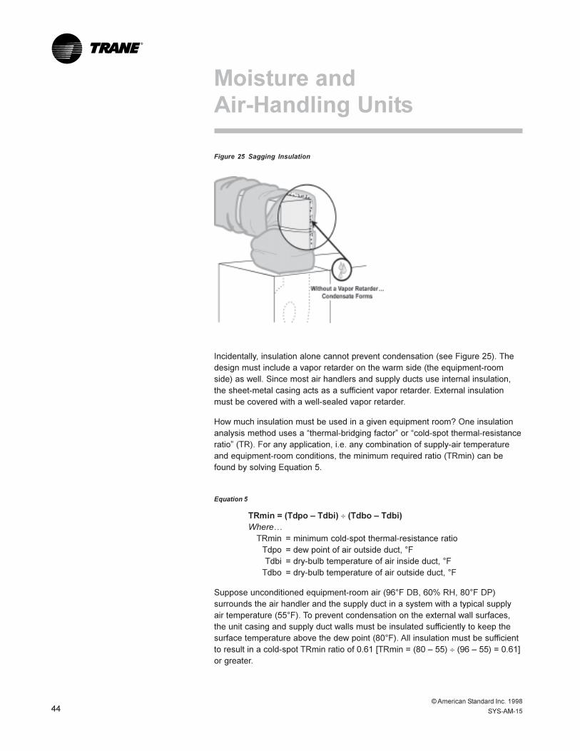
© American Standard Inc. 199844 SYS-AM-15
®
Figure 25 Sagging Insulation
Incidentally, insulation alone cannot prevent condensation (see Figure 25). Thedesign must include a vapor retarder on the warm side (the equipment-roomside) as well. Since most air handlers and supply ducts use internal insulation,the sheet-metal casing acts as a sufficient vapor retarder. External insulationmust be covered with a well-sealed vapor retarder.
How much insulation must be used in a given equipment room? One insulationanalysis method uses a �thermal-bridging factor� or �cold-spot thermal-resistanceratio� (TR). For any application, i.e. any combination of supply-air temperatureand equipment-room conditions, the minimum required ratio (TRmin) can befound by solving Equation 5.
Equation 5
TRmin = (Tdpo � Tdbi) ¸ (Tdbo � Tdbi)Where�
TRmin = minimum cold-spot thermal-resistance ratioTdpo = dew point of air outside duct, °FTdbi = dry-bulb temperature of air inside duct, °F
Tdbo = dry-bulb temperature of air outside duct, °F
Suppose unconditioned equipment-room air (96°F DB, 60% RH, 80°F DP)surrounds the air handler and the supply duct in a system with a typical supplyair temperature (55°F). To prevent condensation on the external wall surfaces,the unit casing and supply duct walls must be insulated sufficiently to keep thesurface temperature above the dew point (80°F). All insulation must be sufficientto result in a cold-spot TRmin ratio of 0.61 [TRmin = (80 � 55) ¸ (96 � 55) = 0.61]or greater.
Moisture andAir-Handling Units

© American Standard Inc. 1998
SYS-AM-15 45
®
Cold-spot TRmin ratios for ducts and air handlers can be determinedexperimentally by measuring the coldest surface (the cold spot) on theequipment at steady-state thermal conditions and solving Equation 6.
Equation 6
TRequip = (Tsurf � Tdbi) ¸ (Tdbo � Tdbi)Where�TRequip = equipment cold-spot thermal-resistance ratio
Tsurf = cold-spot surface temperature, °F
A very-well-insulated air handler with a high thermal-resistance ratio (TRequip =0.70, for instance) could be used in the equipment room above without externalcondensation. However, equipment insulation systems more commonly result inlower thermal-resistance ratio values (TRequip = 0.50, for instance). To use thisequipment without condensate, the equipment-room dew point must be below75°F [Tdpo = (Tdbo � Tdbi) TRequip + Tdbi = (96 � 55) 0.50 + 55 = 75] orapproximately 50% RH.
To assure adequate equipment TR, designers must either specify sufficientinsulation to raise all surfaces, including cold spots, above equipment-room dewpoint, or design low-dew-point (positive-pressure) equipment rooms.
Internal CondensationInternal air-handler surfaces downstream of the cooling coil are cold. If high-dew-point air can contact these surfaces, unplanned condensation inside the unitoccurs. Internal unplanned condensation can result in internal flooding andultimately, reduced insulation effect, unit damage (corrosion and deterioration ofgaskets and adhesives), possible duct and building damage, and increasedpotential for microbial growth.
Figure 26 Internal Condensation
Moisture andAir-Handling Units

© American Standard Inc. 199846 SYS-AM-15
®
Seal Unit Penetrations and JointsSince equipment-room air may be moist (negative-pressure, unconditionedrooms), infiltration of equipment-room air into the air-handling unit must beminimized downstream of the cooling coil.
Blow-thru air handler configurations pressurize the cold sections, eliminatinginfiltration of moist air. However, blow-thru configurations result in anotherinternal moisture problem�fog formation at the coil exit. The small waterdroplets that constitute fog can seriously �wet� downstream surfaces, especiallyfinal filters. Also, high local velocities in a blow-thru coil increase the potential formoisture carryover. Blow-thru units must be applied cautiously or they may causemore moisture-related trouble than draw-thru units.
To limit infiltration into cold sections of the draw-thru units, reduce moist airleakage through the wall. Specify sealing at all air-handler penetration points,including pipe penetrations at the coils (both heating and cooling), unusedmaintenance-only drain openings, and any penetrations for electrical wiring. Sealor gasket all joints, panels, doors and windows in negatively pressurized coldsections.
Lower Equipment-Room Dew PointAs mentioned in the preceding �equipment room� section, lowering the moisturecontent in the equipment room below internal air handler surface temperatureseliminates all internal condensation problems discussed here, regardless of air-handler �skin� integrity.
Leaky air-handling units in supply-air positive equipment rooms do not sufferfrom internal condensate problems. On the other hand, even well-sealed draw-thru units can exhibit internal flooding and �cold tracking� problems in high-moisture-content equipment rooms.
Three simple solutions, properly applied, resolve most air-handler condensateproblems: use dual-slope drain pans, design and maintain the drain trapproperly, and pressurize the equipment room with supply air to lower the dewpoint. l
Moisture andAir-Handling Units
© American Standard Inc. 1998
SYS-AM-15 47
®
In Conclusion
Many moisture-related problems in buildings can be avoided using one simpledesign solution: pressurize with sufficiently dry air.
Properly applied, this simple solution eliminates infiltration moisture load andaccommodates all space-generated moisture loads as well as the ventilationmoisture load. It eliminates condensation within the building envelope and bothinternal and external condensation on HVAC equipment. Coupled with properdesign of all partitions (i.e. insulate and vapor-seal the warm side), proper controlof space relative humidity at part load, and proper drain pan trapping,pressurizing with dry air �evaporates� most moisture problems � even in themost humid of climates.
AcknowledgmentsRefer to �Preventing Indoor Air Quality Problems in Hot, Humid Climates: Designand Construction Guidelines,� prepared by CH2M-Hill. In cooperation with theDisney Development Company, the practices described in this manual havebeen used successfully since 1990 in construction projects valued at over $750million with no significant moisture-related problems. l

Worldwide Applied Systems GroupThe Trane CompanyNorth American Group3600 Pammel Creek RoadLa Crosse, Wisconsin 54601-7599www.trane.com
An American Standard Company
Printed on recycled paper as part ofThe Trane Company’s recycling program.
Since The Trane Company has a policy of continuousproduct improvement, it reserves the right to changedesign and specification without notice.
SYS-AM-15NEWSeptember 1998