managing architectural design decisions for safety ... architectural design decisions for...
TRANSCRIPT
Managing Architectural Design Decisions for Safety-Critical Software Systems
Weihang Wu, Tim Kelly
Department of Computer Science, University of York, York YO10 5DD {Weihang.Wu, Tim.Kelly}@cs.york.ac.uk
Abstract. In this paper, we propose a negative scenario framework along with a mitigation action model as the linkage between safety quality attribute and ar-chitecture definition. The scenario framework provides an effective means of formulating safety concerns. The mitigation action model facilitates exploita-tion and codification of existing safety-critical system design knowledge. Fi-nally, we present a series of steps that enable the justification of architectural design decisions that refine both requirements and architectures. We demon-strate and discuss the application of our framework by means of a case study.
1 Introduction
Over the last decade, the importance of quality requirements (characterised by quality attributes) has been well recognised in architectural design. Recently, the SEI1 has es-tablished a design methodology termed Attributed-Driven Design (ADD) [6] to em-phasise the active role of quality attributes (QAs) in architecture design. Quality at-tributes can be achieved by a set of design options ranging from coarse-grained design patterns to more finer-grained design techniques. The success of the design of an ar-chitecture thus lies with judicious decisions made when selecting the appropriate de-sign options and composing the selected options into the architecture. Among quality attributes, a great significance has been given to software risks in the safety-critical system domain. Examples of the most serious computer-related accidents in the past 20 years such as Therac-25 [12] and Ariane 5 [13] can be attributed to flawed system and software architectures. However, existing practice fails to systematise architec-tural design approaches to addressing these safety concerns.
In this paper, we examine the factors involved in making the principled choices within a safety-related architectural design space and present an approach to rational-ising the architectural decisions behind the selection and the impacts on both require-ments specification and architectural modelling. The paper is organised in the follow-ing sections. Section 2 introduces the key concept of the “safety” quality attribute and existing practice in architectural design for safety. Section 3 presents our framework for decision making. Section 4 demonstrates this framework by means of a case study. Section 5 discusses preliminary findings and related work. Finally, section 6 presents concluding remarks.
1 Software Engineering Institute at Carnegie Mellon University
2 Safety and Architecture
Safety is freedom from accidents or losses; software safety implies the contribution of software to safety in its system context [12]. The remainder of this section analyses the concept of safety as a quality attribute in terms of its underlying concerns and dis-cusses existing solutions and their limitations.
2.1 Safety as a Quality Attribute
Like security, at the heart of defining the safety attribute is the identification and evaluation of negative requirements such as unwanted or unplanned events and condi-tions. Typically, the safety lifecycle [2] starts by identifying negative requirements over existing system-level context. Safety requirements are then derived by choosing appropriate mitigation mechanisms to protect against the negative requirements iden-tified. These safety requirements will in turn act as the constraints on the system and software design. Chosen mitigations may themselves bring new safety problems. New mitigations may thus need to be identified and safety requirements refined. The prob-lem is complicated by the fact that the details of the system are often unavailable until the late stages of development. Hence, a key question is how to elicit and formulate the negative requirements along with the corresponding mitigation mechanisms in co-ordination with the architectural design process in an evolutionary manner.
Another vital aspect of safety is risk. From an engineering standpoint, there is no such thing as absolute safety. Safety is often defined as the measure of the degree of the freedom of risk under all conditions [12]. The basic tenet of evaluating safety-critical systems is thus to ensure that these systems present an acceptable level of risk balanced with their cost. Therefore, an important question is how to integrate risk as-sessment and cost benefit analysis with the safety design process.
Finally, safety is an emergent system property and it is not possible to take a single system component such as a software module in isolation to assess its safety. In prac-tice, the emergent safety properties are enforced by a set of safety constraints upon the architecture. At the top level of design, these safety constraints are imposed upon the whole system (i.e., the system under design and its environment) and often expressed in an absolute functional form (e.g., ‘must’ or ‘must not’). As the design process pro-gresses, the safety constraints are eventually refined into other quality requirements such as performance and availability targets allocated onto the behaviours of relevant architectural components. Inevitably, our concern is thus how to capture such a link-age between safety and non-safety qualities.
2.2 Design for Safety
A large number of design techniques for safety have emerged in both research and practice. Safety is thus achieved by deciding upon the appropriate design techniques to be employed in a specific system context. In general, current practice advocates two classes of design approaches:
• Process-based approaches. Industrial safety standards such as IEC 61508 [2] prescribe a set of safety design techniques with respect to the classification of safety criticality. However, there is lack of practical guidance on demonstrating further how to exploit these techniques to tackle specific safety concerns. More-over, most standards such as ARP 4761 [1] and IEC 61508 dictate the allocation of safety functions over software and hardware but fail to explore the cost/benefit tradeoffs behind allocation decisions.
• Architectural patterns. Architectural patterns have recently influenced the devel-opment of dependable systems. Examples of safety patterns can be found in Douglass’ work [9]. Yet the coarse-grained nature of design patterns makes it dif-ficult to reason precisely about the achievement of desired safety properties and the design tradeoffs involved [18].
Many advances have been made in the theory and principles of system and software safety, yet existing practice in architectural design for safety still remains ad hoc. We argue that this is due to lack of principled basis for choosing appropriate protection mechanisms and poor integration of system development process with the safety life-cycle. The work outlined in this paper follows by our previous work on safety tactics [18] and refines it by exploring the inter-dependencies between safety requirements, safety-related design decisions and architectures. In order for this approach to be suc-cessful, the following four challenges must be addressed: • What is the precise meaning of safety concerns and mitigation approaches? • How can you discover and evaluate these safety concerns with the aid of safety
assessment activities? • How can you identify and select mitigation approaches with respect to the safety
concerns identified and tradeoffs involved? • How do you compose the mitigation approaches selected into both the require-
ments specification and the architecture?
3 Proposed Framework
The aim of this framework is to provide practical guidance on identifying plausible architectural decisions and justifying the decisions made in an iterative and incre-mental manner. There are two important assumptions in the proposed approach. Firstly, our process assumes implicitly parallel development of requirements and ar-chitectures, as recognised by the Twin Peaks model [14]. Another assumption is the co-design of system and software architectures by means of architectural views. From the perspective of embedded system development, we argue that both the system and software architectures are key to realising dependability requirements. System archi-tecture provides the system-level context from which the software architecture is built. Moreover, unifying the design of system and software architectures can effec-tively facilitate safety tradeoffs across the software/system boundaries. For example, system architecture may be designed to mitigate faults emerging from software archi-tecture, and vice versa. The notion of architectural views provides an effective mechanism to restrict our attention on a selected portion of the system or software ar-
chitecture. Views can be grouped in terms of architectural characteristics. Clements et al [6] define three common sets of views: module views, component & connector (C&C) views, and allocation views. Other common classifications can be logical and physical views [8], and Kruchten’s 4+1 views [11]. The number of views needed is driven by the needs or concerns of stakeholders; architects are free to choose the views if applicable. The remainder of this section explains the key concepts in our ap-proach and how they are organised in a decision-driven design process.
3.1 Conceptual Model
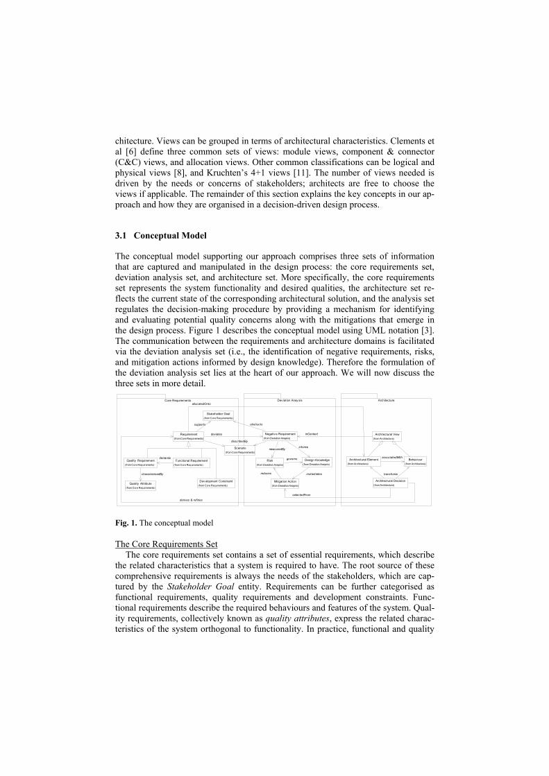
The conceptual model supporting our approach comprises three sets of information that are captured and manipulated in the design process: the core requirements set, deviation analysis set, and architecture set. More specifically, the core requirements set represents the system functionality and desired qualities, the architecture set re-flects the current state of the corresponding architectural solution, and the analysis set regulates the decision-making procedure by providing a mechanism for identifying and evaluating potential quality concerns along with the mitigations that emerge in the design process. Figure 1 describes the conceptual model using UML notation [3]. The communication between the requirements and architecture domains is facilitated via the deviation analysis set (i.e., the identification of negative requirements, risks, and mitigation actions informed by design knowledge). Therefore the formulation of the deviation analysis set lies at the heart of our approach. We will now discuss the three sets in more detail.
Quality Attribute(from Core Requirements)
Functional Requirement(from Core Requirements)
Quality Requirement(from Core Requirements)
characterisedBy
demands
Core Requirements Dev iation Anay sis Architecture
Architectural Element(from Architecture)
Behav iour(from Architecture)
associatedWith
Architectural Decision(from Architecture)
transforms
Mitigation Action(from Deviation Anaysis)
selectedFrom
Architectural View(from Architecture)
Risk(from Deviation Anaysis)
reduces
Design Knowledge(from Deviation Anaysis)
instantiates
governs
Stakeholder Goal(from Core Requirements)
Dev elopment Constraint(from Core Requirements)
Requirement(from Core Requirements)
allocatedOnto
derives & refines
supports
Negativ e Requirement(from Deviation Anaysis)
deviates inContext
measuredByinforms
obstructs
Scenario(from Core Requirements)
describedBy
Fig. 1. The conceptual model
The Core Requirements Set The core requirements set contains a set of essential requirements, which describe
the related characteristics that a system is required to have. The root source of these comprehensive requirements is always the needs of the stakeholders, which are cap-tured by the Stakeholder Goal entity. Requirements can be further categorised as functional requirements, quality requirements and development constraints. Func-tional requirements describe the required behaviours and features of the system. Qual-ity requirements, collectively known as quality attributes, express the related charac-teristics of the system orthogonal to functionality. In practice, functional and quality
requirements must exist together, as shown in Figure 1 by their participation in the demands relationship. Development constraints such as cost and resource budgets are system characteristics that will limit the whole system development choices available when attempting to meet the functional and quality requirements.
One valuable way of articulating functional and quality requirements is the use of scenarios (e.g., use cases [11] and SEI’s quality-attribute-scenario framework [6] re-spectively). A scenario is simply a perceived story of the usage of a system under specific situations. Finally, the derives & refines relationship expresses the fact that requirements are often first stated in a general and abstract form, then restated in more detail as the design process progresses. This relationship explicitly links the require-ments derived through design decisions made in the architecture set. The Architecture Set
Within the architecture set, the system and software architectures are represented by a number of architectural views, each having a coherent collection of architectural elements with associated behaviours. While the views chosen and level of detail of a system may vary, at a minimum, the architecture set serves as a repository for archi-tectural decisions made that will transform an abstract and provisional design solution into an intermediate solution and eventually into a detailed and stable solution. The transformation caused by architectural decisions can exist in the following two ways: • The addition or removal of specific architectural elements (a.k.a., decomposition
decisions) • Reallocation responsibilities over existing architectural elements (a.k.a, allocation
decisions)
As described in section 1, architectural decisions are decisions regarding design op-tions identified in the deviation set. Negative Requirements & Risks
Negative requirements have long been interest to the dependability community. Proper interpretation of negative requirements is critical to proper architectural solu-tions. In contrast with (positive) requirements, negative requirements describe the re-lated characteristics that the system is not allowed to have, which otherwise together with specific conditions in the environment of the system will inevitably lead to the inability of the system to fulfil (positive) requirements, thereby obstructing the plan of achieving the stakeholders’ goals. At an architectural level, the most significant classes of negative requirements are those leading to inability to fulfil the quality re-quirements, which we explicitly label anti-quality requirements. Example of anti-quality requirements can be system hazards (with respect to safety), system vulner-abilities (with respect to security), or bottlenecks (with respect to performance).
Regardless of the types of negative requirements, there is a common principle un-derlying them: i.e., causality. For example, what is the impact that results from a change? What causes an accident? There are three elements in causality: the cause, ef-fect, and the causal agent who generates the cause [17]. Likewise, negative require-ments can be articulated by means of scenarios. Inspired by the SEI’s quality-attribute scenario framework, we here propose a negative scenario framework to capture anti-quality requirements. It consists of six parts:
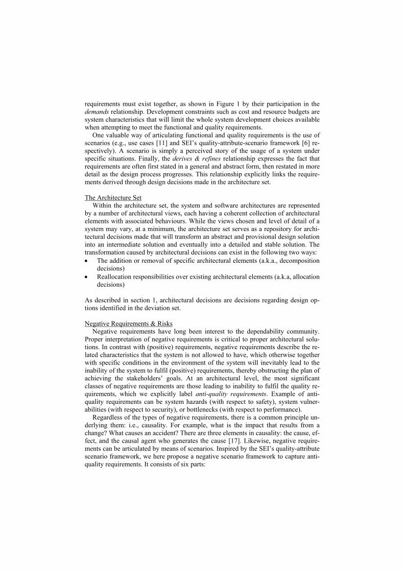
• Source. The entity that generates the stimulus. The source is derived from a spe-cific architectural element under consideration within a chosen view, which can come from the environment of the system or inside the system.
• Stimulus. An undesired condition or event that needs to be considered from the perspective of a specific quality. In our framework, the stimulus is identified by deviation analysis with the aid of proper guidewords.
• Trigger. The conditions under which the stimulus will be generated from the source. The trigger conditions are identified by deductive analysis performed over the chosen view. They may come from the propagation of other negative scenarios identified in the same view or be generated from the related views.
• Environment. The environmental conditions under which the stimulus will inevi-tably lead to the occurrence of the end effect. If these conditions do not exist, then by definition there will be no end effect.
• End effect. An undesired event that results in a specified level of loss or harm. The end effect must be defined with respect to the boundary of the same view from which the stimulus is identified.
• Effect measure. Typically the likelihood of the end effect, the severity, or their combination (i.e. risk). The values can be qualitative or quantitative.
There are several things to note about the expression of the negative scenarios.
Firstly, the definition of a scenario depends upon the architectural context (i.e. the boundaries of existing architectural views and the current level of abstraction), as shown by the inContext relationship in Figure 1. From the perspective of an evolu-tionary system development process, it is necessary to proceed from a coarse view of the negative scenarios to a more refined view that provides a more satisfactory expla-nation, as the design process progresses. A typical example is the system decomposi-tion, in which system-level scenarios are refined into component-level scenarios. Nevertheless, the evaluation of the end effect part is usually performed in a bottom-up manner. Table 1 illustrates anti-safety requirement “inadvertent deployment of thrust reverser” for an aircraft engine control system. This scenario is based upon the archi-tectural context that an aircraft engine contains a thrust reverser as part of the aircraft braking function, which will be activated upon the arrival of specific airframe data. The end effect part of this scenario should be evaluated not only for the engine system level but also for the operational platform (i.e. at the aircraft level).
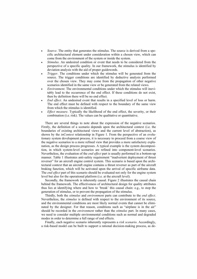
Secondly, the framework is inherently causal. Figure 2 illustrates the causal chain behind the framework. The effectiveness of architectural design for quality attributes thus lies at identifying where and how to ‘break’ this causal chain: e.g., to stop the generation of stimulus, or to prevent the propagation of the stimulus.
Thirdly, both the stimulus and environment parts can contribute to the end effect. Nevertheless, the stimulus is defined with respect to the environment of its source, and the environmental conditions are most likely normal events that cannot be elimi-nated by the designer. For that reason, conditions such as “airplane is in the air” should be recorded in the environment rather than the stimulus part. In many cases, we need to consider multiple environmental conditions such as normal and degraded modes in order to determine a full range of end effects.
Finally, each negative scenario inherently represents a risk scenario. Accordingly, a risk-based model can be built to support a rational decision-making process, as de-
tailed in section 3.2. It is very likely that a scenario may have end effects on multiple attributes, all of which must be evaluated. For instance, a single system upgrade may affect not just modifiability but also performance, usability and safety. We thus need to measure the worst-case end effect (i.e. the most credible and critical one) as the ef-fect measure part.
Table 1. The negative scenario – inadvertent deployment of reverser
Portion of Scenario Possible Value Stimulus Inadvertent deployment of reverser Source Aircraft engine Trigger Invalid airframe data; airframe data transmission loss; engine commission failure Environment Airframe is in air End effect Physical damage to the engine; loss of controlled flight Effect measure Frequency: probable, Severity: catastrophic/critical
Source End EffectStimulus Quality Attributetriggers
environment exists threatens
Fig. 2. The causal chain underlying the negative scenario framework
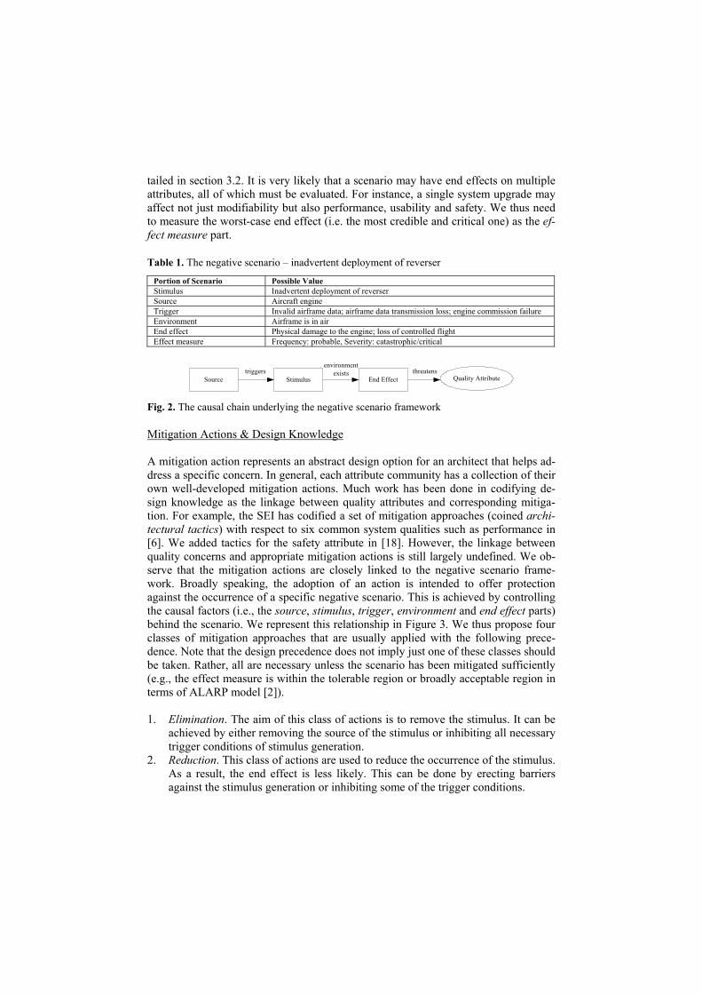
Mitigation Actions & Design Knowledge A mitigation action represents an abstract design option for an architect that helps ad-dress a specific concern. In general, each attribute community has a collection of their own well-developed mitigation actions. Much work has been done in codifying de-sign knowledge as the linkage between quality attributes and corresponding mitiga-tion. For example, the SEI has codified a set of mitigation approaches (coined archi-tectural tactics) with respect to six common system qualities such as performance in [6]. We added tactics for the safety attribute in [18]. However, the linkage between quality concerns and appropriate mitigation actions is still largely undefined. We ob-serve that the mitigation actions are closely linked to the negative scenario frame-work. Broadly speaking, the adoption of an action is intended to offer protection against the occurrence of a specific negative scenario. This is achieved by controlling the causal factors (i.e., the source, stimulus, trigger, environment and end effect parts) behind the scenario. We represent this relationship in Figure 3. We thus propose four classes of mitigation approaches that are usually applied with the following prece-dence. Note that the design precedence does not imply just one of these classes should be taken. Rather, all are necessary unless the scenario has been mitigated sufficiently (e.g., the effect measure is within the tolerable region or broadly acceptable region in terms of ALARP model [2]).
1. Elimination. The aim of this class of actions is to remove the stimulus. It can be
achieved by either removing the source of the stimulus or inhibiting all necessary trigger conditions of stimulus generation.
2. Reduction. This class of actions are used to reduce the occurrence of the stimulus. As a result, the end effect is less likely. This can be done by erecting barriers against the stimulus generation or inhibiting some of the trigger conditions.
3. Resistance. This type of mitigation is intended to stop the propagation of the stimulus into the end effect or switch to a desired system state. In many cases, the effectiveness of resistance actions lies at the detectability of the stimulus.
4. Minimisation. If the occurrence of the end effect is unavoidable, this class of ac-tions provide options to reduce potential loss or harm. It is usually done by pro-viding warning or contingency actions or facilitating emergency procedures.
Source End EffectStimulus
Elimination Reduction Resistance Minimisation
Fig. 3. Four roots of possible mitigation actions
From the above classification, a plausible design approach is to use the negative scenarios as primary to inform possible mitigation action candidates (i.e. architectural design space). In practice, the five parts of the scenario framework are not necessarily controllable. For the example scenario recorded in Table 1, effective mitigation op-tions can be to reduce the occurrence of inadvertent deployment by validating air-frame data and requiring data sample rates, or to detect and resist against the inadver-tent deployment, or to minimise the potential loss by providing auto restow, since removing the engine or eliminating all trigger conditions is impossible. In this case, the source and trigger parts are bound. Parts not bound are considered free. To make an appropriate choice over various mitigation actions, a finer-grained view of mitiga-tion actions is needed. We have codified the knowledge about mitigation actions in terms of the following six portions: • Applicability rules. These rules specify how an action is related to a specific type
of negative scenarios. Examples of factors involved can be, for example, the na-ture of the source (e.g., software, hardware or human), the type of the stimulus (e.g., timing or value failures), the characteristics of the environment (e.g., nor-mal or degraded operational mode), or the value of effect measure (e.g., catastro-phic or major). Hence, the task of specifying the applicability rule part is to ar-ticulate how the action is linked to a specific class of negative scenarios.
• Usage conditions. The usage conditions specify the conditions of the use of a specific action. For example, the use of sanity checking assumes the existence of known pattern of correctness or reasonableness. Some actions are dependent upon the application of other actions. The voting action, for example, requires that some form of redundancy has been employed in the view under considera-tion. In contrast, the use of some actions may imply further application of other actions. A common situation is the use of detection actions that are intended to detect a specific stimulus. Further action such as recovery is usually required upon detection. In short, usage conditions are specified to ensure the integrity of the proper application of an action.
• Design parameters. Many actions have a number of parameters, which determine how the desired mitigation is achieved. For example, in order to use the redun-dancy action, we must determine the number of redundant components, the level of diversity and the redundancy mode (e.g. passive or active redundancy). In
practice, we may defer our decisions regarding the values of design parameters in later in the design process.
• Vulnerabilities. An action itself may bring about new quality concerns (i.e., nega-tive scenarios). For example, the use of voting against value failures will raise a new reliability or safety problem: the robustness of the voting procedure, which can fail due to its underlying hardware or flaw in its algorithm. Codification of the issues can facilitate the next iteration of formulating negative scenarios.
• Side effects. An attribute-specific action often has impact on other attributes in-cluding business attributes such as cost. The side effects can be positive or nega-tive. For the previous example of voting, this action has a significant negative impact on both performance and cost. If we choose to use sanity checking in-stead, then the negative impact on performance and cost is reduced.
• Metrics. The impact of each action should be measurable. The applicable metrics depend upon the type of the actions. For elimination and reduction actions, test-ability and process metrics are often appropriate. For resistance actions, the per-formance and availability metrics are most suitable. For minimisation actions, the usability metrics may be suitable.
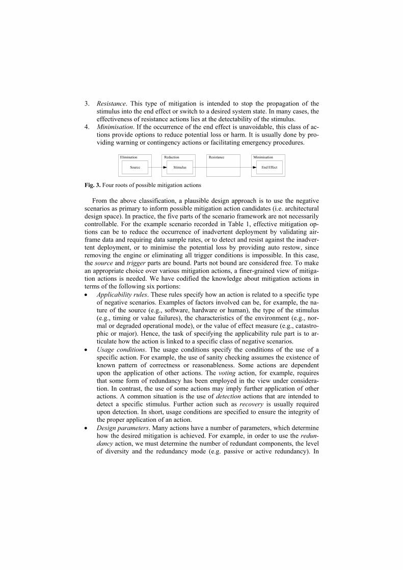
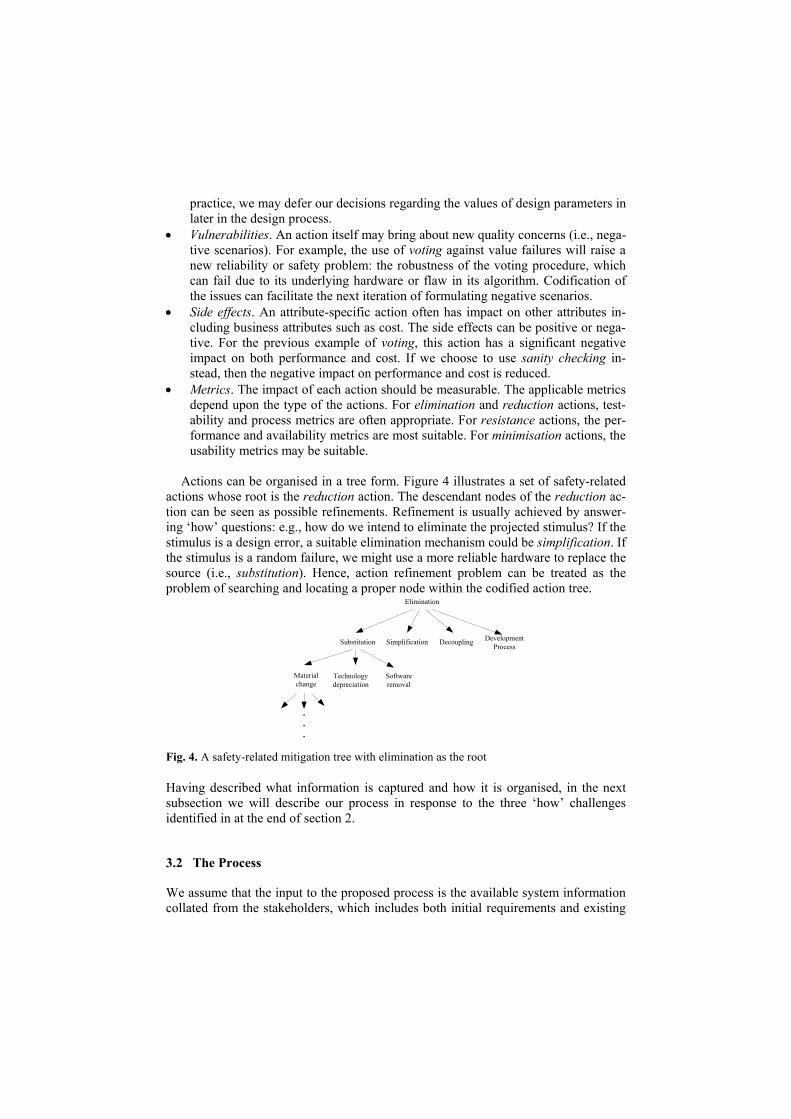
Actions can be organised in a tree form. Figure 4 illustrates a set of safety-related
actions whose root is the reduction action. The descendant nodes of the reduction ac-tion can be seen as possible refinements. Refinement is usually achieved by answer-ing ‘how’ questions: e.g., how do we intend to eliminate the projected stimulus? If the stimulus is a design error, a suitable elimination mechanism could be simplification. If the stimulus is a random failure, we might use a more reliable hardware to replace the source (i.e., substitution). Hence, action refinement problem can be treated as the problem of searching and locating a proper node within the codified action tree.
Elimination
Substitution Simplification Decoupling Development Process
Material change
Technology depreciation
Software removal
.
.
. Fig. 4. A safety-related mitigation tree with elimination as the root
Having described what information is captured and how it is organised, in the next subsection we will describe our process in response to the three ‘how’ challenges identified in at the end of section 2.
3.2 The Process
We assume that the input to the proposed process is the available system information collated from the stakeholders, which includes both initial requirements and existing
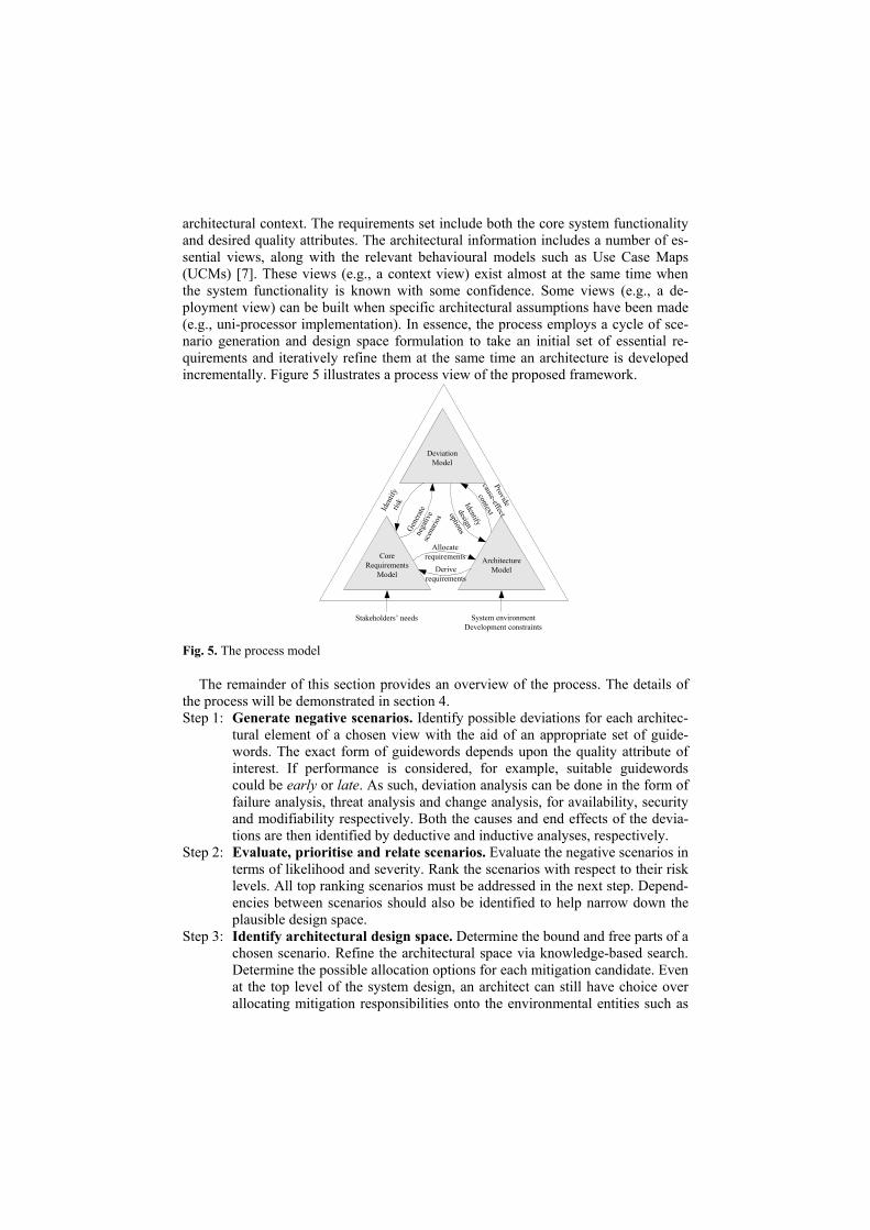
architectural context. The requirements set include both the core system functionality and desired quality attributes. The architectural information includes a number of es-sential views, along with the relevant behavioural models such as Use Case Maps (UCMs) [7]. These views (e.g., a context view) exist almost at the same time when the system functionality is known with some confidence. Some views (e.g., a de-ployment view) can be built when specific architectural assumptions have been made (e.g., uni-processor implementation). In essence, the process employs a cycle of sce-nario generation and design space formulation to take an initial set of essential re-quirements and iteratively refine them at the same time an architecture is developed incrementally. Figure 5 illustrates a process view of the proposed framework.
DeviationModel
CoreRequirements
Model
ArchitectureModel
Iden
tify
risk
Gene
rate
nega
tive
scen
ario
s
Allocate requirements
Derive requirements
Identify
design
options
Provide
cause-effect
context
Stakeholders’ needs System environmentDevelopment constraints
Fig. 5. The process model
The remainder of this section provides an overview of the process. The details of the process will be demonstrated in section 4. Step 1: Generate negative scenarios. Identify possible deviations for each architec-
tural element of a chosen view with the aid of an appropriate set of guide-words. The exact form of guidewords depends upon the quality attribute of interest. If performance is considered, for example, suitable guidewords could be early or late. As such, deviation analysis can be done in the form of failure analysis, threat analysis and change analysis, for availability, security and modifiability respectively. Both the causes and end effects of the devia-tions are then identified by deductive and inductive analyses, respectively.
Step 2: Evaluate, prioritise and relate scenarios. Evaluate the negative scenarios in terms of likelihood and severity. Rank the scenarios with respect to their risk levels. All top ranking scenarios must be addressed in the next step. Depend-encies between scenarios should also be identified to help narrow down the plausible design space.
Step 3: Identify architectural design space. Determine the bound and free parts of a chosen scenario. Refine the architectural space via knowledge-based search. Determine the possible allocation options for each mitigation candidate. Even at the top level of the system design, an architect can still have choice over allocating mitigation responsibilities onto the environmental entities such as
operators or the system under design. The mitigation candidates accompanied by allocation options form the architectural design space, from which the ar-chitect will make principled choices in the next step.
Step 4: Choose architectural options. Determine the benefits, cost, known vulner-abilities and side effects for each option. The benefits are mainly determined by the impact of the selected option upon the level of risk (i.e., the reduction of either the likelihood or severity part). The cost estimate is usually done by the aid of domain experts and past experience. The known vulnerabilities and side effects are identified in the codified design knowledge. Note that our method does not make decisions for the architects but simply aids them in elicitating and rationalising their decisions. The architect is free to choose specific option(s) for the purpose of balancing the potential costs against the benefits and residual risks.
Step 5: Derive and formulate quality requirements. Determine the exact portions of the negative scenario that a selected option is intended to address. Deter-mine the corresponding action metrics with the aid of the codified design knowledge. Based upon the types of metrics, develop the corresponding qual-ity requirements by means of the (positive) quality attribute scenarios.
Step 6: Formulate architectural views. Refine the existing architectural views and build new views if applicable, given the architectural decisions made and the set of quality requirements formulated.
Repeat the steps above. The process stops when all identified negative scenarios have been addressed sufficiently.
4 Case Study
The example concerns the design of a system consisting of a number of Automated Guided Vehicles (AGVs) that deliver pallets from an automated warehouse to ma-chine tools as requested by an operator through a Central Control Computer (CCC). The most important system function here is pallet delivery. Five desired quality at-tributes are initially elicited from the stakeholders: safety, reliability, availability, modifiability, and performance. Among these attributes, the safety goal is the most important and mandates that the level of risk within the plant should be improved by the introduction of AGVs, as there have been three major injuries from the manually operated fork-lifts in the past 15 years. Alongside this safety goal, two safety con-straints are identified for the operational platform: • AGV must not enter the prohibited area. • Correct pallets for the selected programme of machine tools must be used.
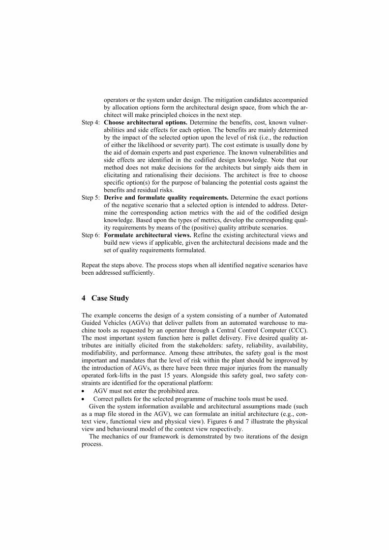
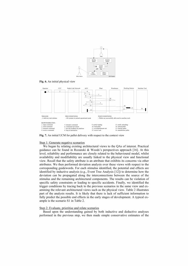
Given the system information available and architectural assumptions made (such as a map file stored in the AGV), we can formulate an initial architecture (e.g., con-text view, functional view and physical view). Figures 6 and 7 illustrate the physical view and behavioural model of the context view respectively.
The mechanics of our framework is demonstrated by two iterations of the design process.
Sensing System
ActuationSystem
Control System
Other Functions
Battery System
Plant
Other Actors AGV System Fig. 6. An initial physical view
Operator CCC AGV Plant Warehouse Docking Station Machine Tool
1 2 3 45 6 78
9
13
6 78
11 15
RESPONSIBILITIES:1. input command2. send command3. transmit command4. receive command
TRIGGER:- A delivery task initiates
PRECONDITIONS:- All systems in normal operational mode
POSTCONDITIONS:- Pallets are successfully delivered to machine tools
Radio Link Network
16
10
14
12 11
12
5. interpret command6. command movement7. provide feedback & platform8. stop at destination
9. notify loading10. load pallet11, accomplishment ack12. receive ack
13. notify unloading14. unload pallet15. transfer pallet16. manufacture pallet
Fig. 7. An initial UCM for pallet delivery with respect to the context view
Step 1: Generate negative scenarios We began by relating existing architectural views to the QAs of interest. Practical
guidance can be found in Rozanski & Woods’s perspectives approach [16]. At this level, reliability and performance are closely related to the behavioural model, whilst availability and modifiability are usually linked to the physical view and functional view. Recall that the safety attribute is an attribute that exhibits its concerns via other attributes. We then performed deviation analysis over these views with respect to the corresponding guidewords. For each stimulus identified, the potential end effects are identified by inductive analysis (e.g., Event Tree Analysis [12]) to determine how the deviation can be propagated along the interconnections between the source of the stimulus and the remaining architectural components. The results can be violation of specific safety constraints or leading to specific accidents. Finally, we identified the trigger conditions by tracing back to the previous scenarios in the same view and ex-amining the relevant architectural views such as the physical view. Table 2 illustrates part of the analysis results. It is likely that there is lack of sufficient information to fully predict the possible end effects in the early stages of development. A typical ex-ample is the scenario S1 in Table 2.
Step 2: Evaluate, prioritise and relate scenarios
Based upon the understanding gained by both inductive and deductive analyses performed in the previous step, we then made simple conservative estimates of the

likelihood and severity of each scenario. Sometimes, the likelihood estimate may be derived from historical data or through expert judgement. Arguably, in the early de-velopment process, it is only possible to make order of magnitude estimates of the likelihood and severity in a qualitative manner. Where there was uncertainty associ-ated with scenarios such as S1, we simply skipped the corresponding estimation. We then determined their risk levels by means of risk classification [2]. The scenarios un-der evaluation were prioritised with respect to the level of risk calculated. Finally, we identified the dependencies between scenarios. Part of evaluation results are shown in Table 3. The most significant scenarios identified in this example are S22, S6 and S24. These must be addressed in the next step. For uncertain scenarios such as S1, they are still valid for design considerations in the next step, as they contribute to the most critical scenario S6.
Table 2. A subset of deviation analysis results
ID QA View Source Stimulus Trigger End Effect S1 Opera-
tor Incorrect user input
Human error Erroneous command may be propagated through the use case path (N/A)
S6 AGV Not go to the destina-tion as re-quested
S1; AGV sensing failure; AGV c/s failure (s/w design error or processor fault); S22
Manufacturing is interrupted (anti-availability); AGV enters prohib-ited area (anti-safety)
S8
Reli-ability
Ware-house
Load incor-rect pallets
Warehouse control computer failure
Wrong loads delivered to machine tool (anti-safety)
S16 Performance
UCM for pal-let de-livery
AGV Late arrival Inefficient naviga-tion
Manufacturing is delayed (anti-performance)
S18 Avail-ability
Physical view
AGV Battery fail-ure
Battery flat; wir-ing fault
Manufacturing is interrupted (anti-availability)
S22 Func-tional view
Plant Layout change
Plant maintenance or business expan-sion
Rework of AGV software (anti-modifiability); AGV does not go to the destination as requested (S6)
S23
Modi-fiabil-ity
Physical view
AGV Sensor up-grade
AGV maintenance Rework of AGV software (anti-modifiability); Introduction of new fault (N/A)
S24 Safety Context view
Plant Obstacle present
Workers or other AGVs
Collision (anti-safety)
Step 3: Identify design space
In this step, we first determined the bound and free parts for each scenario. For the example scenario S6 in Table 3, the source part is bound, whilst the stimulus and en-vironment parts are clearly free. The end effect part is also assumed to be bound, as there is almost nothing that can be done once AGV enters the prohibited area. We then identified the mitigation actions with respect to application rules and usage con-ditions. For S6, a suitable reduction action is simplicity that inhibits part of the trigger conditions (i.e., design errors of the AGV software system). For each candidate ac-tion, we also identified the associated possible allocation options. For the example of S8, an effective mitigation action candidate is detection, which in turns leads to two allocation options: whether to place onus on the AGV or machine tools to sense when the wrong parts are being delivered. Finally, we created the architectural design space by relating the candidate actions to allocation options. Table 4 shows a subset of the architectural design space for the scenario S6, accompanied by their purpose.
Step 4: Choose architectural options The benefit of each option was determined in terms of its impact upon the fre-
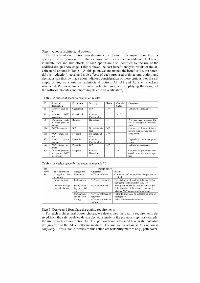
quency or severity measures of the scenario that it is intended to address. The known vulnerabilities and side effects of each option are also identified by the use of the codified design knowledge. Table 5 shows the cost-benefit analysis results of the ar-chitectural options in Table 4. At this point, we understood the benefits (i.e. the poten-tial risk reduction), costs and side effects of each proposed architectural option, and decisions can thus be made upon judicious consideration of these options. For the ex-ample of S6, we chose the architectural options A1, A2 and A3 (i.e., checking whether AGV has attempted to enter prohibited area, and simplifying the design of the software modules and improving its ease of verification).
Table 3. A subset of scenario evaluation results
ID Scenario description
Frequency Severity Rank Contri- butor
Comments
S1 Incorrect user in-put
Occasional N/A N/A Unknown consequence
S6 Incorrect AGV navigation
Occasional Critical/ Catastrophic
2 S1, S22
S8 Warehouse loads incorrect parts of pallets
Remote Hazardous 6 We may need to assess the cost of damages of machine tools
S16 AGV late arrival N/A No safety ef-fect
N/A
S18 AGV battery fail-ure
Frequent No safety ef-fect
N/A
Commercial losses of inter-rupting manufacture are not considered
S22 Plant layout changes
Probable Critical/ Catastrophic
1 Depends on the actual plant layout
S23 AGV sensor up-grade
Probable N/A N/A Unknown consequence
S24 Obstacle presents in path of AGV movement
Frequent Critical/ Hazardous
2 S6 Collision in prohibited area could cause far worse inju-ries
Table 4. A design space for the negative scenario S6
Design Space Sce-nario Part addressed Mitigation Allocation Intent
Navigation de-sign error
Simplicity AGV c/s software Correctness of the software design can be verified
Processor fault Redundancy AGV c/s processor The likelihood of random failures of redun-dant components is sufficiently low
Sanity check-ing and fail stop
AGV c/s software AGV position can be used to indicate pos-sible violation of the safety constraint (i.e., whether AGV enters prohibited area)
Comparison and fail stop
AGV c/s software or hardware
Value failures can be detected in case of discrepancy
S6
Incorrect naviga-tion calculation
Voting AGV c/s software or hardware
Value failures can be tolerated
Step 5: Derive and formulate the quality requirements
For each architectural option chosen, we determined the quality requirements de-rived from the safety-related design decisions made in the previous step. For example, the use of architectural option A1. The portion being addressed here is the potential design error of the AGV software modules. The mitigation action in this option is simplicity. Thus suitable metrics of this action are testability metrics (e.g., path cover-
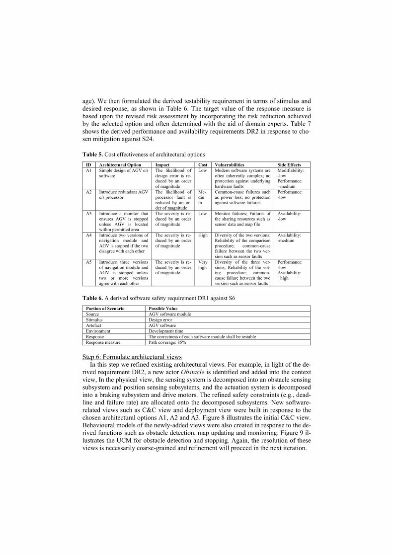
age). We then formulated the derived testability requirement in terms of stimulus and desired response, as shown in Table 6. The target value of the response measure is based upon the revised risk assessment by incorporating the risk reduction achieved by the selected option and often determined with the aid of domain experts. Table 7 shows the derived performance and availability requirements DR2 in response to cho-sen mitigation against S24.
Table 5. Cost effectiveness of architectural options
ID Architectural Option Impact Cost Vulnerabilities Side Effects A1 Simple design of AGV c/s
software The likelihood of design error is re-duced by an order of magnitude
Low Modern software systems are often inherently complex; no protection against underlying hardware faults
Modifiability: -low Performance: +medium
A2 Introduce redundant AGV c/s processor
The likelihood of processor fault is reduced by an or-der of magnitude
Me-dium
Common-cause failures such as power loss; no protection against software failures
Performance: -low
A3 Introduce a monitor that ensures AGV is stopped unless AGV is located within permitted area
The severity is re-duced by an order of magnitude
Low Monitor failures; Failures of the sharing resources such as sensor data and map file
Availability: -low
A4 Introduce two versions of navigation module and AGV is stopped if the two disagree with each other
The severity is re-duced by an order of magnitude
High Diversity of the two versions; Reliability of the comparison procedure; common-cause failure between the two ver-sion such as sensor faults
Availability: -medium
A5 Introduce three versions of navigation module and AGV is stopped unless two or more versions agree with each other
The severity is re-duced by an order of magnitude
Very high
Diversity of the three ver-sions; Reliability of the vot-ing procedure; common-cause failure between the two version such as sensor faults
Performance: -low Availability: +high
Table 6. A derived software safety requirement DR1 against S6
Portion of Scenario Possible Value Source AGV software module Stimulus Design error Artefact AGV software Environment Development time Response The correctness of each software module shall be testable Response measure Path coverage: 85%
Step 6: Formulate architectural views
In this step we refined existing architectural views. For example, in light of the de-rived requirement DR2, a new actor Obstacle is identified and added into the context view, In the physical view, the sensing system is decomposed into an obstacle sensing subsystem and position sensing subsystems, and the actuation system is decomposed into a braking subsystem and drive motors. The refined safety constraints (e.g., dead-line and failure rate) are allocated onto the decomposed subsystems. New software-related views such as C&C view and deployment view were built in response to the chosen architectural options A1, A2 and A3. Figure 8 illustrates the initial C&C view. Behavioural models of the newly-added views were also created in response to the de-rived functions such as obstacle detection, map updating and monitoring. Figure 9 il-lustrates the UCM for obstacle detection and stopping. Again, the resolution of these views is necessarily coarse-grained and refinement will proceed in the next iteration.

Table 7. A derived performance and availability requirement DR2 against S24
Portion of Scenario Possible Value Source Plant Stimulus Obstacle present Artefact AGV Environment AGV is moving towards the obstacle Response AGV shall detect the obstacle and stop the vehicle in time Response measure Deadline: 0.1second, failure rate: 2.5E-5 /hour
Navigation
Monitor
Sensor
Motor
Enable
Movement
Fig. 8. A fragment of the C&C view (without consideration of other functionality)
Control SystemObstacle Obstacle Sensing System Drive Motor Braking System
1 2 3
4
6
5
TRIGGER:- A delivery task initiates
PRECONDITIONS:- All systems in normal operational mode
RESPONSIBILITIES:1. signal detection2. receive signal3. command motor OFF4. command brakes ON5. power off6. apply brakes
Fig. 9. UCM for obstacle detection and stopping
Second Iteration In the second iteration, rather than repeat full-scale deviation analysis, we may
choose to seek possible deviations over existing views that contribute to the failures of the chosen mitigation mechanisms in the first iterations: i.e., obstacle detection & stopping, map updating, and navigation monitoring. For the example of UCM in Fig-ure 9, failures of either the obstacle sensing subsystem or control system are possible deviations that can lead to total loss of the stopping function. Further deductive analy-sis performed over the physical view revealed that battery failure (S18) is a possible cause of the control system failure. In this case, the scenario S18 that had been dem-onstrated to be ‘safe’ in the first iteration now has a new safety effect on the collision if it occurs when the AGV is approaching an obstacle. It is therefore necessary to trace back to the previous scenarios and revise them if new effects are discovered. Moreover, architectural assumptions (e.g., obstacle is detectable) made in the previ-ous iteration need to be confirmed in this iteration. For instance, further studies reveal that the obstacles in the prohibited area such as AGV falling over edges may not be detectable. As such, we re-evaluated all elicited or revised scenarios and identified the most significant scenarios at this level, from which the decision-making procedure could be facilitated. For example, a decision was made to use dual redundancy to pro-tect against the single point of failure of obstacle sensing. As a result, the obstacle sensing system is decomposed into a proximity sensing and bumper subsystem.
The number of iterations needed and scenarios generated range in terms of the size of the system and the risk acceptability criteria. For the medium-size systems such as the above AGV example, our experience shows that 4-6 iterations and 30-50 scenar-ios are quite likely. We would anticipate the number of scenarios to be larger for in-dustrial-scale studies.
5 Discussion
In this section, we will discuss the major findings based on the preliminary results of our experiments. Related work is also discussed here for the purpose of comparison. • Application domain. The proposed framework was developed for the safety-
critical system domain. However, the generic nature of the framework (i.e. the negative scenarios and mitigation action model) makes it potentially applicable in other domains, such as security-critical systems and performance-critical sys-tems, in which non-safety effects such as commercial loss and mission loss are also taken into account.
• Role of negative requirements. We feel that existing practice advocates stake-holder-centric requirements elicitation and there is little guidance on capturing negative requirements. Although quality requirements are initially elicited from the stakeholders, they are often by no means complete and precise. We argue that the notion of negative requirements offers an argumentative approach to inter-preting and addressing quality requirements in a recursive manner. The essence of this perspective is an open-ended process of defining and debating the issues occurring in the achievement of quality requirements, thereby helping discover and enhancing existing quality requirements. Our approach is closely related to the misuse cases approach [4] in which negative requirements are identified by deviation analysis over existing use cases and captured in a form similar to use cases. New use cases are then derived in response to the mitigation against the identified misuse cases. However, this approach is defined solely in the func-tional context without consideration of architectural characteristics.
• Design rationale. Our framework is inherently consistent with existing argument-based design rationale techniques such as REMAP [15]. Our negative require-ments are similar to their “issues” and mitigation actions are equivalent to their “positions”. Negative requirements (i.e. issues) are identified by deviation analy-sis, which is strongly influenced by our recent work on failure modelling [19], and the design space is identified and controlled by means of causality and risk assessment. One missing step in our proposed framework is the linkage between risk model and quality-attribute model such as performance and reliability mod-els, which determines how quality requirements can be derived with respect to mitigation actions chosen. The SEI has recently proposed a quality-attribute rea-soning framework [5] that unifies various quality attribute models. We anticipate that incorporation of this reasoning framework into our scheme will be possible.
• Risk assessment. Within the proposed framework, the risk assessment is demon-strably qualitative. However, it is envisioned that a quantitative approach may also be possible and would complement its qualitative counterpart. NASA pro-vides a lightweight solution to quantitative risk assessment [10], which may be incorporated into our framework.
• Cost-benefit analysis. We adopt the likelihood-severity matrix as the basis of lightweight cost-benefit analysis, in which the ALARP model has been incorpo-rated. Our findings reveal that the use of the matrix simplifies the analysis and saves repeated analysis work in subsequent design refinements. A comparable approach is the SEI’s CBAM [6] in which benefits and cost are determined by the
agreement of the stakeholders. We argue that CBAM is a laborious effort-intensive process and thus may be hard to apply many times over as part of an evolutionary development process, though its analysis results tend to be more ac-curate and complete.
6 Conclusions
We have presented a concrete framework for eliciting and rationalising architectural design decisions for safety-critical software systems. In particular, we have demon-strated how it is practical to elicit and formulate negative requirements using a sce-nario framework to inform architectural design decisions and justify the rationale be-hind them. Based upon the results of adaptations of the co-evolution of requirements and architectures to the safety domain, we justify the rationale for deriving safety re-quirements that can then form part of the architectural design. Through provision of such a framework, we believe that there can be increased confidence in the selection of mitigation mechanisms.
References
1. ARP 4761: Guidelines and Methods for Conducting the Safety Assessment Process on Civil Airborne Systems and Equipment. Society of Automotive Engineers, Inc (1996)
2. IEC 61508 – Functional Safety of Electrical/Electronic/Programmable Electronic Safety-Related Sys-tems. International Electrotechnical Commission (1998).
3. The United Modelling Language Specification 1.5. Object Management Group, http://www.uml.org 4. Alexander, I.: Misuse Cases: Use Cases with Hostile Intent. IEEE Software, 20 (1) (2003) 58-66 5. Bachmann, F., Bass, L. and Klein, M.: Deriving Architectural Tactics: A Step toward Methodical Archi-
tectural Design. Tech. Report. CMU/SEI-2003-TR-004. SEI (2003) 6. Bass, L., Clements, P. and Kazman, R.: Software Architecture in Practice. 2nd Edition. Addison Wesley,
Reading, USA (2003) 7. Buhr, R.J.A. and Casselman, R.S.: Use Case Maps for Object-Oriented Systems. Prentice Hall (1996) 8. Burns, A. and Lister, A.: A Framework for Building Dependable Systems. The Computer Journal, 34 (2).
(1991) 173-181 9. Douglass, B.P.: Doing Hard Time: Developing Real-Time Systems with UML, Objects, Frameworks,
and Patterns. Addison-Wesley (1999) 10. Feather, M.S., and Cornford, S.L.: Quantitative Risk-Based Requirements Reasoning. Requirements
Engineering, 8 (4) (2003) 248-265 11. Kruchten, P.: The 4+1 View Model of Architecture. IEEE Software, 12 (6) (1995) 42-50 12. Leveson, N.G.: Safeware: System Safety and Computers. Addison-Wesley (1995) 13. Lions, J.L.: ARIANE 5: Flight 501 Failure. Inquiry Board report. Paris (1996) 14. Nuseibeh, B.: Weaving Together Requirements and Architectures. IEEE Computer, 34 (3) (2001) 115-
114 15. Ramesh, B. and Dhar, V.: Supporting systems development by capturing deliberations during require-
ments engineering. IEEE Trans. on Software Engineering, 18 (6) (1992) 498-510 16. Rozanski, N. and Woods, Eoin: Software Systems Architecture. Addison-Wesley (2005) 17. Sosa, E. and Tooley, M. (eds.): Causation. Oxford University Press, New York (1993) 18. Wu, W. and Kelly, T.: Safety Tactics for Software Architecture Design. Proceedings of the 28th Annual
International Computer Software and Applications Conference (COMPSAC’04). IEEE Computer Soci-ety (2004) 368-375
19. Wu, W. and Kelly, T.: Failure Modelling in Software Architecture Design for Safety. ACM SIGSOFT Software Engineering Notes, 30 (4) (2005) 1-7