architectural patterns revisited – a pattern...
TRANSCRIPT
Architectural Patterns Revisited – A PatternLanguage
Paris Avgeriou Uwe ZdunCONCERT division Department of Information Systems
Fraunhofer IPSI Vienna University of Economics and BADarmstadt, Germany Vienna, Austria
[email protected] [email protected]
Architectural patterns are a key concept in the field of software architecture: they offerwell-established solutions to architectural problems, help to document the architecturaldesign decisions, facilitate communication between stakeholders through a common vo-cabulary, and describe the quality attributes of a software system as forces. Regrettably,finding and applying the appropriate architectural patterns in practice still remains largelyad-hoc and unsystematic. This is due to the lack of consensus in the community withrespect to the “philosophy” and granularity of architectural patterns, as well as the lackof a coherent pattern language. In this paper we attempt to establish common ground inthe architectural patterns community by proposing a pattern language that acts as a super-set of the existing architectural pattern collections and categorizations. This language isparticularly focused on establishing the relationships between the patterns and performs acategorization based on the concept of “architectural views”.
1 Motivation
The software architecture community has had many debates on various aspects like which de-sign and evaluation methods, Architecture Description Languages, and views are best for whichcase. Architectural patterns were one of the few points, where consensus was achieved in thefield of software architecture: their significance is well-established and they are essential toan architecture description [SC97, SG96, BCK98, CBB+02, BMR+96, SSRB00]. Regrettably,describing, finding, and applying architectural patterns in practice still remains largely ad-hocand unsystematic. This is due to several issues that are still not resolved: there is a semanticgap concerning what architectural patterns really represent, what is the philosophy behind them;moreover, there is much confusion with respect to what is the granularity of architectural pat-terns; finally there is no accepted classification or cataloguing of patterns that can be used byarchitects. The next paragraphs elaborate on these issues.
There are two different “schools of thought” in the literature with respect to the nature of ar-chitectural patterns: one that uses the term “architectural pattern” (e.g. in [BMR+96, SSRB00,VKZ04]) and another that uses the term “architectural style” (e.g. in [SG96, SC97, BCK98,CBB+02]). Both terms refer to recurring solutions that solve problems at the architectural de-sign level, and provide a common vocabulary in order to facilitate communication. They both
D3 – 1
also accept that patterns provide the means to reason for the quality attributes of a software sys-tem and help to document the design decisions taken by the architect. But they have some keydifferences in their underlying philosophy:
• In the architectural patterns perspective, patterns are considered as problem-solution pairsthat occur in a given context and are affected by it. Furthermore a pattern does not onlydocument “how” a solution solves a problem but also “why” it is solved, i.e. the rationalebehind this particular solution. In particular, the description of the problem pays muchattention to the forces that shape the problem, while the solution elaborates on how (andif) those forces are resolved. The description of architectural patterns is based on thecontext-problem-solution triplet and may be further elaborated with richer details, espe-cially focusing on the rationale behind a solution. Moreover, patterns are meant to worksynergistically in the context of a pattern language, and have numerous inter-dependenciesamong each other. Finally, there are a number of postulations for a solution to qualify asa pattern. For instance, the pattern must capture common practice (e.g. have at least threeknown uses) and at the same time the solution of the pattern must be non-obvious. Pat-terns should provide aesthetic solutions, and in the pattern literature the human aspect ofsoftware is accentuated [Cop96].
• In the architectural styles perspective, the problem does not receive much attention nordoes the rationale behind choosing a specific solution. In [SC97, BCK98] a style is lookedupon in terms of components, connectors, and issues related to control and data flow. In[SG96] attention is drawn to architectural configurations, semantics of the styles, and po-tential architectural analysis that can be performed on the systems built on the styles. In[BCK98, CBB+02] the concept of architectural styles is treated as a set of constraintson components, connectors, and their interactions. Similarly, in [MM03], an architecturalstyle is represented by components, connectors, their configurations, and constraints uponall of them. In this viewpoint, patterns are not considered generic and “timeless” in theAlexandrian sense [AIS+77, Ale79], but become much more concrete and focused. Thisalso leads to multiple variations of the same pattern in order to solve specialized designproblems [SC97]. Also, since the pattern’s implementation details can be pinpointed, Ar-chitecture Description Languages [MT00] can be designed in order to support individualarchitectural patterns.
As far as the granularity of architectural patterns is concerned, it is usually not clear when apattern is “big” enough to be considered architectural. In particular, the category of “designpatterns”, e.g. as described in [GHJV94], are often referred to, or used as architectural patterns.In general it is hard to draw the line between architectural patterns and design patterns. In fact,it depends heavily on the viewpoint of the designer or architect whether a specific pattern iscategorized as an architectural pattern or a design pattern. Consider for instance, a classicaldesign pattern, theINTERPRETERpattern [GHJV94]. The description in [GHJV94] presents itas a concrete design guideline. Yet, instances of the pattern are often seen as a central elementsin the architecture of software systems, because anINTERPRETERis a central, externally visiblecomponent – i.e. the pattern is treated like an architectural pattern (see [SG96]).
Finally, there is no single catalogue of architectural patterns for software architects to use. In-stead there is a voluminous and heterogeneous literature of patterns, where the various patterns
D3 – 2
differ in their philosophy and way of description and are often not related in the context ofa pattern language. To make matters worse, many architectural patterns languages have beendeveloped since the earlier software patterns literature [SG96, SC97, BMR+96, GHJV94] hasbeen documented, but the former are not clearly related to the latter. Of course, there have beenattempts to classify architectural patterns: in [BMR+96] architectural patterns are categorizedaccording to the global system properties that they support; in [SC97, BCK98] architecturalpatterns are classified with respect to a framework of features, like the types of components andconnectors, and control and data issues; a more recent classification scheme that has been pro-posed is based on the concept of architectural views [CBB+02]. But again there is no consensuson these classifications that could possibly lead to a single scheme.
2 Putting the pieces together: a pattern language
2.1 The approach
In this paper we attempt to findcommon groundin the architectural patterns community byproposing a pattern language that acts as a superset of the existing architectural pattern collec-tions and categorizations. This language, as a whole, is greater than the sum of its parts becauseit particularly focuses on establishing the relationships between the patterns in order to presentthe “big picture”. In particular this pattern language tackles the aforementioned shortcomingsin the following ways:
• We consider that both architectural patterns and architectural styles are in essence thesame concepts and that they only differ in using different description forms. Therefore, weput both the “classical” architectural patterns such as those from POSA (see [BMR+96])and the architectural styles from SEI (see [SC97, Sha96, SG96, BCK98, CBB+02]) inthe same pattern language, paying special attention on relating them with each other. Forthe sake of simplicity, we shall use only the term “architectural pattern” for the rest ofthis paper. Note that we are aware that some patterns described below, e.g.EXPLICIT
INVOCATION would not qualify as patterns in a strict interpretation of the pattern defini-tion, because they may be considered as stating really obvious solutions. Naturally, theobviousness of a solution is a matter of definition. We nevertheless include them in ourpattern language because they are important pieces of the architectural patterns puzzle andsubstantially contribute in putting the individual architectural styles and patterns togetherinto a coherent pattern language.
• We consider a pattern to be architectural, if it refers to a problem at the architectural levelof abstraction; that is, if the pattern covers the overall system structure and not only afew individual subsystems. Thus we have not included the classical “design patterns”(e.g. [GHJV94]) in our pattern language except for one (INTERPRETER). However weemphasize that these design patterns can potentially be used as architectural patterns, ifone applies them at the level and scope of a system’s architecture.
• We propose a classification of the architectural patterns, based upon architectural views,that extends the one proposed in [CBB+02]. The next subsection elaborates on this clas-sification scheme.
D3 – 3
This pattern language, as aforementioned, contains patterns from existing collections of archi-tectural patterns. The emphasis of this language is therefore not on describing the individualpatterns; they have already been elaborately described before. For space restrictions we don’trepeat these descriptions here. Instead emphasis is given only on the related pattern sectionsthat analytically describe the relationships between the patterns. Consequently, the intended au-dience for this pattern language is comprised of architects that have a sound knowledge of thesepatterns and can accordingly understand the “big picture” of the inter-related patterns.
2.2 Classification of architectural patterns according to views
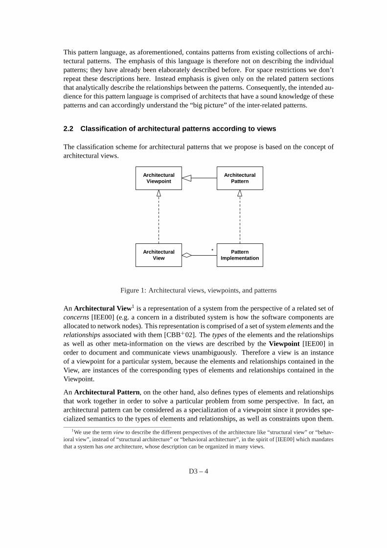
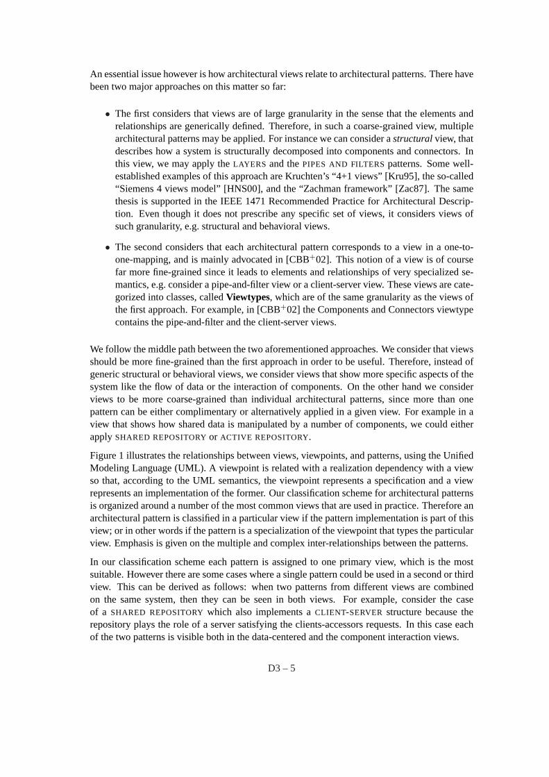
The classification scheme for architectural patterns that we propose is based on the concept ofarchitectural views.
ArchitecturalViewpoint
ArchitecturalView
ArchitecturalPattern
* * PatternImplementation
Figure 1: Architectural views, viewpoints, and patterns
An Architectural View 1 is a representation of a system from the perspective of a related set ofconcerns[IEE00] (e.g. a concern in a distributed system is how the software components areallocated to network nodes). This representation is comprised of a set of systemelementsand therelationshipsassociated with them [CBB+02]. Thetypesof the elements and the relationshipsas well as other meta-information on the views are described by theViewpoint [IEE00] inorder to document and communicate views unambiguously. Therefore a view is an instanceof a viewpoint for a particular system, because the elements and relationships contained in theView, are instances of the corresponding types of elements and relationships contained in theViewpoint.
An Architectural Pattern , on the other hand, also defines types of elements and relationshipsthat work together in order to solve a particular problem from some perspective. In fact, anarchitectural pattern can be considered as a specialization of a viewpoint since it provides spe-cialized semantics to the types of elements and relationships, as well as constraints upon them.
1We use the termview to describe the different perspectives of the architecture like “structural view” or “behav-ioral view”, instead of “structural architecture” or “behavioral architecture”, in the spirit of [IEE00] which mandatesthat a system hasonearchitecture, whose description can be organized in many views.
D3 – 4
An essential issue however is how architectural views relate to architectural patterns. There havebeen two major approaches on this matter so far:
• The first considers that views are of large granularity in the sense that the elements andrelationships are generically defined. Therefore, in such a coarse-grained view, multiplearchitectural patterns may be applied. For instance we can consider astructuralview, thatdescribes how a system is structurally decomposed into components and connectors. Inthis view, we may apply theLAYERS and thePIPES AND FILTERSpatterns. Some well-established examples of this approach are Kruchten’s “4+1 views” [Kru95], the so-called“Siemens 4 views model” [HNS00], and the “Zachman framework” [Zac87]. The samethesis is supported in the IEEE 1471 Recommended Practice for Architectural Descrip-tion. Even though it does not prescribe any specific set of views, it considers views ofsuch granularity, e.g. structural and behavioral views.
• The second considers that each architectural pattern corresponds to a view in a one-to-one-mapping, and is mainly advocated in [CBB+02]. This notion of a view is of coursefar more fine-grained since it leads to elements and relationships of very specialized se-mantics, e.g. consider a pipe-and-filter view or a client-server view. These views are cate-gorized into classes, calledViewtypes, which are of the same granularity as the views ofthe first approach. For example, in [CBB+02] the Components and Connectors viewtypecontains the pipe-and-filter and the client-server views.
We follow the middle path between the two aforementioned approaches. We consider that viewsshould be more fine-grained than the first approach in order to be useful. Therefore, instead ofgeneric structural or behavioral views, we consider views that show more specific aspects of thesystem like the flow of data or the interaction of components. On the other hand we considerviews to be more coarse-grained than individual architectural patterns, since more than onepattern can be either complimentary or alternatively applied in a given view. For example in aview that shows how shared data is manipulated by a number of components, we could eitherapplySHARED REPOSITORYor ACTIVE REPOSITORY.
Figure 1 illustrates the relationships between views, viewpoints, and patterns, using the UnifiedModeling Language (UML). A viewpoint is related with a realization dependency with a viewso that, according to the UML semantics, the viewpoint represents a specification and a viewrepresents an implementation of the former. Our classification scheme for architectural patternsis organized around a number of the most common views that are used in practice. Therefore anarchitectural pattern is classified in a particular view if the pattern implementation is part of thisview; or in other words if the pattern is a specialization of the viewpoint that types the particularview. Emphasis is given on the multiple and complex inter-relationships between the patterns.
In our classification scheme each pattern is assigned to one primary view, which is the mostsuitable. However there are some cases where a single pattern could be used in a second or thirdview. This can be derived as follows: when two patterns from different views are combinedon the same system, then they can be seen in both views. For example, consider the caseof a SHARED REPOSITORYwhich also implements aCLIENT-SERVER structure because therepository plays the role of a server satisfying the clients-accessors requests. In this case eachof the two patterns is visible both in the data-centered and the component interaction views.
D3 – 5
The views that we have chosen for this classification scheme contain mainly two types of el-ements:componentswhich are units of runtime computation or data-storage, andconnectorswhich are the interaction mechanisms between components [PW92, CBB+02]. There are ofcourse other views that contain different kinds of elements, which we did not include in ourpattern language for the time being. For instance in [CBB+02] the “module” views deal withimplementation modules (e.g. Java or C++ classes), while the “allocation” views deal withhow software elements are allocated to environment elements (e.g. code units are allocated tomembers of the development team).
2.3 Overview of the pattern language
The following pattern language is comprised of component and connector views, and the pat-terns that are classified in each view. Note that we focus on “classical” architectural patternsfrom both POSA (see [BMR+96]) and SEI (see [SC97, Sha96, SG96, BCK98, CBB+02]), be-cause these have been well-established in the software architecture community. We have alsoincluded a few patterns from other sources, in order to describe important links or gaps in therealm of the “classical” architectural patterns. We also discuss some links to related patternlanguages inside the description of the patterns.
• The Layered View deals with how the system as a complex heterogeneous entity can bedecomposed into interacting parts.
– LAYERS [SC97, Sha96, SG96, BCK98, CBB+02, BMR+96]
– INDIRECTION LAYER [Zdu04, Zdu03] (a variant of this pattern is called “virtualmachine” in [CBB+02])
• The Data Flow View deals with how streams of data are successively processed or trans-formed by components.
– BATCH SEQUENTIAL [SG96, SC97, BCK98]
– PIPES AND FILTERS[SC97, Sha96, SG96, BCK98, CBB+02, BMR+96]
• The Data-centered View is appropriate when the concerns involve how a central repositoryof data is accessed by multiple components.
– SHARED REPOSITORY[VKZ04] (called “repository” in [SG96, Sha96, BCK98])
– ACTIVE REPOSITORY(called “blackboard” in [SC97, BCK98])
– BLACKBOARD [BMR+96, SG96]
• The Adaptation View deals with how the system adapts itself during evolution.
– MICROKERNEL [BMR+96]
– REFLECTION [BMR+96]
– INTERCEPTOR[SSRB00]
• The Language Extension View is concerned with how systems offer an abstraction layerto the computation infrastructure.
D3 – 6
– INTERPRETER[SG96, Sha96, BCK98, GHJV94]
– VIRTUAL MACHINE [GMSM00]
– RULE-BASED SYSTEM[SG96, BCK98]
• The User Interaction View shows the runtime structure of components that offer a userinterface.
– MODEL-VIEW-CONTROLLER [KP88, BMR+96]
– PRESENTATION-ABSTRACTION-CONTROL [Cou87, BMR+96]
– C2 [TMA +96]
• The Component Interaction View focuses on how individual components exchange mes-sages but retain their autonomy.
– EXPLICIT INVOCATION (called “communicating processes” in [SC97, Sha96, BCK98,CBB+02])
– IMPLICIT INVOCATION [Sha96, BCK98, SG96] (also called “event systems” in[SC97, SG96, BCK98])
– CLIENT-SERVER[SC97, SG96, BCK98, CBB+02]
– PEER-TO-PEER[CBB+02]
– PUBLISH-SUBSCRIBE[BCK98, CBB+02] (called “publisher-subscriber” in [BMR+96].
• The Distribution View tackles concerns about disseminating components in a networkedenvironment.
– BROKER [BMR+96, VKZ04]
– REMOTE PROCEDURE CALLS[VKZ04] (called “distributed objects” in [SC97])
– MESSAGE QUEUING(called “messaging” in [HW03, VKZ04])
The next sections elaborate on the various views and the patterns assigned to each view. Thedescription of each view, i.e. theviewpoint, is presented informally with respect to the typesof elements and relationships, as well as the concerns addressed by the view. Each pattern isdescribed using a brief summary, and a more elaborate discussion of its relationships to otherpatterns.
3 Layered View
In the Layered View the system is viewed as a complex heterogeneous entity that can be decom-posed into interacting parts. The concerns addressed by this view are:
• What are the parts that make up the whole system?
• How do these parts interact with each other?
• How do the parts perform their functionality and still remain decoupled from each other?
D3 – 7
• How are the quality attributes of modifiability, scalability, and integrability supported?
The individual parts of the system are components that are decoupled as much as possible fromone another. The interaction mechanisms between the components are implemented throughconnectors that include appropriate interfaces, states, and interaction protocols. There is usuallyan overall control mechanism that maintains an overall organization scheme by orchestratingthe various components.
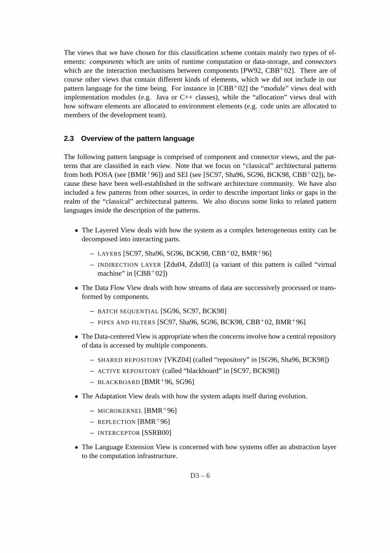
Figure 2 illustrates patterns and their relationships from the Layered, Data Flow, and Data-centered Views.
Layers
Pipes and Filters Shared Repository
alternative for separatinghigher-level from lower-level
responsibilities, also used internally
alternative for separatinghigher-level from lower-levelresponsibilities, also used internally
can be used to allowfor data sharingbetween filters
BlackboardActive Repository
variant when repositoryneeds to actively inform
subscribers
variant when no deterministicapproach to a solution is knownor feasible
can be used forcommunication between layers
usesImplicit Invocation
Batch Sequential
alternative whenstream-based
processing is needed
Indirection Layer
layer used for indirectionand add-on tasks
Figure 2: Overview: Patterns of the Layered, Data Flow and Data-centered Views
Pattern: Layers
Consider a system in which high-level components depend on low-level components to performtheir functionality, which further depend on even lower-level components and so on. Decouplingthe components in a vertical manner is crucial in order to support modifiability, portability,and reusability. On the other hand components also require some horizontal structuring that isorthogonal to their vertical subdivision.
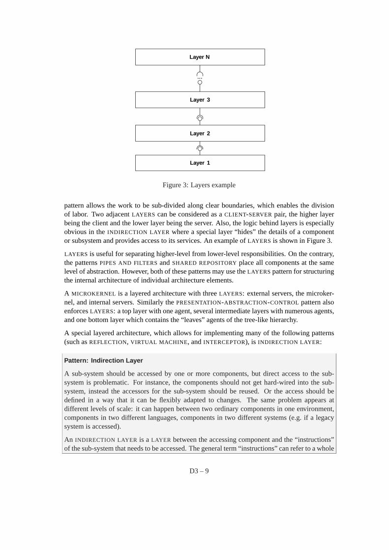
To achieve these goals, the system is structured intoLAYERS so that each layer provides a setof services to the layer above and uses the services of the layer below. Within eachLAYER allconstituent components work at the same level of abstraction and can interact through connec-tors. Between two adjacent layers a clearly defined interface is provided. In the pure form ofthe pattern, layers should not be by-passed: higher-level layers access lower-level layers onlythrough the layer beneath.
Each layer offers a dedicatedEXPLICIT INTERFACE [BH03] to the higher-level layers, whichremains stable, whereas internal implementation details can change. This way theLAYERS
D3 – 8
Layer 1
Layer 2
Layer 3
...
Layer N
Figure 3: Layers example
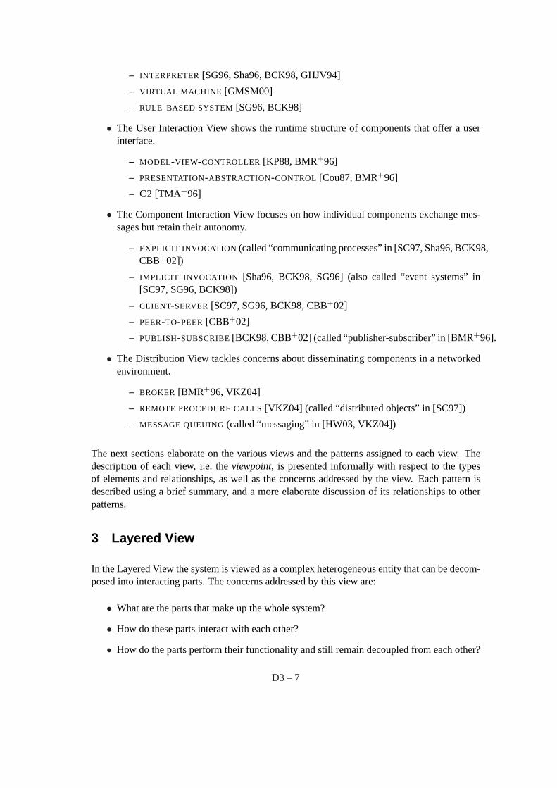
pattern allows the work to be sub-divided along clear boundaries, which enables the divisionof labor. Two adjacentLAYERS can be considered as aCLIENT-SERVERpair, the higher layerbeing the client and the lower layer being the server. Also, the logic behind layers is especiallyobvious in theINDIRECTION LAYER where a special layer “hides” the details of a componentor subsystem and provides access to its services. An example ofLAYERS is shown in Figure 3.
LAYERS is useful for separating higher-level from lower-level responsibilities. On the contrary,the patternsPIPES AND FILTERSandSHARED REPOSITORYplace all components at the samelevel of abstraction. However, both of these patterns may use theLAYERS pattern for structuringthe internal architecture of individual architecture elements.
A MICROKERNEL is a layered architecture with threeLAYERS: external servers, the microker-nel, and internal servers. Similarly thePRESENTATION-ABSTRACTION-CONTROL pattern alsoenforcesLAYERS: a top layer with one agent, several intermediate layers with numerous agents,and one bottom layer which contains the “leaves” agents of the tree-like hierarchy.
A special layered architecture, which allows for implementing many of the following patterns(such asREFLECTION, VIRTUAL MACHINE , andINTERCEPTOR), is INDIRECTION LAYER:
Pattern: Indirection Layer
A sub-system should be accessed by one or more components, but direct access to the sub-system is problematic. For instance, the components should not get hard-wired into the sub-system, instead the accessors for the sub-system should be reused. Or the access should bedefined in a way that it can be flexibly adapted to changes. The same problem appears atdifferent levels of scale: it can happen between two ordinary components in one environment,components in two different languages, components in two different systems (e.g. if a legacysystem is accessed).
An INDIRECTION LAYER is a LAYER between the accessing component and the “instructions”of the sub-system that needs to be accessed. The general term “instructions” can refer to a whole
D3 – 9
programming language, or an application programming interface (API) or the public interface(s)of a component or sub-system, or other conventions that accessing components must follow. TheINDIRECTION LAYER wraps all accesses to the relevant sub-system and should not be bypassed.The INDIRECTION LAYER can perform additional tasks while deviating invocations to the sub-system, such as converting or tracing the invocations.
The INDIRECTION LAYER can either be integrated to the sub-system (as in “virtual machine”[CBB+02]) or be an independent entity (as inADAPTER or FACADE [GHJV94]) that forwardsthe invocations to the sub-system. In both cases the accessing components are not aware ofthis, since theINDIRECTION LAYER aims at exactly that: hiding whatever it is that provides theservices.
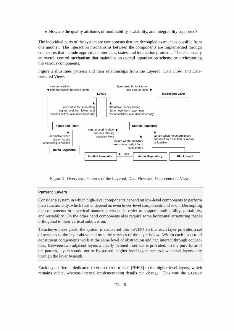
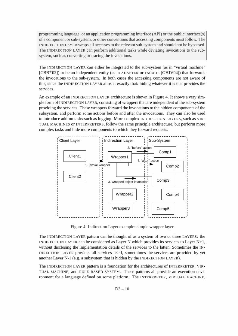
An example of anINDIRECTION LAYER architecture is shown in Figure 4. It shows a very sim-ple form ofINDIRECTION LAYER, consisting of wrappers that are independent of the sub-systemproviding the services. These wrappers forward the invocations to the hidden components of thesubsystem, and perform some actions before and after the invocations. They can also be usedto introduce add-on tasks such as logging. More complexINDIRECTION LAYERS, such asVIR-TUAL MACHINES or INTERPRETERS, follow the same principle architecture, but perform morecomplex tasks and hide more components to which they forward requests.
Client1
Client Layer
Client2
Sub-System
Comp2
Comp3
Comp4
Comp5
Wrapper2
Wrapper3
Comp1
Indirection Layer
1. invoke wrapper
2. "before" action
Wrapper14. "after" action
3. wrapped object invocation
Figure 4: Indirection Layer example: simple wrapper layer
The INDIRECTION LAYER pattern can be thought of as a system of two or threeLAYERS: theINDIRECTION LAYER can be considered as Layer N which provides its services to Layer N+1,without disclosing the implementation details of the services to the latter. Sometimes theIN-DIRECTION LAYER provides all services itself, somethimes the services are provided by yetanother Layer N-1 (e.g. a subsystem that is hidden by theINDIRECTION LAYER).
The INDIRECTION LAYER pattern is a foundation for the architectures ofINTERPRETER, VIR-TUAL MACHINE , and RULE-BASED SYSTEM. These patterns all provide an execution envi-ronment for a language defined on some platform. TheINTERPRETER, VIRTUAL MACHINE ,
D3 – 10
or RULE-BASED SYSTEM interpose anINDIRECTION LAYER between the instructions of thatlanguage and the instructions of the platform.
The REFLECTION pattern might also be implemented using anINDIRECTION LAYER, so thatthe latter provides the reflective capabilities of the components defined on top of it. Specifically,the INDIRECTION LAYER can intercept all invocations of the components, and thus can use thisinformation to record the current structure and behavior of the system. This information canthen be provided using a reflection API.
4 Data Flow View
In the Data Flow View the system is viewed as a number of subsequent transformations uponstreams of input data. The concerns addressed by this view are:
• What are the elements that perform the transformations?
• What are the elements that carry the streams of data?
• How are the two aforementioned types of elements connected to each other?
• How are the quality attributes of modifiability, reusability, and integrability supported?
The elements that perform the transformations are components that are independent of one an-other, and have input and output ports. The elements that carry the streams of data are connectorsand similarly have data-in and data-out roles. The relationships between these elements are at-tachments that connect input ports of components to data-out roles of connectors, and outputports of components to data-in roles of connectors.
Pattern: Batch Sequential
Consider a complex task that can be sub-divided into a number of smaller tasks, which can bedefined as a series of independent computations. This should not be realized by one monolithiccomponent because this component would be overly complex, and it would hinder modifiabilityand reusability.
In a BATCH SEQUENTIAL architecture the whole task is sub-divided into small processing steps,which are realized as separate, independent components. Each step runs to completion and thencalls the next sequential step until the whole task is fulfilled. During each step a batch of data isprocessed and sent as a whole to the next step.
BATCH SEQUENTIAL is a simple sequential data processing architectural pattern. It is usefulfor simple data flows, but entails severe overhead for starting the batch processes and trans-mitting data between them.PIPES AND FILTERSis more suitable for stream-oriented data-flowprocessing, where the filters incrementally transform their input streams into output streams.
D3 – 11

Pattern: Pipes and Filters
Consider as inBATCH SEQUENTIAL the case where a complex task can be sub-divided into anumber of smaller tasks, which can be defined as a series of independent computations. Addi-tionally the application processes streams of data, i.e. it transforms input data streams into outputdata streams. This functionality should not be realized by one monolithic component becausethis component would be overly complex, and it would hinder modifiability and reusability.Furthermore, different clients require different variations of the computations, for instance, theresults should be presented in different ways or different kinds of input data should be provided.To reach this goal, it must be possible to flexibly compose individual sub-tasks according to theclient’s demands.
In a PIPES AND FILTERSarchitecture a complex task is divided into several sequential sub-tasks. Each of these sub-tasks is implemented by a separate, independent component, a filter,which handles only this task. Filters have a number of inputs and a number of outputs and theyare connected flexibly using pipes but they are never aware of the identity of adjacent filters.Each pipe realizes a stream of data between two components. Each filter consumes and deliversdata incrementally, which maximizes the throughput of each individual filter, since filters canpotentially work in parallel. Pipes act as data buffers between adjacent filters. The use ofPIPES
AND FILTERS is advisable when little contextual information needs to be maintained betweenthe filter components and filters retain no state between invocations.PIPES AND FILTERScan beflexibly composed. However, sharing data between these components is expensive or inflexible.There are performance overheads for transferring data in pipes and data transformations, anderror handling is rather difficult.
An example ofPIPES AND FILTERSis shown in Figure 5. Forks/joins as well as feedback loopsare allowed in this pattern, but there is also a variant referred to as apipeline, that forbids both,i.e. has a strict linear topology.
Filter 1 Filter 2pipepipe
Filter 4 output
Filter 3
pipepipe
input
Figure 5: Pipes and filters example
In contrast toBATCH SEQUENTIAL, where there is no explicit abstraction for connectors, thePIPES AND FILTERSpattern considers the pipe connector to be of paramount importance for thetransfer of data streams. The key word inPIPES AND FILTERSis flexibility in connecting filtersthrough pipes in order to assemble custom configurations that solve specific problems. Also inPIPES AND FILTERSthere is a constant flow of data streams between the filters, while inBATCH
SEQUENTIAL, the processing steps are discrete in the sense that each step finishes before thenext step may commence.
D3 – 12
The pure form of thePIPES AND FILTERSpattern entails that only two adjacent filters canshare data through their pipe, but not non-adjacent filters. Therefore purePIPES AND FILTERS
is an alternative toLAYERS and SHARED REPOSITORIES, only if data sharing between non-adjacent processing tasks is not needed. On the other hand, more relaxed forms of thePIPES AND
FILTERS pattern can be combined with data-centered architectures likeSHARED REPOSITORY,ACTIVE REPOSITORY, or BLACKBOARD to allow for data-sharing between filters.PIPES AND
FILTERS can also be used for communication betweenLAYERS, if data flows through layers areneeded.
5 Data-centered View
In the Data-centered View the system is viewed as a persistent, shared data store that is accessedand modified by a number of elements. The concerns addressed by this view are:
• How is the shared data store created, accessed, and updated?
• How is data distributed?
• Is the data store passive or active, i.e. does it notify its accessors or are the accessorsresponsible of finding data of interest to them?
• How does the data store communicate with the elements that access it?
• Do the accessor elements communicate indirectly through the shared data or also directlywith each other?
• How are the quality attributes of scalability, modifiability, reusability, and integrabilitysupported?
The data store and the elements that access it are components. The data store is independent ofthe components, and the components are usually independent of one another. It is possible thatthere is more than one data store. The elements that transfer data written or read from the datastores are connectors that are attached to the data store(s) and the accessors.
Pattern: Shared Repository
Data needs to be shared between components. In sequential architectures likeLAYERS or PIPES
AND FILTERS the only way to share data between the components (layers or filters) is to passthe information along with the invocation, which might be inefficient for large data sets. Also itmight be inefficient, if the shared information varies from invocation to invocation because thecomponents’ interfaces must be prepared to transmit various kinds of data. Finally the long-termpersistence of the data requires a centralized data management.
In the SHARED REPOSITORYpattern one component of the system is used as a central datastore, accessed by all other independent components. ThisSHARED REPOSITORYoffers suitablemeans for accessing the data, for instance, a query API or language. TheSHARED REPOSITORY
must be scalable to meet the clients’ requirements, and it must ensure data consistency. It must
D3 – 13
handle problems of resource contention, for example by locking accessed data. TheSHARED
REPOSITORYmight also introduce transaction mechanisms.
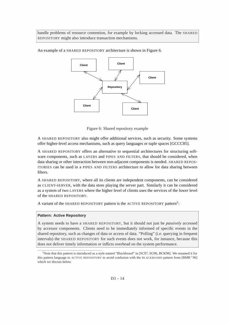
An example of aSHARED REPOSITORYarchitecture is shown in Figure 6.
Client
Repository
Client
Client
ClientClient
Figure 6: Shared repository example
A SHARED REPOSITORYalso might offer additional services, such as security. Some systemsoffer higher-level access mechanisms, such as query languages or tuple spaces [GCCC85].
A SHARED REPOSITORYoffers an alternative to sequential architectures for structuring soft-ware components, such asLAYERS andPIPES AND FILTERS, that should be considered, whendata sharing or other interaction between non-adjacent components is needed.SHARED REPOS-ITORIES can be used in aPIPES AND FILTERSarchitecture to allow for data sharing betweenfilters.
A SHARED REPOSITORY, where all its clients are independent components, can be consideredasCLIENT-SERVER, with the data store playing the server part. Similarly it can be consideredas a system of twoLAYERS where the higher level of clients uses the services of the lower levelof theSHARED REPOSITORY.
A variant of theSHARED REPOSITORYpattern is theACTIVE REPOSITORYpattern2:
Pattern: Active Repository
A system needs to have aSHARED REPOSITORY, but it should not just bepassivelyaccessedby accessor components. Clients need to be immediately informed of specific events in theshared repository, such as changes of data or access of data. “Polling” (i.e. querying in frequentintervals) theSHARED REPOSITORYfor such events does not work, for instance, because thisdoes not deliver timely information or inflicts overhead on the system performance.
2Note that this pattern is introduced as a style named “Blackboard” in [SC97, SG96, BCK98]. We renamed it forthis pattern language toACTIVE REPOSITORYto avoid confusion with theBLACKBOARD pattern from [BMR+96]which we discuss below.
D3 – 14
An ACTIVE REPOSITORYis aSHARED REPOSITORYthat is “active” in the sense that it informsa number of subscribers of specific events that happen in the shared repository. TheACTIVE
REPOSITORYmaintains a registry of clients and informs them through appropriate notificationmechanisms.
The notification mechanism can be realized using ordinaryEXPLICIT INVOCATIONS, but inmost casesIMPLICIT INVOCATIONS, such asPUBLISH-SUBSCRIBE, are more appropriate.
Another variant of theSHARED REPOSITORYpattern is theBLACKBOARD pattern, which isappropriate when aSHARED REPOSITORYis used in an immature domain in which no deter-ministic approach to a solution is known or feasible.
Pattern: Blackboard
Consider the case where aSHARED REPOSITORYis needed for the shared data of a computation,but no deterministic solution strategies are known. Examples are image recognition or speechrecognition applications. However, it should be possible to realize a solution for these types ofapplications.
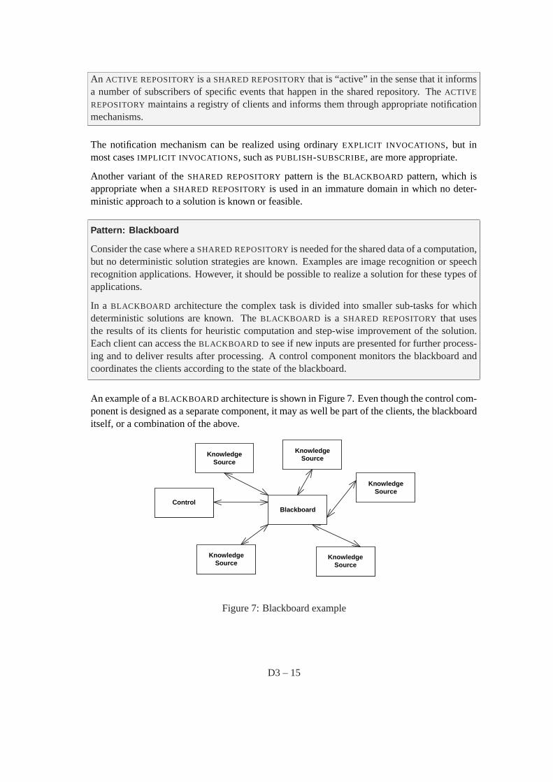
In a BLACKBOARD architecture the complex task is divided into smaller sub-tasks for whichdeterministic solutions are known. TheBLACKBOARD is a SHARED REPOSITORYthat usesthe results of its clients for heuristic computation and step-wise improvement of the solution.Each client can access theBLACKBOARD to see if new inputs are presented for further process-ing and to deliver results after processing. A control component monitors the blackboard andcoordinates the clients according to the state of the blackboard.
An example of aBLACKBOARD architecture is shown in Figure 7. Even though the control com-ponent is designed as a separate component, it may as well be part of the clients, the blackboarditself, or a combination of the above.
KnowledgeSource
Blackboard
KnowledgeSource
KnowledgeSource
KnowledgeSource
Control
KnowledgeSource
Figure 7: Blackboard example
D3 – 15
6 Adaptation View
In the Adaptation View the system is viewed as a core part that remains invariable and an adapt-able part that either changes over time or in different versions of a system. The concerns ad-dressed by this view are:
• How can a system adapt better to evolution over time or to multiple different versions ofa basic architecture?
• What is the system functionality that is more likely to change and what will possiblyremain invariable?
• How do the invariable parts communicate with the adaptable parts?
• How are the quality attributes of modifiability, reusability, evolvability, and integrabilitysupported?
The two basic types of elements in this view are the invariable components and the adaptablecomponents (these are often called variation points). These two kinds of components commu-nicate with each other through connectors that have clearly-specified interfaces. Note that somekinds of connectors are adaptable as well, i.e. they are also used as variation points.
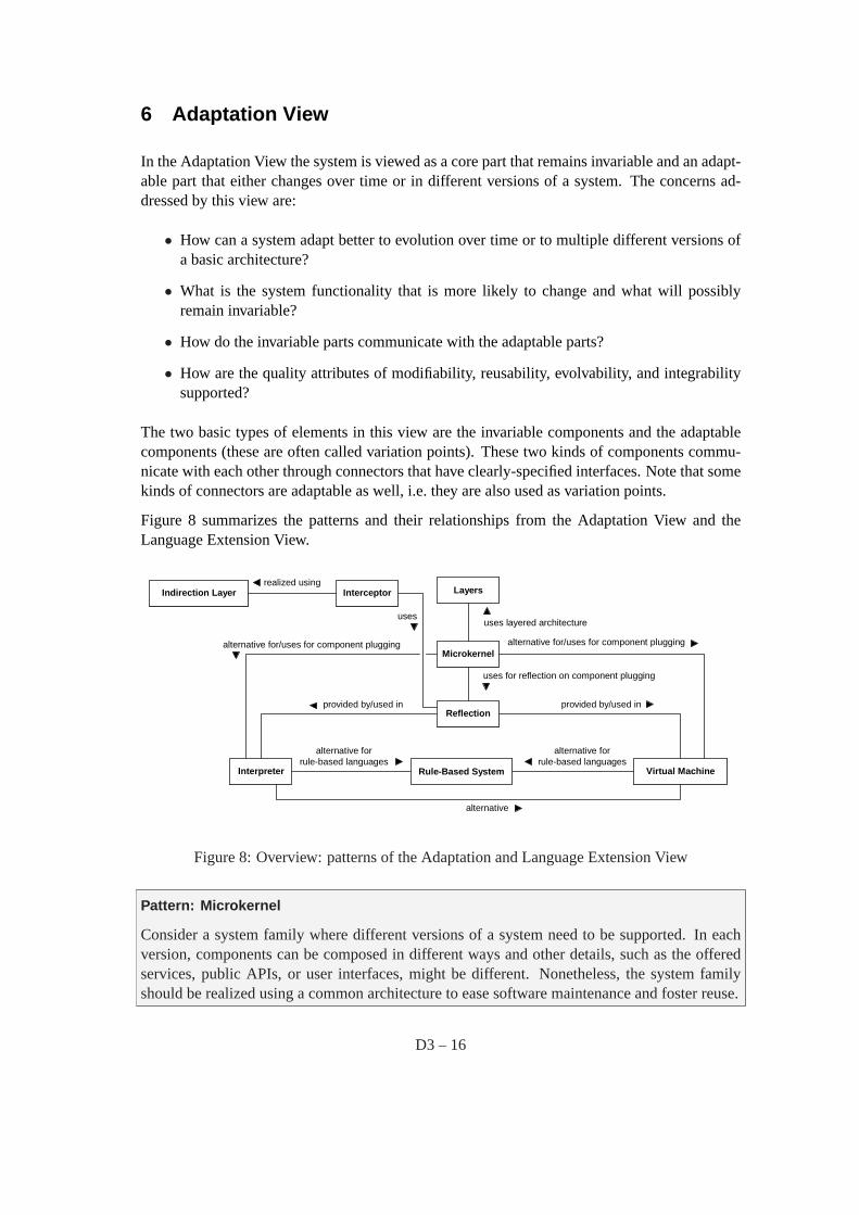
Figure 8 summarizes the patterns and their relationships from the Adaptation View and theLanguage Extension View.
Microkernel
Layers
uses layered architecture
Interpreter Rule-Based System Virtual Machine
Reflectionprovided by/used in
alternative forrule-based languages
alternative
alternative forrule-based languages
provided by/used in
uses for reflection on component plugging
alternative for/uses for component plugging alternative for/uses for component plugging
InterceptorIndirection Layerrealized using
uses
Figure 8: Overview: patterns of the Adaptation and Language Extension View
Pattern: Microkernel
Consider a system family where different versions of a system need to be supported. In eachversion, components can be composed in different ways and other details, such as the offeredservices, public APIs, or user interfaces, might be different. Nonetheless, the system familyshould be realized using a common architecture to ease software maintenance and foster reuse.
D3 – 16
A MICROKERNEL realizes services that all systems, derived from the system family, need anda plug-and-play infrastructure for the system-specific services. Internal servers (not visible toclients) are used to realize version-specific services and they are only accessed through theMI -CROKERNEL. On the other hand, external servers offer APIs and user interfaces to clients byusing theMICROKERNEL. External servers are the only way for clients to access theMICRO-KERNEL architecture.
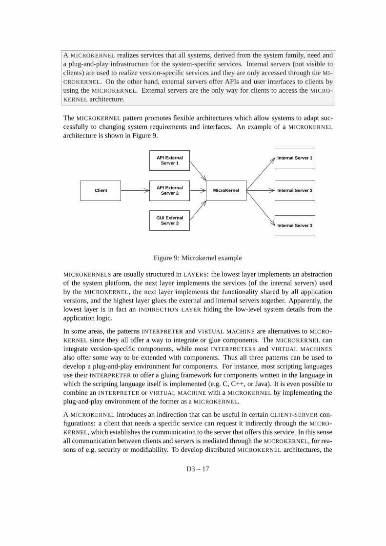
The MICROKERNEL pattern promotes flexible architectures which allow systems to adapt suc-cessfully to changing system requirements and interfaces. An example of aMICROKERNEL
architecture is shown in Figure 9.
Internal Server 1
GUI ExternalServer 3
API ExternalServer 1
ClientAPI External
Server 2MicroKernel Internal Server 2
Internal Server 3
Figure 9: Microkernel example
MICROKERNELSare usually structured inLAYERS: the lowest layer implements an abstractionof the system platform, the next layer implements the services (of the internal servers) usedby the MICROKERNEL, the next layer implements the functionality shared by all applicationversions, and the highest layer glues the external and internal servers together. Apparently, thelowest layer is in fact anINDIRECTION LAYER hiding the low-level system details from theapplication logic.
In some areas, the patternsINTERPRETERandVIRTUAL MACHINE are alternatives toMICRO-KERNEL since they all offer a way to integrate or glue components. TheMICROKERNEL canintegrate version-specific components, while mostINTERPRETERSand VIRTUAL MACHINES
also offer some way to be extended with components. Thus all three patterns can be used todevelop a plug-and-play environment for components. For instance, most scripting languagesuse theirINTERPRETERto offer a gluing framework for components written in the language inwhich the scripting language itself is implemented (e.g. C, C++, or Java). It is even possible tocombine anINTERPRETERor VIRTUAL MACHINE with a MICROKERNEL by implementing theplug-and-play environment of the former as aMICROKERNEL.
A MICROKERNEL introduces an indirection that can be useful in certainCLIENT-SERVERcon-figurations: a client that needs a specific service can request it indirectly through theMICRO-KERNEL, which establishes the communication to the server that offers this service. In this senseall communication between clients and servers is mediated through theMICROKERNEL, for rea-sons of e.g. security or modifiability. To develop distributedMICROKERNEL architectures, the
D3 – 17
MICROKERNEL can be combined with theBROKER pattern to hide the communication detailsbetween clients that request services and servers that implement them.
For all environments that support plug-and-play of components,REFLECTION is useful becauseit allows to find out which components are currently composed in which way.
Pattern: Reflection
Software systems constantly evolve and change over the time, and unanticipated changes areoften required. It is hard to automatically cope with changes that are not foreseen.
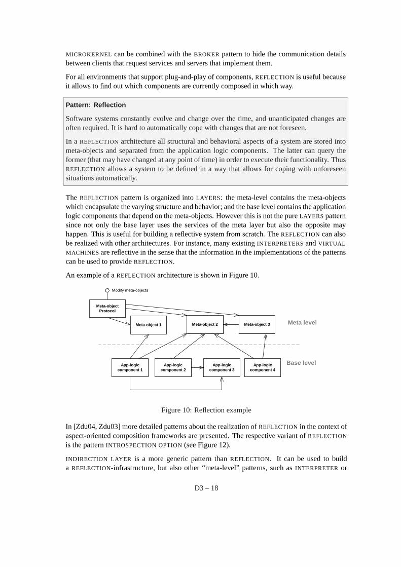
In a REFLECTION architecture all structural and behavioral aspects of a system are stored intometa-objects and separated from the application logic components. The latter can query theformer (that may have changed at any point of time) in order to execute their functionality. ThusREFLECTION allows a system to be defined in a way that allows for coping with unforeseensituations automatically.
The REFLECTION pattern is organized intoLAYERS: the meta-level contains the meta-objectswhich encapsulate the varying structure and behavior; and the base level contains the applicationlogic components that depend on the meta-objects. However this is not the pureLAYERS patternsince not only the base layer uses the services of the meta layer but also the opposite mayhappen. This is useful for building a reflective system from scratch. TheREFLECTIONcan alsobe realized with other architectures. For instance, many existingINTERPRETERSandVIRTUAL
MACHINES are reflective in the sense that the information in the implementations of the patternscan be used to provideREFLECTION.
An example of aREFLECTIONarchitecture is shown in Figure 10.
Meta level
Base level
Modify meta-objects
Meta-object 1
App-logiccomponent 1
Meta-object 2 Meta-object 3
App-logiccomponent 4
App-logiccomponent 3
App-logiccomponent 2
Meta-objectProtocol
Figure 10: Reflection example
In [Zdu04, Zdu03] more detailed patterns about the realization ofREFLECTION in the context ofaspect-oriented composition frameworks are presented. The respective variant ofREFLECTION
is the patternINTROSPECTION OPTION(see Figure 12).
INDIRECTION LAYER is a more generic pattern thanREFLECTION. It can be used to builda REFLECTION-infrastructure, but also other “meta-level” patterns, such asINTERPRETERor
D3 – 18
VIRTUAL MACHINE .
In cases where we need an adaptableframeworkto accommodate future services, theINTER-CEPTORpattern is appropriate:
Pattern: Interceptor
A framework offers a number of reusable services to the applications that extend it. Theseservices need to be updated in the future as the application domain matures and they should stillbe offered by the framework, so that the application developers do not need to re-implementthem. Furthermore, the framework developer cannot predict all such future services at the pointof time where the framework is created, while application developers may not be able to addunanticipated extensions to the framework, in case e.g. that the framework is a black-box.
An INTERCEPTORis a mechanism for transparently updating the services offered by the frame-work in response to incoming events. An application can register with the framework any num-ber of INTERCEPTORSthat implement new services. The framework facilitates this registrationthrough dispatchers that assign events toINTERCEPTORS. The framework also provides the ap-plications with the means to introspect on the framework’s behavior in order to properly handlethe events.
The INTERCEPTORpattern can be realized using anINDIRECTION LAYER or one of its variants,such asINTERPRETERor VIRTUAL MACHINE . The incoming events are therefore re-routedthrough theINDIRECTION LAYER that consists of severalINTERCEPTORS, before they are dis-patched to the intended receiver.
INTERCEPTORcan use aREFLECTIONmechanism in order to query the framework and retrievethe necessary information to process incoming events.
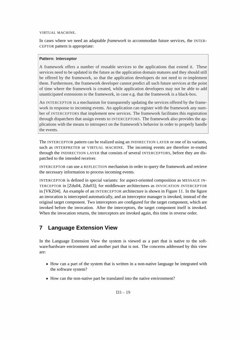
INTERCEPTORis defined in special variants: for aspect-oriented composition asMESSAGE IN-TERCEPTORin [Zdu04, Zdu03]; for middleware architectures asINVOCATION INTERCEPTOR
in [VKZ04]. An example of anINTERCEPTORarchitecture is shown in Figure 11. In the figurean invocation is intercepted automatically, and an interceptor manager is invoked, instead of theoriginal target component. Two interceptors are configured for the target component, which areinvoked before the invocation. After the interceptors, the target component itself is invoked.When the invocation returns, the interceptors are invoked again, this time in reverse order.
7 Language Extension View
In the Language Extension View the system is viewed as a part that is native to the soft-ware/hardware environment and another part that is not. The concerns addressed by this vieware:
• How can a part of the system that is written in a non-native language be integrated withthe software system?
• How can the non-native part be translated into the native environment?
D3 – 19
Client
Client Layer
Interceptor1
Comp
InterceptorManager
Indirection Layer
Interceptor2
3. before "aMethod"
6. after "aMethod"
5. after "aMethod"
2. before "aMethod"
1. invoke "aMethod" on Comp 4. invoke "aMethod"
Figure 11: Interceptor example
• How are the quality attribute of portability and modifiability supported?
The native part of the application and the non-native part are components. These communicateindirectly through another type of component, an interpreter component that “translates” the lat-ter into the former. The connectors between these components are data that contain the programinstructions in the non-native language, as well as the internal state of the non-native part.
Pattern: Interpreter
A language syntax and grammar needs to be parsed and interpreted within an application. Thelanguage needs to be interpreted at runtime (i.e. using a compiler is not feasible).
An INTERPRETERfor the language is provided, which provides both parsing facilities and anexecution environment. The program that needs to be interpreted is provided in form of scriptswhich are interpreted at runtime. These scripts are portable to each platform realization of theINTERPRETER. For instance, theINTERPRETERcan define a class per grammar rule of thelanguage. The parser of the interpreter parses language instructions according to these rules andinvokes the interpretation classes. Many more complexINTERPRETERarchitectures exist.
SomeINTERPRETERSuse optimizations like on-the-fly byte-code compilers. They thus realizeinternally elements of aVIRTUAL MACHINE . Note that anINTERPRETERis different to aVIR-TUAL MACHINE because it allows for runtime interpretation of scripts, whereas theVIRTUAL
MACHINE architecture depends on compilation before runtime:
Pattern: Virtual Machine
An efficient execution environment for a programming language is needed. The architectureshould facilitate portability, code optimizations, and native machine code generation. Runtimeinterpretation of the language is not necessarily required.
D3 – 20
A VIRTUAL MACHINE defines a simple machine architecture on which not machine code butan intermediate form called the byte-code can be executed. The language is compiled into thatbyte-code. TheVIRTUAL MACHINE can be realized on different platforms, so that the byte-codecan be portable between these platforms. TheVIRTUAL MACHINE redirects invocations from abyte-code layer into an implementation layer for the commands of the byte-code.
An alternative toINTERPRETERSand VIRTUAL MACHINES , when rule-based or logical lan-guages are needed, is aRULE-BASED SYSTEM:
Pattern: Rule-Based System
Logical problems are hard to express elegantly in imperative languages that are typically used inINTERPRETERSandVIRTUAL MACHINES . Consider for instance an expert system that providesthe knowledge of an expert or a set of constraints. In imperative languages these are expressedby nested if-statements or similar constructs which are rather hard to understand.
A RULE-BASED SYSTEM offers an alternative for expressing such problems in a system. Itconsists mainly of three things: facts, rules, and an engine that acts on them. Rules representknowledge in form of a condition and associated actions. Facts represent data. ARULE-BASED
SYSTEMapplies its rules to the known facts. The actions of a rule might assert new facts, which,in turn, trigger other rules.
As mentioned beforeINDIRECTION LAYER is the architectural foundation forINTERPRETER,VIRTUAL MACHINE , andRULE-BASED SYSTEM, since either the instructions of the languageor the byte-code are re-directed dynamically (at runtime). We do not show component andconnector diagrams for these three patterns, since their structure is trivially similar to that of anINDIRECTION LAYER.
In [Zdu04, Zdu03] a number of static alternatives for building language extensions are presentedin the context of aspect-oriented composition frameworks. These, for instance, manipulate theparse tree (PARSE TREE INTERPRETER) or byte-code (BYTE-CODE MANIPULATOR) of a lan-guage. The relationships to these patterns for aspect-oriented composition are shown in Figure12.
8 User Interaction View
In the User Interaction View the system is viewed as a part that represents the user interfaceand a part that contains the application logic, associated with the user interface. The concernsaddressed by this view are:
• What is the data and the application logic that is associated to the user interface?
• How is the user interface decoupled from the application logic?
• How are the quality attributes of usability, modifiability, and reusability supported?
D3 – 21
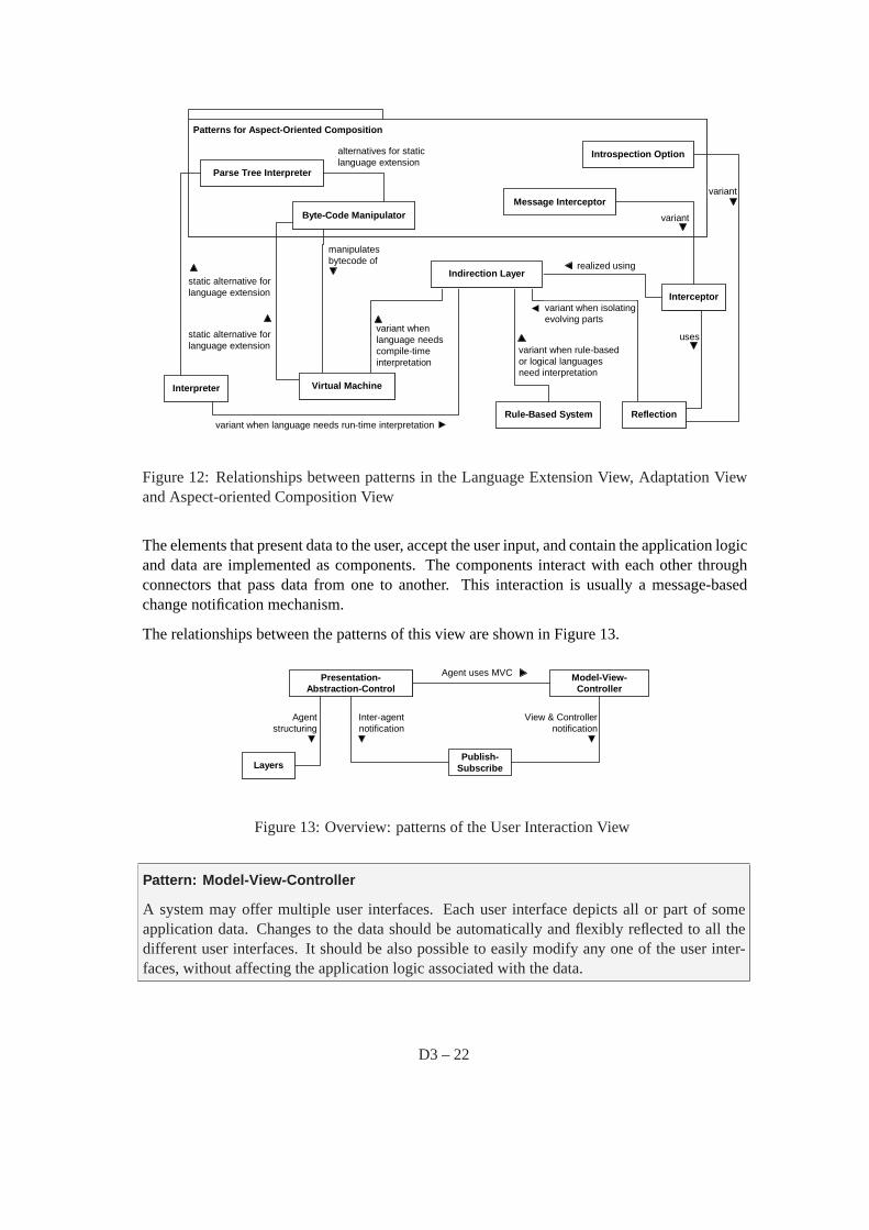
Patterns for Aspect-Oriented Composition
Interpreter
Rule-Based Systemvariant when language needs run-time interpretation
variant when rule-basedor logical languagesneed interpretation
variant whenlanguage needscompile-timeinterpretation
variant when isolatingevolving parts
Reflection
Parse Tree Interpreter
Byte-Code Manipulator
alternatives for staticlanguage extension
Introspection Option
variant
Interceptor
Message Interceptor
variant
realized using
usesstatic alternative forlanguage extension
static alternative forlanguage extension
manipulatesbytecode of
Virtual Machine
Indirection Layer
Figure 12: Relationships between patterns in the Language Extension View, Adaptation Viewand Aspect-oriented Composition View
The elements that present data to the user, accept the user input, and contain the application logicand data are implemented as components. The components interact with each other throughconnectors that pass data from one to another. This interaction is usually a message-basedchange notification mechanism.
The relationships between the patterns of this view are shown in Figure 13.
Presentation-Abstraction-Control
Model-View-Controller
Agent uses MVC
Publish-Subscribe
Inter-agentnotification
View & Controllernotification
Layers
Agentstructuring
Figure 13: Overview: patterns of the User Interaction View
Pattern: Model-View-Controller
A system may offer multiple user interfaces. Each user interface depicts all or part of someapplication data. Changes to the data should be automatically and flexibly reflected to all thedifferent user interfaces. It should be also possible to easily modify any one of the user inter-faces, without affecting the application logic associated with the data.
D3 – 22
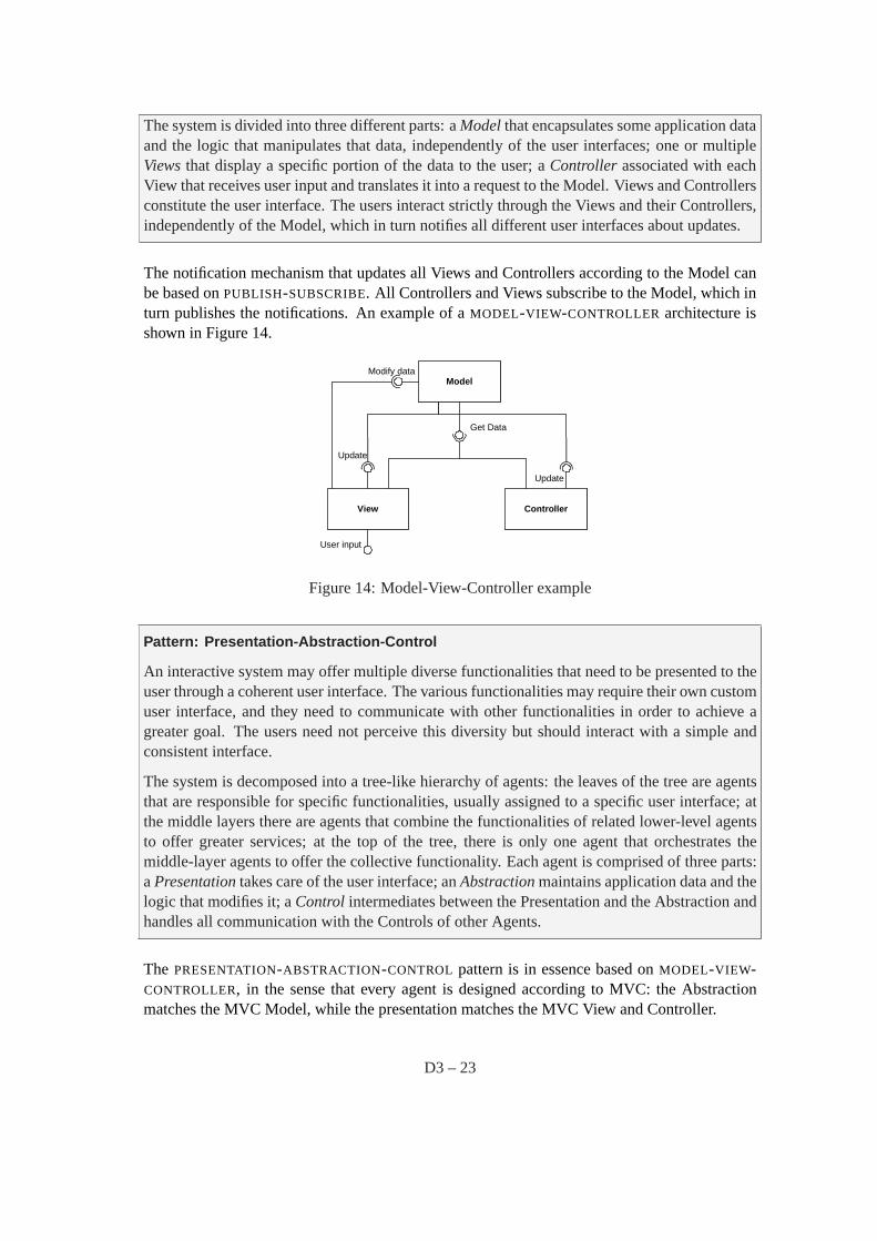
The system is divided into three different parts: aModelthat encapsulates some application dataand the logic that manipulates that data, independently of the user interfaces; one or multipleViewsthat display a specific portion of the data to the user; aController associated with eachView that receives user input and translates it into a request to the Model. Views and Controllersconstitute the user interface. The users interact strictly through the Views and their Controllers,independently of the Model, which in turn notifies all different user interfaces about updates.
The notification mechanism that updates all Views and Controllers according to the Model canbe based onPUBLISH-SUBSCRIBE. All Controllers and Views subscribe to the Model, which inturn publishes the notifications. An example of aMODEL-VIEW-CONTROLLER architecture isshown in Figure 14.
View Controller
ModelModify data
User input
Get Data
Update
Update
Figure 14: Model-View-Controller example
Pattern: Presentation-Abstraction-Control
An interactive system may offer multiple diverse functionalities that need to be presented to theuser through a coherent user interface. The various functionalities may require their own customuser interface, and they need to communicate with other functionalities in order to achieve agreater goal. The users need not perceive this diversity but should interact with a simple andconsistent interface.
The system is decomposed into a tree-like hierarchy of agents: the leaves of the tree are agentsthat are responsible for specific functionalities, usually assigned to a specific user interface; atthe middle layers there are agents that combine the functionalities of related lower-level agentsto offer greater services; at the top of the tree, there is only one agent that orchestrates themiddle-layer agents to offer the collective functionality. Each agent is comprised of three parts:aPresentationtakes care of the user interface; anAbstractionmaintains application data and thelogic that modifies it; aControl intermediates between the Presentation and the Abstraction andhandles all communication with the Controls of other Agents.
The PRESENTATION-ABSTRACTION-CONTROL pattern is in essence based onMODEL-VIEW-CONTROLLER, in the sense that every agent is designed according to MVC: the Abstractionmatches the MVC Model, while the presentation matches the MVC View and Controller.
D3 – 23
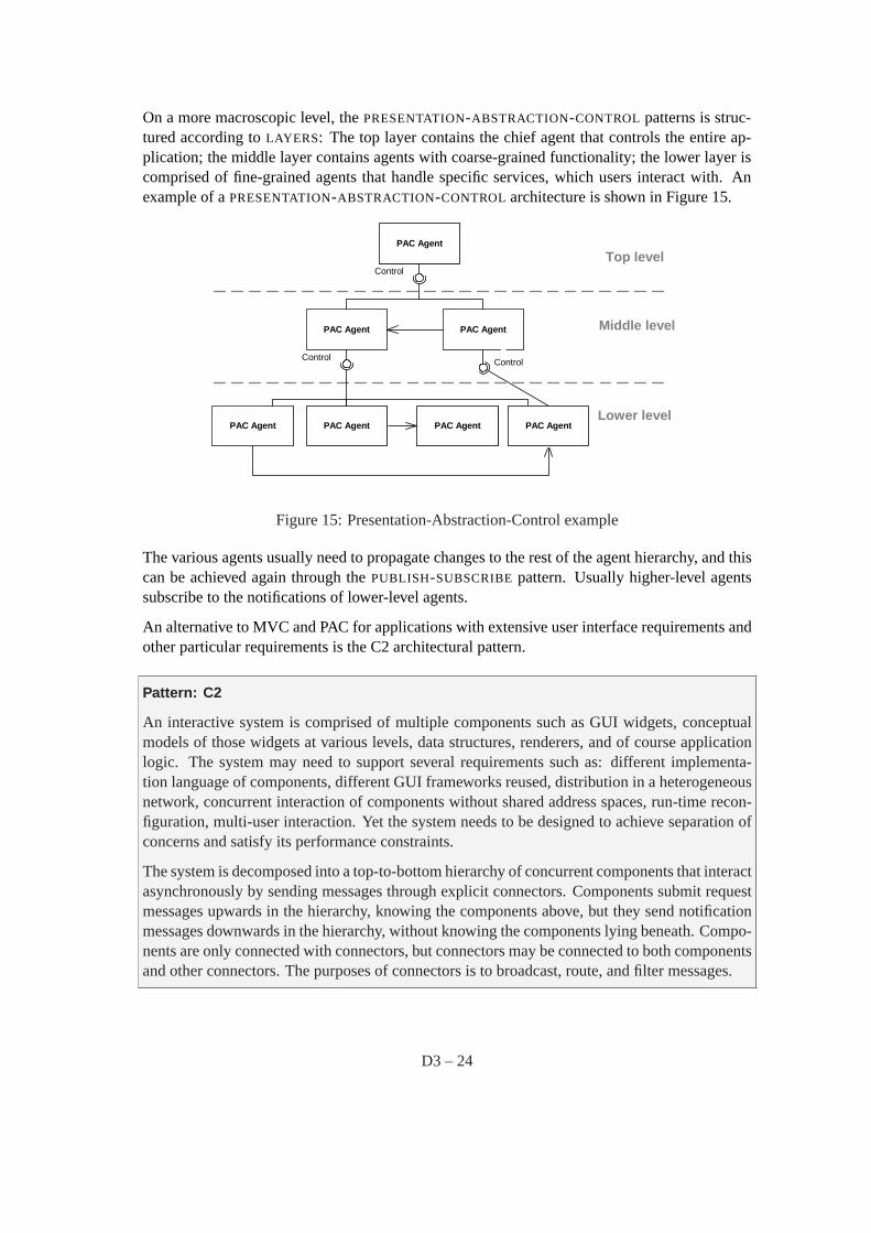
On a more macroscopic level, thePRESENTATION-ABSTRACTION-CONTROL patterns is struc-tured according toLAYERS: The top layer contains the chief agent that controls the entire ap-plication; the middle layer contains agents with coarse-grained functionality; the lower layer iscomprised of fine-grained agents that handle specific services, which users interact with. Anexample of aPRESENTATION-ABSTRACTION-CONTROL architecture is shown in Figure 15.
PAC Agent
PAC Agent PAC Agent Middle level
Lower level
PAC Agent
Top level
Control Control
PAC Agent PAC AgentPAC Agent
Control
Figure 15: Presentation-Abstraction-Control example
The various agents usually need to propagate changes to the rest of the agent hierarchy, and thiscan be achieved again through thePUBLISH-SUBSCRIBEpattern. Usually higher-level agentssubscribe to the notifications of lower-level agents.
An alternative to MVC and PAC for applications with extensive user interface requirements andother particular requirements is the C2 architectural pattern.
Pattern: C2
An interactive system is comprised of multiple components such as GUI widgets, conceptualmodels of those widgets at various levels, data structures, renderers, and of course applicationlogic. The system may need to support several requirements such as: different implementa-tion language of components, different GUI frameworks reused, distribution in a heterogeneousnetwork, concurrent interaction of components without shared address spaces, run-time recon-figuration, multi-user interaction. Yet the system needs to be designed to achieve separation ofconcerns and satisfy its performance constraints.
The system is decomposed into a top-to-bottom hierarchy of concurrent components that interactasynchronously by sending messages through explicit connectors. Components submit requestmessages upwards in the hierarchy, knowing the components above, but they send notificationmessages downwards in the hierarchy, without knowing the components lying beneath. Compo-nents are only connected with connectors, but connectors may be connected to both componentsand other connectors. The purposes of connectors is to broadcast, route, and filter messages.
D3 – 24

An example of aC2 architecture with four components in three layers, and two connectors thatdelimit the layers, is shown in Figure 16.
CompA
ConnA
CompCCompB
ConnB
CompD
requests notifications
Figure 16: C2 example
TheC2top-to-bottom hierarchy resembles the form of aLAYERS architecture in an upside-downorder. AC2 component that belongs to a given layer, uses the services of the layers above it byinvoking services on them and provides services to the layers below it by sending notificationsto them.
Since theC2 pattern providessubstrate independence[TMA +96], isolating a component fromthe components underneath it, the layer where a component is placed is in essence anINDIREC-TION LAYER.
The interaction between theC2 components takes place through asynchronous message ex-change, thus utilizing anIMPLICIT INVOCATION mechanism, and specifically callbacks, e.g.PUBLISH-SUBSCRIBE.
9 Component Interaction View
In the Component Interaction View the system is viewed as a number of independent compo-nents that interact with each other in the context of a system. The concerns addressed by thisview are:
• How do the independent components interact with each other?
• How are the individual components decoupled from each other?
• How are the quality attributes of modifiability and integrability supported?
D3 – 25
The components retain their independence, since they merely exchange data but do not directlycontrol each other. The components interact with each other through connectors that pass datafrom one to another. This interaction can be performed synchronously or asynchronously andcan be message-based or through direct calls. This view is closely connected to the distributedview, since the independent components might be distributed in various network nodes or pro-cesses.
The two major patterns in this view differentiate whether the components interact through ex-plicit or implicit invocations3:
Pattern: Explicit Invocation
Consider a component, the client, which needs to invoke a service defined in another component,the supplier. Coupling the client with the supplier in various ways is not only harmless butoften desirable. For example the client must know the exact network location of the componentwhich offers the service in order to improve performance; or the client must always initiatethe invocation itself; or the client must block, waiting for the result of the invocation, beforeproceeding with its business; or the topology of the interacting clients and suppliers is knownbeforehand and must remain fixed. How can these two components interact?
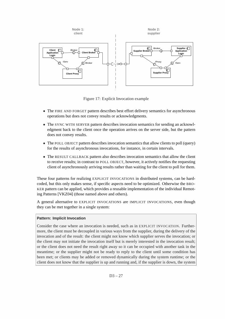
An EXPLICIT INVOCATION allows a client to invoke services on a supplier, by coupling them invarious respects. The decisions that concern the coupling (e.g. network location of the supplier)are known at design-time. The client provides these design decisions together with the servicename and parameters to theEXPLICIT INVOCATION mechanism, when initiating the invocation.The EXPLICIT INVOCATION mechanism performs the invocations and delivers the result to theclient as soon as it is computed. TheEXPLICIT INVOCATION mechanism may be part of theclient and the server or may exist as an independent component.
An example of anEXPLICIT INVOCATION architecture is shown in Figure 17, where theEX-PLICIT INVOCATION mechanism is implemented with the help of aBROKER and aPROXY, aspart of both the client and the supplier.
During theEXPLICIT INVOCATION the identification of the service supplier, can be realized, forinstance by using the patternOBJECT ID [VKZ04]. The client also knows the location of theservice supplier, and furthermore, in some systems, the service supplier needs to know about thelocation of the client, so that the result can be sent back. This can be achieved byOBJECT IDS
enriched with location information, as mandated by the patternABSOLUTE OBJECT REFERENCE
[VKZ04].
There are two main variants ofEXPLICIT INVOCATIONS: synchronous, explicit invocations andasynchronous, explicit invocations. In a synchronous invocation, the client blocks until the resultis available. In an asynchronous invocation, the client continues with its work immediately, andthe result is delivered at a later point, after it is computed. There are four patterns that describedifferent variants of asynchronous invocations for distributed systems [VKZ04]:
3Note that in [BCK98] anEXPLICIT INVOCATION is given the opposite meaning as it is considered a sub-patternof the EVENT SYSTEMSpattern. However we have chosen this name to show the contrast between componentsexplicitly (e.g. direct method call) and implicitly (e.g. events) invoking each other.
D3 – 26
Node 1:client
Node 2:supplier
ClientApplication
Logic
SupplierApplication
Logic
IServ
Client Proxy
IServ
Supplier Proxy
Client BrokerSupplier Broker
IProxyIBroker
IBrokerIBroker
Figure 17: Explicit Invocation example
• TheFIRE AND FORGETpattern describes best effort delivery semantics for asynchronousoperations but does not convey results or acknowledgments.
• TheSYNC WITH SERVERpattern describes invocation semantics for sending an acknowl-edgment back to the client once the operation arrives on the server side, but the patterndoes not convey results.
• ThePOLL OBJECTpattern describes invocation semantics that allow clients to poll (query)for the results of asynchronous invocations, for instance, in certain intervals.
• TheRESULT CALLBACK pattern also describes invocation semantics that allow the clientto receive results; in contrast toPOLL OBJECT, however, it actively notifies the requestingclient of asynchronously arriving results rather than waiting for the client to poll for them.
These four patterns for realizingEXPLICIT INVOCATIONS in distributed systems, can be hard-coded, but this only makes sense, if specific aspects need to be optimized. Otherwise theBRO-KER pattern can be applied, which provides a reusable implementation of the individual Remot-ing Patterns [VKZ04] (those named above and others).
A general alternative toEXPLICIT INVOCATIONS are IMPLICIT INVOCATIONS, even thoughthey can be met together in a single system:
Pattern: Implicit Invocation
Consider the case where an invocation is needed, such as inEXPLICIT INVOCATION. Further-more, the client must be decoupled in various ways from the supplier, during the delivery of theinvocation and of the result: the client might not know which supplier serves the invocation; orthe client may not initiate the invocation itself but is merely interested in the invocation result;or the client does not need the result right away so it can be occupied with another task in themeantime; or the supplier might not be ready to reply to the client until some condition hasbeen met; or clients may be added or removed dynamically during the system runtime; or theclient does not know that the supplier is up and running and, if the supplier is down, the system
D3 – 27
should suspend the invocation until the supplier is up again; or the client and the supplier arepart of dissimilar systems and thus the invocation must be transformed, queued, or otherwisemanipulated during delivery. How can such additional requirements during delivery be met?
In the IMPLICIT INVOCATION pattern the invocation is not performed explicitly from client tosupplier, but indirectly and rather randomly through a special mechanism such asPUBLISH-SUBSCRIBE, MESSAGE QUEUING, or broadcast, that decouples clients from suppliers. All ad-ditional requirements for invocation delivery are handled by theIMPLICIT INVOCATION mech-anism during the delivery of the invocation.
An example of implicit invocation is the synchronization between Model, View, and Controllerin the MODEL-VIEW-CONTROLLER pattern, as depicted in Figure 15. The Model notifies itsViews and Controllers whenever its data have been changed, and so Views and Controllersimplicitly invoke the Model to get the updated data. The Views and Controllers are decoupledfrom the Model, since they do not initiate the invocation, but the Model does it when it acceptsan certain event. Models and Controllers may also be added and removed dynamically.
IMPLICIT INVOCATION can be both synchronous and asynchronous as canEXPLICIT INVOCA-TION, meaning that the client can either block or not, waiting for the invocation result. HoweverIMPLICIT INVOCATIONS are most often asynchronous, in contrast toEXPLICIT INVOCATIONS,which are usually synchronous. Thus the aforementioned patterns for asynchronous result han-dling should be used forIMPLICIT INVOCATION as well. An even more prominent contrastbetween them is that inEXPLICIT INVOCATION the invocation is always deterministic fromclient to supplier, while inIMPLICIT INVOCATION the trigger happens randomly (e.g. throughan event) and not necessarily initiated by a client (e.g. by the producer inPUBLISH-SUBSCRIBE).
Same as inEXPLICIT INVOCATION, distributedIMPLICIT INVOCATION usually uses aBRO-KER to hide the details of network communication and allow the components to contain onlytheir application logic. Note that anIMPLICIT INVOCATION mechanism decouples clients fromsuppliers, while theBROKER pattern decouples both from the communication infrastructure.
There are differentIMPLICIT INVOCATION variants, with respect to the tasks performed dur-ing the delivery of the invocation. For instance, in a broadcast mechanism the location of theinvocation receiver is unknown to the client, since the invocation is broadcast through the net-work. This variant is used, e.g. for looking up the initial reference in aPEER-TO-PEERsystem.An event system realizesPUBLISH-SUBSCRIBE, in order to decouple producers and consumersof data. TheMESSAGE QUEUINGpattern queues invocations and results to increase deliveryreliability, handle temporal outages of the supplier, and perform other tasks.
Among the implicit and explicit invocation patterns and their variants, only the synchronousvariant ofEXPLICIT INVOCATION can align a result unambiguously to an invocation, becausethe client blocks on the result. For all other cases – when invocations are performed asyn-chronously, it is possible that one client sends multiple invocations after another, and resultsfor these invocations arrive in a different order than the invocations. Because the same clientperforms the invocations, theOBJECT ID of the client cannot be used for aligning a result toan invocation. AnASYNCHRONOUS COMPLETION TOKEN[SSRB00] contains information thatidentifies the individual invocation and perhaps also other information such as a behavior to beexecuted in the client when the result is processed. TheASYNCHRONOUS COMPLETION TO-
D3 – 28
KEN is sent along with each asynchronous invocation of a client, and the service supplier sendsit back with the result. Thus the client can use this information to align the result to the invo-cation. TheASYNCHRONOUS COMPLETION TOKENis used inIMPLICIT INVOCATIONS andasynchronousEXPLICIT INVOCATION to align invocations to incoming results.
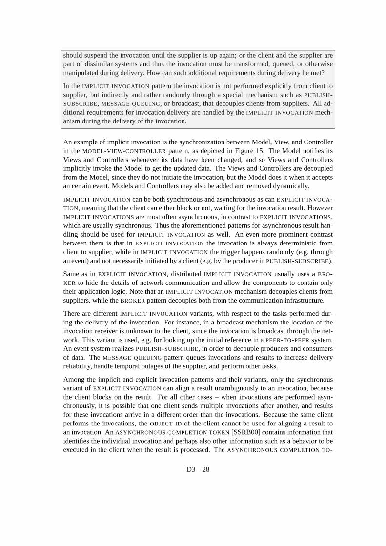
Figure 18 shows the relations ofIMPLICIT INVOCATION and EXPLICIT INVOCATION, whileFigure 19 gives an overview of all the patterns for component interaction as well as distribution.
Patterns for Networked Objects (POSA2)
Explict Invocation Implicit Invocationalternatives
Asynchronous Completion Token
result alignment forasynchronous variants result alignment
RemotingPatterns
Fire and Forget Sync with Server Poll Object Result Callback
asynchronous variantsresult handling
MessagingPatternsmessaging
variantCorrelation Indentifier
Figure 18: Overview: patterns for basic component interaction
There are two variants of theEXPLICIT INVOCATION pattern:CLIENT-SERVERandPEER-TO-PEER.
Pattern: Client-Server
Two components need to communicate, and they are independent of each other, even running indifferent processes or being distributed in different machines. The two components are not equalpeers communicating with each other, but one of them is initiating the communication, askingfor a service that the other provides. Furthermore, multiple components might request the sameservice provided by a single component. Thus, the component providing a service must be ableto cope with numerous requests at any time, i.e. the component must scale well). On the otherhand, the requesting components using one and the same service might deal differently with theresults. This asymmetry between the components should be reflected in the architecture for theoptimization of quality attributes such as performance, shared use of resources, and memoryconsumption.
The CLIENT-SERVERpattern distinguishes two kinds of components: clients and servers. Theclient requests information or services from a server. To do so it needs to know how to access the
D3 – 29
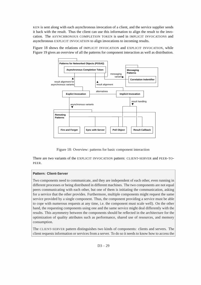
Explict Invocation Implicit Invocation
variant variant variant for eventproducers andconsumers
Client-Server Peer-to-PeerPublish-Subscribe
Broker
realized using
Layers
uses layered architecture
RemotingPatterns
realized using
MessagingPatterns
realized using
Remote Procedure Call Shared RepositoryMessage Queuing
Patterns for ResourceManagement
Lookup
extended by extended by
alternatives
realized using
variant
Figure 19: Overview: patterns for component interaction and distribution
server, that is, it requires an ID or an address of the server and of course the server’s interface.The server responds to the requests of the client, and processes each client request on its own. Itdoes not know about the ID or address of the client before the interaction takes place. Clients areoptimized for their application task, whereas servers are optimized for serving multiple clients.
Both client and server must implement collective tasks, such as security, transaction, and sys-tems management – something that is more complex in aCLIENT-SERVERarchitecture than insimpleEXPLICIT INVOCATIONS.
Sophisticated, distributedCLIENT-SERVERarchitectures usually rely on theBROKER pattern tomake the complexity of the distributed communication manageable. The same is true for thePEER-TO-PEERpattern.
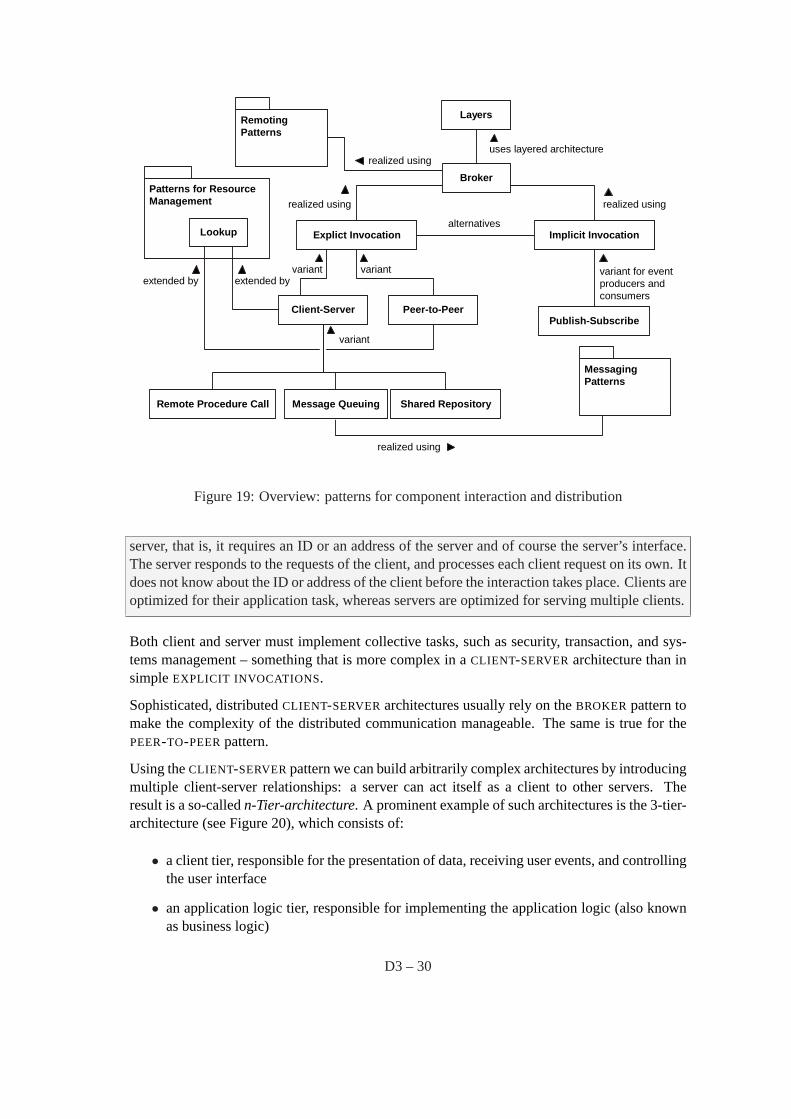
Using theCLIENT-SERVERpattern we can build arbitrarily complex architectures by introducingmultiple client-server relationships: a server can act itself as a client to other servers. Theresult is a so-calledn-Tier-architecture. A prominent example of such architectures is the 3-tier-architecture (see Figure 20), which consists of:
• a client tier, responsible for the presentation of data, receiving user events, and controllingthe user interface
• an application logic tier, responsible for implementing the application logic (also knownas business logic)
D3 – 30
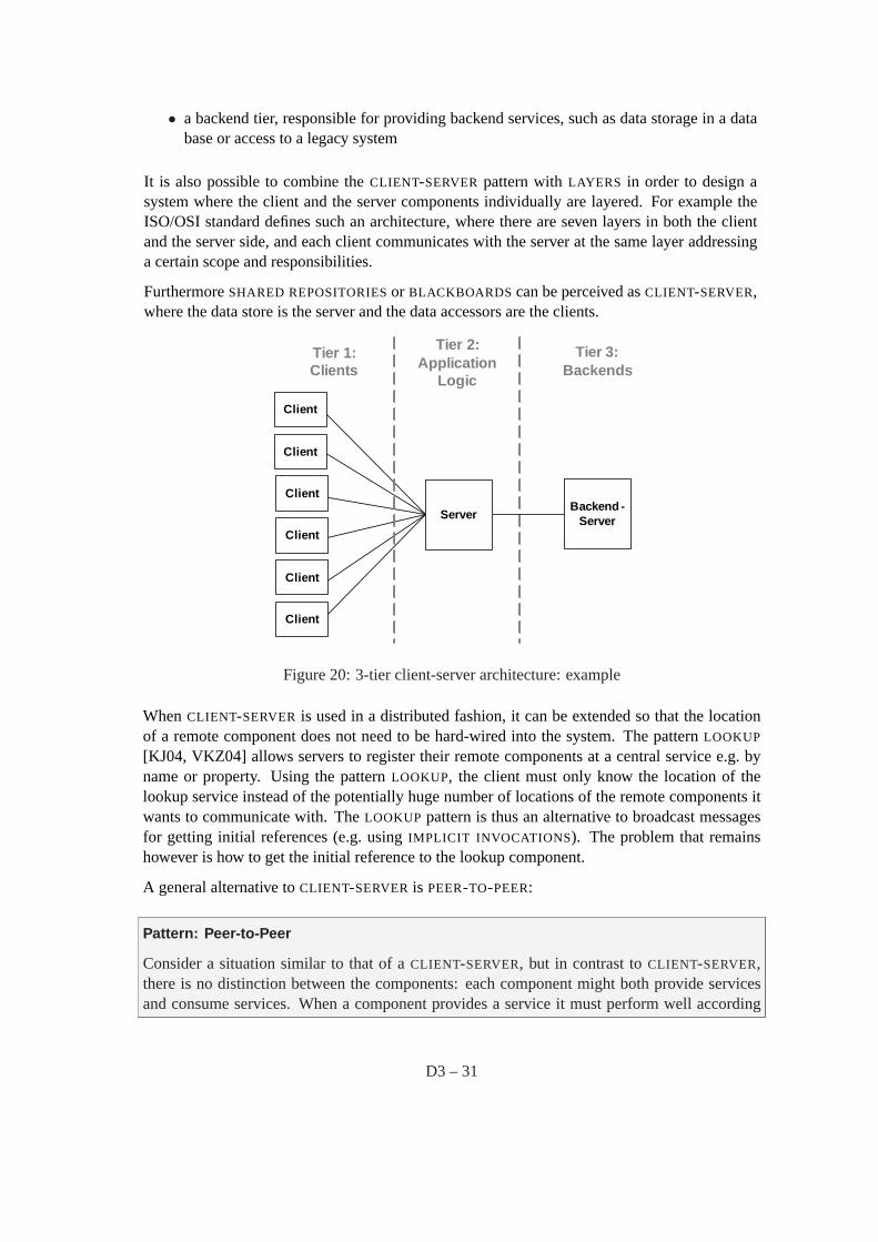
• a backend tier, responsible for providing backend services, such as data storage in a database or access to a legacy system
It is also possible to combine theCLIENT-SERVER pattern withLAYERS in order to design asystem where the client and the server components individually are layered. For example theISO/OSI standard defines such an architecture, where there are seven layers in both the clientand the server side, and each client communicates with the server at the same layer addressinga certain scope and responsibilities.
FurthermoreSHARED REPOSITORIESor BLACKBOARDS can be perceived asCLIENT-SERVER,where the data store is the server and the data accessors are the clients.
Client
Client
Client
Client
Client
Client
Server
Tier 1: Clients
Tier 2:Application
Logic
Tier 3:Backends
Backend -Server
Figure 20: 3-tier client-server architecture: example
WhenCLIENT-SERVER is used in a distributed fashion, it can be extended so that the locationof a remote component does not need to be hard-wired into the system. The patternLOOKUP
[KJ04, VKZ04] allows servers to register their remote components at a central service e.g. byname or property. Using the patternLOOKUP, the client must only know the location of thelookup service instead of the potentially huge number of locations of the remote components itwants to communicate with. TheLOOKUP pattern is thus an alternative to broadcast messagesfor getting initial references (e.g. usingIMPLICIT INVOCATIONS). The problem that remainshowever is how to get the initial reference to the lookup component.
A general alternative toCLIENT-SERVERis PEER-TO-PEER:
Pattern: Peer-to-Peer
Consider a situation similar to that of aCLIENT-SERVER, but in contrast toCLIENT-SERVER,there is no distinction between the components: each component might both provide servicesand consume services. When a component provides a service it must perform well according
D3 – 31
to the demands of the requesting components. Each component must know how to access othercomponents.
In thePEER-TO-PEERpattern each component has equal responsibilities, in particular it may actboth as a client and as a server. Each component offers its own services (or data) and is ableto access the services in other components. ThePEER-TO-PEERnetwork consists of a dynamicnumber of components. APEER-TO-PEERcomponent knows how to access the network. Beforea component can join a network, it must get an initial reference to this network. This is solvedby a bootstrapping mechanism, such as providing public lists of dedicated peers or broadcastmessages (usingIMPLICIT INVOCATION ) in the network announcing peers.
Once an initial reference of thePEER-TO-PEERnetwork is found, we need to find other peers inthe network. For this purpose, each peer (or each dedicated peer) realizes theLOOKUP pattern[KJ04, VKZ04]. UsingLOOKUP peers can be found based on their names or their properties.PEER-TO-PEERcan be realized internally usingCLIENT-SERVER, or other patterns. It usuallyalso uses aBROKER architecture.
WhereasCLIENT-SERVERandPEER-TO-PEERconcentrate onEXPLICIT INVOCATIONS, PUBLISH-SUBSCRIBE4 is an interaction pattern that is heavily based onIMPLICIT INVOCATIONS:
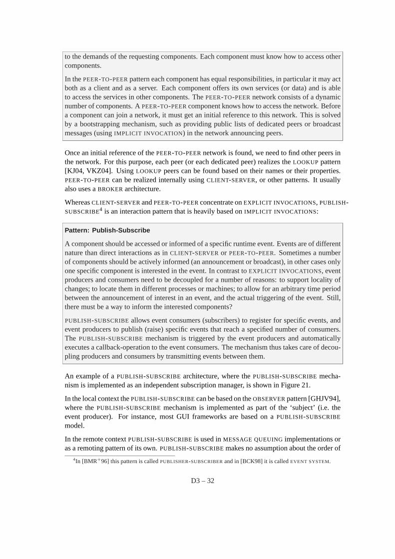
Pattern: Publish-Subscribe
A component should be accessed or informed of a specific runtime event. Events are of differentnature than direct interactions as inCLIENT-SERVERor PEER-TO-PEER. Sometimes a numberof components should be actively informed (an announcement or broadcast), in other cases onlyone specific component is interested in the event. In contrast toEXPLICIT INVOCATIONS, eventproducers and consumers need to be decoupled for a number of reasons: to support locality ofchanges; to locate them in different processes or machines; to allow for an arbitrary time periodbetween the announcement of interest in an event, and the actual triggering of the event. Still,there must be a way to inform the interested components?
PUBLISH-SUBSCRIBEallows event consumers (subscribers) to register for specific events, andevent producers to publish (raise) specific events that reach a specified number of consumers.The PUBLISH-SUBSCRIBE mechanism is triggered by the event producers and automaticallyexecutes a callback-operation to the event consumers. The mechanism thus takes care of decou-pling producers and consumers by transmitting events between them.
An example of aPUBLISH-SUBSCRIBEarchitecture, where thePUBLISH-SUBSCRIBEmecha-nism is implemented as an independent subscription manager, is shown in Figure 21.
In the local context thePUBLISH-SUBSCRIBEcan be based on theOBSERVERpattern [GHJV94],where thePUBLISH-SUBSCRIBE mechanism is implemented as part of the ‘subject’ (i.e. theevent producer). For instance, most GUI frameworks are based on aPUBLISH-SUBSCRIBE
model.
In the remote contextPUBLISH-SUBSCRIBEis used inMESSAGE QUEUINGimplementations oras a remoting pattern of its own.PUBLISH-SUBSCRIBEmakes no assumption about the order of
4In [BMR+96] this pattern is calledPUBLISHER-SUBSCRIBERand in [BCK98] it is calledEVENT SYSTEM.
D3 – 32
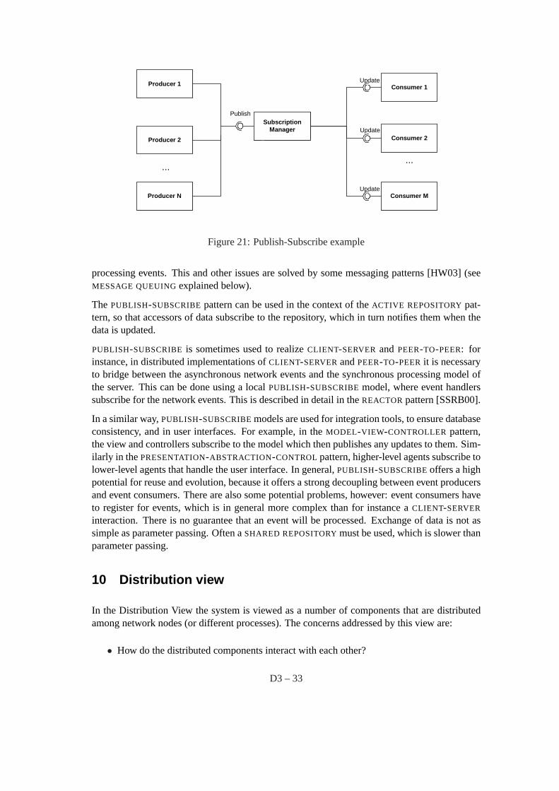
Producer 1 Consumer 1
SubscriptionManager
Update
Publish
Producer N
Producer 2
Consumer M
......
Update
UpdateConsumer 2
Figure 21: Publish-Subscribe example
processing events. This and other issues are solved by some messaging patterns [HW03] (seeMESSAGE QUEUINGexplained below).
The PUBLISH-SUBSCRIBEpattern can be used in the context of theACTIVE REPOSITORYpat-tern, so that accessors of data subscribe to the repository, which in turn notifies them when thedata is updated.
PUBLISH-SUBSCRIBE is sometimes used to realizeCLIENT-SERVER and PEER-TO-PEER: forinstance, in distributed implementations ofCLIENT-SERVERandPEER-TO-PEERit is necessaryto bridge between the asynchronous network events and the synchronous processing model ofthe server. This can be done using a localPUBLISH-SUBSCRIBEmodel, where event handlerssubscribe for the network events. This is described in detail in theREACTORpattern [SSRB00].
In a similar way,PUBLISH-SUBSCRIBEmodels are used for integration tools, to ensure databaseconsistency, and in user interfaces. For example, in theMODEL-VIEW-CONTROLLER pattern,the view and controllers subscribe to the model which then publishes any updates to them. Sim-ilarly in thePRESENTATION-ABSTRACTION-CONTROLpattern, higher-level agents subscribe tolower-level agents that handle the user interface. In general,PUBLISH-SUBSCRIBEoffers a highpotential for reuse and evolution, because it offers a strong decoupling between event producersand event consumers. There are also some potential problems, however: event consumers haveto register for events, which is in general more complex than for instance aCLIENT-SERVER
interaction. There is no guarantee that an event will be processed. Exchange of data is not assimple as parameter passing. Often aSHARED REPOSITORYmust be used, which is slower thanparameter passing.
10 Distribution view
In the Distribution View the system is viewed as a number of components that are distributedamong network nodes (or different processes). The concerns addressed by this view are:
• How do the distributed components interact with each other?
D3 – 33
• How are the distributed components decoupled from each other?
• How are the quality attributes of interoperability, location-transparency, performance, andmodifiability supported?
The components are physically located in different network nodes or processes. They interactwith each other through connectors that pass invocations or data from one to another. The detailsof these interactions can be better explained in the Component Interaction View.
Pattern: Broker
Distributed software system developers face many challenges that do not arise in single-processsoftware. One is the communication across unreliable networks. Others are the integration ofheterogeneous components into coherent applications, as well as the efficient use of networkingresources. If developers of distributed systems must overcome all these challenges within theirapplication code, they may lose their primary focus: to develop applications that efficientlytackle their domain-specific problems.
A BROKER separates the communication functionality of a distributed system from its applica-tion functionality. TheBROKER hides and mediates all communication between the objects orcomponents of a system. ABROKERconsists of a client-sideREQUESTOR[VKZ04] to constructand forward invocations, as well as a server-sideINVOKER [VKZ04] that is responsible for in-voking the operations of the target remote object. AMARSHALLER [VKZ04] on each side ofthe communication path handles the transformation of requests and replies from programming-language native data types into a byte array that can be sent over the transmission medium.
TheBROKER is a compound pattern that is realized using a number of remoting patterns [VKZ04].The most foundational remoting patterns in aBROKER architecture are mentioned above:RE-QUESTOR, INVOKER, and MARSHALLER. There are many others. Some important exam-ples are: aCLIENT PROXY [VKZ04] represents the remote object in the client process. Thisproxy has the same interface as the remote object it represents. AnINTERFACE DESCRIP-TION [VKZ04] is used to make the remote object’s interface known to the clients.LOOKUP
[KJ04, VKZ04] allows clients to discover remote objects.
TheBROKERuses aLAYERS architecture. The layers ofBROKERare also described in [VKZ04].
Many well-knownBROKER realizations are based on theCLIENT SERVER pattern. However,the other patterns for component interactions, such asEXPLICIT INVOCATION, PEER-TO-PEER,MESSAGE QUEUING, andPUBLISH-SUBSCRIBE, can also use aBROKERto isolate communication-related concerns, when used in a distributed setting. Only in very simple distributed systems orin distributed systems with severe constraints (e.g. regarding performance and memory con-sumption), it might be advisable not to use aBROKER.
An example for aBROKER realization is depicted in Figure 22.
TheBROKER can be seen as the general structure that utilizes the patterns from the ComponentInteraction View in a distributed setting. The following remoting patterns [VKZ04] are a num-ber of variants ofCLIENT-SERVER that usually operate in a distributed setting and are mutualalternatives. They usually employ aBROKER architecture internally.
D3 – 34
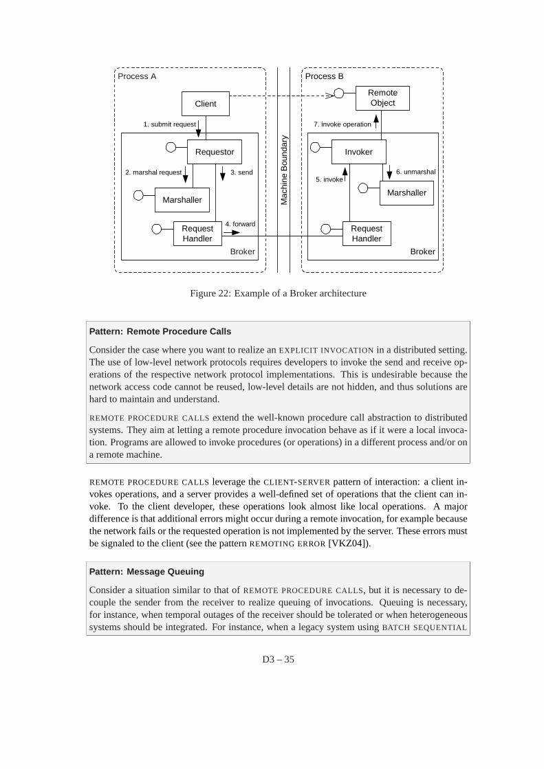
Broker
Process A
Requestor
Mac
hine
Bou
ndar
y
Process B
Broker
ClientRemoteObject
Invoker
RequestHandler
MarshallerMarshaller
RequestHandler
1. submit request
2. marshal request 3. send
4. forward
5. invoke6. unmarshal
7. invoke operation
Figure 22: Example of a Broker architecture
Pattern: Remote Procedure Calls
Consider the case where you want to realize anEXPLICIT INVOCATION in a distributed setting.The use of low-level network protocols requires developers to invoke the send and receive op-erations of the respective network protocol implementations. This is undesirable because thenetwork access code cannot be reused, low-level details are not hidden, and thus solutions arehard to maintain and understand.
REMOTE PROCEDURE CALLSextend the well-known procedure call abstraction to distributedsystems. They aim at letting a remote procedure invocation behave as if it were a local invoca-tion. Programs are allowed to invoke procedures (or operations) in a different process and/or ona remote machine.
REMOTE PROCEDURE CALLSleverage theCLIENT-SERVERpattern of interaction: a client in-vokes operations, and a server provides a well-defined set of operations that the client can in-voke. To the client developer, these operations look almost like local operations. A majordifference is that additional errors might occur during a remote invocation, for example becausethe network fails or the requested operation is not implemented by the server. These errors mustbe signaled to the client (see the patternREMOTING ERROR[VKZ04]).
Pattern: Message Queuing
Consider a situation similar to that ofREMOTE PROCEDURE CALLS, but it is necessary to de-couple the sender from the receiver to realize queuing of invocations. Queuing is necessary,for instance, when temporal outages of the receiver should be tolerated or when heterogeneoussystems should be integrated. For instance, when a legacy system usingBATCH SEQUENTIAL
D3 – 35
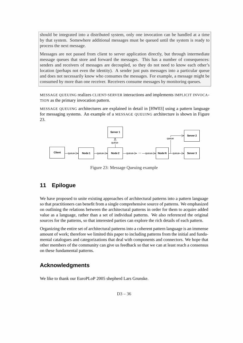
should be integrated into a distributed system, only one invocation can be handled at a timeby that system. Somewhere additional messages must be queued until the system is ready toprocess the next message.
Messages are not passed from client to server application directly, but through intermediatemessage queues that store and forward the messages. This has a number of consequences:senders and receivers of messages are decoupled, so they do not need to know each other’slocation (perhaps not even the identity). A sender just puts messages into a particular queueand does not necessarily know who consumes the messages. For example, a message might beconsumed by more than one receiver. Receivers consume messages by monitoring queues.
MESSAGE QUEUINGrealizesCLIENT-SERVERinteractions and implementsIMPLICIT INVOCA -TION as the primary invocation pattern.
MESSAGE QUEUINGarchitectures are explained in detail in [HW03] using a pattern languagefor messaging systems. An example of aMESSAGE QUEUINGarchitecture is shown in Figure23.
Node 1queue Node 2queue queue Node Nqueue... queueClient Server 3
Server 1Server 2
queue
queue
Figure 23: Message Queuing example
11 Epilogue
We have proposed to unite existing approaches of architectural patterns into a pattern languageso that practitioners can benefit from a single comprehensive source of patterns. We emphasizedon outlining the relations between the architectural patterns in order for them to acquire addedvalue as a language, rather than a set of individual patterns. We also referenced the originalsources for the patterns, so that interested parties can explore the rich details of each pattern.
Organizing the entire set of architectural patterns into a coherent pattern language is an immenseamount of work; therefore we limited this paper to including patterns from the initial and funda-mental catalogues and categorizations that deal with components and connectors. We hope thatother members of the community can give us feedback so that we can at least reach a consensuson these fundamental patterns.
Acknowledgments
We like to thank our EuroPLoP 2005 shepherd Lars Grunske.
D3 – 36
References
[AIS+77] C. Alexander, S. Ishikawa, M. Silverstein, M. Jakobson, I. Fiksdahl-King, andS. Angel.A Pattern Language – Towns, Buildings, Construction. Oxford Univ.Press, 1977.
[Ale79] C. Alexander.The Timeless Way of Building. Oxford Univ. Press, 1979.
[BCK98] L. Bass, P. Clements, and R. Kazman.Software Architecture in Practice.Addison-Wesley Longman, Reading, MA, 1998.
[BH03] Frank Buschmann and Kevlin Henney. Explicit interface and object manager.In Proceedings of 8th European Conference on Pattern Languages of Programs(EuroPlop 2003), Irsee, Germany, July 2003.
[BMR+96] F. Buschmann, R. Meunier, H. Rohnert, P. Sommerlad, and M. Stal.Pattern-orinented Software Architecture - A System of Patterns. J. Wiley and Sons Ltd.,1996.
[CBB+02] Paul Clements, Felix Bachmann, Len Bass, David Garlan, James Ivers, ReedLittle, Robert Nord, and Judith Stafford.Documenting Software Architectures:Views and Beyond. Addison-Wesley, 2002.
[Cop96] J. Coplien.Software Patterns Management Briefing. SIGS, 1996.
[Cou87] J. Coutaz. PAC, an Object Oriented Model for Dialog Design. InProceedingsInteract’87, Stuttgart, pages 431–436. IEEE Computer Society, 1987.
[GCCC85] D. Gelernter, N. Carriero, S. Chandran, and S. Chang. Parallel programmingin linda. InProceedings of the 1985 International Conference on Parallel Pro-cessing, pages 255–263,, 1985.
[GHJV94] E. Gamma, R. Helm, R. Johnson, and J. Vlissides.Design Patterns: Elementsof Reusable Object-Oriented Software. Addison-Wesley, 1994.
[GMSM00] J. Garcia-Martin and M. Sutil-Martin. Virtual machines and abstract compilers- towards a compiler pattern language. InProceedings of EuroPlop 2000, pages375–396, Irsee, Germany, July 2000.
[HNS00] Christine Hofmeister, Robert Nord, and Dilip Soni.Applied software architec-ture. Addison-Wesley Longman Publishing Co., Inc., 2000.
[HW03] G. Hohpe and B. Woolf.Enterprise Integration Patterns. Addison-Wesley,2003.
[IEE00] IEEE. Recommended Practice for Architectural Description of Software Inten-sive Systems. Technical Report IEEE-std-1471-2000, IEEE, 2000.
[KJ04] M. Kircher and P. Jain.Pattern-Oriented Software Architecture, Volume 3:Patterns for Resource Management. J. Wiley and Sons Ltd., 2004.
D3 – 37

[KP88] Glenn E. Krasner and Stephen T. Pope. A cookbook for using the model-viewcontroller user interface paradigm in smalltalk-80.J. Object Oriented Pro-gram., 1(3):26–49, 1988.
[Kru95] Philippe Kruchten. The 4+1 view model of architecture.IEEE Softw., 12(6):42–50, 1995.
[MM03] N. R. Mehta and N. Medvidovic. Composing architectural styles from archi-tectural primitives. InProceedings of the 9th European software engineeringconference held jointly with 10th ACM SIGSOFT international symposium onFoundations of software engineering, pages 347–350, Helsinki, Finland, 2003.ACM Press.
[MT00] Nenad Medvidovic and Richard N. Taylor. A Classification and ComparisonFramework for Software Architecture Description Languages.IEEE Trans.Softw. Eng., 26(1):70–93, 2000.
[PW92] Dewayne E. Perry and Alexander L. Wolf. Foundations for the study of softwarearchitecture.ACM SIGSOFT Software Engineering Notes, 17(4), October 1992.
[SC97] Mary Shaw and Paul C. Clements. A field guide to boxology: Preliminary clas-sification of architectural styles for software systems. InCOMPSAC ’97: Pro-ceedings of the 21st International Computer Software and Applications Con-ference, pages 6–13. IEEE Computer Society, 1997.
[SG96] M. Shaw and D. Garlan.Software Architecture: Perspectives on an EmergingDiscipline. Addison-Wesley, 1996.
[Sha96] Mary Shaw. Some Patterns for Software Architechture. In John Vlissides,James Coplien, and Norman Kerth, editors,Pattern Languages of Program De-sign, Vol 2, pages 255–269. Reading, MA: Addison-Wesley, 1996.
[SSRB00] D. C. Schmidt, M. Stal, H. Rohnert, and F. Buschmann.Patterns for Concurrentand Distributed Objects. Pattern-Oriented Software Architecture. J. Wiley andSons Ltd., 2000.
[TMA +96] Richard N. Taylor, Nenad Medvidovic, Kenneth M. Anderson, Jr.E. James Whitehead, Jason E. Robbins, Kari A. Nies, Peyman Oreizy, and Deb-orah L. Dubrow. A component- and message-based architectural style for guisoftware.IEEE Trans. Softw. Eng., 22(6):390–406, 1996.
[VKZ04] M. Voelter, M. Kircher, and U. Zdun.Remoting Patterns. Pattern Series. JohnWiley and Sons, 2004.
[Zac87] John A. Zachman. A framework for information systems architecture.IBMSyst. J., 26(3):276–292, 1987.
[Zdu03] U. Zdun. Patterns of tracing software structures and dependencies. InProceed-ings of EuroPlop 2003, Irsee, Germany, June 2003.
D3 – 38

[Zdu04] U. Zdun. Pattern language for the design of aspect languages and aspect com-position frameworks.IEE Proceedings Software, 151(2):67–83, April 2004.
D3 – 39