management component transport protocol (mctp) smbus/i2c ... · dsp0237 mctp smbus/i2c transport...
TRANSCRIPT
1
Document Number: DSP0237 2
Date: 2017-05-21 3
Version: 1.1.0 4
Management Component Transport Protocol 5
(MCTP) SMBus/I2C Transport Binding 6
Specification 7
Supersedes: 1.0.0 8
Document Class: Normative 9
Document Status: Published 10
Document Language: en-US 11
MCTP SMBus/I2C Transport Binding Specification DSP0237
2 Published Version 1.1.0
12
Copyright Notice 13
Copyright © 2017 Distributed Management Task Force, Inc. (DMTF). All rights reserved. 14
DMTF is a not-for-profit association of industry members dedicated to promoting enterprise and systems 15 management and interoperability. Members and non-members may reproduce DMTF specifications and 16 documents, provided that correct attribution is given. As DMTF specifications may be revised from time to 17 time, the particular version and release date should always be noted. 18
Implementation of certain elements of this standard or proposed standard may be subject to third party 19 patent rights, including provisional patent rights (herein "patent rights"). DMTF makes no representations 20 to users of the standard as to the existence of such rights, and is not responsible to recognize, disclose, 21 or identify any or all such third party patent right, owners or claimants, nor for any incomplete or 22 inaccurate identification or disclosure of such rights, owners or claimants. DMTF shall have no liability to 23 any party, in any manner or circumstance, under any legal theory whatsoever, for failure to recognize, 24 disclose, or identify any such third party patent rights, or for such party’s reliance on the standard or 25 incorporation thereof in its product, protocols or testing procedures. DMTF shall have no liability to any 26 party implementing such standard, whether such implementation is foreseeable or not, nor to any patent 27 owner or claimant, and shall have no liability or responsibility for costs or losses incurred if a standard is 28 withdrawn or modified after publication, and shall be indemnified and held harmless by any party 29 implementing the standard from any and all claims of infringement by a patent owner for such 30 implementations. 31
For information about patents held by third-parties which have notified the DMTF that, in their opinion, 32 such patent may relate to or impact implementations of DMTF standards, visit 33 http://www.dmtf.org/about/policies/disclosures.php. 34
PCI-SIG, PCIe, and the PCI HOT PLUG design mark are registered trademarks or service marks of PCI-35 SIG. 36
All other marks and brands are the property of their respective owners. 37
38
DSP0237 MCTP SMBus/I2C Transport Binding Specification
Version 1.1.0 Published 3
CONTENTS 39
Foreword ....................................................................................................................................................... 5 40
Introduction.................................................................................................................................................... 6 41
1 Scope .................................................................................................................................................... 7 42
2 Normative references ............................................................................................................................ 7 43
3 Terms and definitions ............................................................................................................................ 7 44
4 Symbols and abbreviated terms ............................................................................................................ 8 45
5 Conventions ........................................................................................................................................ 10 46 5.1 Reserved and unassigned values ............................................................................................. 10 47 5.2 Byte ordering ............................................................................................................................. 11 48
6 MCTP over SMBus/I2C transport ........................................................................................................ 11 49
6.1 Terminology .............................................................................................................................. 11 50 6.2 Transport binding use with I
2C .................................................................................................. 12 51
6.3 MCTP packet encapsulation ..................................................................................................... 12 52 6.4 Bridges and packet formatting .................................................................................................. 13 53 6.5 MCTP support discovery........................................................................................................... 13 54 6.6 Support for fixed-address devices ............................................................................................ 14 55 6.7 Supported media ....................................................................................................................... 14 56 6.8 Physical address format for MCTP control messages .............................................................. 15 57 6.9 Get endpoint ID Medium-Specific Information .......................................................................... 15 58 6.10 Bus owner address ................................................................................................................... 15 59 6.11 Bus address assignment .......................................................................................................... 15 60 6.12 SMBus/I
2C considerations for MCTP messages ...................................................................... 19 61
6.13 Fairness arbitration ................................................................................................................... 20 62 6.14 NACK window ........................................................................................................................... 21 63 6.15 Fairness arbitration requirements for MCTP bridges ................................................................ 22 64 6.16 Fairness arbitration requirements for non-bridge endpoints ..................................................... 23 65 6.17 Fairness arbitration timing ........................................................................................................ 24 66 6.18 MCTP packet timing requirements ........................................................................................... 25 67 6.19 MCTP control message timing requirements............................................................................ 27 68 6.20 "Stuck 0" condition handling ..................................................................................................... 28 69 6.21 MCTP over SMBus/I
2C protocol anti-aliasing ........................................................................... 29 70
6.22 Well-known and reserved slave addresses .............................................................................. 30 71 6.23 Fixed address allocation ........................................................................................................... 31 72 6.24 Recommended address range allocation for computer systems ............................................. 32 73
ANNEX A (informative) Notation ............................................................................................................... 35 74
ANNEX B (informative) Change log .......................................................................................................... 36 75
76
Figures 77
Figure 1 – MCTP over SMBus/I2C packet format ....................................................................................... 12 78
Figure 2 – Address assignment flow ........................................................................................................... 18 79
Figure 3 – Allowed byte range for first NACK'd byte ................................................................................... 21 80
Figure 4 – Fairness arbitration timing measurement for SMBus and I2C ................................................... 24 81
Figure 5 – Example system configuration ................................................................................................... 32 82
83
MCTP SMBus/I2C Transport Binding Specification DSP0237
4 Published Version 1.1.0
Tables 84
Table 1 – Packet header field descriptions ................................................................................................. 12 85
Table 2 – Supported media ......................................................................................................................... 15 86
Table 3 – Physical address format .............................................................................................................. 15 87
Table 4 – Medium-Specific Information ...................................................................................................... 15 88
Table 5 – Fairness arbitration timing values for 100 kHz SMBus/I2C ......................................................... 24 89
Table 6 – Fairness arbitration timing values for 400 kHz I2C ...................................................................... 25 90
Table 7 – Fairness arbitration timing values for 1MHz I2C.......................................................................... 25 91
Table 8 – Timing specifications for MCTP packets on SMBus/I2C ............................................................. 26 92
Table 9 – Timing Specifications for MCTP control messages on SMBus .................................................. 27 93
Table 10 – Well-known and reserved slave addresses .............................................................................. 30 94
Table 11 – Slave address allocation for computer systems ....................................................................... 33 95
96

DSP0237 MCTP SMBus/I2C Transport Binding Specification
Version 1.1.0 Published 5
Foreword 97
The Management Component Transport Protocol (MCTP) SMBus/I2C Transport Binding Specification 98 (DSP0237) was prepared by the PMCI Subgroup of the Pre-OS Working Group. 99
DMTF is a not-for-profit association of industry members dedicated to promoting enterprise and systems 100 management and interoperability. 101
Acknowledgments 102
The DMTF acknowledges the following individuals for their contributions to this document: 103
Editor: 104
Yuval Itkin – Mellanox Technologies 105
Contributors: 106
Alan Berenbaum – SMSC 107
Klodnicki Edward - IBM 108
Kozlowski Koe – Dell Inc 109
Patrick Caporale – Lenovo 110
Patrick Schoeller – Hewlett Packard Enterprise 111
Phil Chidester – Dell Inc 112
John Leung - Intel Corporation 113
Eliel Louzoun – Intel Corporation 114
Hemal Shah - Broadcom Limited 115
Tom Slaight – Intel Corporation 116
Yi Zeng – Intel Corporation 117
118

MCTP SMBus/I2C Transport Binding Specification DSP0237
6 Published Version 1.1.0
Introduction 119
The Management Component Transport Protocol (MCTP) over SMBus/I2C transport binding defines a 120 transport binding for facilitating communication between platform management subsystem components 121 (e.g., management controllers, managed devices) over SMBus/I2C. 122
The MCTP Base Specification (MCTP) describes the protocol and commands used for communication 123 within and initialization of an MCTP network. The MCTP over SMBus/I2C transport binding definition in 124 this specification includes a packet format, physical address format, message routing, and discovery 125 mechanisms for MCTP over SMBus/I2C communications. 126
127
DSP0237 MCTP SMBus/I2C Transport Binding Specification
Version 1.1.0 Published 7
Management Component Transport Protocol (MCTP) 128
SMBus/I2C Transport Binding Specification 129
1 Scope 130
This document provides the specifications for the Management Component Transport Protocol (MCTP) 131 transport binding for SMBus/I
2C. 132
2 Normative references 133
The following referenced documents are indispensable for the application of this document. For dated or 134 versioned references, only the edition cited (including any corrigenda or DMTF update versions) applies. 135 For references without a date or version, the latest published edition of the referenced document 136 (including any corrigenda or DMTF update versions) applies. 137
DMTF DSP0136, Alert Standard Format Specification 2.0, 138 http://www.dmtf.org/standards/documents/ASF/DSP0136.pdf 139
DMTF, DSP0236, Management Component Transport Protocol (MCTP) Base Specification 1.3, MCTP, 140 http://www.dmtf.org/sites/default/files/standards/documents/DSP0236_1.3.0.pdf 141
DMTF, DSP0239, Management Component Transport Protocol (MCTP) IDs and Codes 1.4, MCTP_ID, 142 http://www.dmtf.org/sites/default/files/standards/documents/DSP0239_1.4.0.pdf 143
IPMI Consortium, Intelligent Platform Management Interface Specification, Second Generation 2.0, 2006, 144 ftp://download.intel.com/design/servers/ipmi/IPMIv2_0rev1_0.pdf 145
ISO/IEC Directives, Part 2, Rules for the structure and drafting of International Standards, 146 http://isotc.iso.org/livelink/livelink?func=ll&objId=4230456&objAction=browse&sort=subtype 147
NXP Semiconductors, I2C-bus specification and user manual, 4 April 2014 148
http://www.nxp.com/documents/user_manual/UM10204.pdf 149
SBS Implementers Forum, System Management Bus (SMBus) Specification v2.0, SMBus, August 2000, 150 http://www.smbus.org/specs/smbus20.pdf 151
3 Terms and definitions 152
In this document, some terms have a specific meaning beyond the normal English meaning. Those terms 153 are defined in this clause. 154
The terms "shall" ("required"), "shall not", "should" ("recommended"), "should not" ("not recommended"), 155 "may", "need not" ("not required"), "can" and "cannot" in this document are to be interpreted as described 156 in ISO/IEC Directives, Part 2, Annex H. The terms in parentheses are alternatives for the preceding term, 157 for use in exceptional cases when the preceding term cannot be used for linguistic reasons. Note that 158 ISO/IEC Directives, Part 2, Annex H specifies additional alternatives. Occurrences of such additional 159 alternatives shall be interpreted in their normal English meaning. 160
The terms "clause", "subclause", "paragraph", and "annex" in this document are to be interpreted as 161 described in ISO/IEC Directives, Part 2, Clause 5. 162
MCTP SMBus/I2C Transport Binding Specification DSP0237
8 Published Version 1.1.0
The terms "normative" and "informative" in this document are to be interpreted as described in ISO/IEC 163 Directives, Part 2, Clause 3. In this document, clauses, subclauses, or annexes labeled "(informative)" do 164 not contain normative content. Notes and examples are always informative elements. 165
The terms defined in DSP0004, DSP0223, and DSP1001 apply to this document. The following additional 166 terms are used in this document. 167
3.1168
Address Resolution Protocol 169
ARP 170
refers to the procedure used to dynamically determine the addresses of devices on a shared 171 communication medium 172
4 Symbols and abbreviated terms 173
The following symbols and abbreviations are used in this document. 174
4.1175
ACK 176
acknowledge 177
4.2178
ARP 179
Address Resolution Protocol 180
4.3181
ASF 182
Alert Standard Format 183
4.4184
BMC 185
baseboard management controller 186
4.5187
EEPROM 188
Electrically Erasable Programmable Read-Only Memory 189
4.6190
EID 191
endpoint identifier 192
4.7193
I2C 194
Inter-Integrated Circuit 195
4.8196
I/O 197
input/output 198
4.9199
IPMB 200
Intelligent Platform Management Bus 201
DSP0237 MCTP SMBus/I2C Transport Binding Specification
Version 1.1.0 Published 9
4.10202
IPMI 203
Intelligent Platform Management Interface 204
4.11205
kHz 206
kilohertz 207
4.12208
LSb 209
least significant bit 210
4.13211
LSB 212
least significant byte 213
4.14214
max 215
maximum 216
4.15217
MCTP 218
Management Component Transport Protocol 219
4.16220
min 221
minimum 222
4.17223
ms 224
millisecond 225
4.18226
MSB 227
most significant byte 228
4.19229
MTU 230
Maximum Transmission Unit 231
4.20232
NACK 233
not acknowledge 234
4.21235
PCI 236
peripheral component interconnect 237
4.22238
PCIe® 239
PCI Express™ 240
MCTP SMBus/I2C Transport Binding Specification DSP0237
10 Published Version 1.1.0
4.23241
PEC 242
packet error code 243
4.24244
PMCI 245
Platform Management Component Intercommunications 246
4.25247
PSA 248
persistent slave address 249
4.26250
rsvd 251
reserved (not case sensitive) 252
4.27253
SCL 254
serial clock 255
4.28256
SDA 257
serial data 258
4.29259
sec 260
second 261
4.30262
SEEPROM 263
serial EEPROM 264
4.31265
SMBus 266
System Management Bus 267
4.32268
UDID 269
unique device identifier 270
5 Conventions 271
The conventions described in the following clauses apply to this specification. 272
5.1 Reserved and unassigned values 273
Unless otherwise specified, any reserved, unspecified, or unassigned values in enumerations or other 274 numeric ranges are reserved for future definition by the DMTF. 275
Unless otherwise specified, numeric or bit fields that are designated as reserved shall be written as 0 276 (zero) and ignored when read. 277
DSP0237 MCTP SMBus/I2C Transport Binding Specification
Version 1.1.0 Published 11
5.2 Byte ordering 278
Unless otherwise specified, byte ordering of multi-byte numeric fields or bit fields is "Big Endian" (that is, 279 the lower byte offset holds the most significant byte, and higher offsets hold lesser significant bytes). 280
6 MCTP over SMBus/I2C transport 281
The MCTP over SMBus/I2C transport binding defines how MCTP packets are delivered over a physical 282
SMBus or I2C medium using SMBus transactions. This includes how physical addresses are used, how 283
fixed addresses are accommodated, how physical address assignment is accomplished for hot-plug or 284 other devices that require dynamic physical address assignment, and how MCTP support is discovered. 285 Timing specifications for bus and MCTP control operations are also given, and a "fairness" protocol is 286 defined for the purpose of avoiding deadlock and starvation/lockout situations among MCTP endpoints. 287
The binding has been designed to be able to share the same bus as devices communicating using earlier 288 SMBus/I
2C management protocols such as Alert Standard Format (ASF) and IPMI, and with vendor-289
specific devices using SMBus/I2C protocols. The specifications can also allow a given device to 290
incorporate non-MCTP SMBus functions alongside MCTP. This is described in more detail in 6.21. 291
6.1 Terminology 292
According to SMBus, SMBus devices are categorized as follows, where Address Resolution Protocol 293 (ARP) refers to the SMBus Address Resolution Protocol (a dynamic slave address assignment protocol) 294 and UDID refers to a "unique device identifier", a 128-bit value that a device uses during the ARP process 295 to uniquely identify itself. Because these protocols are implemented with command transactions that are 296 run on top of the SMBus physical specification, it is possible to use these protocols on devices that 297 support an I
2C physical interface. 298
ARP-capable 299
SMBus term indicating a device that supports all SMBus ARP commands with the exception of 300 the optional Host Notify command. The slave address is assignable. The device supports both 301 Reset commands. 302
Fixed and Discoverable 303
SMBus term indicating a device supports the Prepare to ARP, directed Get UDID, general Get 304 UDID, and Assign Address commands. The slave address is fixed; the device will accept the 305 Assign Address command but will not allow address reassignment. The device supports both 306 Reset commands. 307
Fixed - Not Discoverable 308
SMBus term indicating a device supports the directed Get UDID command. The slave address 309 is fixed. 310
Non-ARP-capable 311
SMBus term indicating a device does not support any ARP commands. The slave address is 312 fixed. 313
Fixed Address 314
For this specification, this term is be used to refer to any device that uses a fixed slave address, 315 without distinguishing whether it is "Fixed and Discoverable", "Fixed, not Discoverable", or 316 "Non-ARP-capable". 317
MCTP SMBus/I2C Transport Binding Specification DSP0237
12 Published Version 1.1.0
6.2 Transport binding use with I2C 318
The transport binding defined in this specification has also been designed to be able to work with 319 standard-mode fast-mode (400 kHz) and Fast-mode Plus (1MHz) I
2C buses that use 7-bit addressing; 10-320
bit addressing is not supported. This binding has not been specified for use with high-speed I2C 321
specifications. 322
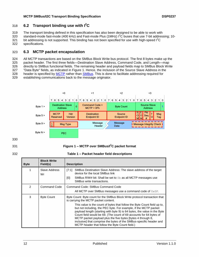
6.3 MCTP packet encapsulation 323
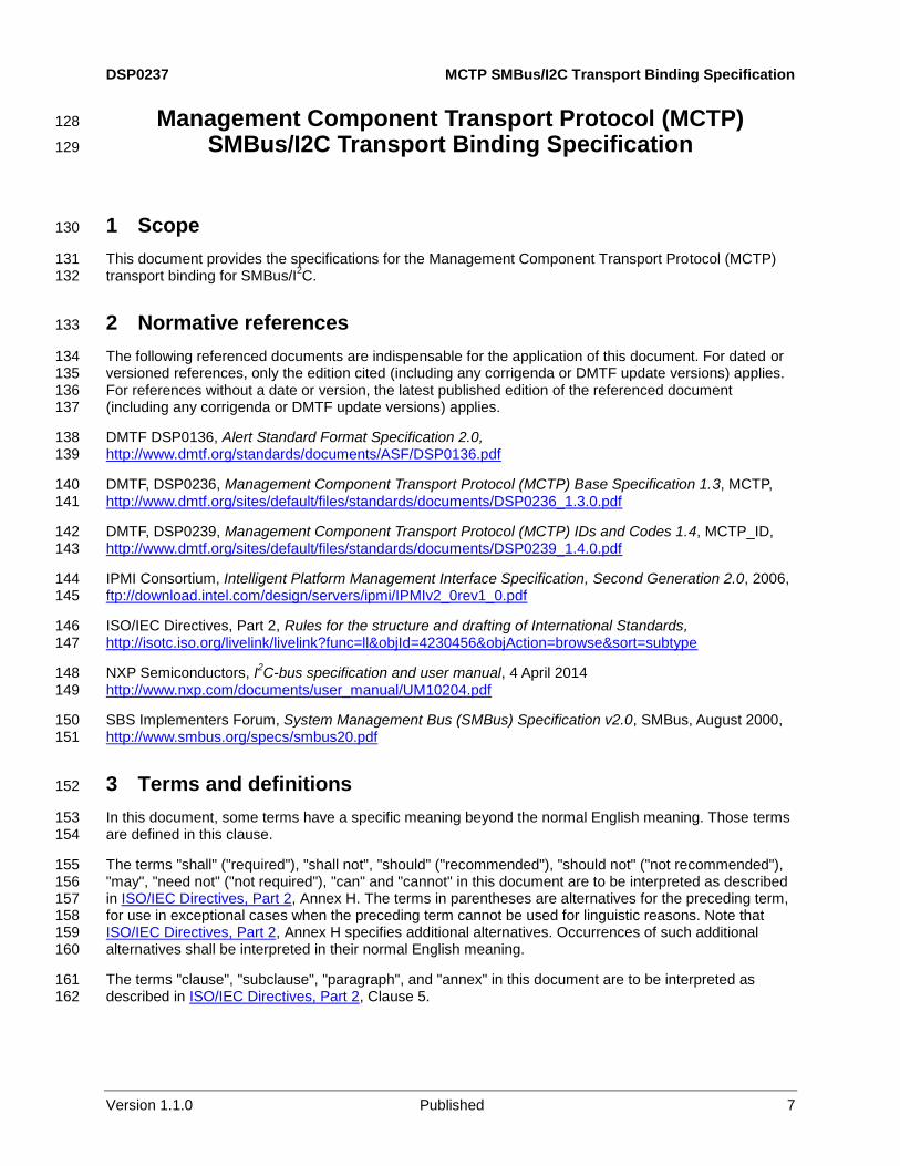
All MCTP transactions are based on the SMBus Block Write bus protocol. The first 8 bytes make up the 324 packet header. The first three fields—Destination Slave Address, Command Code, and Length—map 325 directly to SMBus functional fields. The remaining header and payload fields map to SMBus Block Write 326 "Data Byte" fields, as indicated in Figure 1. Hence, the inclusion of the Source Slave Address in the 327 header is specified by MCTP rather than SMBus. This is done to facilitate addressing required for 328 establishing communications back to the message originator. 329
7
+0
6 5 4 3 2 1 0 7 6 5 4 3 2 1 0 7 6 5 4 3 2 1 0 7 6 5 4 3 2 1 0
+1 +2 +3
Command Code =
MCTP = 0FhByte Count0
Destination Slave
Address
Source Slave
Address1Byte 1 >
Byte 5 >
Byte 9 >
Byte N >
Message
Header
Message
Data
PEC
Source
Endpoint ID
Destination
Endpoint ID
S
O
M
E
O
M
T
O
Msg
Tag
Pkt
Seq
#
Msg Type
MCTP
Reserved
Hdr
Version
IC
Message Integrity Check
330
Figure 1 – MCTP over SMBus/I2C packet format 331
Table 1 – Packet header field descriptions 332
Byte Block Write Field(s) Description
1 Slave Address
Wr
[7:1] SMBus Destination Slave Address: The slave address of the target device for the local SMBus link
[0]: SMBus R/W# bit: Shall be set to 0b as all MCTP messages use
SMBus write transactions.
2 Command Code Command Code: SMBus Command Code
All MCTP over SMBus messages use a command code of 0x0F.
3 Byte Count Byte Count: Byte count for the SMBus Block Write protocol transaction that is carrying the MCTP packet content.
This value is the count of bytes that follow the Byte Count field up to, but not including, the PEC byte. For example, if the MCTP packet payload length (starting with byte 9) is 64 bytes, the value in the Byte Count field would be 69. (The count of 69 accounts for 64 bytes of MCTP packet payload plus the five bytes [bytes 4 through 8, inclusive] that comprise the bytes of the SMBus-specific header and MCTP header that follow the Byte Count field.)
DSP0237 MCTP SMBus/I2C Transport Binding Specification
Version 1.1.0 Published 13
Byte Block Write Field(s) Description
4 Data Byte 1 SMBus Source Slave address
[7:1] : For the local SMBus link, the slave address of the source device.
[0]: This bit shall be set to 1b. The value enables MCTP to be
differentiated from IPMI over SMBus and IPMB (IPMI over I2C)
protocols.
5 Data Byte 2 [7:4] MCTP reserved: This nibble is reserved for definition by the MCTP Base Specification.
[3:0] MCTP header version:
Set to 0001b for MCTP devices that are conformant to the MCTP Base Specification 1.0 and this version of the SMBus transport binding.
All other values = Reserved.
6 Data Byte 3 Destination endpoint ID (*)
7 Data Byte 4 Source endpoint ID (*)
8 Data Byte 5 [7] SOM: Start Of Message flag (*)
[6] EOM: End Of Message flag (*)
[5:4] Packet sequence number (*)
[3] Tag Owner (TO) bit (*)
[2:0] Message tag (*)
9 Data Byte 6 [7] IC: Integrity Check bit (*)
[6:0] Message type (*)
10:N-1 Data Bytes 7:M Message header and data (*)
N PEC Packet error code (PEC): The PEC as defined in the SMBus 2.0 Specification. All MCTP transactions shall include a PEC byte. The PEC
byte shall be transmitted by the source and checked by the destination.
(*) Indicates a field that is defined by the MCTP Base Specification.
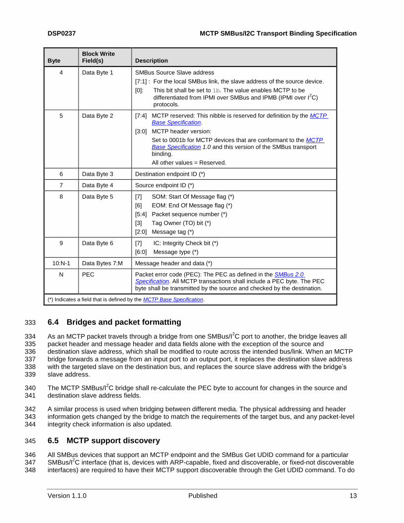
6.4 Bridges and packet formatting 333
As an MCTP packet travels through a bridge from one SMBus/I2C port to another, the bridge leaves all 334
packet header and message header and data fields alone with the exception of the source and 335 destination slave address, which shall be modified to route across the intended bus/link. When an MCTP 336 bridge forwards a message from an input port to an output port, it replaces the destination slave address 337 with the targeted slave on the destination bus, and replaces the source slave address with the bridge’s 338 slave address. 339
The MCTP SMBus/I2C bridge shall re-calculate the PEC byte to account for changes in the source and 340
destination slave address fields. 341
A similar process is used when bridging between different media. The physical addressing and header 342 information gets changed by the bridge to match the requirements of the target bus, and any packet-level 343 integrity check information is also updated. 344
6.5 MCTP support discovery 345
All SMBus devices that support an MCTP endpoint and the SMBus Get UDID command for a particular 346 SMBus/I
2C interface (that is, devices with ARP-capable, fixed and discoverable, or fixed-not discoverable 347
interfaces) are required to have their MCTP support discoverable through the Get UDID command. To do 348
MCTP SMBus/I2C Transport Binding Specification DSP0237
14 Published Version 1.1.0
this, endpoints shall return a value of 1b in bit 5 (the ASF bit) in the Interface field in the Get UDID 349
command. 350
Once support for ASF has been indicated, an MCTP control message (for example, Get MCTP Version 351 Support) can be issued to the device to determine whether it supports MCTP. The SMBus command byte 352 for MCTP packets uses a value that has been allocated by the DMTF for MCTP use and does not overlap 353 values used for ASF. This enables older devices that indicate ASF support to be queried for MCTP 354 support without conflict. This is described in more detail in 6.6. Devices that do not support the Get UDID 355 command will need to have their support for MCTP configured into the bus owner as described in 6.6. 356
I2C devices can also support the SMBus protocols and commands for being an ARP-able device that is 357
also discoverable as an MCTP device. This is required for hot-plug I2C devices using MCTP. 358
6.6 Support for fixed-address devices 359
MCTP bus owners shall include non-volatile options to record the addresses used by fixed-address 360 devices on SMBus/I
2C buses that they own, and which of those devices support MCTP. 361
For non-MCTP devices, the MCTP bus owner needs this information to know which fixed addresses to 362 avoid when performing SMBus ARP for the bus. (Alternatively, the bus owner could be configured with a 363 range of SMBus slave addresses that the bus owner is allowed to allocate from.) 364
For MCTP devices, the bus owner needs this information to perform EID assignment and, if the bus 365 owner is also an MCTP bridge, routing table initialization and operation. 366
For fixed-address MCTP devices that do not support the Get UDID command (that is, non-ARP-capable 367 devices), the bus owner needs to also be configured with information that identifies the device as 368 supporting MCTP. 369
For fixed-address devices that support the SMBus Get UDID command (that is, devices with ARP-370 capable, Fixed and Discoverable, or Fixed-Not Discoverable SMBus interfaces) the bus owner can either 371 discover whether the device supports MCTP by using the discovery approach described in 6.5, or it could 372 have this information configured at the same time that the slave address information for the fixed-address 373 device is provided. 374
It is recommended that general-purpose devices that act as MCTP bus owners allow being configured to 375 support at least 16 different fixed-address devices for each SMBus/I
2C bus they own. This number would 376
include both MCTP and non-MCTP devices. 377
6.7 Supported media 378
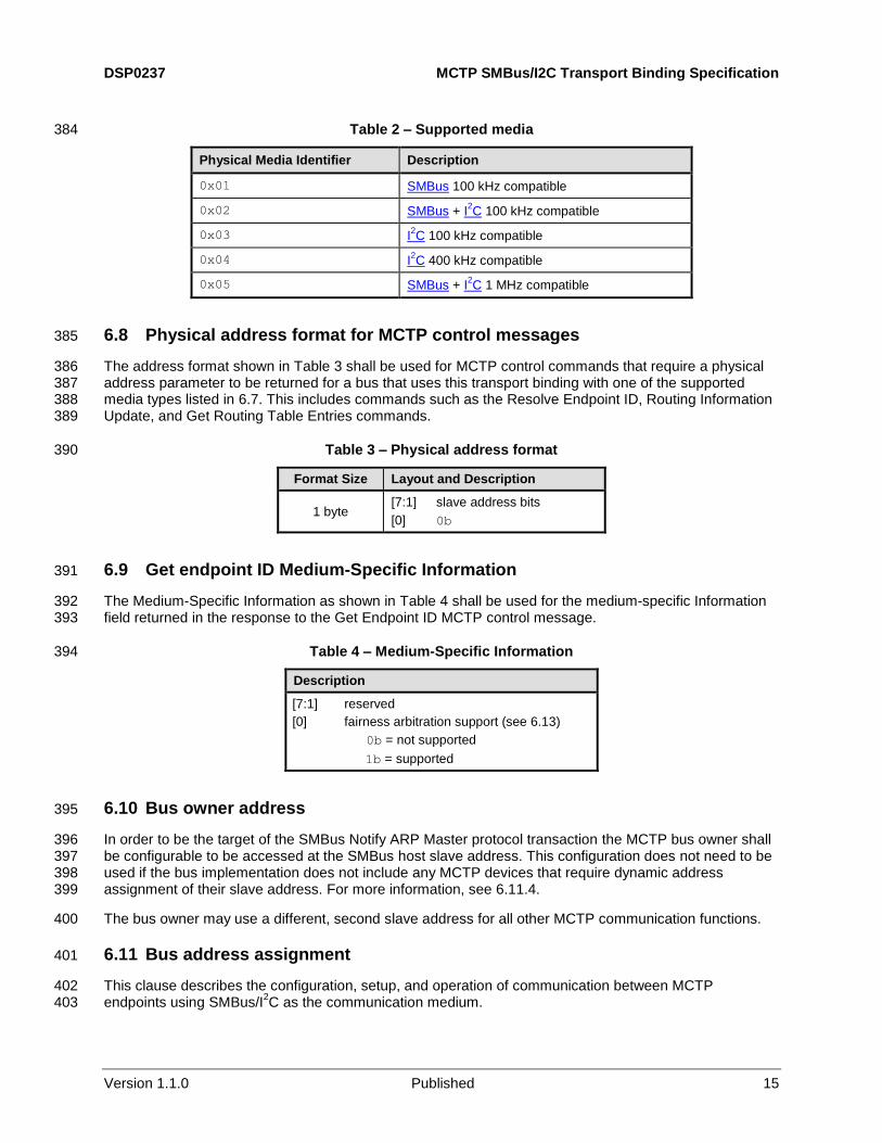
This physical transport binding has been designed to work with the media specified in DSP0239. Table 2 379 quotes relevant physical media identifiers from DSP0239. In case of any contradiction DSP0239 shall be 380 used as the normative definition. Use of this binding with other types of physical media is not covered by 381 this specification. At least one of the physical media identifiers listed in Table 2 shall be supported to 382 comply with this specification. 383
DSP0237 MCTP SMBus/I2C Transport Binding Specification
Version 1.1.0 Published 15
Table 2 – Supported media 384
Physical Media Identifier Description
0x01 SMBus 100 kHz compatible
0x02 SMBus + I2C 100 kHz compatible
0x03 I2C 100 kHz compatible
0x04 I2C 400 kHz compatible
0x05 SMBus + I2C 1 MHz compatible
6.8 Physical address format for MCTP control messages 385
The address format shown in Table 3 shall be used for MCTP control commands that require a physical 386 address parameter to be returned for a bus that uses this transport binding with one of the supported 387 media types listed in 6.7. This includes commands such as the Resolve Endpoint ID, Routing Information 388 Update, and Get Routing Table Entries commands. 389
Table 3 – Physical address format 390
Format Size Layout and Description
1 byte [7:1] slave address bits
[0] 0b
6.9 Get endpoint ID Medium-Specific Information 391
The Medium-Specific Information as shown in Table 4 shall be used for the medium-specific Information 392 field returned in the response to the Get Endpoint ID MCTP control message. 393
Table 4 – Medium-Specific Information 394
Description
[7:1] reserved
[0] fairness arbitration support (see 6.13)
0b = not supported
1b = supported
6.10 Bus owner address 395
In order to be the target of the SMBus Notify ARP Master protocol transaction the MCTP bus owner shall 396 be configurable to be accessed at the SMBus host slave address. This configuration does not need to be 397 used if the bus implementation does not include any MCTP devices that require dynamic address 398 assignment of their slave address. For more information, see 6.11.4. 399
The bus owner may use a different, second slave address for all other MCTP communication functions. 400
6.11 Bus address assignment 401
This clause describes the configuration, setup, and operation of communication between MCTP 402 endpoints using SMBus/I
2C as the communication medium. 403
MCTP SMBus/I2C Transport Binding Specification DSP0237
16 Published Version 1.1.0
6.11.1 Slave addresses 404
Each device on SMBus/I2C shall have a slave address to be the target of transactions by bus masters. 405
The MCTP transport protocol solely utilizes Master Write transactions to transfer MCTP packets between 406 MCTP endpoints. For endpoint "A" to send an MCTP packet to endpoint "B", endpoint A shall master the 407 bus and issue a Block-Write transaction to the slave address of endpoint B. Similarly, for endpoint B to 408 send an MCTP packet to endpoint A, it shall master the bus and issue a Block-Write transaction to the 409 slave address of endpoint A. Thus, bi-directional transfer of MCTP packets requires that both sides of the 410 communication have slave addresses. 411
Device support for slave addresses can be of two general types: fixed or assignable. Devices with 412 assignable addresses (also referred to as "ARP-capable" or "ARP-able") can use the SMBus ARP. The 413 entity that assigns slave addresses to ARP-able devices is referred to as the "ARP master". 414
A bus can include a mix of fixed-address and ARP-able devices. Most fixed-address devices do not 415 include a discovery mechanism, and neither SMBus nor I
2C require one. Therefore, for a generic bus 416
implementation that support ARP-able devices (such as SMBus to PCI/PCIe connectors) the ARP master 417 needs to know what ranges of addresses are being used for fixed-address devices so that it doesn’t give 418 an ARP-able device an address that conflicts with a fixed-address device. 419
This transport binding allows for non-MCTP devices (both fixed address and ARP-able) to reside on the 420 same bus segment used for MCTP devices. The use and assignment of slave addresses shall therefore 421 be compatible with pre-existing devices. To accomplish this, the following approach is used for managing 422 devices on a bus that supports MCTP. 423
6.11.2 Well known and reserved slave addresses 424
The SMBus and I2C specifications define certain slave addresses that should either be avoided by 425
devices or are reserved (not to be used as a general device slave address) because those addresses are 426 related to functions that are used by MCTP. These addresses are listed in Table 10. 427
6.11.3 Fixed-address recommendations for device manufacturers 428
MCTP may be used within a typical computer system application where the motherboard/baseboard may 429 come from one supplier, the chassis from another supplier, and possibly add-in modules from yet 430 another. 431
Referring to Table 11, it is thus recommended that devices that use fixed addresses and are targeted for 432 uses that can include baseboard (B), chassis/system (C), and add-in (A) applications are configurable to 433 cover for at least three different "B" addresses, at least three different "C" addresses, and at least two 434 different "A" addresses to help avoid address conflicts in those applications. 435
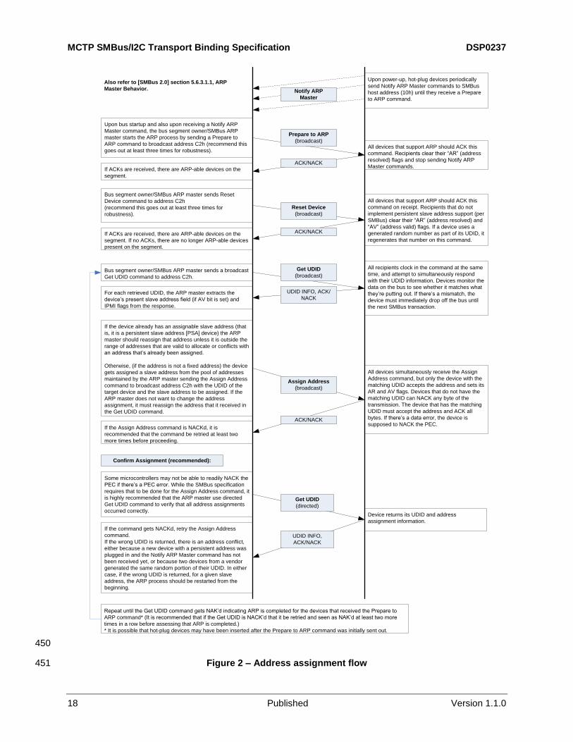
6.11.4 Dynamic address assignment (SMBus ARP) support 436
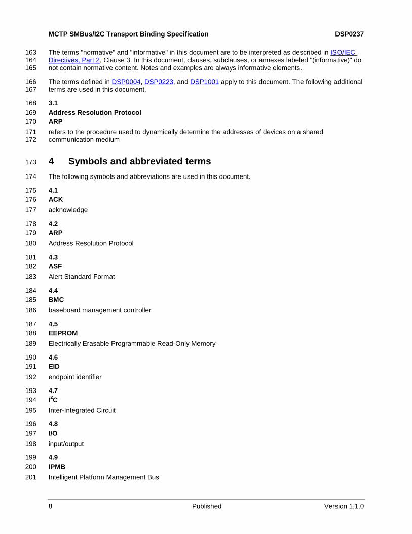
MCTP buses that support connections to standard PCI/PCIe add-in cards are required by the PCI 437 specifications to support SMBus ARP (be ARP-capable) to allow the devices to be dynamically assigned 438 addresses to avoid address conflicts and eliminate the need for manual configuration of addresses. 439 Figure 2 presents an overview of the address assignment process. 440
DSP0237 MCTP SMBus/I2C Transport Binding Specification
Version 1.1.0 Published 17
6.11.5 Devices supporting multiple interfaces 441
Devices that support multiple, separate SMBus or I2C interfaces where the interfaces are intended to be 442
connected to the same bus shall meet the following requirements: 443
The interfaces shall be either be ARP-capable or be fixed-address interfaces that are configured 444 to use a different slave address for each interface. 445
If the interfaces support SMBus ARP, (as either ARP-able or ARP-enumerable devices) a 446 different SMBus UDID shall be used for each SMBus ARP-able interface. 447
NOTE Devices that have internal hardware interfaces that may be implemented as separate blocks but are designed 448 to share a slave address are not considered to have separate interfaces in this context. 449
MCTP SMBus/I2C Transport Binding Specification DSP0237
18 Published Version 1.1.0
Upon bus startup and also upon receiving a Notify ARP
Master command, the bus segment owner/SMBus ARP
master starts the ARP process by sending a Prepare to
ARP command to broadcast address C2h (recommend this
goes out at least three times for robustness).
Upon power-up, hot-plug devices periodically
send Notify ARP Master commands to SMBus
host address (10h) until they receive a Prepare
to ARP command.
All devices that support ARP should ACK this
command. Recipients clear their “AR” (address
resolved) flags and stop sending Notify ARP
Master commands.
Bus segment owner/SMBus ARP master sends Reset
Device command to address C2h
(recommend this goes out at least three times for
robustness).
All devices that support ARP should ACK this
command on receipt. Recipients that do not
implement persistent slave address support (per
SMBus) clear their “AR” (address resolved) and
“AV” (address valid) flags. If a device uses a
generated random number as part of its UDID, it
regenerates that number on this command.
Bus segment owner/SMBus ARP master sends a broadcast
Get UDID command to address C2h.
All recipients clock in the command at the same
time, and attempt to simultaneously respond
with their UDID information. Devices monitor the
data on the bus to see whether it matches what
they’re putting out. If there’s a mismatch, the
device must immediately drop off the bus until
the next SMBus transaction.
For each retrieved UDID, the ARP master extracts the
device’s present slave address field (if AV bit is set) and
IPMI flags from the response.
If the device already has an assignable slave address (that
is, it is a persistent slave address [PSA] device) the ARP
master should reassign that address unless it is outside the
range of addresses that are valid to allocate or conflicts with
an address that’s already been assigned.
Otherwise, (if the address is not a fixed address) the device
gets assigned a slave address from the pool of addresses
maintained by the ARP master sending the Assign Address
command to broadcast address C2h with the UDID of the
target device and the slave address to be assigned. If the
ARP master does not want to change the address
assignment, it must reassign the address that it received in
the Get UDID command.
All devices simultaneously receive the Assign
Address command, but only the device with the
matching UDID accepts the address and sets its
AR and AV flags. Devices that do not have the
matching UDID can NACK any byte of the
transmission. The device that has the matching
UDID must accept the address and ACK all
bytes. If there’s a data error, the device is
supposed to NACK the PEC.
If ACKs are received, there are ARP-able devices on the
segment. If no ACKs, there are no longer ARP-able devices
present on the segment.
If ACKs are received, there are ARP-able devices on the
segment.
Repeat until the Get UDID command gets NAK’d indicating ARP is completed for the devices that received the Prepare to
ARP command* (It is recommended that if the Get UDID is NACK’d that it be retried and seen as NAK’d at least two more
times in a row before assessing that ARP is completed.)
* It is possible that hot-plug devices may have been inserted after the Prepare to ARP command was initially sent out.
If the Assign Address command is NACKd, it is
recommended that the command be retried at least two
more times before proceeding.
ACK/NACK
Assign Address
(broadcast)
UDID INFO, ACK/
NACK
Get UDID
(broadcast)
ACK/NACK
Reset Device
(broadcast)
Prepare to ARP
(broadcast)
ACK/NACK
Notify ARP
Master
Some microcontrollers may not be able to readily NACK the
PEC if there’s a PEC error. While the SMBus specification
requires that to be done for the Assign Address command, it
is highly recommended that the ARP master use directed
Get UDID command to verify that all address assignments
occurred correctly.Device returns its UDID and address
assignment information.
Get UDID
(directed)
UDID INFO,
ACK/NACK
If the command gets NACKd, retry the Assign Address
command.
If the wrong UDID is returned, there is an address conflict,
either because a new device with a persistent address was
plugged in and the Notify ARP Master command has not
been received yet, or because two devices from a vendor
generated the same random portion of their UDID. In either
case, if the wrong UDID is returned, for a given slave
address, the ARP process should be restarted from the
beginning.
Confirm Assignment (recommended):
Also refer to [SMBus 2.0] section 5.6.3.1.1, ARP
Master Behavior.
450
Figure 2 – Address assignment flow 451
DSP0237 MCTP SMBus/I2C Transport Binding Specification
Version 1.1.0 Published 19
6.11.6 MCTP requirements on SMBus ARP master support 452
If the bus supports ARP-able devices, MCTP requires that each bus shall have a controller that operates 453 as the ARP master and assigns slave addresses to all ARP-able devices on the segment. Because the 454 MCTP bus owner shall know the physical addresses of ARP-able devices that support MCTP, the ARP 455 master role will typically be handled by the same device that serves as the MCTP bus owner. 456
If a different physical device than the device holding the bus owner functions as the ARP master, there 457 shall be a mechanism to communicate the address assignment information to the bus owner function. 458 The mechanism for this is not specified by MCTP. 459
Only one controller is allowed to function as the ARP master for the segment at a given time. The ARP 460 master function is allowed to fail-over or be transferred to another controller. The mechanism for this 461 capability, if provided, is not specified by MCTP. 462
6.11.7 Recommendations on ARP master allocation of slave addresses 463
For PCI and PCI Express™ (PCIe) bus implementations, it is recommended that, by default, the ARP 464 master only assigns addresses to ARP-able devices from the "B" range. This is because the PCI 465 slots/connectors themselves are most commonly implemented as part of the board set. 466
Device manufacturers of controllers that function as ARP masters should provide a mechanism to enable 467 system integrators to either configure which fixed addresses that ARP should avoid, or a pool of non-468 conflicting addresses from which ARP can draw. 469
For PCI and PCIe SMBus implementations, the ARP master should be able to assign at least two 470 addresses for each PCI connector on the segment. 471
6.11.8 MCTP requirements on hot-pluggable bridges using SMBus 472
Hot-pluggable MCTP devices that include bridging functionality are required to have static, pre-assigned, 473 SMBus UDIDs. This is because it is considered a more robust and reliable mechanism than randomly 474 generated UDIDs, and because it simplifies tracking and managing MCTP device hot-add and hot-475 removal. 476
If devices regenerate their UDIDs on hot-plug, the MCTP bus owner/ARP master cannot rely on the UDID 477 to determine whether a device was newly added to the system. When a hot-plug device includes MCTP 478 bridging functionality, the bus owner shall be able to allocate the device a range of EIDs from a fixed pool 479 of IDs. Thus, it is important for the bus owner to be able to determine which devices have been removed 480 so that any EIDs it had given out can be returned to the pool. 481
It is straightforward for the ARP master to re-enumerate the UDIDs on the bus and determine which 482 UDIDs (if any) are no longer present (re-enumeration is a natural fallout of the ARP process). If there are 483 MCTP devices without fixed UDIDs in the mix, however, the bus owner would need to take additional 484 steps to check to see which devices had already been allocated EIDs to determine by elimination which 485 ranges, if any, had become freed. With fixed UDID, the bus owner can track which EIDs have been 486 allocated to which UDIDs and thereby determine which have been freed by a hot swap by just re-487 enumerating the UDIDs. 488
6.12 SMBus/I2C considerations for MCTP messages 489
The following applies to MCTP messages on SMBus regardless of their message type. Note that MCTP 490 messages require Block Write byte count sizes that exceed limits specified by SMBus. Additional 491 restrictions on MCTP packets over what the SMBus and I
2C allow are given in 6.3 and 6.18. 492
MCTP SMBus/I2C Transport Binding Specification DSP0237
20 Published Version 1.1.0
6.12.1 Slave address ACKs/NACKs 493
Per SMBus and I2C, the NACK of a slave address indicates the physical absence of the device interface. 494
Devices are therefore required to always ACK their slave addresses. This includes ACK'ing 495 slave addresses used for ARP if the device is ARP-able or ARP-enumerable. 496
An MCTP device shall ACK its slave address(es) when the R/W bit on the slave address is 0. 497
6.12.2 Clock stretching for non-addressed devices 498
MCTP devices that are monitoring the bus as slaves and do not have a slave address that matches the 499 transaction shall not clock stretch past the ACK bit for the slave address byte. This requirement only 500 applies to MCTP packet transactions. It does not apply to non-MCTP-defined messages or transactions, 501 such as those used for SMBus ARP. 502
6.13 Fairness arbitration 503
6.13.1 General 504
The following clauses describe an extension to the SMBus/I2C arbitration mechanism for device ports that 505
are used with MCTP. The extensions define a ‘fairness’ mechanism that helps ensure that ports that are 506 arbitrating for access to the bus will eventually get access and will not be locked out of access by other 507 MCTP ports that are using the bus. 508
NOTE Fairness arbitration only applies for messages using the MCTP base protocol. SMBus messages such as 509 Host Notify are not required to use fairness arbitration. 510
This mechanism works as follows: 511
An MCTP port that wins bus arbitration (per SMBus or I2C) for a given transaction shall wait 512
until it detects a particular bus idle interval before the device can again attempt to arbitrate for 513 the bus. This is referred to as the device waiting to detect the "FAIR_IDLE" condition. 514
Once the port has succeeded in detecting the FAIR_IDLE condition, it can attempt to get on the 515 bus and no longer needs to wait to detect the FAIR_IDLE condition. The port can continue to 516 attempt to access the bus without waiting for FAIR_IDLE until the next time the port wins 517 arbitration. After winning arbitration, the port shall again wait to detect the FAIR_IDLE condition 518 before it can attempt to get on the bus. 519
With this approach, all ports that lose arbitration will eventually get a turn at accessing the bus, because 520 any ports that win arbitration will need to wait until a bus idle interval is detected, while those that have 521 lost arbitration will not need to wait. 522
For this to work, endpoints shall be able to do two things: 523
1) Be able to recognize the FAIR_IDLE condition. Ports that are waiting to detect a FAIR_IDLE 524 condition shall recognize that no other port has made the bus become busy within a particular 525 window of time (TIDLE_WINDOW) after the bus becomes free. 526
2) Ports that have not won arbitration shall be able to issue a START condition soon enough after 527 the bus becomes free so that a bus busy condition is seen by ports that are waiting to detect a 528 FAIR_IDLE condition. To ensure this condition is met, START shall be issued by the port within 529 a particular window of time (TSTART_WINDOW) after the bus becomes free. 530
NOTE There is actually no explicit indication in SMBus or I2C that arbitration has been won. Instead, what the 531
master detects is that it was able to access the bus and did not have a collision (lose arbitration) with another master. 532 For this specification, this is referred to as winning arbitration. Because of the way arbitration works, an MCTP 533 endpoint that is transmitting as a master onto the bus will know that it has won arbitration if it is able to transmit from 534 the destination slave address byte through the end of the source slave address byte (byte 4) without receiving a 535 collision or NACK. 536
DSP0237 MCTP SMBus/I2C Transport Binding Specification
Version 1.1.0 Published 21
6.13.2 Deadlock avoidance with fairness arbitration 537
A device that wins arbitration but is subsequently NACK'd for its write transaction shall return to waiting 538 for the FAIR_IDLE period before it can attempt the transaction again. 539
6.13.3 Fairness arbitration support 540
Bridges and endpoints should support fairness arbitration. An endpoint's support for fairness arbitration 541 shall be reported through the medium-specific Information field in the response to the Get Endpoint ID 542 MCTP control message. 543
6.13.4 Bus busy sampling requirements for fairness arbitration 544
It is atypical and unlikely that the bus will go busy and then free again within TIDLE_WINDOW. This is because 545 TIDLE_WINDOW is shorter than the time required to send one byte on the bus. Thus, this condition would only 546 occur on an error or under a usage of the bus that is not legal within the specifications. Therefore, an 547 implementation is not required to continuously check the bus busy status during the entire duration of 548 TIDLE_WINDOW (though this is recommended). An implementation is allowed to check the bus busy status 549 only at the conclusion of the TIDLE_WINDOW interval that is measured by the device. 550
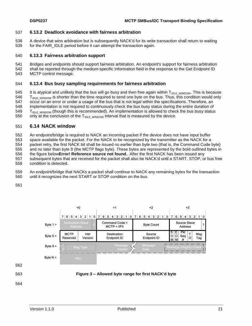
6.14 NACK window 551
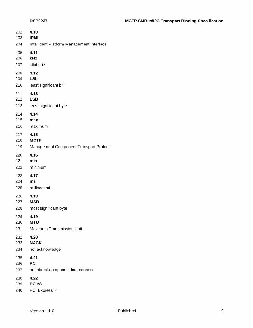
An endpoint/bridge is required to NACK an incoming packet if the device does not have input buffer 552 space available for the packet. For the NACK to be recognized by the transmitter as the NACK for a 553 packet retry, the first NACK bit shall be issued no earlier than byte two (that is, the Command Code byte) 554 and no later than byte 8 (the MCTP flags byte). These bytes are represented by the bold outlined bytes in 555 the figure belowError! Reference source not found.. After the first NACK has been issued any 556 subsequent bytes that are received for the packet shall also be NACK’d until a START, STOP, or bus free 557 condition is detected. 558
An endpoint/bridge that NACKs a packet shall continue to NACK any remaining bytes for the transaction 559 until it recognizes the next START or STOP condition on the bus. 560
561
0Destination Slave
Address
Source Slave
Address
MCTP
Reserved
S
O
M
Msg
Tag
Pkt
Seq
#
7
+0
6 5 4 3 2 1 0 7 6 5 4 3 2 1 0 7 6 5 4 3 2 1 0 7 6 5 4 3 2 1 0
+1 +2 +3
Byte 1 >
Byte 5 >
Byte 9 >
Byte N >
Message
Header
Message
Data
PEC
Msg TypeI
CMessage Integrity Check
Command Code =
MCTP = 0FhByte Count 1
Source
Endpoint ID
E
O
M
T
O
Hdr
Version
Destination
Endpoint ID
562
Figure 3 – Allowed byte range for first NACK'd byte 563
564
MCTP SMBus/I2C Transport Binding Specification DSP0237
22 Published Version 1.1.0
6.15 Fairness arbitration requirements for MCTP bridges 565
MCTP bridges that support fairness arbitration shall meet the following requirements: 566
The bridge shall support FAIR_IDLE detection and implement the corresponding fairness policy 567 separately for each port on the bridge. 568
Upon device power up or initialization, a port does not need to detect a FAIR_IDLE condition 569 before first attempting to access the bus. 570
A bridge that loses arbitration when attempting to transmit shall continue to retry the transaction 571 when the bus becomes free for up to PN2 retries (see Table 8). If the retry limit is reached, the 572 bridge shall drop the packet data. 573
A bridge that receives a NACK when attempting to transmit to a given physical address shall 574 continue to retry the transaction when the bus becomes free for up to PN2 retries. The bridge 575 will return to attempting to arbitrate for the bus as described in the preceding requirement, 576 restarting its number of arbitration retries. If the retry limit is reached, the bridge shall drop the 577 packet data. 578
An MCTP bridge shall provide dedicated input buffer space per port. The minimum input buffer 579 size is large enough to store one full baseline MTU-sized MCTP packet. It is recommended, but 580 not required, that a bridge also implement a dedicated output buffer per port, sized to store at 581 least one full baseline MTU-sized MCTP packet. 582
If the MCTP bridge is the target of an MCTP packet and it does not have enough buffer space in 583 its input buffer to store the full packet, it shall NACK the packet. If the bridge has an output 584 packet to transmit on that same port, it shall be able to issue a START within TSTART_WINDOW after 585 issuing the retry NACK. 586
A bridge is required to drop a received packet if it finds that the packet error code (PEC) byte for 587 the transaction is incorrect. 588
An MCTP bridge is not allowed to perform "connected" transactions where the decision to ACK 589 or NACK an incoming packet is dependent on the bridge’s ability to acquire the destination bus 590 prior to accepting the packet. 591
MCTP bridges are required to implement "store and forward" packet processing. That is, once a 592 bridge has accepted a packet for routing, it shall retain that packet until it can successfully 593 transmit it onto the target bus (except when running out of retries when trying to access the 594 target bus, or upon receiving a packet for a bus that is unavailable or an endpoint that is not 595 present.) 596
A bridge cannot make the acceptance of a receive packet on its upstream port (port that 597 connects to a bus that is not owned by the bridge itself) conditional on its ability to transmit a 598 packet on its upstream port. This requirement does not apply to a downstream port on a bridge 599 (that is, a downstream port may elect to NACK an incoming packet to allow the bridge to 600 transmit from that port). This requirement is to help avoid deadlock situations if a bridge is 601 required to route a packet back onto the bus from which the packet came. 602
A bridge that receives a NACK while it is performing a Master Write operation is not required to 603 immediately conclude the Master Write operation and drop off the bus. The bridge may continue 604 the write operation through its conclusion. In either case, the master shall always conclude its 605 transaction with a STOP condition, unless some other device on the bus first produces a 606 START or STOP condition. The latter situation is an erroneous condition on the bus, but bridges 607 shall be able to handle it. Devices shall always recognize START and STOP conditions 608 regardless of the transaction or bit position on which they occur. 609
DSP0237 MCTP SMBus/I2C Transport Binding Specification
Version 1.1.0 Published 23
6.16 Fairness arbitration requirements for non-bridge endpoints 610
Non-bridge/bus owner endpoints ("simple endpoints") are required to implement the MCTP fairness 611 arbitration extensions (when enabled) as follows: 612
The endpoint's port shall support FAIR_IDLE detection and implement the corresponding 613 fairness policy. 614
Upon device power up or initialization, the endpoint does not need to detect a FAIR_IDLE 615 condition before first attempting to access the bus. 616
The endpoint cannot make the acceptance of a receive packet conditional on its ability to 617 transmit a packet (that is, a simple endpoint shall not NACK incoming packets because it is 618 trying to send an outgoing packet). 619
Meeting this requirement may require the endpoint to have separate transmit and receive 620 buffers. This is the recommended implementation. 621
If a device is severely limited in buffer space and cannot allocate separate space for both 622 transmit and received data, options are for the endpoint to allow its buffer to be over-written by 623 the receive packet, or in some cases the endpoint may elect to do a dummy receive of the 624 incoming packet (that is, ACK the incoming bytes, but internally drop them as they are coming 625 in.) 626
Higher layer protocols shall be used to handle the case when the endpoint is targeted by more 627 messages than it can process. The buffering requirement for the MCTP Control Protocol 628 messages is defined in the MCTP Base Specification. Buffering requirements for other message 629 types are defined in the respective specifications for the message type. 630
An endpoint is allowed to NACK a packet if it is temporarily unable to accept it (for example, 631 because of an input buffer-full condition). This should typically only occur if the endpoint is the 632 target of packets from more than one source endpoint. 633
There is no direct limit of how long a non-bridge endpoint is allowed to successively NACK 634 incoming packets. However, there are limits on how many packet-level retries a transmitter will 635 attempt before it drops the transmitted packet, as well as message type-specific limits on how 636 long and how many times a given message will be retried. 637
If an endpoint has an output transmit packet and it NACKs an input receive packet from lack of 638 input buffer space, it shall be able to issue a START condition to transmit the output packet 639 within TSTART_WINDOW after the bus becomes free, unless the endpoint is waiting to detect TIDLE. 640
An endpoint that receives a NACK while it is performing a Master Write operation is not required 641 to immediately conclude the Master Write operation and drop off the bus. The endpoint may 642 continue the write operation through its conclusion. In either case, the master shall always 643 conclude its transaction with a STOP condition, unless some other device on the bus first 644 produces a START or STOP condition. The latter situation is an erroneous condition on the bus, 645 but bridges shall be able to handle it. Devices shall always recognize START and STOP 646 conditions regardless of the transaction or bit position on which they occur. 647
Endpoints that are NACK'd or lose arbitration shall retry transaction for PN1 retries (see 648 Table 8). 649
MCTP SMBus/I2C Transport Binding Specification DSP0237
24 Published Version 1.1.0
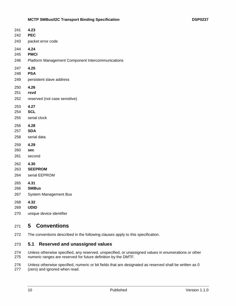
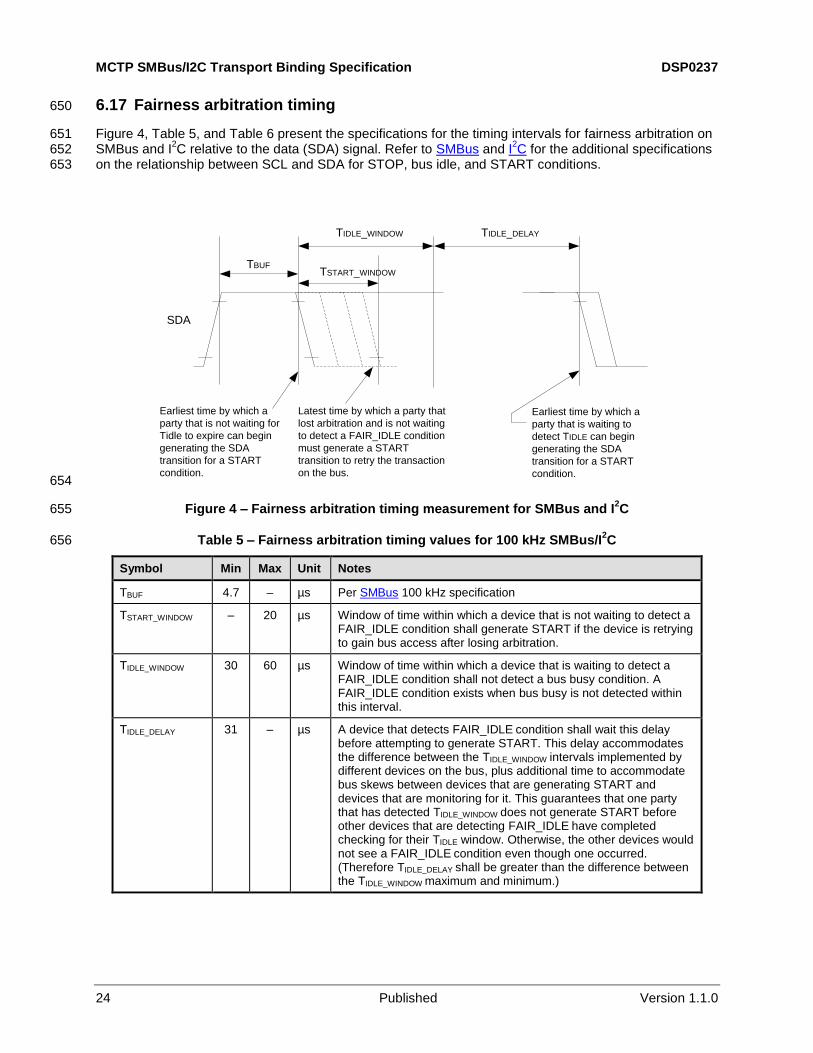
6.17 Fairness arbitration timing 650
Figure 4, Table 5, and Table 6 present the specifications for the timing intervals for fairness arbitration on 651 SMBus and I
2C relative to the data (SDA) signal. Refer to SMBus and I
2C for the additional specifications 652
on the relationship between SCL and SDA for STOP, bus idle, and START conditions. 653
TBUF
TIDLE_WINDOW
SDA
Latest time by which a party that
lost arbitration and is not waiting
to detect a FAIR_IDLE condition
must generate a START
transition to retry the transaction
on the bus.
Earliest time by which a
party that is not waiting for
Tidle to expire can begin
generating the SDA
transition for a START
condition.
Earliest time by which a
party that is waiting to
detect TIDLE can begin
generating the SDA
transition for a START
condition.
TSTART_WINDOW
TIDLE_DELAY
654
Figure 4 – Fairness arbitration timing measurement for SMBus and I2C 655
Table 5 – Fairness arbitration timing values for 100 kHz SMBus/I2C 656
Symbol Min Max Unit Notes
TBUF 4.7 – µs Per SMBus 100 kHz specification
TSTART_WINDOW – 20 µs Window of time within which a device that is not waiting to detect a FAIR_IDLE condition shall generate START if the device is retrying to gain bus access after losing arbitration.
TIDLE_WINDOW 30 60 µs Window of time within which a device that is waiting to detect a FAIR_IDLE condition shall not detect a bus busy condition. A FAIR_IDLE condition exists when bus busy is not detected within this interval.
TIDLE_DELAY 31 – µs A device that detects FAIR_IDLE condition shall wait this delay before attempting to generate START. This delay accommodates the difference between the TIDLE_WINDOW intervals implemented by different devices on the bus, plus additional time to accommodate bus skews between devices that are generating START and devices that are monitoring for it. This guarantees that one party that has detected TIDLE_WINDOW does not generate START before other devices that are detecting FAIR_IDLE have completed checking for their TIDLE window. Otherwise, the other devices would not see a FAIR_IDLE condition even though one occurred. (Therefore TIDLE_DELAY shall be greater than the difference between the TIDLE_WINDOW maximum and minimum.)
DSP0237 MCTP SMBus/I2C Transport Binding Specification
Version 1.1.0 Published 25
Table 6 – Fairness arbitration timing values for 400 kHz I2C 657
Symbol Min Max Unit Notes
TBUF 1.3 – µs Per I2C 400 kHz specification
TSTART_WINDOW – 4 µs Window of time within which a device that is not waiting to detect a FAIR_IDLE condition shall generate START if the device is retrying to gain bus access after losing arbitration.
TIDLE_WINDOW 5 20 µs Window of time within which a device that is waiting to detect a FAIR_IDLE condition shall not detect a bus busy condition. A FAIR_IDLE condition exists when bus busy is not detected within this.
TIDLE_DELAY 16 – µs A device that detects FAIR_IDLE condition shall wait for this delay before attempting to generate START. This delay accommodates the difference between the TIDLE_WINDOW intervals implemented by different devices on the bus, plus additional time to accommodate bus skews between devices that are generating START and devices that are monitoring for it. This guarantees that one party that has detected TIDLE does not generate START before other devices that are detecting TIDLE have completed their TIDLE window. Otherwise, the other devices would not see a FAIR_IDLE condition even though one occurred. (Therefore TIDLE_DELAY shall be greater than the difference between the TIDLE_WINDOW maximum and minimum.)
Table 7 – Fairness arbitration timing values for 1MHz I2C 658
Symbol Min Max Unit Notes
TBUF 0.5 – µs Per I2C 1MHz specification
TSTART_WINDOW – 2 µs Window of time within which a device that is not waiting to detect a FAIR_IDLE condition shall generate START if the device is retrying to gain bus access after losing arbitration.
TIDLE_WINDOW 3 6 µs Window of time within which a device that is waiting to detect a FAIR_IDLE condition shall not detect a bus busy condition. A FAIR_IDLE condition exists when bus busy is not detected within this interval.
TIDLE_DELAY 3.1 – µs A device that detects FAIR_IDLE condition shall wait this delay before attempting to generate START. This delay accommodates the difference between the TIDLE_WINDOW intervals implemented by different devices on the bus, plus additional time to accommodate bus skews between devices that are generating START and devices that are monitoring for it. This guarantees that one party that has detected TIDLE_WINDOW does not generate START before other devices that are detecting FAIR_IDLE have completed checking for their TIDLE window. Otherwise, the other devices would not see a FAIR_IDLE condition even though one occurred. (Therefore TIDLE_DELAY shall be greater than the difference between the TIDLE_WINDOW maximum and minimum.)
6.18 MCTP packet timing requirements 659
The timing specifications shown in Table 8 are specific to MCTP packet transfers on SMBus. Timing is 660 specified for a "point-to-point" connection. That is, timing is specified as if there were only two endpoints 661 in direct communication on the bus. In particular, the timing specifications assume that there is no clock 662 stretching that occurs due to other parties on the bus. 663

MCTP SMBus/I2C Transport Binding Specification DSP0237
26 Published Version 1.1.0
Table 8 – Timing specifications for MCTP packets on SMBus/I2C 664
Timing Specification Symbol Value Description
Endpoint packet level retries PN1 8
Number of times a non-bridge endpoint shall retry sending an MCTP packet upon receiving a NACK during the specified window (see Figure 3). An endpoint that gets successive NACKs shall do one retry for each NACK up to at least this number of retries. This also includes bridges when bridges are transmitting as an endpoint (as opposed to a bridge transmitting from its routing functionality).
Bridge packet level retries PN2 12 Number of times an MCTP bridge (when transmitting packet for routing) shall retry sending an MCTP packet upon receiving a NACK during the specified window (see 6.14 Error! Reference source not found.). A bridge
shall do one retry on each NACK up to this number.
Packet transaction originator duration
PT1a 250 μs per byte
[1]
The overall duration shall be less than the specified interval times the number of bytes in the packet, starting from the byte following the slave byte through and including the PEC byte. Individual data byte transmissions may exceed the specification provided the cumulative duration for the packet is met.
Originator slave address byte duration
PT1b 250 μs[1]
The amount of time, including any clock stretching, used to transmit the slave address, Wr, and ACK bits on the bus.
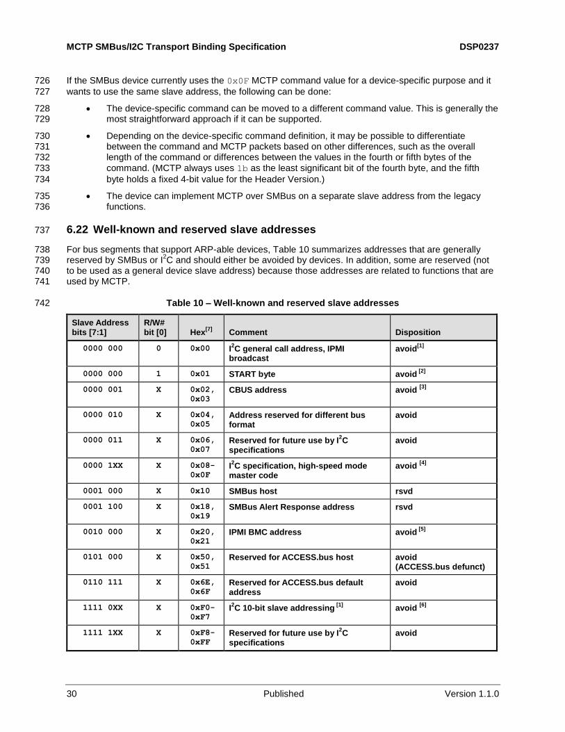
Slave-induced clock stretching PT1c 250 μs per byte
[1]
MCTP devices that are receiving MCTP packets shall not clock stretch the overall packet more than the specified amount.
Note that MCTP devices may share the bus with non-MCTP SMBus devices that cause clock stretching that exceeds this specification.
The PT2 parameters are intended to help guide a controller in determining when it is acceptable to initiate a Master Write transaction if the controller powers up or initializes itself on a bus segment that may already be active. It also helps controllers know when it is acceptable to continue under conditions where a STOP condition may have been lost because a controller dropped off the bus due to an error condition. An implementation shall meet at least one of specifications PT2a or PT2b.
Time-out waiting for bus free without seeing a STOP condition (Bus free determined by not detecting START or STOP)
PT2a 100 ms For controllers that have hardware that can only detect bus-free/busy-busy status by monitoring for START and STOP conditions, the controller can assume the bus is free if PT2a seconds goes by without detecting a START or STOP condition.
If a START condition is detected, the time-out interval restarts.
If a STOP condition is detected, the controller can assuming the bus is free following the TBUF interval specified in SMBus.
NOTE: This interval effectively places an upper limit on the duration of a single transaction. The byte count in an MCTP packet limits the size of the transaction to 260 bytes. 100 ms is more than sufficient to cover this transfer.
DSP0237 MCTP SMBus/I2C Transport Binding Specification
Version 1.1.0 Published 27
Timing Specification Symbol Value Description
Time-out waiting for bus free without seeing a STOP condition (Bus free determined by data/clock activity)
PT2b 50 μs The SMBus specification defines a bus-free (idle) condition as TBUF seconds after a STOP condition, or by the data and clock lines being high for PT2b seconds (where the value for PT2b is taken from THIGH, max as defined in SMBus).
If a controller has appropriate hardware support, monitoring PT2b and TBUF can be used to determine the bus-free (idle) condition in lieu of PT2a. This is generally the most efficient and highest performance way to detect bus free on SMBus.
SYSTEM IMPLEMENTATION NOTE: If "bit banged" I2C devices may be used on the same segment, it is
important to ensure that those devices do not drive the
clock and data high for more than THIGH, max seconds during transactions.
SDA Low TImeout PT3 2 sec min, 5 sec max
Time for a bus owner to monitor the SDA low level for a “Stuck 0” before attempting to clear the condition. (See 6.20.)
NOTE 1: Intervals include the ACK bit associated with the byte.
6.19 MCTP control message timing requirements 665
The following timing specifications are specific to MCTP control messages on SMBus/I2C. Timing is 666
specified for a "point-to-point" connection. That is, timing is specified as if there were only two endpoints 667 in direct communication on the bus. In particular, the timing specifications assume that there is no clock 668 stretching occurs due to other parties on the bus. 669
Response specifications are given assuming that the requester is able to operate at full speed on the bus. 670 That is, clock stretching, if any, is solely generated by the requester. 671
Responses are not retried. A "try" or "retry" of a request is defined as a complete transmission of the 672 MCTP control message. 673
Table 9 – Timing Specifications for MCTP control messages on SMBus 674
Timing Specification Symbol Min Max Description
Endpoint ID reclaim Treclaim 5 sec – Minimum time that a bus owner shall wait before reclaiming the EID for a non-responsive hot-plug endpoint.
Number of request retries
MN1 2 See descr.
Total of three tries, minimum: the original try plus two retries. The maximum number of retries for a given request is limited by the requirement that all retries shall occur within MT4, max of the initial request.
Request-to-response time
MT1 – 100 ms This interval is measured at the responder from the end of the reception of the MCTP Control Protocol request to the beginning of the transmission of the response. This requirement is tested under the condition where the responder can successfully transmit the response on the first try.
MCTP SMBus/I2C Transport Binding Specification DSP0237
28 Published Version 1.1.0
Timing Specification Symbol Min Max Description
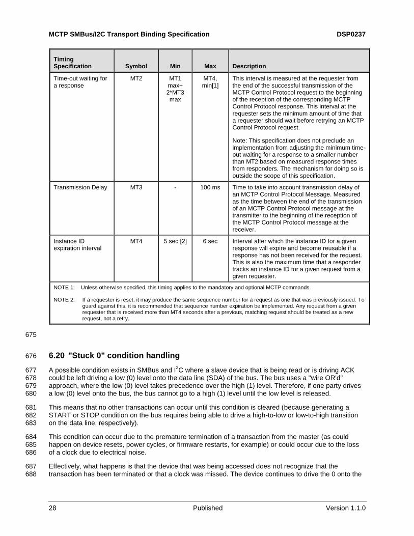
Time-out waiting for a response
MT2 MT1 max+ 2*MT3 max
MT4, min[1]
This interval is measured at the requester from the end of the successful transmission of the MCTP Control Protocol request to the beginning of the reception of the corresponding MCTP Control Protocol response. This interval at the requester sets the minimum amount of time that a requester should wait before retrying an MCTP Control Protocol request.
Note: This specification does not preclude an implementation from adjusting the minimum time-out waiting for a response to a smaller number than MT2 based on measured response times from responders. The mechanism for doing so is outside the scope of this specification.
Transmission Delay
MT3 - 100 ms Time to take into account transmission delay of an MCTP Control Protocol Message. Measured as the time between the end of the transmission of an MCTP Control Protocol message at the transmitter to the beginning of the reception of the MCTP Control Protocol message at the receiver.
Instance ID expiration interval
MT4 5 sec [2] 6 sec Interval after which the instance ID for a given response will expire and become reusable if a response has not been received for the request. This is also the maximum time that a responder tracks an instance ID for a given request from a given requester.
NOTE 1: Unless otherwise specified, this timing applies to the mandatory and optional MCTP commands.
NOTE 2: If a requester is reset, it may produce the same sequence number for a request as one that was previously issued. To guard against this, it is recommended that sequence number expiration be implemented. Any request from a given requester that is received more than MT4 seconds after a previous, matching request should be treated as a new request, not a retry.
675
6.20 "Stuck 0" condition handling 676
A possible condition exists in SMBus and I2C where a slave device that is being read or is driving ACK 677
could be left driving a low (0) level onto the data line (SDA) of the bus. The bus uses a "wire OR'd" 678 approach, where the low (0) level takes precedence over the high (1) level. Therefore, if one party drives 679 a low (0) level onto the bus, the bus cannot go to a high (1) level until the low level is released. 680
This means that no other transactions can occur until this condition is cleared (because generating a 681 START or STOP condition on the bus requires being able to drive a high-to-low or low-to-high transition 682 on the data line, respectively). 683
This condition can occur due to the premature termination of a transaction from the master (as could 684 happen on device resets, power cycles, or firmware restarts, for example) or could occur due to the loss 685 of a clock due to electrical noise. 686
Effectively, what happens is that the device that was being accessed does not recognize that the 687 transaction has been terminated or that a clock was missed. The device continues to drive the 0 onto the 688
DSP0237 MCTP SMBus/I2C Transport Binding Specification
Version 1.1.0 Published 29
bus because it is waiting to get more clocks from the master to conclude the transaction, but those clocks 689 will never come unless some bus master takes steps to generate them. 690
The solution to this condition is to have a master clock the bus until the SDA line goes high, at which point 691 the master can issue a START or STOP condition to get the bus back in synchronization. 692
To accomplish this, the master needs to be able to access and clock the bus without paying attention to 693 the present state of the SDA line. 694
Many microcontrollers have the ability to have firmware dynamically reconfigure their SMBus pins as 695 general purpose I/O pins. If this is supported, it is straightforward for firmware to generate the necessary 696 clocks on the SCL line by bypassing the SMBus controller hardware and using programmed I/O to control 697 the pins instead. The firmware would then simply clock the bus until it sees a "1" condition on the SDA 698 line and then a new SMBus transaction can be launched. 699
NOTE It is recommended that MCTP bus owners include a provision to detect and clear Stuck 0 conditions on 700 SMBus buses that they own. The controller should do this if it can detect that a constant 0 condition has existed on 701 the SDA line for more than PT3 seconds. 702
6.21 MCTP over SMBus/I2C protocol anti-aliasing 703
MCTP over SMBus has been designed to allow one endpoint to support multiple protocols, such as ASF, 704 IPMI, or legacy device-specific protocols with a single slave address. The following clauses describe 705 provisions that can help support implement MCTP over SMBus in devices that also need to support other 706 SMBus or I
2C protocols. 707
6.21.1 IPMI 708
The IPMI protocols for SMBus (IPMI over SMBus) and I2C (Intelligent Platform Management Bus, IPMB) 709
use the fourth byte of the transaction as a Source Slave Address byte, as does MCTP over SMBus. 710
However, the IPMI protocols require the least significant bit of that byte to be 0b, whereas MCTP over 711
SMBus requires the bit to be 1b. Thus, a device that needs to differentiate between MCTP over SMBus 712
and the IPMI SMBus/I2C protocols can do so using that bit. 713
6.21.2 ASF 714
MCTP over SMBus uses the ASF specification reserved value of 0x0F for the command byte. Thus, the 715
ASF-defined commands that use SMBus block-write protocol can be differentiated from MCTP over 716 SMBus block-write using the command byte value. If necessary, other ASF SMBus write transactions, 717 such as those for legacy sensor and control access can be differentiated from MCTP packets based on 718 the length of the transaction. The ASF transactions are all shorter. 719
6.21.3 Integrating MCTP with legacy SMBus functions 720
This clause describes some possible options if MCTP is being added to a device that shall also support 721 functions using a non-MCTP SMBus interface. 722
In general, there should be no problems having those functions co-exist with MCTP provided that the 723 legacy SMBus operations do not require generating or accepting write transactions that use the MCTP 724
value of 0x0F. 725
MCTP SMBus/I2C Transport Binding Specification DSP0237
30 Published Version 1.1.0
If the SMBus device currently uses the 0x0F MCTP command value for a device-specific purpose and it 726
wants to use the same slave address, the following can be done: 727
The device-specific command can be moved to a different command value. This is generally the 728 most straightforward approach if it can be supported. 729
Depending on the device-specific command definition, it may be possible to differentiate 730 between the command and MCTP packets based on other differences, such as the overall 731 length of the command or differences between the values in the fourth or fifth bytes of the 732
command. (MCTP always uses 1b as the least significant bit of the fourth byte, and the fifth 733
byte holds a fixed 4-bit value for the Header Version.) 734
The device can implement MCTP over SMBus on a separate slave address from the legacy 735 functions. 736
6.22 Well-known and reserved slave addresses 737
For bus segments that support ARP-able devices, Table 10 summarizes addresses that are generally 738 reserved by SMBus or I
2C and should either be avoided by devices. In addition, some are reserved (not 739
to be used as a general device slave address) because those addresses are related to functions that are 740 used by MCTP. 741
Table 10 – Well-known and reserved slave addresses 742
Slave Address bits [7:1]
R/W# bit [0] Hex
[7] Comment Disposition
0000 000 0 0x00 I2C general call address, IPMI
broadcast avoid
[1]
0000 000 1 0x01 START byte avoid [2]
0000 001 X 0x02,
0x03 CBUS address avoid
[3]
0000 010 X 0x04,
0x05 Address reserved for different bus format
avoid
0000 011 X 0x06,
0x07 Reserved for future use by I
2C
specifications avoid
0000 1XX X 0x08-
0x0F I2C specification, high-speed mode
master code avoid
[4]
0001 000 X 0x10 SMBus host rsvd
0001 100 X 0x18,
0x19 SMBus Alert Response address rsvd
0010 000 X 0x20,
0x21 IPMI BMC address avoid
[5]
0101 000 X 0x50,
0x51 Reserved for ACCESS.bus host avoid
(ACCESS.bus defunct)
0110 111 X 0x6E,
0x6F Reserved for ACCESS.bus default address
avoid
1111 0XX X 0xF0-
0xF7 I2C 10-bit slave addressing
[1] avoid
[6]
1111 1XX X 0xF8-
0xFF Reserved for future use by I
2C
specifications avoid
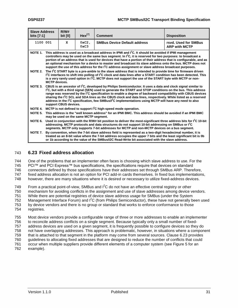
DSP0237 MCTP SMBus/I2C Transport Binding Specification
Version 1.1.0 Published 31
Slave Address bits [7:1]
R/W# bit [0] Hex
[7] Comment Disposition
1100 001 X 0xC2,
0xC3 SMBus Device Default address rsvd. Used for SMBus
ARP with MCTP
NOTE 1. This address is used as a broadcast address in IPMI and I2C. It should be avoided if IPMI management
controllers may be used on the same bus segment. In I2C, it is reserved for two purposes: to broadcast a
portion of an address that is used for devices that have a portion of their address that is configurable, and as an optional mechanism for a device to master and broadcast its slave address onto the bus. MCTP does not support the use of this address for the I
2C address assignment or slave address broadcast purposes.
NOTE 2. The I2C START byte is a pre-amble to the slave address that is intended to provide time for firmware driven
I2C interfaces to shift into polling of I
2C clock and data lines after a START condition has been detected. This
is a very rarely used option in I2C. MCTP does not support the use of the START byte with MCTP or non-
MCTP devices.
NOTE 3. CBUS is an ancestor of I2C, developed by Philips Semiconductor. It uses a data and clock signal similar to
I2C, but with a third signal (SEN) used to generate the START and STOP conditions on the bus. This address
range was reserved by the I2C specification to enable a degree of backward compatibility with CBUS devices
sharing the I2C SCL and SDA lines as the CBUS clock and data lines, respectively. While listed as a reserved
address in the I2C specification, few SMBus/I
2C implementations using MCTP will have any need to also
support CBUS devices.
NOTE 4. MCTP is not defined to support I2C high-speed mode operation.
NOTE 5. This address is the "well known address" for an IPMI BMC. This address should be avoided if an IPMI BMC may be used on the same MCTP segment.
NOTE 6. Used in conjunction with the R/W# bit position to deliver the most-significant three address bits for I2C 10-bit
addressing. MCTP protocols and data structures do not support 10-bit addressing on SMBus or I2C
segments. MCTP only supports 7-bit addresses for MCTP and non-MCTP devices on a bus segment.
NOTE 7. By convention, when the 7-bit slave address field is represented as a two-digit hexadecimal number, it is treated as an 8-bit value where the 7-bit address occupies the upper 7 bits and the least significant bit is 0b or 1b according to the value of the SMBus/I2C Read-Write bit associated with the slave address.
6.23 Fixed address allocation 743
One of the problems that an implementer often faces is choosing which slave address to use. For the 744 PCI™ and PCI Express™ bus specifications, the specifications require that devices on standard 745 connectors defined by those specifications have their addresses set through SMBus ARP. Therefore, 746 fixed address allocation is not an option for PCI add-in cards themselves. In fixed bus implementations, 747 however, there are many situations where it is desired or necessary to utilize fixed-address devices. 748
From a practical point-of-view, SMBus and I2C do not have an effective central registry or other 749
mechanism for avoiding conflicts in the assignment and use of slave addresses among device vendors. 750 While there are potential registries of device slave address usage for SMBus (under the System 751 Management Interface Forum) and I
2C (from Philips Semiconductor), these have not generally been used 752
by device vendors and there is no group or standard that works to enforce conformance to those 753 registries. 754
Most device vendors provide a configurable range of three or more addresses to enable an implementer 755 to reconcile address conflicts on a single segment. Because typically only a small number of fixed-756 address devices are used on a given segment, it is frequently possible to configure devices so they do 757 not have overlapping addresses. This approach is problematic, however, in situations where a component 758 that is attached to that segment in the platform may come from several sources. Clause 6.23 provides 759 guidelines to allocating fixed addresses that are designed to reduce the number of conflicts that could 760 occur when multiple suppliers provide different elements of a computer system (see Figure 5 for an 761 example). 762
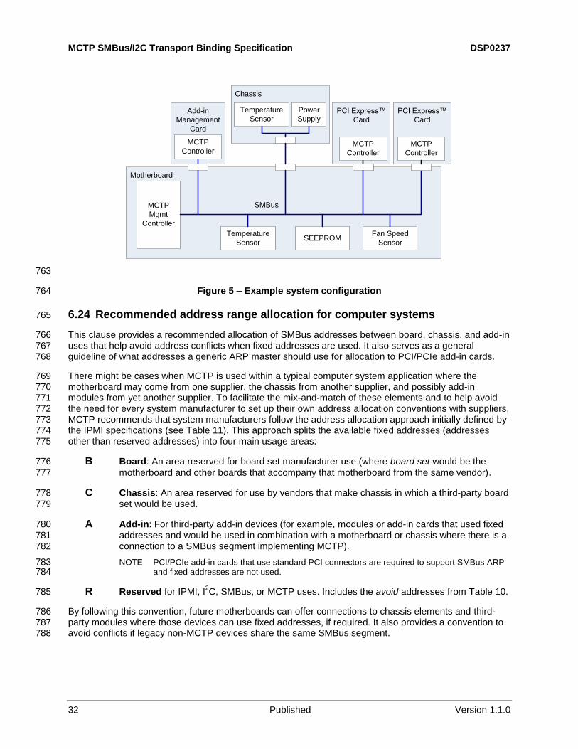
MCTP SMBus/I2C Transport Binding Specification DSP0237
32 Published Version 1.1.0
Motherboard
MCTP
Mgmt
Controller
Chassis
Add-in
Management
Card
Temperature
SensorPCI Express™
Card
PCI Express™
Card
MCTP
ControllerMCTP
Controller
MCTP
Controller
Temperature
SensorSEEPROM
Fan Speed
Sensor
Power
Supply
SMBus
763
Figure 5 – Example system configuration 764
6.24 Recommended address range allocation for computer systems 765
This clause provides a recommended allocation of SMBus addresses between board, chassis, and add-in 766 uses that help avoid address conflicts when fixed addresses are used. It also serves as a general 767 guideline of what addresses a generic ARP master should use for allocation to PCI/PCIe add-in cards. 768
There might be cases when MCTP is used within a typical computer system application where the 769 motherboard may come from one supplier, the chassis from another supplier, and possibly add-in 770 modules from yet another supplier. To facilitate the mix-and-match of these elements and to help avoid 771 the need for every system manufacturer to set up their own address allocation conventions with suppliers, 772 MCTP recommends that system manufacturers follow the address allocation approach initially defined by 773 the IPMI specifications (see Table 11). This approach splits the available fixed addresses (addresses 774 other than reserved addresses) into four main usage areas: 775
B Board: An area reserved for board set manufacturer use (where board set would be the 776
motherboard and other boards that accompany that motherboard from the same vendor). 777
C Chassis: An area reserved for use by vendors that make chassis in which a third-party board 778
set would be used. 779
A Add-in: For third-party add-in devices (for example, modules or add-in cards that used fixed 780
addresses and would be used in combination with a motherboard or chassis where there is a 781 connection to a SMBus segment implementing MCTP). 782
NOTE PCI/PCIe add-in cards that use standard PCI connectors are required to support SMBus ARP 783 and fixed addresses are not used. 784
R Reserved for IPMI, I2C, SMBus, or MCTP uses. Includes the avoid addresses from Table 10. 785
By following this convention, future motherboards can offer connections to chassis elements and third-786 party modules where those devices can use fixed addresses, if required. It also provides a convention to 787 avoid conflicts if legacy non-MCTP devices share the same SMBus segment. 788
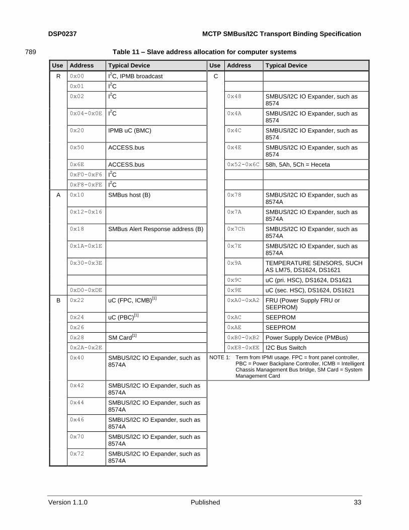
DSP0237 MCTP SMBus/I2C Transport Binding Specification
Version 1.1.0 Published 33
Table 11 – Slave address allocation for computer systems 789
Use Address Typical Device Use Address Typical Device
R 0x00 I2C, IPMB broadcast C
0x01 I2C
0x02 I2C 0x48 SMBUS/I2C IO Expander, such as
8574
0x04-0x0E I2C 0x4A SMBUS/I2C IO Expander, such as
8574
0x20 IPMB uC (BMC) 0x4C SMBUS/I2C IO Expander, such as 8574
0x50 ACCESS.bus 0x4E SMBUS/I2C IO Expander, such as 8574
0x6E ACCESS.bus 0x52-0x6C 58h, 5Ah, 5Ch = Heceta
0xF0-0xF6 I2C
0xF8-0xFE I2C
A 0x10 SMBus host (B) 0x78 SMBUS/I2C IO Expander, such as 8574A
0x12-0x16 0x7A SMBUS/I2C IO Expander, such as 8574A
0x18 SMBus Alert Response address (B) 0x7Ch SMBUS/I2C IO Expander, such as 8574A
0x1A-0x1E 0x7E SMBUS/I2C IO Expander, such as 8574A
0x30-0x3E 0x9A TEMPERATURE SENSORS, SUCH AS LM75, DS1624, DS1621
0x9C uC (pri. HSC), DS1624, DS1621
0xD0-0xDE 0x9E uC (sec. HSC), DS1624, DS1621
B 0x22 uC (FPC, ICMB)[1]
0xA0-0xA2 FRU (Power Supply FRU or SEEPROM)
0x24 uC (PBC)[1]
0xAC SEEPROM
0x26 0xAE SEEPROM
0x28 SM Card[1]
0xB0-0xB2 Power Supply Device (PMBus)
0x2A-0x2E 0xE8-0xEE I2C Bus Switch
0x40 SMBUS/I2C IO Expander, such as 8574A
NOTE 1: Term from IPMI usage. FPC = front panel controller, PBC = Power Backplane Controller, ICMB = Intelligent Chassis Management Bus bridge, SM Card = System Management Card
0x42 SMBUS/I2C IO Expander, such as 8574A
0x44 SMBUS/I2C IO Expander, such as 8574A
0x46 SMBUS/I2C IO Expander, such as 8574A
0x70 SMBUS/I2C IO Expander, such as 8574A
0x72 SMBUS/I2C IO Expander, such as 8574A
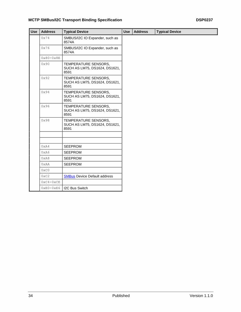
MCTP SMBus/I2C Transport Binding Specification DSP0237
34 Published Version 1.1.0
Use Address Typical Device Use Address Typical Device
0x74 SMBUS/I2C IO Expander, such as 8574A
0x76 SMBUS/I2C IO Expander, such as 8574A
0x80-0x8E
0x90 TEMPERATURE SENSORS, SUCH AS LM75, DS1624, DS1621, 8591
0x92 TEMPERATURE SENSORS, SUCH AS LM75, DS1624, DS1621, 8591
0x94 TEMPERATURE SENSORS, SUCH AS LM75, DS1624, DS1621, 8591
0x96 TEMPERATURE SENSORS, SUCH AS LM75, DS1624, DS1621, 8591
0x98 TEMPERATURE SENSORS, SUCH AS LM75, DS1624, DS1621, 8591
0xA4 SEEPROM
0xA6 SEEPROM
0xA8 SEEPROM
0xAA SEEPROM
0xC0
0xC2 SMBus Device Default address
0xC4-0xCE
0xE0-0xE6 I2C Bus Switch
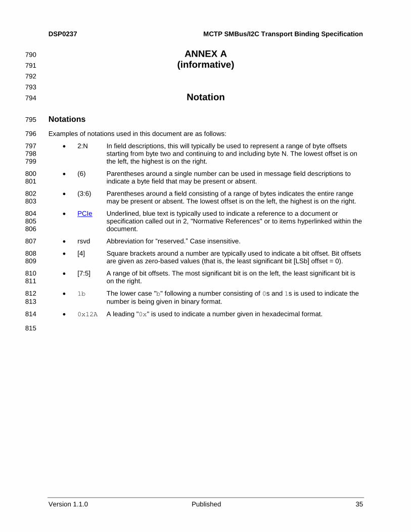
DSP0237 MCTP SMBus/I2C Transport Binding Specification
Version 1.1.0 Published 35
ANNEX A 790
(informative) 791
792
793
Notation 794
Notations 795
Examples of notations used in this document are as follows: 796
2:N In field descriptions, this will typically be used to represent a range of byte offsets 797 starting from byte two and continuing to and including byte N. The lowest offset is on 798 the left, the highest is on the right. 799
(6) Parentheses around a single number can be used in message field descriptions to 800 indicate a byte field that may be present or absent. 801
(3:6) Parentheses around a field consisting of a range of bytes indicates the entire range 802 may be present or absent. The lowest offset is on the left, the highest is on the right. 803
PCIe Underlined, blue text is typically used to indicate a reference to a document or 804 specification called out in 2, "Normative References" or to items hyperlinked within the 805 document. 806
rsvd Abbreviation for “reserved.” Case insensitive. 807
[4] Square brackets around a number are typically used to indicate a bit offset. Bit offsets 808 are given as zero-based values (that is, the least significant bit [LSb] offset = 0). 809
[7:5] A range of bit offsets. The most significant bit is on the left, the least significant bit is 810 on the right. 811
1b The lower case "b" following a number consisting of 0s and 1s is used to indicate the 812
number is being given in binary format. 813
0x12A A leading "0x" is used to indicate a number given in hexadecimal format. 814
815
MCTP SMBus/I2C Transport Binding Specification DSP0237
36 Published Version 1.1.0
ANNEX B 816
(informative) 817
818
819
Change log 820
Version Date Description
1.0.0 2009-07-28
1.1.0 2017-05-21 Added 1MHz speed mode
Moved NACK window to a separate section
Corrected timing parameters description
Updated reserved addresses mapping in Table 11
Updated Table 2
Updated revisions for the normative references
821