major modification
TRANSCRIPT

New Cingular Wireless PCS, LLC (KNKN856) New York 1 - Jefferson CMA 559A
FCC Form 601 Attachment 1
Major Modification DEMONSTRATION OF APPLICANT'S QUALIFICATIONS Pursuant to Section 22.107(a), New Cingular Wireless PCS, LLC ("Applicant"), a subsidiary of AT&T Inc. ("AT&T"), is qualified to hold Commission licenses, as has previously been determined. Pursuant to Section 1.919, Applicant relies on the current FCC Form 602 of Applicant, AT&T, or AT&T Mobility, LLC. PUBLIC INTEREST STATEMENT As required by Section 22.107(b), Applicant, the A-block cellular licensee in the New York 1 - Jefferson CMA (559A), herein proposes to add, modify and/or delete cell sites, as detailed in the attached Schedule Ds. No sites involve any environmental action requiring FCC approval. Taken together, these sites improve coverage within the CMA, providing increased capacity and continued high quality cellular service. Accordingly, the public interest, convenience, and necessity will be served by grant of this application. OPERATION OF FACILITY As required pursuant to Section 22.107(d), the existing facilities will operate in compliance with all rules governing the Public Mobile service. EXISTING CGSA DETERMINATION The existing Cellular Geographic Service Area ("CGSA") shown on the attached map was derived from the most-recent CGSA submission filed with the Commission for this Call Sign. CGSA REVISIONS The revisions proposed in this application expand Applicant’s CGSA
within the CMA , and into CMA053
the expanded CGSA includes areas adjacent to existing coverage
and includes areas less than 50 square miles currently being served on a secondary basis where the Applicant is now seeking protection
and includes areas currently being served on a secondary basis that are greater than 50 square miles where the Applicant is now seeking protection
This application proposes CGSA expansion into an area of >50 square miles that is currently unserved. As demonstrated in Applicant’s previous modification applications that have been granted for this license, Applicant’s existing, previously approved SAB covers the area of proposed expansion, though Applicant is only now seeking a CGSA expansion into the area. The alterations to the CGSA proposed in this application are depicted in the attached map provided in accordance with Section 22.929(c). Because the application expands the existing CGSA, it has been designated a Phase II application. The service area boundaries for the sites in this application were developed in accordance with Section 22.911(a). The engineering calculations use a minimum of 98' HAAT, per FCC Rule 22.911(a)(3), and 0.1 Watt or 27 db less than maximum ERP, per FCC Rule 22.911(a)(4). Site specific information is provided below and polar antenna radiation patterns are appended hereto. Applicant acknowledges that grant of this application does not convey the right to interference protection for the service area other than the defined CGSA. SAB EXTENSION AGREEMENTS This application includes SAB extensions into one or more adjacent CGSAs. Applicant or its affiliate is either the licensee of the adjacent CGSAs into which the SAB extends, and therefore no written SAB extension agreement is required, or Applicant has the required written SAB extension agreement in its files. ADMINISTRATIVE INFORMATION This application is for primary status for sites detailed in the Schedule Ds. The five-year build out period for all markets involved has expired. TECHNICAL INFORMATION Pursuant to Section 22.953(a)(3), the radial distance from the cell-transmitting antenna to its SAB has been calculated in accordance with Section 22.911(a). FULL-SIZE 1:500,000 SCALE MAP & REDUCED 8.5” X 11” MAP In accordance with Sections 22.929(c) and 22.953(a)(2), attached to this exhibit is a reduced 8.5” x 11” map, which includes the existing 32 dBu contours of the new sites. Also filed electronically with and as a part of this Application is the full-scale copy of the system map, as required by Sections 22.929(c) and 22.953(a)(1). [1] See Applications of AT&T Inc. and Cellco Partnership d/b/a Verizon Wireless, For Consent to Assign or Transfer Control of Licenses and Authorizations and Modify a Spectrum Leasing Arrangement, WT Docket No. 09-104, Memorandum Opinion and Order, 25 FCC Rcd 8704 (2010).

New Cingular Wireless PCS, LLC (KNKN856) New York 1 - Jefferson CMA 559A
FCC Form 601 Attachment 1
Site information
Sit
e N
am
e
TX
UL
S L
ocati
on
Nu
mb
er
UL
S L
ocati
on
Acti
on
(A
/M/D
)
Lati
tud
e
Lo
ng
itu
de
(P)r
op
osed
or
(E)x
isti
ng
Sit
e
UL
S A
nte
nn
a
Nu
mb
er
UL
S A
nte
nn
a
Acti
on
(A
/M/D
)
Max E
RP
(W
att
s)
Rad
Cen
terl
ine
(m)
Tip
Heig
ht
(m)
An
ten
na D
ata
Sh
eet
Ref
Site Location Data Site Antenna Specific Data
Stillwater Reservoir 453G11200 28 M 43-53-35.0 N 75-02-44.0 W E 1 M 173.9 14 15.7 ASPD952
Clayton 463G30031 3 M 44-15-03.2 N 76-01-49.4 W E 1 M 229.1 91.5 92.7 DBXLH-9090C-VTM
463G30032 2 M 354.9 91.5 92.7 DBXLH-9090C-VTM
463G30033 3 M 229.1 91.5 92.7 DBXLH-9090C-VTM
Adams 463G30051 A 43-49-13.2 N 76-05-16.1 W E 1 A 363.2 91.5 92.7 DBXLH-9090C-VTM
463G30052 2 A 426.7 91.5 92.8 DBXLH-6565C-VTM
463G30053 3 A 354.9 91.5 92.7 DBXLH-9090C-VTM
Crown Orleans 463G30091 A 44-17-23.4 N 75-57-58.6 W E 1 A 269.3 54 55.2 DBXLH-9090C-VTM
463G30092 2 A 426.7 54 55.2 DBXLH-9090C-VTM
463G30093 3 A 275.5 54 55.2 DBXLH-9090C-VTM
Massena 463G30101 12 M 44-55-50.7 N 74-56-48.5 W E 1 M 141.4 91.5 92.7 DBXLH-9090C-VTM
463G30102 2 M 63.1 91.5 92.7 DBXLH-9090C-VTM
463G30103 3 M 158.5 91.5 92.7 DBXLH-9090C-VTM
Waddington 463G30171 18 M 44-51-13.3 N 75-10-06.9 W E 1 M 269.3 57.3 58.5 DBXLH-9090C-VTM
463G30172 2 M 426.7 57.3 58.5 DBXLH-9090C-VTM
463G30173 3 M 269.3 57.3 58.5 DBXLH-9090C-VTM
Nicholville 463G30191 11 M 44-42-42.7 N 74-38-47.1 W E 1 M 190.6 54.6 55.8 DBXLH-9090C-VTM
463G30192 2 M 199.6 54.6 55.8 DBXLH-9090C-VTM
463G30193 3 M 195.0 54.6 55.8 DBXLH-9090C-VTM
Gomer Hill 463G30201 29 M 43-38-54.6 N 75-28-59.1 W E 1 M 371.7 33.8 35 DBXLH-9090C-VTM
463G30202 2 A 389.2 33.8 35 DBXLH-9090C-VTM
463G30203 3 A 371.7 33.8 35 DBXLH-9090C-VTM
Barnes Corners 463G30210 9 M 43-48-38.4 N 75-48-34.6 W E 1 M 144.6 56.1 57.8 ASPD952
Cape Vincent 463G30231 25 M 44-08-12.2 N 76-17-41.9 W E 1 M 173.9 54.6 55.8 DBXLH-9090C-VTM
463G30232 2 M 446.8 54.6 55.8 DBXLH-9090C-VTM
463G30233 3 M 275.5 54.6 55.8 DBXLH-9090C-VTM
Ogdensburg 463G30251 A 44-39-00.3 N 75-27-20.6 W E 1 A 436.7 54.9 56.1 DBXLH-9090C-VTM
463G30252 2 A 436.7 54.9 56.1 DBXLH-9090C-VTM
463G30253 3 A 436.7 54.9 56.1 DBXLH-9090C-VTM
Morristown 463G30261 17 M 44-32-21.5 N 75-36-43.7 W E 1 M 426.7 54 55.2 DBXLH-9090C-VTM
463G30262 2 A 426.7 54 55.2 DBXLH-9090C-VTM
463G30263 3 A 426.7 54 55.2 DBXLH-9090C-VTM
Pine Grove 463G30271 19 M 44-46-14.2 N 75-17-40.7 W E 1 M 275.5 57.3 58.5 DBXLH-9090C-VTM
463G30272 2 M 436.7 57.3 58.5 DBXLH-9090C-VTM
463G30273 3 M 275.5 57.3 58.5 DBXLH-9090C-VTM
Mannsville 463G30321 30 M 43-42-23.6 N 76-04-25.1 W E 1 M 426.7 54.9 56.1 DBXLH-9090C-VTM
463G30322 2 M 416.9 54.9 56.1 DBXLH-9090C-VTM
463G30323 3 M 416.9 54.9 56.1 DBXLH-9090C-VTM
Massena Water Tank 463G30421 31 M 44-57-14.0 N 74-47-43.0 W E 1 M 257.2 41.5 42.7 DBXLH-9090C-VTM
463G30422 2 M 389.2 41.5 42.7 DBXLH-9090C-VTM
463G30423 3 M 148.0 41.5 42.7 DBXLH-9090C-VTM
Henderson 463G30431 32 M 43-52-06.8 N 76-11-13.4 W E 1 M 234.5 39.6 40.3 DBXLH-9090A-VTM
463G30432 2 M 234.5 39.6 40.3 DBXLH-9090A-VTM
463G30433 3 M 234.5 39.6 40.3 DBXLH-9090A-VTM
MtMorris NY45011 33 M 44-09-35.3 N 74-28-32.8 W E 1 M 128.9 12 13.2 DB858DDH90-SX
NY45012 2 M 131.9 12 13.2 858DG90T3ESX
Page 2 of 16
Table of Contents
KNKN856 - 559A - Major Mod - 120719 1858DG90T3ESX 3ASPD952 5DB858DDH90-SX 6DBXLH-6565C-VTM 7DBXLH-9090A-VTM 11DBXLH-9090C-VTM 14

2. 858DG90T3ESX 858DG90T3ESXDualPol® Antenna
Strong first upper side lobe suppression
Excellent gain per unit length of antenna
No fasteners, rivets, soldering or welding in critical element-to-transformer circuit
Features air dielectric feed system for maximum array efficiency and lowest loss
ELECTRICAL
Frequency (MHz) : 806 - 896
Polarization : ±45°
Gain (dBd/dBi) : 14/16.1
Azimuth BW (Deg.): 90
Elevation BW (Deg.): 7.5
Beam Tilt (Deg.): 3
USLS* (dB) : 18
Front-To-Back Ratio* (dB) : 25
Isolation (dB) : >30
VSWR : <1.33:1
PIM3 @ 2 x 20w (dBc) : -150
Max. Input Power (Watts) : 500
Impedance (Ohms) : 50
Lightning Protection : DC Ground
Weight : 16.7 kg (37 lb)
Dimensions (LxWxD) : 2,438 x 318 x 178 mm(96 x 12.5 x 7 in)
Max. Wind Area : 0.39 m² (4.2 ft² )
Max. Wind Load (@ 100 mph) : 1,031.9 N (232 lbf)
Max. Wind Speed : 201 km/h (125 mph)Hardware Material : Galvanized Steel
Connector Type : 7-16 DIN - Female(2, Bottom)
Color : Light Gray
Standard Mounting Hardware : DB380-3
Standard Downtilt Mounting Hardware : DB5083D
AWE-A12WeatherShield™ Enclosure:(Must order separately)
MECHANICAL
Fax: 214.631.4706
Toll Free Tel: 1.800.676.5342
Fax: 1.800.229.4706
www.andrew.com
Andrew Corporation
2601 Telecom Parkway
Richardson, Texas U.S.A 75082-3521
Tel: 214.631.0310 [email protected]
3/29/2007
* - Indicates Typical
Information correct at date of issue but may be subject to change without notice. Page 3 of 16

858DG90T3ESXDualPol® Antenna
AZIMUTH PATTERN ELEVATION PATTERN
Fax: 214.631.4706
Toll Free Tel: 1.800.676.5342
Fax: 1.800.229.4706
www.andrew.com
Andrew Corporation
2601 Telecom Parkway
Richardson, Texas U.S.A 75082-3521
Tel: 214.631.0310 [email protected]
3/29/2007
* - Indicates Typical
Information correct at date of issue but may be subject to change without notice. Page 4 of 16

3. ASPD952
FCC Form 601 Antenna Documentation
Antenna Model: ASPD952
Spec Model: ASPD952
Manufacturer: Antenna Specialist URL: N/A
Dimensions (HxD inches): 132x4.5
Comments: 806-896 MHz.
Max. Gain: 11.1 dBi (806-896 MHz)
Max Input Power: 500W
Horizontal Pattern: Vertical Pattern:
Page 5 of 16
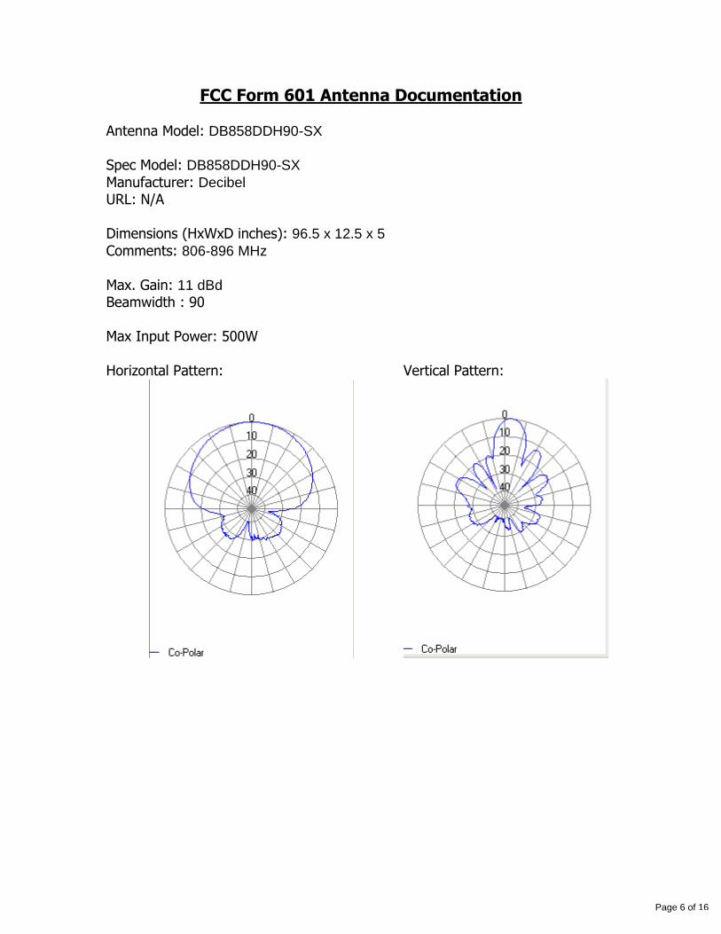
4. DB858DDH90-SX
FCC Form 601 Antenna Documentation Antenna Model: DB858DDH90-SX Spec Model: DB858DDH90-SX
Manufacturer: Decibel URL: N/A Dimensions (HxWxD inches): 96.5 x 12.5 x 5
Comments: 806-896 MHz Max. Gain: 11 dBd Beamwidth : 90 Max Input Power: 500W Horizontal Pattern: Vertical Pattern:
Page 6 of 16

5. DBXLH-6565C-VTM DBXLH-6565C-VTM±45° Dual Band Panel Antenna
Each antenna is independently capable of field adjustable electrical down tilt
Fully compatible with Andrew TELETILT® remote control antenna system.
Interlaced dipole technology providing for attractive, low wind load mechanical package
Provides two independent dual pol antennas under one radome
ELECTRICAL
Frequency (MHz) : 824 - 896 870 - 960 1710 - 1880 1850 - 1990 1920 - 2180
Polarization : ±45° ±45° ±45° ±45° ±45°
Gain (dBd/dBi) : 14.6/16.7 14.9/17 15.7/17.8 16.1/18.2 16.2/18.3
Azimuth BW (Deg.): 68 65 65 63 62
Elevation BW (Deg.): 8 7.5 5 4.7 4.4
Beam Tilt (Deg.): 0-8 0-8 0-6 0-6 0-6
USLS* (dB) : >15 >15 >15 >15 >15
Front-To-Back Ratio* (dB) : 26 26 30 30 25
Isolation (dB) : >30 >30 >30 >30 >30
VSWR : <1.5:1 <1.5:1 <1.5:1 <1.5:1 <1.5:1
PIM3 @ 2 x 20w (dBc) : -150 -150 -150 -150 -150
Max. Input Power (Watts) : 250 250 250 250 250
Impedance (Ohms) : 50 50 50 50 50
Lightning Protection : DC Ground DC Ground DC Ground DC Ground DC Ground
Notes: Same as ADFD0920-6565C-XDM. At maximum tilt angles, gain maybe slightly reduced.
DBXLH-6565C-R1MFactory Installed, ATM100 Series:
DBXLH-6565C-VTMField Installed:
Weight : 21.7 kg (48 lb)
Dimensions (LxWxD) : 2,576 x 267 x 132 mm(101.4 x 10.5 x 5.2 in)
Max. Wind Area : 0.35 m² (3.8 ft² )
Max. Wind Load (@ 100 mph) : 960.7 N (216 lbf)
Max. Wind Speed : 201 km/h (125 mph)Hardware Material : Galvanized Steel
Connector Type : 7-16 DIN - Female(4, Bottom)
Color : Off White
Standard Mounting Hardware : 600899A-2
MECHANICAL
RET Ordering Information
DBXLH-6565C-R2MFactory Installed, ATM200 Series:
Fax: 214.631.4706
Toll Free Tel: 1.800.676.5342
Fax: 1.800.229.4706
www.andrew.com
Andrew Corporation
2601 Telecom Parkway
Richardson, Texas U.S.A 75082-3521
Tel: 214.631.0310 [email protected]
6/14/2005
* - Indicates Typical
Information correct at date of issue but may be subject to change without notice. Page 7 of 16
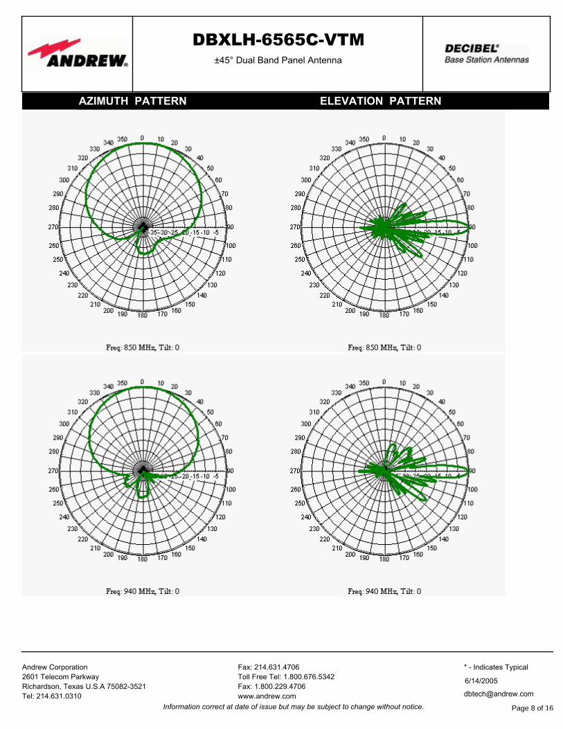
DBXLH-6565C-VTM±45° Dual Band Panel Antenna
AZIMUTH PATTERN ELEVATION PATTERN
Fax: 214.631.4706
Toll Free Tel: 1.800.676.5342
Fax: 1.800.229.4706
www.andrew.com
Andrew Corporation
2601 Telecom Parkway
Richardson, Texas U.S.A 75082-3521
Tel: 214.631.0310 [email protected]
6/14/2005
* - Indicates Typical
Information correct at date of issue but may be subject to change without notice. Page 8 of 16
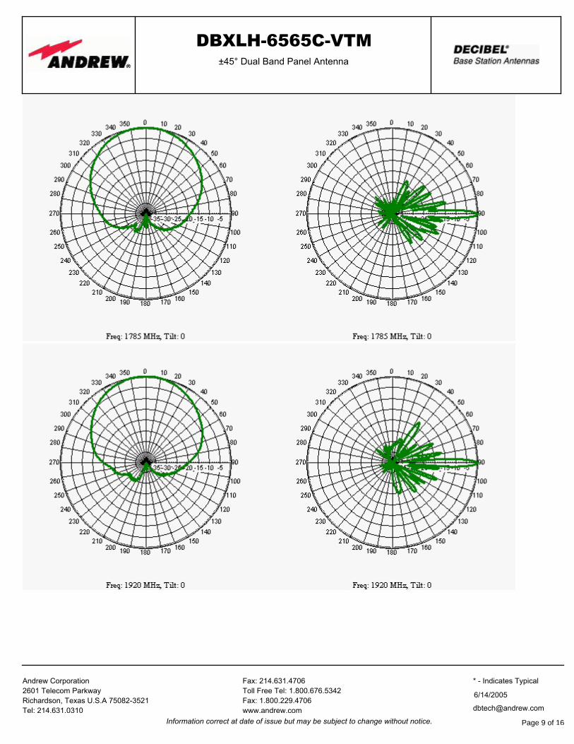
DBXLH-6565C-VTM±45° Dual Band Panel Antenna
Fax: 214.631.4706
Toll Free Tel: 1.800.676.5342
Fax: 1.800.229.4706
www.andrew.com
Andrew Corporation
2601 Telecom Parkway
Richardson, Texas U.S.A 75082-3521
Tel: 214.631.0310 [email protected]
6/14/2005
* - Indicates Typical
Information correct at date of issue but may be subject to change without notice. Page 9 of 16
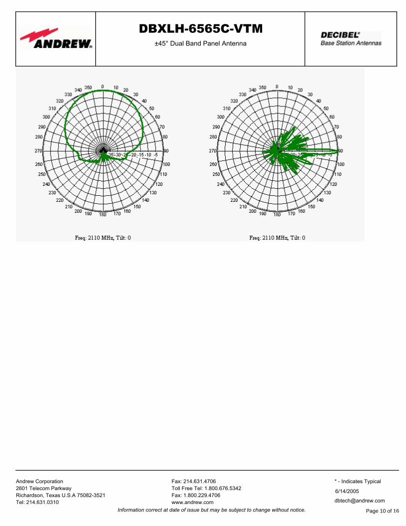
DBXLH-6565C-VTM±45° Dual Band Panel Antenna
Fax: 214.631.4706
Toll Free Tel: 1.800.676.5342
Fax: 1.800.229.4706
www.andrew.com
Andrew Corporation
2601 Telecom Parkway
Richardson, Texas U.S.A 75082-3521
Tel: 214.631.0310 [email protected]
6/14/2005
* - Indicates Typical
Information correct at date of issue but may be subject to change without notice. Page 10 of 16

6. DBXLH-9090A-VTM DBXLH-9090A-VTM±45° Dual Band Panel Antenna
Each antenna is independently capable of field adjustable electrical down tilt
Fully compatible with Andrew Teletilt® remote control antenna system
Patented split dipole technology
Provides two independent dual pol antennas under one radome
ELECTRICAL
Frequency (MHz) : 824 - 896 1850 - 1990 1920 - 2180
Polarization : ±45° ±45° ±45°
Gain (dBd/dBi) : 11.2/13.3 14.1/16.2 14.1/16.2
Azimuth BW (Deg.): 87 90 90
Elevation BW (Deg.): 16 6.8 6.5
Beam Tilt (Deg.): 0-16 0-8 0-8
USLS* (dB) : 15 15 15
Front-To-Back Ratio* (dB) : 26 30 30
Isolation (dB) : >28 >30 >30
VSWR : <1.4:1 <1.5:1 <1.5:1
PIM3 @ 2 x 20w (dBc) : -150 -150 -150
Max. Input Power (Watts) : 300 250 250
Impedance (Ohms) : 50 50 50
Lightning Protection : DC Ground DC Ground DC Ground
Notes: Same model as 732DG90VTEWB.
DBXLH-9090A-VTMField Installed:
Weight : 12.7 kg (28 lb)
Dimensions (LxWxD) : 1,306 x 391 x 127 mm(51.4 x 15.4 x 5 in)
Max. Wind Area : 0.24 m² (2.6 ft² )
Max. Wind Load (@ 100 mph) : 653.8 N (147 lbf)
Max. Wind Speed : 201 km/h (125 mph)Hardware Material : Galvanized Steel
Connector Type : 7-16 DIN - Female(4, Bottom)
Color : Light Gray
Standard Mounting Hardware : DB380
Standard Downtilt Mounting Hardware : DB5083
MECHANICAL
RET Ordering Information
DBXLH-9090A-R2MFactory Installed, ATM200 Series:
Fax: 214.631.4706
Toll Free Tel: 1.800.676.5342
Fax: 1.800.229.4706
www.andrew.com
Andrew Corporation
2601 Telecom Parkway
Richardson, Texas U.S.A 75082-3521
Tel: 214.631.0310 [email protected]
7/9/2006
* - Indicates Typical
Information correct at date of issue but may be subject to change without notice. Page 11 of 16

DBXLH-9090A-VTM±45° Dual Band Panel Antenna
AZIMUTH PATTERN ELEVATION PATTERN
Fax: 214.631.4706
Toll Free Tel: 1.800.676.5342
Fax: 1.800.229.4706
www.andrew.com
Andrew Corporation
2601 Telecom Parkway
Richardson, Texas U.S.A 75082-3521
Tel: 214.631.0310 [email protected]
7/9/2006
* - Indicates Typical
Information correct at date of issue but may be subject to change without notice. Page 12 of 16
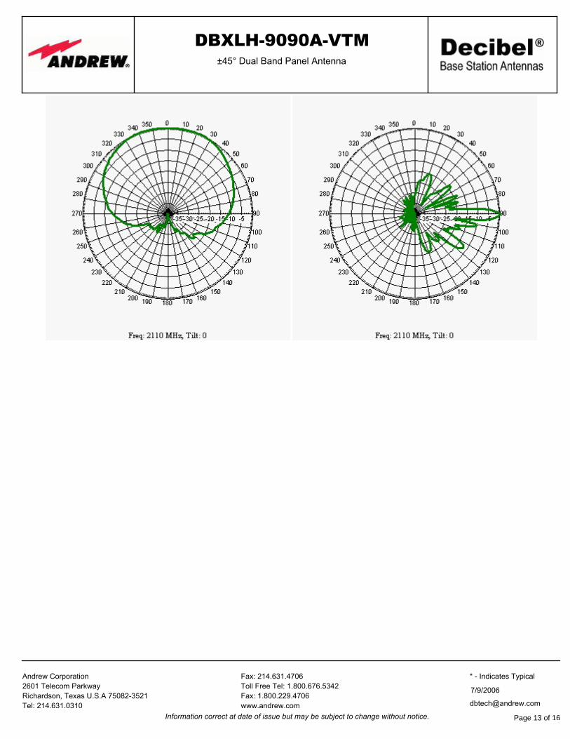
DBXLH-9090A-VTM±45° Dual Band Panel Antenna
Fax: 214.631.4706
Toll Free Tel: 1.800.676.5342
Fax: 1.800.229.4706
www.andrew.com
Andrew Corporation
2601 Telecom Parkway
Richardson, Texas U.S.A 75082-3521
Tel: 214.631.0310 [email protected]
7/9/2006
* - Indicates Typical
Information correct at date of issue but may be subject to change without notice. Page 13 of 16

7. DBXLH-9090C-VTM
DualPol® Dual Band Antenna, 824–960 MHz and 1710–2180 MHz, 90° horizontal beamwidth, RET compatible variable electrical tilt
DBXLH-9090C-VTM
l Two DualPol® antennas under one radome
l Patented dipole technology
l Each antenna is independently capable of field adjustable electrical tilt
l Fully compatible with Andrew remote electrical tilt system
CHARACTERISTICS
General Specif ications Antenna Type DualPol® dual band
Brand DualPol® | Teletilt®
Operating Frequency Band 1710 – 2180 MHz | 824 – 960 MHz
Electrical SpecificationsFrequency Band, MHz 824–896 870–960 1710–1880 1850–1990 1920–2180Beamwidth, Horizontal, degrees 87 87 90 90 90Gain, dBd 13.8 14.0 15.5 15.7 15.7Gain, dBi 15.9 16.1 17.6 17.8 17.8Beamwidth, Vertical, degrees 8.0 7.0 4.5 4.3 4.0Beam Tilt, degrees 0–8 0–8 0–5 0–5 0–5Upper Sidelobe Suppression (USLS), typical, dB 15 15 15 15 15FronttoBack Ratio at 180°, dB 30 30 35 35 35Isolation, dB 30 30 30 30 30VSWR | Return Loss, db 1.4:1 | 15.6 1.5:1 | 14.0 1.5:1 | 14.0 1.5:1 | 14.0 1.5:1 | 14.0Intermodulation Products, 3rd Order, 2 x 20 W, dBc 150 150 150 150 150Input Power, maximum, watts 300 300 250 250 250Polarization ±45° ±45° ±45° ±45° ±45°Impedance, ohms 50 50 50 50 50Lightning Protection dc Ground dc Ground dc Ground dc Ground dc Ground
Product Specifications
©2009 CommScope, Inc. All rights reserved.All trademarks identified by ® or ™ are registered trademarks or trademarks, respectively, of CommScope. All specifications are subject to change. See www.commscope.com for the most current information.
page 1 of 33/26/2009Page 14 of 16
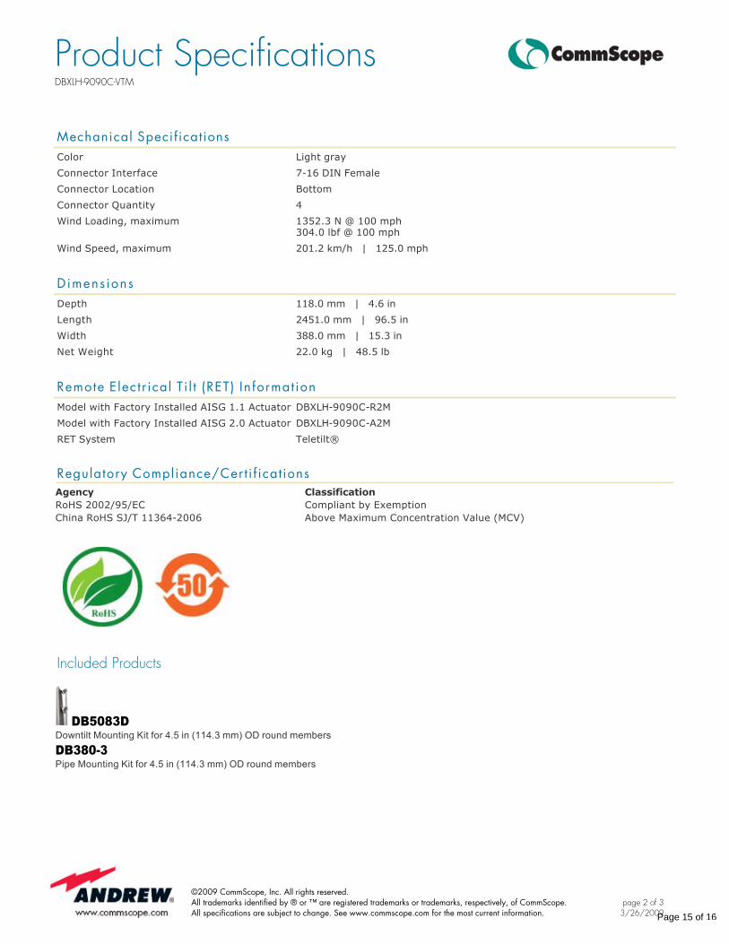
Mechanical Specif ications Color Light gray
Connector Interface 716 DIN Female
Connector Location Bottom
Connector Quantity 4
Wind Loading, maximum 1352.3 N @ 100 mph304.0 lbf @ 100 mph
Wind Speed, maximum 201.2 km/h | 125.0 mph
Dimens ions Depth 118.0 mm | 4.6 in
Length 2451.0 mm | 96.5 in
Width 388.0 mm | 15.3 in
Net Weight 22.0 kg | 48.5 lb
Remote E lec t r ical T i l t (RET) In format ion Model with Factory Installed AISG 1.1 Actuator DBXLH9090CR2M
Model with Factory Installed AISG 2.0 Actuator DBXLH9090CA2M
RET System Teletilt®
Regulatory Compliance/Cert i f icat ionsAgency ClassificationRoHS 2002/95/EC Compliant by ExemptionChina RoHS SJ/T 113642006 Above Maximum Concentration Value (MCV)
Included Products
DB5083DDowntilt Mounting Kit for 4.5 in (114.3 mm) OD round members
DB3803 Pipe Mounting Kit for 4.5 in (114.3 mm) OD round members
Product SpecificationsDBXLH-9090C-VTM
©2009 CommScope, Inc. All rights reserved.All trademarks identified by ® or ™ are registered trademarks or trademarks, respectively, of CommScope. All specifications are subject to change. See www.commscope.com for the most current information.
page 2 of 33/26/2009Page 15 of 16
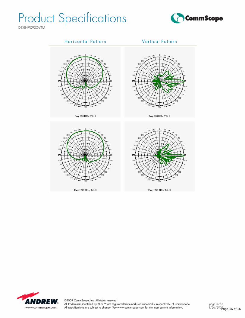
Hor izon ta l Pa t te rn Ver t ica l Pa t tern
Product SpecificationsDBXLH-9090C-VTM
©2009 CommScope, Inc. All rights reserved.All trademarks identified by ® or ™ are registered trademarks or trademarks, respectively, of CommScope. All specifications are subject to change. See www.commscope.com for the most current information.
page 3 of 33/26/2009Page 16 of 16