maintenance of substation1 - electrical engineering portal · maintenance of substation chapter 1...
TRANSCRIPT

1
Maintenance of Substation Chapter 1
GENERAL PHILOSOPHY
1.0 - INTRODUCTION
1.1 In today's competitive market scenario power utilities are under tremendous
pressure to cut down their maintenance costs as they form a significant portion of
the operation costs. This has led the utilities to adopt condition-based maintenance
of the equipments rather than usual preventive maintenance being carried out at a
fixed interval of time. Maintenance intervals are normally fixed on the basis of type
of equipment and sometimes on the equipment history. However, tests or
measurements are also carried out to assess the condition of the equipment.
2.0 TYPES OF MAINTENANCE
Different types of maintenance being done on equipment are:
i) Breakdown maintenance ii) Preventive maintenance iii) Condition based monitoring iv) Reliability centered maintenance
i) Breakdown Maintenance
As the name implies the maintenance is carried out when the equipment fails. This
type of maintenance may be appropriate for low value items. However for costly
substation equipments, it is not desirable to wait till the breakdown of the
equipment, as this cost more to the utility as well as the availability and reliability of
power gets affected. The revenue loss due to non-availability of the system shall be
much more than the cost of the failed equipment. Therefore identifying the defect
before failure, is more appropriate to plan repair / replacement.
ii) Preventive Maintenance
The preventive maintenance of equipment is being mostly adopted by almost all the
utilities. In this type of maintenance, the equipments are inspected at a pre-
determined period. The frequency determined based on the past experience and also
guidance from the manufacturer of the equipment. This type of maintenance would
require specific period of shut-down. Maintenance procedure, periodicity of
maintenance and formats for maintaining records for various types of sub-station
equipments have been discussed separately in detail in a separate section.

2
iii) Condition Based Monitoring
This type of maintenance technique is adopted to assess the condition of the
equipment. The condition of the equipment is assessed based on different condition
monitoring tests. Some of the tests are done on on-line and some are done on off-
line. However, this type of maintenance would need sophisticated testing equipments
and skills for analyzing the test results.
iv) Reliability Centered Maintenance
This is the recent technique being adopted in maintenance philosophy. The basic
objectives of reliability-centered maintenance are:
- Maintenance should keep the equipment at desired
level of performance
- Optimizing / minimizing the maintenance / shutdown
period so as to enhance the availability of the
equipment.
- Deferring / avoiding the replacement of components
and major/minor over-hauls till it is absolutely
necessary.
Reliability centered maintenance policy is based on the life cycle cost concept and
the decision for replacement of the equipment is taken based on techno-economic
considerations. From the view point of RCM our objective should be to devise a
system, which does not need periodic maintenance and at the same time predict in
advance possible failures/problems of the equipment. To meet this aim we have to
develop equipment which require either no or very little maintenance and on the
other hand the concept of condition based maintenance should be implemented.
Realization of this objective will result in enhancing availability, reliability and
reduction in manpower for maintenance purposes.
3.0 FAILURES OF EQUIPMENTS
3.1 Failure of any equipment should taken up seriously. Detailed analysis of each
failure should be done which will help in reduction/stopping of repeated failures of
same nature. It is general experience that in spite of doing regular maintenance,
failure of the equipment can't be totally eliminated. Number of EHV equipment
failures have been reported practically by all the utilities and some of them have
been quite serious resulting in consequential damage to the adjoining equipment.
Circuit breakers operating on high pressure when they fail, they explode like a
bomb resulting in scattering of insulator pieces to a larger distance and damage to
the adjoining equipment. Similar situation have also been faced with the failure of

3
surge arrestors and current transformers. Some of the typical failures of equipment
and the remedial measures adopted have been discussed in a separate section.
4.0 NEED FOR CONDITION BASED ASSESSMENT OF EHV EQUIPEMNT
4.1 In the present competitive environment, all utilities are making efforts to reduce
the O&M expenditure. This puts lot of pressure on the utilities to minimize the
outage period due to failure of equipment. This necessitates adopting of condition
based monitoring as the Need of the Hour. This has necessitated all the power
utilities to introduce condition based monitoring for EHV class equipment so that
actual condition of the equipment and its residual life could determine. Modern
techniques are available for condition based monitoring and the concept of residual
life assessment is picking up worldwide.
Chapter 2
CAUSES OF FAILURES OF MAJOR SUB-STATION EQUIPMENTS
AND REMEDIAL MEASURES
1. INTRODUCTION
This section briefly describes about the probable causes of failure of major sub-
station equipment viz. Power Transformers, Reactors, Circuit Breaker, Instrument
Transformers, Surge Arrestors etc. and remedial measures taken to prevent such
failures.
2. POWER TRANSFORMERS
Power Transformers are vital links in the chain of components constituting a power
system, the failure of which affect the supply of electric power to the consumers.
Internationally, the transformers are found to be very reliable but in our country
the failure rates are quite high. Failure analysis quotes a host of reasons behind the
failure of power transformers. These may include abused operations inept
maintenance, substandard techniques adopted during manufacturing, testing and
commissioning, substandard input materials, inconsistency environment, design
deficiencies, abnormal operating conditions, over voltages, system short circuits etc.

4
The main causes of failures of transformers in service (CIGRE Survey) is given
below:
Cause % of cases
Design 36
Manufacturing problem
28
Material defects 13
Poor maintenance 5
Lightning surges 4
Short circuits 2
Components % of cases
Winding 29
Terminal 29
Tank and Di-electric fluid
13
Magnetic Circuit 11
Other accessories 5
However the main causes of failure as pertaining to our country are given below:
Table
Causes % Failures
Design defects 35.7
Manufacturing problems 28.6
Material defects 13.1
Transport or storage problems 1.2
In-correct maintenance 4.8
Abnormal overload Less than 1
Over-fluxing 1.2
Lightning 3.6
External short circuit 2.4
Loss of cooling 1.2
Unknown 7.1

5
However, The failures in power transformers can be broadly classified as:
• Weakness in specification, design / manufacturing deficiency • Installation / operation / maintenance deficiency • Adverse operating conditions • Aging
2.1 Weakness in specifications
Many a times, a customer specification is silent on the various aspects of site
conditions such as loading pattern, over fluxing, over voltage conditions, various
system parameters, environmental conditions. These are some of the aspects where
care has to be taken at the time of drafting of technical specifications.
2.2 Failure due to defective design
Some of the failures due to defective design are listed in the table given below.
Cause Effect Remedial Measures
Failure of yoke bolt in insulation
Causes local short circuit in the lamination resulting in intense local eddy currents
Insulated yoke bands preferred or yoke bolt insulation should be class ‘B’ insulation or higher.
High flux density in core
Causes large amount of force at time of switching and repeated switching damage winding insulation
Flux density should not exceed 1.9 Tesla at maximum operating voltage
Narrow oil duct in winding
Results in improper cooling and damages insulation
Adequate duct from point of effective cooling
Improper transpositions
Results in more loss and more heating Adjust the transpositions so that all conductors should have equal reactance
Inadequate clearance between phases
May result in short circuit Provide adequate clearance as per the voltage class
Clamping ring not properly designed
May fail during short circuit condition Thickness of clamping ring should be designed such as to withstand short circuit forces
Insufficient bracing of leads
May fail during short circuit condition Strong supports are required for bracing of leads
Radiators not properly designed
Result in improper cooling causing higher temperature for oil/windings
Proper calculation of radiators is necessary

6
2.3 Failures due to manufacturing deficiencies
Transformer manufacturing is more a craftsmanship rather than the machine
work. The reliability of the transformer depends on the quality of raw materials and
the workmanship. There are certain steps to be taken at manufacturing stage so that
apparently minus slips-ups at that stage do not get amplified in major defects later
on in service. Some of the failures due to manufacturing deficiencies are listed in
Table given below.
Cause Effect Remedial Measure
Loose winding and improper sizing
Result in interturn or interdisc short circuit
Proper sizing for keeping winding under clamping condition
Burrs on lamination Result in local short circuit and result in heating
Burr free condition to be ensured by good manufacturing facility
Burrs on spacers and blocks
Result in damaging conductor insulation
Burr free condition to be ensured by good manufacturing facility
Bad brazed joints Damage the conductor insulation and winding may fail
Adopt good brazing procedures
Metallic parts left over during manufacture
May cause partial discharge Better house keeping to ensured
Insulation surface contamination
Results in insulation failure Cleanliness to be ensured
All metal components not earthed
Partial discharge may start and oil quality may get affected
All metal components are to be properly earthed and this is to be added in check-list
Bad and porous welding of transformer tank
Result in oil leakage Surface cleanliness to be ensured and adopt good welding procedures
Improper drying process Winding and insulation are not fully stabilized due to moisture leading to failure
Extensive drying and oil impregnation process should be strictly followed as per voltage class
2.4 Failures due to defective materials
The quality of material used also reflects on the life of the transformers. A rigid
control of quality at all the successive stages of manufacture right from raw
material to finished product will avoid the failure in transformers. Some of the
failures due to defective material is listed in Table given below:

7
Cause Effect Remedial measure
Sharp edges in copper conductors
Produce partial discharge and damage the conductor insulation
The surface finish should be smooth
Improper conductor insulation
Deteriorate under influence of high voltage stress and damage insulation
Check the incoming conductor insulation and also no. of layers for conductor covering
Poor oil quality Insulation failure Maintain BDV & PPM as per manufacturer’s recommendations
Particles in oil held in suspension
Temporary breakdown Maintain oil cleanliness
Bare copper for connection Formation of oxidation and sludges
Provide enamel coating or paper covering on bare copper
Defective accessories
OLTC
1. Bushings 2. Buchholz relay 3. Protective equipment
Results in transformer failure These accessories to be procured from well established supplier in view of high service reliability
2.5 Adverse operating conditions
The life of a transformer is normally dependent on the life of insulation. During the
normal operation of the transformer, the ageing process is also at normal rate. The
rate of ageing is related to temperature, moisture content and duration of loading
conditions. At temperatures more than 140ºC, the gas bubbles are formed as
a result of insulation deterioration. These bubbles are of potential danger in the
vicinity of high voltage stress zone. This can initiate electrical damage leading to
breakdown.
Life expectancy of transformer will get diminished through inadequate protection
while operating in the abnormal conditions such as:
1. Sustained overload conditions 2. Switching surges 3. Lightning surges 4. Transferred surges

8
2.6 Improper maintenance practices
Poor/inadequate maintenance in the areas of oil leakage, oil quality, critical
accessories such as tapchangers, bushings, protective instruments etc. will cause
trouble in transformer. In addition to this, there are various trouble-shooting
problems encountered in the field, such as moisture, oxidation, solid contamination,
gas bubbles, overcurrent, overvoltage (transient or dynamic), over temperatures,
short circuit (mechanical forces) etc., for which sufficient care should be taken to
safeguard the transformer. Preventive maintenance is strongly recommended to
improve the reliability of transformer.
Some of the reported failures for transformers have been attributed due to either of
the following causes:
1. Failure of the winding insulation due to short circuit stresses 2. Failure of winding insulation due to surge voltages and transient surges 3. Failure of magnetic circuit 4. Failure of OLTC 5. Failure of bushings and other accessories 6. Failure due to poor insulation and poor cooling arrangements
Some of these failures are briefly described below:
2.7 Failure of HV, LV and Tertiary Winding due to Short Circuit and Surge
Voltages
Safety margin of transformer with reference to short circuit withstand capability
has been reduced widely. ISS stipulates a time of 2 seconds. The World Bank
Specifications recommends a time duration of 1 sec. On account of the graded time
discrimination provided on the protective relays, which are essentially over current
and earth fault relays. Bus faults are cleared after a time delay and many of the
transformers have been found failing for bus faults or a nearby fault on feeder
converting into a bus fault due to failure of feeder breaker to trip.
The tertiary winding provided on the power transformer are not adequately related
to provide insulation to withstand surge voltages as also not rated for adequate
short circuit stresses. Tertiary winding inter-turn insulation failures have been
found to be due to transferred surges also. Based on investigations of failure of
tertiary winding CBIP has already brought out research paper providing guidelines
for protections to be provided on loaded tertiary. As per CBIP manual on
transformers, provision of tertiary winding has now been deleted upto 100 MVA, 3
phase 3 limbed core type construction. Special precaution for protection of tertiary
is necessary particularly in case of capcitive/reactive loading. Frequency of
switching on/off of capacitor/reactor, distance of source from the transformer,
design and location of gapless arresters are some of the important factors which
9
have to be considered before loading of the tertiary. Failure of tertiary windings
generally have been experienced because of:
• Overstressing and inadequate cooling • Improper implementation of protective schemes • Frequent switching ON/OFF of capacitive reactive load • Improper short circuit withstand capability
CBIP’s technical report on causes of failure of tertiary windings and BHEL’s
recommendations for protection of tertiary winding (Journal Vol. 3 No.1 of 1978)
provides required guidelines on the subject.
The clamping arrangement provided on the transformer to contain the short circuit
forces were not found to be adequate. In some cases, the interphase and phase to
ground clearance of the leads were found to be less which resulted into flash over
and damage of insulation due to vibration and displacement under short circuit
current. Damage has taken place in some cases due to failure of insulating
components eg., insulating cylinders, supports, permalli wood etc. The failure of
joints have also been reported while handling short circuit current. A few cases of
failure of transformer on lighting impulse have been reported inspite of protection
provided by lightning arrestors.
Failure of the transformers has been reported on switching surges. The transformer
failed, when it was being energized after a supply failure form upper substation on
tripping of transformer on external faults. Operation of differential and bucholz
protection took place tripping the transformer breaker and isolating the
transformer. In a few cases, the transformers have failed where Polarization Index
(P1) of winding insulation had deteriorated to 1.1 or less in spite of moisture content
in transformer oil remaining within limit up to 35 PPM & BDV 50 KV.
Deterioration of P1 Index on sustained temperature on load needs to be specified
and examined. In one or two cases, the substation earth resistance was found to be
higher. This resulted into high voltages to be impressed at neutral end of the
winding during phase to ground short circuit on feeder/bus. This caused failure of
interturn insulation at neutral end.
2.8 Failure of magnetic circuits
There have been failure transformer due to overheating of core and core burning,
failure of core insulation and core assembly getting used, slipping of stampings and
coming in contact with tank bottom. To overcome the above problems separate
provision for core earthing and core fixture earthing through bushings provided by
transformer is being resorted to. This facilitates monitoring of core leakage current,
if any, and in ascertaining that core is not getting multiple earth and also healthiness
of core board insulation.
2.9 Failure of on-load tap changers (OLTC)

10
On –load tap changers are the second largest reason for trouble in power
transformers after short circuit. The defects in OLTC are of the following type:
1. Burning of transition resistance 2. Burning and damage of rollers and fixed contacts 3. Misalignment of the tap changer assembly 4. Error in time sequence operation 5. Defect in tap changing driving gear i.e. malsoperation of limit switches and
step-by-step contractors etc.
Some of the common problems noticed in the OLTC compartment, selector/diverter
switch are:
• It appears that the manufacturer does not exercise proper care in selecting
current rating of the OLTC. Factors for efficiency of operation and over
loading capability of transformer have to be accounted for to arrive at design
current rating. The selected current rating normally should be one step
higher than the calculated value. It would be advisable if purchaser’s
technical specifications do not leave this option to the manufacturer and
current/voltage ratings are specifically stipulated.
• Quality and rating of transition resistors have been one of the main sources
of problem in OLTC. Repeated incidences of burning of transition resistors
are an area, which calls for serious attention from OLTC manufactures. • Open circuiting or burning of transition resistors leading to selector switch
spark over and fire in tap switch resulted into bursting of pressure relief
diaphragm in MR type tap changer. • Failure of limit switch to stop operation at extreme position of tap changer
have led to severe arcing, pressure build-up and bursting of OLTC
compartment. • In sealed breathing transformers, defective oil seals and ‘O’ rings have led to
transfer of oil under pressure from main takn to diverter switch and leakages
through silicagel breather resulting into fall in main tank oil level which is an
operational hazard. • Crack in barrier board has also been a cause of failure owing to non-
equalization of pressure between main tank and OLTC, while applying
vacuum at the time of first erection and drying out.
2.10 Failure of bushings
Condenser type bushings are sent with tip portion sealed and covered by porcelain
rain shade. The bottom condenser portion is sent covered with wax coated cotton
tape. In some of the transformers these transit tapes were e not removed while
hoisting the bushings on the transformer. Over a period of service, the wax melted
on contact with hot oil inside the tank and the cotton tape opened out and caused
discharge inside the tank. It is better to dispatch bushings from works with bottom

11
portion sealed in oil filled tanks to be removed at site at the time of erection to avoid
moisture ingress.
2.11 Suggestions to reduce failures
From the foregoing discussion reasons for transformer failure could be attributed to
various causes. Some of the possible corrective steps are enlisted herein, to reduce
such casualty.
2.12 Improved design and manufacturing practice
By adopting CAD and better shop floor management, more reliable units could be
manufactured to eliminate:
• Poor short circuit withstand capability • Manufacturing defects including cooling system • Problems associated with bushings • OLTC including selector/diverter switch • Tertiary winding failure wherever provided
2.13 Improved testing method
Transformer should be simulated to actual service condition first by sequential
testing and then passing necessary current, which could result, into temperature
rise. Thereafter conduction of all high voltage application tests could bring out
insulation weakness. Simulated short circuit test if necessary on scaled model and
measurement of magnetic balance and magnetization current could reveal
abnormality. Finally oil parameter could be recorded after completion of all the
tests and compared with initial values.
2.14 Erection at site
By adopting strict pre-commissioning test and checks possible erection mistakes and
omissions could be avoided.
2.15 Problems external to transformer
Load management
By adopting efficient load frequency management systems could be better-
controlled avoiding damages and transformer failure due to
• Overloading • Over fluxing and over voltage • Hot joints and spark over • Frequent feeder tripping due to reflected faults

12
After every tripping of transformer whether manually or through protective relay,
before recharging the tap switch should be manually operated to bring the same to
No.1 position. After loading, the transformer tap could be changed to suit bus
voltage requirement.
Failure of switchgear and battery
This could be avoided by periodic testing and using proper duty switch-gear and
battery.
2.16 Sub-station layout
Layout
Whenever single phase units are installed it is essential to provide partition walls of
adequate heights and strength to prevent collapse. This will minimize chances of fire
extending to the other units.
Soak pit and drain pit
Provision may be made for the necessary soak pit and drain pit in the substation
layout.
3. FAILURE OF CIRCUIT BARKERS
A circuit breaker is considered to have failed, when the breaker fails to operates
after a command is given or unable to interrupt the arc or withstand a system
voltage. CB failures have resulted in blasting of one or more of the following
components:
1. interrupting chambers 2. pre-insertion resistor chambers 3. grading capacitors 4. support column including tie/operating rods
Besides the above, the failure of breakers could also be attributed due to following
reasons:
• Mechanical failure of operating lever • Shearing off of the locking pin of pull rod • Grading capacitor failure • Embedding of PIR fixed contact assembly into the moving contact housing
due to loosening of grub screw. • Dielectric failure inside interrupting chamber due to high moisture in SF6
gas.

13
• Insulation failure (live to earth) due to accumulation of moisture on tie rod
during storage. • Failure of mechanical coupling between tie rod and operating mechanism. • Failure of actuating valves in operating mechanism. • Failure due to foreign particles (eye pieces) inside interrupter. • Failure due to high transient recovery voltage (TRV). In case of circuit
breakers switching HVDC filter banks, the normal duty of CB is opening, the
resulting TRV can be severely distorted due to presence of filters and can
severely depart from the 1 – cos wave shape which may cause high TRV and
leading to internal breakdown in grading capacitor or interrupter. • Dielectric failure in Air Blast CBs. • Others.
3.1 Preventive Measures for Avoiding CB Failures
The type of failures that have taken place reveals that there is urgent need to
improve manufacturing quality of various components besides, if effective condition
monitoring checks are also carried out, failures could be identified at the incipient
stage and corrective actions can be taken accordingly. However following areas are
suggested for preventive measures.
Design/technical specification modification
The modifications suggested in the technical specifications are as follows:
• ‘Mechanical Close Interlock’ wherever provided should be identical for CB
with PIR or without PIR in order to avoid mixing of operating drives during
erection and during O&M. • Interconnecting piping between different poles of CBs have been removed
and individual pole density monitor has been provided. • SF6 gas cylinder to be tested for dew point, air content etc. as per IEC-376
and test certificate alone will not be sufficient. • Minimum time for PIR contacts open prior to opening of minimum contacts
should be 5 msec. • Routine tests shall include measurement of dynamic contact resistance
measurement and tan delta measurement of grading capacitor in order to
have base values. • Upto 200 kilometers transmission line length pre insertion resistance need
not be provided with the barkers. This is based on study carried by a leading
power utility.
Stringent quality checks during manufacturing
To avoid failures of CBs due to manufacturing defects, it is required to introduce a
stringent quality checks in the standard manufacturing plans. Following quality
checks are suggested:

14
• All operating levers to be tested for ultrasonic and radiography. • PIR contact gap adjustment during assembly was made as 100% CIP. • Mechanical endurance test for 10000 operations conducted on 400 kV CBs. • Dynamic contact resistance measurement and tan delta measurement of
grading capacitor made as part of routine tests. • Tensile test on operating levers made as customer inspection point • Microstructure analysis of operating levers • HV test on operating rod made as 100% customer inspection point (CIP) • Testing SF6 gas foe dew point measurement before supply • Modification of PIR Pull rod (PTFE) having better tensile strength. • Improvement in machining of contact surface of pilot valves • Nitrogen accumulators • Gaskets: Gaskets can sometime fail to do their job of forming a gas or liquid
seal but care must be exercised against excessive or unevenly applied
greasing of the gasket. Positioning of the gasket is important. • SF6 gas tightness: The possible origins and causes are various for SF6 gas
leakage, for example: 1. Corrosion near a seal can be avoided by controlling moisture content
in SF6 gas. 2. Damage of a seal 3. Impurity under a seal 4. Porosity of metal component (casting, brazing).
Introduction of state-of-the-art condition monitoring checks during service
Following condition assessment techniques may be adopted.
1. Dynamic contact resistance measurement 2. Dew point measurement of SF6 gas. 3. Contact travel measurement 4. Operating timings 5. Tan delta measurement of grading capacitors 6. Trip/close coil currents measurement 7. SF6 gas/hydraulic oil/air leakage monitoring.
4. FAILURES OF INSTRUMENT TRANSFORMERS
4.1 Failure of CTs
Preliminary failure analyses of failed CTs have revealed that most of the CTs have
failed due to pre-mature ageing of primary insulation. Besides, other probable
reasons of failure have been attributed to high system parameters i.e. voltage and
frequency, switching over voltages, lighting over voltages. To minimize the failure of
CTs following tests/checks are suggested for carrying out at site.

15
• Measurement of tangent delta and capacitance • Recovery voltage measurement • DGA monitoring • Furan analysis
4.2 Failure of CVTs
Preliminary failure analysis of failed CVTs have revealed that main reasons of CVT
failures are:
• High value of tan delta • Secondary voltage abnormal • High value of capacitance • Oil leakage • Humming sound
Besides the above following problems were also observed in one make of CVT:
• Snapping of bellow connection • Burning of damping resistor • Burning/failure of lightning arrestor • Failures of capacitor stacks • Blackening of insulating oil in EMU tank
The only remedial measures suggested to avoid failures is to do the proper condition
monitoring checks of CVTs at site.
5. FAILURES OF SURGE ARRESTORS
Analysis of failure of surge arrestors have revealed failures mostly due to premature
degradation of ZnO discs. To minimize the failure of surge arrestors it is suggested
that surge arrestors are monitored online for presence of third harmonic resistive
current in the leakage current flowing through surge arrestors. Leakage current
upto 500 micro Amp is generally considered within acceptable limits.

16
Chapter 3
Typical Limiting Values and Maintenance Schedules
Sl. No. Equipment / test data Permissible limits Reference 1. Transformer/Reactor (A) Transformer oil
a) BDV
- At the time of first charging 600 kV (Gap – 2.5 mm) – Minimum IS – 1866
- During O&M 50 kV (Gap – 2.5 mm) – Minimum IS – 1866
b) Moisture content
- At the time of first charging 15 PPM (Max.) IS – 1866
- During O&M 25 PPM (Max.) -do-
c) Resistivity at 90 degree C 0.1-1012 Ohm-CM (Min.) -do-
d) Acidity 0.2 mg KOH/gm (Max.)
e) IFT at 27 degree C 0.018 N/M (Min.) IS – 1866
f) Tan delta at 90 degree C 0.20 (Max.) -do-
g) Glash point 126 Deg. C (Min.) -do-
B) Vibration level for reactors 200 Microns (Peak to Peak)
60 Microns (Average) C) Tan delta for bushing at 20 Deg.
C 0.007* IEC – 137
D) Capacitance for bushing + 5% variation E) IR value for winding 1000 M-Ohm By 5.0/10.0 kV Megger F) Tan delta for windings at 20
Deg. C 0.007* IEEE/C57.12.90.1980
G) Contact resistance of bushing terminal connectors
10 M. Ohm / Connector NGC.UK Recommendations
H) Turret Neutral CT ratio erros + 39 IS – 2705 2. Circuit Breakers A) Dew point of SF6 gas Dew point values as per Annexure – II B) Dew point of operating air -45 Deg. C at ATM. Pressure C) CB Operating timings 400 kV 220 kV
a) Closing time (Max.) 150 MS 200 MS
b) Trip time (Max.) 25 MS 35 MS
c) Close/trip time, Pole discrepancy
– Phase to Phase (Max.) 3.33 MS 3.33 MS
- Break to break (Max.) of same phase
2.5 MS 2.5 MS

17
D)
PIR time
BHEL make 12-16 MS Manufacturers Recommendations
CGL make 8-12 MS
ABB make 8-12 MS -do-
NGEF make 8-12 MS
M&G make 8-12 MS
TELK make 8-12 MS
ABB make (HVDC) 8-12 MS E) PIR opening time prior to
opening of main contacts (ABB, CGL, NGEF make CBs)
5 MS (Min.) at rated pressure
F) Pir and main contacts overlap time [BHEL, M&G, ABB (imported) make CBs]
5 MS (Min.) – at rated pressure
G) Tan delta of grading capacitors 0.007 at 20 Deg. C H) Capacitance of grading
capacitors Within + 10% / - 5% of the rated value IEC 358
I) Contact resistance of CB 150 M. Ohm J) Contact resistance of CB
terminal connector 10 M. Ohm per connector NGC, UK
recommendations K) IR value:
1. Phase – earth 1000 M Ohm (Min.) by 5.0 / 10.0 kV Megger
2. Across open contacts 1000 M Ohm (Min.) by 5.0/10.0 kV Megger
3. Control cables 50 M Ohm (Min.) by 0.5 kV Megger L) Pressure switch settings
- SF6 gas pressure switches Within + 0.1 Bar of set value
- Operating air pr. Switches Within + 0.1 Bar of set value
- Operating oil pr. Switches Within + 1.0 Bar of set value M) BDV of oil used for MoCB
- At the time of filling 40 kV at 2.5 mm Gap (Min.) Mfgs. Recommendation
- During O&M 20 kV at 2.5 mm Gap. (Min.) Mfgs. Recommendation
3. Current Transformers A) IR value
1. Primary – earth 1000 M – Ohm (Min.) by 5.0/10.0 kV Megger
2. Secondary – earth 50 M – Ohm (Min.) by 0.5 kV Megger
3. Control cables 50 M-Ohm (Min.) by 0.5 kV Megger

18
B) Tan delta value 0.007* at 20 Deg. C C) Terminal Connector 10 M-Ohm per connector NGC, UK
Recommendations D) CT ratio errors + 3% - Protection cores IS – 2705
+ 1% - Metering cores -do-
4. Capacitive Voltage Transformers A) Tan Delta 0.007* at 20 Deg. C B) Capacitance Within +10%/-5% of the rated value IEC – 358 C Contact resistance of terminal
connector 10 M-Ohm per connector NGC, UK
Recommendations D) IR Value
1. Primary – earth 1000 M – Ohm (Min.) by 5.0/10.0 kV Megger
2. Secondary – earth 50 M – Ohm (Min.) by 0.5 kV Megger
3. Control cables 50 M-Ohm (Min.) by 0.5 kV Megger E) EMU tank oil parameters
a) BDV (Min.) 30 kV (Gap. –2.5 mm) IS – 1866
b) Moisture content (Max.) 35 ppm -do-
c) Resistivity at 90 Deg. C 0.1 – 1012 Ohm. – CM -do-
d) Acidity 0.5 mg kOH /gm (Max.) -do-
e) IFT at 27 Deg. C 0.018 N/M (Min.) -do-
f) Tan delta at 90 Deg. C 1.0 Max. -do-
g) Flash point 125 Deg. C (Min.) -do-
F) CVT voltage ratio errors + 5% protection cores IEEE/C93.1.1990 + 0.5% metering cores IEC 186
Sl. No. Equipment / test data Permissible limits Reference
5. Isolators A) Contact resistance 300 M-Ohm. (Max.) B) Contact resistance of terminal
connector 10 M – Ohm per connector NGC, UK
Recommendations C) IR value
1. Phase – earth 1000 M – Ohm (Min.) by 5.0/10.0 kV Megger
2. Across open contacts 1000 M – Ohm (Min.) by 5.0/10.0 kV Megger
3. Control cables 50 M-Ohm (Min.) by 0.5 kV Megger 6. Surge Arrester A) Leakage current 500 M-Amp. (Resistive) Hitachi, Japan
Recom. B) IR value 1000 M-Ohm. (Min.)
19
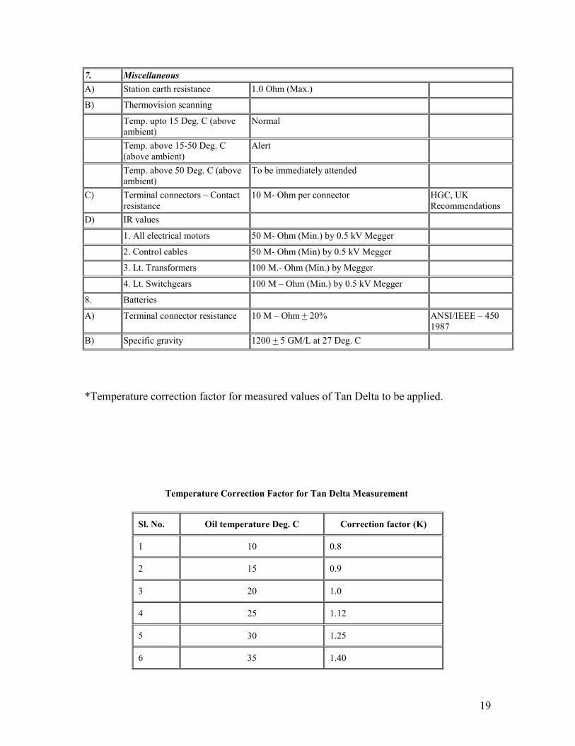
7. Miscellaneous A) Station earth resistance 1.0 Ohm (Max.) B) Thermovision scanning
Temp. upto 15 Deg. C (above ambient)
Normal
Temp. above 15-50 Deg. C (above ambient)
Alert
Temp. above 50 Deg. C (above ambient)
To be immediately attended
C) Terminal connectors – Contact resistance
10 M- Ohm per connector HGC, UK Recommendations
D) IR values
1. All electrical motors 50 M- Ohm (Min.) by 0.5 kV Megger
2. Control cables 50 M- Ohm (Min) by 0.5 kV Megger
3. Lt. Transformers 100 M.- Ohm (Min.) by Megger
4. Lt. Switchgears 100 M – Ohm (Min.) by 0.5 kV Megger 8. Batteries A) Terminal connector resistance 10 M – Ohm + 20% ANSI/IEEE – 450
1987 B) Specific gravity 1200 + 5 GM/L at 27 Deg. C
*Temperature correction factor for measured values of Tan Delta to be applied.
Temperature Correction Factor for Tan Delta Measurement
Sl. No. Oil temperature Deg. C Correction factor (K)
1 10 0.8
2 15 0.9
3 20 1.0
4 25 1.12
5 30 1.25
6 35 1.40

20
7 40 1.55
8 45 1.75
9 50 1.95
10 55 2.18
11 60 2.42
12 65 2.70
13 70 3.00
If Tan Delta of bushing/winding/CVT/CT is measured at oil temperature T Deg. C. Then Tan Delta at 20 Deg. C shall be as given below:
Tan Delta at 20 Deg. C = Tan Delta at Temp T Deg. C / Factor K.
Dew Point Limits for SF6 Gas in EHV Circuit Breakers
Sl. No. Make of CB Dew point at rated Pr. Deg. C
Corresponding dew point at Atmo. Pr.
Remarks
1. BHEL -15 -36 At the time of commissioning
-7 -29 During O&M
-5 -27 Critical
2. M&G -- -39 At the time of commissioning
-32 During O&M
3. CGL -15 -35 At the time of commissioning
-10 -31 During O&M
4. ABB -15 -35 At the time of commissioning
-5 -26 During O&M
5. NGEF -15 -36 At the time of commissioning
-7 -29 During O&M
-5 -27 Critical

21
Note: Dew point of SF6 gas varies with pressure at which measurement is carried out. So it is to be ensured that if measurement is done at pressure other than atmospheric pressure, it needs to be converted to the atmospheric pressure as given below.
Testing Sequence for Power Transformers
S.No Test AT
Manufactuer’s
Work
While
Commissioning During
Maintenance
1 Ratio Yes Yes Yes
2 Winding resistance measurement (at all taps)
Yes Yes Yes
3 Insulation resistance and Polarisation Index
Yes Yes Yes
4 Polarity, vector group Yes Yes ---
5 Separate source withstand voltage
Yes --- ---
6 Measurement of No. load losses
Yes Yes ---
7 Load losses and measurement of impedance (at all taps)
Yes Yes ---
8 Temperature rise test Yes Yes ---
9 Impulse withstand test Yes --- ---
10 Switching surge withstand test Yes --- ---
11 Induced voltage withstand and partial discharge measurement
Yes --- ---
12 Measurement of iron losses (after all type tests)
Yes Yes ---
13 Measurement of insulation resistance and polarization index
Yes Yes Yes
14 Measurement of capacitance and tan delta of windings
Yes Yes Yes

22
Check List for Transformer Assembly
1 The erection drawings and literature of the transformer is available at site
Yes/No
2 Checked and found all the component available at site as per drawing (there are no breakages and shortages)
Yes/No
3 Rinsed all the pipings, radiators, conservator etc. with 60 KV tested oil and blocked with dummy plates
Yes/No
4 Filtered the oil for 60 KV BD value and recorded in the erection register (with 22.5 mm gap on oil test kit)
Yes/No
5 Measured the insulation values of the HV, MV condenser type bushing (with a 5 KV megger) found more than 5000 M. ohms after removing coverings, wrappers etc.
Yes/No
6 Washed with hot oil (in case of other bushing of plain porcelain type)
Yes/No
7 Assembled the bushing, after fixing corona shield and removing links and bends in pull through leads, on the turret at proper incline
Yes/No
8 Complete assembly of HV, LV T&N bushing done correctly Yes/No
9 Completed all piping work consrvator explosion vent, equalisr pipes etc. as per the drawing and filled with oil, Buchholz relay checked (3º -7º incline)
Yes/No
10 Filled radiator after washing individually and ensuring removal of blanking plates and free movement of butterfly valves both top and bottom
Yes/No
11 Measured IR values with temperature after filling of oil and compared with the test values received from the supplier and recorded in register
Yes/No
12 For drying out of transformer Yes/No
a) Applied proper lagging around the transformer. Fire fighting equipments procured and kept at site
Yes/No
b) Filter machine cleaned and filled with the transformer oil Yes/No
c) Filter connected with outlet into the conservator and inlet from the bottom tank
Yes/No
d) Filter heaters, switched on and the filter temp. maintained less than 60 degree C and filter vacuum maintained of 755 mm of mercury
Yes/No

23
e)
Dehydration process for 7 days maintained oil temperature 60 degree C in the transformer (thermometer pockets filled with oil)
Yes/No
13 Filled the radiators with 60 KV BDV tested oil. Opened the bottom butterfly valves provided between main tank and the radiators after opening top air release valve to communicate with main tank
Yes/No
14 All gases released from different release points in order to ascending heights
Yes/No
15 HV, LV T Neutral earthing provided Yes/No
16 Petroleum jelly applied in clamps and connectors in the transformer bushing studs and checked the tightness
Yes/No
17 Blue slicagel crystals of 2.5 to 4 mm size filled in breather. Breather filled with oil after removing bottom cup, transit protection cover, cork packing etc.
Yes/No
18 Removed blanking plates on explosion vent pipe and fixed diaphram
Yes/No
19 In case of transformers provided with thermo-syphon filter and air cell (pronol bag) breathing arrangement all precautions taken as per manufacturer’s recommendations
Yes/No
20 All air release points and other points thoroughly checked to ensure that there is no oil leakage
Yes/No
Preventive Maintenance Schedule for Current Transformers
S. No. Tasks assigned Shut Down (SD) Or
Without Shut Down
(WSD)
Periodicity
A. I R MEASUREMENT
a. I R measurement (Pl. DAR) SD In case of requirement
b. Measurement of Tan and Capacitance SD 3 Yearly*
c. Measurement of CT Secondary resistance SD In case of requirement
d. Magnetization Chracteristics SD In case of requirement
24
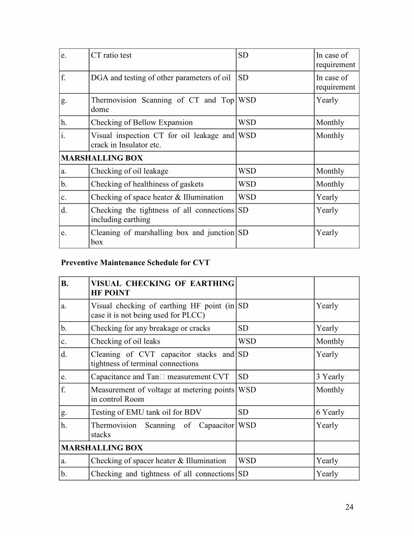
e. CT ratio test SD In case of requirement
f. DGA and testing of other parameters of oil SD In case of requirement
g. Thermovision Scanning of CT and Top dome
WSD Yearly
h. Checking of Bellow Expansion WSD Monthly
i. Visual inspection CT for oil leakage and crack in Insulator etc.
WSD Monthly
MARSHALLING BOX
a. Checking of oil leakage WSD Monthly
b. Checking of healthiness of gaskets WSD Monthly
c. Checking of space heater & Illumination WSD Yearly
d. Checking the tightness of all connections including earthing
SD Yearly
e. Cleaning of marshalling box and junction box
SD Yearly
Preventive Maintenance Schedule for CVT
B. VISUAL CHECKING OF EARTHING
HF POINT
a. Visual checking of earthing HF point (in case it is not being used for PLCC)
SD Yearly
b. Checking for any breakage or cracks SD Yearly
c. Checking of oil leaks WSD Monthly
d. Cleaning of CVT capacitor stacks and tightness of terminal connections
SD Yearly
e. Capacitance and Tan measurement CVT SD 3 Yearly
f. Measurement of voltage at metering points in control Room
WSD Monthly
g. Testing of EMU tank oil for BDV SD 6 Yearly
h. Thermovision Scanning of Capaacitor stacks
WSD Yearly
MARSHALLING BOX
a. Checking of spacer heater & Illumination WSD Yearly
b. Checking and tightness of all connections SD Yearly

25
including earth connections
c. Clearning of marshalling box and junction box
SD Yearly
d. Checking of healthiness of gaskets SD Yearly
*First time after one year from commissioning and then once in every three years.
Preventive Maintenance Schedule for Circuit Breakers
S. No. Tasks assigned Shut Down (SD) Or
Without Shut Down
(WSD)
Periodicity
A. SF6 CIRCUIT BREAKERS
a. Checking of SF6 gas pressures (wherever pr. Gauges provided)
WSD Monthly
b. Checking of oil leaks from Grading Capacitors
SD Monthly
c. SF6 gas leakage test SD Yearly
d. Dew Point measurement of SF6 gas SD 2 Yearly@
I. Hydraulic Operating Mechanism
a. Checking of oil level and replenishment topping up, if necessary
WSD Monthly
b. Checking of oil pressure WSD Monthly
c. Checking of oil leaks WSD Monthly
d. Checking of oil pressure drop during duty cycle operation check
SD Yearly
e. Checking of auto-starting/stopping of oil pump
SD Yearly
f. N2 Priming Pressure Measurement SD Yearly
II. Pneumatic Operating Mechanism
a. Functional checking of auto-starting of air compressors and dryers
SD Yearly
b. Maintenance of Air Dryer WSD Half Yearly
c. Checking of air pressure drop during duty cycle operation
SD Yearly
B. AIR BLAST CIRCUIT BREAKERS

26
a. Checking breaker air pressure WSD Monthly
b. Air (Pressure) Leakage check WSD Monthly
c. Dew Point Measurement of operating air at the outlet of Air Drier
WSD Yearly
C. MOCBs
a. Checking for oil leakage/oil level WSD Monthly
b. Testing of oil for BDV WSD Yearly
D. BREAKER OPERATION CHECKS
a. CB Operating Timings (Main, PIR, Aux.) SD Yearly*
b. Static Contact Resistance SD 2 Yearly
c. Dynamic Contact resistance (DCRM)** Contact Travel, Contact Speed, Contact wipe, Arcing contact length
SD 3 Yearly
d. Checking of Pole discrepancy relay SD Yearly
e. Functional checks, duty cycle operation including rapid re-closing (0-0 3s-CO)
SD Yearly
f. Checking of all operation lock-outs SD Yearly
g. Checking of all interlocks SD Yearly
h. Checking of pressure settings SD Yearly
i. Cleaning of Breaker Interrupter, Support insulators, PIRs and Grading Capacitors
SD Yearly
E. MEASUREMENT/TESTING
a. Checking of close/trip coil currents SD Yearly
b. Checking of healthiness of Operation Counter
SD Yearly
c. Capacitance and tan measurement of grading capacitors
SD 3 Yearly+
F. CONTROL CABINET
a. Checking of tightness of all cable terminations in MB
SD Yearly
b. Checking of door sealing gasket and replacement thereof, if necessary
WSD Yearly
c. Repainting of metallic surfaces (if required)
WSD Yearly
d. Checking of space heater WSD Yearly

27
@At time of commissioning then after 6 months and one & half years of commissioning and thereafter once in every two years.
*For All HV/EHV Circuit Breakers only
**For 400 kV BHEL, CGL make CBs only
+First time after one year from commissioning and then once in every three years.
Preventive Maintenance Schedule for Bus-Bar, Jumpers, Connectors, Clamps,
Switchyard Illumination etc.
S. No. Tasks assigned Shut Down (SD) Or
Without Shut Down
(WSD)
Periodicity
a. Measurement of station earth resistance WSD Yearly
b. Cleaning of insulators SD Yearly
c. Checking of insulators for cracks SD Yearly
d. Thermovision Scanning of all conductor joints. Terminal connectors clamps
WSD Yearly
e. Removal of hot spots SD Yearly
f. De-weeding of switchyard WSD In case of requirement
g. Repainting, rust removal of all structures, equipments etc.
SD Yearly
h. Checking of Switchyard lighting WSD In case of requirement
Preventive Maintenance Schedule for Protection Systems
S. No. Tasks assigned Shut Down (SD) Or
Without Shut Down
(WSD)
Periodicity
a. Testing of DR/EL WSD Monthly
b. Calibration of panel meters (Indicating/Recording instruments along with the transducers)
WSD Yearly
c. Calibration of Non-Tariff Energy meters WSD Yearly
d. Calibration of Tariff Energy Meters

28
e. Secondary Injection Test of individual protection schemes
SD Yearly
f. Checking of Voltage (in service) for relays WSD Yearly
g. Checking of DC drain of static relays WSD Yearly
h. Checking of DC drain of static relays WSD Yearly
I. LINE PROTECTION
A. DISTANCE PROTECTION
MICROMHO
Reach check for all 4 zones* WSD Yearly
Time measurement WSD Yearly
Power swing blocking check WSD Yearly
SOTF WSD Yearly
Level detectors of pps WSD Yearly
Fuse failure check WSD Yearly
Polarization check WSD Yearly
Nps detector check WSD Yearly
YTG
Reach check for all 4 zones** WSD Yearly
Timing check for the same WSD Yearly
PSB check WSD Yearly
DC Supply monitoring WSD Yearly
VT fuse failure check WSD Yearly
RAZFE
Reach check for all 4 zones** WSD Yearly
Timing check for the same WSD Yearly
PSB check WSD Yearly
VT fuse failure check WSD Yearly
LZ 96
Reach check for all 4 zones** WSD Yearly
Timing check for the same WSD Yearly
PSB check WSD Yearly
Opto coupler inputs check
29
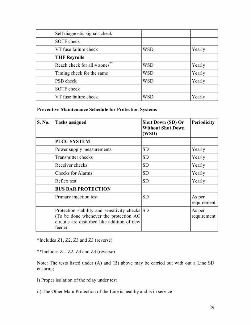
Self diagnostic signals check
SOTF check
VT fuse failure check WSD Yearly
THF Reyrolle
Reach check for all 4 zones** WSD Yearly
Timing check for the same WSD Yearly
PSB check WSD Yearly
SOTF check
VT fuse failure check WSD Yearly
Preventive Maintenance Schedule for Protection Systems
S. No. Tasks assigned Shut Down (SD) Or
Without Shut Down
(WSD)
Periodicity
PLCC SYSTEM
Power supply measurements SD Yearly
Transmitter checks SD Yearly
Receiver checks SD Yearly
Checks for Alarms SD Yearly
Reflex test SD Yearly
BUS BAR PROTECTION
Primary injection test SD As per requirement
Protection stability and sensitivity checks (To be done whenever the protection AC circuits are disturbed like addition of new feeder
SD As per requirement
*Includes Z1, Z2, Z3 and Z3 (reverse)
**Includes Z1, Z2, Z3 and Z3 (reverse)
Note: The tests listed under (A) and (B) above may be carried out with out a Line SD ensuring
i) Proper isolation of the relay under test
ii) The Other Main Protection of the Line is healthy and is in service

30
REACTOR PROTECTIONS
1 Reactor back up impedance SD Yearly
2 Carrier send for remote trip SD Yearly
3 Auxiliary relays (Buchholz. PRV. Etc) SD Yearly
4 Reactor differential protection SD Yearly
5 REF protection SD Yearly
6 DC logic SD Yearly
AUTO TRANSFORMER
PROTECTIONS
1 Over fluxing relay SD Yearly
2 Over load SD Yearly
3 Directional over current SD Yearly
4 LBB SD Yearly
5 Auxiliary relays (Buchholz. PRV etc.) SD Yearly
6 Fuse failure check SD Yearly
7 Transformer differential protection. SD Yearly
8 Restricted earth fault SD Yearly
Preventive Maintenance Schedule for Transformers and Reactors
S. No. Tasks assigned Shut Down (SD) Or Without Shut Down (WSD)
Periodicity
a. Checking of bushing oil level WSD Monthly
b. Checking of oil level in Conservator WSD Monthly
c. Checking of oil level in OLTC Conservator
WSD Monthly
d. Checking of cooler oil pumps and fans
i) Manual actuation WSD Monthly
ii) Auto Starting SD Yearly
e. Checking of oil leaks WSD Monthly
f. Checking condition of Silicagel in breather and regeneration if required
WSD Monthly
g. Measurement of BDV of oil WSD Half Yearly

31
h. Testing of oil for DGA and other oil parameters
WSD Half Yearly
i. Checking/Topping up of oil level in oil seal of breather
WSD In case of requirement
j. Vibration measurements (for Shunt Reactors only)
WSD Half Yearly
k. Measurement of BDV of OLTC oil SD Yearly
l. Tand measurement for Bushings SD Yearly
m. i) IR! measurement of Windings (Polarisation Index and DA+ Ratio)
SD In 3 Years**
ii) Tand measurement of Windings SD In 3 Years**
iii) Measurement of Windings resistance SD In 3 Years**
iv) Measurement of windings ratio SD In case of requirement
v) Measurement of short circuit Impedance
SD In case of requirement
n. External cleaning of Radiators SD Yearly
o. Cleaning of all Bushings SD Yearly
p. Frequency Response Analysis SD In case of requirement
q. Maintenance of OLTC driving mechanism
SD Yearly
r. Checking of all remote indications (STI and Tap position indicator)
SD Yearly
s. Electrical checking / testing of pressure relief device, Buchholz relay, OLTC surge Relay and checking/Replacement of the gaskets of the terminal box
SD Yearly
t. Checking/testing of Buchholz relay by injecting air or nitrogen
SD Yearly
u. Marshalling boxes of ICT/Reactor of: SD Yearly
i) Cleaning of Marshalling boxes of ICT/Reactor and OLTC
SD Yearly
ii) Tightening of terminations SD Yearly
iii) Checking of contactors, space heaters, illumination etc.
SD Yearly
v. Checking and Cleaning of Diverter Contacts
SD SOS (50, 000 Operations)

32
w. Checking of oil level and calibration of OTI, WTI
SD Yearly
x. Filteration /Replacement of Oil of OLTC SD In case of requirement
y. Filteration / Degassing of main tank radiator oil
SD In case of requirement
z. Testing of bushing CTs.
i) IR valve SD SOS
*Water content, BDV, SP, Resistance, Tand, IFT. Total Acidity, 2-Furfuraldehyde etc.
**First time after one year from commissioning and then once in every three years.
+Di-electric Absorption Ratio
!To be measured as per the following combinations:
N/E, N/LV and LV/E.
Preventive Maintenance Schedule for Isolators and Earth Switches
S. No. Tasks assigned Shut Down (SD) Or
Without Shut Down
(WSD)
Periodicity
A. Operating Mechanism
Maintenance of
a. Linkages including transmission gears SD Yearly
b. Stopper bolts SD Yearly
c. Cleaning of auxiliary switch contact & greasing with silicon grease
SD Yearly
d. Lubrication of operating mechanism, hinges, lock joints on levers, bearings
SD Yearly
e. Checking of all mounting bolts for tightness
WSD Yearly
B. MAIN CONTACTS
a. Cleaning and lubrication of main controls SD Yearly

33
b. Alignment SD Yearly
c. Main contact resistance measurement SD 2 Yearly
d. Tightness of bolds, Nuts and pins etc. SD Yearly
e. Cleaning of support insulators and checking of insulator cracks, if any
SD Yearly
C. EARTH SWTICH
a. Checking and Alignment of earthing blades
SD Yearly
b. Cleaning of contacts SD Yearly
c. Contact resistance SD Yearly
d. Operation of earthing switch SD Yearly
e. Checking of aluminum Copper flexible conductor
SD Yearly
f. Checking of earth connections of structure and MOM box
SD Yearly
D. MARSHALLING BOX
a. Visual check of auxiliary contacts SD Yearly
b. Cleaning and terminal tightness in MOM box
SD Yearly
c. Checking of space heaters and illumination
WSD Yearly
d. Checking of healthiness of gaskets WSD Yearly
Preventive Maintenance Schedule for Surge Arresters
S. No. Tasks assigned Shut Down (SD) Or
Without Shut Down
(WSD)
Periodicity
a. Checking of leakage current (Third Harmonic Resistive Current)
WSD Yearly
b. Testing of counters SD Yearly
c. Cleaning of LA insulator SD Yearly
d. Measurement of Capacitance and Tan SD In case of requirement

34
Chapter 4
MAINTENANCE TECHNIQUES FOR SWITCHYARD EQUIPMENTS (CB’s,
INSTRUMENT TRANSFORMERS, SURGE ARRESTORS AND ISOLATORS)
1.0 INTRODUCTION
This section briefly covers the maintenance practices / techniques being adopted by the power utilities for switch gear equipments installed in EHV/HV stations. However, in the present scenario competitive market utilities are under tremendous pressure to bring down the maintenance costs. This has led to the adoption of condition based monitoring rather than conventional based scheduled maintenance. The frequency of the condition-based maintenance is fixed based on the type of equipment and its previous history. Test or measurements are carried to determine the condition of the equipment. It is general experience of practically all the utilities that most of the equipment don’t show any abnormality during scheduled maintenance and there is no guarantee that the equipment shall not fail before the next schedule maintenance. Thus, the scheduled maintenance efforts are in vain as well as costly in view of shut-down time and manpower costs. Hence modern condition based techniques are being adopted which are designed to continuously monitor the function parameters and also assess the components deterioration before a mal-operation occurs.
2.0 MAINTENANCE TECHNIQUES
The maintenance techniques to be adopted should meet the following criteria:
• Field staff should be able to carry out such tests and interpret the test results • Testing procedure to be evolved after detailed discussions with the supplier of the equipment and testing equipment
• Return down procedure to be made available to the operating staff
3.0 GENERAL CHECKS / MAINTENANCE INSPECTION
The equipment should be inspected at the regular interval as per the guidelines given in Section 3. In addition the manufacturer guidelines should also be followed. The general checks normally required to be done are:
• General cleaning – cleaning of all insulators of CB/CT/CVT/Isolators for salt/dirt deposition, if any.
• Dust protection – even though the operating mechanism are made of steel and surface treated, still some rusting may take place. If any rust stains are observed the same may be cleaned with emery paper and paint the same against the rust protection. For protection against rust, soft grease (Ref- Manufacturer’s recommendation) is suggested.
• Tightness check – At the time of fuss inspection, all bolted joints on the breaker and operating mechanism shall be tightened up. All the wiring joints in the

35
terminal box of the operating mechanism shall be re-tightened at the regular intervals. Re-tightening has to be repeated only after bigger overhauls. Any SF6 gas leakage has to be detected with suitable gas leak detector.
• Lubrication – Bearings of the breaker and operation mechanism of isolators and breaker are to be lubricated with grease G after major overhauls.
• Treatment of gaskets – Any gasket opened once should be replaced by new one. All sealing surfaces and O-rings shall be sparsely greased of appropriate type for better sealing against this surface and at the same time providing protection against rusting/corrosion.
• Treatment of contact surfaces –
- Silver contact surfaces if required to be cleaned, the same to be done with soft cloth and solvent (Trichloroethane). Steel brushing or grinding is not permitted.
- Copper surfaces should be cleaned and oxide / sulphate free. If required to be cleaned the same should be done with cloth and solvent (Trichloroethane) or steel brushing. After steel brushing the surface need to be cleaned for loose particles and dust with the dry cloth / solvent (Trichloroethane).
- Aluminum contact surfaces should be cleaned with steel brush and emery cloth. Afterwards, clean it with dry cloth and apply a thin layer of vaseline.
• Moving contact surfaces
- Silvered: Cleaned if necessary, with soft cloth and solvent (tri-chloro ethane). No steel brushing. - Non silvered: Cleaned as silvered surfaces, can be steel brushed. After steel brushing they shall be thoroughly cleaned from loose particles and dust. - Lubrication: Lubricant - Grease K is applied in a very thin layer on the surfaces of the male contact and the puffer cylinder. The superfluous grease is carefully removed.
• Emptying and refilling of SF6 gas – SF6 gas for the circuit breaker is to be evacuated using the gas treatment equipment. SF6 gas contained in the electrical equipments should not be allowed vent into the atmosphere. Before SF6 gas is removed, the quality of the SF6 gas has to be checked. The gas after evacuation has to be stored in a suitable vessel meeting the following criteria
- Material should be such so as to resist the corrosive effects of SF6 decomposition products.
- Oil free
- Gas tightness of the service device and connecting components

36
- Gas storage in liquid or gaseous phase
- Suctioning upto 50m Bar
- Transportable and easy to handle
Operational contamination should be absorbed with a suitable filter unit provided in the gas handling plant. Filter unit should meet the following criteria:
- Dust particles able to be filtered safely
- Molecular sieves / filters remove humidity and SF6 decomposition products
- Desiccative in easily exchangeable cartridges for safe and trouble free disposal
- Inputs/outputs should be equipped with self-closing couplings in order to avoid a saturation of desiccative by ambient air. When SF6 gas is suctioned from a gas compartment, the gas is passed automatically through filters which will dry and purify the gas. Service devices has to be used by the maintenance staff to fill re-generated SF6 from the storage tanks in SF6 switch-gear and should meet the following criteria:
o Oil free o Easily handling and mobility o Filling pressure which can be pre-set by pressure reducer. Before filling the SF6 gas, the maintenance/over hauled breaker need to be evacuated by a vacuum pump so that SF6 gas does not mix with ambient air and also humidity and dust particles are removed from the breaker. With the help of vacuum pump a final vacuum should reach (5m Bar).
4.0 CONDITION BASED MONITORING TECHNIQUES – CIRCUIT
BREAKERS
Following are some of the important condition based maintenance techniques being adopted for assessing the condition of circuit breaker:
• Operating timings measurement • Contact resistance measurement • Contact travel measurement • Dew point measurement of SF6 gas/air • Tan delta measurement of grading capacitors • Vibration measurement • Operational lock-out checks • Trip/close coil current measurement • SF6 gas/hydraulic oil • Air leakage monitoring

37
• SF6 gas leakage test
Operating timings of Main / PIR contacts
Monitoring of operating timings is basically done with a aim of finding any problem in operating mechanism, alignment of main/arcing contacts and also discrepancy in timing between 2 poles and/or between two breaks of the same pole. Closing timing (maximum 1ms) and trip timing (maximum 25ms) are the most critical to be monitored very closely. Each type of circuit breaker has different operating timings. Initial values obtained at the time of commissioning should be taken as the base value. Any variation / drift in the timings from the guaranteed value/base value may indicate some type of problem with the operating mechanism or operating levers.
Precautions
• Ensure that SFT/PT is taken • Ensure that there are no joints in testing cable and the testing leads are not touching any live point
• Do not connect the test set the energized equipment • Ground cable must be connected first and removed at last • Ensure that high voltage plugs are free from moisture during installation operations
• CB analyzer body should be earthed (if separate earth is provided) • The testing equipment along with the testing procedure are available at site and the testing should be done in the presence of testing personal only.
• Clean the surface / terminal where the connection for testing are to be made • Clean earth point with sand paper / wire brush where earth terminal is to be provided.
• Ensure that all the pole strips simultaneously through single poles/trip command.
Testing procedure
A typical arrangement for measurement of operating timings of circuit breaker is given in Figure 1.

38
(Figure 1)
• Make connections as per above figure. Ensure that R, Y and B phase marking cables are connected with proper terminal with the CB (Circuit Breaker) analyzer and maintained color Coates for all the three poles of CB.
• Connection is to be made for measuring the operating timings of auxiliary contacts
• AC/DC supply to be extended to CB analyzer • Give closing command to closing coil of CB and note down the PIR and main contact closing time. Obtain a print from a CB analyzer
• Give tripping command to trip coil 1 of CB and note down the main contact tripping time.
• Repeat the same for tripping coil 2 • Note the down the timings of various operations of CB viz. CO, OC, OCO by giving appropriate command.
• In the event of PIR opening time is required the same may be isolated from the main break and treated as a separate contact using different channel of the analyzer.
Evolution of test results
The permissible pole discrepancy as per IEC 56 between 2 poles should not be beyond 1/6 of cycle (3.33 ms) and between 2 breaks should not exceed 1/8th of a cycle (2.5 ms). As per the practice followed by the most power utilities the limit for pole discrepancy between pole to pole is of the order of 5 ms for breakers under O&M as it is difficult to make any adjustments at site. If these timings are not within limits it may lead to over-stressing of one particular interrupting chamber. Switching over voltage may also be high in case of larger discrepancies in closing timings of the pole because of presence of trapped charges in the phase of circuit breakers which is going to close last.

39
Variation in the operating timing of the order of 3 ms from the base values is generally considered acceptable. However, if these are not within the limits the same is to be corrected by:
• Equalizing the SF6 pressure in different poles • Make necessary adjustment plunger of trip of close coil • Adjustment in operating mechanism • Changing trip / close coil if required
It is also necessary to measure the timings of auxiliary contacts from the point of view of variations with respect to main contact. If the difference in timings of the main or auxiliary contact is maintained within limits this reveals that there is no problem with the auxiliary contact assembly or with the operating mechanisms or with the operating levers of the CB.
Contact resistance measurement
Purpose of measuring contact resistance measurement is to assess the condition of the main contacts against erosion or misalignment of the main contacts. The value of the contact resistance for a new circuit breaker should be around 50 micro-ohms per break.
Testing procedure
The ohmmeter is employed for measurement of pumping resistance. To measure the value, connect the leads as per above figure and adjust the variac so that approximately 100 ampere current flow through the contacts. The value of the contact resistance is directly displayed on the digital LED display screen. By using the 4 terminal method effects of resistance of test lead is nullified is the input impedance of the measuring device is very high.
If the value of the contact resistance exceeds the permissible limits given in Section 7., this could lead to over heating of contacts. Monitoring contact resistance values is very good techniques for assessing the condition of main contacts. Resistance values of the order of the 100-125 micro-ohms per breaker is considered to be alright for the CB in service.
Dynamic contact resistance measurement
A typical arrangement for measurement of dynamic contact resistance of CB is given in Figure 2.

40
(Figure 2 )
This another technique for measuring the contact resistance during dynamic conditions i.e. during operations (close/trip) of CB. A DC current is injected through the CB and the current and voltage drop are measured and the resistance is calculated. The graphs of resistance vs. time data provide useful information on the condition of the main contact of CB and is considered to be a modern diagnostic tool.
The variation in the measure resistance vs. time will be seen as ‘finger print’ for the breaker contacts and can be used as reference / base value for comparing future measurement on the same breaker. If the DCRM values matches with the pre-commissioning /base value then the arcing contact are considered to be O.K. In case of wide variation and also there is change in arcing contact insertion time this shows erosion of arcing contacts. Such as situation may lead of transferring of current from arcing contacts to main contacts and subsequent commutation failure.
Contact Travel Measurement
Transducers and fixtures are attached to operating rod or interrupting chamber for measuring contact travel. When CB closes contact travel is recorded. Contact bouncing and any other abnormality is also pointed out by contact travel measurement. If contact travel is recorded with DCRM the length of the arcing contact shall also be monitored. It is generally observed that after some time due to erosion of arcing contact the tip length reduces and such condition may lead of commutation failure. This may lead to shifting to arc to main contacts and results in faster damage of main contacts. If contact travel, contact speed and contact restoration signature are compared with the original signature it shall reveal problems related with the operating mechanism, operating levers, main / arcing contacts, contact alignments etc.
Dew-point measurement of SF6 gas/air

41
6.4.3 Dew point is the temperature at which moisture content in SF6 gas/air starts condensing. Measurement of dew point of SF6 gas/air is considered to be a adequate parameter for monitoring of SF6 gas/air.
Dew-point measurement of SF6 gas in SF6 CB
6.4.4 Measurement of dew point of SF6 gas in a circuit breaker reveals the change in the value of dielectric properties of SF6 gas. Dielectric properties of SF6 dew get changed with time due to mixing of impurities like moisture, decomposition products of SF6 gas viz. hydroflouride lower valence sulphur fluorides etc. The ingress of moisture in SF6 gas after filling in CB and during O&M could be due to:
• Exudation of moistures contained during manufacturing from insulation materials used in circuit breakers.
• Permeation of moisture through sealed sections viz. gaskets ‘O’ rings etc. • In the event of presence of moisture in SF6 it gets hydrated to produce highly reactive H2SO3 and HF (hydrogen fluorides). These chemicals result in degradation of insulation and corrosion in the interrupting chamber. As such monitoring of moisture content in SF6 is considered to be very important. Chemical reactions taking place during moisture control conditions are given below:
(a) When moisture density is low
SF4 + H2O ................. SOF2 + 2 HF
SOF2 + H2O ................ SO2 + 2 HF
(b) When Moisture density is high
SF4 + 3H2O ................ H2SO3 + 4 HF
2SF2 + 3H2O ............... H2SO3 + 4 HF
Sulphur oxifulorides, hydrogen fluorides and H2SO3 formed during these reactions attack the materials containing silicon-dioxide (SIO2) viz. glass / porcelain. Primary and secondary decomposition in the presence of moisture forms corrosive electrolytes which may cause damage and operation failure.
Testing procedure
A typical arrangement for dew point measurement is given below in Figure 3.

42
(Figure 3)
Make the connection to the kit from circuit breaker ensuring that regulating valve is fully closed at the time of connection of the dew point kit. Regulate the flow rate of SF6 (0.2-0.5 L/minute) as per IEC 480, the value of the dew point is observed till it becomes stable.
Note.: If the regulating valve is provided at the outlet of the dew point kit then dew point value for rated pressure are to be monitored.
Frequency of Dew Point Measurement
The discharge of moisture from the organic insulating material is faster initially and the rate of release becomes almost negligible after 4 to 5 year of commissioning, and thereafter moisture entry in the CB is through permeation. Recommended frequency of dew point measurement is as given below:
• First time at the time of commissioning • After six months • After one year thereafter • Once in two years • Monitoring of Dew Point Values
Dew point of SF6 gas varies with the pressure due to the fact that saturation vapor pressure decreases with increase of SF6 pressure. Dew point of SF6 at higher pressure is lower than the dew point at atmospheric pressure. Table given below give the value of dew point at rated pressure and at atmospheric pressure for various makes of CBs.

43
Sl.No. Make of CB Dew point at rated
pressure (Min. º C) Dew point at
Atmospheric
Pressure (limit)
(Min º C)
Remarks
-15 - 36 At the time of commissioning
- 7 - 29 During O&M 1. BHEL
- 5 - 27 Critical -- - 39 At the time of
commissioning 2 M&BG -- - 32 During O&M - 15 - 35 At the time of
commissioning 3 CGL - 10 - 31 During O&M - 15 - 35 At the time of
commissioning 4 ABB - 5 - 26 During O&M -15 -36 At the time of
commissioning - 7 - 29 During O&M
5 NGEF
- 5 - 27 Critical
Dew Point Measurement of Air in ABCB
The dialectic properties / arc quenching properties of dry air do get change with the aging of CB and quality of air deterioration if moist air travel to the interrupting chamber. This will lead to deterioration of internal insulation and resulting in unsuccessful arc quenching. It is therefore necessary to carryout measurement of dew point of air in ABCBs.
Tan Delta and Capacitor Measurement of Grading Capacitor
6.5 The purpose of this measurement is to be detected any incipient weakness in the HV insulation. The grading capacitor play a vital role when circuit breaker trips TRV stress conditions and also in open condition of circuit breakers. Electrical and thermal stresses produced during operation of CB do lead to degradation of paper insulation of capacitor, capacitor elements and also to the oil in grading capacitors. The value of the tan delta or loss angle increases with degradation of paper or oil. A typical arrangement of tan delta measurement is given below in Figure 4.

44
Figure 4
Testing procedure
• Connect LV cable to the middle of the double interrupter • Connect HV cable to the other end of grading capacitor to be tested • Ground the opposite end of the grading capacitor using earth switch • Measurement to be done in UST mode • Follow the procedure provided by the equipment supplier. • Measurement to be made at 2 kV first and then at 10 kV. • Carry out the measurement in the standard mode and also the high quality mode
Factors affecting test results/measurements
1. Temperature – The dialectic losses of most insulation increases with temperature. A rising temperature causes a rise in dialectic loss which in turn causes a further rise in temperature. This is general tendency for capacitance to increase with the temperature. Deterioration of insulation due to aging causes exponential rise of tan delta with the increase in temperature and is expressed as follows:
Tan δ T = Tan δ E α (T – To )
Where T0 = 20° C
T = Temperature of the specimen
Tan δ To = Tan δT at temp. T
α = Temperature coefficient varies between 0.01 and 0.015° C
(if the α value is between .05 and 0.3 it considered as questionable conditon. Value of α more than .03 is a sign of alarming condition)

45
2. Deposit of surface moisture can have significant effect on the surface losses and consequently on the results. With a view to minimizing the errors the dissipation measurements may be made when the weather is clear and sunny and the relative humidity is less than 80%.
3. Surface leakages – Any leakage over the insulation surfaces of the specimen will get added to the losses in the insulation and make a fake impression about the condition of specimen. It is recommended that surfaces of insulation should be cleaned and dry when taking a measurement.
4. Electrostatic interference – In the energized switch yard, readings may get affected by electrostatic interference current resulting from the capacity coupling between energized line and the bus work to the specimen. To overcome this all the jumpers connected need to be opened when taking a measurement. In the modern automatic testing kits the effect of interference gets nullified due to presence of interference suppression circuits.
Interpretation of test results
A large number of failures of electrical equipment have been reported due to deteriorated condition of the insulation. The correct interpretation of test results requires knowledge about the equipment construction and characteristics of particular type of insulation.
Dissipation factor measurements indicate the following conditions in the insulation of wide range of electrical equipments:
1. Chemical deterioration due to time and temperature, including certain cases of acute deterioration caused by localized overheating;
2. Contamination by water, carbon deposits, bad oil, dirt and other chemicals; 3. Severe leakage through cracks and over surfaces; 4. Ionization.
Dialectic strength of insulation decreases with the increase in the moisture content. At high temperature is pushed out of the paper insulation with oil. As insulation cooled down water starts migrating from oil into paper. The time for temperature drop may be faster as compared to water returning to cellulose material. Depending upon the condition the dissipation factor also changes.
An increase in the value of tan delta indicates the deterioration of cellulose insulation whereas increase in both tan delta and capacitance reveals entry of moisture in the insulation.
Ambient temperature
At 20 degree C the value of tan delta should not be more than 0.007. In the present testing kit available the software is available to give the test results at 20 degree C and also at rated frequency irrespective of the measurement being made at some other temperature.

46
Vibration Measurement
Mechanical vibrations experienced during closing and tripping operations are recorded with the help of accelerometer and data acquisition system. The same fingerprints are compared with the reference signature, which have been recorded at the time of pre-commissioning. Any change in the recorded patterns could be attributed due to any mechanical malfunctions, excessive contact wears, misalignments of contacts, problems in damping systems. For a measurement of recording of vibration pattern 2 or 3 accelerometer are installed externally in each phase usually one on arching chamber, one in operating mechanism and one somewhere in-between.
Other Condition Based Maintenance Techniques
Besides the above mentioned condition based techniques, the other techniques adopted includes – monitoring of trip / close coil current, coil current measurement, SF6 gas/air leakage test rate and operating mechanism medium oil/air pressure. Friction in the plunger movement gap between the plunger and the pin of the coil assembly are reflected in the recorded current values / wave shapes. Leakage rate of SF6 gas indicates healthiness of the ceiling system, O ring and strength of cementing joints. SF6 gas leakage upto 1% per annum is considered to be within acceptable limits.
Operation Lockout Checks for CB
Following operation lockout checks are carried out:
a) SF6 gas pressure lockout:
• Low pressure alarm • Operation lockout alarm
b) Pneumatic operating system lock-out
• Compressor star / stop switch • CB auto reclose lock-out switch • CB closing lockout • CB operation lockout • Mechanical closing interlock (applicable for air blasé CBs)
c) Hydraulic operating system lockout
• Pump start/stop • CB auto re-close lockout • CB closing lockout • CB operation lockout •

47
Evoluation of Test Results
a )SF6 gas pressure lockout: All the SF6 gas pressure switches settings should be checked and corrected with ambient temperature. Settings of SF6 gas pressure switches should be within + 0.1 bar/Kg/cm2 of the set value (after taking into account the temperature correction factor).
b) Air pressure lockout: All the air pressure switches settings should be checked and corrected and should be within + 0.1 bar/Kg/cm2 of the set value.
c) Oil pressure lockout: All the oil pressure switches settings should be checked and corrected and should be within + 0.1 bar/Kg/cm2 of the set value.
Maintenance Techniques for Instrument Transformer
Instrument transformers are generally the most reliable EHV network equipment. However, violent failure/blasting due to primary insulation of instrument transformers may lead to considerable damage to nearby equipments and O&M personals. In order to avoid violent failures following maintenance techniques have been adopted like measurement of tan delta and capacitance, insulation measurements, DGA monitoring, recovery voltage measurement etc.
Tan Delta and Capacitance Measurement (CT/CVT)
1. Testing mode for CTs: CTs provided with test steps have to be tested in UST mode whereas CT with test step are to be tested in GST mode. Before carrying out the test it may be ensured that jumpers are disconnected and CT/CVT porcelene housing / insulators are thoroughly cleaned.
2. Testing mode for CVTs: HF panel and neutral terminal of EMU transformer are to be disconnected and isolated from ground before carrying out the test. The testing kit which is similar as used for grading capacitors for CB is to be connected between HV/HF points and measurements are done in UST mode. In the event of test values deviating from the base values, individual capacitor stacks are to be tested in UST mode.
Besides the above testing modes the connection to be made as follows:
CTs with test taps
HV terminal of the tan delta kit should be connected to HV (primary) terminal and LV terminal should be connected to ten delta test tap.

48
CTs without test taps
HV terminal of the tan delta kit to be connected to the HV (primary) terminal and LV terminal to be connected to the ground/earth.
Standard procedures as recommended / prescribed by the kit supplier may be adopted. Measurement may be carried out at 2 kV first and then at 10 kV. Carry out the measurement in the main and reverse polarity and compute the average value. Evaluation of test results is just similar to as described for CBs. Major factors affecting the measurement are also same as applicable to CBs.
Insulation Resistance Measurement (CTs)
Testing procedure: A typical arrangement for IR measurement for CT is given
below:
Figure 5
Connect the megger as shown in the figure. Connect the HV terminal to the primary terminal of CT by using crocodile clip for firm grip. The measurements may be made as per the procedure prescribed by the supplier of the kit. A test voltage as specified is applied as per the above connections and successive readings are taken. Values of IR should be recorded after 15, 60 and 600 seconds. Ambient temperature and weather conditions are also to be noted. It is advisable to carry out measurement during sunny and clear weather.
Evolution of test results
Variation from normal IR value indicate abnormal conditions such as presence of moisture, dirt, dust, crack in insulation of CT and degradation of insulation.

49
Analysis of IR values
When a DC voltage is applied to insulation, there will be a flow of conduction current, dialectic absorption current and charging currents. Dialectic absorption current and charging currents becomes zero after some times and only conduction current only flows through the insulation.
Conduction current
The steady straight value of the current after a DC voltage is applied to the capacitor is known as conduction current. Conduction current is directly affected by temperature, humidity, contaminants and voltage stress. In a solid insulating material which have absorbed moisture, there will be a non linear larger increase of conduction current for increase in the voltage stress.
Test is carried out at 5 kV DC voltage. Any variation with respect to base value indicate problem in CT insulation.
Polarization index (IR60/IR15) and dialectic absorption ratio (IR600/IR60) are calculated and these ratios should be more then 1.5 for good quality insulation. However, exact values depend on the type of insulation and may vary for different type of equipment.
Secondary Winding Resistance (CTs)
Testing procedure
After ensuring, necessary precautions have been taken, connect leads of O meter between different terminals of CT secondary course. Select the range of O meter as per pre-commissioning / factory test results. Following precautions are considered essential:
1. Test links should be open in the CT MB prior to measurement of secondary resistance
2. It should be ensured that associated CTs are not in charged condition. For example main and tie CTs for differential relays should not be in charged condition.
3. Any earth provided in the secondary circuit of CT should be removed prior to measurement.
Evolution of test results
Value of secondary winding resistance should be within the acceptable limits. Extreme low value of resistance indicates turn-to-turn shorting, whereas, if the value is high it indicates some loose connection which has to be identified and tightened before repeating the measurement.

50
Secondary voltage measurement for CVTs
Failure of capacitor elements in C1 or C2 side results in change in output voltage. Regular and close monitoring of secondary voltages using 0.2 or 0.5 accuracy class multimeters, secondary voltage change can be monitored. If voltage of a particular phase CVT drifts by more than + 1 volts, it requires thorough investigation.
DGA monitoring
Due large number of failures of CTs, DGA monitoring has been recently introduced for checking / assessing the health of insulation of CTs. In these monitoring different dissolved gases like H2, CH4, C2H6 etc. are tested. DGA results are analyzed as per IEC-60599. It is being proposed to do DGA monitoring on three yearly basis. This shall require special arrangement for oil sampling as well topping of oil when oil levels falls down.
N2 pressure monitoring
Some of the CTs are provided with N2 cushion at the top of the CT to avoid ingress of moist air from atmosphere during normal contraction/expansion of oil due to change in temperature (due to load or ambient variations). N2 pressure is to be maintained at about 0.30 to 0.50 bar above atmosphere hence monitoring of the same is very important. In case of leakage of N2 gas, CT will breathe with atmospheric air moisture may enter in CT oil/paper insulation. This moisture entry will lead to abnormal/accelerated ageing of the insulation and may even cause pre-mature insulation failure.
Magnetic Characteristic of CT Cores
Before carrying out the test following precautions may be taken:
1. Test links should be open in the CT MB prior to measurement of secondary resistance
2. It should be ensured that associated CTs are not in charged condition. For example main and tie CTs for differential relays should not be in charged condition.
3. Any earth provided in the secondary circuit of CT should be removed prior to measurement.
4. Applied voltage to the CT should not exceed the rated Knee Point Voltage.
Testing procedure
After making proper connections apply voltage is increased from zero to rated Knee Point Voltage in steps of 25%, 50% 75% and 100%. Measure the current the drawn by the CT secondary core at respective applied voltage and record the test results as per the prescribed formats.

51
Evolution of test results
The magnetization test is conducted in order to see the condition of turns of CT secondary. This test shall give indications regarding shorting of turns CT secondary winding. Magnetisation characteristics also indicate the suitability of CT for keeping it in service or not.
Knee point voltage is normally defined as the voltage at which 10% increase in the applied voltage causes 30 to 50% increase in secondary current. The magnetization current at rated Knee Point Voltage should not be more than the specified/designed value.
A curve can be drawn between applied voltage and magnetizing current. From the magnetizing curve it can be implied that up to rated KPV (knee point voltage), the V-I curve should be almost a straight line. However, if this line is not linear, this indicates that the magnetizing characteristics are not desirable. If the slope of the curve starts increasing it indicates that magnetizing induction becomes low and total primary current is utilized in exciting the core alone. Consequently, output of CT secondary disappears.
Maintenance Technique for Surge Arrestors
Presently the- monitoring of total leakage current (capacitive and resistive currents) is being used by many utilities. Leakage current monitors are permanently connected with the surge arrestors, and in case of high leakage current surge arrestors are removed from surge arrestors. However, it is felt that this method is not the fool proof method as the total leakage current, which is purely capacitive, does not give precisely the health of the surge arrestors. There have been the cases when the surge arrestors have blasted even though total leakage current value was below the limit prescribed by the manufacturers. Recently, another monitoring method for monitoring the health of the surge arrestor have been introduced wherein measurement of resistive current is done which indicates degradation of ZnO / SiC disc. This method has been prescribed in IEC 60099 (5). Resistive current is current is 15-30% of total current and since capacitive and resistive currents are at 90 degree face shift even considerable change of resistive current results in very small increase in the total current. Hence monitoring total leakage current may not truly indicate the degradation of ZnO disc. Degradation of long linear ZnO disc generally leads to harmonics in the leakage current when system voltage of fundamental frequency is applied. Third harmonic resistive current measurement is based on filtering of third harmonic component from the total leakage current. Leakage current of the order of about 500 micro amps is generally considered to be safe.
Measurement of Resistive Leakage Current or the Power loss
The resistive part of the leakage current or the power loss can be determined by several methods given below:

52
Using a voltage signal as reference
The method relies on using a reference signal representing the voltage across the arrester. The reference signal can be used for direct reading of the resistive component of the leakage current at the instant when the voltage is at its peak (dU/dt=0). The voltage and the resistive current level can be read with an oscilloscope or similar device. This method is commonly used in the laboratory for accurate determination of the resistive current since the reference signal is easily accessible through a voltage divider having a sufficiently small phase-shift.
In practice, the accuracy is limited mainly by the phase-shift of the reference signal and by the deviations in magnitude and phase of the voltage across the non-linear metal-oxide resistors at the earthed end of the arrester. The presence of harmonics in the voltage may further reduce the accuracy of the method.
A restriction on the method during measurement in service is the need for a reference signal. Temporary connection to the secondary side of a potential transformer or to the capacitive tap of a bushing is necessary and may be complicated to obtain. The capacitive currents induced in the earth connection of the arrester by adjacent phases may reduce the accuracy during measurements in service.
Compensating the capacitive component by using a voltage signal
By using a voltage signal to compensate the leakage current for its capacitive component, the sensitivity in the measurement of the resistive part may be further increased. The basic principle is a HV bridge where the capacitive-resistive arm is adjusted to balanced the capacitive component of the leakage current so that only the non-linear resistive part contributes to the output voltage, which can be studies with the help of an oscilloscope.
The bridge is balanced when the voltage is close to zero and with the capacitive current being at its peak. Since the differential capacitance of the arrester is voltage dependent (the capacitance is constant, the remaining current after compensation comprises not only the resistive component, but also a capacitive part. In this method also the accuracy may be reduced by phase shifts in voltages and currents due to the influence of adjacent phases.
Compensating the capacitive component without using a voltage signal
This is a compensation method where the need for a voltage signal is eliminated. The basic principle is that a reference signal of fundamental frequency is created synthetically by means of information derived from the leakage current. By proper adjustment of the amplitude and phase angle, which can be done automatically or using an oscilloscope, the reference signal can be made to compensate the capacitive component of the leakage current. The method can be implemented with different degrees of sophistication.

53
This method can readily be utilized for measurements in service. A potential problem is the presence of harmonics in the voltage, which cause harmonic capacitive currents that may interfere with the resistive component.
Capacitive compensation by combining the leakage current of the three phases
The method is based on the assumption that the capacitive currents are canceled if the leakage currents of the arresters in the three phases are summed. The resulting current is composed of the harmonics of the resistive currents from the three arresters, since the fundamental components are also canceled as long as they are equal in magnitude. If there is an increase in the resistive current of any of the arresters, the capacitive currents remaining constant, the increase will appear in the summed current. A voltage reference signal is not needed. For measurements in service, the main disadvantage with the method is that the capacitive currents of the three phases are not generally equal. Another concern is the influence of harmonics in the system voltage, which will cause harmonics in the Summed current.
Third harmonic analysis
The method is based on the fact that harmonics are created in the leakage current by the non-linear voltage-current characteristic of the arrester. No voltage reference is needed since it is assumed that all harmonics arise from the non-linear resistive current. The harmonic content depends on the magnitude of the resistive current and on the degree of non-linearity of the voltage-current characteristics.
The third harmonic is the largest harmonic component of the resistive current, and it is the most commonly used for diagnostic measurements. The conversion from harmonic to resistive current level, if required, relies on information supplied by the arrester manufacturer or from measurements in the laboratory.
The method can be readily used for measurements in service. The main problem is the sensitivity to harmonics in the system voltage. The harmonics in the voltage may create capacitive harmonic current that are comparable in size with the harmonic currents generated by the non-linear resistance of the arrester. As a result, the error in the measured harmonic current may be considerable. This is shown in Figure 6, where leakage current is given as function of the third harmonic content in the system voltage. The figure includes the effects of different voltage-current characteristics and capacitances, as well as the influence of the phase angle of the third harmonic in the voltage. It is seen that 1% third harmonic in voltage may give + 100% measuring error in the current.

54
Figure 6
Third order harmonic analysis with compensation for harmonics in the voltage
The method is based on the same principle as mentioned above, but the sensitivity to harmonics in the voltage is greatly reduced by the introduction of a compensating current signal for the capacitive third harmonic current in the arrester. The compensating current signal is derived from a "field probe"L positioned at the base of the arrester. After proper scaling, the harmonic current induced in the probe by the electric field in subtracted from the total harmonic current. The result is the harmonic current generated by the non-linear resistive current of the arrester. The conversion from third harmonic to resistive current if wanted requires additional information from the arrester manufacturer. The method is suitable for measurements in service and is described in more detail below.
Direct determination of the power losses
The power loss is the integral of the product of the instantaneous values of the voltage and leakage current divided by time. The power loss may be expressed in terms of the product of the r.m.s. value of the resistive component of leakage current and the r.m.s. value of the voltage across the arrester. The influence of the harmonics in the voltage is greatly reduced by the multiplication and integration procedure. The main disadvantage is

55
the need for a voltage signal. The accuracy during measurements in the service may be limited by phase shifts in voltages and currents, caused by the adjacent phases.
Monitoring System with Compensation of the Third Harmonic Current Generated
by the System Voltage
The use of modern diagnostic techniques means generally increased service reliability and cost savings for the electric power industry. It is therefore desirable to check the condition of surge arresters at regular time intervals, by measuring the resistive component of the continuous leakage current in service without de-energizing the arrester. Reliable measurements are achieved by introduction of a field probe as illustrated in Figure -6, which allows a compensation for the harmonic currents generated by the harmonics in the voltage.
Experience from measurements on arresters for system voltages from 66 kV to 765 kV have prevented arrester failures and increased the operation reliability.
The leakage current monitor system is used for gap less metal oxide surge arresters and is connected to the arrester as illustrated in Figure-6. It consists of three main parts:
• A current probe attached to the connector of either a clip-on current transformer or a toroid-transformer in case of permanent installation.
• A field probe positioned near the base of the arrester to pick up the capacitive current component, is connected to the current probe via coax cable and an adaptor. A telescope rod of insulating material is used to locate the field probe at the correct position
• A leakage current instrument, using harmonic analysis of current and field probe signals to determination of the resistive component of the leakage current.
The equipment may be used in three different ways:
• As a portable instrument for checking the conditions of the surge arresters on a regular basis.
• To Monitor the condition of an arrester during a shorter or longer period of time, for instance to investigate in more detail the behavior of an arrester that shows a leakage current higher than expected.
• Permanently installed for continuous registration in substations of big importance to the operation reliability of the system.
Resistive Leakage Current Measurement for LA
Testing procedure
1. Make the connections as per the diagram given below in Figure-. 2. The kit should be properly earthed as per the recommendations of the kit suppliers.
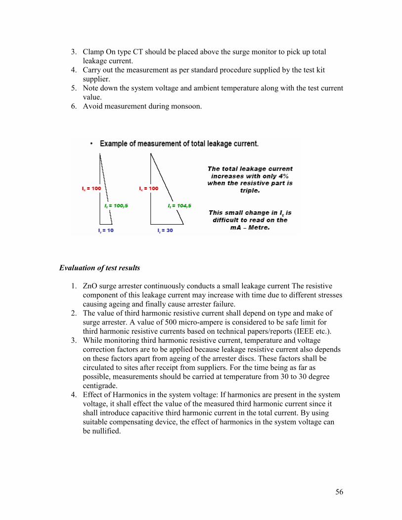
56
3. Clamp On type CT should be placed above the surge monitor to pick up total leakage current.
4. Carry out the measurement as per standard procedure supplied by the test kit supplier.
5. Note down the system voltage and ambient temperature along with the test current value.
6. Avoid measurement during monsoon.
Evaluation of test results
1. ZnO surge arrester continuously conducts a small leakage current The resistive component of this leakage current may increase with time due to different stresses causing ageing and finally cause arrester failure.
2. The value of third harmonic resistive current shall depend on type and make of surge arrester. A value of 500 micro-ampere is considered to be safe limit for third harmonic resistive currents based on technical papers/reports (IEEE etc.).
3. While monitoring third harmonic resistive current, temperature and voltage correction factors are to be applied because leakage resistive current also depends on these factors apart from ageing of the arrester discs. These factors shall be circulated to sites after receipt from suppliers. For the time being as far as possible, measurements should be carried at temperature from 30 to 30 degree centigrade.
4. Effect of Harmonics in the system voltage: If harmonics are present in the system voltage, it shall effect the value of the measured third harmonic current since it shall introduce capacitive third harmonic current in the total current. By using suitable compensating device, the effect of harmonics in the system voltage can be nullified.

57
Battery and Battery Charger
Following test may be carried out for determining the health of battery/battery charger.
a) Battery
• Capacity test/discharge test of battery bank • Measurement of impendence of battery cell • Checking of electrolyte level and topping up with DM water • Checking of emergency DC lighting to control room • Checking of electrical connection of charger panel for tightens and cleaning • Checking of electrical connection for battery for tightness • Checking of tightness of all electrical connection of DC distribution board
b) Battery charger
• Procedures/checks for identifying the probable faults. Following are the procedures for identifying the probable faults
S.No. Problem Possible cause Remedial measures
1. No DC output - Problem in control cards
- Check the control cards as per details given below
- Transformer supply failure
- Replace if found defective
- Fuse blown - Replace
- Loose connections in transformer and controller
- Tight if found loose
2. DC voltage not building up or dropped on load
- Rectifier fuse blown Replace blown fuse
- Current limit in operation
- Check current limit setting and adjust
- Problem in control cards
- Check the control cards as per details given below
3. Output ripple high
- Filter fuse blown - Replace blown fuse
- One SCR not conducting
- Rectify
- Potentiometer setting disturbed in Firing card
- Adjust the setting with skilled hand/carefully or card to be sent to factory/replace with new card
4. Output voltage - problem in control - Check amplifier card for reference level

58
shooting high in auto mode
card and comparator output as per description given below.
5. Output voltage low
- Loose connection - Tighten all connections
- Stability potentiometer disturbed in amplifier card
Adjust carefylly the stability pot. In amplifier card.
• Test of control cards 1. Power supply card 2. Firing card 3. Amplifier card 4. Current limit indication card 5. Pulse card 6. Over current/over voltage card
E. Power Line Carrier Communication
Various maintenance test required to be carried out are normally done as per suppliers guidelines.
F. Protective Relays
A large number of different types of protection schemes / arrangements have been under use at different sub-station. Their quite diverse due to their being supplied by different manufacturers having various design philosophy. In order ensure healthiness and maximum availability of protective relays it is necessary to carryout periodic testing. Presently, manual as well as microprocessor based automatic testing kits are available. While the manual kits have been in use by utility engineers in past, automatic test kits are relatively recent introduction. Apart from automatic testing capability, these kits are also capable of replaying the fault recordings captured by disturbance recorders as well as transient simulation done using Electro Magnetic Transient Programme (EMTP). Also, it is possible to do comprehensive end to end testing of line protections including protection signaling with use of these automatic kits in conjunction with time synchronizing equipment. Utilities may decide on requirement of manual or automatic kits depending on size of their network and testing practices.
Testing requirements
• Manual test kits 1. Portable cover current relays testing equipment. The input rating shall be between 200-250 V. 50 Hz., AC supply and the current output range shall be 0.05-200 amps. With negligible harmonic distortion of less than 1%. A time interval meter shall be fitted to read and display 0-10 seconds with an accuracy of + 10 milliseconds.

59
2. Portable test equipment for testing distance relays comprising supply unit, control unit and fault impedance unit. Suitable for AC voltage from 380-440 V, three phase, 3 wire system 20 Ampere (short time rated) with built in safety devices.
• Automatic test kits 1. It shall be suitable to test all types of distance, over current, ground relays, synchronizing, transformer, reactor and busbar protection relays of major manufacturers in automatic as well as manual mode.
2. It shall include all the accessories required for making the complete test set up.
3. It shall have three phase current output range 0-30 amps. (rms) and three phase voltage range 0-110 voltage (PH-G).
4. It shall work on single phase 240 V, 50 Hz + 10% SUPPLY 5. Shall include necessary software and hardware
i) To accept fault recording available from fault data recorder/numerical relay/EMTP simulation and relay these on the relay under test.
ii) To draw the relay characteristics
6. The accuracy of relay test kit shall be as follows:
i)1 % for voltage and current output and resolution of time measurement of 1 ms or better

60
Chapter 5
Maintenance of Transformers and Reactors
1.0 INTRODUCTION
1.1 The techniques / procedures being adopted for both preventive maintenance and condition based monitoring in respect of EHV transformers and reactors is briefly discussed in this section.
2.0 GENERAL MAINTENANCE
2.1 A power transformer in a sub-station is not only one of the costliest equipment but is also one of the most important links of the power system. If the power transformer is required to give a trouble free service it should receive proper attention for its maintenance. General maintenance, which is normally required to be done on transformers, is as under:
1. Regular inspection of the external surface of transformer for any dirt and dust and when required the same may be cleaned
2. Regular inspection of the external surface for any damages due to rust 3. Possible rust damages when noticed are to be removed and surface treatment restored in the original state by means of primer and finished paints for minimizing risk of corrosion and its subsequent spreading
4. Before carrying out any maintenance work ensure proper safety procedures as per utility practice and ensure the following:
a) The transformer and the associated equipment should be taken out of service, isolated and properly earthed
b) Obtain a permit to work / sanction for carrying out tests from the shift engineer
c) Obtain the keys for the transformer area
Following checks may be carried out
1. Check for signs of corrosion 2. Check all joints for any sign of leakage 3. Check for any sign of mechanical damage 4. Check oil levels 5. Check that surrounding areas are clean and tidy
All results must be entered in the proper format for comparison during future tests.

61
Silica Gel Breather
2.2 Check the colour of the silica gel breather so as to prevent any deterioration of silica gel breather. It is recommended to replace the same when half to two third of the silica gel has become saturated and become pink in colour. Failure to comply this will result in decreasing the drying efficiency of the breather. Silica gel breather could be reactivated while wilst in its charge container or it can be emptied into a shallow tray. It is required to be heated in a well ventilated oven and a temperature of 130-138 degrees till the entire mass achieve the original blue colour. Immediately after reactivation the new silica gel must be placed in a sealed container to avoid any absorbance of moisture while cooling.
Drycol Breather
2.3 Following checks may be carried out
• Check for operation of counter reading - This may be done on a regular basis so as to see the functioning of the counter.
• Check for defrost current indication and counter reading - This is being done to ensure the water is being ejected from the breather. Check the same by pressing the button. Also, check that 2 red neon lights are on and the ember neon light is off.
Conservator Oil Level - Visual Checks
2.4 Visual checks may be carried out on regular basis for conservator oil levels. If the level is normal no action is required. In the event of above or below normal level action has to be taken to add or remove some of the oil. The correct oil filling level is normally is to be specified on the information plate. At a temperature of 45 degree C the conservator should be half filled. If the level shows the value full oil must be drained off. If it is low oil must be added immediately.
Check for Marshalling Cubicle and kiosks
2.5 Following checks may be carried out and all results may be recorded in the format of comparison during future checks.
1. Condition of paint work
2. Operation of door handles
3. Operation of doors and hinges
4. Condition of door seal
5. Door switches working
6. Lights working
7. Heater working
8. Thermostats working
9. Operation of heating and lighting switches
10. Mounting of equipment secure

62
11. Manual operation of switches satisfactory
12. Checking of tightness of cable terminations
13. Checking of operation of contractors (isolating the trip signal, if any)
14. HRC fuses and their rating
15. Operation of local alarm annunicator by pushing push buttons provided for
lamp test, acknowledge, reset, system test, mute etc. to cover all system
function
16. Source change over test check by putting off power sources alternatively
17. Check for plugs for dummy holes and replacement, if found missing.
Note: Transformer / shunt reactor need not be taken out of service / isolated or earthed while carrying out the above checks.
Valve Operation Checks
2.6 Following checks may be made either at the time of erection or after a major overhaul. All results must be recorded in the log for comparison during future tests.
1. Check each value for free operation 2. Check that each valve is padlocked where applicable 3. Check that each valve is adequately greased 4. Check that each valve returns to its "in service" operating position (open or closed)
Cooling System
2.7 Regular inspection may be carried out of the cooling surfaces and when required clean same from the dirt, insects, and leaves or any other air borne dirt. This is important as it affects the fan cooling. Cleaning is normally done by water flushing at high pressure. As regards cleaning of internal cooling surfaces, no major are considered necessary so long the oil is in good condition. In the event of setting of sludge formation of the oil the sludge may get deposited from the horizontal surfaces in radiators and coolers. The same may be flushed internally with clean oil in connection with oil exchange. In the event the sludge doesn't gets loosed the flushing may be done first with petrol and then with oil. However, this may be carried out in consultation with the supplier.
2.8 Regular inspection of the cooler banks may be made. The cooler can be cleaned by taking out the tube packets and thereby making them assessable for cleaning. For any increase in sound level of fan retighten all mounting supports.
Cooling System - Fans - Controls
2.9 Fan control are designed to operate both manually and automatically. The automatic function is related to the load and energisation or both. The following controls are required to be checked.

63
1. Manual Control - Fan operation should observed after turning the switch to ON position for a brief period. Oil pump should be checked by observing the flow through gauges. In case of any malfunctioning manufacturers may be consulted.
2. Temperature Control - Remove the temperature bulbs from its well on the side / top of the transformer. Set the master controller to the automatic position. The temperature of the bulb should be slowly raised by using a temperature control calibration equipment for observe for proper calibration / operation.
3. Load Control - Check the secondary current of the controlling CT for proper operation. Shot the secondary of CT (if the transformer is energized). Remove the secondary lead from the control circuit and inject the current to the control circuit. Vary the level of the current to observe the proper operation.
Cooling System - Fan - Visual Inspection
2.10 Following visual inspection checks may be carried out without taking a shut down of the transformer to check that the fans are operating at a designed speed, airways are not blocked and guards and blades are not damaged.
1. Visual check for contamination of motor and fan blades 2. Check for build up of moisture in the motor 3. Check bearing lubrication 4. Check for correct rotation 5. Check for unusual noises 6. Check for corroding parts
Cooling System - Pumps-Visual Checks
2.11 Following visual inspection checks may be carried out without taking a shut down of the transformer
1. The transformer and associated equipment need not be out of service or isolated while carrying out visual checks on the pumps.
2. Obtain a 'Permit to Work' from the Shift Engineer 3. Obtain keys to the transformer compound and marshalling kiosk 4. All results must be recorded in a log for comparison during future tests in service. 5. Following checks should be carried out
a) Check for correct rotation b) Check for unusual noises/abnormal vibration - replacement of rotor and bearings c) Check for corroded parts d) Check for electrical problems
Winding Temperature Indicators - Test
2.12 Following tests may be carried out:

64
1. Cooler control, alarm and trip test 2. Temperature indication calibration of WTI bulb 3. Secondary induction test
Before carrying the tests it may be ensure that the transformer and the associated equipment is deenergised, isolated and earthed.
Cooler control, alarm and trip test
The setting of temperatures should be as per the approved scheme. The values given below are indicative values. However, these values are not to be taken for granted and are to be verified with manufacturers instruction manual.
- Access the local winding temperature indicator and set the temperature indicator pointer to the first stage of cooling value (65 degree C).
• Check that the fans of those coolers set to first stage are operating.
- Set the temperature indicator pointer to second stage cooling value (80 degree C).
• Check that the fans of those coolers set to second stage are working.
- Set the temperature indicator pointer to the alarm value (110 degree C).
• Check with the control room that the alarm signal has been received.
- Set the temperature indicator pointer to the trip value (125 degree C).
• Check with the control room that the trip signal has been received.
Temperature indication calibration of WTI bulb
Remove the WTI bulb from the transformer pocket and insert the bulb into the calibrated temperature controlled bath.
Raise the temperature of the bath in 5 degree steps and check the response of the WTI after 10 minutes. This may be continued up to a maximum temperature of 130 degree C. The tolerance permitted for temperature indication is ± 3 degree C.
Lower the temperature of the bath in 5 degree step and check the response of the temperature indicators after 10 minutes. At the same time check the transducer output. The tolerance indicated for temperature indication is ± 3 degree C.

65
Check the alarm and trip switch setting by rotating the pointer slowly to the set temperatures. These settings will be indicated using a multi-meter. Record the values at which the switches operated.
Once these checks are completed return the bulb to the pocked in the transformer cover. Do not forget to bring the maximum level pointer to match the temperature indicator.
Secondary induction test
Ensure the cooler supply isolator is switched to the OFF Position.
Replace the winding temperature indicator bulb in the calibrated temperature controlled bath and maintain a constant temperature of 50 degree C.
Inject the rated current into the appropriate terminals on the winding temperature indication test panel then check and record the resultant gradient is the same as the specified figure (26 degree ± 2 degree C).
Oil Temperature Indicator - Test
Remove the OTI bulb from the pocket on the transformer lid and insert them into the calibrated temperature controlled oil bath.
Increase the temperature of the oil bath in 20 degree C steps from O degree C up to a maximum temperature of 120 degree C. Check and record OTI readings against bath temperatures up the range (tolerance ± 3 degree C).
Access the oil temperature indicator and rotate the pointer slowly to the alarm value (95 degree C) and the trip value (110 degree C) and check their operation. Using a resistance meter, across the switches.
Gas and Oil Actuated Relay - Test
The use of gas operated relay as protection for oil-immersed transformers is based on the fact that faults as flashover, short-circuit and local overheating normally result in gas-generation. The gas-bubbles gathering in the gas-operated relay affect a flat-controlled contact that gives an alarm signal.
Following tests may be carried out:
1. Gas and oil relay inclination (Only at the time of pre-commissioning) 2. Gas and oil relay alarm 3. Gas and oil relay trip 4. Gas and oil relay surge at pump energisation

66
Before conducting above tests ensure that transformer and associated equipment is deenergised, isolated and earthed.
Check the stability of the alarm and trip contacts of the buchholz relay during oil pump start by both manual and automatic control to ensure spurious alarms and trips do not result.
2.13 Bushsings
Regular cleaning of the bushing porcelain from dirt and dust should be carried out in the areas where the air contains impurities such as salt, cement, smoke or chemical substances, the frequency may be increased.
2.14 Connectors
To avoid prohibited temperature rise in the electrical connection of the transformer, all screw joints should be checked and retightened. Use of thermo vision camera may be made for any hot-spots in the joints.
2.15 Maintenance of Insulating Oil
One of the most important factor responsible for the performance of the transformer is the quality of the oil. Normally insulating oil is subjected to dielectic and moisture contents at site for monitoring the condition of the oil.
Test for dielectric strength (BDV)
Using a BDV test kit, adjust the electrodes (12.5 mm dia) sot that a gap of 2.5 mm is between them. Carry out six tests on the oil, stirring the oil between each breakdown and allowing it to settle. Take the average result and this should be used for acceptance criteria (i.e. 60 kV)
Tests for moisture content (ppm)
Using an automatic moisture content test set and a suitable syringe that has been flushed, inject a sample of the oil into the test set. Depending upon the make of the test set the moisture figure may be indicated by mg H2O. if this is the case the figure may be divided by weight of the sample injected in grams. This will give in parts per million (ppm). Typically the moisture content should be less than 15 ppm for transformers in service.
The recommended values of insulating oil for new / unused oil before filling in the equipment (as per IS: 335/1983) and after filling in the equipment (as per IS:1866/1983) are given below in Table 1 & 2.

67
Table 1
S. No. Chracteristics / Property IS 355/1983
1 Appearance Clear & transparent, free from suspended matter or
sediments
2 Colour
3 Density at 29.5 C, Max. 0.89 g/cm3
4 Kinematic Viscosity at 27 C, Max 27 cst
Kinematic Viscosity at 40 C, Max < 9 cst
5 Interfacial tension (IFT) 29.5 C, Min. 0.04 N/m
6 Flash point, Pensky Martin (Closed), Min. 140 C
7 Pour point, Max. - 6 C
8 Acitity, Neutralisation value
a. Total acidity, Max. 0.03 mg KOH / g
b. Inorganic acidity / Alkalinity NIL
9 Corrosive Sulphur Non-corrosive
10 Di-electric strength (Breakdown Voltage), Min.
a. New unfiltered oil 30 kV, rms
b. After filteration 60 kV, rms
11 Dielectric dissipation factor (Tan ) DDF at 90 C, Max.
0.002
12 Specific resistance (resistivity)
a. At 90 C, Min. 35*1012 -cm
b. AT 27 C, Min. 1500*1012 -cm
13 Oxidation Stability
a. Neutralisation value after oxidation, Max. 0.40 mg KOH / gm
b. Total sludge after oxidation, Max. 0.10% by weight
14 Ageing characteristics after accelerated ageing (Open Breaker method with copper ctalyst)
a. Specific Resistance (resistivity)
i. At 27 C, Min. 2.5*1012 -cm
ii. At 90 C, Min. 0.2*1012 -cm
b. DDF at 90 C, Max. 0.2
c. Total Acidity, Max. 0.05

68
d. Total sludge value, Max. % by weight 0.05
15 Prewsence of oxidation inhibitor Max. 0.05% treated as absence of oxidative
inhibitor
16 Water content
a. New unfiltered oil 50 ppm
b. After filtration 15 ppm
17 PCB content <2 ppm
18 SK value 4 to 8%
19 Dissolved gas analysis (DGA) Not applicable
Table 2
S.No. Characteristics / Property IS 1866/1983
1 Appearance Clear & transparent free from suspended matter or sediments
2 Interfacial tension (IFT) 29.5 C, Min. 0.018 N/M, Min.
3 Flash point, Pensky Martin (closed), Min. 125 C, Min
4 Total acidity, Max. 0.5 mg KOH/g
5 Di-electric strength (breakdown voltage) BDV Min.
Below 72.5 kV – 50 kV Min. 72.5 to including 145 kV – 40 kV, Min. 145 kV & above – 30 kV Min.
6 Dielectric dissipation factor (Tan ) DDF at 90 C, Max.
Below 145 kV – 0.2 Max. 145 kV & above – 30 kV Min.
7 Specific resistance (resistivity) – At 90 C, Min.
0.1*1012 -cm
8 Water content, Max. Below 145 kV – 25 ppm Max. 145 kV & above – 35 ppm Max.
9 Dissolved gas analysis (DGA) 145 kV & above – as per IS 10593 latest rev.
Prior to energisation of transformer, the oil sample shall be tested for properties and acceptance norms as given in Table 3.

69
Table 3
S.No. Particulars of test Acceptable value
1. BDV (kV rms) 60 kV (Min.)
2. Moisture content 15 ppm (Max.)
3. Tan delta at 90 C 0.05 (Max.)
4. Resistivity at 90 C 1*10 : -cm (Min.)
5. Interfacial tension 0.03 N/m (Min.
3.0 MAINTENANCE TESTS RECOMMENDED FOR TRANSFORMERS /
REACTORS
3.1 Measurement of Insulation Resistance of Transformer/Reactor
The measurement of insulation resistance is carried out to check the healthiness of the transformer insulation. This test is the simplest and is being widely used by the electrical utilities. This test indicates the condition of the insulation i.e. degree of dryness of paper insulation, presence of any foreign containments in oil and also any serious defects in the transformer. The measurement of insulation resistance is done by means of megger of 2.5 kV for transformer windings with voltage rating of 11 kV and above and 5 kV for EHV transformers.
All safety instructions have to be followed as per the utility practice before carrying out this test. It has also to ensured that high voltage and low voltage windings are isolated along with the concerned isolaters. In case transformer is having a tertiary windings, ensure the isolation are the same prior to commencement of the test. Also the jumpers and lighting arrestors connected to the transformer have to be disconnected prior to start of testing after issue of PTW/SFT.
Following precautions may be taken while conducting the above test.
1. Bushing porcelain may be cleaned by wiping with a piece of the dry cloth. 2. When using a megger, observe the usual accident preventive rules. 3. As the windings possess a substantial capacitance, the current carrying cords should only be touched after the electric charge have been removed from them.
4. Connecting wires from the bushing line lead and tank to megger shall be as short as possible without joints and shall not touch tank or each other.
Maintenance/testing procedure:
IR measurements shall be taken between the windings collectively (i.e. with all the windings being connected together) and the earthed tank (earth) and between each winding and the tank, the rest of the windings being earthed. Following measurements are relevant for Auto-transformer, three winding transformer and reactor.

70
For auto-transformer For shunt reactor For 3 winding transformer
HV/LV+E HV/E HV/LV+TV+E
IV/HV+E LV/HV+TV+E
LV/HV+LV+E TV/HV+LV+E
HV/IV HV+TV/LV+E
IV/LV LV+TV/HV+E
HV/LV HV+LV/TV+E
Note.: HV - High voltage, IV - Intermediate voltage, LV-Low voltage, TV - Tertiary voltage windings, E - Earth
Record date and time of measurement, sl.no., make of megger, oil temperature and IR values at intervals of 15 seconds, 1 minute and 10 minutes. The live terminal of the equipment shall be connected to the winding under test.
Evaluation of Test Results
Check the IR values with the values given in the test certificate by the manufacturer. These values may be used as bench marks for future monitoring of the IR values. The IR values vary with the type of insulation, temperature, duration of application of voltage and to some extent on apply voltage. The IR values in air will be nearly 15 to 20 times more than in the transformer oil at the same temperature. The following table can be used for IR conversion with temperature.
Minimum insulation values for one minute resistance measurements for transformers may be determined by using the following empirical formula:
R = CE / / kVA Where
Difference in
temperature C Correction factor
5 1.23
10 1.50
15 1.84
20 2.25
25 2.76
30 3.35
35 4.10
40 5.00

71
R - Insulation resistance in MW C - 1.5 for oil filled transformers at 20° C assuming that the oil is dry, acid free and sludge free. E - Voltage rating in V of one of the single face windings (phase to phase for delta connected and phase to netural for wye connected transformers) KVA - Rated capacity of the winding under test.
IR test results below this minimum value would indicate probable insulation breakdown.
i) The following IR values may be considered as the minimum satisfactory value at 30° C at the time commissioning, unless otherwise recommended by the manufacturer.
Rated voltage class of
winding Minimum desired IR
value at 1 minute (MΩ )
11 kV 300
33 kV 400
66 kV & above 500
Type of
transformer Mᾨᾨᾨᾨ /kV of service
voltage Desired min. IR
value at 20 C
Concentric 2 200
Shell 10 400
Even if the insulation is dry, IR values could be low due to poor resistivity of the oil. The IR values increases with the duration of the application of the voltage. The increase in IR value is an indication of dryness of the insulation. The ratio of 60 second IR value to 15 second IR value is called absorption proportion. For oil transformers with Class A insulation with reasonably dried condition polarization index at 30° C will be more than 1.3. Polarisation index test is the ratio meteric test, insensitive to temperature variation and may used to predict insulation system performance even if charging currents (i.e. capacitive, absorption or leakage currents) have not be diminished to zero. Since leakage current increases at a faster rate with the presence of moisture then does absorption current, the megohm reading will not increase with time as fast with insulation in poor condition as with insulation in good condition. The polarisation index is the ratio 10 minute to 1 minute megaohm readings. The values given below are guidelines for evaluating transformer insulation:
Polarisation Index Insulation condition

72
Less than 1 Dangerous
1.0 – 1.1 Poor
1.1. – 1.25 Questionable
1.25 – 2.0 Fair
Above 2.0 Good
3.2 Measurement of Tan Delta and Capacitance of Bushings of Transformers /
Reactors
The above measurement gives an indication of the quality and soundness of the insulation in the bushings. For obtaining accurate results of tan delta and capacitance without removing the bushings from the transformers a suitable test set capable of taking measurement by ungrounded specimen test method shall be employed. This utilizes the test tap of the bushings and a tan delta/capacitance test set. Both tan delta and capacitance can be measured using the same set-up. Portable capacitance and tan delta bridge from any reputed manufacturer could be used for this test. Portable test set include measuring bridge such as SCHERING Bridge or transformer ratio arm bridge, power supply and standard capacitor in one enclosure.
Proper safety instructions as per utility practice and necessary isolation required is to be done prior to commencement of this test. Following precautions may be observed during this test:
1. Measurement may be made on low voltages preferably below 10 kV. It is preferred to have the bridge frequency different but close to operating power frequency, so that stray power frequency currents do not interfere with the operation of the instrument.
2. Measurement shall be made at similar conditions as that of the previous measurement. In the event of measurement being made a varying temperature correction factor have to be applied wherever applicable.
3. Porcelain of the bushing should be clean and dry. Remove any dirt or oil with clean dry cloth.
4. Test shall not be conducted when there is a condensation on the porcelain. Relative humidity in excess of 75% is preferred.
5. Connection to the overhead bus at the bushing need to be removed, only if the bus line affect the readings considerably.
6. Terminals of the bushings of each windings to be shorted together using bare braided copper jumper. Transformer windings not being tested shall be grounded.
7. Follow the safety precautions recommended by the instrument manufacturer.
Maintenance Procedure
1. It may be ensured that the test specimen has been isolated from other equipments. 2. Keep the test set at least 6 feet (180 cm.) away from the test specimen.
73
3. To avoid any damage to the test set, always set the capacitance multiplier dial to the SHORT, the capacitance measuring dials to their respective 'O' position.
4. Set UST - GST switch to UST position. 5. Set interference suppressor switches in off position. 6. Connect the ground terminal of the test set to a low impedance earth ground (to earth mat of the sub-station).
7. Connect the control unit to the high voltage unit using two 5 feet long shielded cables. Screw the pluges down fully on the receptacles.
8. Connect the external interlock cable to the 'interlock' terminal of the test set. 9. Connect the high voltage cable with Black boot/sheath to the high voltage terminal of the high voltage unit. Connect the pig-tail for the outer shield to the black binding post (ground) on the high voltage unit. Screw down the plug shell fully on the receptacle.
10. With the main breaker switched OFF plug the input power cord into the test set power receptacle and into a 3 wire grounded power receptacle having the appropriate voltage rating and current capacity.
11. Connect the crocodile clip of the HV cable to the top terminal of the bushing. Unscrew the test tap cover, insert a pin in the hole of the central test tap stud by pressing the surrounding contact plug in case of 245 kV OIP Bushing and remove the earthing strip from the flange by unscrewing the screw (holding earth strip to the flange body) in case of 420 kV OIP Bushing. Connect the LV cable to the test tap (strip/central stud) to the C & Tan & Kit through a screened cable and earth the flange body.
Evolution of Test Results
A large percentage of electrical equipment failure has been reported due to deteriorated condition of the insulation. A large number of these failures can be anticipated in advance by regular application of this test. Changes in the normal capacitance of insulation indicates abnormal conditions such as presence of moisture, layer short circuits or open circuit in the capacitance network.
The interpretation are based on observing the difference:
1. Between measurements on the same unit after successive intervals of time. 2. Between measurements on similar part of a unit, tested under the same conditions around the same time e.g. several identical transformers or one winding of a three-phase transformer tested separately.
3. Between measurements made at different test voltages on one part of a unit; an increase in slope (tip up) of DF vs Voltage curve at a given voltage in an indication of ionization commencing at that voltage.
An increase of DF accompanied by a marked increase in capacitance usually indicates presence of excessive moisture in the insulation. An increase of DF alone may be caused to thermal deterioration or by contamination other than water. Surface of the insulator

74
petticoats must be cleaned otherwise any leakage over terminal surfaces may add to the losses of the insulation itself and may if excessive, give a false indication of its condition.
Maximum value of tan delta of class insulation i.e. paper insulation, oil impregnated is 0.007. Rate of change of tan delta and capacitance is very important. Capacitance value can be within + 10%, - 5% in capacitance value.
The temperature correction factor to be applied for temperature other than 20° C is given in the following table which is based on IEEE 57 standard.
Ambient temperature in
C
Temperature correction factor
10 0.80
15 0.90
20 1.00
25 1.12
30 1.25
35 1.40
40 1.55
45 1.75
50 1.95
55 2.08
60 2.42
65 2.70
70 3.00
3.3 Capacitance and Tan Delta Measurement of Winding Insulation of Transformer
/ Reactor
The above measurement is carried out to ascertain the general condition of the ground and inter-winding insulation of transformers and reactors. Portable capacitance and tan delta bridge from any reputed manufacturer may be used for carrying out this test. All safety instructions as per utility practice and isolation required may be followed before the commencement of this test. Following precautions need to be taken:
1. Never connect the test set to energized equipment. 2. The ground cable must be connected first and removed last. 3. Heart patients should not use this equipment. 4. The ground terminal of the input supply card (green lead) must be connected to the protective ground (earth) terminal of the line power source.

75
5. Keep the high voltage plugs free from moisture, dust during installation and operation.
6. Adequate clearance (Min 1 foot i.e. 30 cms) are maintained between energized conductor and ground to prevent any arc over.
7. It should be ensured that test specimen is de-energised and grounded before making any further connection and no person may come in contact with HV output terminal or any material energized by the output.
Testing Procedure
For the purpose of this test, the voltage rating of each winding under test must be considered and test voltage selected accordingly. If neutral bushings are involved, there voltage rating must also be considered in selecting the test voltage. Measurement should be made between in each inter winding combination (or set of 3 phase winding in a 3 phase transformer) with all other windings grounded to tank or ground all the other windings guarded. In the case of 2 winding transformer measurement should be made between each winding and ground with the remaining winding grounded. For 3 winding transformer measurement should be made between each winding and ground with 1 remaining winding guarded and second remaining winding grounded. Finally measurement should be made between all winding connected together and grounded tank.
1. Ensure that test specimen is isolated from other equipments. 2. Position the test set at least 6 feet (180 cm) away from the test specimen to be tested.
3. To prevent damage to the test set always set the capacitance multiplier dial to the SHORT position, the capacitance measuring dials to their 'O' position.
4. Set UST - DST switch to UST position. 5. Set interference suppressor switches in off position. 6. Connect the ground terminal of the test set to a low impedance earth ground. 7. Connect control unit to the high voltage unit using two 5 feet long shielded cables. Screw the plugs down fully on the receptacles.
8. Connect the low voltage cable with red boot/sheath to the 'CxL red terminal' of the test set. Make sure the connector locks to the receptacle.
9. Connect the external interlock cable to the 'interlock terminal of the test set. 10. Connect the high voltage cable with Black boot/sheath to the high voltage terminal of the high voltage unit. Connect the pit - tail for the outer shield to the black binding post (ground) on the high voltage unit. Screw down the plug shell fully on the receptacle.
11. With the main breaker switched OFF, plug the input power card into the test set power receptacle and into a 3 wire grounded power receptacle having the appropriate voltage rating and current capacity.
12. Connect the Crocodile clip of the HV cable to the HV terminal and LV cable to the LV terminal of the test specimen.
13. For ICTS: Tan delta and capacitance measurement of windings should be done in combination of HV+IV/LV+TANK+G; HV+IV+LV/TANK + G; LV/HV+IV+TANK+V in GST Test mode.

76
14. For Reactors: Tan delta and capacitance measurement of windings should be done in combination of HV/TANK+G in GST Test Mode.
Evolution of Test Results
The evolution of test results is similar to the one described in Clause 3.2
Measurement of Winding Resistance
The purpose of this test is to check for any abnormalities due to lose connection, broken strands and high contact resistance in tap changers as a pre-commission checks and compare the major values with the factory test values. The frequency of carrying out this test is yearly. The measurement of the winding resistance has to be carried out with the help of Kelvin Double bridge / transformer ohm meter. All safety instructions as per the utility practice and isolation required is to be carried out before the commencement of this test. Following precautions are needed to be taken:
• To reduce the high inductive effect, it is preferable to use a sufficiently high current to saturate the core. This will reduce the time required to get a stabilized results.
• It is necessary to measure accurately the temperatures of the windings. • Care shall be taken that self inducting effects are minimized. • Ensure that direct current circulating has settled down before the measurement is done.
Testing Procedure
Kelvin Double Bridge Method
• Resistance shall be measured between the line and the netural terminal and average of 3 sets of reading shall be taken as tested value for star connected winding with neutral brought out.
• The resistance of the HV side is measured between HV terminal and IV terminal then between IV terminal and the neutral for star connected auto transformers.
• For transformers provided with delta connected windings such as tertiary windings of auto transformers, measurement shall be made between pairs of line terminals and resistance per windings shall be calculated per formula given below:
Resistance per winding = 1.5 x Measured value
• Winding temperature may be recorded during resistance measurement and resistance at 75 degree C may be calculated as per the following formula.
R75 = Rt (235+75) / (235+t)

77
Where Rt = Resistance measured at windings temperature t
Evolution of Test Results
The resistance values obtained shall be compared with factory test value in case of pre-commissioning and the pre-commissioning value in case the test is being done the routine maintenance.
3.3 Operation Checks And Inspection / Maintenance Of Oltc
Operation Checks
i) Tab Changer Hand Operation
• Check the up and down and operation of tab changer for the full range before attempting electrical operation.
• Ensure the handle that handle interlock shall not allow electrical operation when the handle is inserted.
• Check for any discontinuity during tab changing operation by connecting an annlogue multimeter at cross HV and LV bushing and change the tab position from maximum to minimum.
• In the event of single phase tab changer check their tab position agree and are reach simultaneously at motor drive unit head
ii) Limit Switches
• Check the operation of limit switches at both ends of the range
iii) Maintaining Circuit
• Check the maintaining circuit for correct sequence by hand winding unit half way through a tab and then remove handle. Engergise the drive motor and check that the motor continues to drive the tab changer in the same direction.
iv) Drive Motor
• Check the direction of rotation and measure the start and running currents in both rise and lower mode operation with the tab changer in mid position. Record their values. Set the motor overload to the ten percent above running current
v) Raise and Lower Control
a) Step by step relay operation
• Check that the tab changer moves one at a time by pushing raise or lower push button

78
b) Out of step relay
• Move one tab changer in the 3 phase bank to the position which is out of step with the other two. Check the tab changer faulty alarm is activated. Similarly repeat for other two phases.
• Check the satisfactory operation of local/remote switch
vi) Tab Change Position Indicator
• Check for accurate indication of mechanical position indicator in all positions.
vii) Tab change in complete alarm
• Check the operation of tab changer in complete alarm including the flag relay by winding the unit by hand half way through a tab change and monitoring their correct operation and time to operate.
viii) Operation counter
• Check the tab changer operation counter for correct operation and record reading.
ix) Remote indication
• Check the remote indication and control facility provided to the outgoing terminals of the marshalling kiosk
x) Tab changer (surge protective relay)
• Check the tripping function of the relay. Open the cover and press button trip and check that all circuit breakers of the transformer operate correctly. Press push button 'reset', close the cover and tighten it.
Inspection / Maintenance of Tab Changer
Generally the temperature of OLTC compartments is a few degree Celsius less than the main tank. In case the temperature is found to be higher than this indicates a sign of internal problem and the OLTC compartment need to be opened. Prior to opening of OLTC compartment the same should be thoroughly inspected for external symptoms of potential problems. Also, inspect the integrity of paint, weld leakes, oil seal integrity, pressure release device and liquid level gage prior to opening of OLTC.
Following de-engerisation, close all the walls between oil conservator, transformer tank and tab changer head. Then lower the oil level in diverter switch oil compartment by draining the oil for internal inspection. Upon entering the OLTC compartment check for gaskit deterioration if any, compartment floor for any debris which may indicate abnormal wear.

79
Following items may be checked and manufacturer's engineer consulted for details of maintenance.
a. Function of control switches b. OLTC stopping on position c. Fastener tightness d. Signs of moisture such as rusting, oxidation or free standing water e. Mechanical clearances as specified by manufacturer's instruction booklet f. Operation and condition of tap selector, changeover selector and arcing transfer switches g. Drive mechanism operation h. Counter operation i. Position indicator operation and its co-ordination with mechanism and tap selector position j. Limit switch operation k. Mechanical block integrity l. Proper operation of hand-crank and its interlock switch m. Physical condition of tap selector n. Freedom of movement of external shaft assembly o. Extent of arc erosion on stationary and movable arching contacts p. Inspect barrier board for tracking and cracking q. After fitting with oil, manually crank throughout entire range r. Oil BDV and moisture content (PPM) to be measured and recorded
Finally, the tap selector compartment should be flushed with clean transformer oil carbonization which may have been deposited should be removed. Min BDV should be 50 kV and moisture content should be less than 20 PPM.
3.4 Vibration Measurements (Shunt - Reactors)
The movement of the core coil assembly and ciling structure produced by the time varying magnetic forces results in the vibration of the shunt reactor bank and the ancillary equipment. For measuring the vibration the testing conditions shall be as under.
• Reactor under test shall be completely assembled in normal operating conditions. • Reactor shall be energized at rated voltage and frequency • Shunt reactor to be mounted on a level surface which will provide bearing for the base there by eliminating the generation of abnormal tank stresses.
Vibration shall be measured by transducers, optical detectors. The accuracy of the measuring equipment should be ± 10% at second harmonic of the exciting frequency. The peak to peak amplitude shall be determined by direct measurement or calculated from the acceleration or velocity measurement.
Test procedure

80
• Minimum number readings required shall be 48. Addition readings if required shall depend upon the size and the complexity of core construction.
• All the four sides of the tanks shall be divided into 12 rectangle areas of approximately equal sizes. Area shall be marked and numbered for reference. Point of maximum excursion of each marked position shall be located for detecting the vibration pattern. Measurement for vibration shall be made at these points.
Evolution of results
The average amplitude of all local maximum points shall not exceed 60 µm (2.36 mils) peak to peak. The maximum amplitude within any rectangular area shall not exceed 200 µm (7.87 mils) peak to peak.
3.5 Maintenance Tests on Neutral Governing Reactors
Following tests should be conducted
• Winding resistance measurement • IR measurement • Core clamp insulation measurement
3.6 Test on Current Transformers Mounted in Tarrots
Following tests should be carried out
• Quality check • Ratio test • Excitation test • Insulation resistance test
4.0 CONDITION MONITORING TECHNIQUES
4.1 As per CIGRE Working Group dissolved gas analysis using gas chromatograph and PD measurements are considered most effective techniques. Test on presence of moisture in oil, dielectric strength of oil and also loss angle measurement may be considered as medium degree of effectiveness. Hot-spots detection and turn ratio measurement have a low degree of effectiveness. Newer techniques such as FFA is being adopted for determining the deterioration in paper insulation.
Dissolved Gas Analysis (DGA)
This has been considered as one of the important tools by all the power utilities for detecting any incipient fault in the transformers and the reactors. Any abnormal or electrical stress in the transformers causes decomposition of the oil and / or paper insulation, thereby producing certain gases. These gases comeout and gets collected in

81
the Buchholz relay when the quantity is more. However, these gases dissolved in the oil if the quantity is less. The composition and the quantity of gases generated is dependent on the severity of the fault. As such regular monitoring of these gases gives useful information about the healthiness of the transformers / reactors and prior information about the type of fault can be had by observing the trend of the various gas content. The gases which are of interest are hydrogen, methane, ethane, ethylene, accetelene, carbon mono-oxide, carbon di-oxide, nitrogen and oxygen. The equipment used for determining the content of these gases in oil is vacuum gas extraction apparatus and Gas Chromatograph. All the dissolved gases are first extracted from oil by string it under vacuum and total gas content in percentage is measured. These gases are then introduced in Gas Chromatograph for measurement of each component. Tables given below show the relationship of the evolved gas with temperature and type of fault.
Relationship with Temperature
Methane (CH4) > 300 C
Ethane (C2H6) > 400 C
Ethylene (C2H4) > 600 C
Acetylene (C2H2) > 800 C
Associated faults with different gases
Oil Overheating: C2H4, C2H6 , CH4 Traces of acetylene with smaller quantity of Hydrogen may be evolved
Overheated Cellulose: CO Large quantity of Carbon-Di-Oxide (CO2) and Carbon Monoxide (CO) are evolved from overheated cellulose. Hydrocarbon gases such as Methane and Ethylene will be formed if the fault involves an oil-impregnated structure. However principal gas shall be CO.
Partial discharge in oil: H2, CH4 Ionisation of high stressed area where gas / vapour filled voids are present or ‘wet spot’ produces Hydrogen and methane and small quantity of other hydrocarbons.
Arcing in Oil: C2H2, H2 Large amount of Hydrogen and acetylene are produced with minor quantities of methane and ethylene in case of arching between the leads, lead to coil and high stressed area.
Interpretation of DGA is not only a science but also an art. There is no precise interpretation methods available which can tell the exact location and type of fault. The various interepretation method available provide only guidelines. Besides DGA results, other considerations such as past history of the transformer, parameters, loading pattern are also taken into account. Some of the methods used for DGAR ratio analysis as per IEC 559, IEEE standard C 57.104-1991, Doernenberg Ratio method, Rogers ratio method, ANSI standard. It may be mentioned that DGA results may give misleading results unless certain precautions are taken during sampling procedures, type of sampling

82
bottles, cleanliness of bottles, duration of storage, method of gas extraction, good testing equipment and skilled manpower. Annexures A, A1, A2, A3 give the oil sampling procedures required to be followed, information to be furnished along with the samples, and other additional data inputs required for DGA.
Continuous Monitoring
4.2 DGA is carried out at pre-set interval and any fault developed within that interval can't be ascertained till the transformer has actually failed. It is generally seen that some type of fault may take less than 1 year to progress from onset to failure whereas some others may remain in a stable stage for much longer period but have a potential of rapid increase. One of the latest technique widely used online gas monitor system has a membrane which allows preferably lighter molecules to pass through and be detected in gas reaction cell (HYDRAN). Recently some companies developed Fourer transform Infra Red (FTIR) detectors which will detect most of the gases which are of interest and also quantify their amount. However, these are quite expensive as compared to cost of DGA.
Furfurladehyde Analysis (FFA)
4.3 Overheating of transformers can lead to cellulose decomposition and generation of carbon-monoxide and carbon-dioxide. These gases are also produced during the decomposition of the oil. Therefore, the analysis of the gases and the measurement of carbon-monoxide and carbon-dioxide will give a unambiguous indication0 of paper de-gradation. It is also well known that aging process of paper reduces several oil soluble by-products most notably furanic compounds (FFA). Monitoring of furanic compounds by annual sampling of the oil and its analysis using High Performance Liquid Chromatography (HPLC) has been used for condition monitoring on a routine basis for some years.
4.4 FFAs are extracted from oil either by solvent extraction or solid phase extraction and measured by HPLC by uv detectors. The major FFA present in the oil is 2-Furfural and other are present in a very low or un-dected levels. 2-Furfural can be measured colormertically by using spectro-photometer. This method is quite accurate and is very rapid. FFA may be used as a complimentary techniques to DGA for condition monitoring.
Frequency Response Analysis
4.5 Condition monitoring techniques like DGA, FFA or PD measurement can to some extent give an idea about the condition of the transformer. However, FFA is generally employed to find any movement in the winding. This being a new technique and is still to be adopted by the power utilities. However, Central Transmission Utility (POWERGRID CORPORATION) is employing this technique.
Recovery Voltage Measurement

83
4.6 Recently recovery measurement are gaining momentum for monitoring for solid insulation in transformers. During this measurement humidity content in the transformers is determined. A pre-defined DC voltage in the range of 2 kV is applied to the winding under test keeping the other 2 winding shorted. The voltage is applied for a given time (tc) and discharged by short-circuiting for a given time again (td) and then by opening the shor-circuit and the voltage is allowed to build up. The peak voltage (Vr) attained is measured. The above procedure is repeated several times for different values of (tc) and (td) by keeping (tc) and (td) constant. A series of curve is obtained for various levels of humidity in winding.
Partial Discharge Measurement (PD)
4.7 This is very accurate method for determining the health of a transformer. However, as on today no equipment on commercial basis is available for measurement of PD. Presently, this method is not being used by any utility. However, as and when the testing equipment is available this technique would provide precise information and the location of the fault in the transformer.
5.0 DE-GASSING OF TRANSFORMER OIL
5.1 Transformers and reactors in operation are always subjected to thermal electrical stresses which result in de-gradation of both oil and paper insulation. The de-gradation produces moisture. Besides moisture may also enter the transformer from atmosphere due to improper breathing, exposure of oil and winding during maintenance etc. Moisture in association with oxygen present in air it breaths and damages the oil. All these results in the deterioration of electrical, chemical and physical properties of the oil. Similarly combustible gases produced/generated due to abnormal thermal electrical stresses in the transformers results in the breakdown of oil and cellulose-insulating material. Most of the gases gets dissolved in oil. When the quantity of these gases dissolved in the oil exceeds a certain percentage then oil gets saturated. At this stage, it is recommended to degass the equipment since further gas generation will lead to operation of buckle relay and any air bubble inside the transformer will damage the solid insulation.
5.2 The filtration and degassing is recommended when the moisture present in oil or percentage gas content in the transformers exceed the violating norms. The capacity of the high vacuum oil filtration plant is dependent on the quantity of oil and the recommended quantity is given below:
Oil capacity Recommended capacity of plant
Up TO 20 KL 2 KLPH
20 KL to 50 KL 4 KLPH
More than 50 KL 6 KLPH
5.3 Following precautions need to be taken during filtration and degassing.

84
• Don't use rubber hose since sulphur in rubber hose may react with oil • In the event of transformer provided with air cell in the conservator, the conservator should be isolated.
• Don't allow the oil temperature to go above 60 degree C. • Don't mix the OLTC oil with main tank oil while filtering the oil. • Care to be taken to ensure no mixing of parafinic or naphthenic oil. In case the machine has been used for other type of oil it is recommended that the machine need to be flushed with the 50-100 L of the same oil for which the machine is to be used.
• Read the maintenance manuals of transformers and filtration plant and all precautions stipulated by the manufacturer have to be followed.
Procedure:
Before starting the operation ensure the following
• Ensure that the vacuum plant of adequate capacity and in good working condition is chosen.
• Check the plant for proper earthing. • Ensure that all switches in the control panel are in off condition • Check the quality and quantity of the oil in vacuum compartment • Check the direction and rotation of all pumps • Connect the cooling water supply • Connect the inlet and outlet hoses to the respective inlet and outlet walls of the transformers and the plants
Before commencing the oil processing ensure plant has been evacuated for evacuation of the plant manufacturers instruction may be followed.
For filtration and degassing of the transformer, first the inlet to the machine is taken from the bottom of the transformer tank and the outage is connected to the top of the tank. This connection is changed at an interval of 12 hours for effective filtration.
Ensure that all hose connections are air tight and cool water is circulated through the condenser for effective removal of water.
The inlet and outlet valves of the transformers to the plant are open after evacuating the system for some time.
Oil first enters the preliminary filter which is provided with a magnetic strainer and a perforated coarse filter. The magnetic particles as well the coarse particles are filtered here.
Then the inlet gear pump allows the oil to flow through the heaters of 200 KW capacity. The heaters are provided on different stages and it has to be ensured that the temperature of the oil at the outlet never exceeds 60º C. Thermostat is set accordingly.

85
Note: The temperature during oil circulation should never exceeds beyond 70º C other this may cause oxidation of oil.
The oil passes through the filter press and cartridge filter. It is recommended to use the filter press during the initial operation when the moisture content is very high. After the moisture content in oil is reduced it is better to switch over the cartridge filter. Continuous use of filter press is not desirable, as the same is not meant for heavy-duty operations.
After the filter oil passes through the degassing chamber where oil is subjected to very high vacuum and water and gas are separated. A coil type vapour condenser in the vacuum pipeline may be used to cool water is circulated for better condensation. In case oil is contaminated too much with water and gas it will form more foam in the degassing chamber and if the same is not controlled it will cause flood and will result in flowing of oil towards the vacuum pump. To overcome this problem following actions are suggested.
• Open the flow control wall partially and control the oil flow • In case the foam is still excessive, open the airing wall slightly for a short time so that foaming will decrease immediately due to increased pressure.
This operation needs to be done for some time till the foaming reduces sufficiently.
The oil is tested for break-down voltage once in 12 hours of operation and BDV and moisture content are checking before closing down the filter operation. After desired values are obtained the process may be stopped.
Closing Down Operation
After the filtering process is over following operation is carried out
• Switch off oil pumps • Close inlet and outlet valves from the transformer • Break vacuum in the degassing chamber • Open the valves for draining the oil from heater tank, catridge filter, filter press, degassing chamber and condensate tank.
• After completion of draining of oil close all the valves of the plant and disconnect oil hoses, water supply and electric supply.
After completing oil filtration / degassing operation following standing time should be given for all the trapped air to come out.

86
Transformer HV rated
Voltage (in kV) Application of Vacuum
before oil filling
(in Hours)
Standing Time after oil
circulation and before
energizing (in Hours)
Upto and inc. 72.5 kV 12 Hours 12 Hours
Above 72.5 kV and inc 245 kV
24 Hours 48 Hours
Above 245 kV and inc. 420 kV
36 Hours 120 Hours
After expiry of this time, air release operation to be carried out in Buchholz relays and other release points given by the manufacturers before charging.
Test Result:
The oil sample is taken at an interval of 12 hours and tested. The oil will be circulated through vacuum filtration machine till the parameters are attained as per table below:
BDV in kV (Min.)
Moisture Content in ppm (Max.)
Resistivity at 90º C in Ω - cm (Min.)
Tan δ at 90 C (Max.)
Up to 72.5 kV 40 25 1* 1012 0.05
72.5 to 145 kV 50 20 1* 1012 0.05
145 kV and above
60 15 1* 1012 0.05
When the BDV is above 60 kV and moisture content is less than 10 ppm for 400 kV transformers, the oil is considered to be dry. If the BDV and moisture content is as per the above table, then oil sample is O.K., otherwise carryout filtration for 2 more passes. For Effective filtration at least three passes of the entire oil through the filter machine is recommended.
The above process cycle is for a max. exposure of 12 hours. If the exposure is excess of 12 hours, repeat hearing and vacuum cycle, if required. In any case exposure should not exceed 36 hours.
6. DRYING OUT PROCEDURE FOR TRANSFORMERS / REACTORS
6.1 Solid cellulose insulation used in transformers / reactors is hydroscopic in nature and contains about 8-10 % of moisture by weight. The cellulose material when deteriorates the long chains will break into small thereby resulting in producing water. Similarly the equipment is exposed to the atmosphare during erection / maintenance etc. atmospheric moisture is absorbed by the solid insulation. The presence of moisture in the paper

87
reduces the dielectic strength and againg will be much faster. When the equipment is opened and the winding is exposed to atmosphere with the draining of oil it is necessary that it should be dired out.
6.2 Whenever, the transformer / reactor is taken out for internal inspection or for carrying out any repair work by lowering the oil, dry out operation needs to be carried out. Following precautions needs to be taken during drying out procedure.
• Don't use rubber hose since sulphur in rubber hose may react with oil • In the event of transformer provided with air cell in the conservator, the conservator should be isolated.
• Don't allow the oil temperature to go above 60 degree C. • Don't mix the OLTC oil with main tank oil while filtring the oil. • Care to be taken to ensure no mixing of parafinic or naphthenic oil. In case the machine has been used for other type of oil it is recommended that the machine need to be flused with the 50-100 L of the same oil for which the machine is to be used.
• Read the maintenance manuals of transformers and filtration plant and all precautions stipulated by the manufacturer have to be followed.
Drying Out Procedure
Preparation:
• Coolers to be isolated so as to prevent heat loss during the process • The equipment has to be completely logeed with tarpaulin or insulating cover to avoid heat loss.
• Provide electric heater at the bottom as well as at the sides of transformer tank but within the insulation cover so that crosses could be speeded up.
• A motorized megger (5 kV) to be connected to HV terminal in case of reactor and / or HV + LV to ground in case of transformer for measuring the insulation resistance during the drying out process.
• Oil level to be lowered to just above the winding and a vaccum to be connected gauge at the top of the equipment to read applied vaccum.
• All leaks to be stopped by changing of gaskit or by other means
Drying out a transformer is done by employing oil filtration plant which is considered to be the most practical method at site as compared to all other methods. In this method drying out is achieved by circulating hot oil through a stream line filter.
Connect the inlet of the filter machine to the bottom of the transformer / reactor tank. Connect outlet to the top.
Connect one vaccum pump to the top of the tank after lowering the oil slightly to just above the winding. Run the oil filtration plant as well as the vaccum pump so as to reach a vaccum of 5 torr.

88
The heaters in the oil filtration plant are switched on so that oil at any point doesn't go beyond 60 degree C.
Now the main tank oil is circulated through the filtration plant and also getting heated up.
The insulation resistance of winding is measured at an interval, and the same is noted down against the oil temperature in the transformer tank. Also the inlet oil temperature as well outlet oil temperature are also recorded at an regular interval of time.
It is generally observed that initially when the temperature starts shooting up the IR values starts dropping down. This shows that the moisture droops getting distributed in the winding and oil in the form of vapour. After several circulation of oil through the machine the IR value becomes steady. On further continuation the IR values starts rising. This shows that the moisture is being expelled from the winding and oil (the graph is shown in the figure given below).
The completion of drying out of transformer is decided based on the following results:
• Steady increase of IR value of the windings • BDV of the oil is more than 60 kV • Moisture content is less than 10 ppm
Nitrogen Circulation
The transformer oil is evacuated and kept on vacuum. After this the vacuum is broken with the dry nitrogen and dew point of the inlet of nitrogen is measured which be order of -45 degree C or below. When the nitrogen comes to the positive pressure of 0.1 cc it is stopped and kept for 12 hours. The nitrogen pressure is released and the outlet nitrogen dew point is measured. If the dew point is above -20 degree C or below the transformer is considered to be dried out if not the transformer is again taken for vacuum treatment and nitrogen is admitted as mentioned above and tested.
Method to Accelerate Drying Process
Drying of transformer / reactor is a long and time consuming process and it is necessary to resort to all the methods mentioned below to speed up the process. Otherwise a good hot oil circulation for a period of time will yield a good result.
• The transformer tank should be covered using a thermal insulating material as far as possible. A good cover will speed up the process by reducing the heat loss.
• External electric heater to be provided around the tank specially during the winter and rainy season.
• The drying out process to be carried out without any interruptions • Oil to be lowered just above the winding and a vacuum pump is connected at top or tank with a vacuum gauge.

89
• A high vacuum of the order of 5 torr is to be maintained so as to avoid the condensation of the moisture inside the transformer tank.
• In case the winding has more water, drying is accelerated by circulating hot oil at a steady temperature in the tank and then drain the entire oil in the oil tank and keep the transformer / reactor under near absolute vacuum for about 24 hours running the vacuum pump continuously. During this period the quantity of moisture condensed in the vacuum pump and the exhaust of the vaccum pump will give indication of the dryness of the transformer. It is essential that the oil taken in oil tank should be kept hot during this period by insulating the oil tank. Then again admit the hot oil inside the transformer / reactor and circulate for a steady temperature. By repeating this process a number of times a good drying is achieved faster then continuously circulating the oil. This method requires oil tank of sufficient capacity and additional insulation for the tank.
The transformer is considered to be dry with the help of the graph given above as well as the parameters of the oil and nitrogen given below:
1. Oil BDV > 60 kV 2. Moisture content < 10 ppm 3. Nitrogen outlet < -20 dew point
Annexure - A
OIL SAMPLING PROCEDURES
Scope:
This procedure describes the techniques for sampling oil from oil filled equipment such as power transformer and reactors using stainless steel sampling bottles fitted with valves on both sides.
Apparatus:
i) Stainless steel sampling bottle of volume one litre as per IS 9434 - 1992 ii) Oil proof transparent plastic or transparent PCV tubing iii) A drilled flange in case sampling valve is not suitable for fixing a tube
Sampling Procedure:
Remove the blank flange or cover of the sampling valve and clean the outlet with a lint free cloth to remove all visible dirt. Rise the sampling bottle thoroughly and fill in such away that no bubble entrapped and also no free air remain in the bottle.

90
Precautions:
1. When sampling oil, precaution should be taken to deal with any sudden release of oil
2. Sample should normally be drawn from the bottom-sampling valve. 3. Proper closing of the bottle should be ensured immediately after the collection of sample.
4. Due care should be taken to avoid exposure of oil to air while sampling. 5. Sampling should be done preferably in a dry weather condition. 6. Sample should be taken when the equipment is in its normal operating condition. 7. Care should be taken to hold the bottle in place inside the container when transporting.
8. Testing should be carried out as early as possible.
Annexure I
Labling of the Oil Sample Bottle
a. Bottle Number.................. : b. Company Name.................: c. Substation Name...............: d. Equipment Name or ID No... : e. Sampling date...................:
Annexure - II
Details to be Furnished along with the Samples
1. Bottle Number....................................................................: 2. Name of Substation.............................................................: 3. Equipment Name/Identification No..........................................: 4. Date of sampling.................................................................: 5. Oil temperature...................................................................: 6. Winding Temperature...........................................................: 7. Load (in case of transformer) or Voltage (in case of reactor).......: 8. Date of last filtration............................................................: 9. Oil top up (if any)................................................................: 10. Manufacturer's serial number................................................: 11. Weather condition..............................................................:
In Case of New transformer/reactor following additional informations to be furnished
91
12. Date of commissioning.........................................................: 13. MVA/MVAR rating................................................................: 14. KV rating...........................................................................: 15. Oil type (Parafinic/Napthanic)................................................: 16. Cooling (ONAN/ONAF/OFAF)...................................................: 17. Type of oil preservation (Air Cell/Diaphragm type/Direct breathing): 18. Make................................................................................ :
Annexure - III
ADDITIONAL DATA INPUT FORMAT FOR CRITICAL EQUIPMENTS
1. Voltage profile for last Six months indicating maximum and minimum values and % of time voltage more than rate voltage.
2. Loading pattern (Monthwise) of the transformer for last six months
Min. Load Current (A) MW....... MVAR.....
Max. Load Current (A) MW....... MVAR.....
Normal Load Current (A) MW....... MVAR.....
3. Date of last filtration carried out
4. Type of oil preservation system: Air cell in conservator/diaphragm in conservator/Direct Breathing
5. Any Buchholz Alarm / trip Operation in Past: Yes/No
6. Any oil topping up done in the past: Yes/No
7. Whether complete oil was changed any time: Yes/No
8. Present BDV/Moisture content value:
9. Color of Silica gel
10. Date of Commissioning:
11. Manufacturer's Serial Number:

92
Chapter 6 c
UNDERGROUND CABLES
By, Er. L. Ravi B.E. MIE, C.Eng.
Deputy General Manager (Ele.),
BESCOM.
INTRODUCTION:
Over a hundred years ago, Gautapercha was used as an insulating material for cables, which worked satisfactorily for telegraphic lines. However with the development of power current, changes in cable insulation became essential. While carrying power currents, cables became hot and heat sensitive. Gauttapercha was, therefore, found unsuitable for insulated power conductor. To suit the new requirements, a superior insulation system using a fibrous material, which was dried, impregnated under vacuum and enclosed in a seamless lead sheath. They were the fore runners of paper insulated lead sheathed cables which came to existence by around 1890, and has been in use since then.
1.1 CLASSIFICATION:
The Power cables are classified by the voltage rating & the type of insulation.
1.1.1 Voltage Classification:
Internationally the cables are being designated as Uo/U, where Uo is the power frequency voltage between conductor and earth and U is the power frequency voltage between conductors, Uo & U being the r.m.s Values. In addition to the above, depending upon the system requirements, the cables are also used as an unearthed system. This methodology off unearthed system is adopted to gain additional degree of service continuity and to reduce outage to any load. DC system voltages, by which is meant dc Voltages with not more than 3% ripple, are designated by the positive and negative value of the voltage above and below earth potential. The symbol Uo is used for the rated AC voltage between conductor and the earthed core screen.
Insulation:
All the materials for the Insulation of modern power cables can be broadly divided as follows:

93
(a) Impregnated paper (b) Extruded polymeric
In general, the main characteristics which cable insulating materials should have, are listed below:
1. High dielectric strength 2. High Insulation resistance 3. Great durability and long life 4. Sufficiently low thermal resistivity 5. Reasonably low relative permittivity and low tan-delta when used for
a.c. cable application. 6. Preferably non-hygroscopic, but if hygroscopic it is essential that they
should be covered by a watertight sheath or covering. 7. Immunity to chemical attacks over a fairly wide range of temperatures 8. Easy handling from the point of view of manufacture and installations 9. Lowest possible cost consistent with the above requirements.
At present, there are many synthetic or polymeric insulants used in power cables manufacturing, of which the following four dielectrics are the most common.
1. Poly-Viny1 Chloride (PVC) 2. Poly-Ethylene (PE) 3. Cross Linked Poly- Ethylene (XLPE) 4. Ethylene Propylene Rubber (EPR)
Cross Linked Poly Ethylene (XLPE): The main advantages of selecting the extruded cables are as follows:
a) Transmission capability is higher than PILC cables. b) Reduction in dielectric loss c) Lower reactive power is involved d) Lighter in weight e) Absence of fluid and easy to install f) Larger length can be made thus reducing the joints g) Maintenance free and less risk of fire h) Shorter time for repair i) No pollution risk
With the above said points extruded cables has found its place in power cables applications. In spite of its excellent electrical properties, the use of polyethylene as a cable insulation material has been limited by a lower operational temperature of about 70 deg. C, due to its thermoplasticity. The requirements to improve the heat resistance characteristics of LDPE were therefore met by modifying the polymer structure through formation of chemical bonds between the polymer chains, resulting in improved mechanical and chemical properties, whilst maintaining the superior electrical properties. The XLPE has very low dielectric losses and has hence used for cables up to 500 kV, High Dielectric Strength & good through resistance. In addition it has low thermal resistivity which increases the ampacity of a cable & it has a very high volume resistivity.

94
The most important property being its permittivity & dielectric loss is flat from room temperature to the operating temperature of 90 deg. C.
MANUFACTURING OF CABLES The manufacturing of power cables starts from the wire drawing of conductor and conductor stranding. After these two steps the process are different depending on the type of cable insulator. A block diagram of manufacturing PLIC and XLPE power cables shown below.
CABLE CONSTRUCTION DETAILS:
95
Construction of 66 KV UG Cable & Cross Section
1. Conductor Copper 2. Extruded Semi- conducting XLPE 3. XLPE Insulation 4. Semi-conducting XLPE 5. Semi-conducting water swellable tape 6. Extruded seamless lead alloy ’E’ Sheath 7. Semi Conducting Bedding Tape 8. Copper Wire Screen 9. Counter Helix Copper Tape 10. Extruded Black PVC with a Graphite Coat
Conductor
Circular conductors are stranded from copper or Aluminium wires. They are compacted to keep dimensions as small as possible. Large sized conductors (over 1000 mm2) are of segmental construction (Milliken type) to reduce skin and proximity effects. On request from the user is possible to get all conductor constructions water tight in longitudinal direction. Conforming to IEC 60228 or IS :8130-84
Conductor Screen
The conductor screen consists of a layer of smooth black extruded semi-conducting XLPE compound firmly bonded with the Insulation. This eliminates electrical discharges at the interface between conductor and Insulation.
Insulation
The insulation of cross linked polyethylene (XLPE) is applied together with the conductive layer of conductor screen and insulation screen in a continuous triple extrusion and dry curing process.
The layers of extruded conductive compound, which are applied onto the conductor surface and onto the XLPE insulation, respectively, tare firmly bonded to the insulation. The material used is suitable for the maximum permissible operating conductor temperature of the cable. They are compatible with the XLPE insulation. The Insulation thickness conforms to IS: 7098 (part 3) or a per the user requirement.
96
Insulation Screen The screen consists of smooth black semi conducting XLPE compound firmly bonded with a smooth interface with the Insulation .The conductor screen, Insulation and Insulation screen are extruded simultaneously in Dry-Cure Process.
Moisture Barrier
To make the cable longitudinally watertight a semi-conducting tape is applied over the core, to prevent water penetration in the cable. The tape is of non-woven material, which has non-biodegradable characteristics.
Seamless Lead Sheath
Extruded Seamless Lead Alloy ‘E’ Sheath having high fatigue endurance limit is provided. This is the most popular metallic sheath used Worldwide.
Features:
• Hermetically sealed –Corrosion resistant
• Mechanical protection
• Serves as an earthed metallic screen- to carry earth fault current
• Low sheath losses and higher current rating Copper Wire screen
Copper wires are applied over the Lead Sheath to carry the necessary earth fault current along with the Lead Sheath. This is particularly applicable where the requirement of earth fault current is high. This also helps in reducing the weight of the cable by avoiding excess lead thickness. A counter open hellx copper tape s provided over the copper wires.
Note: Semi-conducting tape(s) is generally provided between the Lead and Copper Wire Screen.
Jacketing
The Jacket material consists of Extruded Black PVC (ST2) or high Density Polyethylene (HDPE). A graphite coat is provided over the outer surface of the sheath.
Guidelines for Selection and Planning of Cable Installation The selection of proper type of cable proper protective coverings for the cable and their correct installation and jointing. For difficult and extra-ordinary conditions,

97
help of cable manufacturers may be taken for selecting proper cable and the installation guidelines.
Length of the Cable Route
While measuring the actual route length, possible diversions due to unforeseen conditions and extra cable length that may be required at terminations should be considered.
Soil Conditions
The knowledge of the soil and environmental conditions helps in selecting type of finish of protective covering of the cable and the route of laying. The knowledge of type of micro-biological organization and termites existing in the soil where the cables are to be stored or installed may also be useful.
Nature of Soil The current carrying capacity of a cable is dependent on thermal resistivity of soil and ground temperatures for directly buried cables For general applications, the basic values adopted in IS : 3961 ( Part 1 ) – 1967* and IS : 3961 ( Part 2) – 1967+ are sufficient and are applicable to the conditions prevailing in most parts of India.
Chemical Action The soil may contain such chemicals which are detrimental to the life of the cable. It is, therefore, advisable that the pH value and the chemical composition of the soil be determined.
Electrolytic Corrosion Where the possibility of electrolytic corrosion exists, for example, adjacent to dc traction system, the potential gradient along the pipe-line and the cable sheath should be specified.
Operating Conditions
System voltage – The rated voltage, maximum operating voltage, whether dc or ac, number of phases and frequency. The permissible operating voltages are given in Table 1.

98
TABLE – 1
PERMISSIBLE OPERATING VOLTAGE
Rated voltage of cable
Max. permissible continuous 3-phase system voltage
Max. Permissible continuous Single-phase system voltage
Max. Permissible DC voltage
Uo U Both Cores Insulated
One core earthed
KV KV KV KV KV KV 0.65 1.1 1.21 1.4 0.7 1.8 1.9 3.3 3.63 4.2 2.1 - 3.3 3.3 3.63 4.2 4.2 - 3.8 6.6 7.26 8.1 4.0 - 6.6 6.6 7.26 8.1 8.1 - 6.35 11 12.1 14 7 - 11 11 12.1 14 14 - 12.7 22 24.2 28 14 - 19 33 36.3 42 21 -
*Recommended current ratings for cables: Part 1 Paper – insulated lead – sheathed cables. +Recommended current ratings for cables: Part 2 PVC-insulated and PVC-sheathed heavy-duty cables. Earthing Conditions
In 3-phase system, it is necessary to know whether the neutral point is effectively earthed, or earthed through resistance, inductance or earthing transformer or if system is totally unearthed. For the purpose of this standard, a system may be considered earthed if: a) The neutral point is earthed in such a manner that during a line-to-earth fault the highest rms voltage to earth of a sound phase(s) expressed as a percentage of the highest line-to-line voltage, does not exceed 80 percent, irrespective of the fault location, or
b) The neutral point is not earthed but a device is installed which automatically and instantly cuts out any part of the system which becomes accidentally earthed, or
c) In case of ac systems only, the neutral point is earthed through an arc suppression coil with arrangement for isolation within one hour for the non-radial field cables and within 8 hours for radial field cables, of occurrence of

99
the cable fault provided that the total of such periods in a year does not exceed 125 hours.
Load Conditions
The precise information regarding actual load conditions helps in choosing correct cross-section of conductors for the cable. Broadly speaking, load conditions are as follows:
a) Normal continuous load – By normal continuous load, it is meant that the given load current will be flowing continuously through cables. The current ratings given in relevant Indian standard specifications are always continuous current ratings and can be related directly to continuous load currents. However, the current ratings given in these specifications are based on the normal conditions of installation. If the actual conditions are not the same as the normal conditions, the values for the normal current ratings should be multiplied by relevant rating factors given in the same Indian standard specification.
b) Intermittent load – If the cable is switched on and off periodically, so that the time between switching ‘off ‘ and then ‘on’ is not sufficient to cool the conductor to the ambient temperature during the rest period, then such load is called intermittent load. A proper cross-section of cable conductors for such load conditions may be decided in consultation with the cable manufacturers.
c) Short time load – Under these load conditions, the conductor is allowed to cool down to ambient temperature after the load period. Here again, the conductor cross-section may be decided in consultation with the cable manufacturers.
d) Cyclic load – If the load is cyclic, the maximum permissible current may be increased by an amount depending on the shape of the load curve, type of cable, its heat capacity and method of installation.
Permissible Voltage Drop
This factor also decides the minimum conductor size, particularly in case of long feeders so as to maintain voltage drop within statutory limits. Guidance about voltage drop, in volts per kilometer per ampere, at the operating temperature of the cable. This is also an important consideration for cables feeding motors as starting torque of motor depends on square of voltage available at motor terminals.
Short-circuit Data
a) Maximum asymmetric short-circuit current, b) Initial rms alternating current (effective value), c) Sustained short-circuit current (effective value), d) Earth fault current in earthed neutral system, and e) Total fault clearance time.

100
The maximum sustained rms fault current and its duration will depend upon system parameters and protective devices. It is desirable that the same be correlated to short-circuit rating of the cables.
Installation Condition
Method of laying, installation details, such as, thermal resistivity, soil temperature, dimensions of trench, number, type, cross-sectional area and the load of all power cables already in trench or duct or likely to be installed, difficulties expected during installation, likely mechanical stress, vibrations, railway or road or river crossing if any, grouping and spacing of cables, are to be considered.
Economic Considerations While technical considerations decide the minimum conductor cross-section, economics governs the optimum size which would give the minimum running costs. For this purpose, the minimum size along with two or three higher sizes are considered, and annual running costs for each size are worked out by calculating loss (in terms of money) and interest/depreciation of the cable cost. The total of these two gives running cost. The size which gives the minimum running cost should be chosen.
Besides this, other factors such as standardization of cable sizes, future expansion, standardization of accessories, etc, should also be considered especially for large distribution systems.
Cable Joints and Terminations
Cable Joints 1. Type of joints; 2. Soil Conditions such as type of soil, sub-soil water level, chances of soil subsidence and vibration; and
3. Type and size of existing cables.
End terminations 1. Number of end terminations/sealing ends, 2. Outdoor or indoor type, 3. Pollution level and Humidity, 4. Desired type, and 5. Space available.
Drum Lengths and Mass
a) Required drum lengths in accordance with pre-determined joint positions and other relevant factors, and

101
Restrictions regarding mass and dimensions of cable drums due to transport difficulties. Heavier and larger drums pose considerable problem while loading/unloading, transporting handling and laying.
1.5 TESTING OF POWER CABLES: Under ground (UG) power cables have become an integral part of energy transmission and distribution system. The basic requirement of power cable is that it withstands the electrical, thermal, mechanical and environmental stresses imposed on it during its expected life of 25 to 35 years. Premature failure of UG cables results in unplanned shutdown of electric service and disruption of the system. The reliability of UG transmission can be significantly increased by systematic testing of UG cables at different stages. Active participation of cable manufacturer, concerned utility and the Testing Institution is essential for meaningful testing of UG cables. Test sequence, test method, test parameters and criteria for qualification have been standardized and published in the form of National and International Specifications. Suitable specification has to be selected depending on the type and voltage rating of cable. For under-ground power cables, the tests have been classified into the following four broad categories. (a) Routine Tests: Tests carried by the manufacturer at works on each cable
length manufactured to check the requirements, which are likely to vary during production.
(b) Type Test: Tests carried out on samples taken from a lot for the purpose of acceptance of the lot.
(c) Special Tests: Special tests are be carried out when required by agreement between the purchaser and the supplier.
UG power cable consists of a number of components like, conductor, insulation, metallic and non-metallic screens, Armour and other protective sheaths. As such, the test sequence for cables should include tests to verify the performance of all these components. Various tests covered under the cable specifications include Electrical, Physical, Thermal and Chemical tests on almost all components of cable. The sequence of Type testing of cables is more stringent and includes additional tests than Routine and Acceptance tests. The various tests covered under different standards are given below.
FAULT LOCATORS
Fault Localization of Cable General
In order to restore supply at the earliest possible movement after the occurrence of a fault, it is essential to proceed with the fault localization in a

102
systematic manner so that no time may be wasted using unsuitable tests or carrying out unnecessary excavation work.
The first step is to isolate the faulty cable, as far as possible, by opening any links or section switches, and thus reducing the length test to a minimum. The faulty length of cable having been isolated, any exposed sealing ends or other insulators should be cleaned, and insulation resistance tests and conductor resistance tests made.
Excavation is usually carried out at the located position and also at the nearest joint to this. While excavation is proceeding, the calculations may be checked and the test may be repeated from other end of the cable. If possible, the location should be checked by another independent test. If the equipment is available to carry out the induction test , or capacitor discharge test, the fault location can be pin-pointed in many cases.
If the ground is opened and the cable exposed for about 4.5 or 9 m on either side of the located position without any signs of the breakdown being seen, the most usual method is to break open the joint nearest to the located position and retest from the joint position.
It occasionally happens that there are no external signs of failure, the sheath and armour being undamaged. If a second test made after the joint has been opened indicates the same position as the first this is probably the correct position.
In the case of a heavy fault on a HV cable, it will often be found that the pavement is cracked or the paving slabs are displaced and observation of disturbances of this nature may save much time. Again, local residents can sometimes give useful information as to subterranean noises which may have been heard at the time corresponding with the time of breakdown.
The majority of failures are caused by mechanical damage, and an inspection of the route near the suspected position may often show that the ground has been opened for laying cables, pipes, etc, or that a gate post has been put up above the cable.
Analysis of Fault
Much time may often be saved by making a careful analysis of the fault conditions before the actual location test is made. If this is not done, it is possible that the wrong type of test may be applied and a misleading result obtained. The exact nature of the fault can be ascertained by taking the following tests, which may be made with an insulation testing set and a Wheat stone bridge or a resistance tester of the bridge type. If none of the cores is likely to be burnt through or broken, tests (a) and (b) given below may be made and the conductor resistance tests limited to the cores actually used during the location:

103
a) Measure insulation resistance between each core and earth with the far end of the cable open and free from earth:
b) Measure insulation resistance between cores with the far end of the cable as given in (a): and
c) Measure conductor resistance of each pair of conductors with all conductors connected together and free from earth at far end of line, and compare with the calculated resistance.
The measured conductor resistance should agree closely with the calculated value, but if a considerably higher value is obtained on any pair it is probable that one or both of the conductors are severed at the fault. If an unbroken loop can be found in the cable, it is possible to test each conductor against one of the continuous conductors and thus ascertain which conductors are broken and which are continuous, but if no loop can be found, the conductors should be earthed at the far end and a test to earth made on each conductor in turn to determine if an unbroken conductor remains. In the case of power cable, the conductor resistance test may indicate that the conductors have burned through and fused together. In such a case, core-to-earth tests (with all cores earthed at the far end) should be made.
It will, in general, be found that the insulation resistance of a cable with a ‘wet’ fault due to moisture entering through damaged sheathing or at joints will gradually increase if a positive potential be applied to the faulty core, while the application of a negative potential will cause it to decrease. When the amount of moisture is very small, the above remarks still apply if the voltage is low but if a potential of several hundreds of volts is applied, the fault tends to dry out and the insulation resistance rises considerably.
The nature of fault having been determined, it becomes necessary to decide upon the most suitable location method to adopt. It is a good practice to choose a test, which can be applied with the fault conditions as found. Having obtained the location with one method, the fault conditions may be changed, if necessary, by fault burning to suit an alternative method.
Fault burning method
For obtaining continuous good results in locating cable faults, it is essential that test conditions are suitable for the methods employed. After initial tests are completed, the fault conditions can be converted to suit a particular test by ‘fault burning’. This process consists of a judicious application of voltage, which has the effect of lowering the fault resistance by burning it down. Large ac test sets or in case of higher voltages, rectifiers have been used for fault burning. But for large currents required for burning down the faults, the size of test equipment becomes very bulky. Also, in case of high breakdown voltage, the application of dc does not always result in permanent low resistance fault. The resonance fault burning instrument, which obtain high voltage from an oscillating circuit has been

104
developed to overcome the same. Its dimensions and weight in relation to output are very small. Since the greater portion of the cable in this country is laid direct in the ground, the suggested tests are intended to apply particularly to cables installed in this manner.
Fault in UG Cable system
1. UG Power Cables i. Conductor fault ii. Sheath fault in EHV Power Cables
2. Pilot Cables
UG Power Cable- Conductor Fault Various types of faults:
1. Open circuit fault – occurs where the continuity of conductor is lost completely on at least one core. The RF will tends to infinity.
2. Insulation failure-short circuit, earth fault where insulation of one or more conductor in completely damaged although insulation failure occurs in more than one phase, the most common type of fault is single phase to earth fault.
Types of Insulation Failure Fault:
i. Low resistance fault when Rf is lesser than 10 Z0 ii. High resistance fault when Rf is greater than 10 Z0 iii. Intermittent fault when Rf tends to infinity iv. Flashing fault when Rf is infinity Where Rf is fault resistance of the cable and Z0 is the surge impedance of the cable
Methods of fault location in underground cable system
Equipments used for locating faults in UG cable system
1. Meggar
i. To find the insulation resistance ii. 500 V to 2.5 KV Meggar to be used depending upon the voltage rating of cable under test.
2. Surge Generator

105
a) This equipment is designed to generate High Voltage DC voltage to check the healthiness of the Cable under test and
b) It is also designed to deliver High voltage surge energy to the cable under test to pre determine fault distance and along with fault pre-locator and also to pin point fault in association with seismophone/acoustic detector.
3. Fault pre-locator
It is used to pre determine the fault distance from the testing end.
4. Seismophone/Acoustic detector
It is used to pin point the exact cable fault location.
Power Cable – Conductor Fault
Identification of Faulty core
Confirm the existence of fault and determine characteristics of the fault.
a. Find out insulation resistance of individual cores to earth and between Cores using meggar.
If the insulation resistance is zero, then the particular phase is declared
faulty at the first instance. Even if the insulation resistance is high, it
cannot be ensured that the phase is healthy but it can be confirmed only
after carrying out the HVDC test as follows.
b. Apply High Voltage DC in steps, between each core and earth up to the desired voltage level intended for the different voltage ratings of Power Cables as furnished below:
UG Cable
Rating
Applied Voltage
HVDC VOLTAGE applied
between
Duration
11 KV 14 KV Phase to earth 5 min
33 KV 28 KV Phase to earth 5 min
110 KV (PILC)
80 KV Phase to earth 5 min
C. While applying HVDC as mentioned above, if any core fails, then that particular cable is declared faulty.

106
Pre-Locating the Fault Distance
• A high voltage surge is applied between the healthy core and earth /
armour of the cable under test. The surge applied to the cable travel to the cable return to the Surge Generator, which will be captured by the Pre fault locator connected to the testing circuit in the form of a wave.
• Adjust the velocity of cable in the fault Pre-locator to the actual length of the cable under test as per actual (as per drawing). The adjusted velocity should be used for testing the faulty core.
• Apply high voltage surge to the faulty core and record the waveform for analysis.
• The distance to the fault is determined from the time between successive reflection of the breakdown pulse caused by the flash over and the velocity of propagation of electromagnetic waves for the particular cable dielectric.
Pin Pointing of Cable Fault
After pre-determining the fault distance as mentioned above, the seism phone / acoustic detector is used to locate pin pointing the cable fault by picking up the acoustic discharge sound created when the energy generated from the Surge Generator arcs over at the fault either between conductor and cable sheath or between conductors. At the top of the fault the acoustic signal coincides with magnetic signal and maximum are discharging sound is heard. Power Cable – Sheath Fault Sheath Fault in EHV Power Cable When the insulation of outer sheath fails, the stress at the point of sheath fault will be more when compared to stress in other areas where the sheath is healthy, which will deteriorate the insulation of conductor in due course. Further water/moisture will ingress in to the cable through the sheath fault which accelerate the failure of insulation of conductor at that point, leading to failure of Cable.
Equipments used and Methodology for locating sheath fault in Power Cable
1. 1000 V Meggar- The Meggar is used to find out the insulation resistance of sheath/armour to earth.
2. Sheath fault – Transmitter The transmitter is used in the continuous (D.C) mode to test the healthiness of the sheath. If the sheath fails to hold the specified voltage the pulsed out put mode is used is used to locate the sheath fault.
3. Sheath fault – Receiver

107
The current leakage at the fault location sets up pools of potential. The receiver and probes utilize these to enable the fault to be pin pointed.
Faults in Pilot Cables 1. Open circuit fault – occurs when the conductors gets opened. 2. Insulation failure- Insulation Occurs when core insulation fails leading to drip
is applied D.C. voltage between cores & leads and leads to failure of pilot cable protection /communication system Equipments used and Methodology for locating fault in pilot cable.
1. 1000 V MEGGAR The Meggar is used to find out the insulation resistance of individual core to armour/earth and between cores.
2. Continuity Tester The continuity tester is used to ensure full length of the cable by getting continuity between cores and also with specified loop resistance value depending upon the length of the cable.
3. The cores which do not satisfy the above two steps of testing, the surge generator, fault pre locator and Seismo phone will be used to pre determine the fault distance and pin point the fault as discussed in the “Method of fault location for Power Cable”.
MAINTENANCE
Maintenance of Cable Installation
General
The maintenance of cable installation includes inspection, routine checking of current loading, maintenance and care of all cables and end terminations.
Inspection
Whenever the cables or joints are accessible as in manholes, ducts, distribution pillars, etc, periodical inspection should be made so that timely repairs can be made before the cables of joints actually cause by interruption to service. The frequency of inspection should be determined by each electric supply undertaking from its own experience. Important heavily loaded lines will require more frequent attention than less important lines.
Cables laid direct in the ground are not accessible for routine inspection, but such cables are often exposed when the ground is excavated by other public utilities for installing or repairing their own properties. Preventive maintenance

108
in the form of regular inspection of all digging operations by other utilities or persons, carried out in areas where electric cables exist is of utmost importance
In a city where the roads are congested with services of other utilities, the likelihood of damage to electric cables is very high. Cable inspectors should patrol the various sections of the city and where it is found that cables are exposed, these should be examined thoroughly for any signs of damage; such as deformation or dents in the cable or damage to earthenware troughs or ducts.
Checking of Current Loading
The life of paper-insulated cables is considerably reduced through overloading. It is, therefore, essential to check the loads as frequently as possible to ensure that the cables are not loaded beyond the safe current-carrying capacities. The derating factors due to grouping of several cables, higher ambient ground temperature and higher thermal resistivity of soil, should not be neglected.
In the case of HV feeder cables emanating from generating station, receiving station, or sub-station, panel-mounted ammeters which are usually provided, should be read daily. In the case of medium voltage distribution cables emanating from distribution pillars, the loads are conveniently checked by ‘clip-on’ type portable ammeters. Distributor loads should be checked at intervals not exceeding three months.
Maintenance of Cables
Repairs of cables generally involve replacement of a section of the defective cable by a length of new cable and insertion of two straight joints. All repairs and new joints in connection with repairs should be made in the same manner as joints on new cables. In some cases where the insulation has not been damaged severely, or where moisture has not obtained ingress into the insulation, it may only be necessary to install a joint at the point of cable failure.
Maintenance of End Terminations
In case of cable termination filled with liquid insulating compound, it is necessary to check periodically the compound level in the termination boxes and to add compound if required.
Protection of Electric Cable When Exposed By other Public Bodies - Under the Indian Electricity Act, 1910, it is mandatory for any person proposing to excavate a public road, to give prior intimation to the owner of electric cables that lay under the ground. When any cables are exposed during the work of other public bodies and such cables are required to be temporarily supported until the work

109
is completed, the overhanging length of the cable should be well supported either by means of temporary piers erected below the cable at short intervals or by lashing the cable to a wooden plank laid below it and supported by further lashings at short intervals to a wooden beam placed above the trench parallel to the cable. Particular attention should be given to joints, as the slightest tension may result in the pulling out of the conductors at the ferrules in the joints.
If the depth of the excavation carried out by another public body below the cable is considerable, it is necessary to build a permanent masonary support below the cable before filling in the trench. This eliminates the possibility of the cable sinking due to subsidence of the backfilling as it gradually consolidates. On completion of the work, the original protection covers should be carefully replaced over a bedding soft earth and the trench filled in.
Maintenance Instructions
Route Maintenance:
Periodical Inspection of the route and observation of the cable system are necessary to avoid injury to the cable and to keep the system in good condition.
Patrolling the Cable Route
The cable screens have been terminated in the link boxes. The conditions of the link boxes are to be checked visually and their physical conditions monitored. The line patrolman should check whether the link boxes are closed and also for any water entry during the time of heavy rain/floods.
Frequently patrol of the cable route is advisable, at least daily patrol is recommended to avoid unexpected cable damage. It is necessary to ensure that no excavation is carried out by any utility for laying their cables on the cable route without informing the power utility, the concerned Corporations while granting permission for Road cutting should inform the utilities the presence of power cables in the route and to contact the power utilities for guidance’s before laying of their cables. or by any other service agency, on the cable route without proper supervision by Transmission Company Staff.
In case of any excavation noticed on the cable route, a staff is to be posted on the location and suitable instruction may be issued to protect the cable against any damage. Also it is necessary to supervise the work until back filling is completed.
Checking Anti-Corrosive Sheath
Most cable faults are due to external damage. Even a minor damage in the sheath will cause the corrosion on metal screen and finally failure of the cable
110
insulation. Therefore, it is very important to make sure that the anti-corrosive sheath has no fault.
A DC voltage of 5 KV has to be applied between lead sheath and earth after confirming that insulation resistance of the screen shows a reasonable value. Before measuring insulation resistance of the sheath, link, insulations and earthing/ binding wires should be cleaned up so as to minimize excess leakage current.
Discharging the 66/220 KV Cable for LC Works
The following procedure is suggested for discharging the 66/220 KV Cable. 1. Disconnect/Switch off supply to the cable from either end observing all precautions.
2. Keep the cable, without source for atleast 10 minutes to allow for self-discharge. 3. Then the earthing may be done taking all safety procedures and precaution

111
Chapter 8
SAFETY ELECTRICAL CLEARANCES
Most of the equipment in a sub station is provided with sufficient insulation from breaking down, yet others like bus bars, terminations of high voltage equipment, the equipment connected to take-of structures etc; are bare unlike in gas insulated substations. There is a need for assurance that the breakdown or flashover will not occur to the operating personnel and some safe distance is to be maintained. As per the studies and experience gained over a period various bodies like CEA in India and elsewhere are issuing guide lines from time to time to maintain certain minimum safety clearances depending upon the voltage class from bare conductors and parts of various equipments exposed to atmosphere. The provisions are mandatory and all the concerned like utilities and consumers have to maintain these minimum safety clearances. They are necessary from the safety of the operating personnel and safety of the equipment. Clearances to be maintained are given in under rule 64. These clearances are for substations and should not be confused with the clearances in public places. Clearances are broadly categorized as below
a) Phase to earth clearance b) Phase to phase clearance c) Section clearance d) Ground clearance.
Clearances depend on voltage class and are governed by (b) Basic impulse insulation level (BIL) (c) Allowance in tolerance in dimensions of structural work (d) Safety margins for unforeseen errors. (e) Electric field in the substation at a height of 1.8 mtr. (f) Minimum approach required by the operating personnel
The various clearances are explained in the following paragraphs. The B.I.L. and electric field strength are explained at the end.
1.1.1 Phase to earth clearance It is spoken in the context of equipment earth. The equipment insulation has to take care of B.I.L. Its clearance depends on the type of insulation material used. While the equipment bushings take care of external clearances, the insulating material inside the equipment like oil, SF6, and vacuum take care of earth clearance internally. 1.1.2 Phase to phase clearance
It is the clearance between two conductors charged electrically. In a three phase system it is the phase to phase potential that is impressed across the two conductors and insulation has to be provided accordingly. Sufficient phase to phase clearance has to be provided in the air to prevent flash overs and brakedown of air insulation. This clearance is one of the factors in deciding bay width in substations.

112
1.1.3 Ground clearance The ground clearance is a distance between ground level and bottom of any insulator in an outdoor sub-station. This ensures that any person working in the area cannot touch or damage the insulators accidentally. This clearance is kept as 2.5Mts for all voltage levels in India. However, in cases where the vehicles and cranes are allowed inside a charged substation, the ground clearance for the equipment falling on both sides of the road are enhanced as the vehicles /crane are enhanced to 3.5Mts height. 1.1.4 Section clearance
This clearance is required from point of safety to operating personnel. Section clearance is the distance between two sections of a substation which enables a person to work on one section of a substation, in a safe manner, while the other section is charged. Section clearance is chosen in such a manner, that the phase to earth clearance is maintained between the live point and the approach of the working personnel with sufficient margin. Section clearance is one of the factors that influence substation layout.
1.1.5 Working out clearances
a) From the foregoing it is evident that safety clearances have to take care of the BIL first.
b) The second aspect that needs to be taken care of is the strength of electricity field a person can withstand for a particular time without any harmful effects on his health. It has been established that a person subjected to an electric field can withstand a field strength of 10 kv/mtr for 180 minutes in air without harmful effects. Thus a person of an average height of 1.8 mts. should not be exposed to higher electric strengths more than 10 kv/mtr. The field strength is project specific depending on mutual induction in a substation. For example, the field strength at the 400 kv substation was found to be 12.11kv/mtr with the 400kv bus height of 7.0 mts and 9.4kv/mtr with a bus height of 8.0 mts. The height of the bus was decided as 8.0 mts
c) The third criteria is the height of a person wearing shoes and carrying tools can reach. In India it is fixed at 2.5 mts for all class of voltages. It is fixed at 3.5 mts if vehicles are to be allowed in side the sub station.
d) While arriving at clearances the aspect of sag in flexible conductors at mid span has to be factored.
e) Clearances depend on the type of bus bar i.e.; rigid bus bar with metallic tubes or strung bus bar with flexible conductor.
f) Sufficient margins have to be provided for metallic terminations and jumpers.
g) Provision of overall safety margins depending on experiences including section clearances.
Keeping these aspects in mind the minimum clearances have to be arrived The table below indicates the basic impulse insulation levels and the various air clearances to be provided as per IE rule 64 for various classes of equipment.

113
Voltage (KV) 33 66 110 220 400
BIL (KVp) 170 325 550 1050 1425
Ph-E clearance (cm)
32 63 115 240 350
Ph-Ph clearance (cm)
40 75 135 210 410
Ph-G clearance
3.7 4.0 4.6 5.5 8.0
Section clearance(mtr)
2.8 3.0 3.5 4.3 6.5
The clearances indicated are only minimum and one can decide for higher clearances if the situation so demands.
1.2.0 Basic impulse insulation level
The insulation requirements of transmission lines are determined by lightning and switching transients and not by normal power frequency voltage. Thus design of a transmission line is independent of operating voltage. Equipment in substation are similarly exposed but to a lesser degree as they are protected by the surge arrestors, however they too have to be protected against lightning and switching surges. The factor that influences the degree of insulation to be provided is B.I.L. The BIL in terms of withstand voltages is defined as “Basic impulse insulation levels are reference levels expressed in impulse crest voltage with a standard wave not longer than 1 ½ microsecond wave. Apparatus insulation should be equal to or greater than the BIL” 12.1 Electric field
A medium around a charge is always under stress and a force is exerted between two particles. This force is inversely proportional to the distance and depends on the medium. The stress created could be so large as to cause an arc. It is called by the names such as Field strength or Field intensity. It is measured in volts per metre. It is this factor that persons working in substation have to be protected.

114
Chapter 9
Earthing for EHV Sub-stations
Electricity being the driving force of our very civilisation in the last hundred
years, the extent of its usage is considered as an index of development. Like all good
things it brings with it a degree of danger to life and property due to defects in the
electrical apparatus or their usage. Taking into account the number of lives or property
lost/damaged, due to electrical shocks and fire accidents caused by electricity, it is
necessary and inevitable to think of measures of safety. Providing suitable protective
equipment can ensure safety from electrical shocks and fires, apart from proper design of
the electrical apparatus.
One of the important aspects in the operation of the protective equipment is
proper earthing. By earthing, it means making a connection to the general mass of the
earth. Earthing also increases the reliability of the supply service as it helps to provide
stability of voltage conditions, prevent excessive voltage peaks during disturbances and
also as a means of providing a measure of protection against lightning. Its use is wide
spread in the supply network right from the generation to the apparatus on the consumer
premises. The requirements of earthing varies at different points based on the fault level,
soil resistivity and the safety considerations
Objectives of earthing :-
1) To ensure that no part of equipments, other than live parts, should assume a potential
which is dangerously different from that of surroundings.
2) To allow sufficient current to flow safely for proper operation of protective devices.
3) To suppress dangerous potential gradients on the earth surface which may cause
incorrect operation of control and protective devices and also may cause shock or
injury to personnel.

115
4) It plays a very important part in increasing the reliability of the supply service and it
helps to provide stability of voltage conditions, preventing excessive voltage peaks
during disturbances and also in providing protection against lightning surges.
Types of Earthing :-
Earthing can be divided into neutral earthing and equipment earthing. Neutral
earthing deals with the earthing of system neutral to ensure system security and
protection ,where as equipment earthing deals with earthing of non- current carrying parts
of equipment to ensure safety to personnel and protection against lightning.
Depending on the type of installation i.e, generating station, H.V. substation,
transformer centre, pole/tower and consumer installations, suitable earthing system has to
be designed duly taking into consideration, the various requirements such as fault
current, limiting of earth potential rise, safety of nearby communication circuits and safe
body currents etc.
For a H.V. station earthing the two important factors to be considered are Earth
potential rise and safe touch and step potentials.
It is to be noted that limiting the step and touch potentials to safe value is more
important than attaining a low value of the resistance. However the earth resistance of the
sub-station has to be brought down to the lowest possible level. The safe value of earth
resistance for any sub-station depends upon not only the level of fault current and the
resistance but also on the vicinity to communication stations.
Factors to be considered for design of earthmat for a H.V. Sub-station are:
1. Soil resistivity.
2. Tolerable limits of body current.

116
3. Fault current.
Earthing system of a H.V. Sub-station plays a major role in the maintenance of
the equipments of the sub-station. A good design of the earthing system not only helps in
the proper operation of the protective equipment and also provides safety to equipments
and personnel. To achieve the above objectives, the earthing system is designed to
discharge the fault current safely into the earth and also to limit the touch and step
potentials within the area of the sub-station.
Definitions:-
a) Earth Electrode is a rod, pipe, plate or an array of conductors, embedded in earth
horizontally or vertically. In distribution system the earth electrode may consist of a
rod, of about 2 m long, driven vertically into ground. For sub-stations an elaborate
earthing system known as earthmat is used.
b) Earth current : The current dissipated by earth electrode into the ground.
c) Resistance of earth electrode: - is the resistance offered by the earth electrode to the
flow of current into the ground. This resistance is not the ohmic resistance of the
electrode but represents the resistance of the mass of earth surrounding the earth
electrode. Numerically it is equal to the ratio of the potential of earth electrode with
respect to a remote point, to the current dissipated by it.
d) Step potential: The potential difference shunted by a human body between two
accessible points on the ground separated by a distance of one pace assumed to be
equal to one meter.
e) Touch potential:- The potential difference between a point on the ground and a
point on an object likely to carry fault current (e.g., frame of equipment) which can
be touched by a person. .
f) Mesh potential: The maximum touch potential within a mesh of the grid.
g) Transferred potential: A special case of touch potential where a potential is
transferred into or out of the sub-station.
Design of earthmat

117
Before designing earthmat, it is necessary to determine the soil resistivity of the area
in which H.V. sub-station is to be located. The resistivity of the earth varies considerably
from 10 to 10,000 Ω mtr. depending upon the types of soil.
Further, the resistivity may also vary at different depth depending upon the type
of soil, moisture content and temperature etc., at various depths which affects the flow of
current due to the fact that the earth fault current is likely to take its path through various
layers.
Typical values of resistivity for various types of soils are as follows :-
Table No 1
Sl.
No. Nature of soil Range of Resistivity
1 Red loamy soil 40-200 Ω-m 2 Red sandy soil 200-2000 Ω-m 3 Laterite soil 300-2600 Ω-m 4 Shallow black soil 20-100 Ω-m 5 Medium black soil 50-300 Ω-m 6 Deep black soil 50-250 Ω-m 7 Mixed red & black soil 50-250 Ω-m 8 Coastal alluvium 300-1300 Ω-m 9 Laterite gravelly 200-1000 Ω-m
Method of measuring the soil Resistivity
The most common method employed in the measurement of soil Resistivity is
Wenner’s four Electrode method. In this method, four probes are driven into earth along
a straight line at equal intervals, say ‘S’ mtr. apart. The current terminals C1 and C2 of
an earth tester are connected to outer electrodes and the potential terminals P1 and P2 are
connected to inner electrodes as shown in the figure in Annexure 3
The readings of the earth tester ‘R’ are recorded while turning the crank at about
135 rpm. The resistivity is calculated from the following formula.
4 π S R ρρρρ = 2S _ 2S
1 + √S2+4e2 √4S2 +4e2

118
Where e = depth of burial of the probe in mtr. and is > S/20
If ‘e’ is << than S the above formula reduces to ρρρρ =2 πSR ΩΩΩΩ -mtr..
To account for the seasonal variations , the average Soil resistivity is multiplied
by the factor as shown below, which is termed as the apparent resistivity.
Sl. No. Season of
measurement Multiplication factor
1 Summer 1 2. Winter 1.15 3. Rainy 1.3
Resistivity for design purpose is arrived by comparing the apparent soil resistivity
with the range of the resistivity of the soils as given in Table No. 1
If the apparent soil resistivity is more than the minimum of the range of the
resistivity of the soil, the apparent soil resistivity is taken for design if not the minimum
of the range of the resistivity of the soil is taken for design purpose.
Tolerable limits of body current.
The effect of electric current passing through vital organs of the body depends on
magnitude, duration and frequency of current. The most dangerous consequence is a
heart condition known as ventricular fibrillation, which results in stoppage of blood
circulation.
a) Effect of magnitude of current :- The threshold of perception is a current of 1
m.A. Currents in the range of 1-6 m.A are known as ‘ let go current ‘ because these
currents, though unpleasant, do not impair the ability of a person, holding an
energised object to release it. Currents in the 9-25 mA range may be painful and
impair the ability to release energised object. Still higher currents make breathing
difficult. However, if the current is less than about 60 mA, the effects are not

119
permanent and disappear when current is interrupted. Currents higher than 60 mA
may lead to ventricular fibrillation, injury and death.
b) Effect of duration of current: The magnitude of 50 HZ tolerable current is related to
duration. According to tests reported by Dalziel, 99.5% of persons of 50 Kg weight
can withstand the current given by equation.
IB = 0.116 / √t
Where IB is the rms value of body current in amperes and ‘t’ is the time in
seconds. If the weight of body is 70 Kg., the equation for tolerable current is
IB = 0.157 /√t
These equations are valid for 0.03 < t < 3 seconds.
c) Effect of frequency :- The tolerable currents mentioned above are for 50 - 60 Hz. It
has been found that human body can tolerate about 5 times higher direct current. At
high frequencies (3000 – 10000 Hz) still higher currents can be tolerated.
Fault current to be handled: -
As the earthing system has to carry the earth currents, the maximum earth fault
current likely to flow in the system which is generally S.L.G fault is considered for
designing the earthing .A good earthing system for H.V. station can be designed using an
earthmat which is formed by a grid of horizontally burried conductors which serves to
dissipate the earth fault currents to earth, also as an equipotential bonding conductor
system, along with the required number of vertical earth electrodes which are connected
to the points of earthing of various equipments and structures and also interconnected
with the horizontal earthmat.
Choice of materials and size of earthmat conductor :
In olden days, copper was used as the conductor for earthmat, though it is an
ideally suited material, from the economic point of view and due to the fact that it is
highly prone to thefts, now mild steel conductors are used.
Cross-section of the M.S. conductor in Sq mm is given by the formula.
= I f * 12.5 * √tc Sq mm. for welded joints
= I f * 15.8 * √tc Sq. mm. for bolted joints.

120
Where If = Fault current in K.Amps.
tc = fault clearing time in seconds.
Suitable correction shall be made to this cross sectional area by providing an
allowance for corrosion as below:
a) If ρρρρ >100 ΩΩΩΩ mtr : no corrosion allowance be made.
b) If ρρρρ>25 <100 ΩΩΩΩ mtr : an allowance of 15% is to be made.
c) If ρρρρ<25 ΩΩΩΩ mtr : an allowance of 30% is to be made.
Tolerable values of Touch & Step Potential
Where ts = Fault duration in secs.
ρs = Surface layer resistivity in Ω mtr.
= 3000 Ω mtr. for crushed stone layer.
Cs = 1-a [(1- ρ/ρs) / (2 hs + a)]
Cs = 1 when no protective surface layer or crushed stone is used.
Where a = 0.106 mt
hs= Height of surface layer i.e., thickness of the crushed stone layer which is normally 0.1 mt.
Where ρρρρs = The resistivity of surface layer = 3000 Ω mtr if crushed stone is used,
otherwise ρρρρs= ρρρρ= Soil resistivity of the area
Etouch = [ 1000 + 1.5 Cs ρs ] (0.116 / √ts ) Volts.
E step = [1000 + 6 * Cs *ρs] 0.116/ √ts

121
Determination of spacing between parallel conductors of the earthmat:-
The minimum length of the total earthmat conductor required to keep the mesh
voltages within safe limits is obtained by equating actual Emesh to tolerable Etouch. The
result is
L m = ρ K m K i I g √t c
(1000 +1.5 ρs) (0.116)
Based on the area available for earthmat, the mesh voltage is calculated assuming
the spacing between conductors as 10,9,8,7,6,5,4,3,2 for the equivalent area of the mat
using the formula.
Emesh = ρ K m K i I g
L
where
Km = Spacing factor for mesh voltage
= 1 ln D2 + (D+2h)2 – h + Kii ln 8
2∏ 16*h*d 8*D*d 4 *d Kh ∏(2n-1)
where D = Spacing between parallel conductors in metre .
h = depth of burial of ground grid conductors in metre.
d = equivalent diameter of grid conductor in metre.
K ii = 1/(2n)2/n for grids with no ground rods or grids with only a few
ground rods none located in the corners or on the perimeter.
K ii = 1, for grids with ground rods along the perimeter ,or for grids with
ground rods in the grid corners, as well as both along the perimeter and through out the
grid area.
Where n = √(n a * n b)

122
Where na = number of parallel conductors of rectangular grid length wise.
nb = number of parallel conductors of rectangular grid breadthwise.
Ki = corrected factor for grid geometry.
= 0.656 + 0.172 * n
Kh = √1+h/ho Where h o = 1 mt, reference depth of grid.
Ig = Max. Grid current for design purpose.
= I f * Df *SGF * CFG
where If = Maximum fault current .in K Amps.
Df = Decrement factor
= 1 for fault duration of more than 0.5 seconds.
CFG = Current flowing in the grid =0.5
SGF = Station growth factor = 1.5 (Constant)
Hence Ig = If * 0.75
L = Total length of the burried grid conductors and the total length of vertical electrodes in mts.
Compare Emesh with Etouch tolerable.
If Emesh <Etouch, then calculate
Calculation of grid resistance Rg
Rg = ρ/4(√(∏ /A)+ ρ/L
Ground potential rise:
GPR = Ig * Rg Volts.
The equipment earth point or the neutrals of transformers are connected to vertical
earth electrodes which in turn are connected to the earth mat. These earth electrodes
must be capable of handling the current passing through them under fault conditions and
discharge into the earth safely without giving rise to heating. These electrodes also

123
contribute to reduction in the earth resistance because of the fact that they connect layers
of the earth up to the depth to which they are driven. These electrodes can be of different
materials, size and shapes. For H.V. Sub-stations, it is found that CI pipes of 2.75 mts
long 13 mm thick 100 mm dia are very much suited. The equipment earth points are
connected to the electrode using MS flat of the size of the earth mat conductor by
welding. Split clamp arrangement required for connection of the equipment earth point
and the earth mat to the CI pipe..
This ensures good contact to enable to discharge the fault current to the earth through the
electrode as well as the earth mat.
Earthing in difficult situations:-
The earthing resistance can be improve by any one or more of the following methods.
1. Increase the area of the earth mat.
2. Provide deep earth electrodes.
3. Provide auxiliary earth mat in a near by place where the resistivity is low and connect it to the main earth mat.
4. Treating the earthmat and the electrode with suitable chemicals.
Depending upon the situation any one or more of the above methods can be used to
reduce the earth resistance.
From experiments it is found that bentonite clay which is a naturally occurring
material is the best suited for the purpose. Bentonite has the important properties viz.,
high conductivity, high swell index and non-corrosive and retains moisture by absorbing
water from neighboring soil. Unlike salt bed, this electrolyte will not gradually leach out
and remains as a part of the clay itself and will adhere to nearly any surface it touches.
Even when exposed to sunlight, it tends to seal itself off preventing the drying process
from penetrating deeper.

124
Test Currents in Insulation Total current in the body of the insulation
is the sum of three
components
• Capacitance Charging Current
• Absorption Current
• Leakage or Conduction Current
Insulation Resistance Readings Readings are time dependent
• at the start, capacitance is what you see first
• at or about one minute, absorption
• at 10 minutes, reading is mainly leakage current
These changing readings are best seen with analog bargraphs on digital instruments or needle movement on
analog instruments.
Spot Reading Test Method
For this test, the megohmmeter is connected across the insulation of the windings of the machine being tested. A test voltage is applied for a fixed period of time, usually 60 seconds and a reading is taken. The spot reading test should only be carried out when the winding temperature
is above the dew point1. The operator should make a note of the winding temperature, so that it will be possible to correct the reading to a base temperature of 20¡C. Test Duration To obtain comparable results, tests must be of the same duration. Usually the reading is taken after 60 seconds.
Interpretation of Results Proper interpretation of spot reading tests requires access to records of results from previous spot reading tests. For conclusive results, only use results from tests performed at the same test voltage for the same amount of time, and under similar temperature and humidity conditions. These readings are used to plot a curve of the history of insulation resistance. A curve showing a downward trend usually indicates a loss of insulation resistance due to unfavorable conditions such as: humidity, dust accumulation, etc. A very sharp drop indicates an insulation failure. See Figure 1. Example of the variation of insulation resistance over a period of years: At A, the effect of aging and dust accumulation is shown by decreasing values. At B, the sharp drop indicates an insulation failure.
At C, the insulation resistance value after the motor has been rewound. (1) Dew point temperature is the temperature at which the moisture vapor in the air condenses as a liquid.

125
Time-Resistance Testing Method This method is fairly independent of temperature and often can give you conclusive information without records of past tests. It is based on the absorption effect of good insulation compared to that of moist or contaminated insulation. Simply take successive readings at specific times and note the differences in readings (see curves, Figure 2). Tests by this method are sometimes referred to as absorption tests. Good insulation shows a continual increase in resistance (see curve D) over a period of time (in the order of 5 to 10 minutes). This is caused by the absorption; good insulation shows this charge effect over a time period much longer that the time required to charge the capacitance of the insulation.
If the insulation contains moisture or contaminants, the absorption effect is masked by a high leakage current which stays at a fairly constant value Ð keeping the resistance reading low (R = E/I) (see curve E). The time-resistance testing is of value because it is independent of equipment size. The increase in resistance for clean and dry insulation occurs in the same manner whether a motor is large or small.You can compare several motors and establish standards for new ones, regardless of their horsepower ratings. Figure 2 shows how a 60-second test would appear for good and bad insulation. When the insulation
is in good shape, the 60-second reading is higher that the 30-second reading. A further advantage of this two reading test is that it gives you a clearer picture, even when a “spot reading” says the insulation looks ok. Time-resistance tests on large rotating electrical machinery - especially with high operating voltage - require high insulation resistance ranges and a very constant test voltage. A heavy-duty megohmmeter serves this need. Similarly, such an instrument is better adapted for cables, bushings, transformers, and switchgear in the heavier-duty sizes. Test Methods - Time-Resistant Tests Dielectric Absorption Ratio (DAR)
• The ratio of 60 seconds/30 seconds
• less than 1 = failed
• 1.0 to 1.25 = OK
• 1.4 to 1.6 = excellent Note: This is not a commonly used test
Step Voltage Test Method In this test, the operator applies two or more test voltages in steps. The recommended ratio for the test voltage steps is 1 to 5. At each step, test voltage should be applied for the same length of time, usually 60 seconds. The application of increased voltage creates electrical stresses on internal insulation cracks. This can reveal aging and physical damage even in relatively dry and clean insulation which would not have been apparent at lower voltages. Test Duration A series of “steps,” each step lasting 60 seconds. Interpretation of Results Compare the readings taken at different voltage levels, looking for any excessive reduction in
insulation resistance values at the higher voltage levels. Insulation that is thoroughly dry, clean, and without physical damage should provide roughly the same resistance values despite changes in test voltage levels. If resistance values decrease substantially when tested at higher voltage levels, this should serve as a warning that insulation quality may be deteriorating due to dirt, moisture, cracking, aging, etc.

126
The IEEE Std 43-2000 lists the following minimum values for the
polarization index for AC and DC rotating machines: Class A: 1.5 Class B: 2.0 Class C: 2.0 Absorption curve of test conducted on 350 HP
Motor: Curve D indicates a good insulation with an excellent polarization index of 5. Curve E indicates a potential problem. The polarization index is only 140/95, or 1.47. (2) IEEE Std. 43-2000, “Recommended Practice for Testing Insulation Resistance of Rotating Machinery.” Available from the Institute of Electrical and Electronics Engineers, Inc., 345 E. 47th St., New York, NY 10017. Before and after repair: Curve F shows a downward trend of insulation resistance
values as the test voltage is increased. This indicates a potential problem with the insulation. Curve G shows the same equipment after it has been repaired.
Utilizing the Guard Terminal The guard terminal is useful when measuring very high resistance values. What test voltage should I use? There are two schools of thought regarding the voltage to test insulation at. The first applies to new equipment or cable and can use AC or DC test voltages.
When AC voltage is used, the rule of thumb is 2 x nameplate voltage + 1000. When DC voltage is used (most common on megohmmeters manufactured today) the rule of thumb is simply 2 x nameplate voltage except when higher voltages are used. See chart below for suggested values. Equipment/Cable Rating 24 to 50V 50 to 100V 100 to 240V 440 to 550V 2400V 4100V
DC Test Voltage 50 to 100VDC 100 to 250VDC 250 to 500VDC 500 to 1000VDC 1000 to 2500VDC

127
1000 to 5000VDC It is always advisable to contact the original equipment manufacturer to get their recommendation for the proper
voltage to use when testing their equipment.
Advantages of DC Testing
• Lighter size and weight of test equipment
• Non-destructive
• Historical data can be compiled
Transformer Testing Transformers are tested at or above the rated voltage to be certain there are no excessive leakage paths to ground or between windings. These are conducted with the transformer completely disconnected from the line and load. However, the case ground should not be removed. Single-Phase Transformer The following 5 tests and corresponding wiring diagrams will completely test a single-phase transformer. Allow at least 1 minute for each test or until the reading stabilizes.
a. High voltage winding to low voltage winding and ground
b. Low voltage winding to high voltage winding and ground
c. High voltage winding to low voltage winding
d. High voltage winding to ground
e. Low voltage winding to ground
Three-Phase Transformer The following 5 tests and corresponding wiring diagrams will completely
test a three-phase transformer.
a. High voltage winding to low voltage winding and ground
b. High voltage winding to ground with low voltage winding to guard
c. High voltage winding to low voltage winding
d. Low voltage winding to ground and high voltage winding to guard
e. High voltage winding to low voltage winding

128

129
Cable
Testing Transformers are tested at or above the rated voltage to be certain there are no excessive leakage paths to ground or
between windings. These are conducted with the
transformer completely disconnected from the line and load. However, the case ground should not be removed. Single Conductor Connect as shown in the diagram
a. Conductor to Line (-) terminal and sheath to Earth (+)
Multi-Conductor
a. Single conductor
b. One conductor to all
c. One conductor to earth
d. One conductor to others minus ground
Motor and Generator Testing Before testing the above lift the rotor brushes, ground the starter terminal and frame and ground the motor shaft. Discharge the field winding by grounding. Then remove the field winding from ground and connect to the (-) Line connection on the megohmmeter. Connect the (+) Earth terminal to ground. The diagram shows the connection for testing the field insulation resistance. The stator winding may also be measured in a similar manner.