maintenance-free battery construction under copyright and trademark laws. maintenance-free battery...
TRANSCRIPT

The battery information contained in this publication is intended for a professional technicians. Please do no attempt any of the
maintenance/repair procedures if you are not licensed or appropriately trained. Do not distribute or share the digital or printed material,
including pdf versions of the content. Also, do not provide a link to this material to another website or email address. This material may be
protected under copyright and trademark laws.
MAINTENANCE-FREE BATTERY CONSTRUCTION
INTRODUCTION
A battery is formed when two chemically dissimilar plates, divided by a separator, are placed in a solution called electrolyte. In all automotive type batteries, one plate is made of lead and the other of lead dioxide. The electrolyte is a mixture of water and sulfuric acid.
A chemical reaction occurs between the two plates and electrolyte solution that creates approximately 2.1 volts of electrical energy. When a 2-volt bulb is connected to the plates, current flows from one plate, through the electrolyte and separator plate, to the other plate, then through the bulb to complete the circuit. The battery discharges, converting its chemical energy to electrical energy to light the bulb.
This section covers a battery’s:
Case
Cover
Cells
Configurations
Figure 2-1 illustrates the construction of the ACDelco battery.
Figure 2-1, ACDelco Battery Construction
The battery information contained in this publication is intended for a professional technicians. Please do no attempt any of the
maintenance/repair procedures if you are not licensed or appropriately trained. Do not distribute or share the digital or printed material,
including pdf versions of the content. Also, do not provide a link to this material to another website or email address. This material may be
protected under copyright and trademark laws.
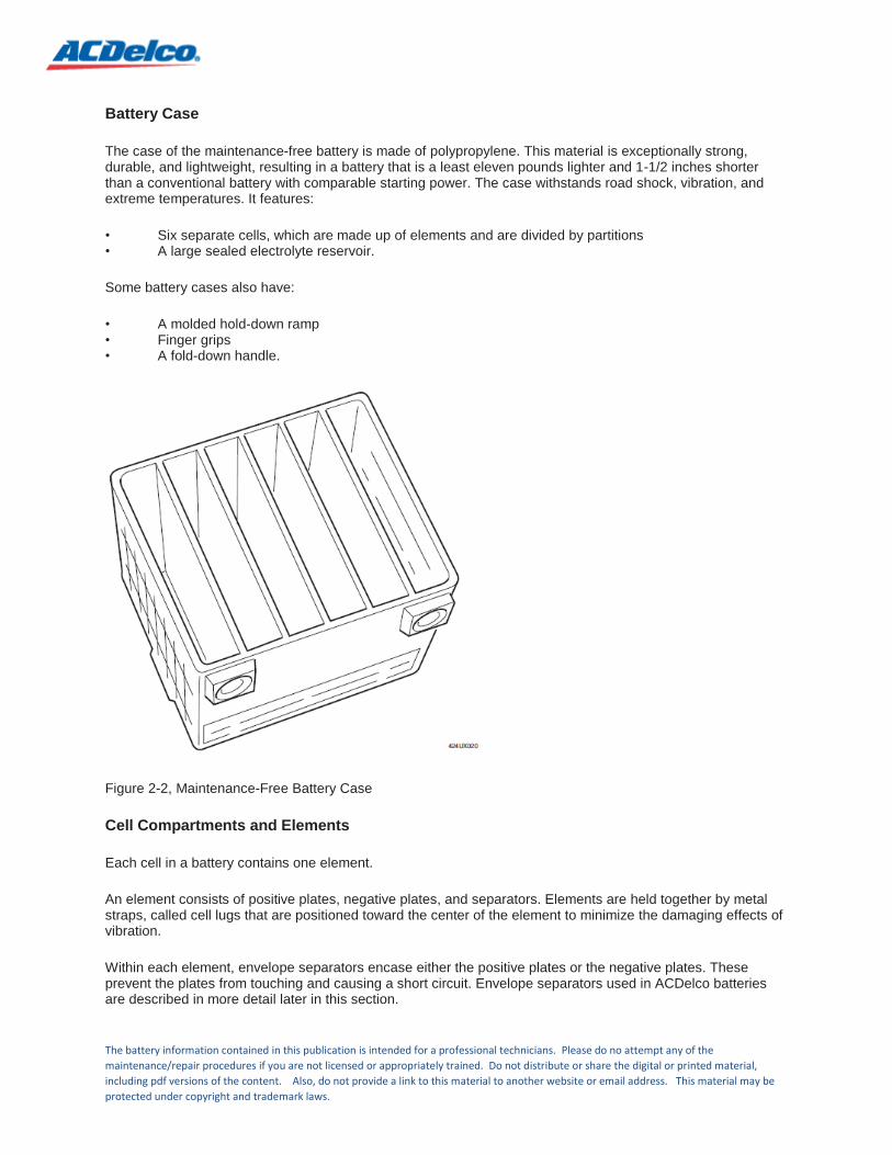
Battery Case
The case of the maintenance-free battery is made of polypropylene. This material is exceptionally strong, durable, and lightweight, resulting in a battery that is a least eleven pounds lighter and 1-1/2 inches shorter than a conventional battery with comparable starting power. The case withstands road shock, vibration, and extreme temperatures. It features:
• Six separate cells, which are made up of elements and are divided by partitions • A large sealed electrolyte reservoir.
Some battery cases also have:
• A molded hold-down ramp • Finger grips • A fold-down handle.
Figure 2-2, Maintenance-Free Battery Case
Cell Compartments and Elements
Each cell in a battery contains one element.
An element consists of positive plates, negative plates, and separators. Elements are held together by metal straps, called cell lugs that are positioned toward the center of the element to minimize the damaging effects of vibration.
Within each element, envelope separators encase either the positive plates or the negative plates. These prevent the plates from touching and causing a short circuit. Envelope separators used in ACDelco batteries are described in more detail later in this section.

The battery information contained in this publication is intended for a professional technicians. Please do no attempt any of the
maintenance/repair procedures if you are not licensed or appropriately trained. Do not distribute or share the digital or printed material,
including pdf versions of the content. Also, do not provide a link to this material to another website or email address. This material may be
protected under copyright and trademark laws.
Any number of plates can be used to form an element, depending upon the desired performance. For example, increasing the number or size of the plates increases the overall plate surface area per element. This, in turn, increases the cold cranking amps (CCA), which is the electrical current available during rapid discharge (cranking, cold starting, etc.). Generally, CCA is a measure of the interface area between the + or – plates, whereas the reserve capacity (RC) is a measure of the amount of material within a specific plate. Therefore, because each cell group has a maximum spacing, adding plates to increase CCAs (exposed square surface area) dictates reduced plate thickness and hence less reserve capacity. Regardless of the size and number of plates in an element, the open circuit voltage is limited to 2.1 volts per element.
Elements are placed in the cells of a container and connected together in series. Each cell consists of a single element. Battery voltage equals the sum total of voltages of the individual cells. Therefore, a typical car battery has six cells, each one produces approximately 2.1 volts, resulting in a total voltage of approximately 12.6 volts.
Figure 2-3, Plates and Separator
Electrolyte Reservoir
Each cell in the battery case is a large reservoir that contains electrolyte, which is a solution of 64% water and 36% sulfuric acid. Electrolyte has a specific gravity of 1.270 on a fully charged battery, meaning the solution weighs 1.270 times as much as water. 1.270 is commonly pronounced “twelve seventy”.
Anti-Vibration Designs
ACDelco employs internal devices, such as reinforcement ribs, hot-melt glue, silicone, etc., to reduce plate movements due to vibration. These devices increase battery life.

The battery information contained in this publication is intended for a professional technicians. Please do no attempt any of the
maintenance/repair procedures if you are not licensed or appropriately trained. Do not distribute or share the digital or printed material,
including pdf versions of the content. Also, do not provide a link to this material to another website or email address. This material may be
protected under copyright and trademark laws.
Molded Hold Down Ramps
Hold-down ramps are ledges molded into the battery case near the bottom. When the battery is positioned in the battery carrier, brackets provided by the vehicle manufacturer can be torqued to specifications so that they clamp down over the hold-down ramps. This secures the battery to its carrier.
Some ACDelco maintenance-free batteries have molded hold down ramps on each side of the case. Other models accommodate the over-the-top hold-down bracket on vehicles so equipped.
Finger Grips
When the top of an ACDelco maintenance-free battery is heat molded to the case, a lip is formed. This serves as a finger grip for inserting and removing a battery from its carrier, if the battery is not fitted with a fold-down handle.
Fold-Down Handle
A fold-down handle can be attached and removed from some batteries that have special handle connector buttons on the side. The handle and buttons are designed so the handle is secure when the battery is lifted, but can be removed by positioning the handle in a non-carry position and pressing on the buttons.
COVER
The cover of an ACDelco maintenance-free battery also has several significant features, including:
Permanently heat sealed to the case
Sealed terminals
Liquid/gas separator
Built-in flame arrestor vent.
Heat Seal
The cover is also made of polypropylene, the same material as the battery case. The cover is permanently bonded to the case using a high temperature and pressure process called heat sealing. The seal cannot be broken by heat or other extreme conditions encountered during the normal life of the battery.
Sealed Terminals
The negative plates of one cell are connected to the positive plates of an adjacent cell using a through-the-partition, or TTP connector. The positive plates in one end cell and negative plates in the opposite end cell are connected via lead straps to sealed terminals on the top or side of the case.
Built-In Hydrometer
The specific gravity of battery electrolyte decreases (gets lighter) as the battery is discharged. The battery’s state of charge is therefore directly related to specific gravity. The cover on some maintenance-free batteries includes a built-in hydrometer that visually shows the battery’s state of charge.
Hydrometers on Voyager Batteries
ACDelco Voyager batteries are used in marine applications. They also have a built-in hydrometer that works in much the same way as the hydrometer previously described for automotive uses, except that the Voyager hydrometer has two balls rather than one. The two balls are green and red. A red reading indicates that the battery charge has dropped below 50%.

The battery information contained in this publication is intended for a professional technicians. Please do no attempt any of the
maintenance/repair procedures if you are not licensed or appropriately trained. Do not distribute or share the digital or printed material,
including pdf versions of the content. Also, do not provide a link to this material to another website or email address. This material may be
protected under copyright and trademark laws.
Figure 2-5, Voyager Battery–Built-In Hydrometer
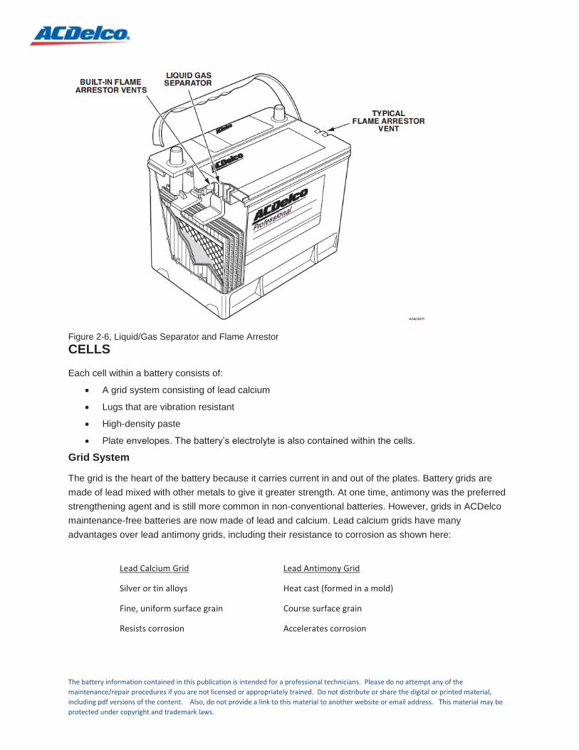
Liquid/Gas Separator
Even with a low charging rate, a small amount of gassing occurs in a battery. In an ACDelco maintenance-free battery, this gas escapes through a series of passages, called a liquid/gas separator, and vents in the cover. These have built-in flame arrestors to reduce the possibility of explosion. All these components are shown in Figure 2-6.
To escape through the vents, gas rises and passes through the liquid/gas separator, which is built into the internal surface of the cover. A safety feature in this passageway prevents electrolyte liquid from spilling out through the vents. Any electrolyte carried with the gas is trapped in the liquid/gas separator and flows back into the cells, thus practically eliminating electrolyte loss.
Flame Arrestor/Venting
A flame arrestor inside each vent keeps sparks or flame from entering the battery. This important safety feature prevents gas explosions that might be caused by external sparks.
The majority of batteries will remain as dual-vent. Some configurations requiring outside venting may be a single-vent style only.
The battery information contained in this publication is intended for a professional technicians. Please do no attempt any of the
maintenance/repair procedures if you are not licensed or appropriately trained. Do not distribute or share the digital or printed material,
including pdf versions of the content. Also, do not provide a link to this material to another website or email address. This material may be
protected under copyright and trademark laws.
Figure 2-6, Liquid/Gas Separator and Flame Arrestor
CELLS
Each cell within a battery consists of:
A grid system consisting of lead calcium
Lugs that are vibration resistant
High-density paste
Plate envelopes. The battery’s electrolyte is also contained within the cells.
Grid System
The grid is the heart of the battery because it carries current in and out of the plates. Battery grids are
made of lead mixed with other metals to give it greater strength. At one time, antimony was the preferred
strengthening agent and is still more common in non-conventional batteries. However, grids in ACDelco
maintenance-free batteries are now made of lead and calcium. Lead calcium grids have many
advantages over lead antimony grids, including their resistance to corrosion as shown here:
Lead Calcium Grid
Silver or tin alloys
Fine, uniform surface grain
Resists corrosion
Lead Antimony Grid
Heat cast (formed in a mold)
Course surface grain
Accelerates corrosion

The battery information contained in this publication is intended for a professional technicians. Please do no attempt any of the
maintenance/repair procedures if you are not licensed or appropriately trained. Do not distribute or share the digital or printed material,
including pdf versions of the content. Also, do not provide a link to this material to another website or email address. This material may be
protected under copyright and trademark laws.
Grid Corrosion
Gradual corrosion is a normal occurrence during the service life of a battery, and it is the primary enemy of the positive grid. Corrosion begins on the grid surface at grain boundary sites (places where the grain touches and bonds) and penetrates into the interior of the grid along the grain boundaries. This effect is more prevalent in batteries with coarse-grained grids.
As the grid corrodes, it is weakened because the cross-section of the grid wires is reduced. This decreases the current-carrying capacity of the grid. In extreme cases, sections of grid wires become completely severed and removed from the electrical circuit.
Corrosion takes place primarily at the positive grid, and the process is more pronounced in batteries that routinely experience overcharging.
Lead Antimony Cast Grid
Figure 2-7 shows a grid cast from lead antimony. At one time, lead antimony grids were readily available, inexpensive, and easy to cast, and for many years, provided a rechargeable battery that offered optimum efficiency and low cost.
Figure 2-7, Lead Antimony Cast Grid
Lead Calcium Grid
With the innovation of the ACDelco maintenance-free battery, calcium has since proven to be a better material to mix with lead. The lead calcium grid is substantially more resistant to corrosion as well as overcharging, gassing, water usage, self-discharge, and thermal runaway, all of which limit battery life in conventional lead acid batteries. Figure 2-8 shows a lead calcium grid.
Enhanced life Alloy
Calcium alloy is used to produce a fine grained grid to maximize corrosion resistance, increase cycle life, and reduce water consumption.

The battery information contained in this publication is intended for a professional technicians. Please do no attempt any of the
maintenance/repair procedures if you are not licensed or appropriately trained. Do not distribute or share the digital or printed material,
including pdf versions of the content. Also, do not provide a link to this material to another website or email address. This material may be
protected under copyright and trademark laws.
Plates and Paste
The plates are the active materials in the battery. The first step in making the plates is to paste a mud-like material to the grid. The paste is a mixture of lead oxide, sulfuric acid, and water. Fiber or plastic strips are often used to reinforce the plates for strength and resistance to vibration. The composition of the negative paste also contains expanders that prevent the hardened paste from shrinking and reverting to its dense inactive state. When the paste dries on the grid, the materials become a hardened plate.
During the manufacturing process, the plates are immersed in an electrolyte solution composed of sulfuric acid and water that gives them a forming charge. This charge alters the chemical properties of both plates. The process converts the lead oxide on the positive plate to lead dioxide. The same forming charge converts the lead oxide on the negative plate to sponge lead.
Figure 2-8, Lead Calcium Grid
Cell lugs
Cell lugs are connectors that attach to tabs on the grids and link one cell to another at a position above the height of the plates. Each maintenance-free battery cell has two lugs; one connects all the positive plates, and the other connects all the negative plates within the cell. The cells are then connected in series, using through-the-partition welds between the lugs of adjoining cells.
Intercell Weld
An extrusion fusion weld uses a patented lead alloy for the inter-connecting lead strap connections. Weld process parameters and corrosion resistance of the welds are optimized through laboratory and fleet testing, this ensures consistent power flow and reliability,

The battery information contained in this publication is intended for a professional technicians. Please do no attempt any of the
maintenance/repair procedures if you are not licensed or appropriately trained. Do not distribute or share the digital or printed material,
including pdf versions of the content. Also, do not provide a link to this material to another website or email address. This material may be
protected under copyright and trademark laws.
Envelope Separator
Separators are nonconductive, microporous materials that allow good electrolyte diffusion between the plates while preventing them from touching each other. ACDelco utilizes robust envelope separators that have ultra-low resistance. They are designed with a puncture resistant back web with a rib design. The envelope separators are designed to improve acid circulation allowing the battery to remain cooler, extending battery life. Separators in ACDelco maintenance-free batteries are made of polyvinyl chloride and shaped like an envelope, as shown in Figure 2-9. They are sealed on three sides.
Separators help prevent internal treeing between plates. Treeing is a condition that occurs when active material transfers from one plate, through a hole in the separator, and forms a connection to the next plate. Treeing would test as a short because the active material from one plate group forms a bridge to a plate group with an opposite charge.
Since positive plates and negative plates are placed alternately next to each other, envelope separators need only be wrapped around either the negative plates or the positive plates.
Figure 2-9, Envelope Separator
Electrolyte
Electrolyte is a solution of approximately 64% water (H2
O) and 36% sulfuric acid (H2
SO4
) that has a specific
gravity of 1.270 when fully charged. Electrolyte is used in batteries to conduct current between the positive plates and the negative plates. As a battery loses its charge, the chemical composition of the electrolyte changes and it becomes more like water. When this occurs, the electrolyte must be recharged in order to return to its fully charged state. Recharging can be done with the automotive generator or by an external battery charger.

The battery information contained in this publication is intended for a professional technicians. Please do no attempt any of the
maintenance/repair procedures if you are not licensed or appropriately trained. Do not distribute or share the digital or printed material,
including pdf versions of the content. Also, do not provide a link to this material to another website or email address. This material may be
protected under copyright and trademark laws.
BATTERY CONFIGURATIONS
Two of our most popular maintenance-free battery lines include:
Standard light-duty models, typically used for passenger cars and light trucks
Heavy-duty models, for commercial, farm, and specialized applications.
Though heavy-duty batteries are generally larger than the standard models. The design features discussed to this point are common to both lines. The features listed below, however, can vary from model to model.
Positive and negative Terminal Identification
Most maintenance-free batteries have “+” and “–” terminal designations molded into the battery case, as well as covers for both terminals. These features ensure the terminals are permanently identified and protected.
Terminal Designs
Terminal designs vary depending upon vehicle application. Common terminal configurations are:
Tapered top
Side
Dual
L
Stud
Stud/post
Tapered Top Terminal
Tapered top terminals are designed to industry standards, and most cables built in North America fit this type of terminal. The positive terminal is slightly larger than the negative posts to minimize the danger of connecting the cables in reverse polarity.
Side Terminal
Side terminals are molded into the side wall of the case, near the top. Cables are attached to the terminal via a special adapter that threads into the terminal. When tightening the bolt, it’s important to follow the manufacturer’s recommended torque value to avoid damage.
Dual Terminal
A dual terminal battery has terminals on the top and the side of the battery. This allows cables to be easily at-tached to either pair of terminals and the battery to be easily installed in a greater variety of vehicle applications.
L Terminal
The L terminal is used on many European car batteries and special applications, such as marine. The cable is attached to the terminal by a bolt and wing nut.

The battery information contained in this publication is intended for a professional technicians. Please do no attempt any of the
maintenance/repair procedures if you are not licensed or appropriately trained. Do not distribute or share the digital or printed material,
including pdf versions of the content. Also, do not provide a link to this material to another website or email address. This material may be
protected under copyright and trademark laws.
Stud Terminal
The stud terminal is another top mount design that features a threaded stud onto which a wing nut can be tight-ened. The stud terminal is typically found on heavy-duty batteries.
Stud/Post Terminal
The stud/post terminal is a design that features a stainless steel stud and an SAE post sealed to prevent leaks. The stud/post terminal is typically found on marine batteries.
Figure 2-10, Various Battery Terminal Configurations
Unique Features for Heavy-Duty Batteries
As previously mentioned, heavy-duty maintenance-free batteries are constructed with many of the same features as the standard models, but there are a few notable differences.
Stainless Steel Terminals
Heavy-duty battery terminals are made of stainless steel. Connecting the cables to the terminals using the proper torque specifications provides an airtight seal, eliminating corrosion on the current-carrying surfaces. This ensures optimum electrical performances and eliminates the need for periodic maintenance and cleaning.

The battery information contained in this publication is intended for a professional technicians. Please do no attempt any of the
maintenance/repair procedures if you are not licensed or appropriately trained. Do not distribute or share the digital or printed material,
including pdf versions of the content. Also, do not provide a link to this material to another website or email address. This material may be
protected under copyright and trademark laws.
Epoxy Anchored Terminals
These terminals are sealed to the battery using a strong epoxy compound. This feature further resists the damaging effects of vibration common to heavy-duty applications. The elements rest on the bottom of the case, and there are no sediment chamber ribs to cause vibration wear.