maintenance and repairs manual for private micro …
TRANSCRIPT

MAINTENANCE AND REPAIRS MANUAL
FOR
PRIVATE MICRO HYDRO-POWER PLANTS Prepared by
Development and Consulting Service
P.O. Box: 8, Butwal, Nepal
Revised by Dr. Anwar A. Junejo
International Centre for Integrated Mountain Development
(ICIMOD)
Kathmandu, Nepal
1998
Printed by – Alternate Hydro Energy Centre, U.O.R. Roorkee, India

Preface This manual has been prepared as one of a series of five for various groups of technicians and professionals engaged in design, survey, feasibility studies, manufacture, installation management, operation, maintenance and repairs of private/community based microhydro power (MHP) installations in the Hindu Kush-Himalayan Region. The main reason for preparing these manuals was the felt and stated need of such implementers groups for whom opportunities for adequate training or advisory back-up were lacking; but are now recognized to be a key ingredient for success. This is mainly because such schemes are designed, installed and operated by people whose capacities in this respect are not up to the desirable mark. The current manual is aimed at managers and operators who have to carry out maintenance and minor repairs and also to organize major repairs in the remote and under-developed mountain areas. It is hoped that this manual would provide some assistance to such professionals as a reference document. Keeping in view the lower educational qualifications of managers and operators, an attempt has been made to keep the contents of the manual simple. However, in such cases there always has to be a trade off between the depth of knowledge which decides its usefulness and simplicity which results in its use by many less qualified practitioners. An attempt has been made here to achieve this trade off. All the manuals including this one have been prepared as a specified component of the project titled “Capacity Building for Mini- and Micro-hydropower Development in the Selected Countries of Hindu Kush-Himalayan Region-Phase II”. The project is generously funded by NORAD and implemented by ICIMOD. The first draft of this manual was prepared by Development and Consulting Services (DCS), Butwal, Nepal. Later, it was extensively revised by Dr. A.A. Junejo, the project Coordinator of MMHP project with the help of field staff of DCS; which did a very good job in providing the necessary information in one document and identified many damage mechanisms and reparis methodologies. The revision is based on recommendations of the Consultative Meeting of regional and International Experts which reviewed all the draft manuals in February 1998. ICIMOD is grateful to DCS and its field staff for their inputs and hard work. This and other manuals would be sent to the national focal agencies for modification (if necessary), translation and publication in India, Nepal and Pakistan; and would be distributed to the prospective deserving users and beneficiaries including some relevant institutions. This is a first attempt to produce and publish manuals such as these for the user-groups mentioned earlier; therefore, there should be many possibilities for improvement. From this point of view, comments and suggestions from the experts, institutions and users are very welcome and would be considered during the revision of these manuals.
Dr. Anwar A. Junejo Coordinator, MMHP Project
ICIMOD
Deleted: Page Break

TABLE OF CONTENTS Page
CHAPTER 1: Introduction
1.1 About this Manual
CHAPTER 2: Maintenance and Repair of Civil Works
2.1 Weir or Partial Dam
2.2 Intake
2.3 Power Canal
2.4 Desilting Basin
2.5 Break Pressure Tank
2.6 Forebay
2.7 Tailrace
CHAPTER 3: Penstock and Allied Structures
3.1 Penstock Pipe
3.2 Support Structure for Penstock
3.3 Expansion Joint
CHAPTER 4: Maintenance and Repair of Electro-mechanical Equipment
4.1 Valves
4.2 Turbine
4.2.1 Crossflow Turbines
4.2.2 Pelton Turbines
4.2.3 Tapered Locking Sleeves
4.2.4 Bearing fitted with Tapered Adapter Sleeves
4.2.5 Checking the Bearing Damage
4.3 Power Drive Systems for MHP Plants
4.3.1 Couplings for Direct Drives
4.3.2 Belts and Pulleys
4.4 Generators
4.5 Controls and Instrument Panel
4.5.1 Instruments for Schemes without Load Controller
4.5.2 Instruments for Schemes having Load Controller
4.5.3 Protection

CHAPTER 5: Maintenance and Repair of Transmission Lines
5.1 Transformers
5.2 Transmission Lines
5.3 Lightning Arresters
CHAPTER 6: General Suggestions about Repairs
6.1 Maintenance Check List and Schedule
6.2 Suggested Tools to be Stocked at MHP Plant
6.3 Maintenance of Tools

CHAPTER I
Introduction
Energy needs of the people of Hindu Kush-Himalayan (HKH) region are not being met adequately because the traditional resources such as fuel-wood are dwindling fast and more modern resources are difficult to provide due to many constraints. The per capita energy usage in these areas is very low; therefore, it cannot support initiatives to improve living conditions, create employment and income enhancement opportunities and contribute towards overall development such as infrastructure development. Therefore, suitable and reliable energy resources need to be developed and implemented in such areas, keeping in view their specific features which are significantly different from the plains or even hilly areas nearer the plains. Tue level of development, for example, is very low, the people are poor, access is difficult, population is scattered and awareness and know-how about the machinery is almost nonexistent. To meet the energy needs of such areas the energy sources and systems must be reliable and preferably such that local population can easily manage them and adopt them. Micro-hydropower (MHP), which builds upon traditional technology of water wheels (Ghattas or Gharats), is now recognised to be the most suitable, environment-friendly and even leastcost option for many such areas. Private, community-based and decentralised MHP installations. are now meeting the energy needs of many mountain areas in China, Nepal and Pakistan to a significant extent. While appropriate support arrangements have been put into place in China, they are severely inadequate in Nepal and Pakistan. As clearly recognised during various meetings, consultations and field studies, appropriate and adequate institutional support and interventions need to be designed and provided to different professionals analyzed in various aspects of MHP implementation; without which the performance and viability is unlikely to be satisfactory. This is because such MHP schemes, are designed, manufactured and installed indigenously and owned, managed, operated and maintained by the local people of the remote mountain areas. The identified interventions mainly concern improvement of quality and performance which can be achieved through development and dissemination of training programmes, manuals, standards and guidelines, back-stopping and advise to the managers/operators and finally, proper maintenance and repair systems for such plants. In this regard, ICIMOD has taken the initiative and attempted to design and implement quality training programmes and prepare and disseminate appropriate information manuals on various aspects of MHP implementation including site survey and layout, design and manufacture, installation, management and operation and repairs. In all, five such manuals have been prepared for the technicians and owner-managers engaged in implementation and operation of such plants, These activities are part of a project designed and implemented by ICIMOD and financially supported by the Norwegian Government.
1.1 About this Manual

This manual is mainly prepared for the owner-managers and operators of private MHP plants, who hove to mostly rely on themselves or some local technicians to carry out identification of a manufactures and subsequent repairs. Obviously, these owners or operators can not carry out properly all the repairs due to lack of expertise or knowledge, proper tools and instruments and workshops and the allied equipment. Another impediment is the wide variety of equipment and different designs that exist in the HKH region. In Nepal alone, three distinctly different designs of cross flow turbines are being produced by the manufacturers due to lack of agreed standards or any form of supervision or co-ordination. Nevertheless, most design concepts and many important components are the same; therefore, an attempt has been made here to describe methodology for diagnosing and assessing the malfunction, deciding about the course of action for repairs and actually carrying out many basic repairs, including assembly and disassembly. It is accepted that many repairs would have to be referred to properly qualified and equipped technicians and workshops; thus some suggestions for repairs at these places have also been included. One of the keys to reliable operation is routine preventive maintenance, ie, regular inspection, lubrication, cleaning, replacing worn items and responding to concerns identified during inspections immediately rather than waiting for machinery to break down before taking action. If minor repairs are not carried out soon enough, the plant may break down completely, resulting in significant additional cost, loss of income due to delays in repairing the affected part and may be more damage to other more expensive parts. One of the purposes of this manual is to item wise recommended appropriate preventative maintenance for a typical MHP plant and to give details about how to implement it. It is important that manufacturers' maintenance schedules and the periodic checks described in this manual are, carried out if installed machinery is to give reliable service for a long time. However, detailed daily or weekly maintenance is not covered in this manual. Even though a preventive maintenance scheme may be carefully implemented, occasional breakdowns will still occur. Sometimes after repairing or replacing parts of the plant, difficulty may be experienced in getting the new component to function correctly. To assist in problem solving, a number of common problems encountered in MHP plants are also listed in this manual, along with their causes and recommended corrective action. In some installations agro-processing machines such as oil expellers, rice hullers, flour grinders, etc., are also driven by the MHP plant (either directly via an intermediate shaft not needing electrical power, or through electric motors). This manual does not specially cover maintenance and repair of driven end use machinery other than the electric generator. Basically, the information provided in this manual is applicable for plants having capacity up to 100 kW. However, plants larger than 50 kW usually incorporate more safety related equipment and also need sophisticated tools and workshop facilities for repairs. Therefore, this manual is more relevant for the smaller plants having less than 50 kW, capacity. In fact, most of the private/community based plants in Nepal, Pakistan and India fall within this range, therefore this manual should be beneficial for the more than 1000 such plants.
CI-IAPTER 2 MAINTENANCE AND REPAIR OF CIVIL WORKS
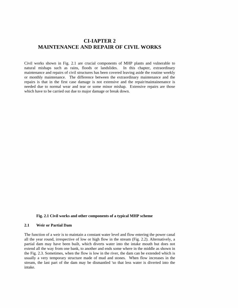
Civil works shown in Fig. 2.1 are crucial components of MHP plants and vulnerable to natural mishaps such as rains, floods or landslides. In this chapter, extraordinary maintenance and repairs of civil structures has been covered leaving aside the routine weekly or monthly maintenance. The difference between the extraordinary maintenance and the repairs is that in the first case damage is not extensive and the repair/maintainenance is needed due to normal wear and tear or some minor mishap. Extensive repairs are those which have to be carried out due to major damage or break down.
Fig. 2.1 Civil works and other components of a typical MHP scheme 2.1 Weir or Partial Dam
The function of a weir is to maintain a constant water level and flow entering the power canal all the year round, irrespective of low or high flow in the stream (Fig. 2.2). Alternatively, a partial dam may have been built, which diverts water into the intake mouth but does not extend all the way from one bank, to another and ends some where in the middle as shown in the Fig. 2.3. Sometimes, when the flow is low in the river, the dam can be extended which is usually a very temporary structure made of mud and stones. When flow increases in the stream, the last part of the dam may be dismantled 'so that less water is diverted into the intake.

Construction materials used in a weir can be of different types; eg, stone in which case, dressed stone is used on the wall face while ordinary stones can be used inside the weir. Alternatively, a gabion or cement-stone masonry wall may have been constructed to make it more strong. Concrete weirs are rarely used for MHP plants. The partial dam, on the other hand, is almost always constructed from mud mortar and stone because it is really a temporary structure and it can be washed away, removed partially or fully or it can be extended as per the requirements of the flow in the canal.
Fig. 2.2 A typical stone masonry weir
Mostly, damage to the weir or a partial dam is caused by flood or high flow in the river which can break or partially wash them away. Sometimes, big boulders are carried or rolled by high flows which may hit the weir and damage even more permanent structures such as an stone i-masonry weir, which otherwise would not be affected by floods. Third source is silt carried in water, or caused by an upstream landslide. Silt deposits would normally raise the level of the weir without breaking it.
Fig. 2.3 A partial temporary dam to divert flow

The damage caused by such sources is likely to be in the form of breaking of the weir partially or fully or raising of height due to deposed silt. The partial dam may be washed away completely which is a temporary structure anyway. Sometimes, the weir or the temporary dam may leak which needs to be plugged. Before commencing any repairs, it is necessary to assess the damage through inspection and different checks. For example, a gabion weir should be inspected for the drainage to side of the gablon, change in the shape or breaking of wires. Some forting material might also have collected around or above the weir; which would have to be removed. Such inspections, therefore, are necessary to assess the damage and also to decide what sort of repairs are needed, depending upon the type of structure as well as the extent and type of damage. To repair a gabion weir, first remove any foreign material including silt, leaves, sticks, etc, on the top or around it, then open the wire mesh at the top. Remove all the stone masonry which has bulged or eroded and start reconstruction using dressed stones on the outside and normal stones at the inside as if it was being constructed anew. The wire mesh can be repaired by adding and/or enmeshing similar wire to the original mesh and then closing it at the top by twisting the two wire-ends together and bending them to reach level of the surface. In case of dry stone or cement stone masonry weir also, remove all the foreign materials from the sides as well as the top of the weir. Then, remove the damaged part of the structure in the masonry and start reconstruction with the same materials as before. In case of a mud mortar and stone masonry structure, specially the partial dam, the repair of the damage is ordinary and simple; ie, remove the damaged portion and rebuild using the same materials as originally used.
2.2 Intake
The main function of the intake is to allow only rated flow into the headrace canal and, as far as possible, to block entry of undesirable solid materials such as stones or wood sticks. For this purpose, either a coarse trash rack or cross-bars are provided at the intake mouth (Fig 2.4). Usually, three types of intake are used for MHP schemes. In most cases, it is must an opening constructed in the side of the stream loading to the canal. The down-stream end of the opening may be extended in the form of a- partial dam described earlier. In another case, a proper wall may be constructed in which the intake mouth would be in the form of a rectangular window (Fig. 2.4 b). In the third case, a pipe may be directly extended up to the middle of the stream where the water may be deepest, and the pipe mouth remains submerged all the time. When the intake is just an opening in the wall, the side walls adjoining the intake area are properly constructed from masonry of dry stone or from stone masonry and cement mortar. The sources of damage for the intake structure are again mainly high floods and flows and boulders, logs or other such heavy objects transported by flow. The third possible source is deposit of silt at the intake mouth, which would reduce the flow. Additionally, landslides may either damage the structure or block it. Silt or other solids may also block the pipe mouth if a pipe intake has been used.
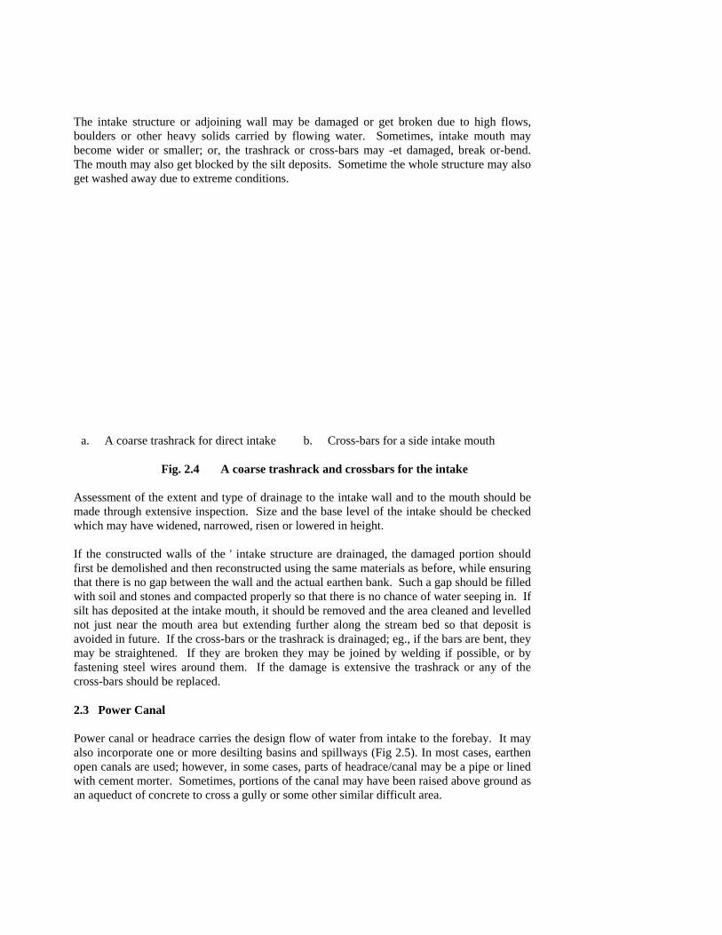
The intake structure or adjoining wall may be damaged or get broken due to high flows, boulders or other heavy solids carried by flowing water. Sometimes, intake mouth may become wider or smaller; or, the trashrack or cross-bars may -et damaged, break or-bend. The mouth may also get blocked by the silt deposits. Sometime the whole structure may also get washed away due to extreme conditions.
a. A coarse trashrack for direct intake b. Cross-bars for a side intake mouth
Fig. 2.4 A coarse trashrack and crossbars for the intake Assessment of the extent and type of drainage to the intake wall and to the mouth should be made through extensive inspection. Size and the base level of the intake should be checked which may have widened, narrowed, risen or lowered in height. If the constructed walls of the ' intake structure are drainaged, the damaged portion should first be demolished and then reconstructed using the same materials as before, while ensuring that there is no gap between the wall and the actual earthen bank. Such a gap should be filled with soil and stones and compacted properly so that there is no chance of water seeping in. If silt has deposited at the intake mouth, it should be removed and the area cleaned and levelled not just near the mouth area but extending further along the stream bed so that deposit is avoided in future. If the cross-bars or the trashrack is drainaged; eg., if the bars are bent, they may be straightened. If they are broken they may be joined by welding if possible, or by fastening steel wires around them. If the damage is extensive the trashrack or any of the cross-bars should be replaced. 2.3 Power Canal
Power canal or headrace carries the design flow of water from intake to the forebay. It may also incorporate one or more desilting basins and spillways (Fig 2.5). In most cases, earthen open canals are used; however, in some cases, parts of headrace/canal may be a pipe or lined with cement morter. Sometimes, portions of the canal may have been raised above ground as an aqueduct of concrete to cross a gully or some other similar difficult area.

The usual sources of damage to the canal are excessive flow, depositing of silt, landslides, rain water coming firm up the '-'II, or sometimes animals and humans. The damage may be in the form of leakage from the pipe or canal, or, blockade due to silt or other foreign materials. The banks or the bed may be eroded which may eventually result in the part of the canal falling down. The pipe may be blocked or may have been damaged and leaking. Inspection of the power canal to assess the extent of drainage should not just be confined to the canal or pipe but also the area around them including the upper and under-sides and signs of leakage, slip or other type of degradation ,lust be assessed. All of the affected area would have to be repaired in an appropriate way to avoid a serious break down in future depending upon type and extent of damage.
Fig. 2.5 Main components of a micro-hydro scheme including power canal and desilting basins
If there is a leakage from the canal', water should be stopped at the intake and the damaged area inspected to determine whether a retaining wall underneath the damaged portion was needed; or, whether it was necessary to use other better masonry system for the wall construction; eg., cement-stone masonry. Usually, a larger portion of the bank beyond the damaged portion should be removed and then reconstructed from the same or better materials, such as cement-stone or mud-stone masonry. If there is a very small crack in a stone masonry or concrete wall, it can be blocked with the help of bitumen. If large amount of silt has deposited at the bed of the canal, it should be removed in such a way that the original level of the bed is maintained. If a portion of the canal bank has collapsed; it is necessary to dig deeper into the mountain side until a more stable soil or surface is reached. Then, stone soling in horizontal direction should be constructed first at the bottom, followed by a slopping stone or gabion wall until the canal level is reached (Fig 2.6). The space between the mountain side and the wall should be filled with stone and earth in layers (- 300 mm thick) and compacted well. If a landslide has occurred on the slope above the canal and damaged it; then also, a larger portion of the canal extending beyond the damaged area should be dug out to reach a firm base. Stone soling should be constructed at the base followed by the canal wall as described earlier. Sometimes, a landslide on the upper side of the canal might destroy the canal and the supporting underneath area completely. In that case, construction should be started from down below at a firm ground using stone soling (about 3 meters below) as described before. A retaining wall above the canal should also be built to stablise the mountain slope. If a portion of cement-stone masonry canal has been damaged or slipped down either due to a landslide on the upper side or erosion of the Linder-side; then more care needs to be taken in rebuilding the canal. Stone soling of much higher thickness should be provided at the base to support more weight. Construction of the retaining wall and canal may then be carried out as described before.

Fig. 2.6 A gabion or masonry retaining wall If a passageway for flow of rain water over the top of the canal exists, then it should also be cleaned by removing stones or other debris to keep it functional. Otherwise, the flow may be blocked and may enter the canal. If a pipe has been used as headrace, it may get blocked with 'It. For example, if a break-pressure tank is damaged and that end of the pipe has been closed, then the silt already present in water would deposit in the pipe. This deposit can be removed by force flushing, or by inserting a long wooden pole in the pipe to scrape the silt; but care must be taken to avoid damage to the pipe during this operation. Provision of adequate slope at the time of design and installation of such pipes would normally not allow depositing of silt. An unusual type of damage was reported in Nepal, where a stone entered the HDPE pipe headrace and got stuck at the lip of the joint between two pipe lengths. It was very difficult to determine the location of the blockage. Thus, a simple technique was deviced. A heavy and smooth piece of steel was tied to a rope and was allowed to slide in the pipe from the top until its reached the blocked location and stopped. The length of the rope was measured and in this way, the point of blockade was located. The pipe was cut there and stone was removed. If a large crack has developed in a HDPE pipe, the best way is to cut the cracked portion and insert and join an equivalent new piece. However, if the crack is small then the simple method would be to wrap a piece of rubber around the crack and use one or more screw clamps to keep the rubber in place to stop the leakage. 2.4 Desilting Basin The function of the desilting basin is to remove silt or other heavier suspended particles carried by the flowing water. This is done by slowing down the speed of water and making it calmer so that heavier particles settle at the bed. Desilting basins are usually constructed using cement stone masonry and the surface is properly plastered. Width of a desilting basin is between 3 to 5 times the width of the canal and the length is about 2.5 times it's own width. The sources of damage for desilting basin are landslides, floods or flows carrying excessive silt, unstability of the ground and so on. In most cases, damage is in the form of filling up of the basin due to silt or debris, leakage which means cracking up of plaster or masonry, or its sinking because of the unstable ground underneath. To repair leakage, if the cracks in the plaster are small, molten bitumen can be used to plug such cracks. Alternatively, rich cement mortar (1:2 or 1:3) may be used for closing these cracks. Third method is to re-plaster the affected area if the damage is extensive. But before replastering the damaged plaster and the masonry underneath should be removed by chiseling. If silt deposits have remained in the basin for a long time and dried and hardened, it may be difficult to remove it just by flushing. Then, the usual method is digging it out using a showel. 2.5 Break Pressure Tank Break pressure tank is constructed when HDPE or other types of pipe are used as headrace. In order to avoid use of a very thick pipe to withstand higher pressure, a break pressure

tank is provided at an appropriate location, where water comes out of one pipe at atmospheric pressure, and enters another. It is a very small tank, about 1 in or so high and is more or less constructed same way as the forebay, using cement-stone or cement brick masonry. It is properly plastered both on the inside as well as outside. The sources and type of damage in this case are similar to those of forebay. The tank may subside, or may be filled with debris or silt; which needs to be cleared. Sometimes, it may develop cracks which have to be plugged. Since the inside area is small (less than 1 m2), getting inside and plugging leakage and removing debris may be difficult but it can be done by showelling. 2.6 Forebay Forebay is the last open link between the canal and the closed penstock pipe and it's function is to facilitate flow from an open system into a closed one. At the same time, the trashrack removes the remaining floating debris from flowing water. Sometimes, a desilting basin may also have been incorporated in the forebay so that remaining amount of the silt is also removed at this stage. Mostly, the forebay is constructed by using cement-stone masonry or cement-brick masonry and is properly plastered (Fig 2.5). Therefore, it is a fairly permanent structure; and it normally does not break. It also does not need serious maintenance. Damage to the forebay may be caused by landslides or falling boulders from up the hill, by floods or excessive rain water. Unstability of the ground on which it was constructed in first place may also cause sinking and cracking. The damage my be in the form of cracks resulting in leaks, or sinking which may again cause cracking and leaking. Third possibility is excessive accumulation of silt or some other materials which can not be removed by normal flushing. As always, it is necessary to inspect the whole area surrounding the damage, especially, if the walls have cracked and there may be a posse stability of further disintegration of the structure. If this has happened, then it is a serious case and the whole forebay structure should be dug up and reconstructed. If cracks are small, say, less then 3 mm wide, then they can be plugged either with molten bitumen or by rich cement mortar. However, if larger cracks existed then the damaged plaster and masonry underneath should be cut or scraped and replastered with cement mortar. If the cracking is the result of sinking or land slip and the sinking is considerable, say 10 mm or more; then the best way is to dismantle and reconstruct the forebay structure after the unstable soil has been removed and firm ground or rock is reached. Stone soling should be provided at the base and retaining walls constructed as described earlier in section 2.3. It should be possible to remove small amounts of silt deposits or debris by flushing 2 or 3 times. However, if the amount of debris is quit large; say, caused by a landslide, then it has to be removed by showelling. sometimes, a leakage may develop around the neck of the penstock where it enters the forebay. This normally happens due to movement of the penstock and therefore, the interface between the steel pipe and forebay masonary leaks. In such a case, bitumen may be used to fill the crack. Alternatively, a small recess may be formed by chiseling around the penstock mouth and a small piece of rubber be forced into it by the help of a screwdriver or by chisel so that it becomes a force fit. 2.7 Tailrace

The tailrace carries water exiting from the turbine, back to the river and part of it is located inside the Powerhouse. Usually the tailrace is relatively short and on a plane ground where likely hood of serious damage is minimum. Inside the powerhouse tailrace is usually built from stone masonry and properly covered by a RCC or stone slab. Outside the powerhouse, it is an open channel, usually an earthen one. However, in some rare cases, if the area outside the powerhouse is fairly expensive, say an irrigated cultivated land; then it may have been constructed using cement-stone masonry in order to prevent any leakage to the surrounding area. Sources of damage to the tailrace may be sinking of the ground; or if the slope of tailrace is high, then erosion. Damage may be iii the form of leakage or increased width or depth due to subsidence or erosion. In some cases, it might have got filled by the debris of a landslide, or due to collapse of the banks. In case of the channel having become deep, it needs to be filled properly and covered by stone pitching; whereby the ground would first be filled and compacted; then thin stone slabs should be placed on the top so that the surface becomes hard and durable towards erosion. Pitching should be provided on the whole inner surface; the bed as well as the sides. If done properly, stone pitching can also stop the leakage. Sometimes in an earthen canal a hole may have been dug by some rodent. In such a case, the hole must be located and the surrounding area dug say about 300 mm deep, then refilled and compacted to plug the hole. If the tailrace has been filled by debris it can be re-du(t by showelling.

CHAPTER 3 PENSTOCK AND ALLIED STRUCTURES
3.1 Penstock Pipe Penstock carries water from forebay, which is an open tank, to the nozzle of the turbine at high velocity and under pressure (Fig. 3. 1). Thus considerable pressure may develop within the penstock near the lower end. Penstock is usually made from mild steel and equal lengths of pipe having flanges on both sides are bolted together. Unflanged pipe lengths can also be welded at the site if facilities existed. Penstock can also be made from HDPE pipe for low head applications.
Fig. 3. 1 A typical penstock installation with support structures The damage may be caused by falling rocks, corrosion, sinking of the support structures; by people, misalignment at the time of install-.'Lion, landslides or even due to freezing of water inside the pipe. The damage may be in the form of cracks and leakage, removed or broken bolts, formation of rust, bending and so on. Inspection of the damage should be carried out, to pin point the exact location and size of the crack causing leakage. Bending of the pipe should also be checked which may be the result of sinking of support piers and anchor blocks. The penstock surface should be inspected to determine removal of the paint, extent of rusting, cracking, or other such damage. In addition, the pipe should also be inspected to check whether it has been dented or deformed; it may have become oval, for example. In order to prescribe proper repairs, the nature as well as the source of the damage should be determined before undertaking any repairs. For example, in case of a leaking pipe, it needs to be a certained whether the leakage is due to a worn out gasket, loose or missing bolts, cracks at the weld, or, holes formed by some other source, such as a falling stone. In all these cases, different types of repairs would be needed. If a joint was leaking, then probably the gasket is worn out. Thus the joint has to be opened by removing the bolts and the gasket replaced. Usually, the same size and type of gasket (flat rubber gasket or o-ring) should be installed. If the leakage is caused by a crack, the area where the crack or a hole has appeared must be cleaned properly removing all the rust or paint with the help of emery paper and then welded. Before welding, water from the pipe should be removed and the surface properly dried. welding can only be done at the site if welding equipment (whether electric welding or gas welding) could be made available there; which is usually difficult. Therefore, if it is a large crack, then that section of the pipe should be removed and taken to a place where proper welding can be carried out. If, luckily, a crack or a hole is small, then it can be plugged by wrapping a rubber sheet around the pipe and fixing it in place with the help of clamps as described earlier. This can only be a temporary arrangement and welding may still be necessary since it is likely that the crack would expand. If some bolts are loose or missing, they must be tightened or replaced as early as possible with new ones of same material and same size. If the leakage still persists, the gasket should be changed. If this also does not work, then the alignment of the penstock may be out or the gap between the flanges may have

become too large; the expansion joint may be checked, adjusted or repaired. If there is a small bend or a dent in a pipe caused by a falling rock (say), it may be left unrepaired after ascertaining through inspection that the damage (especially a bend) was not causing severe stress to the joints. The surface may be polished and repainted to avoid rusting. The only different type of damage which may be caused to HDPE penstock pipe, is its cracking and the repair methodology. Cracks may appear due to excessive bending or due to some manual sources, such as cattle walking over it. In this case also, if the crack is very large it should be repaired in the same way as described earlier; ie, the cracked portion be cut out and new piece fitted by heat welding. Small cracks may be plugged by using rubber sheet and clamps. The plate to melt the edge of HDPE pipe can be heated by using charcoal or even good quality firewood. The plate must be heated to 220' C, which can be checked by using thermo chrome chalk.' When plate is marked with this chalk the mark may turn from white to brown within 5-10 seconds if the temperature is right, If the colour changes in less then 5 seconds, then the plate is too hot; if it changes too late, ie, after 10 seconds then it is too cold and must be heated again. 3.2 Support Structures for Penstock Support structures include support piers which allow some axial movement of the penstock; whereas, anchor blocks do not allow any kind of movement in any direction. Support piers are mostly made from cement-stone masonry and plastered with cement mortar; while anchor blocks are almost always made from concrete (Fig. 3.2). However, in case of some cheap plants the support piers may also be made from dry stone masonry or some other cheaper materials. Damage to support structures may be caused by subsidence of land mass, landslides, water standing in the vicinity of foundations, unstable ground, and so on. The damage may be in the form of sinking or erosion of the base, sliding of whole structure down the hill, breaking or cracking of the plaster and masonry, etc.
Fig. 3.2 Anchor block near the powerhouse The damage must be inspected and assessed properly. Usually, the cracking or breaking of the masonry may be repaired by removing the damaged sections and reconstructing them. However, in case of sinking, the whole structure should be dismantled including the foundation and rebuilt after ensuring that the original levels at the points of supports for the penstock are reached. For this purpose, some temporary supports to the penstock should be provided near the construction points before dismantling. The area must also be inspected for any drainage problems; for example, water may be accumulating in that a.-ea. Therefore, some drainage channels should be built and the ground leveled properly so that adequate slope exists and water drains away quickly from the structures. 3.3 Expansion Joint

The main function of the expansion joint is to allow axial movement of penstock pipe which is usually caused by changes in the ambient temperature. This movement is necessary because otherwise undue stresses would be induced in the penstock if the natural expansion is not allowed to take place. The most common type of expansion joint comprises of two pieces and is bolted (or welded in some rare cases) to the flanges of penstock pipe lengths (Fig. 3.3). When the pipe expands or contracts, one piece of the expansion joint slides over the other and the leakage is prevented by inserting a suitable sealing packing, which can be compressed to stop leakage with the help of bolts provided in a stay ring.
Fig. 3.3 A bolted type expansion joint
Damage to the expansion joint may be caused by misalignment which may occur due to sliding, or bending of anchor block or even lateral movement of support piers, jamming of the moving parts due to rusting or over-tightened packing. Sometimes, axial movement of the pipe can also cause serious damage to the expansion joint especially when the gap between the two pipe ends is already very large and there is a possibility that one piece of expansion joint may slide out of the other. The main type of damage is jamming due to rusting, misalignment or damaged seating packing resulting in leakage, loss or bending of the stay ring bolts, etc. Sometimes, if the gap provided between the two penstock pipes ends at the time of installation was less than what was needed, then the two ends of pipe inside the joint may touch or even press against each other when the pipe expands, causing damage not only to the expansion joint but also to the anchor blocks. If the expansion joint has jammed, it should be disassembled, the mating/sliding surfaces scrubbed with emery paper or wire brush and greased. The under-side of the packing which slides over the pipe end should not be greased. If the expansion joint is leaking then extra turns of the packing rope of same size may be added. Sometimes, the leakage can be stopped by just tightening the bolts of the stay ring which would compress the packing further and stop the leakage. If the packing is badly worn out, it should be replaced with- a new one after dismantling the joint and cleaning the surfaces.' Usually, a jute rope having square cross-section is used as packing material. If extra packing is to be added or replaced, the stay ring should be , removed and the original packing taken out and new packing inserted after cleaning the surfaces. The number of turns of this packing would depend upon the pipe length that it need s to cover (usually between 20-30 mm). The stay ring which compresses the packing into place and prevents leakage, should be reassembled and the nuts and bolts tightened only just enough to stop the leakage. Over-tightening can damage the packing and jam the expansion joint. Sometimes, the gap between the two ends of penstock pipe within the expansion joint may need to be adjusted. If the gap is less than what it should be, ie, it needs to be increased; then remove the expansion joint and cut a suitable length, of the inner pipe over which the packing rests. If the gap needs to be decreased, then this is a difficult process because that would mean adjusting the whole length of the penstock pipe which can only be done by dismantling it completely and replacing a length with especially made longer piece. However, if the adjustment is only of the order of say 5-10 mm; then one or more rings can be added at

various flanges of the pipe lengths down-stream of the expansion joint and gaskets provided on both sides of these rings. If misalignment exists between the two pipe ends; a lot of damage may result, not only to the expansion joint but also to anchor blocks or the whole penstock pipe. Thus it is necessary to remove this misalignment as much as possible. Sometimes, it can be removed by putting some kind of packing between the penstock pipe and the support pier saddle in order to raise the penstock at that point. Sometimes, the groove in the pier may be deepened by chiseling to lower the level of penstock pipe at that point. Sometimes, if it is really necessary, two (or more) pipe lengths can be actually bent slightly to adjust the misalignment; but this would be a very tricky and precision work which should only be undertaken in properly equipped workshop where the extent of the bending can be controlled and measured. For most of the repairs it is usually necessary to dismantle the expansion joint that means separating it from the pipe ends by removing the bolts at the flanges and the stay ring and separating the two parts. The reassemble, clean and grease the mating/sliding surfaces, change the packing and tighten the bolts slightly. Assemble the stay ring in position and fit one part into the other, pushing it fully in (minimum gap). The assembly of the expansion joint is now complete and can be fitted to the flanges of the two penstock pipe ends. Adjust the length as necessary to reach the two flanges and tighten the bolts of the flanges after fitting new gaskets. Tighten the bolts of stay ring to achieve required compression of the packing. Fill the penstock with water and tighten the bolts of the stay ring compressing the packing until there is no leakage from the joint.
CHAPTER 4
MAINTENANCE AND REPAIR OF ELECTRO-MECHANICAL EQUIPMENT
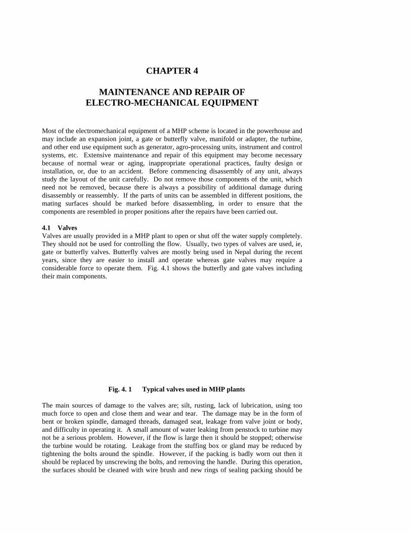
Most of the electromechanical equipment of a MHP scheme is located in the powerhouse and may include an expansion joint, a gate or butterfly valve, manifold or adapter, the turbine, and other end use equipment such as generator, agro-processing units, instrument and control systems, etc. Extensive maintenance and repair of this equipment may become necessary because of normal wear or aging, inappropriate operational practices, faulty design or installation, or, due to an accident. Before commencing disassembly of any unit, always study the layout of the unit carefully. Do not remove those components of the unit, which need not be removed, because there is always a possibility of additional damage during disassembly or reassembly. If the parts of units can be assembled in different positions, the mating surfaces should be marked before disassembling, in order to ensure that the components are resembled in proper positions after the repairs have been carried out. 4.1 Valves Valves are usually provided in a MHP plant to open or shut off the water supply completely. They should not be used for controlling the flow. Usually, two types of valves are used, ie, gate or butterfly valves. Butterfly valves are mostly being used in Nepal during the recent years, since they are easier to install and operate whereas gate valves may require a considerable force to operate them. Fig. 4.1 shows the butterfly and gate valves including their main components.
Fig. 4. 1 Typical valves used in MHP plants The main sources of damage to the valves are; silt, rusting, lack of lubrication, using too much force to open and close them and wear and tear. The damage may be in the form of bent or broken spindle, damaged threads, damaged seat, leakage from valve joint or body, and difficulty in operating it. A small amount of water leaking from penstock to turbine may not be a serious problem. However, if the flow is large then it should be stopped; otherwise the turbine would be rotating. Leakage from the stuffing box or gland may be reduced by tightening the bolts around the spindle. However, if the packing is badly worn out then it should be replaced by unscrewing the bolts, and removing the handle. During this operation, the surfaces should be cleaned with wire brush and new rings of sealing packing should be

cut to size to fit the groove around the spindle; the number of such rings may be determined from the available length. While cutting new rings of packing, the length should be such that the gap between the ends of the rings when assembled is minimum possible and there is no possibility of overlapping. Otherwise, the sealing will not be proper. Gaskets are also provided at other joints in the valve, but most of them are not in contact with a moving part. Therefore, the damage is usually rare. Nevertheless, if a joint having a gasket is leaking, then the bolts should be removed, the surfaces cleaned and a new gasket of same size and material installed. If the valve is not closing properly or leaking, some silt or rust may nave deposited at the seat, thus not allowing the valve to close properly. In such a case, the whole valve assembly should be removed and dismantled and the mating surfaces cleaned properly with wire brush or emery paper if necessary. Some valves, especially butterfly valves may have a gearing system to transfer the motion at right angle and make it's operation easier. This gearing system should be kept properly lubricated and oil replenished at the time of extensive maintenance or when it is disassembled for cleaning on repairs. If the spindle of a valve is bent, it is usually difficult to a repair it; therefore it should be replaced. Usually, many workshops can fabricate it. 4.2 Turbines Two types of turbines are mostly used for MHP plants, ie, crossflow and Pelton. Crossflows are usually used for low heads, sty up to 50 in, while Pelton turbines are used for higher heads. The turbines basically convert the potential and kinetic energy of flowing water into mechanical power; which may be used for other purposes such as driving a generator or an agro-processing unit. 4.2.1 Crossflow Turbines The damage to the crossflow turbine (Fig. 4.2), especially to the runner, bearings and the shaft can be caused by improper installation and operation, silt or small stones in flowing water, and lack of timely routine maintenance or minor repairs which would then result in extensive damage to that part as well as to other parts. For example, if a bearing is worn out and it is- not replaced, the damage may also extend to the bearing housing, the shaft and the seals. The causes and types of damage which may inflict crossbow turbines and the repair processes are briefly outlined in Table 4. 1. Small crossflow turbines are generally assembled from the base upwards. To disassemble a small crossflow turbine proceed as follows. ♦ Disconnect couplings or remove belts from the runner shaft. ♦ Separate the whole turbine from the penstock and the draft tube (if installed). ♦ Remove the bearings from the runner shaft by unbolting from the casing and slackening
the socket head screws locking the searing sleeves to the runner shaft. ♦ After removing the side sealing plates the runner can be taken out from the base of the
casing. ♦ To remove the guide vane, remove the retaining bolt and washer from the end of the
guide vane shaft and drive the shaft out with a hammer and a blunt drift.

Table 4.1 Damage type and repairs for a Cross flow turbine Type of Damage Cause Identification/Assess
ment Repairs
Vane assembly not functioning properly
- Bent spindle - No lubrication - Vane jammed - Bushes worn out
- Rotate wheel/handle to check if it operate freely
- Disassemble and
check straightness - Dismantle and
check quality of grease
- Remove turbine
cover - Check for foreign
material or rust - Check bushes
- Replace spindle - Remove old
grease - Clean with
kerosene - Apply fresh
grease - Assemble and
check working - Remove foreign
materials if any - Remove rust and
clean surfaces - Replace bushes if
damaged - Otherwise clean
and assemble - Replace seals &
gaskets

Runner not picking speed
- Stones or other solids in casing
- Blades bent or
broken - Shaft bent - Damaged bearings - Runner touching the
side of casing or seal housing
- Casing deformed or
damaged due to impact or touching of rotating runner
- Rotate runner & listen to noise
- Open casing &
inspect - Open casing &
inspect - Disassemble and
inspect shaft - Remove bearings
from shaft and housing and check by rotating
- Remove cover
and check spacing. Rotate runner also
- Inspect casing
especially around seals and side
- Remove covers/parts of casing and remove stones
- Sometimes sides of casing should also be removed to remove stones.
- Remove runner &
take to workshop - Replace shaft - Replace bearings
by same type & specs
- Centralise the
runner and bearings and tighten check nut and lock
- Small damage
may be repaired by hammering & filling

Turbine/runner vibrates
- Some blades damaged
- Bent shaft - Shaft worn out - Damaged/loose
bearings - Side plate or bearing
housing bolts loose - Loose foundation
bolts - Shaft broken
- Inspect blades (as above)
- Inspect as before - Inspect shaft after
removing it - Check bearings as
before - Check nuts &
bolts - Check vibration
on base and bolts - Inspect shaft as
before
- Take runner to workshop.
- Replace shaft - Take to workshop
for welding & machining
- Replace by same
type - Tighten bolts/nuts
after positioning properly
- Tighten nuts/bolts - Replace damaged
ones - As above - Re-do concrete to
fix foundation bolts properly
- Take to workshop
for welding & machining
- Replace shaft
Leakage at sealing - Loose bolts of sealing flange
- Packing worn out - Loose bolts on non
contact seal
- Inspect bolts of sealing flange
- Dismantle
packing flange & inspect
- Dismantle runner - Check if the
sealing bolts are loose
- Tighten bolts but not too tight
- If leakage
continues replace packing
- Replace packing
by same size and material
- Tighten the bolts
after positioning

Leakage from control vane (valve)
- Packing worn out - Bush of vane shaft
worn out
- Open side cover of vane shaft & inspect packing
- Dismantle shaft
and check bush by measuring diameter
- Replace packing by same size and material
- Replace bush
with new one of same size
Casing badly rusted - Corrosion - Damaged paint
- Inspect affected area
- As above
- Remove rust and repaint
- Use putty/filler before painting
Bearing too hot - No grease or old
grease - Too much grease - Rollers or balls
worn out - Worn out housing - Misalignment of
housing
- Open bearing cover & inspect grease
- As above - Remove bearing
turn them, listen to the noise
- Open housings,
check for wear - Open top cover of
bearing housing and check if it fits properly without bolts
- Remove pulley
and place the sprit level on the shaft axial to check wheather the bubble is in centre
- Clean bearings - Apply fresh
grease as necessary
- Check & reduce
grease if necessary
- Replace bearing
by same size and quality
- Replace with new
housing of same size
- Adjust the
bearing block or insert the shims to improve alignment if the housing is separate from the casing.
- If the housing is
bolted to casing, loosen the bolts of bearing housings and raise/lower the housing to get proper alignment

Assembly is usually a reversed sequence of disassembly. To re-assemble a similar turbine, proceed as follows. ♦ Replace the damaged gaskets or seals with new ones and replace any worn or
damaged parts with equivalent new units (It is better if all the seals are replaced after a disassembly).
♦ Position guide vane in the casing and drive the shaft and key into position with a mallet or a light hammer. Fit the retaining bolt and washer to the end of shaft and tighten.
♦ Place the runner in the casing and fix the sealing plates. ♦ Bolt bearing housings in position and centralise the runner. If unsealed bearings are
used, clean the bearings well with kerosene prior to assembly and half fill with a good quality bearing grease. Do not overfill.
♦ After centralising the runner, tighten socket head screws to secure bearing sleeves to runner shaft.
♦ Check that the runner rotates freely and does not touch the housing. ♦ Replace and apply tension to belts or coupling. If V-belts are used, increase tension
until each belt can be deflected about 15 mm for each metre of span when pressed with full force of a finger at the mid point betvieen the two pulleys. If a flat belt is used, follow the manufacturer's recommendations for providing proper tension.
4.2.2 Pelton Turbines Pelton turbines (Fig. 4.3) are fast running machines and work under much higher head; therefore they have to be precision made. The runner of a Pelton turbine comprises of buckets cast from cast steel or bronze, which are fixed to the runner disk by welding or bolting. One or more jets of water diverged from the penstock manifold hit the buckets. Flow in each jet is controlled separately using a spear valve and nozzles. Usually, automatic jet deflectors are also provided for each jet which can deflect the flow and stop the turbine in an emergency. The sources of damage in case of a Pelton turbine are mostly similar to crossbows; eg, a stone blocking the nozzle or hitting the buckets, inappropriate operation, inappropriate design, low quality equipment or components and so on. Types of damage that can occur to various parts or, components of Pelton turbine have been listed in Table 4.2 along with suggestions and procedures for repairs. Procedures for dismantling and assembling these turbines are also given below.
Fig. 4.3 Cross-sectional view of a single jet Pelton turbine
To disassemble a Pelton turbine with runner directly mounted on generator shaft proceed as follows. ♦ Remove the casing access cover. ♦ Remove the bolt or tapered sleeve holding the runner to the generator shaft. Refer to
section 4.2.3 for removal instructions for tapered sleeves. ♦ Remove the runner from the shaft

Assembly is the reverse of the above procedure. Prior to assembly, clean all mating surfaces well, especially the shaft and runner mating surfaces. Replace all gaskets and any worm or damaged parts with equivalent new ones. Smear the shaft and runner mating surfaces with grease and re-assemble.

Table 4.2 Causes and types of damage to Pelton turbine and repair procedures Type of Damage Cause Identification/Assess
ment Repairs
Inadequate flow from nozzle assembly
- Stone or other material stuck in nozzle
- Dismantle spear valve assembly and inspect
- Remove foreign object without damaging nozzle / spear surface
- Spear valve not
opening properly
• Bent screw
• Foreign object jamming the bush
- Dismantle spear
valve assembly and inspect screw
- Turn the screw to
check bending - Remove spear
spindle from bush and mating surfaces
- Replace screw if
damaged - Remove foreign
material - Remove foreign
material - Clean surface & re-
assemble
Proper jet not forming
- Nozzle end tip damaged due to silt/erosion
- Dismantle nozzle tip measure internal dia. And check roughness
- Replace if damaged
Leakage from spear valve assembly
- Packing/seal worn out
- Spear spindle
damaged - Retaining nur loose
/ damaged
- Dismantle spear valve sealing unit
- Remove the
retaining nut inspect spindle
- Check spindle for
damage
- Replace packing/Oring
- Weld spindle if
pitted and re-machine
- Replace retaining
nut if damaged
Play in spear spindle - Threads damaged - Dismantle spindle & inspect threads on both surfaces
- Replace damaged parts (bush or spindle)
- Re-machine spindle
threads if damaged Jet deflator not functioning properly
- Cover bent - Deflector plate
- Dismantle & inspect for damage
- As above
- Straighten bent part - Welt and re-

slipping - Plate/spindle worn out
- As above
machine - Weld and re-
machine or replace
Magnet not holding - Solenoid damaged burnt
- No power supply
(AC/DC)
- Check resistance/continuity using multimeter
- Check power
supply both input & output of solenoid circuit
- Check rectifiers
and other components
- Rewind solenoid if damaged
- Replace damaged
components and restore power
Runner not rotating freely
- Shaft bent - Bearing damaged - Bearing not
gripping shaft
• Taper sleeve/neck washer damaged
- Bearing block slid - Bearing check nut
loose/damaged
- Take out runner and inspect shaft for bending
- Take out bearing,
clean, rotate and listen to sound, play (worn rollers)
- Open check nut,
take out washer and inspect
- Remove block
check for damage (cracking, wear)
- Open cover of
bearing block and inspect check nut
- Replace shaft - Replace bearing - Clean, re-fit after
properly aligning and insuring same clearance around shaft
- Replace locking
washer - Replace block if
seriously damaged - Replace if damaged
or tighten it loose
Runner / turbine vibrates
- Blocken bucket - Runner unbalanced
- Take out runner and inspect
- Remove casings
- Replace bucket by one of same size
- Get runner

cover rotate runner slowly and let it stop normally. If it stops in the same position repeatedly or it rotates backwards than it is unbalanced
balanced
- Bearing damaged - Inspect bearing - Replace bearing if damaged
- Clean and apply grease
- Loose tapered
sleeve - Remove bearing
cover and inspect nut
- Check tightness of nuts
- Tighten check nut using spring washer
- Replace check
nut/sleeve if damaged
- Shaft scoured pitted - Remove and
inspect shaft - Get shaft welded
and machined
- Foundation or bearing block bolts loose
- Check foundation bolts if loose in concrete
- Dig out and re-build the foundation
- Jet not properly
centered - Remove top
covering and measure perpendicular distance between centre of nozzle and casing and centre of bucket and casing to see if the two are same
- Move runner side ways to centralise the jet.
- Tighten nuts/bolts
Leakage from casing
• At casing joints
- Loose bolts - Gaskets between
casing flanges damaged
- Insect bolts - Remove and
inspect gaskets
- Tighten as
necessary - Replace if damaged - Repair deformation

- Casing flange deformed
- Remove & inspect casing/flange for deformation pilting/cracking
by hammering & filing
- Fill holes/cracks by sealing epoxy putty
• at shaft entry point
- Sealing system damaged
- Clearance between
two discs too large
- Remove turbine cover and inspect the sealing assembly for deformation and damage
- Remove sealing
component on the shaft
- Remove cover and inspect clearance between two sealing discs.
- If deformation is small repair it by hammering & filling
- Otherwise replace or send to workshop
- Adjust the
clearance (about 2-3)
- Gasket between casing & sealing disc may be damaged
- Remove both sealing discs and inspect gasket
- Replace gasket if damaged
- Tighten bolts
To disassemble a Pelton turbine with belt or coupling drive follow the procedure given below. ♦ Remove the belts or coupling ♦ Remove the access cover in casing ♦ Unbolt sealing device discs from casing ♦ Remove bearings from runner shaft and casing. If bearings are provided with tapered
sleeves, refer to section 4.2.-'l and 4.2.4 below. ♦ Remove-runner and shaft from the casing. To re-assemble, proceed as follows. ♦ Clean runner shaft well and remove rust or other deposits from bearing mounting area
with fine abrasive paper. Replace any worn or damaged components with equivalent new units.
♦ If unsealed bearings are used, wash in kerosene and half fill bearings with a good quality bearing grease. Do not overfill. Replace all gaskets and any worn or damaged parts with equivalent new units.
♦ Install runner and shaft in casing and position bearings on shaft. ♦ Lock bearing inner race to runner shaft. If tapered mounting sleeve is used, refer to
section 4.2.3 and 4.2.4 below for instructions. ♦ Bolt sealing device discs into place (Fig. 4.4).

♦ Rotate runner and ensure that it is rotating freely and not touching any other component.
♦ Install access cover and belts or coupling. If V-belts are used, adjust tension as described above in section 4.2. 1. If a flat belt is used, follow the manufacturer's recommendations for proper tension.
4.2.3 Tapered Locking Sleeves The general layout of a tapered locking sleeve is shown in Fig. 4.5 which is used for either bearings or pulleys. To remove the tapered locking sleeve, first remove the screws or bolts from the sleeve. Fit bolts to the jacking bolt holes provided on the hub in between the clamping bolt holes and torque evenly until the sleeve is removed. The ' bolts used for tightening the sleeves should not be used as jack bolts, and damaged or incorrectly sized bolts should also not be used. To re-assemble, after cleaning all the mating surfaces well, apply a film of grease to the outside of the tapered sleeve and re-fit. Re-fit bolts to clamping, holes and tighten uniformly. In Fig. 4.5 the gap (x) must be approximately 5 mm after the bolts are tightened. 4.2.4 Berings fitted with Tapered Adapter Sleeves Large runners are sometimes fitted with taperd adaptor sleeves for mounting of bearings which ensure good grip beteen the berings and shaft. To remove these sleeves from the shaft, loosen the locking ring and tighten the check nut with a ‘C’ spanner or a blunt ended drift. The bearing can now be removed from the shaft.
Fig. 4.5 Tapered locking sleeve for lockign pulleys and runners to shafts Before re-assembly, clean al components well with clean kerosene. Two techniques are available for re-tightening bearing sleeves, the reduction of clearance method, and the axial drive-up method as described below. The reduction of clearance is a better technique, but it needs accurate feeler gauges. If these are not available the axial drive-up method should be used. Reduction of Clearance Method • Before fitting the bearing to the shaft, measure and not down the bearing clearance
(between the rollers and the outer ring of the bearing) using accurate feeler gauges, as shown in Fig. 4.6. Before measuring the clearance, rotate the bearing a few times to ensure that the rollers are sitting in their correct positions.
• Apply a thin film of grease to the outside of the adapter sleeve. Fit the bearing and adapter sleeve to the shaft and locate it in correct position.
• Gradually tighten the locking ring and check the clearance as shown in Fig. 4.6 until the clearance reduction shown in Table 4.3 in achieved.
• Tighten the withdrawal ring and secure the rings with tab washers

Fig. 4.6 Checking clearance of a spherical roller bearing having adapter sleeves Table 4.3 Reduction in clearance for spherical roller bearings mounted with taperd
adapter sleeves Shaft diameter (mm) Reduction in radial
clearance (mm) Over Incl. Min Max
Minimum permissible clearance after mounting
(mm) 30 40 0.020 0.025 0.015 40 50 0.025 0.030 0.020 50 65 0.030 0.040 0.025 65 80 0.040 0.050 0.025 80 100 0.045 0.060 0.035 Axial Drive-up Method • Apply a thin film of grease to the outside of the adapter sleeve and fit the bearing and
adapter sleeve to the shaft. • Tighten the locking ring with a spanner or blunt ended drift until it is just firm. • Measure and note the distance from the bearing inner race to the end of the adapter sleeve
with a vernier caliper. • Tighten the locking ring until the measurement made in step 3 is reduced by the axial
drive-up amount shown in Table 4.4 • Tighten the withdrawal ring and secure the rings with tab washers. Table 4.4 Axial drive-up amount for spherical roller bearings fitted with tapered
adapter sleeves. Bearing bore diameter (mm)
Over Incl.
Axial drive-up (mm)
30 40 0.35 – 0.40 40 50 0.40 – 0.45 50 65 0.45 – 0.60 65 80 0.60 – 0.75 80 100 0.7 – 0.9 4.2.5 Checking the Bearing Damage Bearings can be roughly checked for performance by feeling the cover of housing for unusual temperature rise, noise or vibrations. Noise/vibrations can be detected with hand or an object such as a screwdriver which can amplify the sound as shown in Fig. 4.7. Consultant monitoring of the condition of important bearings in this manner will give the operator a memory of the correct sound of each bearing so that the can quickly notice changes in the noise or vibration level. Bearings should also be removed from the housing sometimes and rotated while holding in hand near the ear to listen to the noise. Sharp crackling would indicate damage to the recess.

Fig. 4.7 Simple techniques for sensing bearing noise and condition 4.3 Power Drive Systems for MHP Plants Mechanical power may be transmitted from the turbine shaft to the driven shaft of a generator or some other machine either by direct coupling or by belts and pulley systems. Direct coupling are usually used for some Pelton turbines where the speed of the generator as well as the turbine is the same. In case of Peltric sets the runner is mounted directly on the generator shaft. 4.3.1 Couplings for Direct Drives Rigid couplings can be used for direct drive systems when the speeds of the two shafts are the same. However, since some misalignment almost always exits between the two shafts, flexible type couplings are mostly used for MHP plants, which can withstand some level of mislignment and vibrations. Many different types of flexible couplings are available in the market having different trade names. The main component of such couplings usually is a rubber based joint which absorbs vibrations. Damage to the couplings especially to the rubber components may be caused by excessive misalignment of the shaft and resulting vibrations, loose bolts of the coupling, water and lubricants. The damage may be in the form of deterioration of rubber and slipping. The damage should be inspected and assessed by watching the coupling while it is rotating, for slipping, noise and other such malfunction; and by stopping the turbine and inspecting the rubber component thoroughly. Usually it is very difficult to repair the flexible couplings and they should be replaced, when the damage becomes really extensive, since they can only be thrown away. Rubber can deteriorate more quickly in the presence of lubricants, oils and solvents. Therefore, every efforts must be made to keep such chemicals away from the couplings. The couplings can be removed by dismantling and separating the two parts of the coupling and then moving away one of the machines, either generator or turbine from its position. It is usually easier to move the generator. To reassemble and align the two machines after replacing the coupling is a fairly skilled job, especially the alignment part which can be carried out by using a straight edge (Fig. 4.8). Therefore, an skilled and experienced technician should be engaged to carry out the replacement of coupling and re-assembly of the two machines.
Fig. 4.8 Aligning two directly coupled shafts using a straight edge 4.3.2 belts and Pulleys Usually, two types of belts are used for a MHP schemes. For plants having size of 20 kW or less, usually one or more V-belts are used (Fig. 4.9); but for larger plants flat belts are mostly used. Belts are fitted over the pulleys provided on both the shafts. If a flat belt is used for surface of the pulley would be almost flat but having little rounded ‘crown’. If it is a V-belt, then, appropriate member of grooves are provided on the outer diameter of the pulleys; which are usually fixed to the shafts with the help of keys or in some cases by using tapered sleeves. Deleted: 
¶¶

Fig. 4.9 Sketch of a V-belt drive system Damage to the pulleys and to the shafts may be caused by improper installation including misalignment between the two shafts or pulleys, improper handling during assembling and removing the pulleys or belts, rusting, loose belts or loose keys and so on. Damage to the pulleys may be in the form of broken or bent arm leading to further misalignment, which may in turn result in belts being thrown off, pulleys becoming loose or slipping on the shaft and causing damage to tapered sleeves or even souring the shaft. Damage to the pulley arms may be repaired, in a workshop by straightening them or even welding if they are made of mild steel. However, if the arms are made of cast iron, then they can not be repaired and should be replaced. If the diameter of the hole which fits on the shaft has become large or gone out of shape; then the surface of hole should be machined and a bush can be pressed into it in a workshop to make it fit the shaft diameter. If tapered sleeves are damaged due to misalignment or slipping of pulleys, they should be replaced. Damage to the pulleys may also be caused due to two shafts not being parallel; ie, having angular misalignment. In such cases, an skilled and expert technician may behired to re-align the two shafts properly; which can be achieved by using an string as shown in Fig. 4.10.
Fig. 4.10 Aligning two shafts using a string Damage to the belts may be caused by misalignment, mishandling, presence of grease, etc., on the surfaces, a bad joint in a flat belt, improper tension and so on. Another source maybe rough surface of the pulley. The damage may be in the form of belts becoming longer and therefore slipping, wearing out or cracking. In case of V-belts, if the damage is small, they may remain in position until they get damaged badly. This is allowable since more than one belts are usually used. However, when they do get damaged extensively the only repair is to replace them. It is not a good idea to mix old V-belts with new V-belts; because usually the new V-belts may be shorter and the older ones might have extended due to usage. Therefore, it is recommended that all the belts should be changed at the same time. They may, however, be stored and as the belts currently being used become older and some of them be damsaged extensively, the older stored belts may be re-used. These days, flat belts can be joined using thermal and chemical equipment but that can not be done on the site. So, if a part of flat belt, especially nylon type flat belt, gets damaged; it ca be taken to a workshop where the damaged portion would be removed and another piece joined using special equipment. Joining of flat belts using bolts for MHP plants especially for generation of electricity is not recommended. Solvents and lubricants also damage the belts; therefore care should always be taken to keep away such chemicals from the belts. If solvents or lubricants do come in contact with a belt, they should be wiped off as quickly as possible and the belts washed with soap and water.
Formatted

Applying proper tension to the belts is very important both from the point of view of transmitting power efficiency and prolonging their life. Correct tension for a V-belt would be such that when it is pressed with one finger applying full force, it should deflect about 15 mm for each meter of the span. Tension can be adjusted on V-belts as well as flat belts by moving the two mchines nearer or away. Howevr, alignment of the two machine shafts also becomes necessary if the mchines are moved, and should be carried out simultaneously by an skilled technician. 4.4 Generators Usually two main types of generator are used for MHP plants, i.e. synchronous generators with or without brushes (Figs. 4.11 & 4.13); or induction generators (Fig. 4.14). These days, electronic load controllers (ELC) are used in conjunction with synchronous generators which sense the variation in frequency and thus divert excess available power to ballast heaters as reqired. In this way, the load on the generator as well as the turbine remaisn maximum and constant all the time and the voltage as well as frequency also remain constant. Induction generators are actually revrsed induction motors; which are robust in construction, available cheaply and in a wide size range. Even very small sizes of induction generators are easily available. Induction generators controlers (IGC) have also been designed recently, which sense variation in the output voltage and then divert the excess power produced to ballast heaters, in order to keep the load, voltage and frequency constant. Damage to the generators may be caused by both mechanical as well as electrical mishaps; eg, if the shaft is vibrating too much that would cause mechanical damage to the generator. Alternatively, if excessive load has been connected to the generator it may heat up the windings and cause short circuit, or the rectifiers or diodes may burn out. Lowspeed of turbine can also damage the generator because the frequency would become low and the windings would heat up. Most common problems and suggested remedies for brush type and brushless synchronous generators and induction generators are listed below in Tables 4.5 and 4.7 respectively.
Fig. 4.11 Cross-sectional view of a Brush type generator Deleted:

Table 4.5 Common problems of Brush generators and suggested repairs Type of Damage Cause Identification/Assess
ment Repairs
No voltage out put from generator
- Loose of residual magnetism
- Disconnect field wires and run the generator. Check the residual voltage across the generator output terminals. If should be approx. 5% of rated voltage and be balanced between each pair of lines
- If residual voltage is less than 5% of rated voltage the generator field should be ‘flashed’ by connecting a 12 volt battery across terminals F1 and F2 for about 5 seconds making sure that F1 is positive and F2 is negative.
- Wrong field
connections - Check to ensure
that positive terminal of rectifier is connected to F1 and the negative terminal to F2
- Switch connections if necessary
- Open circuit in excitation unit
- Check continuity of the compounding transformer windings
- Correct as necessary
- Check connection between the compounding transformer and rectifier
- Correct as necessary
- Faulty rectifier - Flash generator field and check the output voltage at terminals while generator is rotating. If output voltage is less than 5%, stop the unit and check the rectifiers with a multimeter
- Replace rectifier if faulty
- Carbon brushes may not be making good contact with slip rings
- Check contact between carbon brushes and slip rings
- Replace carbon brushes if worn

- Short circuit or open
circuit in armature winding
- Measure armature resistance
- Rewind if damaged
Low or high voltage from the generator on no load
- Low or high speed - Check the speed - Adjust speed by regulating flow
- Incorrect connections between compounding transformer trappings & rectifier
- Check connections
- Correct connections if necessary
- Internal short in one of the field coils
- Measure resistance of each coil
- Rewind or change coil if necessary
- Compounding transformer air-gap too narrow/wide
- Check gap - Adjust air-gap
- Compounding transformer may be defective
- Check output voltage of each winding
- Replace defective parts
Output voltage fluctuating
- Unbalanced currents in compounding transformer windings
- Load current is
unequal between phases and not according to the generator rating
- Generator overloaded
- D-windings are
reversed
- Check connections between compounding transformer trappings and rectifier trappings. They should be same
- Check air gap between two cores compared to specifications
- Check load
current on each phase
- Check the load
current - If the voltage falls
excessively when the load is applied, check D-
- If balance is slightly out, up to about 5% can be compensated for by adjusting the air-gap within the compounding transformer.
- Increase air gap to
increase generator voltage output
- Rearrange load
between phases to balance
- Reduce load if
higher than rated load on each phase
- Correct D-winding
connection. The slip ring voltage should be a few

windings for wrong polarity. After reconnection check the voltage at the slip rings and output terminals
percent lower than the voltage at the output terminals (Fig. 4.12).
Over-heating of generator or some parts
- Over loading of generator
- Insufficient
ventilation - Internal short
circuits - Bearings wornout,
damaged or incorrectly installed
- Too much or not
enough grease in bearings
- Check the load and compare to rated capacity
- Check screens
and fan - Measure
resistance - Check bearings - Check grease
- Reduce load if over-loaded
- Clean generator and
generator air inlet screens. Remove items which may be blocking the flow of cooling air to the generator while running.
- Provide additional
ventilation to the powerhouse if necessary
- Rewind if there is
an internal short circuit
- Refit or replace
with new unit if necessary
- Remove old grease
and apply fresh one, half filling the bearings.
Vibration of Generator
- Bearing worn cut - Check bearing sound while rotating and after removing them
- Replace with new bearings of same size and type
- Bearing loose in housing
- Check weather bearing is loose in housing
- Remove the bearing by dismantling side covers
- Put back bearings in housing and check play
- Replace housing if too much play

- Loose foundation bolts
- Check all foundation bolts
- Tighten if necessary
- Pulley or rewound generator rotor out of balance
- Remove belts and rotate pulley. If it stops in the same position each time either the pulley or the generator rotor is out of balance. Remove the pulley and try the same test. If the generator rotor stops in a different position each time, the pulley is out of balance.
- Return the pulley to the manufacturer for re-balancing
- If the generator rotor stops in the same position each time the rotor is out of balance
- Return generator to the manufacturer for re-balancing
Fig. 4.12 Wiring diamgram of a synchronous generator showing D-windings
Fig. 4.13 Exploded view of a brushless synchronous generator
Table 4.6 Common problems of Brushless generators and suggested repairs Type of Damage Cause Identification/Assess
ment Repairs
No voltage output from generator
- Residual magnetism could be lost due to heavy short, during transportation or if
- Disconnect field wires and run the generator. Check residual voltage
- If the residual voltage is less than 5%, the generator field coil should be
Formatted

standing idle for long period
across the generator output terminals. This should be approx. 5% of the rated voltage and balanced between each pair of lines
‘flashed’ by connecting a 12 volt battery across the terminals F1 and F2 for about 5 seconds, making sure than terminal F1 is positive and terminal F2 is negative.
- Fuse on AVR may
be blown - Check fuse - Replace in
necessary
- Field wires may be connected to the wrong polarity of excitor or AVR
- Check polarity of field wires
- If they are wrongly connected change polarity (+) to (+), (-) to (-)
- Loose connection of
excitor or field wires
- Check connections
- Tighten as necessary
- Rectifier or diodes may be faulty
- Check continuity of diodes (rectifier) with multimeter
- Replace if necessary
- Internal short in windings
- Test winding resistance with multimeter and test insulation by megger
- Send to workshop for rewinding if damaged
- AVR may be defective
- Check residual voltage at field terminals with AVR disconnected as described above. If generator excites, AVR is defective
- Arrange for AVR to be repaired
Generator output voltage too low at no load
- Voltage settings are too low on AVR
- AVR sensing wires
connected to wrong terminals
- Check settings and voltage
- Check
connections to AVR against generator wiring
- Adjust voltage by turning potentiometer on AVR
- Correct if necessary

diagram
Generator output voltage too high at no load
- Turbine speed may be high
- Voltage settings
(preset) on AVR may be high
- AVR may be
defective - - AVR sensing wires
(input voltage) connected to wrong terminals
- Measure speed - Check voltage
settings - Run the generator
with AVR at rated speed on no load and try to decrease voltage by adjusting AVR potentiometer. If voltage can not be adjusted then AVR is defective
- Check
connections to AVR against generator wiring diagram
- Bring to correct (rated) speed potentiometer on AVR.
- Adjust voltage by
turning potentiometer (electronic AVR) provided on AVR
- Get AVR repaired
or replaced - Correct if necessary
Voltage drops with load
- Belt slipping - Electronic AVR
setting may be incorrect
- Unbalanced load on
phases
- Check tension of belts
- Reset AVR settings
- Check loads on each phase
- Increase tension to a proper level
- Check field voltage on AVR if low
- Balance loads
Generator Voltage oscillates
- Belts slipping - Very long, flat belt - Faulty AVR/ELC - Loose connection to
- Check tension of belts
- Check shaft distances
- Check stability of
AVR/ELC - Check all
- Increase tension to proper level
- Reposition generator to enable the use of a shorter belt
- Adjust stability of AVR/electronic governor y adjusting the potentiometer
- Tighten if

AVR - Faulty bearings - Oval pulley
electrical connections
- Check bearings - Check the rim of
pulley
necessary - Replace if
necessary - Replace if damaged
Over-heating of generator and excessive noise
- Generator overloaded
- Faulty bearings - Insufficient
ventilation
- Check load - Check bearings - Check vents &
screans - Check ventilation
of powerhouse
- Reduce if necessary - Relubricate or
replace if necessary - Unsealed bearings
should be half filled with a good quality bearing grease
- Clean generator and generator air inlet screens. Remove items which may be blocking flow of cooling air to generator while running.
- Provide additional ventilation if necessary
Vibration of Generator
- Bearing worn out - Check bearings as described before
- Replace with new bearings of same size and type
- Bearing loose in housing
- Check whether bearing is loose in housing by checking play
- Replace housing if damaged
- Loose foundation bolts
- Check all foundation bolts
- Tighten as necessary
- Re-concrete foundation bolts is foundation damaged
- Pulley or rewound generator rotor out of balance
- Remove belts and rotate pulley, if it stops in the same position each time either the pulley or the generator rotor is out of balance. Remove the pulley and try the same test. If the generator rotor stops in a
- Return the pulley to the supplier for re-balancing

different position each time, the pulley is out of balance
- If the generator rotor stops in the same position each time the rotor is out of balance
- Return to the supplier or a good workshop for balancing
Fig. 4.14 Exploded view of a small induction generator Table 4.7 Common problems and corrective action for induction generators Type of Damage Cause Identification/Assess
ment Repairs
Generator does not excite
- Low RPM (speed) - Check speed of turbine. Induction generators excite at higher RPM than synchronous generators
- Increase speed by increasing flow
- Insufficient capacitance
- Check capacitor connections
- Tighten if loose
- Check size of capacitors
- Replace with units of the correct size if necessary
- Check also type of capacitor and connection configuration, e.g. Delta, star or C-2C connection
- Re-do connections
- Lost residual magnetism
- Disconnect capacitor and run generator
- Measure residual voltage between terminals
- Flash output terminals with 12V battery for a few seconds, if voltage is less than 5 percent

- Miniature Circuit Breaker (MCB) between excitation circuits may be switched off
- Check wires and MCB
- If MCB is switched off then switch on
- Load may be switched on
- Check load connection switch
- Induction generators will not excite under load
- Switch off load
High voltage from generator
- Generator run under no-load conditions without IGC
- If there is no IGC connected and generator speed is excessive, high voltage can occur
- Reduce turbine speed with flow regulating valve
- Generator output higher than ballast capacity
- Check ballast capacity
- Provide additional ballast if necessary
Low voltage - Too much reactive/inductive load
- Check power factor or actual loads
- Reduce inductive load (eg. tube lights, motors, etc.)
Voltage fluctuation - Loose connection if ballast/IGC
- Check if ballast heater does not get hot. If so, check function of IGC and ballast heaters
- Repair or replace as necessary
- Faulty IGC or ballast heaters
- Check connection and tighten if necessary
- As above
- Fuse may be blow in IGC (if used)
- Check fuse - Replace if necessary
- Belt slipping - Check belt tension
- Adjust if necessary
- Worn-out bearings - Check bearings - Replace them if necessary
Overheating of generator
- Over load - Check the users load
- Reduce if necessary
- Faulty bearings or lubrication problem
- Check bearings and grease
- Grease bearings - Replace bearing if
necessary
- Low frequency/speed
- Check RPM - Run generator at correct speed
4.5 Controls and Instrument Panel

The controls and instruments installed in a MHP scheme will to some extent depend on the size of the plant and the type of generator used. For example, very small units may only use MCB, voltmeters and ammeters and a few safety devices. Whereas larger units may use a variety of devices to control the variation and quality of output voltage and frequency and isolate the output if a high or low frequency or voltage situation arrises. Generally, an AVR or some voltage regulation system must be provided on the synchronous generator, since many MHP plants have been installed in HKH region without ELC or IGC; and speed/voltage regulation is carried out manually. Nowadays, ELCs are normally installed for synchronous generators and IGCs for induction generators, to keep the load and therefore the speed and voltage constant. Fig. 4.15 shows a typical instrument panel for a small MHP plant having a load control system.
Fig. 4.15 A typical intrument and control panel including a load controller 4.5.1 Instruments for Schemes without Load Controller For units not equipped with ELC or IGC the controls and instrument panel usually consist of the following. • Miniature Circuit Breaker (MCB) for over-current protection • Current Transformer (for current measurement) • Ammeter • Voltmeters • Push buttons for connecting exicitation system connectors • Indicator lamps (for individual phase output) • Over-voltage trip (safety protection system) Table 4.8 lits some common problems associated with control panels for plants that do
not have a load controller installed and recommended solutions. Type of Damage Cause Identification/Assess
ment Repairs
Voltage collapses after releasing push button
- Relay not holding
- Check relay hold
- Tighten connections if loose
- Relay may be faulty
- Check relay
- Replace if necessary
- Under/over-voltage setting not correct
- Check voltage setting
- Adjust voltage as necessary
Sparking/over heating of connector
- Loose connection - Check connections
- Tighten loose connections
- Under-size conductors (during repair work, incorrect size may have
- Check wire size - Replace with appropriate size
Formatted
Formatted

been used) High/low output voltage
- Over/under-voltage trip malfunctioning
- Check settings of trip system
- Reset the settings - Test again - Replace a faulty
component - Load variation - Check load
through meters - Reduce load if
higher on a given phase
- Fuses had blown - Check continuity of fuse by meter
- Replace if necessary
4.5.2 Instruments for Schemes having Load Controllers For units equipped with ELC & IGC, the controls and instrument panel usually consist of the following equipment. • Miniature circuit breaker (MCB) or Miniature coil circuit breaker (MCCB) • Thyristor (ELC electronic switch) • Induction gate bipolar transistor IGBT (IGC electronic switch) • Heat sink (for mounting of thyristor or IGBT switch) • Heat sink (for mounting of thyristor or IGBT) • Current transformer (for measuring current) • Ammeter (for measuring current) • Voltmeter (for measuring output voltage) • Frequency meter • KW meter • Ballast voltmeter (for ballast load indication) • Electronic Load Controller or Induction Generator Controller Main Board • Ballast fuse (to protect ELC, IGC and ballast heaters) • Push button (voltage/frequency over-ride for startup) • Ballast heater (dummy output load for generator control) • Ballast tank (housing for ballast heaters and water) • Connector (for power output) • Indicator lamps (for individual phase output indication) Table 4.9 lists some common problems encountered with systems that have a load controller installed and recommended solutions. Table 4.9 Common problems and recommended repairs for control panels equipped
with load controller (ELC or IGC) Type of Damage Cause Identification/Assess
ment Repairs
High output voltage and frequency but zero ballast voltage
- Thyristor open circuited (damaged)
- Ballast fuse blown (no connection to ballast)
- Check thyristor - Check fuse
- Replace if damaged - Replace with
equivalent fuse if necessary
Formatted
Formatted

- Defective ballast heater
- MCB in off position - No supply to ELC - Defective
transformer
- Inspect heaters - Check MCB - Check 220 V AC
supply to transformer
- Check that transformer output is 18-01-18 V
- Replace if necessary
- Switch on MCB - Restore supply - If not send for
repairs
Generator and ballast voltage rise together
- Belt slipping - Generator
overloaded - Thyristor short
circuited, so that ballast load and consumer load are on generator, causing generator overload
- Check belt tension
- Check consumers load
- Check thyristors. If ballast voltage rises with generator voltage during startup thyristor has short circuited
- Tighten if necessary
- Reduce if necessary - Replace if
necessary
Speed fluctuation (hunting)
- Belt slipping - ELC stability
requires adjustment - Incorrect function of
AVR (new AVR only)
- Check belt tension
- Turn ‘STAB
POT’ slowly to check ELC stability
- Tighten if necessary
- Replace belt(s) - Set proper stability - Take AVR to
expert/technician for testing and repairs
Ballast readings unequal when consumer load is not switched ON
- Defective meter - Ballast fuse may be
blown - Loose ballast heater
connection or faulty ballast heater
- Check meter - Check ballast
fuses - Check
connections and ballast heaters
- Replace if necessary
- Replace if necessary
- Replace as
necessary MCB or trip tripping
- Load too high - Current limiting or
tripping device may be defective, ig. MCB/OVT
- Incorrect voltage or frequency
- Defective MCB
- Check load - Check these
devices - Check voltage
and frequency meters
- Check
- Reduce load to within rated limits
- Repair or replace as necessary
- Adjust
potentiometer to correct voltage frequency
- Repair or replace as

necessary Connector or wire burnt or sparking
- Loose connection - Short between
connector terminals - Ventilation to ELC
may blocked - Fans not working (if
provided in ELC)
- Check connections
- Check for shorts - Check ventilation
holes and screens - Check function of
fan
- Tighten connections, change connector if damaged
- Connections should be tightened periodically
- Ensure air circulation during operation. Clean filters and air inlets and remove obstacle to circulation
- Repair/replace if required
Electric shock from ELC/ballast
- Current leakage - Check voltage on metal casing and earth connection, live wire may be touching casing
- Check all live wires including heating elements and housings
- Repair/replace as necessary
Indicators do not light
- Bulb blown - No supply to
indicator bulb - Short circuit
- Check bulb - Check supply
wires - If MCB/fuse/trip
blows immediately after switch on, there may be a short circuit between phases or between phase and neutral
- Replace if necessary
- Repair connections to restore supply
- Locate short and rewire as necessary
High/low output voltage
- Over/under-voltage trip malfunctioning
- Load varying - Fuses blown
- Check setting of trip system
- Check load through meters
- Check fuses with multimeter
- Reset settings - Test again - Locate & replace
faulty component - Reduce load if high - Replace if damaged
4.5.3 Protection Over-Voltage Trip (OVT) Board (or Safety Protection Board) The over-voltage trip board protects consumers from high voltage by isolating the generator excitation in the event of high voltage output. It also protects the generator rectifier and field coil which may otherwise burn out if output voltage goes high. Over speed/over-voltage may take place if:
Formatted

♦ the load varies ♦ the output fuses blow ♦ there is no load controller ♦ there is a sudden increase in water flow to the turbine ♦ the load controller or AVR do not work properly For any of these conditions the cause of the condition should first be located and rectified before attempting to reconnect the load to the generator. Earthing All earth connections should be checked at least once a year. If possible, the resistance to earth should be measured, and the condition of all earthing conductors and plates closely inspected for corrosion and discontinuities.

CHAPTER 5 Maintenance and Repair of Transmission Lines
Transmission lines may be high or low tension type, while distribution lines would normally be 220 V. The most common problems include breaking of conductors, breaking loosening or falling of the poles, etc. 5.1 Transformers In many MHP installations transformers would not be installed because the distance over which electricity is to be distributed is not too long to warrant the additional cost and complexity of stepping the voltage up and down. But wherever the transformers are installed, they are generally very reliable and work well for many years without much attention. Nevertheless, the may fail mainly due to mishandling and some routine maintenance and checks for security are necessary. At least once a year the transformer should be checked for cleanliness. Excessive deposits of oil or dust on the insulators can result in short circuit and damage to the insulators. Any damaged insulators should be replaced as soon as possible, including distribution switchgear insulators. The fence around transformer should also be checked and maintained for security. Gaps in the fence could result in an electric shock to the trespassers leading to serious injury or even death. Silica gel in the transparent container on the side of the transformer (to absorb moisture from the air cavity above the oil in the transformer) should be checked at least twice a year and replaced if it has turned pink. The oil level in the transformer should also be checked at least annually and new oil added as necessary. The serious damage to a transformer may be due to burned or short circuited windings which can be re-done in a properly equipped workshop. An skilled person should check the continuity of windings and short circuit using a multimeter and meggar. If the transformer is damaged, the wide assembly should be taken to a proper workshop for repairs and subsequent testing. 5.2 Transmission Lines Usually, Aluminium Conductor Steel Reinforced (ACSR) are used for transmission and distribution lines. In some cases, armoured cables can be used for overhead transmission line if located in a densely populated area or in a snowfall area. Armoured cables are also used for underground transmission lines. Damage to the transmission cables are well as poles may be caused by high winds, landslides, over-tightening, breaking or sinking of poles. Sometimes, rains as well as lighting can also damage the cables, in addition to people or animals who may unwittingly shake the poles and make them loose. The conductors may break, sag space between two conductors may become less or they may even touch. Poles may become loose, fall down, sink or break and so on. In order to rejoin a broken wire, it usually becomes necessary to add an extra because the original length of the wires would be just touching and an additional length is needed for overlapping and joining. In order to make a proper joint, all the stands of each end of the conductor must be opened by about 300 mm and each stand should be twisted once with another stand from the opposite wire and then wrapped around the joint (Fig. 5.1). In ths way,
Formatted
Formatted
Formatted
Deleted: 

all the stands should be twisted and wrapped to form a smooth tight and unbreakable joint. Obviously, it would be difficult to join two pieces of wire in space having exact length so that it does not sag afterwards. Therefore, an adequate length of wire should be joined with the broken wire, long enough to reach the next pole and it should be tied to the insulator on the pole. Excessive length if any should then be cut off. Similarly, the other wire should also be tied to another insulator on the same pole and then a jumper may be installed to connect the two wires (Fig. 5.2). Unequal sag of wires between two poles may be adjusted to some extent by tying these wires to an insulated stick, say a wooden piece; whch is in vertical position (Fig. 5.3). The wires should be tied to this stick in such a way that distance between two wires is not the same and maximum for the most sagged wire. In this way, the chances of touching at some place would be reduced. However, better way would be to disassemble the line and re-install all the wires while setting the sag properly.
Fig. 5.1 Joining two cable ends Learning poles can be straightened easily by pulling with wires in opposite directions. If the portion in the ground is not damaged or broken; then same poles can be re-erected and earth and stones compacted well around the pole base so that they stay in position. If necessary, stay wires may also be attached to the poles to keep them in position. If a pole is broken or otherwise damaged; cracked for example, then it is a good practice to replace it. If the insulators on the poles are damaged or broken, they must be replaced.
Fig. 5.2 Connecting wires at the pole with jumper If the transmission wires pass through a slopping area and a pole has been fixed at a lowest point, then the wires may sometimes get disconnected from the pole and may be hanging in the air; or, the upper portion of a round metallic pole may come out or even the whole pole may be dislodged from the ground. This is actually a design problem; the pole should not have been placed at such a place during installation. However, if such a damage happens then the best way to deal with it would be to erect two poles instead of one at little bit higher ground on both sides of the original location, and fixing them properly in the ground using stay wires or foundation bolts if necessary.
Fig. 5.3 Typing wires to insulated stick to control unequal sag Service lines and connections should be checked about once a year. The main points to be checked are the following.
Formatted
Formatted
Formatted

♦ Connection between distribution line and service line is not loose or unauthorized ♦ Insulation of the service line is ok ♦ The meters or current limiting devices if installed in the houses are properly
connected and not by passed. ♦ The meters are calibrated ♦ The faulty devices are regularly replaced ♦ Distribution boxes containing connector switches or fuses are also provided where the
distribution lines branch to go into different streets ♦ These switches/fuses are checked and replaced if faulty 5.3 Lighting Arresters Lighting arrester units can be damaged if high voltage passes through them many times. If this happens, MCB may trip in the powerhouse, fuses may get blown or the earth wire may show some voltage. In such a case, remove the arrester unit and check it’s continuity. The damaged arrester would show continuity and should be replaced. The earthing resistance of lightning arrestor should be checked to ensure that it is within limits; ie, less than five ohm between the earth plate and another point on the ground about 5 m. a way. At the same time, connections between the buried plate and the wires connected to it should be checked and if found loose, rusted or damaged, they should be disconnected, surface cleaned with energy paper and rejoined by soldering or using bolts.
Formatted
Deleted: m

CHAPTER 6
General Suggestions about Repairs MHP plants are usually located in remote mountainous areas where transpiration of damaged equipment to a good workshop or a manufacturer would be difficult and may cause delays. Therefore, arrangements should be made to try to carry out as many repairs locally as possible. It is advisable to identify and develop good relationship with a local or nearby workshop, another plant owner, or a good technician. He may be invited it visit the plant to familiarise himself with the machinery before it breaks down. The objective is that when a problem arises, he may be called upon to assess the damage, identify causes and help with some repairs. His experience may also be helpful for disassembling the parts of the plant which may have to be transported to a proper workshop. In Nepal, many owners of MHP plants have developed expertise in repairing their own plants, through trial and error over a long period of time. If possible, such persons may be engaged for repair of other plants. In any case, it is necessary to assess the capability of such technicians in advance through interaction and discussions. Since an unqualified or inexperienced technician may do considerable damage to the equipment or provide wrong advise. 6.1 Maintenance Check List and Schedule Good and timely preventive maintenance would almost always help to reduce the number of break-downs and increase the life and productivity of the equipment. A check list and schedule for routine maintenance is given in Table 6.1. It is also helpful if the owner and operators receive good training and visit other plants which are being managed operated and maintained properly. In this way, they may learn good operational and management techniques. In many cases, plants maintained and repaired by the owners and operators themselves are considered to be more successful economically as well operation-wise than those for which technicians for repairs have to come from other far away places. As far as possible, the major maintenance and repairs work should be carried out at the site, with the help of expert technicians since this would save time as well as money including transportation costs. However, there may be many components or types of damage which can not be repaired within the premises and have to be transported to a proper workshop facility. When some components have to be replaced, the replacements should be of same size, rating, and manufactured by a genuine industry. Less expensive or non-genuine components would not only break down more quickly, they may also cause damage to other more expensive parts. It is always a good practice to keep in stock some smaller and more frequently replacable items such as bearings, belts, rectifiers, important panel meters, fuse wires/fuses, MCB, bushes for the generator, nuts and bolts, packings and seals, conductors and cables, insulators and lighting arresters. Adequate quantities of normal consumables such as grease and kerosene may also be kept in stock; so that delays are avoided in procuring them when they are needed. Sometimes, equipment of varying size need to be transported to a workshop usually by porters. In such cases, care should be exercised while starting and stopping the journey and during transportation so that the items are not dropped, damaged or lost. They should also be packaged properly and covered to prevent damage by rain or other elements.
Formatted
Formatted

Table 6.1 Summary of all preventative maintenance checks (Maintenance must be carried out immediately if significant damage is noticed)
Item Daily Weekly Monthly 3 Monthly 6 Monthly Yearly Weir/Dam Dam for debris Dam silting up Intake Mouth Free of debris Flow into intake not too slow or fast
Sluice gate setting correct Water level at intake is sufficient
Trash rack in good condition
All concrete surface crack free
Change in stream course causing change in flow
Power Canal/Headrace Foreign objects in channel Correct flow level in channel
Leakage from channel Water diverted for irrigation, etc.
Footpath in good condition No leaks in pipe type headrace
Flushing of pipe All channel surfaces sound and crack free
Surface run-off drains not blocked
Erosion under/around channel
Danger of falling rocks damaging pipes
Headrace not threatened by landslides
De-silting Basin and Forebay
Correct flow through de-silting basin
Forebay trash rack clear of drbris
Leakage Level of silt not above maximum
Cracks in concrete surfaces
Not threatened by landslides
Penstock

Leakage Expansion joints leaking/condition
Anchor block movement/subsidence
Corrosion Anchor block cracking Erosion around anchor blocks
Saddle support cracking Susceptibility to damage from falling objects
Check bolts on all flanged joints
Check retaining bolts on all saddle supports
Check all weld joints for soundness
Painting Penstock route not threatened by landslide
Power House Any leaking valves Powerhouse clean Turbine bearings for vibration
Turbine speed satisfactory No unusual noise from turbine
Check coupling for vibration
Generator output voltage satisfactory
Check generator bearings for vibration
Generator bearings not overheating
Generator ventilation unobstructed
Generator not overheating Generator environment clean and tidy
Load controller functioning correctly
All meters working satifactorily
Output frequency within limits
Phases balanced No blown fuses No overheating connectors or conductors
Water flow to and out of ballast heater tank ok

Drive belt condition ok Turbine/generator couping wear ok
Inspect runner for damage Coupling rubber and bolts ok
Tightness of pulleys on shafts ok
Inspect turbine shaft for straightness
Inspect turbine shaft for straightness
Inspect turbine bearings seals
Inspect and grease turbine bearings
Inspect turbine bearing seals
Inspect and generator bearing seals
Check all casing and runner bolts for looseness
Inspect tapered locking sleeves for bearings
Inspect tapered adaptor sleeves on shafts
Check bolts on coupling to shaft sleeve
Earthing satisfactory Powerhouse not threatened by landslides
Tailrace Leaks from tailrace Foreign objects in channel All tailrace surfaces sound and crack free
Check for erosion under/around tailrace
Danger of falling rocks damaging tailrace
Transmission & Distribution
Insulators not damaged Overhead conductor tension ok
Overhead conductor spacing ok
Fencing around high voltage transformer ok
Distribution switches, fuses, etc. ok
No. trees/bushes enroaching on conductors
Poles in good condition

Pole stay wire tension satisfactory
Lightening arresters in good conditions in good condition
No loose connections or hot joints
Transformer casing clean Transformer silica gel ok Transformer switchgear clean
Transmission line not threatened by landslides
Transformer oil level satisfactory
Transformer insulators clean and intact
20% of meters & cutouts checked & calibrated
Customer connections sound
IIIegal connections checked whenever possible
General Spare parts available Tools in correct place and in good condition
Meeting with consumerss Proper tools should be used for a given job; for example, pliers should not be used as a spanner or as a hammer. Such practices damage the tools and may also cause serious damage to the equipment that is being repaired. 6.2 Suggested Tools to be Stocked at MHP Plant
The following is a list of tools considered to be useful in the maintenance of a MHP scheme which should be kept in stock.
Electrical - Combination pliers - Needle nose pliers - Wire cutter - Flat head screwdriver set - Phillips head screwdriver set - Soldering iron and solder - Line tester and/or multimeter - Safety belt - Knife - Wire puller (for large electrification plants) Mechanical - Hammer - Hacksaw - File set (flat, half round) - Open & ring spanner sets - Slide wrench (200 mm or 300 mm) - Pipe wrench (600 mm) - Steel rule

- Grease gun - Metric Allen key set - Vice grip pliers - Bench vice - Bearing puller - Measuring tape - Blow lamp - Paint brush - Oil can - Spirit level - Wire brush - Emery Paper Civil - Pick - Spade - Shovel - Crow bar (lever) - Trash rack cleaner - Other tools as related to civil works
Note: A torch or portable lamp is essential when working in the dark, both in the powerhouse and outside. 6.3 Maintenance of Tools
In order to keep a MHP plant well maintained, good quality and reliable tools are essential. The following rules will help keep tools in a good useable condition. ♦ Clean tools after use and return to storage area ♦ Apply lubrication if necessary ♦ Keep a record of tools ♦ Do not throw tools, handle with care ♦ Use tools as they are meant to be used ♦ Check condition of tools and do not use damaged tools ♦ Purchase new tools or repair if old ones are damaged ♦ Store hand tools on a board or in a cupboard ♦ Store measuring instruments (multimeter, vernier, etc.) in a cupboard or a draw to protect
them from dust and impact. References Harvey, A., H.; Brown, A., Hettiarachi, P. and Inversin, A., R.; 1993: ‘Micro-hydro Design Manual’,
Intermediate Technology Development Group (ITDG), U.K. Smith, N.; 1994 : ‘Motors as Generators for Micro-Hydro Power’; Intermediate Technology
Development Group (ITDG), U.K. KEAE & Co; 1990 : ‘Brushless Alternator Operation & Maintenance Manual’. Kerala Electrical and
Allied Engineering Co. Ltd., Cochin, India. Kirosker Electric; 1986: ‘User Handbook for CM/DM Series AC Generator’, Kirlosker Electric Co.,
Bangalore, India. Van Wijhe, B.; 1989: ‘Electronic Load Controller Training Course – A Training Manual’, DCS,
Nepal.
