maintaining and monitoring the cisco sami...cisco service and application module for ip user guide...
TRANSCRIPT

CiscoOL-13003-06
C H A P T E R 4
Maintaining and Monitoring the Cisco SAMIThe following sections describe procedures you can use to maintain and monitor a Cisco Service and Application Module for IP (SAMI):
• Upgrading the SAMI Software, page 4-1
• Managing the SAMI LCP Software, page 4-4
• Manually Upgrading an LCP ROMMON Image, page 4-9
• Manually Upgrading a PPC ROMMON Image, page 4-12
• Reallocating SAMI PPC IO Memory, page 4-13
• Configuring, Exporting, and Importing RSA Keys on a SAMI PPC, page 4-20
• Establishing a Console Connection on the SAMI, page 4-23
• Recovering the SAMI, page 4-14
• Establishing a Console Connection on the SAMI, page 4-23
• Configuring Health Monitoring, page 4-24
• Monitoring the SAMI, page 4-27
Upgrading the SAMI SoftwareThe SAMI is shipped preloaded with the operating system software. However, to take advantage of new features and enhancements, you can upgrade your SAMI with later versions of software as they become available.
The SAMI software is delivered as a bundle of images for the SAMI base card and daughter card components. Each image in the bundle has its own version and release number that is used during the upgrade process to determine if an image needs to be installed or not.
Note The SAMI image bundle is named c7svcsami-feature-mz, where feature is the name of the Cisco software application.
4-1 Service and Application Module for IP User Guide

Chapter 4 Maintaining and Monitoring the Cisco SAMI Upgrading the SAMI Software
Specifically, the SAMI bundle includes the following software and firmware images:
• Line control processor (LCP) operating system and ROMMON image
• Network processor (IXP/XScale) QNX image and IXP microcode image
• Classification and distribution engine (CDE) field programmable gate array (FPGA) images (CDE1 and CDE2)
• Cisco software application image (running on the PPC) and ROMMON image
• Daughter card ROMMON image
• Daughter card FPGA image
• Nitrox II microcode
When an upgrade is initiated, the version and release numbers of the images in the newer bundle are compared to the versions currently running. If the version of an existing image is different than that in the new bundle, the image only is automatically upgraded.
Upgrading in a Redundant Configuration
To minimize any disruption to existing network traffic during a software upgrade or downgrade, deploy your SAMIs in a redundant configuration.
The following steps provide an overview of the upgrade process in a redundant configuration.
1. Upgrade the active SAMI first.
2. Reboot the active SAMI after the software installation. When you reboot the active SAMI, it fails over to the standby module and existing traffic continues without interruption.
3. Upgrade the new active SAMI.
4. Reload the active SAMI after the redundant module is up and the high availability (HA) state is hot. When you reboot this SAMI, a similar failover occurs and again, the existing traffic continues. The original, active SAMI is active again.
Verifying the SAMI Software VersionsTo verify the version of the SAMI software from the supervisor console, use the show module command:
Sup# show module
Mod Ports Card Type Model Serial No.--- ----- -------------------------------------- ------------------ ----------- 4 1 SAMI Module (CSG2) WS-SVC-SAMI-BB-K9 SAD1140096M 6 2 Supervisor Engine 720 (Active) WS-SUP720-3BXL SAD083400U3 7 48 SFM-capable 48-port 10/100 Mbps RJ45 WS-X6548-RJ-45 SAD0611007M 9 1 SAMI Module (GENERIC) WS-SVC-SAMI-BB-K9 SAD095003X1
Mod MAC addresses Hw Fw Sw Status--- ---------------------------------- ------ ------------ ------------ ------- 4 001d.45f9.0922 to 001d.45f9.0929 2.2 8.7(0.5-Eng) 3.0(0)W1(0.0 Ok 6 0011.21b9.ac20 to 0011.21b9.ac23 4.0 8.1(3) 12.2(2007052 Ok 7 0002.7ee1.f010 to 0002.7ee1.f03f 4.2 6.3(1) 8.7(0.22)FW6 Ok 9 0001.0002.0003 to 0001.0002.000a 1.0 8.7(0.5-Eng) 3.0(0)W1(0.0 Ok
Mod Sub-Module Model Serial Hw Status ---- --------------------------- ------------------ ----------- ------- ------- 4 SAMI Daughterboard 1 SAMI-DC-BB SAD113909PZ 1.1 Ok 4 SAMI Daughterboard 2 SAMI-DC-BB SAD113909U5 1.1 Ok 6 Policy Feature Card 3 WS-F6K-PFC3BXL SAD083903ML 1.3 Ok
4-2Cisco Service and Application Module for IP User Guide
OL-13003-06

Chapter 4 Maintaining and Monitoring the Cisco SAMI Upgrading the SAMI Software
6 MSFC3 Daughterboard WS-SUP720 SAD083606TK 2.1 Ok 9 SAMI Daughterboard 1 SAMI-DC-BB SAD110709TS 0.701 Ok 9 SAMI Daughterboard 2 SAMI-DC-BB SAD110709SF 0.701 Ok
Mod Online Diag Status ---- ------------------- 4 Pass 6 Pass 7 Pass 9 PassSup#
To verify the version of the SAMI image from the LCP console, use the show version command:
switch# show version> Cisco Application Control Software (ACSW) TAC support: > http://www.cisco.com/tac Copyright (c) 2002-2006, Cisco Systems, Inc. > All rights reserved.> The copyrights to certain works contained herein are owned by other > third parties and are used and distributed under license.> Some parts of this software are covered under the GNU Public License. > A copy of the license is available at > http://www.gnu.org/licenses/gpl.html.> > Software> loader: Version 12.2[121]
Note The show version command displays the software version of the LCP image, not the version of the SAMI bundle.
Upgrading the SAMI Bundle from the Supervisor EngineTo upgrade the SAMI image bundle, perform the following tasks on the supervisor engine console:
Command Purpose
Step 1 Sup> enable Enters privileged EXEC mode.
Step 2 Sup# upgrade hw-module slot slot_num software url/filename
Copies the bundle from the specified URL to the compact flash on the SAMI in the specified slot and sets the initialization parameters.
Step 3 Sup# hw-module module slot_num reset
Reloads the entire SAMI (turns off the power and then on) from the new source file.
Note The SAMI automatically boots from the new source file.
Step 4 Sup# show upgrade software progress
Displays status of the image upgrades that are occurring.
4-3Cisco Service and Application Module for IP User Guide
OL-13003-06

Chapter 4 Maintaining and Monitoring the Cisco SAMI Managing the SAMI LCP Software
For example, to upgrade the image bundle on a SAMI in slot 2 of a Cisco 7600 Series Router chassis, enter the following commands from the supervisor engine.
Sup> enable
Sup# upgrade hw-module slot 2 software tftp://10.1.1.1/c7svcsami-ipbase-mz.bouncer.070724
Loading c7svcsami-ipbase-mz.bouncer.070724 from <TFTP SERVER IPADDRESS> (via Vlan10): !!!!!!!!!!!!!!!!!!!!!!!!!!!!!!!!!!!!!!!!!!!!!!!!!!!!!!!!!!!!!!!!!!!!!!!!!!!!!!!!!!!!!!!!!![OK - 34940891 bytes]
Sup# hw-module module 2 reset Proceed with reload of module?[confirm]% reset issued for module 2Sup#
Sup# show upgrade software progress Slot Software File9 c7svcsami-ipbase-mz.bouncer.070724
When an upgrade is initiated using the upgrade hw-module command, many processes occur automatically, including configuring the SAMI to automatically boot using the new image.
(You can use the show running-config command and the show start up config commands from the LCP console to view this boot line configuration).
Additionally, the following commands can be used manage SAMI image files.
Managing the SAMI LCP SoftwareThis section provides a brief overview on how to manage the software running on the SAMI LCP.
This section includes the following topics:
• Saving and Viewing the LCP Configuration File, page 4-4
• Using the SAMI LCP File System, page 4-5
• Viewing, Deleting, and Copying Core Dump Files, page 4-8
Saving and Viewing the LCP Configuration FileUpon startup, the SAMI LCP loads the startup-configuration file stored in flash memory (nonvolatile memory) to the running-configuration stored in RAM (volatile memory).
Use the show startup-config command in EXEC mode to display the contents of the startup-config file (see the “Viewing the LCP Configuration File” section on page 4-5).
When you make configuration changes, the LCP places those changes in a virtual running-configuration file called the running-config. When you enter a CLI command, the change is made only to the running-configuration file in volatile memory. Before you log out or reboot the SAMI, copy the contents of the running-config file to the startup-config file (startup-config) to save configuration changes to flash memory. The LCP uses the startup-configuration file on subsequent reboots.
This section includes the following topics:
• Saving the LCP Configuration File in Flash Memory, page 4-5
• Viewing the LCP Configuration File, page 4-5
4-4Cisco Service and Application Module for IP User Guide
OL-13003-06

Chapter 4 Maintaining and Monitoring the Cisco SAMI Managing the SAMI LCP Software
Saving the LCP Configuration File in Flash Memory
After you create or update the running-configuration file in RAM (volatile memory), save the contents to the startup-configuration file in flash memory (non-volatile memory) on the SAMI LCP. To copy the contents of the running-configuration file to the startup-configuration file, use the copy running-config startup-config command from EXEC mode.
The syntax for the command is:
copy running-config startup-config
For example, to save the running-configuration file to the startup-configuration file in flash memory, enter:
switch# copy running-config startup-config
You can also use the write memory command to copy the contents of the running-configuration file to the startup-configuration file. The write memory command is equivalent to the copy running-config startup-config command.
The syntax for the command is:
write memory
Viewing the LCP Configuration File
To display the running-configuration file, use the show running-config command in EXEC mode. The SAMI LCP does not display default configurations in the running-configuration file.
Note The write terminal command can also be used to display the running-configuration file. The write terminal command is equivalent to the copy running-config command.
Use the following commands to view the content of the running- and startup-configuration file:
• To view the running-configuration file, use the show running-config command.
• To view the startup-configuration file, use the show startup-config command.
The syntax for the show startup-config command is as follows:
show startup-config
Using the SAMI LCP File SystemFlash memory stores the operating system, startup-configuration file, core dump files, system message log files, for example, on the SAMI LCP. Flash memory comprises a number of individual file systems, or partitions, that include this data.
The file systems, or partitions, contained in the LCP include:
• disk0:—Contains all startup-configuration files, software licenses, system message log files, SSL certificates and keys, and user-generated data for all existing contexts on the LCP.
• image:—Contains the system software images.
• core:—Contains the core files generated after each time the LCP becomes unresponsive.
• volatile:—Contains the files residing in the temporary (volatile:) directory. The volatile directory provides temporary storage; files in temporary storage are erased when the LCP reboots.
4-5Cisco Service and Application Module for IP User Guide
OL-13003-06

Chapter 4 Maintaining and Monitoring the Cisco SAMI Managing the SAMI LCP Software
The LCP provides a number of useful commands to help you manage software configuration and image and files.This section provides a series of procedures to help you manage files on the LCP. It includes the following procedures:
• Listing the Files in a Directory
• Deleting Files
Listing the Files in a Directory
To display the directory contents of a specified file system, use the dir command in EXEC mode. This command displays a detailed list of directories and files contained within the specified file system on the LCP, including names, sizes, and time created. You may optionally specify the name of a directory to list.
The syntax for this command is:
dir {core: | disk0:[directory/][filename] | image:[filename] | volatile:[filename]}
The keywords and arguments are:
• core:—Displays the contents of the core: file system.
• disk0:—Displays the contents of the disk0: file system.
• image:—Displays the contents of the image: file system.
• volatile:—Displays the contents of the volatile: file system.
• directory/—(Optional) Displays the contents of the specified directory.
• filename—(Optional) Displays information relating to the specified file, such as file size and the date it was created. You can use wildcards in the filename. A wildcard character (*) matches all patterns. Strings after a wildcard are ignored.
For example, to list the files in the disk0: file system, enter:
switch# dir disk0:
7465 Jan 03 00:13:22 2000 C2_dsb 2218 Mar 07 18:38:03 2006 ECHO_PROBE_SCRIPT4 1654692 Feb 27 21:42:07 2006 c6ace-t1k9_dplug-mzg.3.0.0_A0_2.44.bin 1024 Feb 16 12:47:24 2006 core_copies_dsb/ 1024 Jan 01 00:02:07 2000 cv/ 1024 Mar 13 13:53:08 2006 dsb_dir/ 12 Jan 30 17:54:26 2006 messages 7843 Mar 09 22:19:56 2006 running-config 4320 Jan 05 14:37:52 2000 startup-config 1024 Jan 01 00:02:28 2000 www/
Usage for disk0: filesystem 4254720 bytes total used 6909952 bytes free
4-6Cisco Service and Application Module for IP User Guide
OL-13003-06

Chapter 4 Maintaining and Monitoring the Cisco SAMI Managing the SAMI LCP Software
For example, to list the core dump files in flash memory, enter:
switch# dir core:
253151 Mar 14 21:23:33 2006 0x401_vsh_log.8249.tar.gz262711 Mar 15 21:22:18 2006 0x401_vsh_log.15592.tar.gz250037 Mar 15 18:35:27 2006 0x401_vsh_log.16296.tar.gz
Usage for core: filesystem 1847296 bytes total used 64142336 bytes free 65989632 bytes available
Alternately, you can list files in a SAMI directory from the supervisor console using the dir sami# privileged EXEC command.
The syntax for this command is:
dir sami#slot_num {-fs:image/ | -fs:core/}
The keywords and arguments are:
• slot_num—Number of the slot in which the SAMI is installed.
• image:—Displays the contents of the SAMI image: file system.
• core:—Displays the contents of the SAMI core: file system.
Deleting Files
To delete a file from a specific file system in the SAMI LCP, use the delete command in EXEC mode. When you delete a file, the SAMI erases the file from the specified file system.
The syntax for this command is:
delete {core:filename | disk0:[directory/]filename | image:filename | volatile:filename}
The keywords and arguments are:
• core:filename—Deletes the specified file from the core: file system (see the “Viewing, Deleting, and Copying Core Dump Files” section on page 4-8).
• disk0:[directory/]filename— Deletes the specified file from the disk0: file system (for example, a packet capture buffer file or system message log).
• image:filename—Deletes the specified file from the image: file system.
• volatile:filename—Deletes the specified file from the volatile: file system.
For example, to delete a copy of the running-configuration file called MY_RUNNING-CONFIG1 from the MYSTORAGE directory on the disk0: file system, enter:
switch# delete disk0:MYSTORAGE/MY_RUNNING-CONFIG1
Alternately, you can delete files from a SAMI directory from the supervisor console using the delete sami# privileged EXEC command.
4-7Cisco Service and Application Module for IP User Guide
OL-13003-06

Chapter 4 Maintaining and Monitoring the Cisco SAMI Managing the SAMI LCP Software
The syntax for this command is:
delete sami#slot_num {-fs:image/ | -fs:core/}filename
The keywords and arguments are:
• slot_num—Number of the slot in which the SAMI is installed.
• image:—Deletes the specified file from the SAMI image: file system.
• core:—Deletes the specified file from the SAMI core: file system.
• filename—Name of the file that you want to delete. You can use wildcards in the filename. A wildcard character (*) matches all patterns. Strings after a wildcard are ignored.
Viewing, Deleting, and Copying Core Dump FilesA core dump occurs when the SAMI experiences a fatal error. The SAMI LCP writes information about the fatal error to the core: file system in flash memory before a switchover or reboot occurs. The core: file system is the storage location for all core files generated during a fatal error. Three minutes after the SAMI reboots, the saved last core is restored from the core: file system back to its original RAM location. This restoration is a background process and is not visible to the user.
You can view the list of core files in the core: file system by using the dir core: command in EXEC mode.
Note Core dump information is for Cisco Technical Assistance Center (TAC) use only. If the SAMI becomes unresponsive, you can view the dump information in the core through the show cores command. We recommend contacting TAC for assistance in interpreting the information in the core dump.
The timestamp on the restored last core file displays the time when the SAMI booted up, not when the last core was actually dumped. To obtain the exact time of the last core dump, check the corresponding log file with the same process identifier (PID).
To delete a core dump file from the core: file system in flash memory, use the delete core: command. To view the core dump files available in flash memory, use the dir core: command.
The syntax for the command is:
delete core:filename
The filename argument specifies the name of a core dump file located in the core: file system.
For example, to delete the file 0x401_VSH_LOG.25256.TAR.GZ from the core: file system, enter:
switch# delete core:0x401_VSH_LOG.25256.TAR.GZ
To copy a core dump file from the core: file system from the supervisor console, use the copy sami# privileged EXEC command.
The syntax for the command is:
copy sami#slot_number{-fs:core/filename dest-file}
The keywords and arguments are:
• slot_num—Number of the slot in which the SAMI is installed.
• core:/filename—Name of the core dump file in the core directory.
• dest-file—Name of the destination file.
4-8Cisco Service and Application Module for IP User Guide
OL-13003-06

Chapter 4 Maintaining and Monitoring the Cisco SAMI Manually Upgrading an LCP ROMMON Image
Manually Upgrading an LCP ROMMON ImageIf the Cisco SAMI bundle contains an LCP ROMMON image, you can use the reprogram bootflash fur-image command to upgrade the LCP ROMMON image with the one in the bundle.
Note The LCP ROMMON image might not be bundled in earlier versions of the Cisco SAMI image.
Caution The reprogram bootflash command is for use by trained Cisco personnel only. Entering this command may cause unexpected results. Do not attempt to use the reprogram bootflash command without guidance from Cisco support personnel.
This section includes the following procedures:
• Verifying the LCP Software Version, page 4-9
• Upgrading the LCP ROMMON Image When Using a Sup720/RSP720, page 4-9
• Upgrading the LCP ROMMON Image When Using a Sup32, page 4-11
Verifying the LCP Software VersionTo verify the version of the LCP image currently installed on your SAMI, use the show version command at the LCP console:
switch# show versionCisco Application Control Software (ACSW) TAC support: http://www.cisco.com/tac Copyright (c) 2002-2006, Cisco Systems, Inc. All rights reserved.The copyrights to certain works contained herein are owned by other third parties and are used and distributed under license.Some parts of this software are covered under the GNU Public License. A copy of the license is available at http://www.gnu.org/licenses/gpl.html.
Softwareloader: Version 12.2[120]
Upgrading the LCP ROMMON Image When Using a Sup720/RSP720To reprogram the Field Upgradable (FUR) partition of the LCP ROMMON image when using a Sup720/RSP720, use the reprogram bootflash fur-image command at the LCP console:
switch# reprogram bootflash fur-image
Warning: This command will affect rommon image and can render the machine unbootable
Continue? [y/n]: y
Warning: DO NOT power down or reboot system while programming ...
Upgrading rommon. Please wait ....Validating Image Header - OK
4-9Cisco Service and Application Module for IP User Guide
OL-13003-06

Chapter 4 Maintaining and Monitoring the Cisco SAMI Manually Upgrading an LCP ROMMON Image
itasca_reprogram_erase_magic: erasing rommon magic Erase from 0x2e42f000 to 0x2e42f01f In blocks of 131072 bytesErase flash addr: 0x2e42f000Begin Programming FLASH: 4 bytesProgrammingProgramming leftover bytes 4Read leftover bytes 4padded size = 4
Flash Program Done!itasca_reprogram_erase_magic: erase succesful!Erase from 0x2e30f000 to 0x2e40efff In blocks of 131072 bytesErase flash addr: 0x2e30f000Erase flash addr: 0x2e32f000Erase flash addr: 0x2e34f000Erase flash addr: 0x2e36f000Erase flash addr: 0x2e38f000Erase flash addr: 0x2e3af000Erase flash addr: 0x2e3cf000Erase flash addr: 0x2e3ef000Begin Programming FLASH: 1048576 bytesProgramming!!!!!!!!!!!!!!!!!!!!!!!!!!!!!!!!!!!!!!!!!!!!!!!!!!!!!!!!!!!!!!!!!!!!!!!!!!!!!!!!!!!!!!!!!!!!!!!!!!!!!!!!!!!!!!!!!!!!!!!!!!!!!!!!!!!!!!!!!!!!!!!!!!!!!!!!!!!!!!!!!!!!!!!!!!!!!!!!!!!!!!!!!!!!!!!!!!!!!!!!!!!!!!!!!!!!!!!!!!!!!!!!!!!!!!!!!!!!!!!!!!!!!!!!!!!!!!!!!!!!!!!!!!!!!!!!!!!!!!!!!!!!!!!!!!!!!!!!!!!!!!!!!!!!!!!!!!!!!!!!!!!!!!!!!!!!!!!!!!!!!!!!!!!!!!!!!!!!!!!!!!!!!!!!!!!!!!!!!!!!!!!!!!!!!!!!!!!!!!!!!!!!!!!!!!!!!!!!!!!!!!!!!!!!!!!!!!!!!!!!!!!!!!!!!!!!!!!!!!!!!!!!!!!!!!!!!!!!!!!!!!!!!!!!!!!!!!!!!!!!!!!!!!!!!!!!!!!!!!!!!!!!!!!!!!!!!!!!!!!!!!!!!!
Flash Program Done!upgrd FUR: Check sum passed: bootflash = 0, expected = 0itasca_reprogram_erase_magic: stamp rommon magic Erase from 0x2e42f000 to 0x2e42f01f In blocks of 131072 bytesErase flash addr: 0x2e42f000Begin Programming FLASH: 4 bytesProgrammingProgramming leftover bytes 4Read leftover bytes 4padded size = 4
Flash Program Done!itasca_reprogram_stamp_magic: write succesful!Upgrading done. Next boot will run desired rommon.switch#
4-10Cisco Service and Application Module for IP User Guide
OL-13003-06

Chapter 4 Maintaining and Monitoring the Cisco SAMI Manually Upgrading an LCP ROMMON Image
Upgrading the LCP ROMMON Image When Using a Sup32To reprogram the Field Upgradable (FUR) partition of the LCP ROMMON image when using a Sup32 when the current LCP ROMMON is Version 12.2[120] or earlier, complete the following steps:
Step 1 Bring up the SAMI.
Scenario 1:The SAMI PPCs came up fine from the LCP console. This scenario applies to most of the Cisco applications.
Verify that the state of the processors is UP.
Sup(config)# session slot slot-num processor 0login: adminlogin: admin
switch# show sami processors
Processor number STATUS3 UP (0x00010000)4 UP (0x00010000)5 UP (0x00010000)6 UP (0x00010000)7 UP (0x00010000)8 UP (0x00010000)
Scenario 2: The SAMI is reloading by itself. Wait for the following message to display on the supervisor that indicates that the LCP (processor 0) is in safe mode (PPCs are kept in reset). This scenario applies to Cisco applications such as the Cisco Content Services Gateway - 2nd Generation (CSG2).
%SAMI-1-SAMI_SYSLOG_ALERT: SAMI 3/0: %SAMI-1-730207: SAMI User Space: ALERT: Exceeded maximum boot retries forbooting daughter cards,Now processor 0 is in safe mode for debugging only
Verify that the state of the processors is UNKNOWN.
Sup# session slot slot-num processor 0login: adminPassword: adminswitch# show sami processors
Processor number STATUS===========================================3 UNKNOWN (0x00000000)4 UNKNOWN (0x00000000)5 UNKNOWN (0x00000000)6 UNKNOWN (0x00000000)7 UNKNOWN (0x00000000)8 UNKNOWN (0x00000000)
Scenario 3: The SAMI is not reloading by itself. This scenario might apply to non-CSG2 applications.
Verify that the state of the processors is UNKNOWN.
Sup# session slot slot-num processor 0login: adminPassword: adminswitch# show sami processors
Processor number STATUS===========================================3 UNKNOWN (0x00000000)4 UNKNOWN (0x00000000)
4-11Cisco Service and Application Module for IP User Guide
OL-13003-06
Chapter 4 Maintaining and Monitoring the Cisco SAMI Manually Upgrading a PPC ROMMON Image
5 UNKNOWN (0x00000000)6 UNKNOWN (0x00000000)7 UNKNOWN (0x00000000)8 UNKNOWN (0x00000000)
Step 2 Reprogram the Field Upgradable (FUR) partition of the LCP ROMMON image using the reprogram bootflash fur-image command at the LCP console.
switch# reprogram bootflash fur-image
Manually Upgrading a PPC ROMMON Image
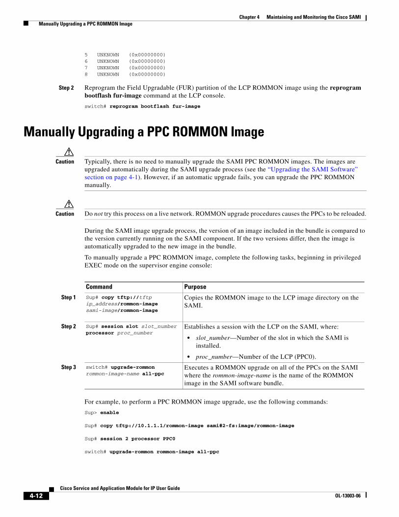
Caution Typically, there is no need to manually upgrade the SAMI PPC ROMMON images. The images are upgraded automatically during the SAMI upgrade process (see the “Upgrading the SAMI Software” section on page 4-1). However, if an automatic upgrade fails, you can upgrade the PPC ROMMON manually.
Caution Do not try this process on a live network. ROMMON upgrade procedures causes the PPCs to be reloaded.
During the SAMI image upgrade process, the version of an image included in the bundle is compared to the version currently running on the SAMI component. If the two versions differ, then the image is automatically upgraded to the new image in the bundle.
To manually upgrade a PPC ROMMON image, complete the following tasks, beginning in privileged EXEC mode on the supervisor engine console:
For example, to perform a PPC ROMMON image upgrade, use the following commands:
Sup> enable
Sup# copy tftp://10.1.1.1/rommon-image sami#2-fs:image/rommon-image
Sup# session 2 processor PPC0
switch# upgrade-rommon rommon-image all-ppc
Command Purpose
Step 1 Sup# copy tftp://tftp ip_address/rommon-image sami-image/rommon-image
Copies the ROMMON image to the LCP image directory on the SAMI.
Step 2 Sup# session slot slot_number processor proc_number
Establishes a session with the LCP on the SAMI, where:
• slot_number—Number of the slot in which the SAMI is installed.
• proc_number—Number of the LCP (PPC0).
Step 3 switch# upgrade-rommon rommon-image-name all-ppc
Executes a ROMMON upgrade on all of the PPCs on the SAMI where the rommon-image-name is the name of the ROMMON image in the SAMI software bundle.
4-12Cisco Service and Application Module for IP User Guide
OL-13003-06

Chapter 4 Maintaining and Monitoring the Cisco SAMI Reallocating SAMI PPC IO Memory
Reallocating SAMI PPC IO Memory
Note Reallocating SAMI PPC IO Memory is supported on SAMI Cisco IOS PPCs only.
Each of the PPCs on a SAMI has 2GB or 4GB DRAM. In PPCs with 2GB DRAM, 64 MB is allocated for IO memory by default. For SAMIs with 4GB DRAM, the default iomem size is specific to application. However, you can use the memory-size iomem command to reallocate the IO memory from the total available DRAM space. The no form of the iomem command returns to the default memory allocation.
Note Each application has different IO memory requirements. Please consult the application configuration and user guides for recommendations on IO memory and minimum DRAM required.
Caution It is not recommended that you change the IO memory allocation without careful consideration of the network requirements.
To reallocate memory on each of the PPCs (processors 3 through 8), use the memory-size iomem command to reallocate memory on each of the PPCs (processors 3 through 8). The memory-size iomem command cannot be used to configure the memory allocation on the LCP (processor 0).
After the I/O memory is configured using the memory-size iomen command, the remaining DRAM memory is used for processor memory.
After you configure the memory allocation, the configuration must be saved and the PPC reloaded for the configuration to take effect.
To reallocate the IO memory on a PPC, use the following commands:
Command Purpose
Step 1 Sup> enable Enters privileged EXEC mode.
Step 2 Sup# session slot slot_num processor proc_number
Establishes a session with a PPC on the SAMI, where:
• slot_number—Number of the slot in which the SAMI is installed.
• proc_number—Number of the PPC on the SAMI. Valid values are 3 through 8.
One session per processor can be established. To end a session, enter exit.
Step 3 Router> enable Enters privilege EXEC mode.
Step 4 Router# configure Enters global configuration mode.
Step 5 Router(config)# memory-size iomem 64 Allocates 64 MB of the DRAM memory to I/O memory and the remaining to processor memory.
Step 6 Router(config)# exit Exits global configuration mode.
4-13Cisco Service and Application Module for IP User Guide
OL-13003-06

Chapter 4 Maintaining and Monitoring the Cisco SAMI Recovering the SAMI
Recovering the SAMIThis section includes the following recovery procedures:
• Recovering from a PPC Lockout, page 4-14
• Recovering—Session Loss, page 4-17
• Recovering—LCP ROMMON or an Unstable LCP Image, page 4-17
Recovering from a PPC LockoutOccasionally, you might be unable to log into a SAMI PPC, either because of a configuration mistake, or because you have forgotten the password.
You can recover from this condition using the Break key during the boot process. This is the standard password recovery method supplied by the Cisco software running on the PPC. Additionally, because the SAMI PPC configuration files are stored on the supervisor, password recovery is also possible by modifying the configuration file of a PPC on supervisor.
Step 7 Router# write memory Saves the changes to the running configuration to the startup configuration file.
Step 8 Router# reload Reloads the PPC or the entire SAMI.
Depending on the requirements of the Cisco software application running on the SAMI PPCs, the reload command might reload the single PPC or the entire module. For example, when issued from the PPC running a distributed application such as the Cisco Content Services Gateway - 2nd Generation (CSG2), the reload command reloads the entire module.
Command Purpose
4-14Cisco Service and Application Module for IP User Guide
OL-13003-06

Chapter 4 Maintaining and Monitoring the Cisco SAMI Recovering the SAMI
Using Break to Recover from PPC Lockout
To recover from a lockout by sending the Break key, complete the following steps:
The following example illustrates using a break to recover from a PPC lockout:
Router# System Bootstrap, Version 12.3(20070512:064259) [BLD-bouncer.nightly 101], DEVELOPMENT SOFTWARECopyright (c) 1994-2007 by cisco Systems, Inc.BOUNCER platform with 1048576 Kbytes of main memoryImage:c7svcsami-ipbase-mz.bouncer.070724.p1p3Self decompressing the image : ########################################################## [OK] telnet> send break Restricted Rights Legend Use, duplication, or disclosure by the Government issubject to restrictions as set forth in subparagraph(c) of the Commercial Computer Software - RestrictedRights clause at FAR sec. 52.227-19 and subparagraph(c) (1) (ii) of the Rights in Technical Data and ComputerSoftware clause at DFARS sec. 252.227-7013. cisco Systems, Inc. 170 West Tasman Drive San Jose, California 95134-1706 Cisco IOS Software, SAMI Software (SAMI-M), Version 12.4(nightly.2070512) NIGHTLY BUILD, synced to bouncer BOUNCER_NIGHTLY_061020Copyright (c) 1986-2007 by Cisco Systems, Inc.Compiled Sat 12-May-07 03:03 by userAImage text-base: 0x400120D4, data-base: 0x40FCB5E0 hw_version is 3, 256 sectors, 32M flash used.
Command Purpose
Step 1 telnet> send break Connects to the console and sends the Break key as the supervisor engine boots from ROMMON to Cisco application software.
Note Break is enabled for 60 seconds after boot up is initiated.
The ROMMON breaks out of the booting process and provides the ROMMON prompt.
Step 2 rommon# confreg Sets the config-register and forces the supervisor engine to produce a configuration dialog. This method assures that you do not see the existing configurations or passwords without knowing the password.
After the supervisor is up, use cut and paste or the tftp command to copy the configurations to the supervisor engine and then to NVRAM.
Step 3 rommon# reset Resets (or power cycles) to enable the new configuration to take effect.
4-15Cisco Service and Application Module for IP User Guide
OL-13003-06

Chapter 4 Maintaining and Monitoring the Cisco SAMI Recovering the SAMI
Initializing flashfs... *** System received an abort due to Break Key ***signal= 0x3, code= 0x500, context= 0x434b62f8PC = 0x40cf5878, Vector = 0x500, SP = 0x43199ad4rommon 1 > confreg 0x2142
You must reset or power cycle for new config to take effectrommon 2 > reset
Modifying the Configuration File to Recover from a PPC Lockout
To recover from a PPC lockout by modifying the configuration file stored on the supervisor engine, complete the following steps:
The following example illustrates modifying a configuration file to recover from a PPC lockout:
Sup# dir bootflash:SLOT1SAMIC3.cfgDirectory of bootflash:/SLOT1SAMIC3.cfg 151 -rw- 265291 May 13 2007 22:48:31 +00:00 SLOT1SAMIC3.cfg 65536000 bytes total (11841704 bytes free)
Sup# copy bootflash:/SLOT1SAMIC3.cfg tftp://1o.10.0.254/auto/tftp-blr-users3/username/configs/SLOT1SAMIC3.cfgAddress or name of remote host [9.10.0.254]? Destination filename [auto/tftp-blx-users3/username/configs/SLOT1SAMIC3.cfg]? !!!265291 bytes copied in 0.416 secs (637719 bytes/sec)
Sup# copy tftp://10.10.0.254/tftpboot/username/configs/SLOT1SAMIC3.cfg bootflash:SLOT1SAMIC3.cfg
Destination filename [SLOT1SAMIC3.cfg]? %Warning:There is a file already existing with this name Do you want to over write? [confirm]
Accessing tftp://10.10.0.254/auto/tftp-blx-users3/username/configs/SLOT1SAMIC3.cfg...Loading auto/tftp-blx-users3/username/configs/SLOT1SAMIC3.cfg from 9.10.0.254 (via Vlan10): !![OK - 265271 bytes]265271 bytes copied in 1.308 secs (202807 bytes/sec)Sup#
Command Purpose
Step 1 Sup# dir bootflash:filename.cfg Copies the configuration file from supervisor engine to a UNIX machine to edit it.
Step 2 Sup# copy tftp:dir tftpboot/username/configs/filename.cfg bootflash:filename.cfg
Copies the configuration file back to the supervisor engine after editing it.
Step 3 Sup# hw-module module mod_num reset Reloads the entire SAMI.
4-16Cisco Service and Application Module for IP User Guide
OL-13003-06

Chapter 4 Maintaining and Monitoring the Cisco SAMI Recovering the SAMI
sup# dir bootflash:SLOT1SAMIC3.cfg Directory of bootflash:/SLOT1SAMIC3.cfg 152 -rw- 265271 May 14 2007 02:41:03 +00:00 SLOT1SAMIC3.cfg 65536000 bytes total (11576304 bytes free)Sup#Sup# hw-module module 1 reset Sup#
Recovering—Session LossIf the session between the supervisor engine and a SAMI PPC fails, you can use the following steps to try to recover the session and collect information that can be useful in determining the cause of the session loss.
When a session is lost, the following error message displays:
sami: No response from IOS processor x, resetting processor
To try to recover a PPC session and collect troubleshooting information, use the following command in privileged EXEC mode from the supervisor engine console:
The following example illustrates powering down and resetting a SAMI in slot 5 of the router chassis:
Sup> enableSup# hw-module module 5 resetSup#
Recovering—LCP ROMMON or an Unstable LCP ImageIf the SAMI LCP (processor 0) is in ROMMON, the upgrade command from the supervisor is failing, or when there is not a usable image on the SAMI, you can use the following procedure to recover the SAMI.
If the output from the show module command issued from the supervisor indicates the SAMI status is “other,” and the module is not coming out of this state, first verify that the LCP is in ROMMON by issuing the following commands from the supervisor:
Command Purpose
Sup# hw-module module mod-num reset Resets the SAMI by powering it down and up.
Command Purpose
Step 1 Sup# remote login switch Accesses the switch processor.
Step 2 Sup-sp# svclc console sami_slot_num Establishes a session with the LCP console if the LCP is in ROM-monitor state.
4-17Cisco Service and Application Module for IP User Guide
OL-13003-06

Chapter 4 Maintaining and Monitoring the Cisco SAMI Recovering the SAMI
The following example illustrates accessing the switch processor:
Sup> remote login switchprocessorTrying switch...Entering CONSOLE for SwitchType "^C^C^C" to end this session
The following example illustrates establishing a session with an LCP console that is not in ROMMON. If the LCP is not in ROMMON, the LCP should be functioning properly and you can use the session slot command to access the LCP console.
Sup-sp# svclc console 3processor 0 consoleCard in slot 3 is not in ROMMON.
The following example illustrates establishing a session with an LCP console that is in ROMMON. If the LCP is in ROMMON, proceed to loading a SAMI using an image on the supervisor:
Sup-sp# svclc console 3Entering svclc ROMMON of slot 3 ...Type “end” to end the session.processor 0 is in ROMMON.
rommon 2> endprocessor 0 ROMMON tunneling sessionEnd of tunneling command.
Sup-sp#exitSupervisor RP processorSup#
If an image uploaded to the LCP is failing, the following procedure can be used to recover the LCP by rebooting it from a stable image on the supervisor.
If an image uploaded to the SAMI using upgrade command is failing, or if the SAMI does not have a valid usable image, or to reboot a SAMI whose LCP in ROMMON, complete the following steps to reboot using a stable image loaded directly from supervisor engine.
To reboot an LCP using a stable image on the supervisor engine, complete the following steps:
Command Purpose
Step 1 Sup# boot device module slot_num disk0:image_name
Sets the boot variable for the SAMI LCP.
Step 2 Sup# hw-module module slot_num boot eobc Boots using the image downloaded through EOBC.
Step 3 Sup# hw-module module slot_num reset Resets the module by turning the power off and then on.
Step 4 Sup# upgrade hw-module slot sami_slot_num software disk0:image_name
Copies the bundle from the specified URL to the compact flash on the SAMI in the specified slot and sets the initialization parameters.
Note This command is required to ensure that future reboots of the SAMI will automatically come up with the specified image.
4-18Cisco Service and Application Module for IP User Guide
OL-13003-06

Chapter 4 Maintaining and Monitoring the Cisco SAMI Recovering the SAMI
The following example illustrates rebooting a SAMI in slot 3 using an image on the supervisor:
Sup> boot device module 3 disk0:c7svcsami-ipbase-mz.bouncer.070724.p1p3Sup# hw-module module 3 boot eobcSup# hw-module module 3 reset:Sup# upgrade hw-module slot sami_slot_num software disk0:image_name
To display the software image on the LCP, use the show version command in EXEC mode.
switch# show version
Recovering—No Usable Image on the SAMI CF:If the SAMI LCP (PPC 0) is in ROMMON, the upgrade command from the supervisor is failing, or when there is not a usable image on the SAMI, the following procedure can be used to recover the SAMI.
1. If the output from the show module command issued from the supervisor indicates the SAMI status is “other,” and the module is not coming out of this state, first verify that the LCP is in ROMMON by issuing the following commands from the supervisor:
Sup# remote login switchprocessorTrying switch...Entering CONSOLE for SwitchType "^C^C^C" to end this session
The following example illustrates establishing a session with an LCP console that is not in ROMMON. If the LCP is not in ROMMON, the LCP should be functioning properly and you can use the session slot command to access the LCP console.
Sup-sp# svclc console 3processor 0 consoleCard in slot 3 is not in ROMMON.
The following example illustrates establishing a session with an LCP console that is in ROMMON. If the LCP is in ROMMON, proceed to loading a SAMI using an image on the supervisor:
Sup-sp# svclc console 3Entering svclc ROMMON of slot 3 ...Type “end” to end the session.processor 0 is in ROMMON.
rommon 1> endprocessor 0 ROMMON tunneling sessionEnd of tunneling command.
Sup-sp#exitSupervisor RP processorSup#
2. To reboot an LCP using a stable image on the supervisor engine, complete the following steps:
The following example illustrates rebooting a SAMI in slot 3 using an image on the supervisor:
Sup(config)# boot device module 3disk0:c7svcsami-ipbase-mz.bouncer.070724.p1p3Sup# hw-module module 3 boot eobcSup# hw-module module 3 reset:Sup# upgrade hw-module slot 3 software disk0:image_name
4-19Cisco Service and Application Module for IP User Guide
OL-13003-06

Chapter 4 Maintaining and Monitoring the Cisco SAMI Configuring, Exporting, and Importing RSA Keys on a SAMI PPC
Configuring, Exporting, and Importing RSA Keys on a SAMI PPC
Note The Configuring, Exporting, and Importing RSA Keys feature is supported only on the SAMI Cisco IOS PPCs.
The Configuration File Storage on Supervisor feature only stores the PPC startup configuration files. Crypto configurations, such as the RSA key generation for Secure Shell (SSH) is stored locally on nvram:private-config. Therefore, if a SAMI card that contains crypto configuration needs to be replaced, the crypto configuration must reapplied by either by manually reconfiguring it on the new card, or by exporting the crypto configuration to the supervisor and then importing the configuration onto the new card.
For information about the Configuration File Storage on Supervisor feature, see the “Enabling the Supervisor to Store PPC Startup Configuration Files” section on page 3-6.
The following steps configure, export, and import RSA keys on a SAMI PPC (PPC3):
Step 1 Complete the required configuration for SSH on the PPC.
Router(config)#hostname PPC3PPC3(config)#interface gigabitEthernet 0/0.11PPC3(config-if)#encapsulation dot1Q 11
Note If the interface doesn't support baby giant frames maximum MTU of the interface has to be reduced by 4 bytes on both sides of the connection to properly transmit or receive large packets. Please refer to Cisco IOS documentation on configuring IEEE 802.1Q VLANs.
PPC3(config-if)#ip address 1.1.1.13 255.255.255.0PPC3(config-if)#no shutPPC3(config-if)#exit PPC3(config)#ip sshPPC3(config)#ip ssh version 2
Please create RSA keys (of atleast 768 bits size) to enable SSH v2.
PPC3(config)#crypto key generate rsa exportable label sshkeys ? encryption Generate a general purpose RSA key pair for signing and encryption general-keys Generate a general purpose RSA key pair for signing and encryption modulus Provide number of modulus bits on the command line signature Generate a general purpose RSA key pair for signing and encryption storage Store key on specified device usage-keys Generate separate RSA key pairs for signing and encryption <cr>
PPC3(config)#crypto key generate rsa exportable label sshkeys modulus 1024The name for the keys will be: sshkeys
% The key modulus size is 1024 bits% Generating 1024 bit RSA keys, keys will be exportable...[OK]
PPC3(config)#SAMI 1/3: *Mar 1 00:02:43.419: %SSH-5-ENABLED: SSH 2.99 has been enabledPPC3(config)#
4-20Cisco Service and Application Module for IP User Guide
OL-13003-06

Chapter 4 Maintaining and Monitoring the Cisco SAMI Configuring, Exporting, and Importing RSA Keys on a SAMI PPC
PPC3(config)#username username password 0 passwordPPC3(config)#enable password 0 labPPC3(config)#aaa new-modelPPC3(config)#end
Step 2 Verify that SSH is enabled.
PPC3#show crypto key mypubkey rsa% Key pair was generated at: 00:02:43 UTC Mar 1 2002Key name: sshkeys Storage Device: private-config Usage: General Purpose Key Key is exportable. Key Data: 30819F30 0D06092A 864886F7 0D010101 05000381 8D003081 89028181 00A4B01C 6494169A 94419B29 5E99C04E FB7DD3D3 534F5FD5 E26CAB01 DF7F2582 C8763CAE 7DE3D94A 770CAE9A A1B73F1D 16CF283C 6C68C023 78B1DC3A BB7021A7 75ECD3A8 AE2F9591 1AF03D63 DE31A35C 8B41EB4C EAD3C1C9 528FD804 DF5032A6 A9EE53FF 87816716 9CC746D9 79597478 842BED0D CDE8F77A E1E0D535 ABD478B9 E5020301 0001% Key pair was generated at: 00:00:03 UTC Mar 1 2002Key name: sshkeys.serverTemporary key Usage: Encryption Key Key is not exportable. Key Data: 307C300D 06092A86 4886F70D 01010105 00036B00 30680261 00C96B2B 768F0C3B 6810BFE7 9211CB43 7671E7A1 BC51C393 076FEF75 1ADE8114 03293B1A F2A1ECD0 F31AFC90 791342C0 3E9F3C1D AB5058B1 8B08698F AAF79D43 7469DDEB A1A1D3E8 33708E1B 0AA5F8D8 54364C8A E184A61C 203C2265 2C6FFA66 C3020301 0001PPC3#PPC3#show ip sshSSH Enabled - version 2.99Authentication timeout: 120 secs; Authentication retries: 3
Step 3 Save the configuration using the write memory command so that the startup configuration is stored on the supervisor, and the crypto configuration is stored on NVRAM.
PPC3#dir nvram:Directory of nvram:/
126 -rw- 580 <no date> startup-config 127 ---- 5 <no date> private-config 1 -rw- 0 <no date> ifIndex-table 2 ---- 4 <no date> rf_cold_starts
131072 bytes total (128387 bytes free)
% Unknown command or computer name, or unable to find computer addressPPC3#
PPC3#write memoryWriting bootflash:SLOT1SAMIC3.cfg !Writing slavebootflash:SLOT1SAMIC3.cfg %rcp: slavebootflash:SLOT1SAMIC3.cfg: No such file or directory
%Error opening rcp://*****@127.0.0.61/slavebootflash:SLOT1SAMIC3.cfg (Undefined error)Building configuration...[OK]
PPC3#SAMI 1/3: *Mar 1 00:08:46.151: %C6K_SAMI_CENTRALIZED_CONFIG-6-UPLD_SUCCESS: Success: config uploaded to supervisor bootflash:SAMI 1/3: *Mar 1 00:08:46.175: %C6K_SAMI_CENTRALIZED_CONFIG-4-UPLD_FAILURE_STDBY: Failed to upload config to rcp://[email protected]/slavebootflash:SLOT1SAMIC3.cfg.
4-21Cisco Service and Application Module for IP User Guide
OL-13003-06

Chapter 4 Maintaining and Monitoring the Cisco SAMI Configuring, Exporting, and Importing RSA Keys on a SAMI PPC
slavebootflash: is hosted on the standby supervisor engine. Failure to write to slavebootflash: or slavebootdisk: may be safely ignored when there is no standby supervisor engine. Otherwise, this should be considered as an error, check for space on standby supervisor engine, squeeze standby supervisor engine's slavebootflash: if needed.SAMI 1/3: *Mar 1 00:08:46.175: %C6K_SAMI_CENTRALIZED_CONFIG-6-UPLOAD_SUCCEEDED: config uploaded to 1 supervisor file system(s)
PPC3#
PPC3#dir nvram:Directory of nvram:/
126 -rw- 580 <no date> startup-config 127 ---- 1906 <no date> private-config 1 -rw- 0 <no date> ifIndex-table 2 ---- 4 <no date> rf_cold_starts
131072 bytes total (126486 bytes free)PPC3#
Step 4 Export the RSA keys to the supervisor using RCP:
PPC3(config)# crypto key export rsa sshkeys pem url rcp://[email protected]/bootflash:SLOT1SAMIC3PRIV.cfg 3des myrsakeys% Key name: sshkeys Usage: General Purpose KeyExporting public key...Address or name of remote host [127.0.0.61]? Destination username [sami]? Destination filename [bootflash:SLOT1SAMIC3PRIV.cfg.pub]? % File 'bootflash:SLOT1SAMIC3PRIV.cfg.pub' already exists.% Do you really want to overwrite it? [yes/no]: yesWriting bootflash:SLOT1SAMIC3PRIV.cfg.pub Writing file to rcp://[email protected]/bootflash:SLOT1SAMIC3PRIV.cfg.pub!Exporting private key...Address or name of remote host [127.0.0.61]? Destination username [sami]? Destination filename [bootflash:SLOT1SAMIC3PRIV.cfg.prv]? % File 'bootflash:SLOT1SAMIC3PRIV.cfg.prv' already exists.% Do you really want to overwrite it? [yes/no]: yesWriting bootflash:SLOT1SAMIC3PRIV.cfg.prv Writing file to rcp://[email protected]/bootflash:SLOT1SAMIC3PRIV.cfg.prv!
PPC3(config)#
Step 5 Replace the SAMI as necessary. Verify that the startup-config is restored and no crypto configurations are present:
PPC3#show crypto key mypubkey rsa
PPC3#
Step 6 Import the keys stored on supervisor:
PPC3(config)# crypto key import rsa sshkeys exportable url rcp://[email protected]/bootflash:SLOT1SAMIC3PRIV.cfg myrsakeys
% Importing public General Purpose key or certificate PEM file...Address or name of remote host [127.0.0.61]? Source username [sami]? Source filename [bootflash:SLOT1SAMIC3PRIV.cfg.pub]? Reading file from rcp://[email protected]/bootflash:SLOT1SAMIC3PRIV.cfg.pub!% Importing private General Purpose key PEM file...Address or name of remote host [127.0.0.61]?
4-22Cisco Service and Application Module for IP User Guide
OL-13003-06

Chapter 4 Maintaining and Monitoring the Cisco SAMI Establishing a Console Connection on the SAMI
Source username [sami]? Source filename [bootflash:SLOT1SAMIC3PRIV.cfg.prv]? Reading file from rcp://[email protected]/bootflash:SLOT1SAMIC3PRIV.cfg.prv!% Key pair import succeeded.
PPC3(config)#SAMI 1/3: *Mar 1 00:06:42.323: %SSH-5-ENABLED: SSH 2.99 has been enabledPPC3(config)#
Step 7 Verify that the crypto configurations have imported successfully:
PPC3#show crypto key mypubkey rsa % Key pair was generated at: 00:06:42 UTC Mar 1 2002Key name: sshkeys Storage Device: not specified Usage: General Purpose Key Key is exportable. Key Data: 30819F30 0D06092A 864886F7 0D010101 05000381 8D003081 89028181 00A4B01C 6494169A 94419B29 5E99C04E FB7DD3D3 534F5FD5 E26CAB01 DF7F2582 C8763CAE 7DE3D94A 770CAE9A A1B73F1D 16CF283C 6C68C023 78B1DC3A BB7021A7 75ECD3A8 AE2F9591 1AF03D63 DE31A35C 8B41EB4C EAD3C1C9 528FD804 DF5032A6 A9EE53FF 87816716 9CC746D9 79597478 842BED0D CDE8F77A E1E0D535 ABD478B9 E5020301 0001% Key pair was generated at: 00:06:42 UTC Mar 1 2002Key name: sshkeys.serverTemporary key Usage: Encryption Key Key is not exportable. Key Data: 307C300D 06092A86 4886F70D 01010105 00036B00 30680261 009D6B6B AF9B407C A4C8CBAC 6F2E5BBF E724229B 17B607F8 069AA2C7 67DEB599 DD47D2C8 E6F29884 662ABF9D B871E087 9808E1CB BA361F44 439940BC 3D6129BA B6F0EB30 7747DF42 22DB2A11 DF26632E 54B36C0F 8205EF14 80B1ED6C BC3FFF81 81020301 0001
PPC3#show ip sshSSH Enabled - version 2.99Authentication timeout: 120 secs; Authentication retries: 3PPC3#
Step 8 Verify SSH:
7600#ssh -v 2 -l <username> 1.1.1.13
Password:
PPC3>enablePassword: PPC3#
Establishing a Console Connection on the SAMI You can establish a direct serial connection between your terminal and the SAMI LCP by making a serial connection to the console port on the front of the SAMI. The console port is an asynchronous RS-232 serial port with an RJ-45 connector. Any device connected to this port must be capable of asynchronous transmission. Connection requires a terminal configured as 9600 baud, 8 data bits, 1 stop bit, no parity.
After connected, use any terminal communications application to establish a session with a SAMI PPC. A connection to a SAMI PPC requires that the PPC be configured to be accessible from the console port using the console-select db1 or console-select db2 command. For information on the console-select commands, see the “SAMI LCP Commands” section on page E-1.
4-23Cisco Service and Application Module for IP User Guide
OL-13003-06

Chapter 4 Maintaining and Monitoring the Cisco SAMI Configuring Health Monitoring
The following procedure uses HyperTerminal for Windows to establish a session with the SAMI:
1. Launch HyperTerminal. The Connection Description window appears.
2. In the Name field, enter a name for your session.
3. Click OK. The Connect To window appears.
4. From the drop-down list, choose the COM port to which the device is connected.
5. Click OK. The Port Properties window appears.
6. Set the port properties:
– Baud Rate = 9600
– Data Bits = 8
– Flow Control = none
– Parity = none
– Stop Bits = 1
7. To connect, click OK.
8. To access the CLI prompt, press Enter.
switch login:
After a session is established, choose Save As from the File menu to save the connection description. Saving the connection description has the following two advantages:
• The next time you launch HyperTerminal, the session is listed as an option under Start > Programs > Accessories > HyperTerminal > Name_of_session. This option lets you reach the CLI prompt directly without going through the configuration steps.
• You can connect your cable to a different device without configuring a new HyperTerminal session. If you use this option, make sure that you connect to the same port on the new device as was configured in the saved HyperTerminal session. Otherwise, a blank window appears without a prompt.
Configuring Health MonitoringThe following sections discuss the two types of health monitoring on the Cisco SAMI:
• PPC Health Monitoring, page 4-24
• LCP Health Monitoring, page 4-27
PPC Health Monitoring
Note By default, health monitoring is enabled on SAMI COSLI PPCs. Therefore, to use the Health Monitoring feature, no configuration tasks are required on the SAMI COSLI PPC.
PPC health monitoring is configured on the SAMI PPCs. When configured, the PPC monitors the health of a path by sending probes to a destination and waiting for a response. If the PPC does not receive a response to a probe that it has sent, it determines that the path is not healthy and sends a notification to the SAMI LCP, which then initiates a module reload.
4-24Cisco Service and Application Module for IP User Guide
OL-13003-06

Chapter 4 Maintaining and Monitoring the Cisco SAMI Configuring Health Monitoring
The PPC uses the following two categories to identify the health of a path:
• Passed—The PPC receives a valid response to a probe that it has sent.
• Failed—The PPC does not receive a valid response to a probe or is unable to reach a destination for a specified number of retries.
To enable health monitoring on the Cisco IOS PPC, complete the following steps:
To display health monitoring status and counters on a Cisco IOS PPC, use the following command in privilege EXEC mode:
Command Purpose
Step 1 Sup# session slot slot_number processor proc_number
Establishes a session to a PPC on the SAMI, where:
• slot_number—Number of the slot in which the SAMI is installed.
• proc_number—Number of the PPC on the SAMI. Valid values are 3 through 8.
One session per processor can be established.
Step 2 Router> enable Enters privilege EXEC mode.
Step 1 Router# sami health-monitoring {ixp1 | ixp2}
Enables health monitoring on the paths between the PPC and IXP1 and IXP2 (future).
By default, health monitoring is enabled for IXP1 and disabled for IXP2.
Step 2 Router# sami health-monitoring probe ip-address [interval seconds] [retries number]
Enables health monitoring on all of the paths between the PPC and the supervisor, where:
• ip-address—Destination IP address on the supervisor. The IP address must be in the global vrf table and a suitable local ip address will be used to reach the remote probe address on supervisor
• interval seconds—Interval, in seconds, between probes. A valid value is a number between 1 and 600.
• retries number—Number of times a probe can be resent before it is marked as failed. A valid value is a number between 10 and 100.
Step 3 Router# sami health-monitoring {ixp1 | ixp2 | probe} reset
Configures the module to be reset when a path has failed, where:
• ixp1—Resets the module if a check to IXP1 fails.
• ixp2—Resets the module if a check to IXP2 fails (future).
• probe—Resets the module if a check to the supervisor fails.
Command Purpose
Step 1 Router# show sami health-monitoring
Displays health monitoring status and counters for the path to IXP1, IXP2 (future), and the supervisor.
4-25Cisco Service and Application Module for IP User Guide
OL-13003-06

Chapter 4 Maintaining and Monitoring the Cisco SAMI Configuring Health Monitoring
For example:
• To enable a Cisco IOS PPC, hostname “PPC4” to monitor the health of the path to IXP1, monitor the health of the path to the supervisor, and to reset the module if the sanity check to the supervisor module fails, enter the following commands:
PPC4# sami health-monitoring ixp1PPC4# sami health-monitoring probe ip-address [interval seconds] [retries number]PPC4# sami health-monitoring probe reset
• To show health monitoring-related counters and status, enter the following command:
PPC4#show sami health-monitoringIXP1: DISABLED0/0 Missed/Rcvd consecutive responses0/0 Missed/Rcvd cumulative responses0 Failed to sendIXP2: DISABLED0/0 Missed/Rcvd consecutive responses0/0 Missed/Rcvd cumulative responses0 Failed to sendICMP PROBE: PROBING0/0 Missed/Rcvd consecutive responses10/8 Missed/Rcvd cumulative responses40 Failed to send
When you view the show sami health-monitoring command output, note that:
– IXP1, IXP2, ICMP PROBE status can be one of the following:
- PROBING—Health monitoring is enabled, no responses received or failed to send a message on previous resend expiration.
- ACTIVE—Response to probe received from peer.
- FAILED—No response received. Communication failed with peer.
- DISABLED—Health monitoring is disabled.
– Missed consecutive responses—Indicates the consecutive number of responses missed. This counter starts at 0 and is incremented each time a response is missed until timeout expiry. This counter is reset each time a response is received or if the PPC fails to send a message.
– Rcvd consecutive responses—Indicates the consecutive number of messages sent. This counter starts at 0 and is incremented each time a valid response is received. It is reset each time a response is missed until timeout expiry or if the PPC fails to send a message.
– Missed/Rcvd cumulative responses—Free running counter of total responses missed or received until timeout expiry.
– Failed to send counter—Incremented each time a message cannot be sent upon resend timer expiration and if the health monitoring is administratively enabled. This can happen due to no IO memory, no suitable local IP address, and so on.
4-26Cisco Service and Application Module for IP User Guide
OL-13003-06

Chapter 4 Maintaining and Monitoring the Cisco SAMI Monitoring the SAMI
LCP Health MonitoringLCP health monitoring is not configurable. It is a default function performed on the LCP.
When a PPC fails, LCP health monitoring either reloads the PPC or the entire SAMI depending on the application running on the SAMI PPCs. For example, if the Cisco Content Services Gateway - 2nd Generation (CSG2) application is running on the SAMI PPCs, the LCP reloads the entire module if a PPC fails. If a mobile wireless gateway such as the Cisco Gateway GPRS Support Node (GGSN) is running on the SAMI PPCs, the LCP reloads only the PPC that is failing.
Additionally, when a PPC has not booted for a specific amount of time (the default is 15 minutes), LCP health monitoring reloads that PPC (or the entire module if running the Cisco CSG2 application). If a PPC never comes up, the LCP notes that the PPC does not come up, and upon the next reload of the LCP, if another PPC never comes up, the LCP increments a safe counter. When the safe counter reaches 3, the LCP will not start the PPCs and enters safe mode. When the SAMI enters safe mode, a message displays that indicates the SAMI is running in safe mode. When in safe mode, you can perform debugging.
When the LCP enters safe mode, it resets the safe counter to zero so that on next reboot, the SAMI PPCs will boot as normal.
Monitoring the SAMIUse the following list of show commands to monitor the SAMI.
For a description of these commands, their keywords and variables, see Appendix A, “Using the Command-Line Interfaces.”
Monitoring a SAMI from the Supervisor Console
The following privilege EXEC commands can be used to monitor SAMI activity from the supervisor engine console:
Command Description
clear sami module Clears SAMI traffic counters.
show inventory Displays the product inventory list of all Cisco products that are installed in a networking device.
show logging slot Displays logging status and counters for all processors on a SAMI using RCAL.
show logging summary Displays logging status and counters for all processors on all SAMIs in a chassis using RCAL.
show login timeout Displays the login session idle timeout value.
show module Displays module status and information.
show sami module Displays traffic counters for a SAMI.
show svclc module Displays all VLAN groups associated with a module.
show svclc vlan-group Displays the group configuration for the SAMI and the associated VLANs.
show upgrade software progress Displays information about the progress of software upgrades.
4-27Cisco Service and Application Module for IP User Guide
OL-13003-06

Chapter 4 Maintaining and Monitoring the Cisco SAMI Monitoring the SAMI
Monitoring the SAMI from the LCP Console
The following privilege EXEC commands can be used to monitor SAMI activity from the SAMI LCP console:
Monitoring SAMI from the Cisco IOS PPC Console
The following privilege EXEC commands can be used to monitor SAMI activity from a SAMI Cisco IOS PPC console:
Command Description
show cde health Displays the CDE health.
show cde stats {cumulative | delta} Displays either cumulative CDE counters or the delta counters from previous invocation of the show cde stats command.
show cde vlan vlan_id Provides VLAN mapping for the specified VLAN ID. This is either IXP0 or CP. CP indicates LCP.
show daughtercard registers Displays the field programmable gate array (FPGA) or complex programmable logic device (CPLD) registers for a daughter card on the SAMI.
show daughtercard statistics Displays the field programmable gate array (Kabob) statistics for one of the daughter cards on the SAMI.
show login timeout Displays the login session idle timeout value.
show running-config Displays the running configuration information.
show startup-config Displays information about the startup configuration.
show tech-support Displays information that is useful to technical support when reporting a problem.
show version Displays information about the currently loaded software version along with hardware and device information.
Command Description
show platform Displays platform information.
show sami health monitoring Displays health monitoring status and counters for the paths to the IXP1, IXP2 (future), and the supervisor.
show sami info Displays information about the startup configuration.
show sami ipcp ipc Display counters specific to IPCP interprocessor communication (IPC) for the IXP or PPCs.
show sami ipcp statistics Displays the counters for IPCP packet counters processed to and from IPCP peers.
4-28Cisco Service and Application Module for IP User Guide
OL-13003-06

Chapter 4 Maintaining and Monitoring the Cisco SAMI Monitoring the SAMI
Monitoring SAMI from the COSLI PPC Console
The following privilege EXEC commands can be used to monitor SAMI activity from a SAMI COSLI PPC console:
Command Description
show arp Displays the current active IP address-to-MAC address mapping in the Address Resolution Protocol (ARP) table, statistics, or inspection or timeout configuration.
show buffer Displays the contents of the trace buffer.
show bufferlist Displays the names of all trace buffers.
show clock Displays the current date and time settings of the system clock.
show copyright Displays the software copyright information for the PPC.
show crashinfo Displays the contents of the crash file stored in Flash memory.
show debug Displays debug flags.
show eventlog Displays the event log.
show gfastats Displays the current gianfar Ethernet driver traffic counters.
show hosts Displays the hosts on a PPC.
show icmp statistics Displays the Internet Control Message Protocol (ICMP) statistics.
show interface Displays interface information.
show ip interface brief Displays a brief configuration and status summary of all interfaces or a specified VLAN.
show ip interface vlan Displays a configuration and status summary of a specified VLAN.
show ixpstats Displays the contents of the IXP stastistics file.
show logging Displays the current syslog configuration and syslog messages.
show processes Displays general information about all of the processes running on the PPC.
show running-config Displays the running configuration of a PPC.
show snmp Displays the Simple Network Management Protocol (SNMP) statistics and configured SNMP information.
show startup-config Displays the startup configuration of a PPC.
show system Displays the system information of a PPC.
show tcp statistics Displays Transmission Control Protocol (TCP) statistics.
show tech-support Displays information that is useful to technical support when reporting a problem with your PPC.
show telnet Displays information about the Telnet session
show terminal Displays the console terminal settings.
4-29Cisco Service and Application Module for IP User Guide
OL-13003-06

Chapter 4 Maintaining and Monitoring the Cisco SAMI Monitoring the SAMI
show udp statistics Display UDP statistics.
show version Displays the version information of system software that is loaded in flash memory and currently running on the PPC.
show vlans Displays the VLANs on the PPC downloaded from the supervisor engine.
Command Description
4-30Cisco Service and Application Module for IP User Guide
OL-13003-06