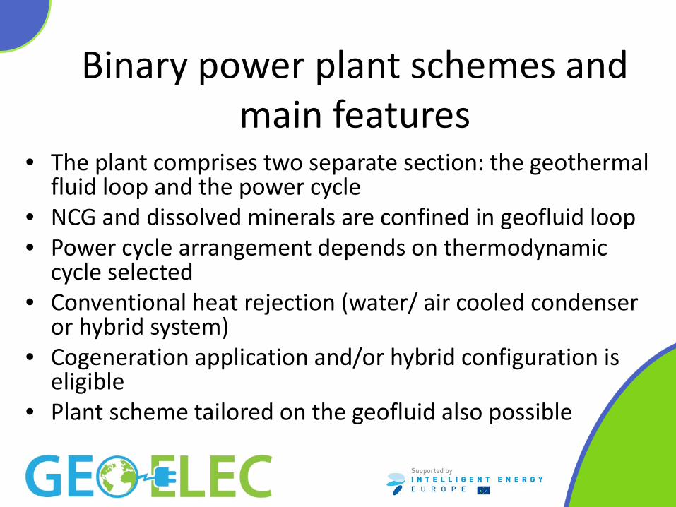
Main features and issues - Geoelec technology Main features: • Power generation by means of closed thermodynamic cycle • Geothermal fluid loop and power cycle are completely separated
41
Binary geothermal power plants Main features and issues Paola Bombarda Gecos Group, Dipartimento di Energia Politecnico di Milano Pisa, October 9 th , 2013
• Geothermal fluid loop • Thermodynamic cycles • Plant power balance • Case study: Soultz plant • High enthalpy and hybrid plant schemes • Main components • Operation and maintenance
Binary technology
Main features: • Power generation by means of closed thermodynamic
cycle • Geothermal fluid loop and power cycle are completely
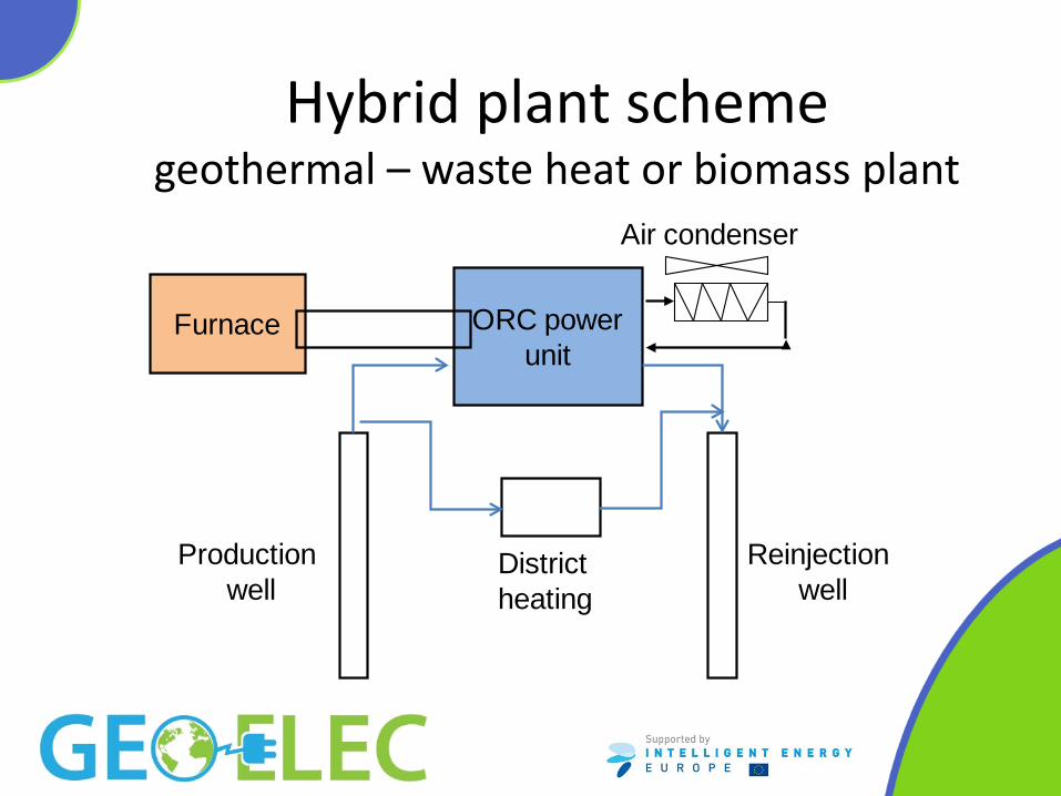
separated • Nearly zero emission plant (for all-liquid geofluid) • Suitable for integration with other energy sources (solar, biomass, waste....)
The geothermal fluid loop
Power plant
Relatore
Note di presentazione
NB tutto liq; portata ufficialmente costante; REM geofluid properties may change continoulsly thoughout the plant according p,T NB T at reinjection. Scaling problem
Geothermal fluid gathering
• Doublet: (1 production well, 1 injection well) is the typical layout
• Triplet is also used
• Multi-well, with several modules is being discussed
Relatore
Note di presentazione
The scheme may be modified during exploitation because of sustainable exploitation SUSTAINABLE GDH RESERVOIR MANAGEMENT (pres Strasburg 2012 Ungemach-Antics) SUSTAINABILITY MINING SCHEMES Sustaining 75 yrs System life INITIAL DOUBLET0-25 yrs NEW DOUBLET51-75 yrs INTERMEDIATE TRIPLET ARRAY26-50 yrs A) Initial cased wells 9”5/8 casings B) Former doublet wells lined (7”) as injector wells New anti-corrosion production well C) Former injector wells abandoned New anti-corrosion injection well
The downhole pump: lineshaft (LSP), submersible (ESP), hydraulically driven (HTP)
Main issues: depth, pumping head, temperature, reliability and availability
Source: TP-Geoelec) “Strategic Research Priorities for Geothermal Electricity»
Relatore
Note di presentazione
Rem tesi Sandrini sempre in funzione; Lineshaft low rpm 10-50 stages (prtichett) Submersible higher rpm lower stage number ump type Pros Cons LSP No electric parts in hole. Higher efficiency (surface motor). Long lifetime. Withstands high temperatures (up to 200°C). Attractive costs.Limited to vertical section. Requires 133/8“ casing OD. Delicate handling (installation/removal). Definition of enclosing tubing coating materials and bearing make up lubricating fluid. ESP High submersion depths. Long lifetime. High flow rates in limited casing ID's (250 m3/hr in 9"5/8). Withstands high temperatures (up to 180-200°C). Solution gas handling (in hole separator). Worldwide service facilities. Can accommodate deviated sections. Lower efficiency at Soultz (however, the technology has a lot of potential for efficiency increase). Electric insulation shortcomings. Higher costs. HTP Long lifetime. No electric parts in hole. Withstands very high temperatures (> 200°C). Low efficiency (additional energy conversion item). Limited to vertical section and large diameters (13” 3/8 OD) required. Packer anchoring problems. High costs. Limited manufacturing/service facilities. Challenges essentially concern geopower issues, heat to power, conversion cycles. The upper temperature limits of submersible pumps stand presently at 180°C-200°C. This clearly means that production from high enthalpy resources, the wide majority of which address formation temperatures above 200°C, is bound to vapour lift and related thermochemical (mainly scaling) and well plugging shortcomings, caused by in hole flashing of the geothermal brine. Status As of late 2009, most geopower wells operating in the 120-180°C temperature range, eligible to binary (Organic Rankine Cycle – ORC) conversion technology are serviced by downhole pump units of LSP and (to a lesser extent though) ESP types. There are no reports of any HTP operating in these environments although the technology may be regarded as a valuable candidate despite a lower net pump efficiency (hardly 40% against 50-65% for competing ESP and LSP units). There are over 200 LSPs operating in the western USA, at temperatures and flow rates ranging from 120 to 190°C and 75 to 500 m3/hr respectively by far the presently dominant share in the ORC pumping market, a position likely to be challenged by ESPs as a consequence of both technology developments and industrial force. Among the many available ESP trademarks, the CENTRILIFT and REDA ones belong to two major oil industry service players, Baker-Hughes and Schlumberger; whereas LSP manufacturers are operating in a narrower, ground water, irrigation dominated market. In EU, two EGS-CHP sites, Soultz and Landau in the Upper Rhine Graben, installed ESPs or LSPs exhibit performance records as follows: Soultz sous-Forêts (160-165°C WHT) • 1 LSP unit, rated 35l/s, set at 350m depth at GPK2 well, undergone 3 pump failures in two years. However, it showed excellent operating efficiency between 54% and 67%. • 1 ESP, rated 40l//s, operated at 25l/s during 12.5 months (effective running time ~3500 hrs, 14 stop/ restart cycles). It was set at 500m depth at well GPK4. Due to the low productivity of the well, the ESP operated far from its nominal conditions, which resulted in reduced efficiency, estimated at 34%. Landau (160°C WHT) • 1 LSP, rated 80l/s, set at 360m depth, was operated over two years until change of the former shaft lubricating oil caused undue scaling and further shaft breakage. Concerned manufacturers highlighted the need for future product development towards 188mm/ 1000HP/ 7000-8000V units, capable of operating in 250°C geothermal environments over a 2-3 years life.
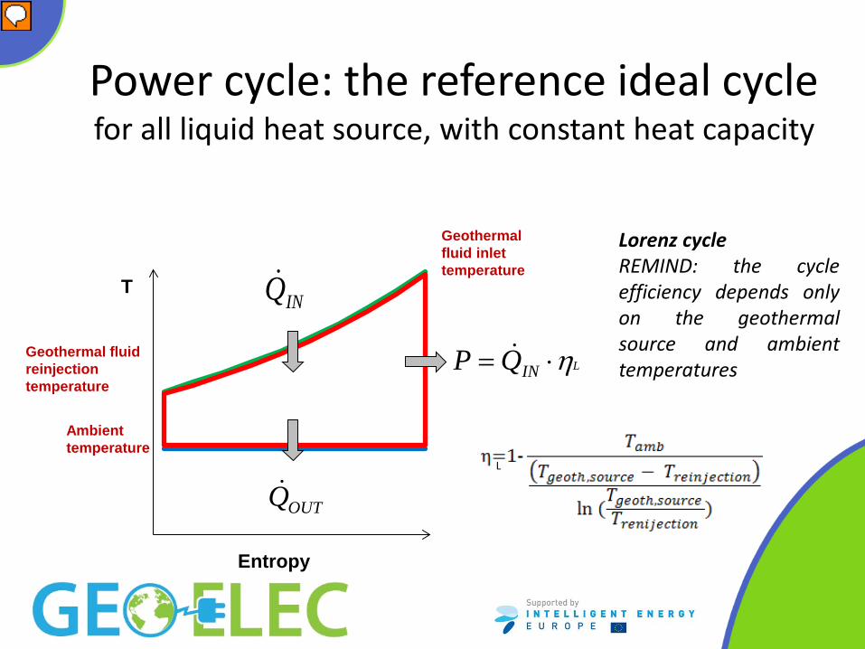
Power cycle: the reference ideal cycle for all liquid heat source, with constant heat capacity
Entropy
LINQP η⋅= Geothermal fluid reinjection temperature
Ambient temperature
T
Geothermal fluid inlet temperature
OUTQ
INQLorenz cycle REMIND: the cycle efficiency depends only on the geothermal source and ambient temperatures
L
Relatore
Note di presentazione
Serve x calcolare eta rif
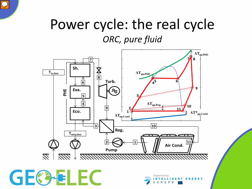
Power cycle: the real cycle ORC, pure fluid
Turb.
Reg.
Pump
Eva.
Eco.
Sh.
Air Cond.
4
3
2 1
6
7
8
9
10
5
11
2
ΔTap,Cond
3
45 6
7 8
9
1011
PHE
Tin,Geo
Treinj,Geo
ΔT*pp,Cond
ΔTap,PHE
ΔTpp,PHE
ΔTpp,Reg
1
Relatore
Note di presentazione
N.B. importanza DT pinch point;
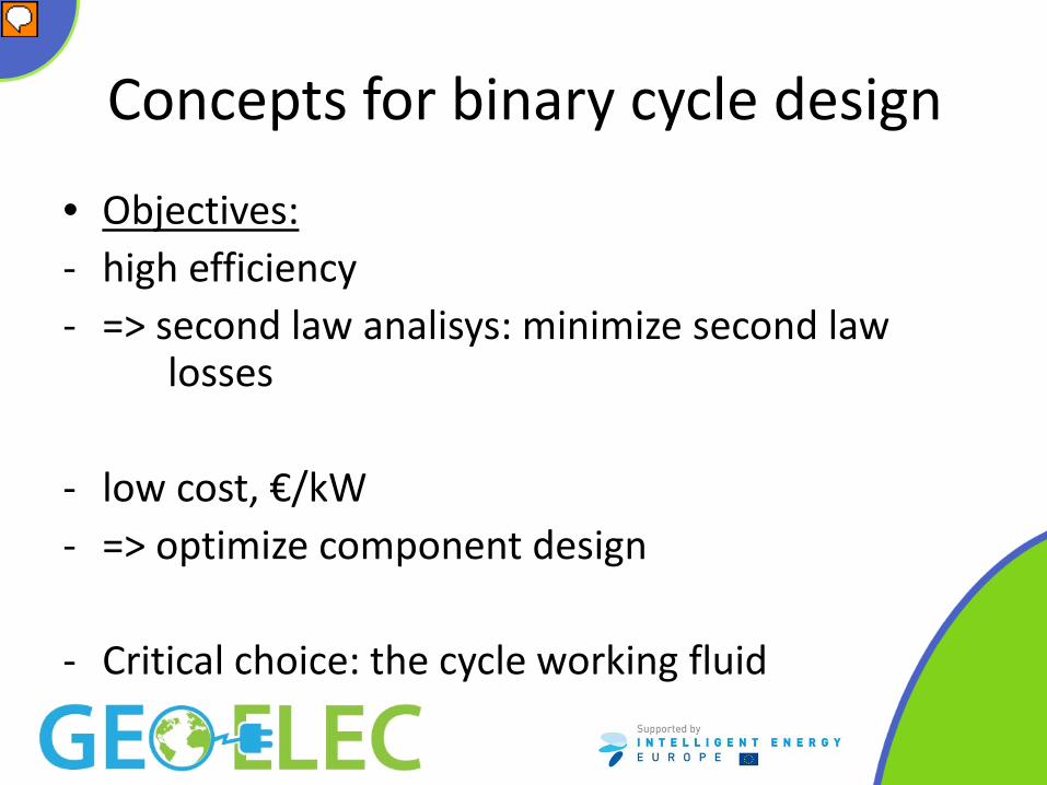
Concepts for binary cycle design
• Objectives: - high efficiency - => second law analisys: minimize second law
losses
- low cost, €/kW - => optimize component design
- Critical choice: the cycle working fluid
Relatore
Note di presentazione
The working fluid must allow high efficiency and low cost sizing of components
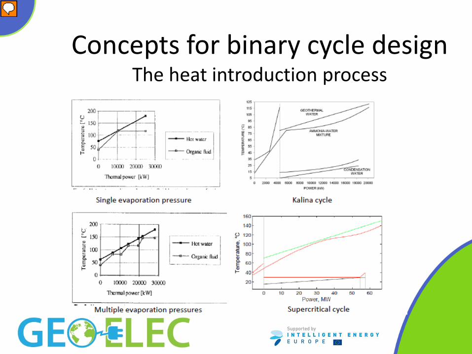
Concepts for binary cycle design The heat introduction process
Relatore
Note di presentazione
NB 3 sono ORC; poi ci sono i cicli triangolari e/con flash
ORC working fluid selection
• The fluid must be suitable for the selected geothermal source and plant size (Fluid critical temperature and pressure, molecular complexity and mass are relevant)
• Hydrocarbons • Refrigerants • Others Important issues: environmental, toxicity, flammability, material and lubricant compatibility, cost
Relatore
Note di presentazione
Boss ORC2013: molec complexity (numb of atoms) relevant for the shape of Andrews curve (possible dry expansion) Molec mass relevant for stage delta h and heat transfer (low if mass high) Pcond x component sizing Large flow rate, large D turbine, no erosion The three groups of F-gases are hydrofluorocarbons (HFCs), perfluorocarbons (PFCs) and sulphur hexafluoride (SF6) F-gases account for 2% of the EU's overall greenhouse gas emissions, but F-gas emissions have risen by 60% since 1990 – in contrast to all other greenhouse gases, which have been reduced F-gases can remain in the atmosphere for thousands of years. Equipment and appliances containing F-gases can have long lifetimes of up to 50 years Figura con fluidi ottimi nel piano T geo Tcr? Alkanes: Propane, Isobutane, Butane, Neopentane, Isopentane, Pentane, Isohexane, Hexane, Heptane, Octane, Nonane, Decane Other hydrocarbons: Cyclopropane, Cyclopentane, Cyclohexane, Methylcyclohexane, Propylcyclohexane, Isobutene, 1-Butene, Trans-Butene, Cis-Butene, Benzene, Propyne, Methanol, Ethanol, Toluene, Acetone, Dimethylether HFC: R125, R143a, R32, R1234yf, R134a, R227ea, R161, R1234ze, R152a, R236fa, R236ea, R245fa, R365mfc FC: R218, Perfluorobutane (C4F10), RC318 Exergy usa C6F14: PERFLUORO -2-METHILPENTANE Siloxanes MM, Mdm, Md2m, Md3m, Md4m, D4, D5, D6 Exergy usa C6F14: PERFLUORO -2-METHILPENTANE
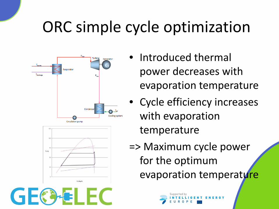
ORC simple cycle optimization
• Introduced thermal power decreases with evaporation temperature
• Cycle efficiency increases with evaporation temperature
=> Maximum cycle power for the optimum evaporation temperature
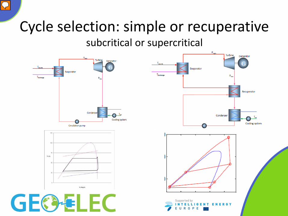
Cycle selection: simple or recuperative subcritical or supercritical
Relatore
Note di presentazione
NB margine raffredd sorgente
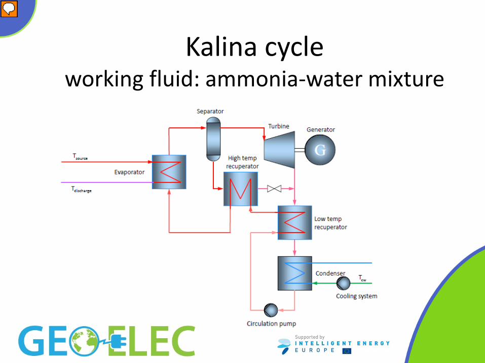
Kalina cycle working fluid: ammonia-water mixture
Relatore
Note di presentazione
Metti storia Kalina: da CC a OTEC Finally, this analysis demonstrates that broad claims of 15–50% more power output for the same heat input for Kalina cycles relative to organic Rankine binary cycles are not being achieved for plants in operation. Under simulated identical conditions of ambient temperature and cooling systems, the calculated difference in performance is about 3% in favor of a Kalina cycle. It is uncertain whether the difference in inlet brine exergy favoring the Kalina cycle in this study may have played a role in the efficiency advantage of the Kalina over the ORC. It must be pointed out that ORC geothermal technology is mature, with hundreds of megawatts of various kinds of cycles installed throughout the world, whereas the Húsav´ık plant is the only commercial Kalina cycle in operation so far.
Cost & component sizing
• Turbine sizing • Selection of ∆Tpinch point for the heat exchangers:
the smaller the ∆Tpinch point , the higher the efficiency but also the heat exchanger cost
Relatore
Note di presentazione
Turbine is crucial for cycle efficiency and cost; the choice of a proper working fluid allows an effective turbine sizing Even with with a “perfect ideal” fluid, no way to catch to hot source curve, it would bring to infinite surface for heat exchangers
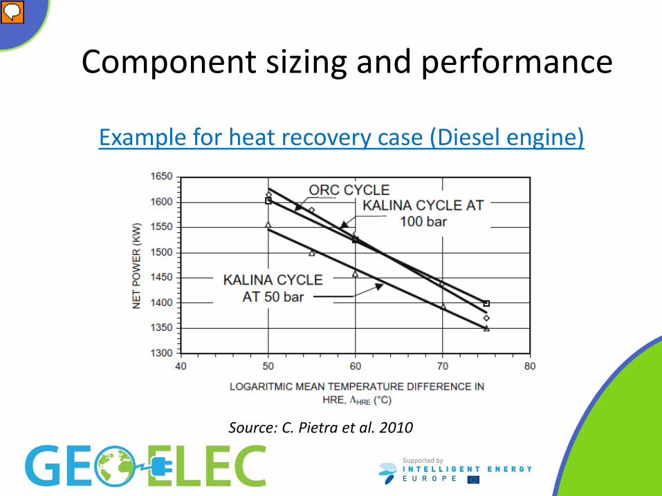
Component sizing and performance
Source: C. Pietra et al. 2010
Example for heat recovery case (Diesel engine)
Relatore
Note di presentazione
Even with with a “perfect ideal” fluid, no way to catch to hot source curve, it would bring to infinite surface for heat exchangers
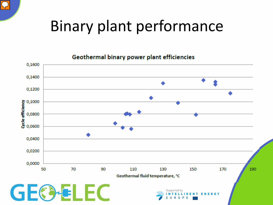
Binary plant performance
Relatore
Note di presentazione
DI PIPPO: Geothermal binary plants are relatively poor converters of heat into work. First Law or thermal efficiencies typically lie in the range of 8–12%. The results show that binary plants can operate with very high Second Law or exergetic efficiencies even when the motive fluids are low-temperature and low-exergy. Exergetic efficiencies of 40% or greater have been achieved in certain plants with geofluids having specific exergies of 200 kJ/kg or lower. The main design feature leading to a high Second Law efficiency lies in the design of the heat exchangers to minimize the loss of exergy during heat transfer processes. Another important feature that can result in a high Second Law efficiency is the availability of low-temperature cooling water that allows a once-through system for waste heat rejection. Finally, this analysis demonstrates that broad claims of 15–50% more power output for the same heat input for Kalina cycles relative to organic Rankine binary cycles are not being achieved for plants in operation. Under simulated identical conditions of ambient temperature and cooling systems, the calculated difference in performance is about 3% in favor of a Kalina cycle. It is uncertain whether the difference in inlet brine exergy favoring the Kalina cycle in this study may have played a role in the efficiency advantage of the Kalina over the ORC. It must be pointed out that ORC geothermal technology is mature, with hundreds of megawatts of various kinds of cycles installed throughout the world, whereas the Húsav´ık plant is the only commercial Kalina cycle in operation so far.
Turbine requirements: • Work extraction • Suitability to accomodate increasing volumetric
flow rate • High efficiency • Low cost (=> reduced stage number) Remark: dry vapour expansion, no erosion of blades
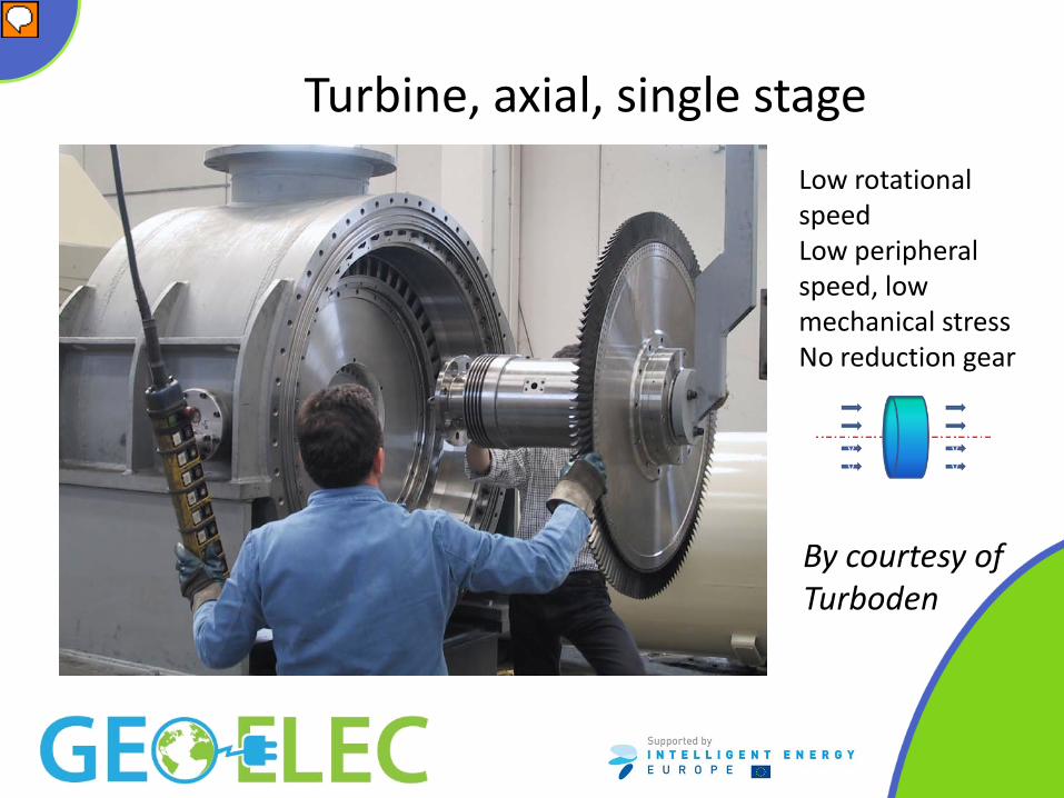
Binary power plant – turbine
• Axial, possibly multistage most common • Radial, inflow, usually single stage sometimes used
• Radial, outflow, multistage recently proposed again
Relatore
Note di presentazione
Assiale è facile multistadio La radiale centripeta se basta uno stadio bene, altrimemnti metterne due in serie non è banale La velocità di rotazione delle turbine Ormat è spesso (ma non sempre, si vedono anche molti riduttori) 1500-1800 rpm, cioè con accoppiamento diretto a generatori a quattro poli a 50 o 60 Hz. TD predilige il due poli asicrono, per cui i giri sono effettivam appena sopra a 3000. Le turbine radiali inflow di solito sono veloci e hanno un riduttore che alimenta un generat a 4 poli.. I generatori veloci a velocità variabile penso che siano pochi, a differenza dell'eolico il vantaggio nel cambiare la vel periferica è modesto. Dal sito Exergyntroducing the radial outflow turbine The radial outflow turbine designed and produced by Exergy is unique in the ORC market. From an inspiration in the 2010 of our CEO – Claudio Spadacini, we reinvented this technology and for the first time we took it to compete in the ORC field with the well-known axial and radial inflow configurations. This type of turbine has been used since late nineteenth century in traditional steam Rankine, known as Ljungstrom, Parsons or Siemens turbine, but suffered the competition of axial turbines due to technological issues that have been easily overcome in the ORC application. The radial outflow turbine is capable of processing low enthalpy drop on a single stage, thus when it is applied to a steam Rankine cycle tens of stages and multiple disks are needed. On the other hand this technology is optimal for the organic Rankine cycle, as through a limited number of stages on the same disk the turbine can process the entire available enthalpy drop. Advantages Working with an organic fluid most of the characteristics of the radial outflow turbine become advantageous as summarized below: Excellent match of the volumetric flow and the cross section across the radius ; No need for partial admission ; Constant velocity diagrams across the blade due to prismatic blades ; Less tip leakages and disk friction losses ; Tip speed is limited by the low speed of sound. All this leads to a more efficient machine, rotating at low revolving speed and having very low vibrations and noise level. Our ambitious theoretical calculations has been entirely confirmed by field measures and now as first and only we can offer you proven solution, competitive with the existing technologies on capital expenditure as well as on operating costs thanks to its simple construction and easy operation and maintenance.
Fino a 10-15 MW Low mechanical stress of the turbine due to the low peripheral speed Low RPM of the turbine allowing the direct drive of the electric generator without reduction gear
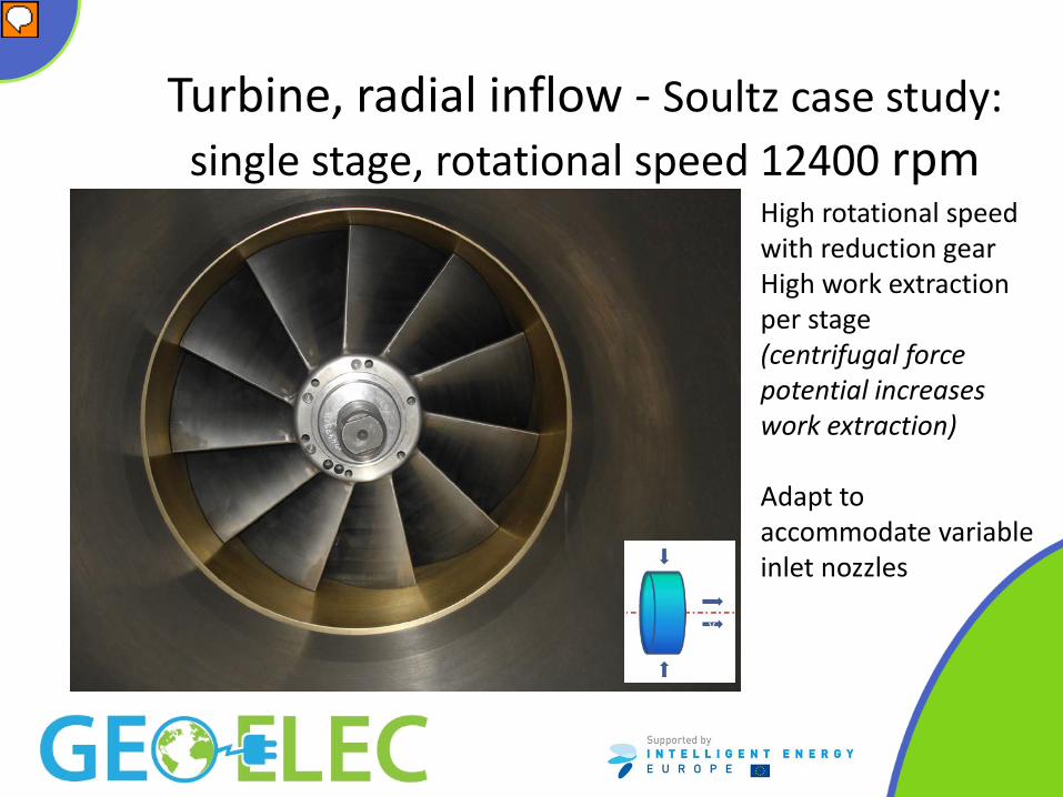
Turbine, radial inflow - Soultz case study: single stage, rotational speed 12400 rpm
High rotational speed with reduction gear High work extraction per stage (centrifugal force potential increases work extraction) Adapt to accommodate variable inlet nozzles
Relatore
Note di presentazione
Perdite grandi nei cuscinetti e nelle tenute
Turbine, radial inflow - Soultz case study
Binary power plant – turbine radial, outflow, multistage
Fluid passage area naturally increases along the expansion process Low work extraction per stage (centrifugal force potential acts against work extraction) High number of stages required Low rotational speed, no reduction gear
Relatore
Note di presentazione
Relatively low Mach number, profile aerodynamics crucial for energy exchange effectiveness M. Pini et al, - Preliminary design of a centrifugal turbine for ORC applications, ORC 2011, First International Seminar on ORC Power Systems Turb Exergy va a 3000 rpm (Asto) The turbine sold now is a key component in the supply of a complete Organic Rankine Cycle binary power plant for Turkish company AKÇA ENERJ?, to be installed in the region of Denizli. The AKÇA unit will have a power output of 3.5 MWe when it becomes operational in October 2014. The Turkish geothermal market has become one of the world’s most important in recent years, and this ‘low enthalpy’ project (the resource is only slightly more than 100°C) is forecast to be the first of many such projects within the region. EXERGY provide a unique solution for the low enthalpy market, which lead to higher efficiency at a reasonable price. This is due to the unique capability of the radial outflow turbine to accommodate more than one pressure level entry on a single turbine. These multiple pressure systems are particularly suited to low enthalpy projects, where they can produce up to 20% more power than single pressure systems generated by competitor turbines. [source Thinkgeoenergy website]
Binary plant – power cycle pump
• Centrifugal, multistage pump
• Operated at variable speed
Power Plant - Heat Exchangers shell and tube or plate – possibly with phenolic coating
Soultz heat exchangers
Relatore
Note di presentazione
Preriscaldatore ed evaporatore
Heat Exchangers – Soultz case study
Soultz T-Q diagram
Operation & Maintenance
• Plant remote control • Monitoring of measured values • - Physical (p, T, flows, …) • - Mechanical (vibrations) • - Electrical • Check of power plant pump and turbine sealing • Heat exchanger cleaning • Check of down hole pump and periodic pump substitution • brine acidification, scale inhibitors • Operation supplies (chemical for cooling water, inhibitors,
lubricating oil, filters )
Relatore
Note di presentazione
Su O&M di solito il carico di manutenzione riguarda soprattutto il circuito geotermico e la pulizia delle superfici di scambio lato fluido geo, l'ORC in sè richiede solo piccole verifiche, pulizia di filtri e cose del genere, per qualche ora/sett più un intervento con fermata breve della macchina programmato nell'anno. Dal punto di vista dell’esercizio gli aspetti più critici riguardano le pompe in pozzo (in particolare le ESP, con motore in pozzo) e le tenute su pompa di alimento del fluido e turbina o espansore. Per quanto riguarda le ESP, la vita utile è intorno ai 2-3 anni; per massimizzare la vita occorrono l’azionamento tramite inverter o almeno soft-start per evitare shock meccanici sulla linea d’asse. Un altro punto critico delle ESP è la connessione dei cavi al motore; su questo punto ti allego una presentazione Schlumberger sulla loro soluzione innovativa. Le tenute su pompa ed espansore sono critiche perché sono i punti ove è più probabile accadano perdite; oramai si utilizzano tenute meccaniche doppie. Ti allego un foglio Excel dove trovi l’elenco dei controlli e delle manutenzioni programmate sul nostro impianto di Salt Wells (con espansori centripeti Atlas-Copco); non puoi diffonderlo, ma puoi trarci qualche spunto interessante.
Bibliography • Di Pippo, Ronald: Geothermal Power Plants: Principles, Applications, Case
Studies and Environmental Impact, Elsevier Science, Dartmouth, Massachusetts, (2007).
• Technology Platform on Geothermal Electricity (TP-Geoelec) “Strategic Research Priorities for Geothermal Electricity» available on the Internet at: www.egec.org
Bibliography • Bombarda, P., Gaia, M., Pietra, C., “Integration of Geothermal Liquid
Dominated Sources and Waste Heat Sources for Electricity Production”, Proceedings of the “World Geothermal Congress 2010, Bali, Indonesia
• Pini, M., Persico, G., Casati, E., Dossena, V., “Preliminary design of a centrifugal turbine for ORC applications”, Journal of Engineering for Gas Turbines and power, vol. 135, n°4, april 2013
• Invernizzi, C., “Closed power cycles. Thermodynamic Fundamentals and Applications. Series: Lecture Notes in Energy, Vol. 11, Springer