maharashtra state board of technical · pdf file1 summer – 13 examination subject...
TRANSCRIPT
1
SUMMER – 13 EXAMINATION
Subject Code:12190 Model Answer
Important Instructions to examiners:
1) The answers should be examined by key words and not as word-to-word as given in the
model answer scheme.
2) The model answer and the answer written by candidate may vary but the examiner may try
to assess the understanding level of the candidate.
3) The language errors such as grammatical, spelling errors should not be given more
Importance (Not applicable for subject English and Communication Skills).
4) While assessing figures, examiner may give credit for principal components indicated in the
figure. The figures drawn by candidate and model answer may vary. The examiner may give
credit for any equivalent figure drawn.
5) Credits may be given step wise for numerical problems. In some cases, the assumed constant
values may vary and there may be some difference in the candidate’s answers and model
answer.
6) In case of some questions credit may be given by judgement on part of examiner of relevant
answer based on candidate’s understanding.
7) For programming language papers, credit may be given to any other program based on
equivalent concept.
MAHARASHTRA STATE BOARD OF TECHNICAL EDUCATION
(Autonomous)
(ISO/IEC – 27001 – 2005 Certified)

2
Q1) A) Attempt any three (12)
a) List CCIR(B) standards for colour TV (any 8)
Ans : (4)
Sr. No. Parameters Values
1. Number of lines per frame (Picture) 625
2. Aspect ratio 4:3
3. Line frequency 15625 Hz
4. Field frequency 50 Hz
5. Picture frequency 25 Hz
6. Interlace ratio 2/1
7. Scanning sequence (1) Line : left to right
(2) Field : Top to bottom
8. Nominal video bandwidth 5 MHz
9. Channel Bandwidth 7 MHz
10. Type and polarity of video modulation A5C AM negative
11. Sync level as percentage of peak carrier 100%
12. Type of sound modulation F3FM
13. Pre-emphasis 50 µ sec
14. Resolution 400 max
b) Write advantages of Fluorescent Display System used in CD Player.
Ans : Advantages of Fluorescent Display : (any 4) (4)
i) Emits a very bright light with clear contrast.
ii) Easily support display elements of various colours.
iii) The light produced by most VFDs contain many colours and can often be filtered to
produce a more pure colour such as deep green or deep blue.
iv) Being rugged, inexpensive.
v) Easily configured to display a wide variety of customized messages.
vi) Most VFD’s continue to function normally in sub zero temperatures making them
ideal for outdoor devices in cold climates.
c) Explain the terms Hue, Saturation, Aspect-ratio and Flickers.
Ans : (1)
Hue - This is the predominant spectral colour of received light which means it is the actual
colour seen by the eye. Red, Green, Blue, Yellow, Magenta, represent different in the visible
spectrum.

3
Saturation – (1)
It represents the spectral purity of a colour light. It is the amount of white light that is
mixed with a colour.
A fully saturated colour will have no white light mixed with it.
For example, a Pure Red without White is a saturated colour.
Aspect ratio – (1)
The width to height ratio is defined as the aspect ratio.
It is fixed at 4:3 i.e. width = 4 and height = 3
Flickers - (1)
When scanning beam flips from bottom to top of the picture frame, it takes about some used time.
This retrace of some used duration is blanked on screen of the picture tube and so the screen
appears blank during this period. When programme is being displayed, dark interruption of
blanking between bright picture appears called as flicker.
d) Draw and describe operation of graphic equalizers.
Ans : Graphic equalizer is used to eliminate unwanted peaks in the frequency response (2)
of audio systems.
In five point configuration, the graphic equalizer breaks up an audio input signal into five
different bands covering the range of human hearing. Once this is completed, the signal in
each band can be adjusted to provide best sound. The center frequencies f1, f2, f3, f4 and f5
of the frequency bands of the graphic equalizer are usually fixed at pre-set values. Once
these bands are added back together, they are passed through an amplifier which increases
the amplitude of the signal to the point where there is enough power that can be heard
through an ordinary speaker.
The circuit diagram of graphic equalizer is shown in figure. The graphic equalizer
consists of an amplifier for every segment of octave band. Such amplifiers are connected
in parallel to cover the complete frequency range.
The individual gains of these amplifiers are adjusted such that the required frequency
response is obtained. Using five amplifiers for five octaves of frequency may be very
expensive. Hence amplifier shown in figure is normally used.

4
Diagram (2)
Graphic Equalizer
The figure shows, there is only one amplifier with multiple feedback paths. There are gain
controls and LC tuned circuits in every feedback path. Thus the gain of every octave band
is separately adjusted by the corresponding feedback path gain.
The center frequency of the octave band is selected by inductors L1, L2, L3, L4 and L5.
The gains of individual octave bands are adjusted by potentiometer controls in the
feedback path.
The combination of individual control setting for various octaves will provide the required
frequency response. The peaks at individual octave bands overlap each other. Hence,
phasing distortion needs to be avoided. This distortion occurs due to interaction between
the overlapping peaks. The slider controls of each octave band can boost or cut the signals
from +15 dB to – 15 dB.

5
B) Attempt any one (6)
a) Draw the block diagram of Monochrome TV. Describe its operation.
Ans : Diagram (3)
Block diagram of Monochrome TV
OR
Block diagram of Monochrome TV Transmitter
6
Block diagram of Monochrome TV Receiver
(3)
At the TV studio, the TV camera focuses on optical image of the scene on its
photosensitive plate and the picture elements of varying light intensity are converted into
correspondingly varying electrical signals by a process of electronics scanning.
The electrical signals so formed by scanning the picture imager by an electric beam are
called Video Signals. At this stage certain synchronizing signals meant to keep the
reassembly of the picture at the receiver in step with the scanning at the studios are also
added to the video information.
The composite video signal so formed is amplified by Video Amplifiers and made
sufficiently strong to Amplitude Modulate a picture carrier wave which is transmitted by
the transmitting antenna.
7
The sound picked up by the microphone is converted into electrical currents called Audio
signal of frequencies (20 hz to 20 kHz) and is strengthened by the audio amplifier which
frequency modulates a separate RF carrier whose frequency is generally 5.5 MHz above
the Frequency of the Video Carrier. The frequency modulated (FM) sound carrier is
radiated by the same transmitting antenna as used for the transmission of the video or
picture carrier.
Thus at the TV transmitting station, two separate RF carriers, one for the transmission of
picture signals and the other for sound signals are radiated by a common transmitting
antenna. The picture (video) carrier is Amplitude Modulated and the sound carrier is
Frequency Modulated.
Two separate RF carriers are used for video and audio transmission. The power output of
the picture and sound transmitters are combined in a Diplexer and fed to a common
transmitting antenna system to be radiated together.
Frequency Modulation is used for sound transmission and Amplitude Modulation is used
for picture transmission.
At the receiving end, both the picture and sound carriers are intercepted by the same
receiving antenna and passed onto a wide band circuit called the Tuner. The Tuner
consists of the RF Amplifier, Mixer and Local Oscillator. In the Tuner two separate
Intermediate Frequencies (IFs) for picture and sound signals are formed by Heterodyning
(mixing) with a local oscillator as in a Superheterodyne receiver.
The picture and sound IF Frequencies are amplified by a common IF amplifier and then
detected by the Video Detector. At this stage, the sound IF OF 5.5 MHz (the difference
between video and sound IF from the tuner) is separated and fed into the sound channel
where it is detected by a method of FM detection and the AF signal is amplified and fed
into the speaker to produce the sound as in a normal FM receiver.
The video signal from the video detector stage is amplified by a video amplifier and is
used to modulate the electron beam in the picture tube to produce a picture on the
televised scene.
A portion of the composite video signal is also fed to a Synchronising Separator where the
synchronizing signals are separated from the video signal and applied to the deflection
circuits (vertical and horizontal deflection) to keep the electronics scanning beam in the
picture tube in step with the electron beam at the transmitter.
The method of obtaining the sound IF (5.5 MHz) by beating or mixing the video IF (38.9
MHz) and sound IF (33.4 MHz) carriers is known as the Inter-Carrier Sound System. This
method is used in all the modern system used in TV receivers.

8
b) Draw the block diagram of Colour TV Transmitter.
Ans : (6)
Block diagram of Colour TV Transmitter

9
c) Draw and explain block diagram of Colour TV receiver.
Ans : Diagram (3)
Block diagram of Colour TV receiver
(3)
A colour TV receiver contains all the necessary circuits of a monochrome receiver plus
additional circuits required for the reproduction of a coloured picture.
Basically a colour TV receiver is a black-and-white receiver with a decoder for the colour
signals and a colour picture tube.
The figure is the functional block diagram of a colour TV receiver.
The block diagram shows that the circuits like the RF tuner, VIF amplifier, the video
amplifier, the deflection sync, the sweep circuits and the EHT sections are virtually the
same as in black-and-white receiver.

10
However there are some minor differences in design and details. For example the RF
response in case of colour TV is kept more uniform than in monochrome receiver, this is
to avoid any attenuation of the colour sub-carrier.
The tuning of a colour TV is critical. To avoid any mistuning of the receiver, an
arrangement called AFT (Automatic Fine Tuning) is used in most cases. This
arrangement is similar to the AFC and can be switched off whenever manual tuning is
required.
The colour TV uses theintercarrier sound system with one difference. The sound take-off
point is at the last VIF stage immediately before the video detector. This is done to avoid
interference between the sound IF and the chroma signal.
A separate diode detector is used to produce the sound IF but the rest of the audio circuits
are the same as in a monochrome receiver.
The two main circuits which distinguish a colour TV from a monochrome TV are the
colour picture tube and the chroma section containing the colour circuits.
Q2) Attempt any four (16)
a) Draw and explain block diagram of CCTV system.
Ans : Diagram (2)
Block diagram of CCTV system
Closed Circuit Television (CCTV) : (2)
Closed Circuit Television (CCTV) are used for industrial applications, security and
surveillance, education and training, public information displays and many others. In
some of the above mentioned applications CCTV are characterized by less complex
circuitry and low cost where professional grade broadcast standards are not required.
In CCTV the pick up camera tubes generally used are vidicon for industrial and medical
X-ray applications, plumbicon is used for high light applications, multidiode silicon
vidicon and charge coupled device camera are used for security and surveillance.
Solid state circuitry is used in the camera unit and the display units. Considerable
simplification is possible due to random interlace system and less simple type signal
waveform called as ‘industrial sync’.

11
In case of closed circuit television the composite video signals are not modulated. They
are directly fed to the video receivers. CCTV does not follow the television broadcast
standards. The block diagrams for direct camera link and wireless link are as shown in
figure.
b) Compare NTSC, PAL, SECAM System (4 points)
Ans : (4)
Sr.
No.
Parameter PAL NTSC SECAM
1. Full form of system Phase Alternation of
Line
National Television
System Committee
Sequential Colour A
Memory
2. Inventing country. Germany in 1967 USA in 1957 France in 1970
3 Countries where
used.
Germany, India, UK USA, Canada,
Japan, Mexico.
France, East Europe,
Africa.
4 Transmission of
colour.
By colour difference
signals.
By colour
difference signals.
By colour difference
signals.
5 Video bandwidth. 5 MHz 4 MHz 6 MHz
6 Noise High High Very high.
7 Identification signal Needed Not needed Needed
8 Cost Costliest Less than PAL but
higher than
SECAM
Cheapest
c) Write 2 merits and 2 demerits of Negative Modulation.
Ans :
Merits : (any two) (2)
1. Lesser noise interference on picture signal.
2. Possible to obtain larger peak power output.
3. Less picture signal distortion.
4. Easy to develop true AGC voltage.
5. More efficient operation.
Demerits : (2)
1. The synchronization of the receiver is affected by spurious random pulses producted due
to the effect of noise.
2. The loss of horizontal and vertical synchronization may cause diagonal or vertical rolling
of picture.

12
d) What is Interlace Scanning ? Write its advantages.
Ans : Diagram (2)
(1)
In television pictures an effective rate of 50 vertical scans per second is utilized to reduce
the flicker. This is accomplished by increasing the downward rate of travel of the
scanning electron beam, so that every alternate line gets scanned instead of successive
line.
Then when the beam reaches the bottom of the picture frame it quickly returns to the top
to scan those lines that were missed in the previous scanning.
Thus, the total number of lines are divided into two groups called ‘fields’. Each field is
scanned alternately. This method of scanning is called interlaced scanning’.
In the 625 line TV system, for successful interlaced scanning, the 625 lines of each frame
or picture are divided into sets of 312.5 lines and each set is scanned alternately to cover
the entire picture area.
To achieve this, the horizontal sweep oscillator is made to work at a frequency of 15625
Hz (i.e. 312.5 x 50 = 15625) to scan the number of lines per frame, but the vertical sweep
circuit is run at a frequency of 50 Hz (i.e. 25 x 2 = 50Hz)
Note that since the beam is now deflected from top to bottom in half the time and
horizontal oscillator still operating at 15625 Hz, only half the total lines (i.e. 312.5) get
scanned during each vertical sweep.
13
Since the first field ends in a half line and the second field starts middle of the line on top
of the screen, as shown in fig., the beam is able to scan the remaining 312.5 alternate lines
during its downward journey.
The beam scans 652 lines per frame at the same rate of 15625 lines per second. Therefore,
with interlaced scanning the flicker effect is eliminated without increasing the speed of
scanning, which in turn does not need any increase in channel bandwidth.
Advantages : (1)
1) It reduces the video bandwidth.
2) It minimizes the flickering or jittering.
e) State and explain working principle of Dish Antenna.
Ans : (2)
The main function of dish antenna is to receive the signals from the satellite. The signals
are concentrated towards the center of dish antenna where a feed horn is present. For this
reason parabolic shaped fish antennas are commonly used. Dish antennas from 4 to5
meters to as large as 30 meters are present for receiving the signals.
The figure shows the receiving station antenna with a parabolic reflector and the Low
Noise Block Down Converter (LNBC) unit mounted at the focal point of the parabola.
As seen in fig. the parabolic reflector receives the electromagnetic waves from the
satellite.
As seen in fig. all the waves are reflected from the parabola and are received at the focal
point. The parabolic dish gives a high gain to the antenna.
The parabolic reflector collects all the electromagnetic waves from satellite due to
parabolic shape reflected rays concentrate at focal point which gives the high gain signal.
The ratio of the focal length to the mouth diameter is called aperture of the parabola just as
in camera lenses.
The reflector provides a high gain because like the mirror of a reflecting telescope, it
collects radiation from a large area and concentrates it all at the focal point.
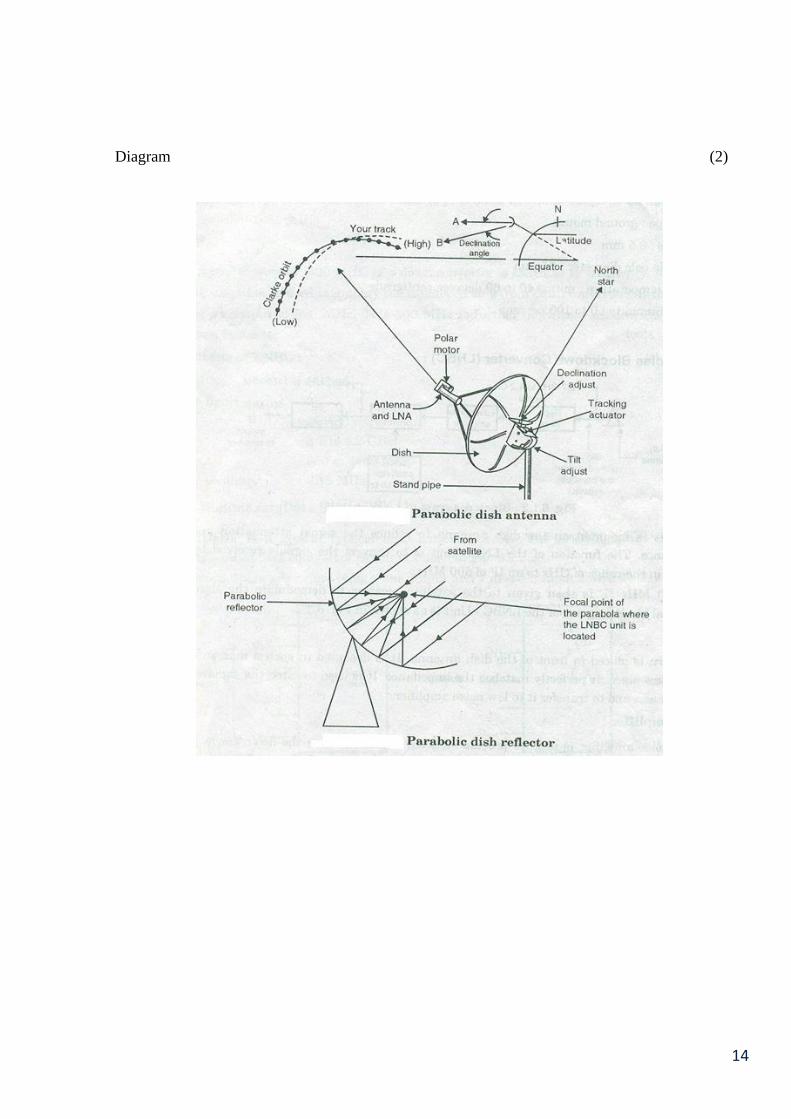
14
Diagram (2)

15
Q.3 Attempt Any Four (16)
(a)Compare additive maxing and subtractive mixing of colours.
(EACH POINT ONE MARKS 1*4) 4 MARKS
Ans. Additive Colour Mixing Subtractive Colour Mixing
1. Additive mixing of three primary
colours red, green and blue with
proper proportions can create any
colour.
1. In subtracting mixing
reflecting properties of
pigments are used which
absorb all wavelengths but for
their characteristics colour
wavelengths.
2. Different colours are created by
mixing pure colours hence used in
TV.
2. Different colourscreated by
subtracting parts from white so
not suitable for TV.
3. For example,
Red + Blue = Magneta
Red + Green = Yellow
Green + Blue = Cyan
3. For example,
White – Green = Magneta
White – Blue = Yellow
White – Red = Cyan
4. Additives primaries are Red,
Green, Blue.
4. Subtractive primaries are
Magneta, Yellow, Cyan.
Q.3 (b) Explain principle and working of Vidicon Camera Tube.
(DIAGRAM 2 MARKS,PRINCIPLE 1 MARKS,WORKING 1 MARKS) 4 MARKS
Ans.
Vidicon Camera Tube
The vidicon tube operates on the principle of photo conduction.
When light falls on a photo conductive plate, the conductivity of target plate varies
accordingto the intensity of light falling on target plate, this is called as photo conduction.
It makes use of the photo conductivity of certain semiconductor material as antimony
tri-sulphite.

16
The photo conductive material is a semiconductor changing with light and storing small are
of charge.
The target of the tube consist of transparent film of conducting surface.
It has just photo conductivity layer target plate and the e gun along with focusing and
scanning coil with optical image focused on the target.
It produces a charge image that is scanned by e form the gun to develop video signal across
a load resistor.
This video signal obtained is proportional to the optical image.
Thus the camera tube goes through 2 function i.e. conversion of optical image into charge
image and charge image is scanned to produce video information.
Q.3
(c)
Compare stereo amplifier with mono amplifier.( Any four points)
(EACH POINT 1 MARKS) 4 MARKS
Ans. Stereo amplifier
Mono amplifier
1. As the name suggest, the basic
stereophonic system has two
separate channels after the pre
amplifier stage.
1. There is only one channel
after pre amplifier stage.
2. Stereophoic sound is created by
two independent audio channels
to provide sense of direction
2. Sense of direction is not
pronounced as in
stereophonic amplifier.
3. Consists of two preamplifiers
power amplifiers and loud
speakers
3. Consists of one preamplifiers
tone and volume controls,
power amplifier.
4. Stereophony creates the
impression of sound heard from
various directions as in natural
hearing
4. In monophonic or ‘mono’
sound, the audio is in the
form of one channel, often
centered in the sound field.
5. Less signal to noise ratio 5. Better than 50 dB is the S/N
ratio.
6. Non-linear distortion occurs. 6. Non-linear distortion not
more than input/output.
7. Equalizers are not used 7. Contains equalizer circuit.
8. Two-way cross-over network
with gain control exist.
8. Three-way cross-over
network exist.
Q.3 (d) List material used in CD player & explain any one of them.
(Note - It should not be material, it should be component.)
(LIST 2 MARKS,EXPLAINATION OF ANY ONE LISTED BELOW 2 MARKS)
4 MARKS
Ans. Different components used for CD mechanism.
1. CD-Pick-up assembly
2. CD Lens :
- Collimation lens
- Concave lens
- Objective lens
- Cylindrical lens
3. Gear system
4. Drive motors
- Tray, loading motor
- Slide, sled, feed motor
- Spindle, disc, turntable motor.

17
Pick up assemble :
The pick-up assemble consist of –
A low power laser diode to illuminate the CD tracks.
Lens and prism arrangement to direct the laser beam to the CD surface and to
direct the reflected laser beam towards photo-diode array.
A photo diode array to obtain data, focus and tracking signal from the reflected
laser beam.
Focus and tracking coils to focus the beam to the CD surface and to move the
assembly to proper track across the disc surface.
Some optical units do not contain the tracking coil, for example, the single-
beam radial tracking assembly, this is explained in latter sections.
Pick up assembly
Optical arrangement in a single-beam radial tracking pick-up assembly :
In the optical pick-up unit, the laser diode emits laser beam from a small point
into an elliptical or conical distribution. This beam is passed through various prism and
lens to form a very small diameter light beam on the disc surface at the centre of the
track.
The objective lens is controlled by the tracking and focusing coil to keep the beam
focused on the CD and to keep the condensed beam at the centre of the track.
This laser beam is reflected back by the flat area and the pits on the disc surface.
This reflected beam is applied to a group of photo-diodes through objectives lens,
collimator lens and some prism arrangement.
These photo-diodes induce voltage according to the reflected beam falling on it.
Focus error and tracking error voltage generated by this photo-diode array is applied
to the tracking and focusing coil to control the objective lens and data signal
generated by this photo-diode array is sent to an amplifier to amplify the data signals

18
picked-up from the disc. Finally, the output from the amplifier is processed to
produce the audio signal stored on the disc surface.
In a CD player the following type of optical assemblies are used:
Single-beam radial tracking
Single-beam linear/straight line tracking
Three-beam linear/straight line tracking.
“OR” CD Lens :
- Collimation lens:
The collimator lens is used to produce completely parallel beams of laser. This
lens together with the objective lens is used to focus the laser beam to the disc
surface.
- Concave lens:
In single-beam linear optical block assembly this concave lens is used to
concentrate the laser beam, reflected from the disc surface, onto the photo diode
array. This lens is mainly used to improve the sensitivity of the photo diode
array.
CD Lens
- Objective lens:
Before hitting the disc surface, the laser beam comes out the pick-up assembly through
an objective lens. The objective lens is used to focus, laser beam onto the CD surface
and to receive the reflected laser beam.
This lens is moved up/down to achieve the focus of the laser beam on the disc face.
The objective lens is always kept in focus using a system similar to the voice is system
used the audio speakers.
It is also moved horizontally in the linear pick-up assembly to keep the laser am in
proper track. In players that used the radial tracking method the objective is unit does
not move horizontally (laterally).
- Cylindrical lens (in Three-Beam Linear Optical Blocks)
The main action of this lens is to enable the reflected beam from the CD to assist in
creating the necessary signal to make sure that focus of the laser beam on the playing

19
surface the disc is maintained.
As shown in the fig. when the beam is correctly focused a circular beam of light will
land on the four photo-diode elements. If the beam becomes out of focus the
cylindrical lens will distort the beam elliptically. As shown in the fig. thetortion
depends upon the direction of mis-focus. This distortion is know as astigmatism.
OR ANY OTHER LISTED ABOVE.
Q.3 (e) Explain Yagi-Uda antenna and draw its radiation pattern.
(YAGI-UDA ANTENNA DIAGRAM 1 MARKS,RADIATION
PATTERN 1 MARKS,EXPLAINATION 2 MARKS)
4 MARKS
Ans. Yagi-Uda antenna is directional TV receiving antenna.
Yagi-Uda antenna is an array consisting of driven element and
one or more parasitic element.
Parasitic elements are reflector and director.
Driven element is known as dipole.
Function of each element
Director – Collects the maximum signal strengths. So the number of
directors are more than one. Director face towards transmitting
antenna.
Dipole – Collects all signal strength from directors and fed to TV
receiver through \Parallel wire.
Reflector :
Rejects unwanted signals from opposite side.
Yagi-Uda antenna
Q4 A) Attempt any TWO. (12)
(a)Explain the principle and working of delta gun picture tube.
(PRINCIPLE 2 MARKS,WORKING 2 MARKS,DIAGRAM 2 MARKS) 6 MARKS
Principle:
Electron beams from the guns strike three phosphor dots of traid. The dots of red , green and blue
phosphor in traid glow simultaneously , the intensity of glow being proportional to the intensity of
video signal of respective colour . the eye adds the three colour emitted by the phosphor dots at
time and perceives the resultant colour of the concerned pixel as the original picture.
The traids glow one after other in quick succession due to deflection of the beams and hence
whole picture is reproduced in its original colour
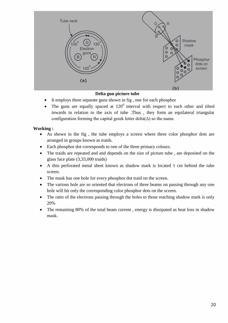
20
Delta gun picture tube
It employs three separate guns shown in fig , one for each phosphor
The guns are equally spaced at 1200
interval with respect to each other and tilted
inwards in relation to the axis of tube .Thus , they form an equilateral triangular
configuration forming the capital greek letter delta(∆) so the name.
Working :
As shown in the fig , the tube employs a screen where three color phosphor dots are
arranged in groups known as traids.
Each phosphor dot corresponds to one of the three primary colours.
The traids are repeated and and depends on the size of picture tube , are deposited on the
glass face plate (3,33,000 traids)
A thin perforated metal sheet known as shadow mark is located 1 cm behind the tube
screen.
The mask has one hole for every phosphor dot traid on the screen.
The various hole are so oriented that electrons of three beams on passing through any one
hole will hit only the corresponding color phosphor dots on the screen.
The ratio of the electrons passing through the holes to those reaching shadow mark is only
20%
The remaining 80% of the total beam current , energy is dissipated as heat loss in shadow
mask.

21
(b) Draw block Diagram of CD player and Write function of Each block.
(DIARAM 3 MARKS,EXPLAINATION OF EACH BLOCK 3 MARKS) 6 MARKS
Block Diagram of CD player
CLV:the CD player is also known as CLV or constant linear velocity system . In a CLV device
such as the CD player the rotational speed of disc player is adjusted with movement of reading
mechanism on the disc surface . This speed is changed to maintain constant linear velocity i.e. the
signal on the disc surface always moves at constant speed of 1.3 m per second under the pick-up
head.
Half-Full Memory: This half –full memory circuit makes the disc to maintain a constant linear
velocity when the reading mechanism moves from outer tracks of disc to inner tracks or from
inner tracks to outer tracks on disc surface.
Decoding CD: During the decoding , the digital data on the disc surface is read by the decoding
circuit and is converted Into the analog and 0 signal required to drive the speakers and regenerate
the stored music.
Optical pick-up: the signal stored on the CD surface as a pits and flat areas are first picked up by
the optical pickup made of lens assembly prism , photo detectors and laser diodes assembly in the
optical pick-up unit.
High frequency amplifier :the signal is very weak so it is amplified by a high frequency RF
amplifier circuit to bring signal to a proper level. This amplified and filtered high-frequency
signal contains audio signal as well as synchronization signal in 14-bit EFM (eight to fourteen
modulated)format , this signal is sent to an EFM demodulator circuit.
EFM Demodulator: The EFM modulator separates the modulated data and the timing signal
from the signal received at its input. It also removes the additional coupling bits and convert the
14-bit EFM symbol to actual 8-bit data. The amplified and filtered EFM signal from high
frequency amplifier is also given to clock generation circuit to synchronize detecting and timing
circuit. These circuits are used to recover the bit clock and sync pattern data .The timing separated
by this system is used to provide timing signal to the system.
ERCO Circuit: demodulated data from EFM demodulator is send to error correction
(ERCO)circuit. The demodulated data signals also send to control and display decoding circuit ,
which recovers the control and display signal received from CD .
Interpolation and muting :The ERCO circuit is used for error detection and correction purpose .
Any error found in the incoming data signal is send to interpolation and muting section by the
22
ERCO circuit . The interpolation and muting section uses the following methods to correct error
found in data stream read from the disc.
Muting
Last word held
Linear Interpolation
Muting: In muting , when error is detected in the data stream , the player will mute (silence)the
sound is not to send speaker .
CLV using the Clock Signal: The ERCO also responsible for maintaining constant linear
velocity of CD rotation motor , For this , The TRCO circuit compare the clock signal derived
from the incoming data with reference clock frequency.
De- interleaving :Signals from the ERCOcontains audio signal in theinterleaved format . before
doing any further operation on this signal , it must be interleaved . The signal Is then de-
interleaved in the interpolation and muting section to restore the original sequence of information.
Digital Filter and De-multiplexer: The de-interleaved and regenerated is then send to digital
filter and de-multiplexer , where it is filtered and separated in to left and right channel data. This
circuit removes any effect of sampling frequency from the data signal , which would appear as
interference in the form of aliasing noise in analog signal.
Oversampling: During digital filtering oversampling method is used to remove both problems of
aliasing noise and quantization error .
D/A convertor: The output from digital filter and de-multiplexer circuit is send to D/A
convertors. The right and left channels are processed by different D/A convertors . These
convertors convert the 16-bit digital signal into the original analog audio signal. Because of the
over sampling , done in the digital filter and de-multiplexer circuit simple low-pass filter is used .
Following the D/A process.
(c) Draw and explain the circuit diagram of RGB drive amplifier.
(CKT DIAGRAM 3 MARKS,EXPLAINATION 3 MARKS) 6 MARKS
Ans. RGB amplifier circuit consist of three identical video amplifiers for driving the 3 cathodes of
picture tube.The inputs of amplifiers obtained from the decoded red,green and blue outputs of
chroma IC. Q1,Q2,Q3 are high frequency transistor of type BF393 or BF 869. The 3 amplifiers are
of same design so their frequency response is nearly same. 3 amplifiers are identical so only 1 is
considered to explain.Q1 of green signal amplifier is connected in CE configuration. 150 V dc
supply is filtered by L2 and C9,C7 and C8 are bypass to the emitter supply.
R15 and R12 provide negative feedback to improve dc stability.L3 in the collector load used to
extend bandwidth.C1 at input to amplifier is to improve step response.
The d.c. collectorvoltage,determines the picture tube cut-off votage is fixed by R17.R1 is varied for
monochrome reproduction at high lights.

23
RGB drive amplifier
24
Q.4B
Attempt any ONE. (6)
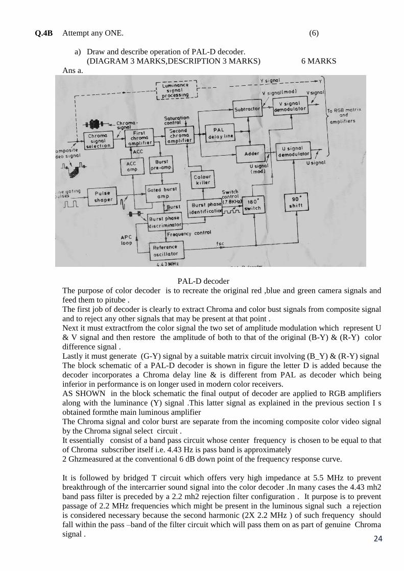
a) Draw and describe operation of PAL-D decoder.
(DIAGRAM 3 MARKS,DESCRIPTION 3 MARKS) 6 MARKS
Ans a.
PAL-D decoder
The purpose of color decoder is to recreate the original red ,blue and green camera signals and
feed them to pitube .
The first job of decoder is clearly to extract Chroma and color bust signals from composite signal
and to reject any other signals that may be present at that point .
Next it must extractfrom the color signal the two set of amplitude modulation which represent U
& V signal and then restore the amplitude of both to that of the original (B-Y) & (R-Y) color
difference signal .
Lastly it must generate (G-Y) signal by a suitable matrix circuit involving (B_Y) & (R-Y) signal
The block schematic of a PAL-D decoder is shown in figure the letter D is added because the
decoder incorporates a Chroma delay line & is different from PAL as decoder which being
inferior in performance is on longer used in modern color receivers.
AS SHOWN in the block schematic the final output of decoder are applied to RGB amplifiers
along with the luminance (Y) signal .This latter signal as explained in the previous section I s
obtained formthe main luminous amplifier
The Chroma signal and color burst are separate from the incoming composite color video signal
by the Chroma signal select circuit .
It essentially consist of a band pass circuit whose center frequency is chosen to be equal to that
of Chroma subscriber itself i.e. 4.43 Hz is pass band is approximately
2 Ghzmeasured at the conventional 6 dB down point of the frequency response curve.
It is followed by bridged T circuit which offers very high impedance at 5.5 MHz to prevent
breakthrough of the intercarrier sound signal into the color decoder .In many cases the 4.43 mh2
band pass filter is preceded by a 2.2 mh2 rejection filter configuration . It purpose is to prevent
passage of 2.2 MHz frequencies which might be present in the luminous signal such a rejection
is considered necessary because the second harmonic (2X 2.2 MHz ) of such frequency should
fall within the pass –band of the filter circuit which will pass them on as part of genuine Chroma
signal .

25
The output from these filter network which are connected in tandem is fed into an ammeter
follower which provides due isolation and feeds Chroma and color burst signal to the first
Chroma amplifier from emitter .
The output from the amplifier goes to both the second Chroma amplifier and burst pre-amplifier.
The second chroma amplifier incorporates color saturation control circuit.
The output colour killer also feeds into it.AS shown in fig the output and subtraction circuits.
On separation the U and V color video signals are fed to the U and V demodulators respectively
where the original color difference signals are recovered from the subcarrier.
These two latter signals are then passed on the RGB amplifier along with the Y signals to
recovert original colour camera signals.
Going back to the first stage of Chroma amplifier, its second output is fed to the brust pre-
amplifier which forms part of a two stage amplifier.
The second stage is gated by pulses coincident in time with the line fly back pulses which are
applied to this stage through a pulse shaping network. The purpose of these two stages is thus to
separate burst pulse and amplify them to a level suitable for operating the burst phases
discriminator which is sensitive to burst pulse only.
It is designed to detect any difference which might exist between phase of brust pulse and that of
the reference oscillator It produces at its output a dc voltage whose magnitude and polarity are
proportional to the magnitude and direction of the detected the phase difference.
It is used to control the frequency of reference oscillator to keep it stable at 4.43MHZ.The control
circuit is represented by the APC loop in the block diagram.
A second output from the gated burst pre-amplifier is converted to a dc voltage by a rectifier
circuit and then fed to the ACC amplifier.
The magnitude of voltage so fed back is proportional to the amplitude of burst and therefore to
the amplitude of Chroma signal itself. After amplification in the ACC amplifier the voltage is
used to control gain of the first stage of Chroma amplifier in such a way as to ensure constant
Chroma amplifier in such a way as to ensure constant Chroma signals amplitude at its output.
A second output from the burst phase discriminator is fed to a circuit which is able to identify
phase relation ship of the color burst it may be recall that phase of burst alternate by ± 450
relative to the phase of – U signal & that it is these phase difference which enabled decoder to
differentiate between U & V signal .
These circuit i.e. the ‘ burst phase identification’ has two outputs one of these is used to control
operation of 180 0 electronic switch which periodically inverts the waveform feed from the
reference oscillator (Ro) to the V signal demodulator .
It is important that these switching shall occur in the correct phase and synchronism with similar
switching operation which took place in the PAL encoder the transmitting end and hence the
needs for a such circuit . The waveform Fed from the refine oscillator (Ro) too the U signal
demodulator is Phase shifted by fix 90 0 in order to make its phase coincide with that of
subcarrier which was similarly phase shifted before being modulated by the U signal.
Another output form the burst phase identification circuit is fed to the ‘ colur killer ‘ .
This is no more than a ‘half wave rectifying circuit which produce a steady DC potential from
the succession of the burst pulse .These DC potential is fed to 2nd
Chroma amplifier to enable it
(keep it operative )thereby allowing the Chroma signal to reach to the demodulator .In the
absence of burst pulse which will be the case when monochrome picture is being transmitted,
these dc potential is missing and second stage of the Chroma amplifier is inhabited (blocked).
The advantages of this is that color noise will be prevented from appearing on the picture tube
when a black and white picture being is received this specially desirable in condition of poor
signal strength.

26
b) Draw the circuit diagram of cross over network and explain its operation in brief.
(Ckt diagram for two-way and three-way cross over network 1 marks each, graph for two-
way and three-way cross over network 1 marks each, explanation 2 marks)
6 marks
Ans.- When a multiway loudspeaker system is used to get flat frequency response for the entire range
of audio frequencies, it is essential to have a crossover network to divide the incoming signal
into separate frequency ranges for each speaker.
In the absence of crossover networks, the speakers will suffer overheating and the output will
be distorted when full power at frequencies outside their range is fed to them. The overall
efficiency will be much reduced in the absence of crossover networks.
Crossover networks make use of the fact that the capacitive reactance decreases with increase
in frequency [X = 1 / (2fC)], and the inductive reactance increases with increase in frequency
(X1= 2f L). A basic crossover network is illustrated in fig.
The circuit consists of a low-pass LC filter across the woofer and a frequencies (16 Hz to 1000
Hz) to go to the woofer.
The series reactance of L and shunt reactance of C for high audio frequencies prevents these
frequencies from going to the woofer.
circuit diagram and frequency response of two- way cross over network
The high-pass filter consisting of C in series and L in shunt allows the high audio frequencies to pass
to the tweeter and blocks the low frequencies.
The response curve of a typical crossover network (of Fig ) is shown in Fig. . It gives an
attenuation of 12 dB per octave.

27
circuit diagram and frequency response of three-way cross over networkgive the values of L and C
L = √
C =
√
Where, R1 is the impedance of a loudspeaker in ohms and fc is the crossover frequency in Hz, L
is The inductance and C, the capacitance of LC circuits.
A commercial three-way divider network is shown in Fig. In this circuit the capacitor C1 of 1µF
in series with the tweeter prevents low and mid-frequencies from reaching the tweeter.
Similarly, the inductance Lw of 5 mH in series with the woofer prevents high frequencies
from reaching the woofer. Inductances Ls1 and Ls2 of 0.5 mH and 5 mH, respectively
in the squawker circuit allow only mid-frequencies and prevent too low and too high frequencies
from reaching the squawker.
A typical divider curve for a three-way network of Fig. is shown in Fig.
A single element in filtering gives attenuation of 6 dB per octave and double element in filtering
gives attenuation of 6 dB per octave and double elements give 12 dB octave.

28
Q 5 Attempt any FOUR. (16)
(a) Draw the block diagram of dB meter and explain its operation.
(BLOCK DIAGRAM 2 MARKS,EXPLAINATION 2 MARKS) 4 MARKS
Principle:
The logarithmic term is applied to an electronic voltmeter when the current or voltage produced
in the indicating instrument by an applied voltage is proportional to the logarithm of applied
voltage.
Such a characteristics leads to a linear decibel scale for the indicating instruments
and
finds many applications in electronics.
The reading on the meter scale is calibrated in decibels and hence the instrument
is
called a dB voltmeter or simply dB meter.
Block Diagram:
Block diagram of dB meter Working:
The RF signal to be measured is connected to the input of high impedance input circuit
through a RF connector, whose input impedance is 75 Ω.
The range selector switch selects the band and range of its frequencies to be tuned.
The logarithmic amplifier is connected to the differential amplified whose signal output
Deflects the dB scale in the dB meter. To obtain logarithmic characteristics, the meter use
a diode in feedback loop of an op-amp.
dB is the unit for losses and gains. Note that you can express the amplifier gain and attenuation
in regular decibels because these values are voltages ratios without any reference.
Cable signal voltages are always measured across the same 75 Ω impedance voltage levels are
expressed in decibels. The reference used for CATV is 1 mV across 75 Ω. With this reference,
the units are indicated as ‘dBmV’. This reference is an arbitrary value but 1 mV happens to be
just about the minimum signal voltage measured across 75 Ω that a receiver needs for a noise
free picture.
Across 300 Ω the minimum is 2 mV.
For example:
Signal voltage can be converted to dB mV units by the formula –
dB mV = 20 log
Because the denominator is 1 mV for the reference simply find the logarithm of the signal level
in millivolts and multiply by 20. For example, to convert a 10 mV signal level,
dB mV = 20 log 10
= 20 (1)
= 20
The dB mV method is easy to use in calculation because its logarithmic units can be added or
subtracted for voltage gain and losses.

29
Consider an amplifier with voltage gain of 10, driving a cable with an attenuation factor of 0.5
as shown in figure. In (a) the voltage gain of 10 is multiplied by the 1 mV signal input to get a
10 mV output. The cable reduces the signal level by one half thus the final output is 10 x 0.5 = 5
mV.
The 5 mV signal output corresponds to 14 dB mV because,
dB mV = 20 log 5
= 20 (0.7)
= 14
In fig. (b) all values are indicated in dB mV. For a given, add dB mV for a loss subtract dB mV.
The values in b are as follows.
0 dB mV is the input signal level of 1 mV.
20 dB is the amplifier gain 10.
-6 dB mV is the cable attenuation of 0.5.
The end result for the signal level at the output is 0 + 20 – 6 = 14 dB mV.
b. Give the frequency range in TV channel allocation for band I and III.
( CHANNEL FOR BAND I 2 MARKS, CHANNEL FOR BAND III 2 MARKS,)
4 MARKS
ANS:
The carrier frequency should be chosen ten times of highest modulating frequency to get
better selectivity at RF and IF tuned amplifier in the receiver. Highest frequency for picture signal
is 5MHz. Hence, the carrier frequency is always greater than 40 MHz. TV transmission is generally
in VHF and UHF.
VHF band= 30 to 300 MHz.
UHF band=300 to 3000MHz.
Lower band VHF channel (band I): band I has three channels 2,3 and 4 from 47 to 68 MHz.
Higher VHF Channels (band III): band III channels 5 to 12 from 174 to 230 MHz.
VHF band –I (47-68 MHz)channel width =7MHz
Channel no Frequency band(MHz)
2
3
4
47 to 54
54 to 61
61 to 68
VHF band- III (174-230 MHz)channel width =7MHz
Channel no . Frequency band(MHz)
5
6
7
8
9
10
11
12
174 to 181
181 to 188
188 to 195
195 to 202
202 t0 209
209 to 216
216 to 223
223 to 230

30
c) With neat circuit diagram, explain operation of EHT circuit in colour TV.
(EHT CKT DIAGRAM 2 MARKS,EXPALINATION 2 MARKS) 4 MARKS
Ans. Anode of 37 cm (14”) monochrome picture tube needs 12kV for good brightness on screen.
51 cm B/W picture tube needs 16kV.
Anode potential (G2) is obtained for screen grid separately at collector of Q2.
This is rectified by D1andthen filtered by C10. Output DC voltage is 550 to 800 V.
Any failure of G2 means no beam current and hence no spot is produced on screen.
Focus anode (G3) potential needed is 6.5kV to 7.5kV.It is obtained from diode split winding(D2,D3
and D4). Each stage produces potential of 8kV.
Diagram:
EHT circuit in colour TV

31
d) Draw neat circuit diagram and explain how ‘U’ and ‘V’ signals are separated?
( CKT DIAGRAM 2 MARKS,EXPALINATION 2 MARKS) 4 MARKS
Ans.
Diagram:
circuit diagram of ‘U’ and ‘V’ signals Working:
Chroma signal is applied to Q1. Chroma signal is applied to delay line through transformer
T1.This signal after delay line appears across A winding. Direct signal is fed to center top of
T2transformer.
Voltage induced into winding A and B is equal in magnitude but opposite in phase due to signal
from delay line. Whereas voltage induced into winding A and winding B is equal in magnitude
and same phase. This means that direct and delayed signals have same phase in one winding but
are of opposite phase in second winding. Thus results in separation of U and V signal.
e) Draw the block diagram of MATV & explain function of each blocks.
(BLOCK DIAGRAM 2 MARKS,EXPALINATION 2 MARKS) 4 MARKS
Ans. Master antenna TV was the four runner of the present day cable TV system.
It started to provide TV telecast signal to the areas which fell in the shadow of a hillock or some
high land features.
To get the clear reception the antenna should be installed on the hill top, which is named as
master antenna or community antenna.
Block diagram of a typical MATV system is shown in fig.
Diagram:
Block diagram of MATV

32
One or more antennas are located on roof top, The numbers are depending on telecast and their
direction.
Each antenna is located in such direction that all stations are received simultaneously.
MATV system are designed to have 75Ώ impedance so that matching between co axial line
and component is achieved.
Antenna outputs are fed into 4 way hybrid. Hybrid is signal combining linear mixer which
provides impedance matching to avoid, standing Waves standing waves results in ghost.
The output from hybrid is fed to distribution amplifier by preamplifier. Function of these
amplifier is fed to raise signal to level sufficient to prevent losses of distribution system.
The output from distribution amplifier is fed to splitters through co-axial line.
Splitter: it is also known as directional couplers which split the signal to feed the main branch
lines. Co-axial distribution lines carry TV signals from the output of splitters to point of delivery
called subcarrier tap-off.
Tap-off are either transformer coupled or capacitive coupled. They provide isolation between
receivers thus prevent mutual interference. There are TV receivers which receives the signal
from branch line.
Terminating Resistor: Each branch line terminates in a resistor of 75Ώ to prevent formation of
standing waves on the co-axial cable.
Q.6 Attempt any FOUR. (16)
a) What is Composite video signal? Explain with the help of waveform.
(COMPOSITE VIDEO SIGNAL DIAGRAM 1 MARKS,EXPALINATION 3
MARKS) 4 MARKS
Ans.: In monochrome TV, the composite video signal consists of –
1. Camera signal corresponding to light intensity in the picture.
2. Blanking pulses to make retrace invisible.
3. Synchronizing pulses to keep scanning at receiver in synchronous with transmitting
end.
A horizontal synchronizing pulse is sent at the end of line period, vertical sync pulse is
needed after each field of scanning.
In colour TV, the video signal has additional information about colours and colour sync to
Synchronize colour reception.
Fig. shows composite video signal for three lines having different brightness level of
black and white picture.
Video signal varies between certain amplitude limits. The level of video signal when
picture
information being transmitted corresponds to maximum whiteness is referred to as
peak white level.
Peak white level is fixed at 12.5 percent of maximum value of signal and black level
is fixed at72 percent. Sync pulses are added at 75 percent.
Picture information may vary between 10 percent to about 75 percent of composite
video signal depending on relative brightness of picture. Lowest 10percent is not used
to avoid noise effect.
The electrical signal formed by scanning the picture image is called video signal.
Definition: The video signal containing the horizontal and vertical sync and blanking pulses
is called as Composite Video Signal.

33
Composite video signal Pedestal height:
Pedestal height is the distance between the pedestal level and average value (dc level) of the
video signal. This indicates average brightness since it measures how much the average value
differs from black level.
The output signal from TV camera is of very small amplitude. Hence, it is amplified by
multistage high gain amplifiers. Sync and blanking pulses are added to it and then signal is
clipped at proper value to form pedestal.
Pedestal height determines brightness of scene. Large pedestal height makes picture brighter
and viceversa. Operator who observes the picture in studio adjust level for desired brightness
by adding dc component to ac signal.
Blanking pulses:
The composite video signal contains blanking pulses to make retrace line invisible.
This is done by increasing the signal amplitude slightly more than the black level during
retrace period
Composite video signal contains horizontal and vertical blanking pulses.
Repetition of rate of horizontal blanking pulses per frame is 15625 Hz(line frequency)
Vertical blanking pulse frequency is 50Hz(field frequency)
Sync pulses are having amplitude in upper 25 percent of video signal.
(b) Draw and explain the diagram of PIL Colour picture tube.
(PIL DIAGRAM 2 MARKS,EXPLAINATION 2 MARKS) 4 MARKS
Ans b.
The precision in line (P.I.L.)Colour picture tube as the name suggest has three guns
which are aligned precisely in a horizontal line.
The gun and mask structure of the P.I.L. tube are illustrated in figure.
The in –line gun configuration help in simplifying converge adjustments.
Construction:
As shown in figure, colour phosphors are deposited on the screen in the form of
vertical strips in triads (R,G,B) Which are repeated along the breadth of the tube.
As shown in Fig the aperture mask has vertical slots corresponding to colour
phosphor strips.
One vertical line of slots is for one group of fine strips of red. Green and blue
phosphors.
Since all the three electron beams are on the same plane, the beam in the centre
(green) moves along the axis of the tube.
However, because of inward tilt of the right and left guns, blue and red beams
travel at an angle and meet the central beam at the aperture grills mask.
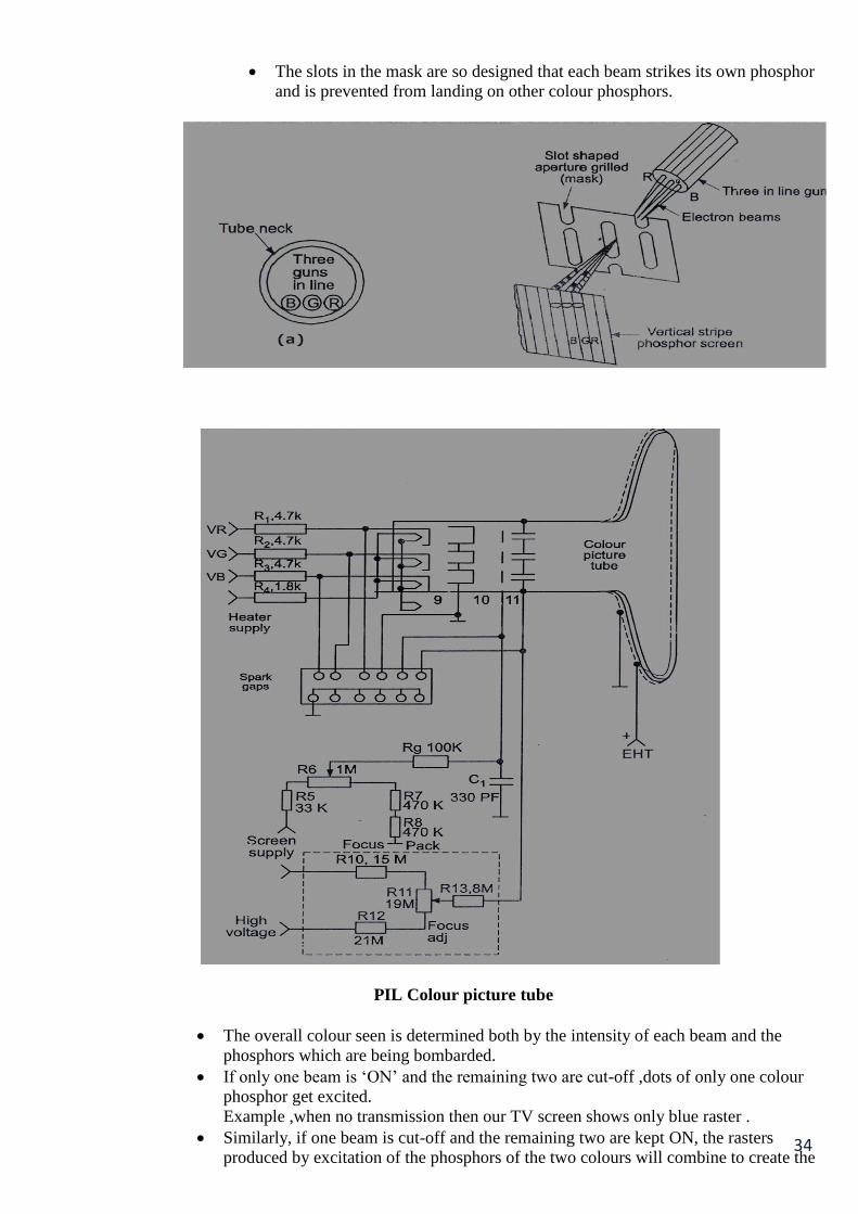
34
The slots in the mask are so designed that each beam strikes its own phosphor
and is prevented from landing on other colour phosphors.
PIL Colour picture tube
The overall colour seen is determined both by the intensity of each beam and the
phosphors which are being bombarded.
If only one beam is ‘ON’ and the remaining two are cut-off ,dots of only one colour
phosphor get excited.
Example ,when no transmission then our TV screen shows only blue raster .
Similarly, if one beam is cut-off and the remaining two are kept ON, the rasters
produced by excitation of the phosphors of the two colours will combine to create the

35
impression of acomplementary colour.
When all the three guns are active simultaneously, lighter shades are produced on the
screen.
This is because red, green and blue combine that forms white and this combines with
Whatever colours are present to desaturate them.
Naturally, intensity of the colour produced depends on the intensity of beam currents.
Back in a picture is just the absence of excitation when all three colour differences
signal to zero ,the only signal left to control the three guns would be Y signal and thus a
black and white picture will be produced.
(c) Why AM is preferred for picture and FM for sound signal transmission?
(2 MARKS FOR EACH) 4 MARKS
AM is preferred for picture because the following reasons,
Because of video's complex nature, AM lends itself to transmitting several different
signals simultaneously, like video, chroma, sync, etc. and it can provide the bandwidth
required to do it easily.
FM is preferred for sound because the following reasons,
FM for the audio has a bandwidth of 100 khz, and FM is much better for that. It's also a
`cleaner signal’. The big advantage of FM is its audio quality and immunity to noise.
d.Draw the block diagram of DTH & explain its operation.
(BLOCK DIAGRAM 2 MARKS,EXPLAINATION 2 MARKS) 4Marks
Ans.
Direct-to-Home(DTH) satellite television is becoming a buzzword in the satellite broadcast
industry due to the fact that DTH offers immense opportunities to both broadcasters and
viewers.
Thanks to the rapid development of digital technology, DTH broadcast operators worldwide
have been able to introduce a large number of new interactive applications in the television
market besides a large number of entertainment programmes over a single delivery platform.
In addition, since digital technology permits a highly efficient exploitation of the frequency
spectrum. The number of TV channels that can be broadcast using digital technology is
significantly higher than with analog technology.
DTH service is the one in which a large number of channels are digitally compressed,
encrypted and beamed from very high power satellites. The programs can be directly
received at homes.
This mode of reception facilitates the use of small receiving dish antennas of 45 to 60 cm
diameter installed at convenient location in individual buildings without needing elaborate
foundation or space etc.
Also, DTH transmission eliminates local cable operator completely since an individual
user is directly connected to the service providers.DTH is contrast to cable TV lends itself
to easy monitoring and control. As mentioned above, all the encoded transmission signals
are digital, thus providing higher resolution picture quality and better audio than traditional
an analog signals. A DTH network consists of broadcasting center satellites, encoders,
multiplexers, modulators and DTH receivers.

36
Diagram:
Block diagram of DTH A DTH service provider has to lease Ku-band transponders from satellite.
The encoder converts the audio, video and data signals into the digital format and the
multiplexers
mixes these signals. At the user end, there will be a small dish antenna and set top box to decode
and view numerous channels.
On the user’s end, receiving dishes can be as small as 45 cm in diameter.DTH is an encrypted
transmission that travels to the consumer at his end through the small dish antenna.
A set top box, unlike the regular cable connection, decodes the encrypted transmission.
e. What is Hi-Fi system? List characteristics of Hi-Fi system.
(DEFINATION OF HI-FI SYSTEM 2 MARKS,CHARACTRISTICS 2 MARKS)
4 MARKS
Ans : * The word ‘fidelity’ means faithfulness. In audio system it is used to indicate faithful
reproduction of sound.
* Hi-Fi system stands for high fidelity stereophonic reproducing system. Such a Hi-Fi
Sound can be obtained from the recorded stereo tape or live systems from the
microphones.
High fidelity reproduction is essentially sound reproduction such that the most critical person
can listen intensity to it without any distortion.
Characteristics of HI-FI amplifier:
1. Signal to noise ratio should be better than 50dB.
2. Frequency response should be flat within +-1dB.
3. Non-linear distortion should not be more than 1%.
4. The system should possess dynamic range of atleast 8dB.
5. Stereophonic effect should be provided.
6. Environmental conditions should be such as to eliminate the external noise in listening
room.
f) What is the need of terminating resistance in MATV? 4 MARKS
Ans.:
Max power is transfer if load impedance is equal to source impedance
If load impedance is not equal to source impedance standing wave pattern is generated.
As terminating resistance in MATV is 75ohm, if source impedance is equal to
terminating impedance, non of the signals are reflected
But if terminating impedance is not equal source impedance signal are reflected back
forming a “GHOST IMAGE” in the TV screen.
The viewer will view a shadow image the picture in his screen.