magnets generate motion
TRANSCRIPT
1Magnets generate motion | Wolfgang David
Magnets generate motionIt is shown as mechanical work may be generated from magnetic forces.
In recent years, an essential characteristic of (permanent) magnet was developed: the forces emanating from them have achieved an unprecedented strength. Thus, a multiple of the usual magnetic field strength can be achieved with the alloy component neodymium (an element of so-called rare earths). As a result, large inductions can be generated in the magnetic circuits.
This way, my experimental spirit was stimulated anew, to deal with the properties of magnetism. By the possibilities of the Internet, it is no problem to the users to learn according to their own abilities and inclinations out of the virtual database. The gentle reader will look up the keywords specified with his favorite search engine. Thus he will receive further information and may even, depending on the skills, keep rising in the depths.
If you are stating the word „magnet motor“ in a search engine, we get a lot of examples and ima-ges of ideas, as a force or rotation could be generated. I am working for some time in this field in order to produce direct movement of magnetic energy and the experiments make me feel confident. This is shown in the following report and in his pictures. The material basis derives from the preliminary developer documentation and was prepared accordingly.
In this sense it is possible to devote a relatively low cost item that may change society and to help it to a new spirit of optimism, namely to create continuous movement out of permanent magnets. That is the magnetic motor. Therefore I have decided to put the results of my attempts to open as early as possible to provide for the general discussion and practical work.
Even if you still want to regard this goal as a vision, the corresponding motivated developer community will present more results soon. But there is still work to do.
In the second half of the 19th century, we in Germany had experienced the enthusiasm with which the development of electrical engineering began. The dynamo-electric principle has then given their importance to the development of the DC machine. Now we are potentially in a time of outcoming inventions with the new magnetic materials. Based on this, I would like to name the principle of direct motion generating „magnetic motor“ or „magnetic-dynamic“.
Westerhorn, March 2015Wolfgang David

2Magnets generate motion | Wolfgang David
1. Reflections on the iron as a magnetic material
If we imagine that a piece of iron is already assembled in its crystal structure of elementary ma-gnets, so it follows that the magnetic properties of the material are yet in place, but not always outwardly appear. The rationale is believed that depending on the order in the crystal structure, the magnetic forces are outwardly noticeable, which are known as attraction and repulsion. Dis-order in the elementary magnets give the contrary, that is the non-magnetic behavior. Magnetic behavior is bound to the subtle order and means that the elementary magnets to show more or less in the same direction (depending on the exciting field strength). The field lines start out from the North Pole and go in the South Pole. They have no beginning and no end, so they are closed polylines.
Electrical machines make ample use of the magnetic forces in the performance of work. The machines were usually constructed in two parts and consist of a stator with a rotating part in the middle, the rotor. An air gap between the two is necessary so that any mutual rotation is possible. This principle arising from the early days of electrical machines has not really changed until today. The magnetic resistance of the air gap requires almost the entire excitation power, whereas the magnetic excitation in the other machine parts is almost negligible. This also means that you want to keep the air gap of a machine as small as possible.
Electromagnetism is easily be influenced because it depends directly on the effective dc-current. No current means no magnetism (in an air coil). The reversed current direction results in a re-versal of the magnetic field. Large current results in a strong excitation (= strong magnetic field). Low current results in a weak magnetic field.
The rotor of a DC motor bears the windings, while the ends of them are fixed to copper plates (collector). The current supplied to the magnetize the rotor (in a particular direction) begins a rotational movement in interaction with the magnetic field of the stator (housing). But this would come at least to an end after half a revolution because the cooperating magnetic fields (rotor and stator) do not give any more resultant torque. The invention is that the rotor current is supplied via sliding brushes. Moving the rotor further moves also the collector so a new pair of sliding contacts come in action. While the brush interaction takes over the current supply, it is switching to a new solenoid. So the rotation is maintained, and the engine is running.
Magnetism Neodymium hysteresis loop
elementary magnets permanent magnet magnetic field strength
Bloch walls attraction unipolar machine
Magnetic induction repulsion
3Magnets generate motion | Wolfgang David
2. Permanent Magnets
Today‘s materials, which are used for the construction of permanent magnets have a high co-ercivity and can generate very high inductions in the ferromagnetic circuit. As in the physical theory the current is the cause of a magnetic field, it can be said conversely that permanent ma-gnet inner atomic currents are effective. That inner field strength inside of a permanent magnet has a high coercivity and can generate very high inductions in the ferromagnetic circuit. This is always present, therefore, the term „permanent“-Magnet. Magnets exert a force action on their environment, if it exists of magnetizable material. It attracts magnetizable material (eg. iron).
The current effect of a permanent magnet can be thought of as „superconductivity at room temperature“, a free treasure of nature: no copper winding, no excitation current, no cryogenic cooling, no flashlight battery. Just sits there and works.
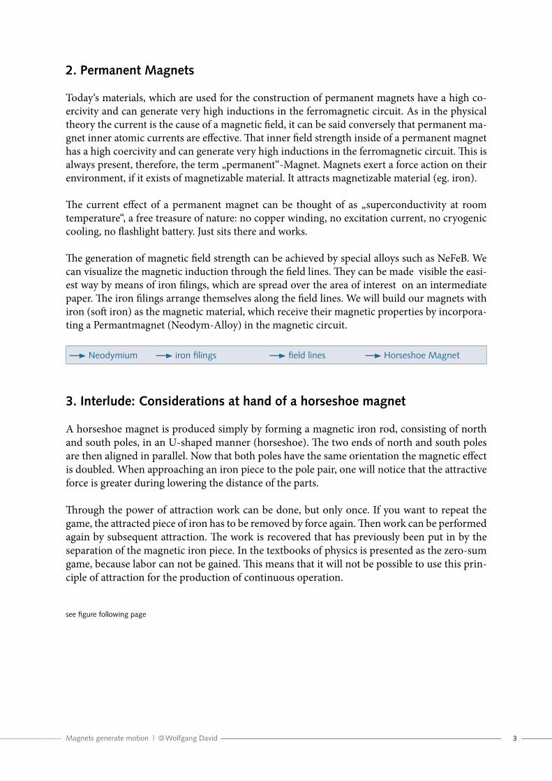
The generation of magnetic field strength can be achieved by special alloys such as NeFeB. We can visualize the magnetic induction through the field lines. They can be made visible the easi-est way by means of iron filings, which are spread over the area of interest on an intermediate paper. The iron filings arrange themselves along the field lines. We will build our magnets with iron (soft iron) as the magnetic material, which receive their magnetic properties by incorpora-ting a Permantmagnet (Neodym-Alloy) in the magnetic circuit.
Neodymium iron filings field lines Horseshoe Magnet
3. Interlude: Considerations at hand of a horseshoe magnet
A horseshoe magnet is produced simply by forming a magnetic iron rod, consisting of north and south poles, in an U-shaped manner (horseshoe). The two ends of north and south poles are then aligned in parallel. Now that both poles have the same orientation the magnetic effect is doubled. When approaching an iron piece to the pole pair, one will notice that the attractive force is greater during lowering the distance of the parts.
Through the power of attraction work can be done, but only once. If you want to repeat the game, the attracted piece of iron has to be removed by force again. Then work can be performed again by subsequent attraction. The work is recovered that has previously been put in by the separation of the magnetic iron piece. In the textbooks of physics is presented as the zero-sum game, because labor can not be gained. This means that it will not be possible to use this prin-ciple of attraction for the production of continuous operation.
see figure following page

4Magnets generate motion | Wolfgang David
4. Influence of a shunt at the horseshoe magnet
If a horseshoe magnet is provided with a shunt between its legs, it is immediately apparent that a portion of the magnetic induction is shorted. So you will observe a lower power development than without. The attraction of a piece of iron will be less as described in the preceding section.
The shunt (whether present or not) puts us in a position to influence the strength of the mag-netic field. No shunt results in the maximum force acting on the magnetic poles (outside edges) whereas the introduction of a shunt has a decreased force action.
The utilization of both arrangements should make it possible to build a machine that receives its force action from the magnetic field itself. Of crucial importance, of course, is the property of the iron, which in its subtle behavior is suited for a construction of a machine. Depending on the exciting field, strength raises the size of the magnetic induction by itself (hysteresis loop). Various inductions are necessary in order to achieve a differential effect between two positions, which then finds its balance in the movement.
(field lines not complete in this representation)
horseshoe magnet and iron cuboid
attraction force
N
S
perspective representation cuboid
north pole south pole
field lines
less attraction force due to bypass
N
S
bypass (iron)
5Magnets generate motion | Wolfgang David
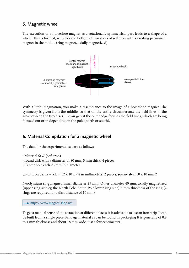
5. Magnetic wheel
The execution of a horseshoe magnet as a rotationally symmetrical part leads to a shape of a wheel. This is formed, with top and bottom of two slices of soft iron with a exciting permanent magnet in the middle (ring magnet, axially magnetized).
With a little imagination, you make a resemblance to the image of a horseshoe magnet. The symmetry is given from the middle, so that on the entire circumference the field lines in the area between the two discs. The air gap at the outer edge focuses the field lines, which are being focused out or in depending on the pole (north or south).
6. Material Compilation for a magnetic wheel
The data for the experimental set are as follows:
• Material St37 (soft iron)• round disk with a diameter of 80 mm, 5 mm thick, 4 pieces• Center hole each 25 mm in diameter
Shunt iron ca. l x w x h = 12 x 10 x 9,8 in millimeters, 2 pieces, square steel 10 x 10 mm 2
Neodymium ring magnet, inner diameter 25 mm, Outer diameter 40 mm, axially magnetized (upper ring side eg the North Pole, South Pole lower ring side) 5 mm thickness of the ring (2 rings are required for a disk distance of 10 mm)
https://www.magnet-shop.net
To get a manual sense of the attraction at different places, it is advisable to use an iron strip. It can be built from a single piece Bandage material as can be found in packaging It is generally of 0.8 to 1 mm thickness and about 18 mm wide, just a few centimeters.
„horseshoe magnet“ rotationally symmetric
(magenta)
center magnet (permanent magnet,
light blue) cent
er h
ole
magnet wheels
example field lines (blue)

6Magnets generate motion | Wolfgang David
The thickness of the permanent magnet portion is 10 mm, made of 2 rings. Thus it is quite pos-sible to bring in the shunt iron from a slightly lower thickness (eg 9,8 mm) with a pair of pliers. The shunt iron is then set between the panes of then magnetic wheel.
Try out the better solution if any, there may be other dimensions (experiment!). The above di-mensions will give a good indication for the experiment. It is important that the shunt iron get enough space and some free space on both sides (radially inward or outward).
Trying the experiment with smaller permanent magnets (ring magnet of 12 / 4 mm diameter, 6mm high) was also done. As iron pieces large washers were provided. These however, had not enough thickness and were also worked inaccurate. So.they were not be able to take all the inductance and have gone instead uncontrollably into saturation. Hence the effect of the field weakening has not worked sufficiently. Generally speaking one can state that the possibilities of ordinary home workshop is not sufficient to make further experiments.
7. Two magnetic wheels working together
The rolling of two magnetic wheels is shown below:
The magnetic wheels have the field lines from the middle (inside) radially expanded into their surfaces of the wheel pane. They also have the magnetic forces spread in outside direction as can be seen in the horseshoe magnet in unidirectional viewing.
The assembly of two magnetic wheels is very easy, since they are self attracting (if necessary turn one side by 180 degrees). The expected attraction is considerable. It rolls both wheels on each other, so that the bearing forces on both axles are actually still low. Now you can see what was meant about when we told from a machine with the zero air gap. The center axes of the two magnetic wheels stand apart in distance of 80mm. The tolerance of the diameter may vary in slightly different values, but this is not really important for the experiment. The important thing is the equality of the diameter of the wheels. Thus it is prevented that a jam occurs and friction stops the entire motion.
contact by attraction
S
N
cent
er h
ole
S
N
S
NN
S
axle and direction of rotation
N
S
cent
er h
ole
N
S S
N
S
N

7Magnets generate motion | Wolfgang David
It may be possible that the experiments require an air gap between the two iron wheels. This can be easily accomplished without affecting the direct rolling: applying a non-magnetic coating on the outer circumference. A test, for example, is impementing a gold-plate surface, which is easy to apply (handicraft shop). The air gap of course is invisible, but still magnetically active. The effective air gap length can be controlled well by the thickness of the plating.
8. Roll-off problems and Hertz pressure
The material of the magnetic wheel is made of iron. The wheels runs from iron to iron. Since the amount of attraction may cause break-outs in the material, the smoothness of the running sur-faces may be disturbed until beeing impossibly. This phenomenon is comparable with the barrel of a roller skate on a base with split, where under certain circumstances no longer roll movement will be possible. It is therefore a special attention be paid to the rolling of the two magnet wheels to prevent excessive magnetic forces that surface pressures (pitting) comes up. By the withdra-wal of the field strength in the magnetic excitation, a reduction of attractiveness can be achieved. A magnetic ring to be replaced by an iron ring of the same dimensions will lead then to half the excitation. On the other hand, one could increase the thickness of the iron discs of the magnet wheels to get to a lower induction. This is now a wide field for experimentation.
Hertz(ian) pressure
9. Sinusoidal running of the two magnet wheels (wave travel)
In the combination of wheels and rails you look at rail vehicles, involuntarily comes to the idea that similar conditions prevail even when the magnet wheels. So it is important to provide the wheels with similar profiles as they exist at the wheel-rail system: a magnetic wheel corresponds to the track profile during the second magnetic wheel with a conical profile rolls across it. The tracking (sinusoidal running) is then given by itself. Of course, no flange is needed as in the Rail-way since the two magnetic wheels have sufficient guidance and avoids touching the side panels. It is also conceivable to make the suspension that way, so that a magnetic wheel (the inside) has the guide (rail), whereas the other (outer) wheel rolls above on it. The outer wheel then needs only a single and central (groove-) ball bearing for tracking, while the clearance is sufficient enough to bring the optimal self-adjustment of the rolling pair.
Sinusoidal run wave travel

8Magnets generate motion | Wolfgang David
10. General explanation on handling with magnets
Several years ago it was unthinkable to get as strong magnets, as is now possible today. Likewise, they are also affordable and therefore available to the general user community in various versi-ons. The Internet companies ships them quickly and safely.
But be careful! When you unpack the package, you have to see that you have built up enough space around yourselves. It will be promptly recognized that the anticipated attractions of the parts have been underestimated and you will find all the pieces as a bulk adhered, with a cla-cking over the distance of centimeters. This reminds of a garden pond, where you can only enumerate the splashes, of how many frogs have been submerged. This is the test number 0. The second time you will give a little more space and still wonder that even a large sofa is usually still too small.
The attractions will be often underestimated by the magnet to magnet or magnetic iron. They are given for example in the catalogs. Depending on the measurement method you will get a value of e.g. „attraction 8kp =“ (This is the ring magnet from the experiment described). This is a very strong attraction, especially when the thumb gets in between. At least very painful skin injuries are very likely. Annoyingly, the holding force is the greater, the more you have to move out the fingers of the pinch, because the magnetic forces increase with a smaller distance. It is advisable to wear a pair of gloves during handling magnets. Thus it will be provided for the most injuries at least. Swallowing (neodymium) magnet can be life-threatening. Because if two magnets get tighthen in the stomage, it may be that parts of the intestine become trapped. That is the maximum imaginable accident which simply must not happen. In other words, children have not to play around in the place of work as long as there is a risk, that they can steal unattended magnetic material and hence swallowed.
The dealer put their Instruction to handle their magnetic material into the consignment, in or-der to inform the customer about the potential dangers. These must be observed!

9Magnets generate motion | Wolfgang David
11. The rotating machine as an experiment
The interactive rolling wheel discs have really no reason to cause a movement. The reason is that in this arrangement, the complete symmetry of the individual components prevail. Thus it can not come to a decision between right or left. Only through the impairment of symmetry a com-pensating movement occurs. For this purpose it is necessary to introduce a shunt.
By connecting both centers of the wheel discs with a thought straight line, we get the point of contact of the two wheels in the middle. Above the connecting straight line is the area of the reduced induction, because there the shunt parts have been introduced. In the experiment, the shunt parts are inserted directly between the two wheel discs and stick there very firmly. They move with the wheels. That should be enough for the static attempt. The area below the connec-ting line is acted upon by the full induction as resulting from the magnet in the midpoint. We have close to the contact point (down to up), a difference of induction which makes it possible that both wheels roll on each other and swing from the middle towards the top direction.. The left wheel turns around counter-clockwise, with the right wheel join in the counter-movement. This move comes to an end after a quarter turn, because the revolving shunt parts are moved concurrently out of their working range.
Eddy currents Lenz‘s Law
Topview of bypass
imagined neutral line
magnetic wheels (movable)
high density of field lines
low density of field lines
cent
er h
ole
cent
er h
ole
10Magnets generate motion | Wolfgang David
For the current experiment, which will be called the static one because of its small size, the use of the clamped and revolving shunt parts should be enough. These then produce about a quarter turn which necessarily comes to a standstill. It is possible to make this test with very little effort on storage technology: a wooden board as a backing is sufficient to detect the effect of the rota-tion. On turning back the wheel discs to the starting position, the game can begin a new.
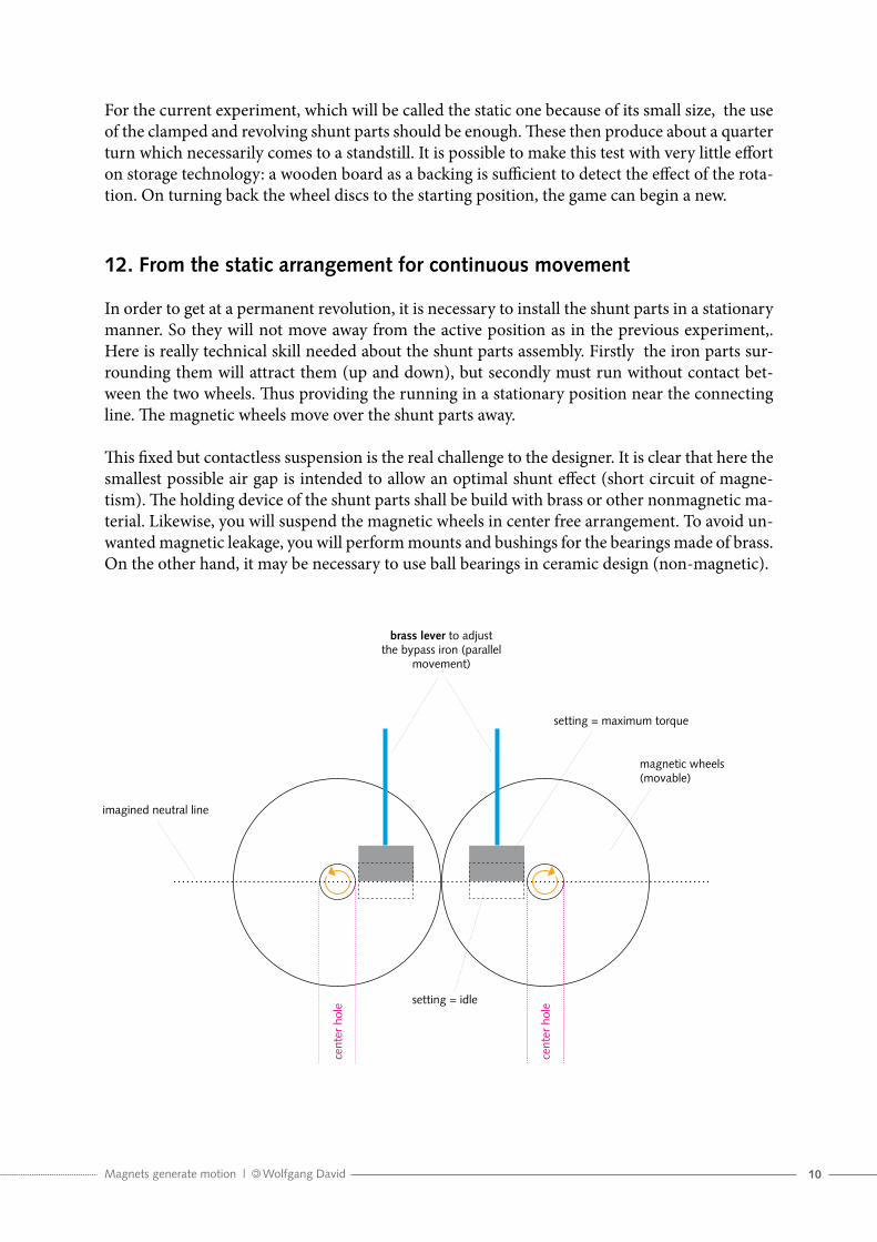
12. From the static arrangement for continuous movement
In order to get at a permanent revolution, it is necessary to install the shunt parts in a stationary manner. So they will not move away from the active position as in the previous experiment,. Here is really technical skill needed about the shunt parts assembly. Firstly the iron parts sur-rounding them will attract them (up and down), but secondly must run without contact bet-ween the two wheels. Thus providing the running in a stationary position near the connecting line. The magnetic wheels move over the shunt parts away.
This fixed but contactless suspension is the real challenge to the designer. It is clear that here the smallest possible air gap is intended to allow an optimal shunt effect (short circuit of magne-tism). The holding device of the shunt parts shall be build with brass or other nonmagnetic ma-terial. Likewise, you will suspend the magnetic wheels in center free arrangement. To avoid un-wanted magnetic leakage, you will perform mounts and bushings for the bearings made of brass. On the other hand, it may be necessary to use ball bearings in ceramic design (non-magnetic).
magnetic wheels(movable)
setting = maximum torque
setting = idle
brass lever to adjust the bypass iron (parallel
movement)
imagined neutral line
cent
er h
ole
cent
er h
ole
11Magnets generate motion | Wolfgang David
13. Control of the rotational movement (forward / reverse operation, torque)
The introduction of the shunt between a magnetic wheel makes it possible to vary the torque generated depending on the position with respect to the connecting line.
When the shunt exactly (and balanced) is on the line of the connecting line between the two magnetic wheels, we also have no usable resulting difference of induction.
This can be regarded as zero position between the rotation. The direction of rotation of the two discs will be adjusted depending on the deflection of the shunt. (At this point it would be possib-le to introduce a centrifugal governor on the type of the first steam engines to prevent a runaway of the machine.) If the magnetic shunt position is adjusted more towards zeroing (also called idle or center), the less driving force (torque) is felt remaining.
It is of course possible to use not only one magnetic wheel pair. So you can obtain a bigger torque with several outside wheels Note, since the effect of the difference will also increase with the number of wheels.
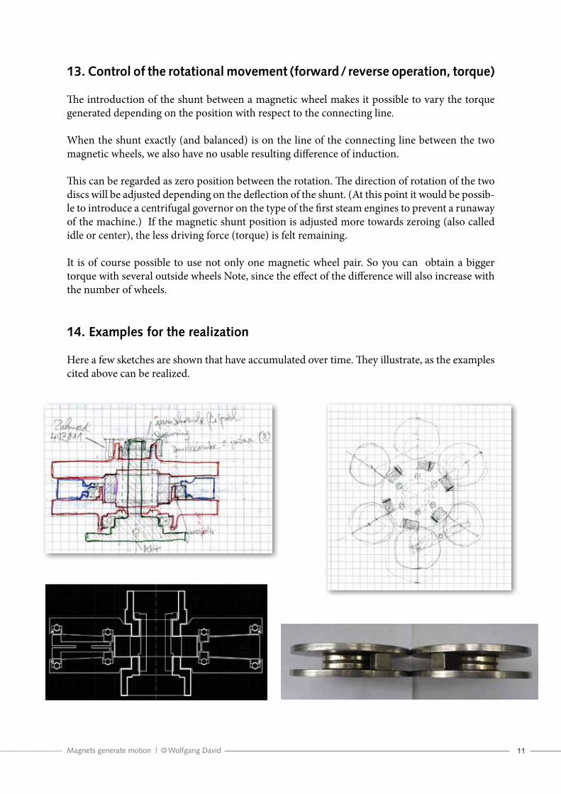
14. Examples for the realization
Here a few sketches are shown that have accumulated over time. They illustrate, as the examples cited above can be realized.
12Magnets generate motion | Wolfgang David
Epilogue
If you, dear reader have me followed so far, you may have got an idea of the underlying prin-ciples „movement by magnets“. Perhaps the desire arose in you to experiment by yourself and contribute to the success of this idea. I deliberately set out that in the first place is the joy of experimentation in the foreground. We can calculate on this matter later. Because there are still many hurdles to overcome.
And I wish you every success!