magnetic resonance imaging assisted by wireless passive
TRANSCRIPT

Received July 7, 2017, accepted August 24, 2017, date of publication September 14, 2017, date of current version October 12, 2017.
Digital Object Identifier 10.1109/ACCESS.2017.2752649
Magnetic Resonance Imaging Assisted byWireless Passive Implantable Fiducial e-MarkersSAYIM GOKYAR1, (Student Member, IEEE), AKBAR ALIPOUR1, (Student Member, IEEE),EMRE UNAL1, ERGIN ATALAR1, (Senior Member, IEEE),AND HILMI VOLKAN DEMIR1,2, (Senior Member, IEEE)1National Magnetic Resonance Research Center (UMRAM), Department of Electrical and Electronics Engineering, UNAM-Institute of Material Science andNanotechnology, Bilkent University, Ankara TR-06800, Turkey2Luminous! Center of Excellence for Semiconductor Lighting and Displays, School of Electrical and Electronic Engineering, School of Physical andMathematical Sciences, Physics, Nanyang Technological University, Singapore
Corresponding author: Sayim Gokyar ([email protected])
This work was supported by UNAM, TÜBA and TUBITAK-BIDEB.
ABSTRACT This paper reports a wireless passive resonator architecture that is used as a fiducial electronicmarker (e-marker) intended for internal marking purposes in magnetic resonance imaging (MRI). As a proof-of-concept demonstration, a class of double-layer, sub-cm helical resonators were microfabricated and tunedto the operating frequency of 123 MHz for a three T MRI system. Effects of various geometrical parameterson the resonance frequency of the e-marker were studied, and the resulting specific absorption rate (SAR)increase was analyzed using a full-wave microwave solver. The B+1 field distribution was calculated, andexperimental results were compared. As an exemplary application to locate subdural electrodes, thesemarkers were paired with subdural electrodes. It was shown that such sub-cm self-resonant e-markerswith biocompatible constituents can be designed and used for implant marking, with sub-mm positioningaccuracy, inMRI. In this application, a free-space quality factor (Q-factor) of approximately 50 was achievedfor the proposed resonator architecture. However, this structure caused an SAR increase in certain cases,which limits its usage for in vivo imaging practices. The findings indicate that these implantable resonatorshold great promise for wireless fiducial e-marking in MRI as an alternative to multimodal imaging.
INDEX TERMS Magnetic resonance imaging, wireless resonators, fiducial e-markers, implants.
I. INTRODUCTIONMagnetic resonance imaging (MRI) has been attract-ing increasing interest for the localization of implantabledevices (e.g. subdural electrodes). Although the soft tissuecontrast of MRI [1] makes it the strongest tool among otherimaging modalities (including X-ray, CT, and PET), the posi-tioning of devices underMRI requires special treatment, suchas employing wired connections [2]–[4] and [5], introduc-ing MRI marker materials [6]–[10] and [11] using wirelesspassive devices with inductive coupling [12], [13].
Using wired connections to electrically reach implanteddevices under MRI is limited to interventional applica-tions [14] and comes at the cost of increased radiofre-quency (RF) heating risk [15]. Using 1H-containing MRIvisible marker materials such as bearings [6], [7],vitamin-E capsules [8] and dyes [9], [10], has other disad-vantages, including physical attachment to the imaged object,size and non-adjustable relaxation parameters. Thesemarkers
typically have sizes of several mm in three dimensions,which limits their in vivo usage for most clinical applications,such as subdural electrode marking. Additionally, once theyare manufactured, the longitudinal (T1) and transverse (T2)relaxation times of these markers will be constant, and theirvisibility will strictly depend on the MRI parameters, includ-ing repetition time (TR) and echo time (TE). This may limitthe imaging methods; hence, additional scans with proper TRand TE values should be performed for marking of fiducialdevices. Simultaneous imaging of marking materials andanatomical features is critical to achieve better registrationaccuracy [16].
In addition to these methods, multimodal imaging isalso used to mark the locations of the subdural elec-trodes [17]–[20]. However, the registration of images thatare acquired from different platforms results in reliabilityproblems due to larger positioning errors typically rangingfrom 1 to approximately 3 mm [21], [22]. In addition to the
VOLUME 5, 2017 This work is licensed under a Creative Commons Attribution 3.0 License. For more information, see http://creativecommons.org/licenses/by/3.0/ 19693

S. Gokyar et al.: MRI Assisted by Wireless Passive Implantable Fiducial e-Markers
reliability problems, switching the patient from one platformto another also decreases the patient’s comfort and increasesthe risk of inflammation. The ability to image implantabledevices using only MRI will avoid the need for multimodalimaging platforms, which will result in improved clinicalpractice.
The use of wireless resonant devices is potentiallyhighly promising for marking implantable devices withoutrequiring multimodal imaging. MRI performance of thesewireless markers is loosely dependent on the imaging param-eters (TR, TE and resolution). However, the use of e-markersrequires novel resonator designs for proper operation.Physical dimensions of these markers together with RFsafety concerns should be considered for the surroundingtissues [15]. Decreasing RF power is a good practice to pre-vent patients from the harmful effects of RF exposure, but thisundesirably leads to a lowered signal-to-noise-ratio (SNR) onthe acquired MRIs and decreases the reliability of images fordiagnoses, especially for regions with lower proton densities.
In this work, we designed and demonstrated an innova-tive structure that alleviates the potential complications ofthe previous works in the literature and can be used as awireless MRI marking device for potential in vivo studies,such as marking subdural electrodes. Here, we address thescientific challenge of achieving a low footprint area andhigh Q-factor simultaneously for a 123 MHz self-resonancefrequency. As a proof-of-concept demonstration, we achievedan 8 mm× 8 mm footprint area with a free-space Q-factor ofapproximately 50 for the given operational frequency. Here,we also report the simulation results of the specific absorptionrate (SAR) increase in the brain. Ex-vivo MR images supportthat the proposed architecture is an excellent candidate forwireless electronic markers (e-markers). This may create newpossibilities for next-generation implants that contain inte-grated wireless e-markers.
FIGURE 1. Schematic layout of the proposed design (not drawn to scale).
II. THEORYThe proposed e-marker architecture, illustrated in Fig. 1, is athin film loaded double-layer helical structure that can befabricated in its multilayer form or in the form of incom-plete turns. Instead of stacking independent split-ring res-onators (SRR) among different layers [23], this structurecombines them with a proper via metallization to increasethe effective inductance (Leff ), and thus further decreases
the resonance frequency to compensate for MRI applicationswithout compromising the footprint area.
For electrically very small systems, the circuit theoryapproach becomes reasonable to model the basic character-istic parameters. Hence, the Q-factor of the resonator shownin Fig. 1 can be expressed as:
Q =w0LeffReff
(1)
where w0 is the angular frequency, Leff is the effective induc-tance and Reff is the effective resistance of the resonator.
The most important component of this device is the via-metallization that connects the opposite sides of the resonatorbetween different layers, allowing for strong inductive cou-pling. As deduced from [24], the approximate effective induc-tance and resistance of the given design can be formulated as:
Leff = n2L0 (2)
Reff = nR0 (3)
where L0 is the inductance of a single layer, n is the numberof turns, and R0 is the resistance of a single turn. By substi-tuting (Eqn. 2 and 3) into (Eqn. 1), we obtain:
Q =w0n2L0nR0
= nw0L0R0= nQ0 (4)
concluding that the Q-factor is increasing with the number ofturns for this special structure at a constant pre-determinedoperating frequency [25]. Increasing the number of turns forconventional structures (e.g., spirals, solenoids and SRRs)will not linearly increase the quality factor due to loweredinductance for the consecutive turns [26]. Hence, this geome-try is very special in terms of the high quality factor and built-in capacitance to be tuned to pre-determined MRI frequency.
The effective parallel plate capacitance (Ceff ) createdbetween consecutive layers is also used to tune the oper-ational frequency of this geometry to a pre-defined MRIfrequency and avoids the need for the use of external capac-itors, enabling ultra-thin and flexible structures. With thisdesign, it is possible to create very large capacitance valuesusing conventional fabrication methods to tune this structureto a broad range of frequencies to be used for differentapplications.
III. MATERIALS AND METHODSUnlike wired antenna systems used in MRI, this wireless res-onator does not require complicated electronics to match anyinput impedance level. This removes the burden of matchingcapacitors, resulting in more compact solutions with loweredartifacts. Tuning the resonance frequency of a wireless res-onator to a pre-defined MRI frequency becomes challengingwhen there is no space for the lumped elements (e.g. capaci-tors and inductors). Regarding the engineering design, as wellas geometric parameters, it is important to simultaneouslyachieve a low footprint area, decreased resonance frequencyand higher quality factor.
19694 VOLUME 5, 2017

S. Gokyar et al.: MRI Assisted by Wireless Passive Implantable Fiducial e-Markers
FIGURE 2. Simulation environment to obtain RF characterization of theproposed design.
A. NUMERICAL SIMULATION ENVIRONMENTTo understand the effect of different design parame-ters on the resonance frequency, we used CST-DesignStudioTM (Computer Simulation Technologies, Darmstadt,Germany). Fig. 2 depicts the simulation environment for theproposed structure with two ports located in the z-directionthat are consecutively labeled 1 and 2.
Scattering parameters (S11 and S21) were obtained, withboundary conditions of the perfect-electrical-conductor (PEC),perfect-magnetic-conductor (PMC) and perfectly matchedlayer in the x, y and z directions, respectively. The simulationenvironment was extended with the side length of the res-onator (e.g., 8 mm in this case) in all directions. Polyimidematerial from the library of the numerical solver was usedas the dielectric layer with a variable thickness (tdielectric),and gold (Au) was used as the metal layer with a variablemetallization width (w). Both tdielectric and wwere swept overa range of values to understand their effect on the resonancefrequency of the resonator.
To verify the superiority of the present architecture,we simulated a 3-D body model from the library of the CSTMicrowave StudioTM, using a birdcage coil with a diameterof 70 cm and a length of 120 cm tuned to 123 MHz. It haspreviously been shown that the tissue parameters (hence, RFcharacteristics) of adults and children [27] and [28] and theperformance levels of different solvers [29] are not consid-erably different from each other. Thus, we used a child’sbody model to decrease the computational burden as a resultof the reduced tissue volume. Numerical SAR results wereacquired using a time domain solver and a power lossmonitor.Time-averaged SAR values were calculated by using thetime derivative of the incremental energy (absorbed by anincremental mass of 1 and 10 g of tissues).
B. MRI EXPERIMENT SETUPMRI measurements were taken using a 3 T SiemensTim Trio System (Siemens Healthcare GmbH, Erlangen,Germany)with a body-mimicking liquid phantom composedof 2 mM copper sulfide solution (CuSO4.5H2O, with 98%purity of Merck) and 50 mM of NaCl, which mimicsmost tissues [30], with a relative permittivity of approxi-mately 60, conductivity of 0.5 S/m [31], T1 of 114 ms andT2 of 82 ms. The characteristic parameters of this phantomare suitable to analyze the in vivo loading performance of
the resonator. Here, initial images were acquired by usingthe body coil as the transmitter and the standard twelve-channel head coil as the receiver using a spoiled gradient echosequence (also known as gradient-recalled echo, GrE), with a100 mm × 100 mm field of view (FOV) in the trans-verse plane, 256 × 256 image resolution, 2 mm slice thick-ness, TR/TE of 100 ms/10 ms, 260 Hz pixel bandwidth,a flip angle of 10◦ and total imaging duration of 29 s.To extract the experimental B+1 map for the double-anglemethod [32], we used two saturated GrE images with flipangles of 10◦ and 20◦.
FIGURE 3. An eight-channel open surface coil system used for ex-vivoanimal studies.
As a proof-of-concept demonstration, we prepared animaging environment with an eight-channel open surface coilarray, dedicated to animal experiments, and a rabbit usedfor ex-vivo imaging was placed in the scanner as shown inFig. 3. Necessary steps were taken to follow the nationallaws (5199, February, 2014), ruled by the European UnionDirective 2010/63/EU, for animal experiments. The rabbitwas positioned on the patient bed of the scanner and trans-verse images were acquired for marking purposes. Imageswere acquired by using the body coil as the transmitterand the surface coil as the receiver with GrE sequence,100 mm × 100 mm FOV in the transverse plane,256 × 256 image resolution, 2 mm slice thickness, TR/TEof 100 ms/10 ms, 260 Hz pixel bandwidth, a flip angle of 3◦
and total imaging duration of 29 s.Marking precision of themarker-electrode pair was studied
by using methods provided in the literature [33]. One oftwo pairs of electrodes was stabilized to the iso-center of apolycarbonate container and used as the reference point forMRI positioning; the second electrode pair was translatedalong the imaging plane (coronal) by using the grid pointsof the phantom-filled container. We used a GrE sequence(TR= 100 ms, TE= 10 ms, flip angle= 10◦, slice thickness= 3 mm, FOV= 220 mm× 220 mm) to acquire the positionof the translated marker-pair, which was compared to thereference by using 2D Gaussian fit. The actual position wasmeasured by using a ruler and the estimated position wasobtained from the MR images for different resolutions. Theerrors between the actual and estimated positions of the pairswere calculated in two dimensions. Euclidian distance wasobtained from these two orthogonal directions to acquire theresulting marking accuracy.
VOLUME 5, 2017 19695

S. Gokyar et al.: MRI Assisted by Wireless Passive Implantable Fiducial e-Markers
FIGURE 4. Resonance frequency characteristics of the proposed design:(A) due to dielectric thickness and (B) due to metallization width.
IV. RESULTS AND DISCUSSIONA. FREQUENCY TUNINGFor the constant footprint area (8mm× 8mm for this applica-tion), it is possible to change the parametersw, tdiel , metalliza-tion thickness (tmetal), gapwidth (g) and comb sizes (a1 or a2).It is obvious that the thin-film capacitance mainly dependson w and tdielectric, while the other parameters affect thequality factor (e.g., tmetal) and field confinement volume(e.g. g and a1). Here, we swept values of tdielectric from 1 to10 µm and w from 0.5 to 2.5 mm with the abovementionedsimulation domain parameters to acquire the resonance fre-quencies.
Fig. 4A shows the results of the various dielectric thick-nesses for a fixed w (0.5 mm). The thin-film capacitanceis inversely proportional to the dielectric thickness. Thus,thinner dielectrics confine higher electric field intensities toachieve higher thin-film capacitance, resulting in loweredresonance frequency. With this dielectric thickness range,it is possible to cover the 1.5 T (e.g., 64 MHz) and 3.0 T(e.g., 128 MHz) MRI frequencies.
Fig. 4B shows the resonance frequency as a function of wfor a fixed dielectric thickness (tdiel = 7.5 µm). The effect ofw on the resonance frequency is more complicated than thatof tdielectric. Increasing w increases the parallel plate surfacearea, resulting in increased thin-film capacitance. However,it also lowers the effective inductance [24] and the quality fac-tor (see Eqn. 5) of the overall structure. Since the resonancefrequency is inversely proportional to the multiplication ofeffective inductance and capacitance, it will reach aminimumdue to the maximum of this product. Hence, it is important tobe careful when adjusting metallization width to decrease theresonance frequency.
FIGURE 5. Resonance frequency characteristics of the tuned structure fora = 8 mm, w = 1 mm, tdielectric = 7.5 µm, tmetal = 10 µm, g = 1 mm,a1 = 4.5 mm and a2 = 2.5 mm.
For our case, the optimalw/a ratio is approximately 0.12 inwhich the resonance frequency drops to its minimum. Forour experimental use, we set the w/a ratio as 0.125 (e.g.,w = 1 mm for a = 8 mm) with a higher inductancevalue to keep the quality factor reasonably high. To final-ize our design, we selected w = 1 mm, a = 8 mm,a1 = 4.5 mm, a2 = 2.5 mm, g = 1 mm, tdielectric =7.5 µm (due to the thickness of Kapton HN-30) and tmetal =10 µm (due to the skin depth of EM waves at 123 MHz).Fig. 5 shows the numerical results for the scattering parame-ters of the proposed architecture with the above dimensionsand simulation environment. The tuned structure’s resonancefrequency was approximately 122 MHz with a strong reso-nance behavior.
B. MICROFABRICATION AND RF CHARACTERIZATIONWe microfabricated a resonator onto an 8 mm × 8 mm foot-print area by using a Kapton R© (HN 30, Dupont ,Wilmington,Delaware, USA) polyimide film with a thickness of 7.5 µmas the dielectric layer sandwiched between the metal lines.Before starting the metallization process, we cleaned thesubstrate with oxygen plasma. By using a hard-mask withasymmetric comb sizes (a1 = 4.5 mm, g = 1 mm anda2 = 2.5 mm), we thermally evaporated two 10 µm thickTi/Au metals, on opposite sides of the Kapton R©film, andadditionally introduced a cross-connection via metallization
19696 VOLUME 5, 2017

S. Gokyar et al.: MRI Assisted by Wireless Passive Implantable Fiducial e-Markers
FIGURE 6. Microfabricated device: (A) Optical image of the devicefabricated onto flexible polyimide and (B) RF characterization of the samedevice for resonance frequency determination.
through a gap in the substrate, joining opposing pairs of edgesfrom the metallization layers on the two sides. Then, a 20µmthick Polydimethylsiloxane (PDMS) layer was coated on bothsides for electrical isolation of the conductive layers from thetissues. A microfabricated device is presented in Fig. 6A.
Experimental RF characterization of the microfabricatedresonators was carried out by using standard methods pro-vided in the literature [34]. Input impedance of the pick-up coil, which has the same footprint area as the marker,was measured with a network analyzer (Agilent E5061B,Agilent, Santa Clara, California, USA). In the impedancegraph presented in Fig. 6B, which was extracted from theinput impedance of the pick-up coil, we find the reso-nance frequency of the fabricated e-marker to be 125.3 MHzwith a corresponding free-space wavelength (λ0) of 2.39 m.By using the full-width-half-maximum (FWHM) of theimpedance graphs in Fig. 6B, we calculated a quality
factor of approximately 50 for this resonance frequency.Similarly, a resonator-electrode pair was measured with thesame method resulting in a loaded Q-factor of 42 that meansa small decrease in the Q-factor, which is in agreementwith previous results [35]. We found that the side lengthof the resonator (8 mm) was approximately λ0/300, whichis one of the smallest single-chip deep-subwavelength res-onators described in the literature that does not use a lumpedelement [26].
Resonance frequency estimation by using numerical meth-ods deviated only 3 MHz from the measurement results,which might be due to dielectric coefficient differences ofthe material available in the library. Another possible reasonfor this deviation is the misalignment of consecutive layers,which decreases effective capacitance. Hence, this resultsin an increased resonance frequency for the experimentalcase. These results are in good agreement with each other,indicating that the MRI frequencies for most of the clinicalsystems (1.5 and 3 T) are easily achievable.
Reaching lower resonance frequencies is feasible for thisarchitecture, and tuning to higher frequencies can be accom-plished by simply partially etching one of the metalliza-tion layers. We would deduce that resonance frequenciesfrom 70 MHz to 5.5 GHz are possible by simply using thesame structure, as the self-resonance frequency increases to5.5 GHz for a single-layer loop resonator with these dimen-sions. The superiority of the given architecture, specificallyachieving ultra-wide-band tuning performance, allows it to beused as a fiducial marker for awide range ofMRI frequencies.
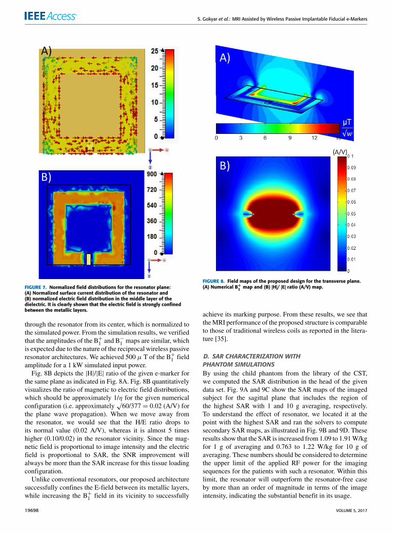
C. NUMERICAL RESULTS FOR FIELD DISTRIBUTIONSFig. 7A presents the normalized surface current distribu-tion ( EJc distribution normalized to the incident magneticfield), whereas Fig. 7B shows the normalized electric fieldmap (| EE| field normalized to incident electric field) at thedielectric layer between conductive metallization layers forthe resonance frequency of 123 MHz. From Fig. 7A, we caninfer that the magnetic field, coupled to the resonator atits resonance frequency, causes a surface current improve-ment (by 25-fold for this architecture) on the metallizationlayers. This results in improved B+1 field distribution, whichexplains the SNR improvement in the MR images.
Using a resonator in a lossy medium (e.g., inside a bio-logical tissue) introduces challenges due to the loading ofthe resonator. Lossy medium leads to a decreased qualityfactor and an increased SAR for the surrounding tissue.At this point, the E-field distribution, as illustrated in Fig. 7B,indicates that the electric field is confined to the dielectriclayer between the metallization layers and does not spillover to the surrounding tissue. This allows for a reduction ofthe interaction between the proposed structure and the envi-ronment. Therefore, we would foresee that the performanceof the resonator is improved in terms of loading and SARparameters compared to conventional resonator architectures.
As depicted in Fig. 8A, we computationally calculatedthe normalized B+1 map on the transverse plane by passing
VOLUME 5, 2017 19697
S. Gokyar et al.: MRI Assisted by Wireless Passive Implantable Fiducial e-Markers
FIGURE 7. Normalized field distributions for the resonator plane:(A) Normalized surface current distribution of the resonator and(B) normalized electric field distribution in the middle layer of thedielectric. It is clearly shown that the electric field is strongly confinedbetween the metallic layers.
through the resonator from its center, which is normalized tothe simulated power. From the simulation results, we verifiedthat the amplitudes of the B+1 and B−1 maps are similar, whichis expected due to the nature of the reciprocal wireless passiveresonator architectures. We achieved 500 µ T of the B+1 fieldamplitude for a 1 kW simulated input power.
Fig. 8B depicts the |H|/|E| ratio of the given e-marker forthe same plane as indicated in Fig. 8A. Fig. 8B quantitativelyvisualizes the ratio of magnetic to electric field distributions,which should be approximately 1/η for the given numericalconfiguration (i.e. approximately
√60/377 = 0.02 (A/V) for
the plane wave propagation). When we move away fromthe resonator, we would see that the H/E ratio drops toits normal value (0.02 A/V), whereas it is almost 5 timeshigher (0.10/0.02) in the resonator vicinity. Since the mag-netic field is proportional to image intensity and the electricfield is proportional to SAR, the SNR improvement willalways be more than the SAR increase for this tissue loadingconfiguration.
Unlike conventional resonators, our proposed architecturesuccessfully confines the E-field between its metallic layers,while increasing the B+1 field in its vicinity to successfully
FIGURE 8. Field maps of the proposed design for the transverse plane.(A) Numerical B+
1 map and (B) |H|/ |E| ratio (A/V) map.
achieve its marking purpose. From these results, we see thattheMRI performance of the proposed structure is comparableto those of traditional wireless coils as reported in the litera-ture [35].
D. SAR CHARACTERIZATION WITHPHANTOM SIMULATIONSBy using the child phantom from the library of the CST,we computed the SAR distribution in the head of the givendata set. Fig. 9A and 9C show the SAR maps of the imagedsubject for the sagittal plane that includes the region ofthe highest SAR with 1 and 10 g averaging, respectively.To understand the effect of resonator, we located it at thepoint with the highest SAR and ran the solvers to computesecondary SAR maps, as illustrated in Fig. 9B and 9D. Theseresults show that the SAR is increased from 1.09 to 1.91W/kgfor 1 g of averaging and 0.763 to 1.22 W/kg for 10 g ofaveraging. These numbers should be considered to determinethe upper limit of the applied RF power for the imagingsequences for the patients with such a resonator. Within thislimit, the resonator will outperform the resonator-free caseby more than an order of magnitude in terms of the imageintensity, indicating the substantial benefit in its usage.
19698 VOLUME 5, 2017

S. Gokyar et al.: MRI Assisted by Wireless Passive Implantable Fiducial e-Markers
FIGURE 9. SAR distribution results of the given design for the child dataset: (A) 1 g of averaging without resonator, (B) 1 g of averaging withresonator, (C) 10 g of averaging without resonator and (D) 10 g ofaveraging with resonator.
FIGURE 10. Experimental characterization of the proposed e-marker: (A)MRI of the proposed designs that are placed 2 mm away from each otherand consecutively fabricated onto the same dielectric. (B) B+
1 map of thegiven e-marker, which was computed using the double-angle method.
E. EXPERIMENTAL MRI CHARACTERIZATIONFig. 10A shows the MRI of the fabricated devices, immersedin the phantom described above, using the GrE sequence anda flip angle of 10◦. The provided MRI depicts that the signalintensity is higher in the vicinity of the resonators, whichis also proportional to the B+1 field distribution providedin Fig. 8A. The signal intensity profile along with the dashed
TABLE 1. Positioning accuracy of the proposed marker.
red line passing through the center of a resonator is presentedon the left side. It is clearly shown that the signal level isamplified by an order of magnitude in the vicinity of theresonator, which results in an approximately 15-fold SNRimprovement.
The brightness of certain regions close to the resonatorcan be seen, which occurs because of two reasons: 1) theinductive coupling of the transmit-field (B+1 improvement)and 2) the receive-field inductive coupling. The applied RFpower induces surface currents proportional to the resonatorQ-factor, which in return creates an effective B+1 field distri-bution in its vicinity (B+1Q ∼Q.B
+
1 ). The new flip angle (α)distribution will be proportional to this new B+1Q field dis-tribution (α ∼ γB+1Qτ , where γ is the gyromagnetic ratio).Hence, the transmit field contribution to the imaging signalwill be proportional to sin(α) ∼ sin(γQB+1 τ ) [36]. Thus,the image intensity distribution will depend on the qualityfactor and the B+1 distribution due to the spatial distributionof this flip angle.
Fig. 10B shows the experimental B+1 map distribution thatwas computed using the double-angle method [32]. Here,we see that the B+1 field is almost 6 times higher (12 µT/2 µT) in the vicinity of the resonator compared to remotepoints.
Once the spins are excited in the presence of a resonator,they emit a precise signal that is captured by the resonator andtransmitted to the receiver antennas. This process, known asreceive-field coupling, is proportional to the Q-factor of theresonator [37]. Hence, the overall image intensity enhance-ment profile will be proportional to themultiplication of thesetwo effects. (IQ = |I0Q sin(α)|, here note that α is positiondependent).
Marking precision results are reported in Table 1. Here, µxandµz are the mean of absolute errors between the actual andmeasured positions in x and z directions respectively, whereasµr is the mean error of the Euclidian distance. Increasingthe resolution of the acquired images allows us to positionthe marker more precisely. We can infer that the sub-mmpositioning accuracy using a reference marker-resonator paircan be achieved, which is comparable to previously reportedresults [16].
F. SUBDURAL ELECTRODE MARKINGSubdural electrodes are commonly used in epilepsy diag-noses to successfully determine the sites for recession in the
VOLUME 5, 2017 19699

S. Gokyar et al.: MRI Assisted by Wireless Passive Implantable Fiducial e-Markers
FIGURE 11. MRI of the proposed resonator-electrode pairs for ex-vivoapplications: (A) Optical image of the rabbit with a resonator-electrodepair positioned on its head. (B) MRI of the brain for the given imagingconfiguration. Vicinity of electrode-resonator pair is clearly visible andmarked on the same image.
brain [38]. As mentioned earlier, clinical MRI scans are notsuitable to show these electrodes due to the lack of 1H atomsin their content. Some magnetic content could be added tothese electrodes to make them MRI visible (actually darker),but this comes with a loss of data and increased artifacts
near them. Positions of the non-magnetic subdural electrodescannot be determined by MRI, so additional imaging modal-ities, e.g., X-ray, PET and CT, are required to correctlydetermine their locations. The proposed e-marker removesthis multi-modal imaging effort by its high-quality resonancecharacteristics.
Although a detailed analysis of the safety of intracranialEEG electrodes under MRI was previously conducted [39],their magnetic content prevents the use for GrE sequences.Hence, we fabricated an array of mimicked non-magneticsubdural electrodes. To mimic the operation of subdural elec-trodes, we deposited Ti/Au metals onto a 12.5 µm thick flex-ible polyimide film with a diameter of 4 mm and combinedthem with the resonators by sticking them to each other. Theoverall electrode-resonator pair was placed externally on thehead of a rabbit as shown in Fig. 11A.
Standard gradient echo sequences with different imagingparameters were applied to verify the operation of the res-onator. Although we presented the MRI that is acquired byusing a flip angle of 3◦ in Fig. 11B, we observed that itwould be as low as 1◦ or as high as 60◦ for this configuration.MRIs showed that we were able to clearly mark these elec-trodes with resonators whereas the other electrodes withoutresonators could not be distinguished in the image as shownin Fig. 11A. The resulting performance of the resonators ishigh even in the vicinity of the electrodes. Not only ismarkingpossible but also SNR enhancement, which can be clearlyseen in Fig. 11B. By adding resonators onto all of the elec-trodes, it would be possible to map each electrode using onlyMRI. All of the complications regarding the transportationof patients, mapping of electrodes, and use of CT, PET orX-ray imaging to obtain clear positioning of electrodes canthus be resolved, and positioning efforts can be significantlysimplified.
V. CONCLUSIONWe proposed, designed, fabricated and successfully demon-strated an MRI-visible high-quality resonator system that isflexible, smaller and potentially biocompatible to be used forin vivo applications including subdural electrode imaging.Variants of the proposed resonator can be used in interven-tional MRI devices and future MRI-visible smart implants.This architecture enables miniaturization down to sub-cmsizes (8mm× 8mm in this work) without sacrificing its prac-tical usage and performance. The proposed structure benefitsfrom the high inductance of a helical ring and the high parallelplate capacitance of multiple layers for the same conductivepath. Its frequency response can be conveniently tuned withinsub-cm footprint limits such that the operating frequency ofthe resonators can be in resonance with the imaging fre-quencies of clinical MRI devices simply by changing themetallization width, dielectric film thickness, and number oflayers or any combination of these parameters.
Although the present design causes SAR to increase byapproximately 90%, without exceeding the FDA or IECstandards for most of the clinical applications, it increases
19700 VOLUME 5, 2017

S. Gokyar et al.: MRI Assisted by Wireless Passive Implantable Fiducial e-Markers
SNR by over 15 times for the reported imaging practices andby approximately 5-fold for most the clinical applications.All of these results indicate that the proposed architectureholds great promise to be used in MRI to improve the imageintensity and, hence, the SNR in its vicinity. The proposedarchitecture does not limit conventional clinical practices,such as using PET and CT for the imaging of metallicobjects, or the imaging parameters such as TR and TE.
Integration of the proposed resonators with implants (e.g.subdural electrodes) during fabrication would furtherimprove the operational reliability of the devices and allowfor in vivo studies, which will be considered as a futurestep. Additionally, in future work, although the essentialconstituents of the proposed structure (Ti, Au, and PDMS)are all individually biocompatible, the biocompatibility ofthe overall structure should be verified before in vivoexperiments.
ACKNOWLEDGMENTSThe authors of this work would like to thankMr. Taner Demirfor his help in preparing the open coil system, Dr. VolkanAcikel for his valuable discussions about phantom recipes,and Prof. Kader Karli Oguz M.D. and Prof. Burçak BilginerM.D. for their recommendations and discussions regardingintracranial electrodes.
REFERENCES[1] P. C. Lauterbur, ‘‘Image formation by induced local interactions:
Examples employing nuclear magnetic resonance,’’ Nature, vol. 242,pp. 190–191, Mar. 1973.
[2] E. Atalar et al., ‘‘High resolution intravascular MRI and MRS by usinga catheter receiver coil,’’ Magn. Reson. Med., vol. 36, pp. 596–605,Oct. 1996, doi: 10.1002/mrm.1910360415.
[3] R. R. A. Syms, I. R. Young, C. A. Wadsworth, S. D. Taylor-Robinson,and M. Rea, ‘‘Magnetic resonance imaging duodenoscope,’’ IEEE Trans.Biomed. Eng., vol. 60, no. 12, pp. 3458–3467, Dec. 2013.
[4] R. R. A. Syms, I. R. Young, M. M. Ahmad, M. Rea, C. A. Wadsworth,and S. D. Taylor-Robinson, ‘‘Thin-film detector system for internal mag-netic resonance imaging,’’ Sens. Actuators A, Phys., vol. 163, pp. 15–24,Sep. 2010.
[5] K. Segkhoonthod, R. R. A. Syms, and I. R. Young, ‘‘Design of magneto-inductivemagnetic resonance imaging catheters,’’ IEEE Sensors J., vol. 14,no. 5, pp. 1505–1513, May 2014.
[6] G. Chen et al., ‘‘MRI-visible polymeric vector bearing CD3 single chainantibody for gene delivery to T cells for immunosuppression,’’ Biomateri-als, vol. 30, pp. 1962–1970, Apr. 2009.
[7] P. Pang et al., ‘‘An MRI-visible non-viral vector bearing GD2 single chainantibody for targeted gene delivery to human bone marrow mesenchymalstem cells,’’ PLoS ONE, vol. 8, no. 10, p. e76612, 2013, doi: 10.1371/journal.pone.0076612.
[8] J. W. Gilbert et al., ‘‘Guidance of magnetic resonance imaging and place-ment of skin-marker localization devices,’’ J. Neurosurg. Sci., vol. 55, no. 2,pp. 85–88, 2011.
[9] E. R. Cosman and T. S. Roberts, ‘‘CT and MRI visible index markers forstereotactic localization,’’ U.S. Patent 6 419 680 B1, Jul. 16, 2002.
[10] J. E. Baumgartner, ‘‘MRI-compatible fiducial markers and methods forusing the same,’’ U.S. Patent 2015 0 011 868 A1, Jan. 8, 2015.
[11] C. C. Parker, A. Damyanovich, T. Haycocks, M. Haider, A. Bayley, andC. N. Catton, ‘‘Magnetic resonance imaging in the radiation treatmentplanning of localized prostate cancer using intra-prostatic fiducial markersfor computed tomography co-registration,’’ Radioterapy Oncol., vol. 66,no. 2, pp. 217–224, 2003.
[12] M. Burl, G. A. Coutts, and I. R. Young, ‘‘Tuned fiducial markers to identifybody locations with minimal perturbation of tissue magnetization,’’Magn.Resonance Med., vol. 36, no. 3, pp. 491–493, 1996.
[13] H. H. Quick et al., ‘‘Wireless active catheter visualization: Passive decou-pling methods and their impact on catheter visibility,’’ in Proc. 13th Int.Soc. Magn. Reson. Med., 2005, p. 2164.
[14] R. R. A. Syms, I. R. Young, M. M. Ahmad, S. D. Taylor-Robinson, andM. Rea, ‘‘Magneto-inductive catheter receiver for magnetic resonanceimaging,’’ IEEE Trans. Biomed. Eng., vol. 60, no. 9, pp. 2421–2431,Sep. 2013
[15] P. A. Bottomley, ‘‘Turning up the heat on MRI,’’ J. Amer. College Radiol.,vol. 5, no. 7, pp. 853–855, Jul. 2008.
[16] M. Rea et al., ‘‘Sub-pixel localisation of passive micro-coil fiducial mark-ers in interventionalMRI,’’Magn. Reson.Mater. Phys., vol. 22, no. 2, p. 71,2009, doi:10.1007/s10334-008-0143-1.
[17] P. S. LaViolette, S. D. Rand, M. Raghavan, B. M. Ellingson,K. M. Schmainda, and W. Mueller, ‘‘Three-dimensional visualizationof subdural electrodes for presurgical planning,’’ Neurosurgery, vol. 68,pp. 152–161, Mar. 2011.
[18] M. A. Silberbusch, M. I. Rothman, G. K. Bergey, G. H. Zoarski,and M. T. Zagardo, ‘‘Subdural grid implantation for intracranial EEGrecording: CT and MR appearance,’’ Amer. J. Neuroradiol., vol. 19,pp. 1089–1093, Jun. 1998
[19] J. X. Tao, S. Hawes-Ebersole, M. Baldwin, S. Shah, R. K. Erickson,J. S. Ebersole, ‘‘The accuracy and reliability of 3D CT/MRI co-registrationin planning epilepsy surgery,’’ Clin. Neurophysiol., vol. 120, no. 4,pp. 748–753, 2009.
[20] S. S. Dalal, E. Edwards, H. E. Kirsch, N. M. Barbaro, R. T. Knight, andS. S. Nagarajan, ‘‘Localization of neurosurgically implanted electrodesvia photograph–MRI–radiograph coregistration,’’ J. Neurosci. Methods,vol. 174, no. 1, pp. 106–115, 2008.
[21] B. J. Erickson and C. R. Jack, ‘‘Correlation of single photon emissionCT with MR image data using fiduciary markers,’’ Amer. J. Neuroradiol.,no. 14, pp. 713–720, May/Jun. 1993.
[22] M. Nelles, R. Koenig, J. Kandyba, C. Schaller, H. Urbach, ‘‘Fusion of MRIand CT with subdural grid electrodes,’’ Zentralbl Neurochirurgie, vol. 65,no. 4, pp. 174–179, Nov. 2004
[23] M. S. Khennouche, F. Gadot, A. Lustrac, M .P. Quinot, L. Darrasse, andJ. C. Ginefri, ‘‘The use of metamaterials: A solution to improve the perfor-mance of radiofrequency coil for magnetic resonance imaging (MRI)?’’Metamorphose-VI, vol. 4, pp. 468–470, Oct. 2011.
[24] F. W. Grover, Inductance Calculations: Working Formulas and Tables.New York, NY, USA: Dover, 2004.
[25] I. Bahl, Lumped Elements for RF and Microwave Circuits. Norwood, MA,USA: Artech House, 2003, p. 81.
[26] F. Bilotti, A. Toscano, and L. Vegni, ‘‘Design of spiral and multiple split-ring resonators for the realization of miniaturized metamaterial samples,’’IEEE Trans. Antennas Propag., vol. 55, no. 8, pp. 2258–2267, Aug. 2007,doi: 10.1109/TAP.2007.901950.
[27] J. Wang and O. Fujiwara, ‘‘Comparison and evaluation of electromagneticabsorption characteristics in realistic human head models of adult andchildren for 900-MHz mobile telephones,’’ IEEE Trans. Microw. TheoryTechn., vol. 51, no. 3, pp. 966–971, Mar. 2003.
[28] E. Conil, A. Hadjem, F. Lacroux, M. F. Wong, and J. Wiart, ‘‘Variabilityanalysis of SAR from 20 MHz to 2.4 GHz for different adult and childmodels using finite-difference time-domain,’’ Phys. Med. Biol., vol. 53,pp. 1511–1525, 2008.
[29] M. Kozlov and R. Turner, ‘‘A comparison of Ansoft HFSS and CSTmicrowave studio simulation software for multi-channel coil designand SAR estimation at 7T MRI,’’ PIERS, vol. 6, no. 4, pp. 395–399,2010
[30] An Internet Resource for the Calculation of the Dielectric Propertiesof Body Tissues in the Frequency Range 10 Hz—100 GHz. Accessed:Apr. 16, 2017. [Online]. Available: http://niremf.ifac.cnr.it/tissprop/
[31] V. Acikel, O. Ulutan, A. C. Ozen, B. Akin, Y. Eryaman, and E. Atalar,‘‘A novel MRI based electrical properties measurement technique,’’ inProc. Int. Soc. Mag. Reson. Med., no. 21, p. 4430, Apr. 2013.
[32] C. H. Cuningham, J. M. Pauly, and K. S. Nayak, ‘‘Saturated double-anglemethod for rapid B1+ mapping,’’ Magn. Reson. Med., vol. 55, no. 6,pp. 1326–1333, 2006.
[33] G. Thörmer, N. Garnov, M. Moche, J. Haase, T. Kahn, and H. Busse,‘‘Simultaneous 3D localization of multiple MR-visible markers in fullyreconstructed MR images: Proof-of-concept for subsecond position track-ing,’’ Magn. Reson. Imag., vol. 30, no. 3, pp. 371–381, 2012.
[34] J. C. Ginefri, E. Durand, L. Darrasse, ‘‘Quick measurement of nuclearmagnetic resonance coil sensitivity with a single-loop probe,’’ Rev. Sci.Instrum., vol. 70, no. 12, p. 4730, 1999.
VOLUME 5, 2017 19701
S. Gokyar et al.: MRI Assisted by Wireless Passive Implantable Fiducial e-Markers
[35] J. T. Vaughan and J. R. Griffiths, RF Coils for MRI. West Sussex, U.K.,Wiley, 2010, pp. 17–25.
[36] D. G. Nishimura, The Principles of Magnetic Resonance Imaging. Stan-ford, CA, USA: Stanford Univ., Apr. 1996, p. 114.
[37] S. Wang, J. Murphy-Boesch, H. Merkle, A. P. Koretsky, and J. H. Duyn,‘‘B1 homogenization in MRI by multilayer coupled coils,’’ IEEE Trans.Med. Imag., vol. 28, no. 4, pp. 551–554, Apr. 2009.
[38] E. Asano, C. Juhasz, A. Shah, S. Sood, and H. T. Chugani, ‘‘Role ofsubdural electrocorticography in prediction of long-term seizure outcomein epilepsy surgery,’’ Brain, J. Neurol., vol. 132, no. 4, pp. 1038–1047,2009.
[39] D.W. Carmichael et al., ‘‘Safety of localizing epilepsymonitoring intracra-nial electroencephalograph electrodes using MRI: Radiofrequency-induced heating,’’ J. Magn. Reson. Imag., vol. 28, no. 5, pp. 1233–1244,2008.
SAYIM GOKYAR received the B.Sc. and M.Sc.degrees in electrical and electronics engineer-ing in 2009 and 2011, respectively. He iscurrently pursuing the Ph.D. degree with the Elec-trical and Electronics Engineering Department,Bilkent University, Ankara, Turkey. His researchinterests include wireless sensors and designingimplantable devices.
AKBAR ALIPOUR received the Ph.D. degree fromthe Department of Electrical and Electronics Engi-neering, Bilkent University, Ankara. His researchinterests include thin-film microwave structures,which are used for magnetic resonance imag-ing (MRI) marking and wireless sensing. He hasbeen involved in the development of devices,which are mainly used in interventional MRI andmedical implants.
EMRE UNAL received the B.S. degree inelectrical and electronics engineering fromHacettepe University, Ankara, Turkey, in 2005.He is currently a Full-Time Research Engineerunder the supervision of Prof. H. V. Demir,with the Institute of Materials Science andNanotechnology, Bilkent University, Ankara,where he is involved in the development ofmicrowave and optoelectronic devices.
ERGIN ATALAR received the B.S. degree fromBogazici University in 1985, the M.S. degree fromMiddle East Technical University in 1987, andthe Ph.D. degree from Bilkent University in 1991,all in electrical engineering. He joined the JohnsHopkins University, where he became a Professorof radiology, biomedical engineering, and elec-trical and computer engineering and the Direc-tor of the Center for Image Guided Interventions.He is currently a Professor with the Department
of Electrical and Electronics Engineering and the Director of the NationalMagnetic Resonance Research Center, Bilkent University. His research inter-ests include magnetic resonance imaging and image guided interventions.In 2006, Ergin Atalar received the TUBITAK Science Award.
HILMI VOLKAN DEMIR (M’04–SM’11) receivedthe B.Sc. degree in electrical and electronicsengineering from Bilkent University, Ankara,Turkey, in 1998 and the M.Sc. and Ph.D.degrees in electrical engineering from StanfordUniversity, Stanford, CA, USA, in 2000 and 2004,respectively. In 2004, he joined Bilkent Univer-sity, where he is currently a Professor with jointappointments with the Department of Electricaland Electronics Engineering and the Department
of Physics. He is also with UNAM-the Institute of Materials Science andNanotechnology. He is a fellow of National Research Foundation in Singa-pore and a Professor with Nanyang Technological University. His researchinterests include the development of innovative optoelectronic and RFdevices. He was a recipient of the European Union Marie Curie Fellowship,the Turkish National Academy of Sciences Distinguished Young ScientistAward, the European Science Foundation-European Young InvestigatorAward, and the Nanyang Award for Research Excellence.
19702 VOLUME 5, 2017