magnetic lock with display panel - moniteqmanual.pdfdual magnetic bond sensing switches...
TRANSCRIPT
INSTRUCTION MANUAL
Model CC-8946 7/17
Magnetic Lock with
Display Panel
MONITEQ, Inc.
2
INSTRUCTION MANUAL
Model CC-8946
Magnetic Lock with Display Panel
Table of contents
1. Introduction 3
2. Specifications 4
3. Supplied equipment 5
4. Functions of controls and indicators 6
5. Installation 7
6. Operation 12
7. Theory of operation and troubleshooting 13
3
1. INTRODUCTION
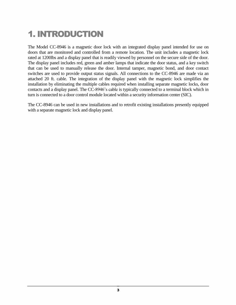
The Model CC-8946 is a magnetic door lock with an integrated display panel intended for use on
doors that are monitored and controlled from a remote location. The unit includes a magnetic lock
rated at 1200lbs and a display panel that is readily viewed by personnel on the secure side of the door.
The display panel includes red, green and amber lamps that indicate the door status, and a key switch
that can be used to manually release the door. Internal tamper, magnetic bond, and door contact
switches are used to provide output status signals. All connections to the CC-8946 are made via an
attached 20 ft. cable. The integration of the display panel with the magnetic lock simplifies the
installation by eliminating the multiple cables required when installing separate magnetic locks, door
contacts and a display panel. The CC-8946’s cable is typically connected to a terminal block which in
turn is connected to a door control module located within a security information center (SIC).
The CC-8946 can be used in new installations and to retrofit existing installations presently equipped
with a separate magnetic lock and display panel.
4
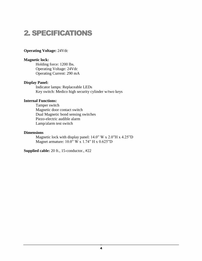
2. SPECIFICATIONS
Operating Voltage: 24Vdc
Magnetic lock:
Holding force: 1200 lbs.
Operating Voltage: 24Vdc
Operating Current: 290 mA
Display Panel:
Indicator lamps: Replaceable LEDs
Key switch: Medico high security cylinder w/two keys
Internal Functions:
Tamper switch
Magnetic door contact switch
Dual Magnetic bond sensing switches
Piezo-electric audible alarm
Lamp/alarm test switch
Dimensions
Magnetic lock with display panel: 14.0” W x 2.0”H x 4.25”D
Magnet armature: 10.0” W x 1.74” H x 0.625”D
Supplied cable: 20 ft., 15-conductor., #22

5
3. SUPPLIED EQUIPMENT
The CC-8946 consists of the Magnetic Lock with Display Panel, Magnetic Armature and various
accessories and mounting hardware to facilitate installation. The table below lists all of the items
that comprise the Model CC-8946 along with a brief description of each to aid in identification
and use.
QTY ITEM PURPOSE
1 Magnetic Lock with
Display Panel
Mounts on the door header to secure the door and display
the door status
1 Magnetic Armature Mounts on the door so as to align with and bond to the
magnetic lock when the door is secured.
1 Mounting Template Used to accurately locate both the Magnetic Lock and
Armature.
1 Sex bolt/nut and roll pin
kit
Used to mount the Armature to the door
1 Mounting screw kit Used to mount Magnetic Lock with Display Panel to the
door frame
2 Key for key switch Used to manually release the magnetic lock using the key
switch on the Display Panel
1 Instruction Manual Installation, operation and troubleshooting instructions
6
4. FUNCTIONS OF CONTROLS AND
INDICATORS
The functions of the items on the display panel are described below:
Key switch - Used to release the magnetic lock by momentarily turning the key clockwise. The
key cannot be removed in this released position.
Red Lamp - Indicates that the door is open. (controlled by the internal door contact switch.)
Green Lamp – Indicates that the door is secured (controlled by the internal magnetic bond
sensor switch.)
Amber Lamp - Indicates that the door is not secure (controlled by the internal magnetic bond
sensor switch and the control module in the SIC). When flashing, indicates that the push bar has
been pressed and that the countdown timer (typically set to 15 seconds) has been activated.
Audible Alarm - When sounding continuously indicates that the tamper switch within the CC-
8946 has opened. (controlled by the internal tamper switch and by the control module in the
SIC.) When sounding on-and-off indicates that the push bar has been pressed and that the 15
second count down timer has been activated. When sounding continuously indicates that the
unit’s cover has been opened.
Test switch - When pressed illuminates all three indicator lamps and sounds the audible alarm
and the corresponding items on the Control Module in the SIC. (Accessed using a paper clip or
similar item through the small hole located near the center of the underside of the Display Panel.)

7
5. INSTALLATION
Installation of the CC-8946 consists of mounting the Magnetic Lock/Display Panel and the
Armature, and then connecting the attached cable (via a terminal block) to the cable that runs to
the associated Door Control Module.
5.1 Mechanical Installation
Figure 5-1, Elevation View
READ THOROUGHLY BEFORE INSTALLING
Handle electro-magnets and armatures carefully. Any damage to the mating surfaces may
significantly reduce holding efficiency.
The Electro-magnet assembly mounts firmly and rigidly to the underside of the header on the
stop side of the door. The armature mounts to the face of the door with special hardware for
proper floating action to assure total mating with the face of the electro-magnet.
Note from the supplied template that a 2-1/2” minimum reveal is required to assure rigid
mounting of the electro-magnet assembly. If this minimum is not met see Fig. 1 to determine the
need for either a filler Plate or an angle bracket.
Mark the door and frame for drilling in accordance with the supplied template dimensions. All
measurements are to be made with the door in the closed position.
Follow this 4-step mounting process:
8
STEP 1 - FRAME PREPARATION
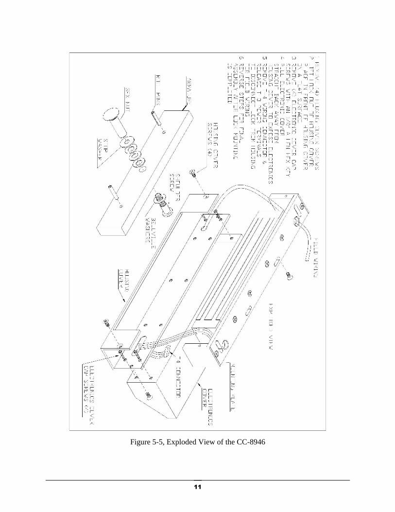
Remove the housing cover prior to lock installation (see Figure 5-5 Exploded View). Prepare the
frame for the electro-magnetic lock assembly by drilling for #14 sheet metal screws or drilling
and tapping for 1/4-20 machine screws and external tooth lock washers, (use the large slotted
holes only) tightening the screws just enough to hold unit in place. Route the attached 20 ft.
cable through the frame to the location where it will be connected to the cable going to the SIC.
STEP 2 - ARMATURE PREPARATION (Figure 3)
Prepare armature for mounting: Note that the armature has two 3/16 dia. holes open from the back
only. Press the two spring pins provided into these holes. Tap pins gently until they are firmly seated
in the holes being extremely careful not to mar the face of the armature.
Insert one spring washer on the 5/16 #18 shoulder screw and then insert the screw thru the armature.
Add three conical spring washers over shoulder and flat stop washer. (Per diagram enclosed in
armature kit.)
STEP 3 - ARMATURE MOUNTING
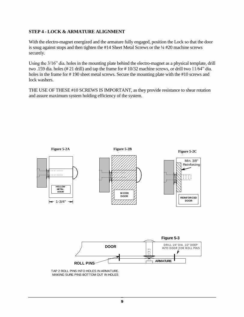
THRU BOLT MOUNTING IN HOLLOW METAL DOORS (Figure 5-2A)
(Dimensions shown are for standard 1-3/4” thick doors)
Drill an 11/32” hole through the door. Enlarge the hole in the outside face to ½” for the knurled sex
nut. Be sure that the spring pins pocket and float freely in the ¼” holes in the door. If not, remove the
armature and enlarge the holes in the door. Insert the shoulder screw/armature assembly thru the face
of the door, being sure that the spring washers remain over the shoulder, and hold firmly against the
door by pushing directly on the head of screw. Insert the sex nut from the opposite face and assemble.
When the armature is floating freely, tighten the 5/16 #18 shoulder screw fully and securely with a
5/32 Allen wrench.
THRU BOLT MOUNTING IN SOLID CORE WOODEN DOOR (Figure 5-2B)
Drill a ½” hole through the door. Insert the shoulder screw/armature assembly thru the face of the
door, being sure that spring washers remain over the shoulder, and hold firmly against the door by
pushing directly on the head of the screw. Insert the sex nut from the opposite face and assemble.
When the armature is floating freely, tighten the 5/16 #18 shoulder screw fully and securely with a
5/32 Allen wrench.
MACHINE SCREW MOUNTING (Figure 5-2C)
The door must be properly reinforced to a 3/8” minimum thickness and structured for a 1200 lb. load.
Drill and tap thru the reinforcing for a 1/15 #18 machine screw. Insert the shoulder screw/armature
assembly, being sure that the spring washers remain over the shoulder and the flat washer is between
the shoulder and the face of door. When the armature is floating freely, tighten the 5/16 #18 shoulder
screw fully and securely with a 5/32 Allen wrench.
9
STEP 4 - LOCK & ARMATURE ALIGNMENT
With the electro-magnet energized and the armature fully engaged, position the Lock so that the door
is snug against stops and then tighten the #14 Sheet Metal Screws or the ¼ #20 machine screws
securely.
Using the 3/16” dia. holes in the mounting plate behind the electro-magnet as a physical template, drill
two .159 dia. holes (# 21 drill) and tap the frame for # 10/32 machine screws, or drill two 11/64” dia.
holes in the frame for # 190 sheet metal screws. Secure the mounting plate with the #10 screws and
lock washers.
THE USE OF THESE #10 SCREWS IS IMPORTANT, as they provide resistance to shear rotation
and assure maximum system holding efficiency of the system.
figure 2-A
HOLLOW
METAL
DOOR
1-3/4"
figure 2-B
W OOD
DOOR
figure 2-C
Min. 3/8"
Reinforcing
REINFORCED
DOOR
ROLL PINS
DOOR
ARMATURE
D R ILL 1/4 " D IA. 1/2" D EEPIN TO D OOR F OR R OLL PIN S
figure 3
TAP 2 ROLL PINS INTO HOLES IN ARMATURE.
MAKING SURE PINS BOTTOM OUT IN HOLES
Figure 5-2A Figure 5-2B Figure 5-2C
Figure 5-3
10
VIO
GRY
BLU
GRN
YEL
ORG
RED
BRN
BLK
Common
+24Vdc
Push Bar Switch
WHT
Red Lamp
Green Lamp
Yellow Lamp
Buzzer
3 kOhm Sense
Lock Power In
Terminal
block at door
(Not supplied)
RED/BLK
RED/YEL
RED/GRN
ALPHA 1181/15C cable
(20 ft. supplied)
Push Bar
Switch (N/C)
Direct to magnet
N/C
Common
Magnetic Bond
Status Output
Relay
N/O
2
1
3
4
5
6
8
7
9
10
PA
IR
11
12
13
14
PA
IRP
AIR
PA
IRP
AIR
PA
IR
15
16
Cab
le t
o C
on
trol
Mo
du
le
BLK
WHT
RED
BLK
YEL
BLK
BLU
GRN
BLK
BLK
BRN
BLK
Not used
CC-8946
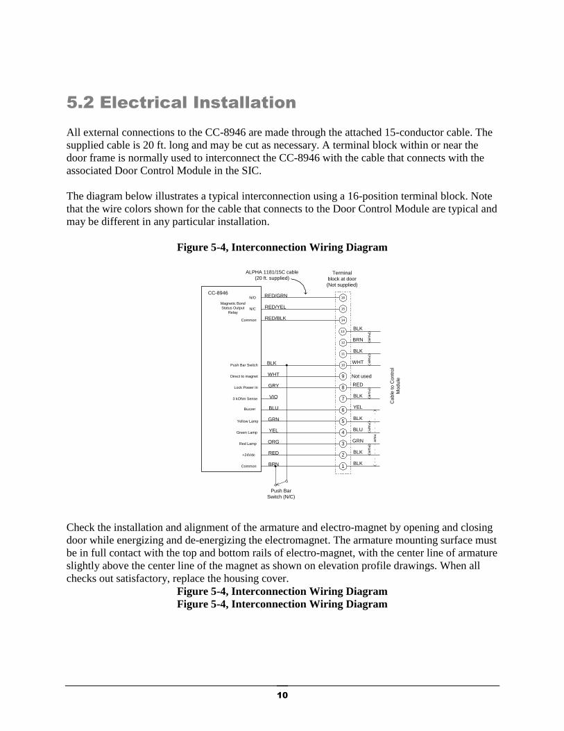
5.2 Electrical Installation
All external connections to the CC-8946 are made through the attached 15-conductor cable. The
supplied cable is 20 ft. long and may be cut as necessary. A terminal block within or near the
door frame is normally used to interconnect the CC-8946 with the cable that connects with the
associated Door Control Module in the SIC.
The diagram below illustrates a typical interconnection using a 16-position terminal block. Note
that the wire colors shown for the cable that connects to the Door Control Module are typical and
may be different in any particular installation.
Figure 5-4, Interconnection Wiring Diagram
Check the installation and alignment of the armature and electro-magnet by opening and closing
door while energizing and de-energizing the electromagnet. The armature mounting surface must
be in full contact with the top and bottom rails of electro-magnet, with the center line of armature
slightly above the center line of the magnet as shown on elevation profile drawings. When all
checks out satisfactory, replace the housing cover.
Figure 5-4, Interconnection Wiring Diagram
Figure 5-4, Interconnection Wiring Diagram
11
Figure 5-5, Exploded View of the CC-8946
12
6. OPERATION
General
During normal operation the CC-8946 remains in a Secure Mode until someone requests egress
by pressing on the Push Bar. This causes a timing sequence to begin which when completed,
releases the door. An operator stationed at the SIC may intervene at any time by using controls
on the Control Module associated with that door.
Secure Mode
The CC-8946 is normally in the Secure Mode. In this mode the Green and Amber lamps are on,
indicating that the door is closed and the magnet is bonded to the armature.
Egress Request Mode
When an individual presses the push bar a signal is sent from the CC-8946 to the control module
in the SIC. The control module then begins a timing sequence, typically 15 seconds long. The
amber lamp begins flashing and the audible alarm sounds an on-off pattern. The duration of the
Egress Request Mode is set within the control module.
Released Mode
Upon completion of the Egress Request Mode the Control Module removes the power to the
magnetic lock, releasing the door. The door may then be opened to provide egress. When the
door re-closes the system returns to the Secure Mode.
Operator Intervention
The operator at the SIC may intervene at any time using controls on the Control Module to
change the sequence of events. Refer to the documentation for the Control Module for details.

13
7. THEORY OF OPERATION AND
TROUBLESHOOTING
General
The CC-8946 operates together with a Control Module located in a Security Information Center
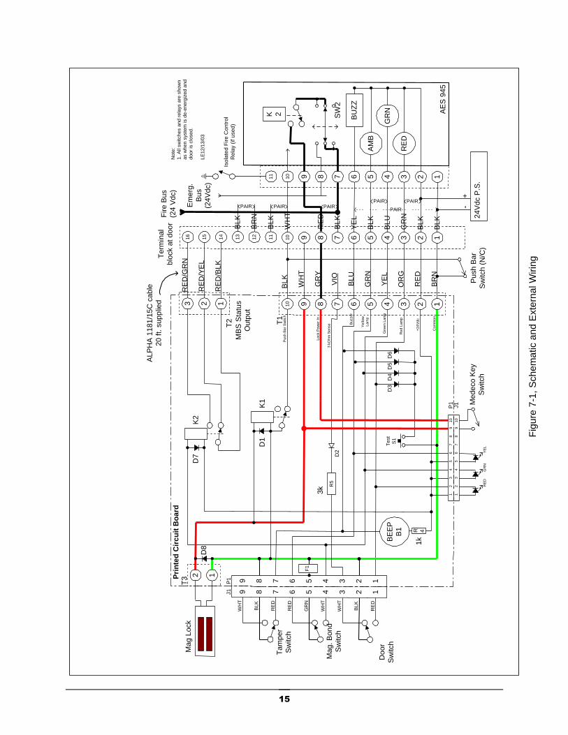
(SIC). Figure 7-1 is a schematic diagram of the Model CC-8946 showing the interconnections to
the Control Module in the SIC. It is supplied as an aid to understanding both the operation of the
CC-8946 itself and its connections to the Control Module.
Power to the magnetic lock is routed from the Control Module through T1, Pin 8, then through
the Key Switch S5 to the magnet.
Sensors within the CC-8946 monitor the status of the door, magnetic lock and push bar and route
this information to the control unit through T1 and the interconnecting cable. The Control
Module uses this information to control the magnetic lock and the status of the indicator lamps
and audible alarm on the CC-8946’s display panel.
Indicators and Audible Alarm
The three indicator lamps and the audible alarm all have one side connected to +24 Vdc from Pin
2 of T1. The other side of each device is controlled by both external connections to the Control
Module and by sensing switches within the CC-8946.
The Red lamp is controlled by the internal Door Switch (S4). When the door is open this switch
is closed, connecting the common return path to the red lamp.
The Green and Amber lamps are connected to the Magnetic Bond Switch S3. When the magnet
is energized and bonded to the armature, S3 connects the common return path to the Green lamp
L2. When the magnet and armature are not bonded, S3 connects the common return path to the
Amber lamp L3. The Control Module may also activate the Amber Lamp L3 by applying the
common return path through T1, Pin 5. This occurs during the Egress Request Mode.
Fuse F1 protects the magnetic bond reed switches against currents in excess of 200mA. These
reed switches are susceptible to damage if a voltage source is inadvertently applied during
installation. F1 automatically resets itself after the voltage causing the excess current to be
removed.
The Audible Alarm B1 is controlled by the Tamper Switch S2 and by the Control Module
through T1, Pin 6. The Tamper Switch S2 connects the common return path to B1 when the
cover of the CC-8946 is removed.
Test Switch - Applies the common return path to all three lamps and B1 (through diodes D3,
D4, D5 and D6). This provides a means of testing the lamps and audible alarm. Note that this test
also activates the lamps and audible alarm on the Control Module.
Relay K1 - is controlled by the power to the magnet and its contacts shunt the external push bar
switch when the magnet is energized.

14
Relay K2 - is controlled by the Magnetic Bond Switch S3. The output contacts of K2 are
connected to the red/green, red/yellow and red/black wires in the interconnecting cable. These
outputs are intended for use with an external device such as an automatic door opener.
Electromagnet – The electromagnet operates on a nominal 24Vdc and draws approximately 300
mA when energized. Diode D8 is across the magnet terminals to suppress voltage spikes that can
be generated when the magnet de-energizes.
Table 2, Status of the Signals on the interconnecting cable in the Secure Mode.
Wire Color Function Signal status in Secure Mode
Brown Common reference for all signals 0 Vdc
Red Fixed +24 Vdc supply voltage from control
module
+24 Vdc
Orange Red lamp, controlled by internal door switch 0 Vdc
Yellow Green lamp, controlled by internal magnetic bond
switch
0 Vdc
Green Yellow lamp, controlled by internal magnetic
bond switch and control module
+24 Vdc
Blue Audible alarm, controlled by internal tamper
switch and control module
+24Vdc
Violet 3kohn supervised door switch output 3kohm
Gray Switched +24 Vdc magnet power from the
control module
+24 Vdc
White Direct input to magnet, Not used n/a
Black Push bar switch output, controlled by push bar
and relay K1
0 Vdc
Red/Black MBS Status Output - Common relay contact Connected to Red/Green wire
Red/Yellow MBS Status Output - N/C relay contact Open
Red/Green MBS Status Output - N/O relay contact Connected to Red/Black wire
Pink Spare
Gray Spare
15
Fig
ure
7-1
, S
ch
em
atic a
nd
Exte
rna
l W
irin
g
2 134568 7910
RE
D
GR
N
AM
B
BU
ZZ
BL
K
BL
K 24
Vd
c P
.S.
+-
GR
N
BL
U
BL
K
YE
L
WH
T
11
2 134568 7910
Iso
late
d F
ire
Co
ntr
ol
Re
lay (
if u
se
d)
Tam
pe
r
Sw
itch
Mag. B
on
d
Sw
itch
VIO
GR
Y
BL
U
GR
N
YE
L
OR
G
RE
D
BR
N
BL
K
WH
T
GR
N
RE
D
RE
D
BLK
WH
T
Fire B
us
(24
Vd
c)
SW
2
K 2
Em
erg
.
Bu
s
(24
Vd
c)
AE
S 9
45
Note
:
1.
All
sw
itches a
nd r
ela
ys a
re s
how
n
as w
hen s
yste
m is d
e-e
nerg
ized a
nd
door
is c
losed.
LE
12/1
3/0
3
Co
mm
on
+2
4V
dc
T1
2 134568 7R
5
BE
EP
B1 R 4
D2
D3
D4
D6
D5
Test
S1
Mag L
ock
2 1
T3
Pu
sh
Ba
r S
witch
RE
D
BLK
WH
T
910
T2
WH
T
Re
d L
am
p
Gre
en
La
mp
Ye
llo
w
La
mp
Bu
zze
r
3 k
Oh
m S
en
se
Lo
ck P
ow
er
In
Mede
co K
ey
Sw
itch
PAIR
RE
D
Term
inal
blo
ck a
t d
oo
r
K1
D1
K2
D7
F1
MB
S S
tatu
s
Ou
tput
11
12
13
14
15
16
123
RE
D/B
LK
RE
D/Y
EL
RE
D/G
RN
BL
K
BL
K
BL
K
BR
N
Pri
nte
d C
irc
uit
Bo
ard
9 12345678
9 12345678P1
J1
AL
PH
A 1
18
1/1
5C
cab
le
20
ft. s
up
plie
d
PAIRPAIRPAIRPAIRPAIR
12
34
75
68
10
9
12
34
75
68
10
9
P1
J1
RE
DG
RN
YE
L
D8
Pu
sh B
ar
Sw
itch (
N/C
)
3k
1k
Doo
r
Sw
itch

16
MONITEQ Inc. 213 Church St.
Greensboro , MD 21639
Tel: 1-800-989-9891 1-410-827-8870 Fax: 1-703-549-1090 Email: [email protected] Web: www.moniteq.com
12/03-25
One Year Limited Warranty
MONITEQ products are warranted to be free from factory defects for a period of one year from the date of shipment. The repair or replacement of a defective part shall be at the option of the factory when the product is shipped prepaid and insured by the owner. This warranty is void in cases of abuse, misuse, mishandling, or repair by unauthorized persons. This warranty is given in lieu of all other warranties expressed or implied. MONITEQ is not liable for incidental or consequential damages resulting from the operation or failure of this product. The warranty recognizes any and all rights you may have under appropriate state law.