magnaloy manifold
TRANSCRIPT
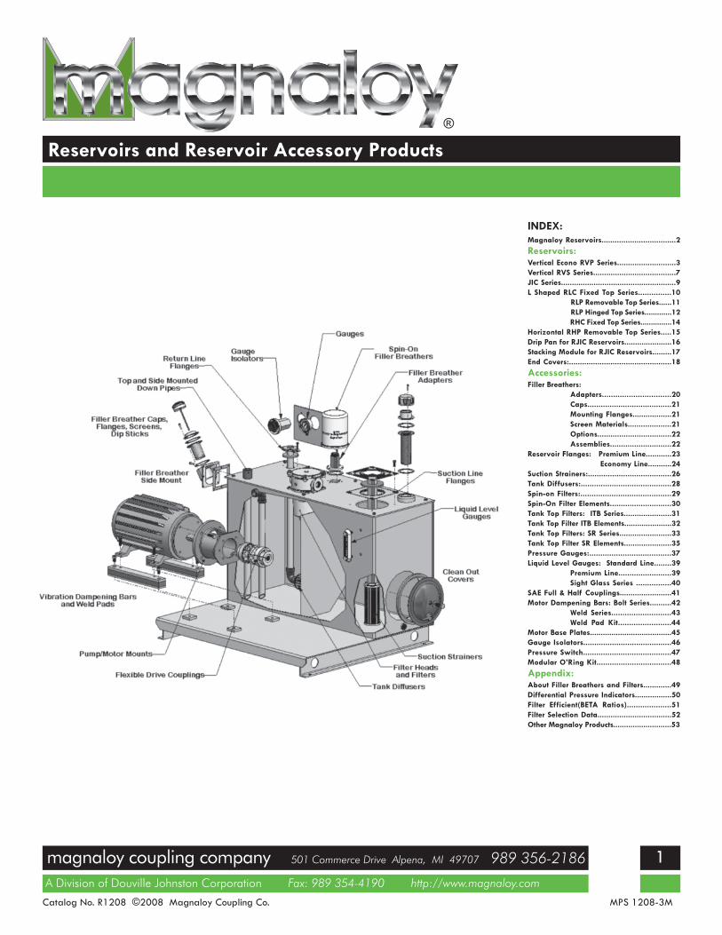
Reservoirs and Reservoir Accessory Products
A Division of Douville Johnston Corporation Fax: 989 354-4190 http://www.magnaloy.com
magnaloy coupling company 501 Commerce Drive Alpena, MI 49707 989 356-2186
Catalog No. R1208 ©2008 Magnaloy Coupling Co. MPS 1208-3M
1
®
INDEX:Magnaloy Reservoirs..................................2Reservoirs:Vertical Econo RVP Series...........................3Vertical RVS Series......................................7JIC Series.....................................................9L Shaped RLC Fixed Top Series...............10
RLP Removable Top Series......11RLP Hinged Top Series.............12RHC Fixed Top Series...............14
Horizontal RHP Removable Top Series.....15Drip Pan for RJIC Reservoirs......................16Stacking Module for RJIC Reservoirs.........17End Covers:...............................................18Accessories:Filler Breathers:
Adapters...............................20Caps......................................21Mounting Flanges..................21Screen Materials....................21Options..................................22Assemblies............................22
Reservoir Flanges: Premium Line............23Economy Line...........24
Suction Strainers:......................................26Tank Diffusers:.........................................28Spin-on Filters:.........................................29Spin-On Filter Elements............................30Tank Top Filters: ITB Series......................31Tank Top Filter ITB Elements......................32Tank Top Filters: SR Series........................33Tank Top Filter SR Elements......................35Pressure Gauges:.....................................37Liquid Level Gauges: Standard Line........39
Premium Line........................39Sight Glass Series ................40
SAE Full & Half Couplings........................41Motor Dampening Bars: Bolt Series..........42
Weld Series...........................43Weld Pad Kit........................44
Motor Base Plates......................................45Gauge Isolators........................................46Pressure Switch........................................47Modular O’Ring Kit..................................48Appendix:About Filler Breathers and Filters.............49Differential Pressure Indicators.................50Filter Efficient(BETA Ratios)....................51Filter Selection Data..................................52Other Magnaloy Products...........................53
magnaloy coupling company 501 Commerce Drive Alpena, MI 49707 989 356-2186
A Division of Douville Johnston Corporation Fax: 989 354-4190 http://www.magnaloy.com
2
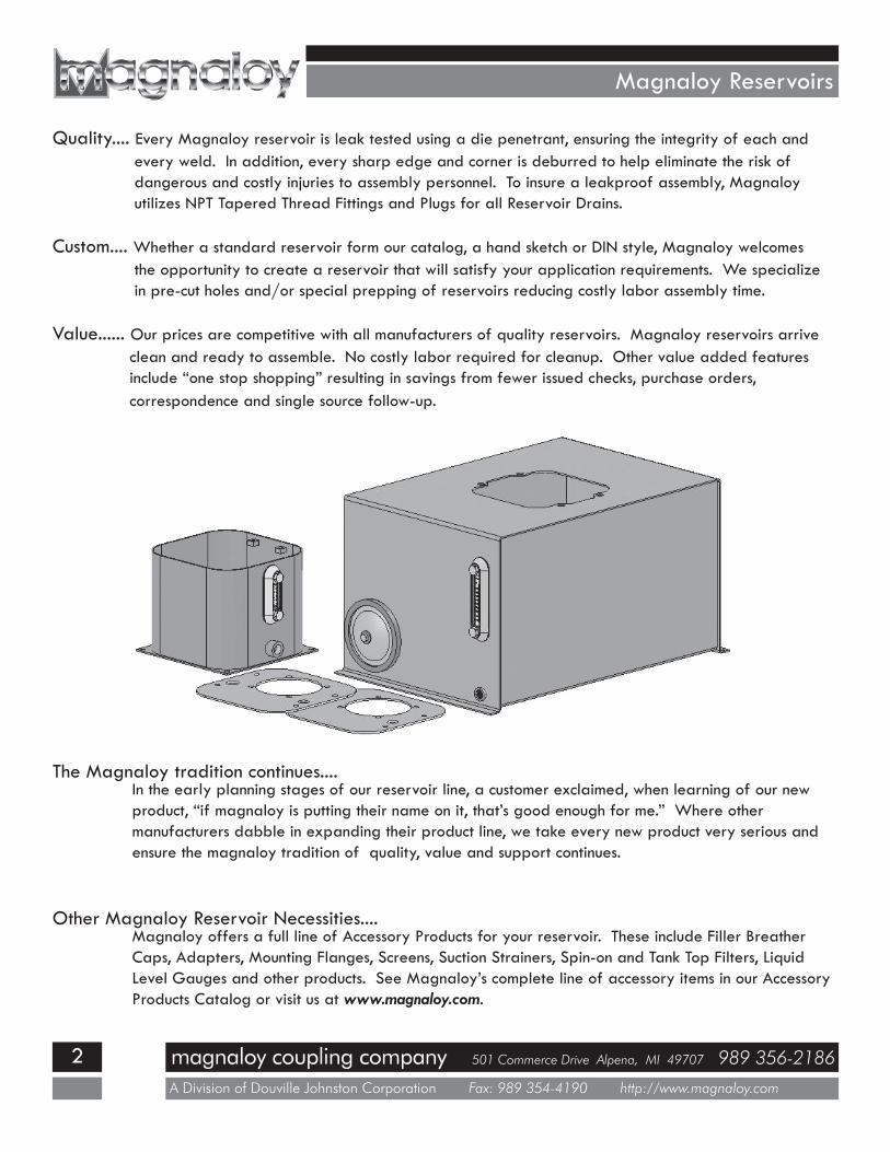
Magnaloy Reservoirs
Quality.... Every Magnaloy reservoir is leak tested using a die penetrant, ensuring the integrity of each andevery weld. In addition, every sharp edge and corner is deburred to help eliminate the risk ofdangerous and costly injuries to assembly personnel. To insure a leakproof assembly, Magnaloyutilizes NPT Tapered Thread Fittings and Plugs for all Reservoir Drains.
Custom.... Whether a standard reservoir form our catalog, a hand sketch or DIN style, Magnaloy welcomesthe opportunity to create a reservoir that will satisfy your application requirements. We specializein pre-cut holes and/or special prepping of reservoirs reducing costly labor assembly time.
Value...... Our prices are competitive with all manufacturers of quality reservoirs. Magnaloy reservoirs arriveclean and ready to assemble. No costly labor required for cleanup. Other value added featuresinclude “one stop shopping” resulting in savings from fewer issued checks, purchase orders,correspondence and single source follow-up.
The Magnaloy tradition continues....In the early planning stages of our reservoir line, a customer exclaimed, when learning of our newproduct, “if magnaloy is putting their name on it, that’s good enough for me.” Where othermanufacturers dabble in expanding their product line, we take every new product very serious andensure the magnaloy tradition of quality, value and support continues.
Other Magnaloy Reservoir Necessities....Magnaloy offers a full line of Accessory Products for your reservoir. These include Filler BreatherCaps, Adapters, Mounting Flanges, Screens, Suction Strainers, Spin-on and Tank Top Filters, LiquidLevel Gauges and other products. See Magnaloy’s complete line of accessory items in our AccessoryProducts Catalog or visit us at www.magnaloy.com.
magnaloy coupling company 501 Commerce Drive Alpena, MI 49707 989 356-2186
A Division of Douville Johnston Corporation Fax: 989 354-4190 http://www.magnaloy.com
3
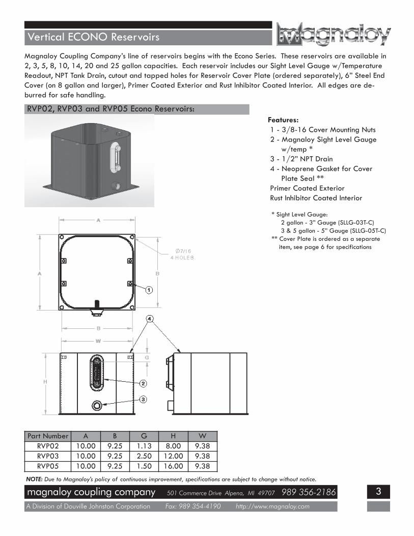
Vertical ECONO ReservoirsMagnaloy Coupling Company’s line of reservoirs begins with the Econo Series. These reservoirs are available in2, 3, 5, 8, 10, 14, 20 and 25 gallon capacities. Each reservoir includes our Sight Level Gauge w/TemperatureReadout, NPT Tank Drain, cutout and tapped holes for Reservoir Cover Plate (ordered separately), 6” Steel EndCover (on 8 gallon and larger), Primer Coated Exterior and Rust Inhibitor Coated Interior. All edges are de-burred for safe handling.
RVP02, RVP03 and RVP05 Econo Reservoirs:Features:1 - 3/8-16 Cover Mounting Nuts2 - Magnaloy Sight Level Gauge
w/temp *3 - 1/2” NPT Drain4 - Neoprene Gasket for Cover
Plate Seal **Primer Coated ExteriorRust Inhibitor Coated Interior
* Sight Level Gauge:2 gallon - 3” Gauge (SLLG-03T-C)3 & 5 gallon - 5” Gauge (SLLG-05T-C)
** Cover Plate is ordered as a separateitem, see page 6 for specifications
Part Number A B G H WRVP02 10.00 9.25 1.13 8.00 9.38RVP03 10.00 9.25 2.50 12.00 9.38RVP05 10.00 9.25 1.50 16.00 9.38
NOTE: Due to Magnaloy’s policy of continuous improvement, specifications are subject to change without notice.

magnaloy coupling company 501 Commerce Drive Alpena, MI 49707 989 356-2186
A Division of Douville Johnston Corporation Fax: 989 354-4190 http://www.magnaloy.com
4
Vertical ECONO ReservoirsRVP08, RVP10 and RVP14 Econo Reservoirs:
Features:1 - 3/8-16 Cover Mounting Nuts2 - Magnaloy 5” Sight Level Gauge w/temp
(SLLG-05T-C)3 - 3/4” NPT Drain4 - Neoprene Gasket for Cover Plate Seal *5 - 6” Steel Clean-out Cover (REC06)Primer Coated ExteriorRust Inhibitor Coated Interior
* Cover Plate is ordered as a separate item, see page 6 forspecifications
Part Number A B C D E F G H W
RVP08 12.00 11.13 14.25 13.38 5.06 1.63 3.13 18.13 12.00
RVP10 15.00 14.13 19.00 18.13 6.25 2.63 2.81 13.94 16.75
RVP14 12.00 11.13 20.25 19.38 6.88 1.63 2.88 20.13 18.00
NOTE: Due to Magnaloy’s policy of continuous improvement, specifications are subject to change without notice.
magnaloy coupling company 501 Commerce Drive Alpena, MI 49707 989 356-2186
A Division of Douville Johnston Corporation Fax: 989 354-4190 http://www.magnaloy.com
5
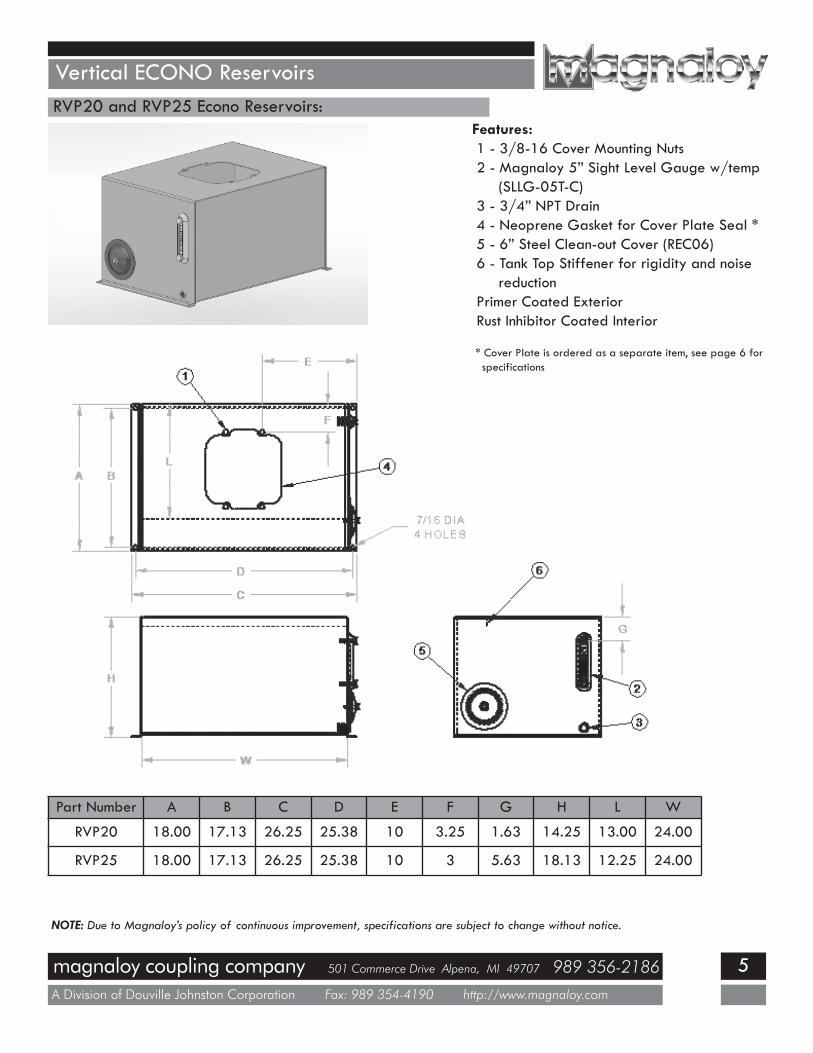
Vertical ECONO ReservoirsRVP20 and RVP25 Econo Reservoirs:
Features:1 - 3/8-16 Cover Mounting Nuts2 - Magnaloy 5” Sight Level Gauge w/temp
(SLLG-05T-C)3 - 3/4” NPT Drain4 - Neoprene Gasket for Cover Plate Seal *5 - 6” Steel Clean-out Cover (REC06)6 - Tank Top Stiffener for rigidity and noise
reductionPrimer Coated ExteriorRust Inhibitor Coated Interior
* Cover Plate is ordered as a separate item, see page 6 forspecifications
Part Number A B C D E F G H L W
RVP20 18.00 17.13 26.25 25.38 10 3.25 1.63 14.25 13.00 24.00
RVP25 18.00 17.13 26.25 25.38 10 3 5.63 18.13 12.25 24.00
NOTE: Due to Magnaloy’s policy of continuous improvement, specifications are subject to change without notice.

magnaloy coupling company 501 Commerce Drive Alpena, MI 49707 989 356-2186
A Division of Douville Johnston Corporation Fax: 989 354-4190 http://www.magnaloy.com
6
Vertical ECONO Reservoirs
RVPT-1, RVPT-2, RVPT-3 and RVPT-4 Cover Plates:Magnaloy offer 4 choices of Cover Plates for the Econo Series of Reservoirs to meet your specific requirements.Each Cover Plate will fit any of the Econo Reservoirs. All Cover Plates are formed from 7 gauge sheet metal.
RVPT-1 Cover Plate RVPT-2 Cover PlateBlank Cover Includes: 1 - Filler Breather Cutout(1/2” NPT)
RVPT-3 Cover Plate RVPT-4 Cover PlateIncludes: 1 - Filler Breather Cutout(1/2” NPT) Includes: 1 - Filler Breather Cutout(1/2” NPT)
2 - 056C Mount Cutout 2 - 056C Mount Cutout3 - 1/2” NPT Connector
Part Number A B C DRVPT-1 10.11 N/A N/A N/ARVPT-2 10.11 .88 3.88 N/ARVPT-3 10.11 .88 3.88 1.41RVPT-4 10.11 .88 3.88 1.41
NOTE: Reservoirs and Cover Plates areordered separately. Order by thespecific part number for the Reservoirand Cover Plate.
NOTE: Due to Magnaloy’s policy of continuous improvement, specifications are subject to change without notice.

magnaloy coupling company 501 Commerce Drive Alpena, MI 49707 989 356-2186
A Division of Douville Johnston Corporation Fax: 989 354-4190 http://www.magnaloy.com
7
Vertical Series Reservoirs
RVSxx-x Series Reservoirs:Size Body Form Bottom Form5 gal 11 ga 11 ga10 gal 11 ga 11 ga20 gal 11 ga 11 ga30 gal 11 ga 11 ga40 gal 11 ga 11 ga
Includes:1- Sight Level Gauge (front mount)
(SLLG-05T-C)2 - 1/2” NPT Tank Drain3 - (4) 3/8-16 Threaded Gussets for
Cover Mounting Bolts4 - “U” Gasket for Top Seal5 - 9/16” Dia. Holes on Bottom Flange
for Tank MountingChoice of Top - ordered separately, seepage 8Primer Coated ExteriorRust Inhibitor Coated Interior
PartNumber
SeriesCapacityGallons
Reservoir Dimensions (Inches)A B C D E F J K
RVS05-1 1 5 14.5 12.5 10 12 0.5 1.25 13.5 10RVS10A-1 1 10 14.5 12.5 19.69 12 0.5 1.25 13.5 10RVS10B-2 2 10 19 16.5 11.75 16 0.75 1.25 17.5 14RVS10-2 2 10 19 16.5 15 16 0.75 1.25 17.5 14RVS20-2 2 20 19 16.5 23.69 16 0.75 1.25 17.5 14RVS20-3 3 20 20.5 18 18 17.5 0.75 1.5 19 15RVS30-2 2 30 19 16.5 35.69 16 0.75 1.25 17.5 14RVS30-3 3 30 20.5 18 26 17.5 0.75 1.5 19 15RVS40-3 3 40 20.5 18 34 17.5 0.75 1.5 19 15
NOTE: Due to Magnaloy’s policy of continuous improvement, specifications are subject to change without notice.
magnaloy coupling company 501 Commerce Drive Alpena, MI 49707 989 356-2186
A Division of Douville Johnston Corporation Fax: 989 354-4190 http://www.magnaloy.com
8
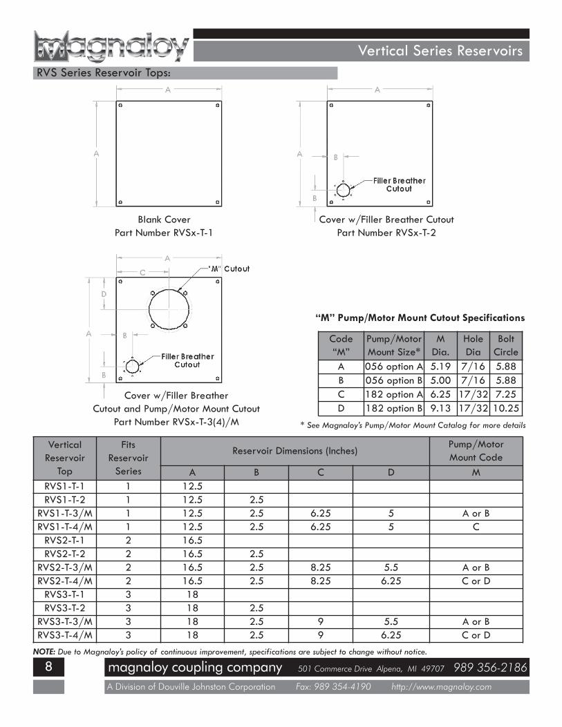
Vertical Series ReservoirsRVS Series Reservoir Tops:
Blank CoverPart Number RVSx-T-1
Cover w/Filler Breather CutoutPart Number RVSx-T-2
Cover w/Filler BreatherCutout and Pump/Motor Mount Cutout
Part Number RVSx-T-3(4)/M
VerticalReservoir
Top
FitsReservoirSeries
Reservoir Dimensions (Inches)Pump/MotorMount Code
A B C D MRVS1-T-1 1 12.5RVS1-T-2 1 12.5 2.5
RVS1-T-3/M 1 12.5 2.5 6.25 5 A or BRVS1-T-4/M 1 12.5 2.5 6.25 5 CRVS2-T-1 2 16.5RVS2-T-2 2 16.5 2.5
RVS2-T-3/M 2 16.5 2.5 8.25 5.5 A or BRVS2-T-4/M 2 16.5 2.5 8.25 6.25 C or DRVS3-T-1 3 18RVS3-T-2 3 18 2.5
RVS3-T-3/M 3 18 2.5 9 5.5 A or BRVS3-T-4/M 3 18 2.5 9 6.25 C or D
Code“M”
Pump/MotorMount Size*
MDia.
HoleDia
BoltCircle
A 056 option A 5.19 7/16 5.88B 056 option B 5.00 7/16 5.88C 182 option A 6.25 17/32 7.25D 182 option B 9.13 17/32 10.25
NOTE: Due to Magnaloy’s policy of continuous improvement, specifications are subject to change without notice.
“M” Pump/Motor Mount Cutout Specifications
* See Magnaloy’s Pump/Motor Mount Catalog for more details

magnaloy coupling company 501 Commerce Drive Alpena, MI 49707 989 356-2186
A Division of Douville Johnston Corporation Fax: 989 354-4190 http://www.magnaloy.com
9
JIC Series ReservoirsRJICxx-FT* JIC Series Reservoirs:
Size Ends Form Top Baffle10 gal 7 ga 11 ga 7 ga 12 ga15 gal 7 ga 11 ga 7 ga 12 ga20 gal 7 ga 11 ga 7 ga 12 ga30 gal 7 ga 11 ga 7 ga 12 ga40 gal 7 ga 11 ga 7 ga 12 ga50 gal 7 ga 11 ga 7 ga 12 ga60 gal 7 ga 11 ga 1/4” 12 ga80 gal 7 ga 11 ga 3/8” 12 ga100 gal 7 ga 11 ga 3/8” 12 ga120 gal 3/8” 11 ga 3/8” 12 ga150 gal 3/8” 11 ga 3/8” 12 ga200 gal 3/8” 7 ga 3/8” 12 ga
Includes:1 - Sight Level Gauge (front mount)
(SLLG-05T-C)2 - End Cover w/3/4” NPT Drain
End Cover w/out Drain (opposite end)3 - Sloped Bottom4 - Filler Breather Cap and Riser
(FB-H008)5 - Baffle w/Circulation CutoutPrimer Coated ExteriorRust Inhibitor Coated Interior
PartNumber
CapacityGallons
Reservoir Dimensions (Inches) EndCoverA B C D E
RJIC010-FT 10 22 18 19 18.25 16.5 12”RJIC015-FT 15 26 18 19 22.25 16.5 12”RJIC020-FT 20 30 18 19 26.25 16.5 12”RJIC030-FT 30 36 24 19.38 32.25 22.5 12”RJIC040-FT 40 36 24 21 32.25 22.5 12”RJIC050-FT 50 36 24 23 32.25 22.5 16”RJIC060-FT 60 48 27 20.69 44.25 25.5 16”RJIC080-FT 80 60 27 21.5 56.25 25.5 16”RJIC100-FT 100 60 27 23.5 56.25 25.5 16”RJIC120-FT 120 60 30 27 56.25 28.5 16”RJIC150-FT 150 60 30 31 56.25 28.5 16”RJIC200-FT 200 72 36 29.38 68.25 34.5 18”
NOTE: Couplings, both SAE & NPT can be installed per your specifications* Also available with Removable Top (substitute RT for FT) and Removable Baffle (substitute RB for FT)NOTE: Due to Magnaloy’s policy of continuous improvement, specifications are subject to change without notice.

magnaloy coupling company 501 Commerce Drive Alpena, MI 49707 989 356-2186
A Division of Douville Johnston Corporation Fax: 989 354-4190 http://www.magnaloy.com
10
L Series ReservoirsRLCxx-FT Series Reservoirs:
Size Form Top Bottom Baffle10 gal 7 ga 1/4” 7 ga 11 ga20 gal 7 ga 1/4” 7 ga 11 ga30 gal 7 ga 1/4” 7 ga 11 ga45 gal 7 ga 1/4” 7 ga 11 ga60 gal 7 ga 1/4” 7 ga 11 ga80 gal 7 ga 1/4” 3/8” 11 ga100 gal 7 ga 1/4” 3/8” 11 ga120 gal 7 ga 1/4” 3/8” 11 ga150 gal 7 ga 1/4” 3/8” 11 ga200 gal 7 ga 1/4” 3/8” 11 ga
Includes:1- Sight Level Gauge (front mount)
(SLLG-05T-C)2 - Filler Breather Cap and Riser
(FB-H008)3 - Fixed Top (Welded)4 - Clean-out Cover on Back Side5 - Baffles w/Circulation Cutout6 - 3/4” NPT Tank Drain7 - Lifting Holes in Channel Ends8 - 9/16 Dia Holes, 2 per Channel9 - Optional Porch Sizes-consult factory
10 - Return Line Connection - “O” NPT11 - Bottom StiffenerPrimer Coated ExteriorRust Inhibitor Coated Interior
PartNumber
CapacityGallons
Reservoir Dimensions (Inches) Return Connections CoverSizeA B C D E J K M N O
RLC010-FT 10 24 22 26.56 6.5 15.44 22.25 18 4.5 3.25 1/2” 12RLC020-FT 20 36 27 26.56 7.5 19.44 34.25 23 5.5 3.75 1” 12RLC030-FT 30 36 30 28.56 10.5 19.44 34.25 26 7.5 5.25 1 1/2” 12RLC045-FT 45 42 36 29.56 12.5 23.44 40.25 32 9.5 6.25 1 1/2” 12RLC060-FT 60 42 36 29.56 16.5 19.44 40.25 32 13.5 8.25 1 1/2” 12RLC080-FT 80 48 42 30.56 18.5 23.5 46.25 38 15.5 9.25 1 1/2” 16RLC100-FT 100 50 47 31.56 21.5 25.5 48.25 43 18.5 10.75 2” 16RLC120-FT 120 52 50 32.56 22.5 27.5 50.25 46 19.5 11.25 2” 16RLC150-FT 150 60 50 33.56 22.5 27.5 58.25 46 19.5 11.25 2” 16RLC200-FT 200 60 57 40.56 25.5 31.5 58.25 53 22.5 12.75 2” 16NOTE: Due to Magnaloy’s policy of continuous improvement, specifications are subject to change without notice.
magnaloy coupling company 501 Commerce Drive Alpena, MI 49707 989 356-2186
A Division of Douville Johnston Corporation Fax: 989 354-4190 http://www.magnaloy.com
11
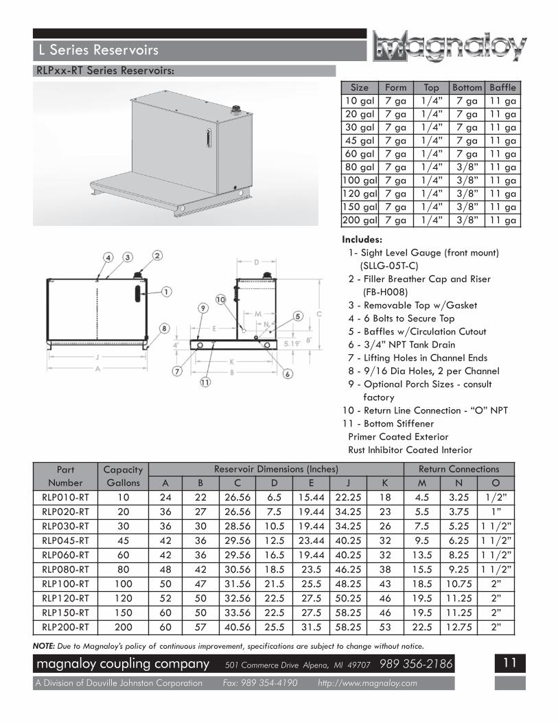
L Series ReservoirsRLPxx-RT Series Reservoirs:
Size Form Top Bottom Baffle10 gal 7 ga 1/4” 7 ga 11 ga20 gal 7 ga 1/4” 7 ga 11 ga30 gal 7 ga 1/4” 7 ga 11 ga45 gal 7 ga 1/4” 7 ga 11 ga60 gal 7 ga 1/4” 7 ga 11 ga80 gal 7 ga 1/4” 3/8” 11 ga100 gal 7 ga 1/4” 3/8” 11 ga120 gal 7 ga 1/4” 3/8” 11 ga150 gal 7 ga 1/4” 3/8” 11 ga200 gal 7 ga 1/4” 3/8” 11 ga
Includes:1- Sight Level Gauge (front mount)
(SLLG-05T-C)2 - Filler Breather Cap and Riser
(FB-H008)3 - Removable Top w/Gasket4 - 6 Bolts to Secure Top5 - Baffles w/Circulation Cutout6 - 3/4” NPT Tank Drain7 - Lifting Holes in Channel Ends8 - 9/16 Dia Holes, 2 per Channel9 - Optional Porch Sizes - consult
factory10 - Return Line Connection - “O” NPT11 - Bottom StiffenerPrimer Coated ExteriorRust Inhibitor Coated Interior
PartNumber
CapacityGallons
Reservoir Dimensions (Inches) Return ConnectionsA B C D E J K M N O
RLP010-RT 10 24 22 26.56 6.5 15.44 22.25 18 4.5 3.25 1/2”RLP020-RT 20 36 27 26.56 7.5 19.44 34.25 23 5.5 3.75 1”RLP030-RT 30 36 30 28.56 10.5 19.44 34.25 26 7.5 5.25 1 1/2”RLP045-RT 45 42 36 29.56 12.5 23.44 40.25 32 9.5 6.25 1 1/2”RLP060-RT 60 42 36 29.56 16.5 19.44 40.25 32 13.5 8.25 1 1/2”RLP080-RT 80 48 42 30.56 18.5 23.5 46.25 38 15.5 9.25 1 1/2”RLP100-RT 100 50 47 31.56 21.5 25.5 48.25 43 18.5 10.75 2”RLP120-RT 120 52 50 32.56 22.5 27.5 50.25 46 19.5 11.25 2”RLP150-RT 150 60 50 33.56 22.5 27.5 58.25 46 19.5 11.25 2”RLP200-RT 200 60 57 40.56 25.5 31.5 58.25 53 22.5 12.75 2”
NOTE: Due to Magnaloy’s policy of continuous improvement, specifications are subject to change without notice.
magnaloy coupling company 501 Commerce Drive Alpena, MI 49707 989 356-2186
A Division of Douville Johnston Corporation Fax: 989 354-4190 http://www.magnaloy.com
12
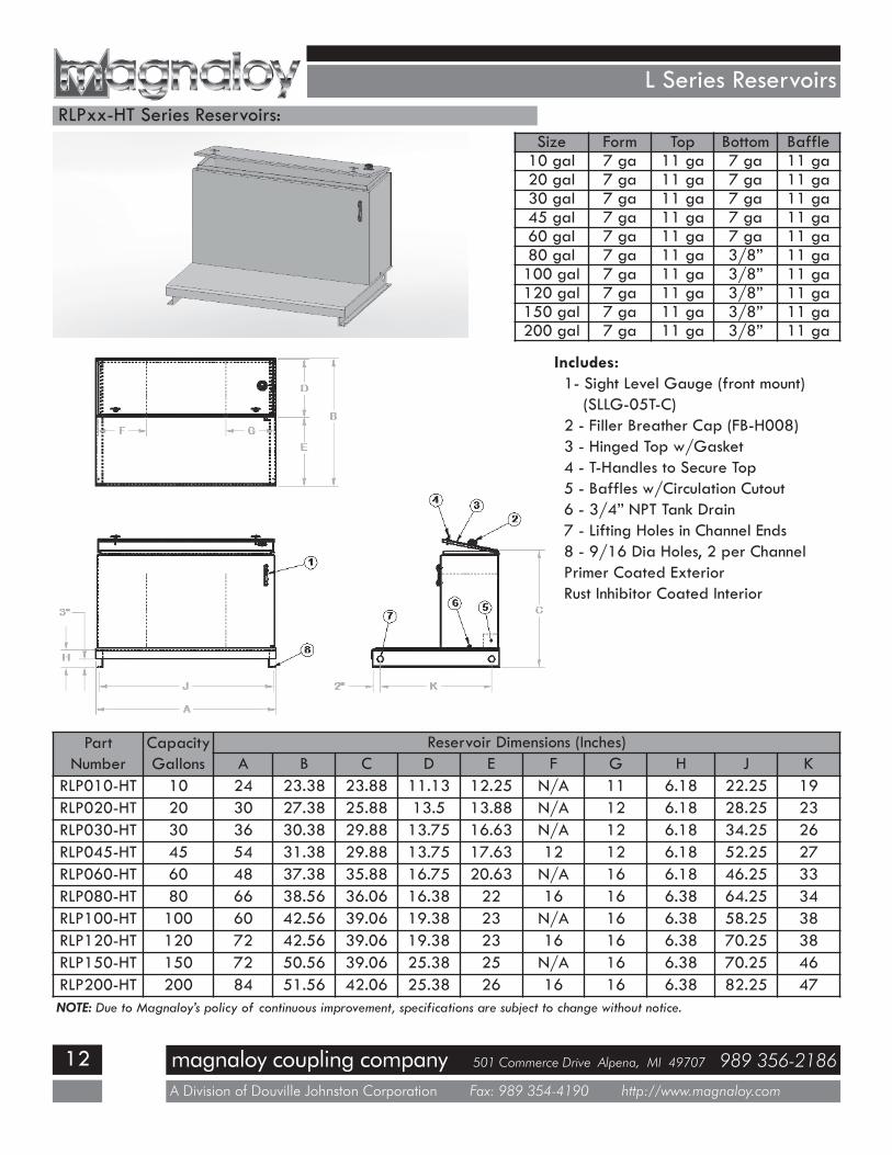
L Series ReservoirsRLPxx-HT Series Reservoirs:
Size Form Top Bottom Baffle10 gal 7 ga 11 ga 7 ga 11 ga20 gal 7 ga 11 ga 7 ga 11 ga30 gal 7 ga 11 ga 7 ga 11 ga45 gal 7 ga 11 ga 7 ga 11 ga60 gal 7 ga 11 ga 7 ga 11 ga80 gal 7 ga 11 ga 3/8” 11 ga100 gal 7 ga 11 ga 3/8” 11 ga120 gal 7 ga 11 ga 3/8” 11 ga150 gal 7 ga 11 ga 3/8” 11 ga200 gal 7 ga 11 ga 3/8” 11 ga
Includes:1- Sight Level Gauge (front mount)
(SLLG-05T-C)2 - Filler Breather Cap (FB-H008)3 - Hinged Top w/Gasket4 - T-Handles to Secure Top5 - Baffles w/Circulation Cutout6 - 3/4” NPT Tank Drain7 - Lifting Holes in Channel Ends8 - 9/16 Dia Holes, 2 per ChannelPrimer Coated ExteriorRust Inhibitor Coated Interior
PartNumber
CapacityGallons
Reservoir Dimensions (Inches)A B C D E F G H J K
RLP010-HT 10 24 23.38 23.88 11.13 12.25 N/A 11 6.18 22.25 19RLP020-HT 20 30 27.38 25.88 13.5 13.88 N/A 12 6.18 28.25 23RLP030-HT 30 36 30.38 29.88 13.75 16.63 N/A 12 6.18 34.25 26RLP045-HT 45 54 31.38 29.88 13.75 17.63 12 12 6.18 52.25 27RLP060-HT 60 48 37.38 35.88 16.75 20.63 N/A 16 6.18 46.25 33RLP080-HT 80 66 38.56 36.06 16.38 22 16 16 6.38 64.25 34RLP100-HT 100 60 42.56 39.06 19.38 23 N/A 16 6.38 58.25 38RLP120-HT 120 72 42.56 39.06 19.38 23 16 16 6.38 70.25 38RLP150-HT 150 72 50.56 39.06 25.38 25 N/A 16 6.38 70.25 46RLP200-HT 200 84 51.56 42.06 25.38 26 16 16 6.38 82.25 47NOTE: Due to Magnaloy’s policy of continuous improvement, specifications are subject to change without notice.

magnaloy coupling company 501 Commerce Drive Alpena, MI 49707 989 356-2186
A Division of Douville Johnston Corporation Fax: 989 354-4190 http://www.magnaloy.com
13
L Series ReservoirsRLPxx-PHT Series Reservoirs:
Includes:1- Sight Level Gauge (front mount)
(SLLG-05T-C)2 - Filler Breather Cap (FB-H008)3 - Partial Hinged Top w/Gasket4 - T-Handles to Secure Top5 - Baffles w/Circulation Cutout6 - 3/4” NPT Tank Drain7 - Lifting Holes in Channel Ends8 - 9/16 Dia Holes, 2 per Channel9 - Upper Porch for filter mountingPrimer Coated ExteriorRust Inhibitor Coated Interior
PartNumber
CapacityGallons
Reservoir Dimensions (Inches)A B C D E F G H J K P
RLP080-PHT 80 60 38.56 36.06 13.38 25 16 16 6.38 58.25 34 12RLP100-PHT 100 60 42.56 36.06 16.38 26 16 16 6.38 58.25 38 12RLP120-PHT 120 72 42.56 36.06 16.38 26 16 16 6.38 70.25 38 12RLP150-PHT 150 72 50.56 39.06 18.38 32 16 16 6.38 70.25 46 12RLP200-PHT 200 84 51.56 42.06 18.38 33 24 16 6.38 82.25 47 16
NOTE: Due to Magnaloy’s policy of continuous improvement, specifications are subject to change without notice.
Size Form Top Lid Bottom Baffle80 gal 7 ga 7 ga 11 ga 3/8” 11 ga100 gal 7 ga 7 ga 11 ga 3/8” 11 ga120 gal 7 ga 7 ga 11 ga 3/8” 11 ga150 gal 7 ga 7 ga 11 ga 3/8” 11 ga200 gal 7 ga 7 ga 11 ga 3/8” 11 ga
magnaloy coupling company 501 Commerce Drive Alpena, MI 49707 989 356-2186
A Division of Douville Johnston Corporation Fax: 989 354-4190 http://www.magnaloy.com
14
Horizontal Series Reservoirs
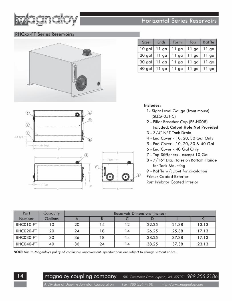
RHCxx-FT Series Reservoirs:
Includes:1- Sight Level Gauge (front mount)
(SLLG-05T-C)2 - Filler Breather Cap (FB-H008)
Included, Cutout Hole Not Provided3 - 3/4” NPT Tank Drain4 - End Cover - 10, 20, 30 Gal Only5 - End Cover - 10, 20, 30 & 40 Gal6 - End Cover - 40 Gal Only7 - Top Stiffeners - except 10 Gal8 - 7/16” Dia. Holes on Bottom Flange
for Tank Mounting9 - Baffle w/cutout for circulationPrimer Coated ExteriorRust Inhibitor Coated Interior
PartNumber
CapacityGallons
Reservoir Dimensions (Inches)A B C D J K
RHC010-FT 10 20 14 12 22.25 21.38 13.13RHC020-FT 20 24 18 14 26.25 25.38 17.13RHC030-FT 30 36 18 14 38.25 37.38 17.13RHC040-FT 40 36 24 14 38.25 37.38 23.13
NOTE: Due to Magnaloy’s policy of continuous improvement, specifications are subject to change without notice.
Size Ends Form Top Baffle10 gal 11 ga 11 ga 11 ga 11 ga20 gal 11 ga 11 ga 11 ga 11 ga30 gal 11 ga 11 ga 11 ga 11 ga40 gal 11 ga 11 ga 11 ga 11 ga

magnaloy coupling company 501 Commerce Drive Alpena, MI 49707 989 356-2186
A Division of Douville Johnston Corporation Fax: 989 354-4190 http://www.magnaloy.com
15
Horizontal Series Reservoirs
RHPxx-RT Series Reservoirs:
Includes:1- Sight Level Gauge (front mount)
(SLLG-05T-C)2 - Filler Breather Cap (FB-H008)
Included, Cutout Hole Not Provided3 - Neoprene Foam Gasket Top Seal4 - 3/4” NPT Tank Drain5 - 6 Bolts to secure Top (1/4”-20)6 - 1/2” Dia. Holes on Bottom Flange
for Tank MountingPrimer Coated ExteriorRust Inhibitor Coated Interior
Size Ends Form Top Baffle10 gal 11 ga 11 ga 1/4” 11 ga20 gal 11 ga 11 ga 1/4” 11 ga30 gal 11 ga 11 ga 1/4” 11 ga40 gal 11 ga 11 ga 1/4” 11 ga
PartNumber
CapacityGallons
Reservoir Dimensions (Inches)
A B C D E J K
RHP010-RT 10 24 16 9.5 21.75 12.75 25.25 15
RHP020-RT 20 24 16 15.5 21.75 12.75 25.25 15
RHP030-RT 30 24 16 21.5 21.75 12.75 25.25 15
RHP040-RT 40 24 16 27.5 21.75 12.75 25.25 15
NOTE: Due to Magnaloy’s policy of continuous improvement, specifications are subject to change without notice.
magnaloy coupling company 501 Commerce Drive Alpena, MI 49707 989 356-2186
A Division of Douville Johnston Corporation Fax: 989 354-4190 http://www.magnaloy.com
16
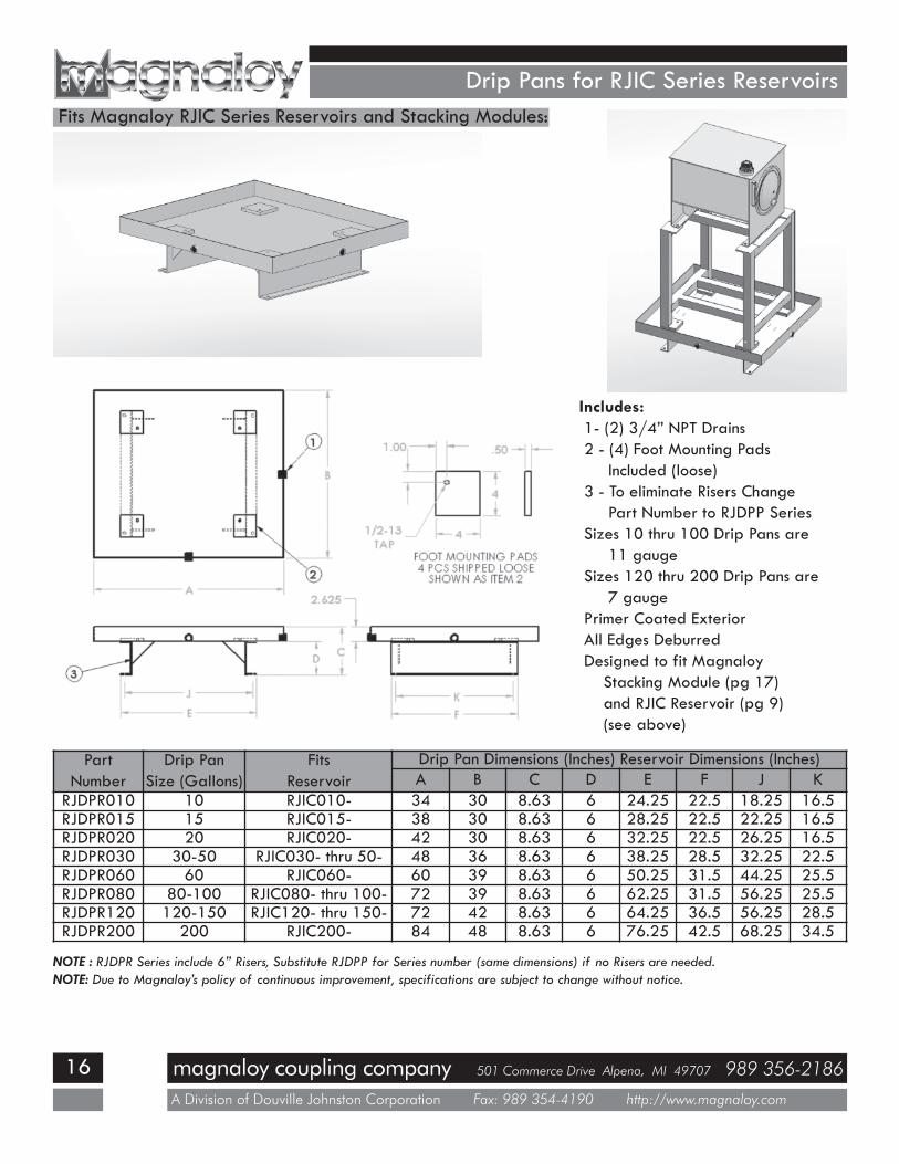
Drip Pans for RJIC Series ReservoirsFits Magnaloy RJIC Series Reservoirs and Stacking Modules:
Includes:1- (2) 3/4” NPT Drains2 - (4) Foot Mounting Pads
Included (loose)3 - To eliminate Risers Change
Part Number to RJDPP SeriesSizes 10 thru 100 Drip Pans are
11 gaugeSizes 120 thru 200 Drip Pans are
7 gaugePrimer Coated ExteriorAll Edges DeburredDesigned to fit Magnaloy
Stacking Module (pg 17)and RJIC Reservoir (pg 9)(see above)
PartNumber
Drip PanSize (Gallons)
FitsReservoir
Drip Pan Dimensions (Inches) Reservoir Dimensions (Inches)A B C D E F J K
RJDPR010 10 RJIC010- 34 30 8.63 6 24.25 22.5 18.25 16.5RJDPR015 15 RJIC015- 38 30 8.63 6 28.25 22.5 22.25 16.5RJDPR020 20 RJIC020- 42 30 8.63 6 32.25 22.5 26.25 16.5RJDPR030 30-50 RJIC030- thru 50- 48 36 8.63 6 38.25 28.5 32.25 22.5RJDPR060 60 RJIC060- 60 39 8.63 6 50.25 31.5 44.25 25.5RJDPR080 80-100 RJIC080- thru 100- 72 39 8.63 6 62.25 31.5 56.25 25.5RJDPR120 120-150 RJIC120- thru 150- 72 42 8.63 6 64.25 36.5 56.25 28.5RJDPR200 200 RJIC200- 84 48 8.63 6 76.25 42.5 68.25 34.5
NOTE : RJDPR Series include 6” Risers, Substitute RJDPP for Series number (same dimensions) if no Risers are needed.NOTE: Due to Magnaloy’s policy of continuous improvement, specifications are subject to change without notice.
magnaloy coupling company 501 Commerce Drive Alpena, MI 49707 989 356-2186
A Division of Douville Johnston Corporation Fax: 989 354-4190 http://www.magnaloy.com
17
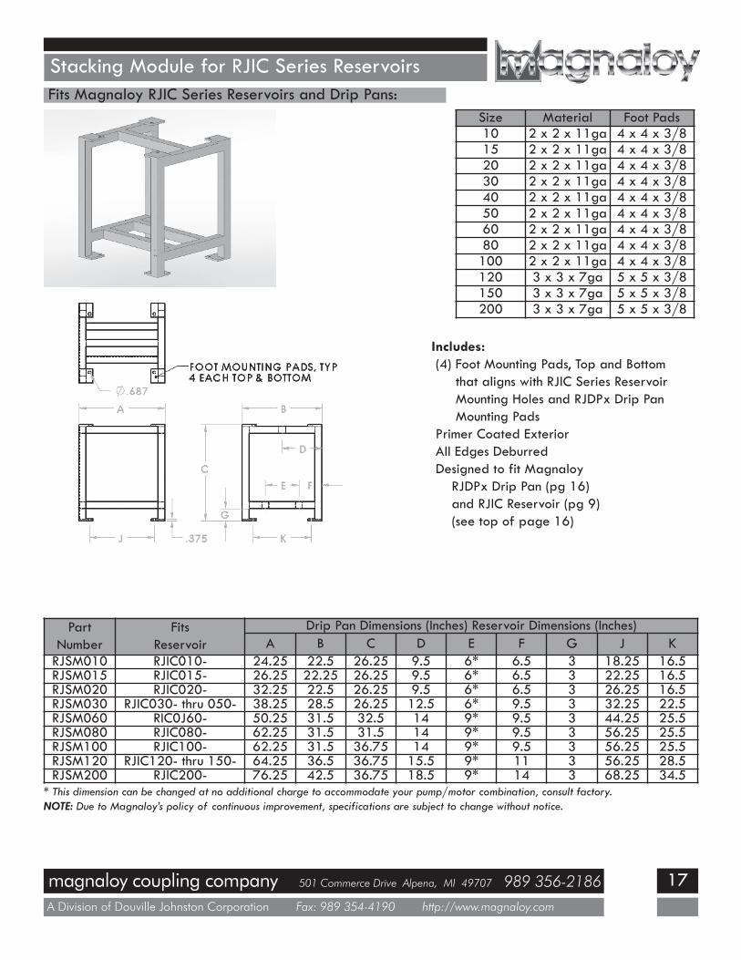
Stacking Module for RJIC Series ReservoirsFits Magnaloy RJIC Series Reservoirs and Drip Pans:
Size Material Foot Pads10 2 x 2 x 11ga 4 x 4 x 3/815 2 x 2 x 11ga 4 x 4 x 3/820 2 x 2 x 11ga 4 x 4 x 3/830 2 x 2 x 11ga 4 x 4 x 3/840 2 x 2 x 11ga 4 x 4 x 3/850 2 x 2 x 11ga 4 x 4 x 3/860 2 x 2 x 11ga 4 x 4 x 3/880 2 x 2 x 11ga 4 x 4 x 3/8100 2 x 2 x 11ga 4 x 4 x 3/8120 3 x 3 x 7ga 5 x 5 x 3/8150 3 x 3 x 7ga 5 x 5 x 3/8200 3 x 3 x 7ga 5 x 5 x 3/8
PartNumber
FitsReservoir
Drip Pan Dimensions (Inches) Reservoir Dimensions (Inches)A B C D E F G J K
RJSM010 RJIC010- 24.25 22.5 26.25 9.5 6* 6.5 3 18.25 16.5RJSM015 RJIC015- 26.25 22.25 26.25 9.5 6* 6.5 3 22.25 16.5RJSM020 RJIC020- 32.25 22.5 26.25 9.5 6* 6.5 3 26.25 16.5RJSM030 RJIC030- thru 050- 38.25 28.5 26.25 12.5 6* 9.5 3 32.25 22.5RJSM060 RIC0J60- 50.25 31.5 32.5 14 9* 9.5 3 44.25 25.5RJSM080 RJIC080- 62.25 31.5 31.5 14 9* 9.5 3 56.25 25.5RJSM100 RJIC100- 62.25 31.5 36.75 14 9* 9.5 3 56.25 25.5RJSM120 RJIC120- thru 150- 64.25 36.5 36.75 15.5 9* 11 3 56.25 28.5RJSM200 RJIC200- 76.25 42.5 36.75 18.5 9* 14 3 68.25 34.5
* This dimension can be changed at no additional charge to accommodate your pump/motor combination, consult factory.NOTE: Due to Magnaloy’s policy of continuous improvement, specifications are subject to change without notice.
Includes:(4) Foot Mounting Pads, Top and Bottom
that aligns with RJIC Series ReservoirMounting Holes and RJDPx Drip PanMounting Pads
Primer Coated ExteriorAll Edges DeburredDesigned to fit Magnaloy
RJDPx Drip Pan (pg 16)and RJIC Reservoir (pg 9)(see top of page 16)

magnaloy coupling company 501 Commerce Drive Alpena, MI 49707 989 356-2186
A Division of Douville Johnston Corporation Fax: 989 354-4190 http://www.magnaloy.com
18
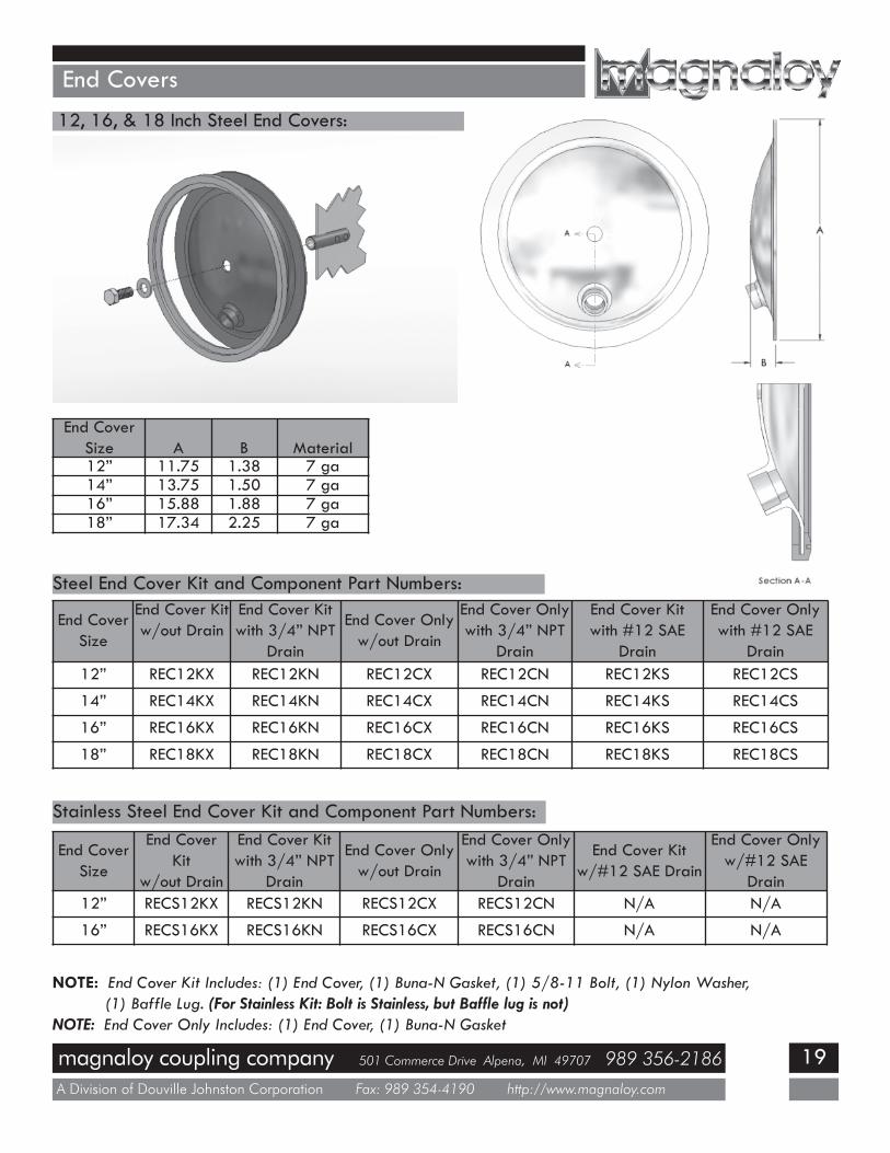
End Covers
End CoverSize
O.D. Height Material
REC06 5.38 .75 7 ga.
6 Inch Steel End Cover:
End CoverSize
End CoverAssembly
End CoverFront Cover
End CoverBack Plate
End CoverGasket
End CoverNylon Washer
End CoverBolt
6” REC06K REC06C REC06B REC06G REC06W REC06F
End Cover Assembly and Component Part Numbers:
NOTE: End Cover Assembly Includes - (1) Front Plate, (1) Back Plate, (1) 3/8-16 x 1.25” Bolt, (1) Nylon CrushWasher, (1) Buna-N Cover Gasket.
NOTE: 4.625” Diameter Hole in the Reservoir is required for installation.
magnaloy coupling company 501 Commerce Drive Alpena, MI 49707 989 356-2186
A Division of Douville Johnston Corporation Fax: 989 354-4190 http://www.magnaloy.com
19
End Covers
12, 16, & 18 Inch Steel End Covers:
Steel End Cover Kit and Component Part Numbers:
End CoverSize
End Cover Kitw/out Drain
End Cover Kitwith 3/4” NPT
Drain
End Cover Onlyw/out Drain
End Cover Onlywith 3/4” NPT
Drain
End Cover Kitwith #12 SAE
Drain
End Cover Onlywith #12 SAE
Drain12” REC12KX REC12KN REC12CX REC12CN REC12KS REC12CS
14” REC14KX REC14KN REC14CX REC14CN REC14KS REC14CS
16” REC16KX REC16KN REC16CX REC16CN REC16KS REC16CS
18” REC18KX REC18KN REC18CX REC18CN REC18KS REC18CS
End CoverSize
End CoverKit
w/out Drain
End Cover Kitwith 3/4” NPT
Drain
End Cover Onlyw/out Drain
End Cover Onlywith 3/4” NPT
Drain
End Cover Kitw/#12 SAE Drain
End Cover Onlyw/#12 SAE
Drain12” RECS12KX RECS12KN RECS12CX RECS12CN N/A N/A
16” RECS16KX RECS16KN RECS16CX RECS16CN N/A N/A
NOTE: End Cover Kit Includes: (1) End Cover, (1) Buna-N Gasket, (1) 5/8-11 Bolt, (1) Nylon Washer,(1) Baffle Lug. (For Stainless Kit: Bolt is Stainless, but Baffle lug is not)
NOTE: End Cover Only Includes: (1) End Cover, (1) Buna-N Gasket
Stainless Steel End Cover Kit and Component Part Numbers:
End CoverSize A B Material12” 11.75 1.38 7 ga14” 13.75 1.50 7 ga16” 15.88 1.88 7 ga18” 17.34 2.25 7 ga
magnaloy coupling company 501 Commerce Drive Alpena, MI 49707 989 356-2186
A Division of Douville Johnston Corporation Fax: 989 354-4190 http://www.magnaloy.com
20
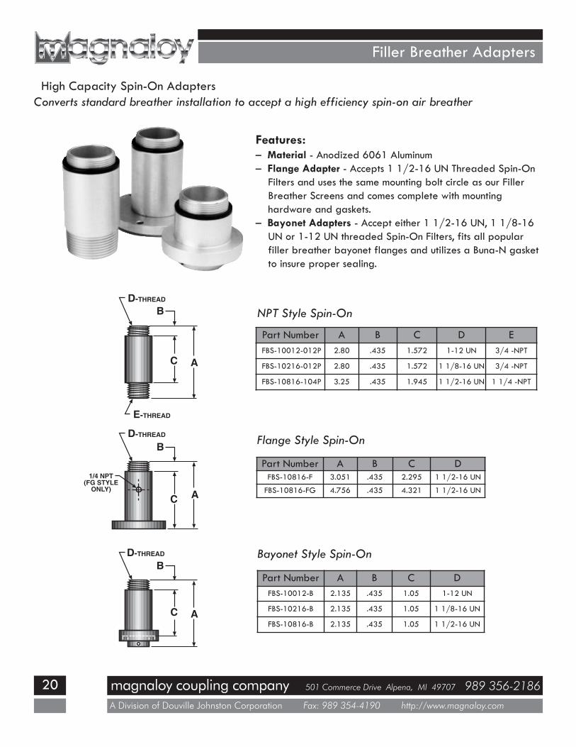
Filler Breather Adapters
High Capacity Spin-On AdaptersConverts standard breather installation to accept a high efficiency spin-on air breather
Features:– Material - Anodized 6061 Aluminum– Flange Adapter - Accepts 1 1/2-16 UN Threaded Spin-On
Filters and uses the same mounting bolt circle as our FillerBreather Screens and comes complete with mountinghardware and gaskets.
– Bayonet Adapters - Accept either 1 1/2-16 UN, 1 1/8-16UN or 1-12 UN threaded Spin-On Filters, fits all popularfiller breather bayonet flanges and utilizes a Buna-N gasketto insure proper sealing.
Part Number A B C D EFBS-10012-012P 2.80 .435 1.572 1-12 UN 3/4 -NPT
FBS-10216-012P 2.80 .435 1.572 1 1/8-16 UN 3/4 -NPT
FBS-10816-104P 3.25 .435 1.945 1 1/2-16 UN 1 1/4 -NPT
NPT Style Spin-On
Flange Style Spin-On
Part Number A B C DFBS-10816-F 3.051 .435 2.295 1 1/2-16 UN
FBS-10816-FG 4.756 .435 4.321 1 1/2-16 UN
Bayonet Style Spin-On
Part Number A B C DFBS-10012-B 2.135 .435 1.05 1-12 UN
FBS-10216-B 2.135 .435 1.05 1 1/8-16 UN
FBS-10816-B 2.135 .435 1.05 1 1/2-16 UN
D-THREAD
D-THREAD
D-THREAD
A
B
C
E-THREAD
C
C
B
B
A
A
1/4 NPT(FG STYLE
ONLY)
magnaloy coupling company 501 Commerce Drive Alpena, MI 49707 989 356-2186
A Division of Douville Johnston Corporation Fax: 989 354-4190 http://www.magnaloy.com
21
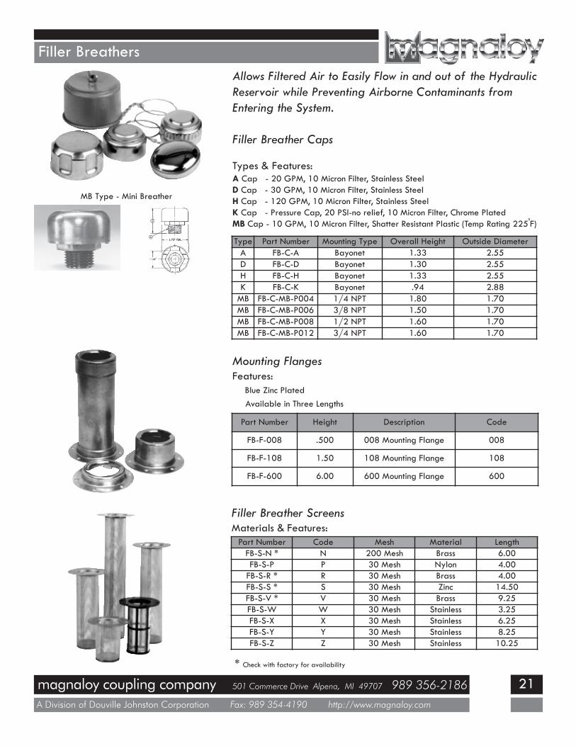
Filler BreathersAllows Filtered Air to Easily Flow in and out of the HydraulicReservoir while Preventing Airborne Contaminants fromEntering the System.
Filler Breather Caps
Types & Features:A Cap - 20 GPM, 10 Micron Filter, Stainless SteelD Cap - 30 GPM, 10 Micron Filter, Stainless SteelH Cap - 120 GPM, 10 Micron Filter, Stainless SteelK Cap - Pressure Cap, 20 PSI-no relief, 10 Micron Filter, Chrome PlatedMB Cap - 10 GPM, 10 Micron Filter, Shatter Resistant Plastic (Temp Rating 225
oF)
Mounting FlangesFeatures:
Blue Zinc PlatedAvailable in Three Lengths
Type Part Number Mounting Type Overall Height Outside DiameterA FB-C-A Bayonet 1.33 2.55D FB-C-D Bayonet 1.30 2.55H FB-C-H Bayonet 1.33 2.55K FB-C-K Bayonet .94 2.88MB FB-C-MB-P004 1/4 NPT 1.80 1.70MB FB-C-MB-P006 3/8 NPT 1.50 1.70MB FB-C-MB-P008 1/2 NPT 1.60 1.70MB FB-C-MB-P012 3/4 NPT 1.60 1.70
Part Number Height Description Code
FB-F-008 .500 008 Mounting Flange 008
FB-F-108 1.50 108 Mounting Flange 108
FB-F-600 6.00 600 Mounting Flange 600
MB Type - Mini Breather
Filler Breather ScreensMaterials & Features:
* Check with factory for availability
Part Number Code Mesh Material LengthFB-S-N * N 200 Mesh Brass 6.00FB-S-P P 30 Mesh Nylon 4.00FB-S-R * R 30 Mesh Brass 4.00FB-S-S * S 30 Mesh Zinc 14.50FB-S-V * V 30 Mesh Brass 9.25FB-S-W W 30 Mesh Stainless 3.25FB-S-X X 30 Mesh Stainless 6.25FB-S-Y Y 30 Mesh Stainless 8.25FB-S-Z Z 30 Mesh Stainless 10.25
magnaloy coupling company 501 Commerce Drive Alpena, MI 49707 989 356-2186
A Division of Douville Johnston Corporation Fax: 989 354-4190 http://www.magnaloy.com
22
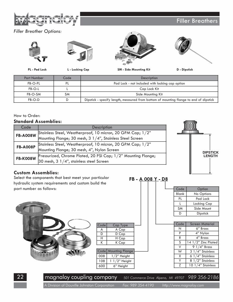
Filler BreathersFiller Breather Options:
PL - Pad Lock L - Locking Cap SM - Side Mounting Kit D - Dipstick
Part Number Code DescriptionFB-O-PL PL Pad Lock - not included with locking cap optionFB-O-L L Cap Lock Kit
FB-O-SM SM Side Mounting KitFB-O-D D Dipstick - specify length, measured from bottom of mounting flange to end of dipstick
How to Order:Standard Assemblies:
Custom Assemblies:FB - A 008 Y - D8
Code OptionBlank No OptionsPL Pad LockL Locking Cap
SM Side MountD Dipstick
Code Screen MaterialN 6” BrassP 4” NylonR 4” BrassS 14 1/2” Zinc PlatedV 9 1/4” BrassW 3 1/4” StainlessX 6 1/4” StainlessY 8 1/2” StainlessZ 10 1/4” Stainless
Code Cap TypeA A CapD D CapH H CapK K Cap
Code Mounting Flange008 1/2” Height108 1 1/2” Height600 6” Height
Select the components that best meet your particularhydraulic system requirements and custom build thepart number as follows:
Code Description
FB-A008WStainless Steel, Weatherproof, 10 micron, 20 GPM Cap; 1/2”Mounting Flange; 30 mesh, 3 1/4”, Stainless Steel Screen
FB-A008PStainless Steel, Weatherproof, 10 micron, 20 GPM Cap; 1/2”Mounting Flange; 30 mesh, 4”, Nylon Screen
FB-K008WPressurized, Chrome Plated, 20 PSI Cap; 1/2” Mounting Flange;30 mesh, 3 1/4”, stainless steel Screen
DIPSTICKLENGTH

magnaloy coupling company 501 Commerce Drive Alpena, MI 49707 989 356-2186
A Division of Douville Johnston Corporation Fax: 989 354-4190 http://www.magnaloy.com
23
Reservoir FlangesPremium Line Suction and Return Line Flanges - heavy duty, positive sealing Suction and Return Line Flanges
Features:- Positive Urethane Seal - protects against particulate andliquid contamination.
- Mounting Hardware - required screws, bolts, washersand gaskets are included.
- Available in Many Popular Tube and Pipe Sizes -1/2” thru 2” Pipe and Tube.
- Large Suction Line Flange Plate - allows easy access forsuction line strainer installation and maintenance.
- Rigid/Heavy Duty Zinc Plated Die Cast Flange - will notdeflect or distort, provides sealing forces to urethane seal.
Pipe Sizes: from 1/2” to 2”Return Line Flange: Suction Line Flange:
Part NumberNominalPipe Size
Pipe ODX
ClearanceHole Dia.
YRLF-008P 1/2” 0.84 1.00RLF-012P 3/4” 1.05 1.19RLF-100P 1” 1.32 1.44RLF-104P 1 1/4” 1.66 1.81RLF-108P 1 1/2” 1.90 2.06RLF-200P 2” 2.38 2.50
Part NumberNominalPipeSize
A B C DPipeODE
ClearanceHole Dia.
FSLF-008P 1/2” 5.50 4.25 2.12 5.25 0.84 4.25SLF-012P 3/4” 5.50 4.25 2.12 5.25 1.05 4.25SLF-100P 1” 5.50 4.25 2.12 5.25 1.32 4.25SLF-104P 1 1/4” 5.50 4.25 2.12 5.25 1.66 4.25SLF-108P 1 1/2” 7.50 6.25 3.12 7.25 1.90 6.25SLF-200P 2” 7.50 6.25 3.12 7.25 2.38 6.25
Tube Sizes: from 1/2” to 2”Return Line Flange: Suction Line Flange:
Part NumberNominalTube Size
Tube ODX
ClearanceHole Dia.
YRLF-008T 1/2” 0.50 .75RLF-012T 3/4” .75 1.00RLF-100T 1” 1.00 1.25RLF-104T 1 1/4” 1.25 1.50RLF-108T 1 1/2” 1.50 1.75RLF-200T 2” 2.0 2.25
Part NumberNominalTubeSize
A B C DTubeODE
ClearanceHole Dia.
FSLF-008T 1/2” 5.50 4.25 2.12 5.25 0.50 4.25SLF-012T 3/4” 5.50 4.25 2.12 5.25 .75 4.25SLF-100T 1” 5.50 4.25 2.12 5.25 1.00 4.25SLF-104T 1 1/4” 5.50 4.25 2.12 5.25 1.25 4.25SLF-108T 1 1/2” 7.50 6.25 3.12 7.25 1.50 6.25SLF-200T 2” 7.50 6.25 3.12 7.25 2.00 6.25
4
2
1/8
3 3/4
4 3/43/8 R
X
Y
E
F
CD
AB
magnaloy coupling company 501 Commerce Drive Alpena, MI 49707 989 356-2186
A Division of Douville Johnston Corporation Fax: 989 354-4190 http://www.magnaloy.com
24
Reservoir FlangesEconomy Line Suction and Return Line Flanges - an alternative to the Magnaloy Premium Line of Suction and Return Line Flanges.
Features:- Tight Fitting Buna-N Washer to provide positive sealing against contaminants.- Required Mounting Hardware included.- Available in Many Popular Tube and Pipe Sizes.- 2 Large Flange Plate Sizes offered in Suction Line Flanges provide easy access to Suction Line Strainer.
Economy Return Line Flanges:
Mounting Hole Dimensions: L M5/16 9/16
Part NumberNominal Pipe
SizeA B C T2
ReservoirCutout
RLFE-000P1 N/A 4 3/4 4 3 1/8 1 3/16 N/ARLFE-008P 1/2” 4 3/4 4 3 1/8 1 3/16 1 3/16RLFE-012P 3/4” 4 3/4 4 3 1/8 1 3/4 1 3/4RLFE-100P 1” 4 3/4 4 3 1/8 1 3/4 1 3/4RLFE-104P 1 1/4” 4 3/4 4 3 1/8 2 1/2 2 1/2RLFE-108P 1 1/2” 4 3/4 4 3 1/8 2 1/2 2 1/2RLFE-200P 2” 4 3/4 4 3 1/8 2 1/2 2 1/2
Pipe Sizes:
Tube Sizes:
Part NumberNominal Tube
SizeA B C T2
ReservoirCutout
RLFE-006T 3/8” 4 3/4 4 3 1/8 1 3/16 1 3/16RLFE-008T 1/2” 4 3/4 4 3 1/8 1 3/16 1 3/16RLFE-012T 3/4” 4 3/4 4 3 1/8 1 3/16 1 3/16RLFE-100T 1” 4 3/4 4 3 1/8 1 3/4 1 3/4RLFE-104T 1 1/4” 4 3/4 4 3 1/8 2 1/2 2 1/2RLFE-108T 1 1/2” 4 3/4 4 3 1/8 2 1/2 2 1/2RLFE-200T 2” 4 3/4 4 3 1/8 2 1/2 2 1/2
1 Use this Blank Flange for covering unused openings or for custom Pipe or Tube Sizes.2 Opening in metal flange - required clearance to Pipe or Tube OD.
magnaloy coupling company 501 Commerce Drive Alpena, MI 49707 989 356-2186
A Division of Douville Johnston Corporation Fax: 989 354-4190 http://www.magnaloy.com
25
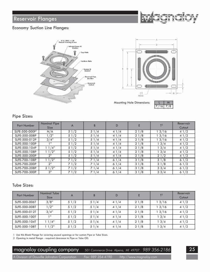
Reservoir FlangesEconomy Suction Line Flanges:
Mounting Hole Dimensions: L M7/16 7/8
Pipe Sizes:
Part NumberNominal Pipe
SizeA B D E T2
ReservoirCutout
SLFE-500-000P1 N/A 5 1/2 5 1/4 4 1/4 2 1/8 1 3/16 4 1/2SLFE-500-008P 1/2” 5 1/2 5 1/4 4 1/4 2 1/8 1 3/16 4 1/2SLFE-500-012P 3/4” 5 1/2 5 1/4 4 1/4 2 1/8 1 3/16 4 1/2SLFE-500-100P 1” 5 1/2 5 1/4 4 1/4 2 1/8 1 3/4 4 1/2SLFE-500-104P 1 1/4” 5 1/2 5 1/4 4 1/4 2 1/8 1 3/4 4 1/2SLFE-500-108P 1 1/2” 5 1/2 5 1/4 4 1/4 2 1/8 1 3/4 4 1/2SLFE-500-200P 2” 5 1/2 5 1/4 4 1/4 2 1/8 2 1/2 4 1/2SLFE-700-108P 1 1/2” 7 1/2 7 1/4 6 1/4 3 1/8 3 1/8 6 1/2SLFE-700-200P 2” 7 1/2 7 1/4 6 1/4 3 1/8 3 1/8 6 1/2SLFE-700-208P 2 1/2” 7 1/2 7 1/4 6 1/4 3 1/8 3 3/4 6 1/2SLFE-700-300P 3” 7 1/2 7 1/4 6 1/4 3 1/8 3 3/4 6 1/2
Tube Sizes:
Part NumberNominal Tube
SizeA B D E T2
ReservoirCutout
SLFE-500-006T 3/8” 5 1/2 5 1/4 4 1/4 2 1/8 1 3/16 4 1/2SLFE-500-008T 1/2” 5 1/2 5 1/4 4 1/4 2 1/8 1 3/16 4 1/2SLFE-500-012T 3/4” 5 1/2 5 1/4 4 1/4 2 1/8 1 3/16 4 1/2SLFE-500-100T 1” 5 1/2 5 1/4 4 1/4 2 1/8 1 3/4 4 1/2SLFE-500-104T 1 1/4” 5 1/2 5 1/4 4 1/4 2 1/8 1 3/4 4 1/2SLFE-500-108T 1 1/2” 5 1/2 5 1/4 4 1/4 2 1/8 1 3/4 4 1/2
1 Use this Blank Flange for covering unused openings or for custom Pipe or Tube Sizes.2 Opening in metal flange - required clearance to Pipe or Tube OD.
magnaloy coupling company 501 Commerce Drive Alpena, MI 49707 989 356-2186
A Division of Douville Johnston Corporation Fax: 989 354-4190 http://www.magnaloy.com
26
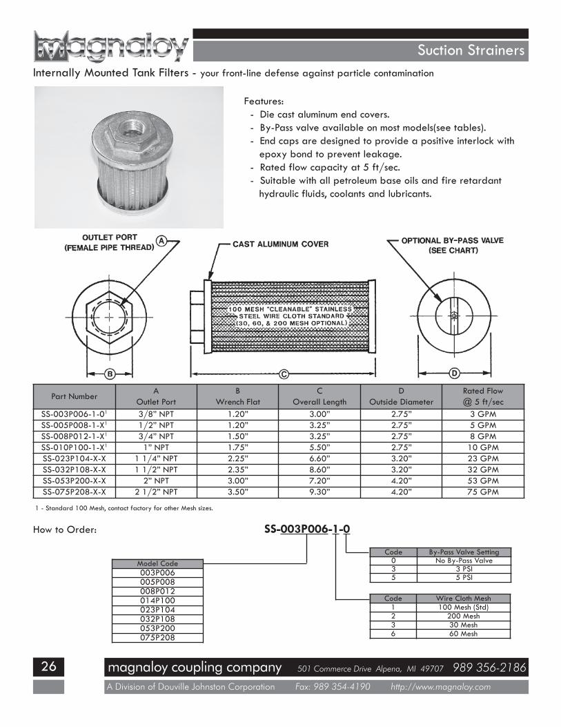
Suction Strainers
Features:- Die cast aluminum end covers.- By-Pass valve available on most models(see tables).- End caps are designed to provide a positive interlock withepoxy bond to prevent leakage.
- Rated flow capacity at 5 ft/sec.- Suitable with all petroleum base oils and fire retardanthydraulic fluids, coolants and lubricants.
Internally Mounted Tank Filters - your front-line defense against particle contamination
Part NumberA
Outlet PortB
Wrench FlatC
Overall LengthD
Outside DiameterRated Flow@ 5 ft/sec
SS-003P006-1-01 3/8” NPT 1.20” 3.00” 2.75” 3 GPMSS-005P008-1-X1 1/2” NPT 1.20” 3.25” 2.75” 5 GPMSS-008P012-1-X1 3/4” NPT 1.50” 3.25” 2.75” 8 GPMSS-010P100-1-X1 1” NPT 1.75” 5.50” 2.75” 10 GPMSS-023P104-X-X 1 1/4” NPT 2.25” 6.60” 3.20” 23 GPMSS-032P108-X-X 1 1/2” NPT 2.35” 8.60” 3.20” 32 GPMSS-053P200-X-X 2” NPT 3.00” 7.20” 4.20” 53 GPMSS-075P208-X-X 2 1/2” NPT 3.50” 9.30” 4.20” 75 GPM
How to Order: SS-003P006-1-0
Model Code003P006005P008008P012014P100023P104032P108053P200075P208
Code By-Pass Valve Setting0 No By-Pass Valve3 3 PSI5 5 PSI
Code Wire Cloth Mesh1 100 Mesh (Std)2 200 Mesh3 30 Mesh6 60 Mesh
1 - Standard 100 Mesh, contact factory for other Mesh sizes.
magnaloy coupling company 501 Commerce Drive Alpena, MI 49707 989 356-2186
A Division of Douville Johnston Corporation Fax: 989 354-4190 http://www.magnaloy.com
27
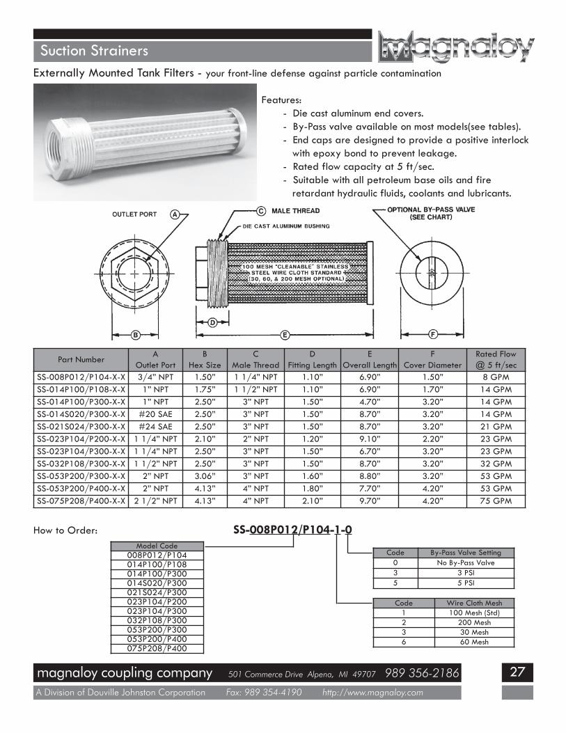
Suction StrainersExternally Mounted Tank Filters - your front-line defense against particle contamination
Features:- Die cast aluminum end covers.- By-Pass valve available on most models(see tables).- End caps are designed to provide a positive interlockwith epoxy bond to prevent leakage.
- Rated flow capacity at 5 ft/sec.- Suitable with all petroleum base oils and fireretardant hydraulic fluids, coolants and lubricants.
Part NumberA
Outlet PortB
Hex SizeC
Male ThreadD
Fitting LengthE
Overall LengthF
Cover DiameterRated Flow@ 5 ft/sec
SS-008P012/P104-X-X 3/4” NPT 1.50” 1 1/4” NPT 1.10” 6.90” 1.50” 8 GPMSS-014P100/P108-X-X 1” NPT 1.75” 1 1/2” NPT 1.10” 6.90” 1.70” 14 GPMSS-014P100/P300-X-X 1” NPT 2.50” 3” NPT 1.50” 4.70” 3.20” 14 GPMSS-014S020/P300-X-X #20 SAE 2.50” 3” NPT 1.50” 8.70” 3.20” 14 GPMSS-021S024/P300-X-X #24 SAE 2.50” 3” NPT 1.50” 8.70” 3.20” 21 GPMSS-023P104/P200-X-X 1 1/4” NPT 2.10” 2” NPT 1.20” 9.10” 2.20” 23 GPMSS-023P104/P300-X-X 1 1/4” NPT 2.50” 3” NPT 1.50” 6.70” 3.20” 23 GPMSS-032P108/P300-X-X 1 1/2” NPT 2.50” 3” NPT 1.50” 8.70” 3.20” 32 GPMSS-053P200/P300-X-X 2” NPT 3.06” 3” NPT 1.60” 8.80” 3.20” 53 GPMSS-053P200/P400-X-X 2” NPT 4.13” 4” NPT 1.80” 7.70” 4.20” 53 GPMSS-075P208/P400-X-X 2 1/2” NPT 4.13” 4” NPT 2.10” 9.70” 4.20” 75 GPM
How to Order: SS-008P012/P104-1-0Model Code
008P012/P104014P100/P108014P100/P300014S020/P300021S024/P300023P104/P200023P104/P300032P108/P300053P200/P300053P200/P400075P208/P400
Code By-Pass Valve Setting0 No By-Pass Valve3 3 PSI5 5 PSI
Code Wire Cloth Mesh1 100 Mesh (Std)2 200 Mesh3 30 Mesh6 60 Mesh
magnaloy coupling company 501 Commerce Drive Alpena, MI 49707 989 356-2186
A Division of Douville Johnston Corporation Fax: 989 354-4190 http://www.magnaloy.com
28
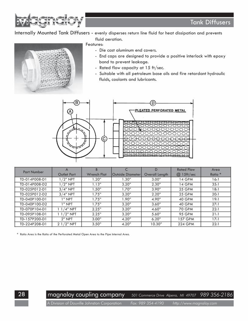
Tank DiffusersInternally Mounted Tank Diffusers - evenly disperses return line fluid for heat dissipation and prevents
fluid aeration.Features:
- Die cast aluminum end covers.- End caps are designed to provide a positive interlock with epoxybond to prevent leakage.
- Rated flow capacity at 15 ft/sec.- Suitable with all petroleum base oils and fire retardant hydraulicfluids, coolants and lubricants.
Part NumberA
Outlet PortB
Wrench FlatC
Outside DiameterD
Overall LengthRated Flow@ 15ft/sec
AreaRatio *
TD-014P008-D1 1/2” NPT 1.20” 1.30” 3.00” 14 GPM 16:1TD-014P008-D2 1/2” NPT 1.13” 3.20” 2.30” 14 GPM 35:1TD-025P012-D1 3/4” NPT 1.50” 1.70” 3.90” 25 GPM 18:1TD-025P012-D2 3/4” NPT 1.75” 3.20” 2.20” 25 GPM 20:1TD-040P100-D1 1” NPT 1.75” 1.90” 4.90” 40 GPM 19:1TD-040P100-D2 1” NPT 1.75” 3.20” 3.60” 40 GPM 27:1TD-070P104-D1 1 1/4” NPT 2.25” 3.20” 4.60” 70 GPM 22:1TD-095P108-D1 1 1/2” NPT 2.25” 3.20” 5.60” 95 GPM 21:1TD-157P200-D1 2” NPT 3.00” 4.20” 6.20” 157 GPM 17:1TD-224P208-D1 2 1/2” NPT 3.50” 4.20” 10.30” 224 GPM 22:1
* Ratio Area is the Ratio of the Perforated Metal Open Area to the Pipe Internal Area.
magnaloy coupling company 501 Commerce Drive Alpena, MI 49707 989 356-2186
A Division of Douville Johnston Corporation Fax: 989 354-4190 http://www.magnaloy.com
29
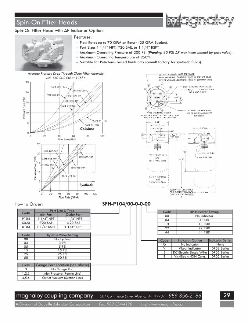
Spin-On Filter Heads
Features:- Flow Rates up to 70 GPM on Return (25 GPM Suction).- Port Sizes 1 1/4” NPT, #20 SAE, or 1 1/4” BSPT.- Maximum Operating Pressure of 200 PSI (Warning: 80 PSI ∆P maximum without by-pass valve).- Maximum Operating Temperature of 2500 F.- Suitable for Petroleum based fluids only (consult factory for synthetic fluids).
Spin-On Filter Head with ∆P Indicator Option:
How to Order: SFH-P104/00-0-0-00
Code Port Size & TypeInlet Port Outlet Port
P104 1 1/4” NPT 1 1/4” NPTS020 #20 SAE #20 SAEB104 1 1/4” BSPT 1 1/4” BSPT
Code By-Pass Valve Setting00 No By-Pass03 3 PSI05 5 PSI15 15 PSI25 25 PSI50 50 PSI
Code Gauge Port Location (see above)0 No Gauge Port
1,2,3 Inlet Pressure (Return Line)4,5,6 Outlet Vacuum (Suction Line)
Code ∆P Indicator Setting00 No Indicator04 4 PSID13 13 PSID22 22 PSID44 44 PSID
Code Indicator Option Indicator SeriesO No Indicator NoneV Visual Indicator DP03 SeriesE DC Electric Single Wire DP06 SeriesB Vis/Elec w/DIN Conn. DP05 Series
0
5
10
15
20
25
0 20 40 60 80 100
Pre
ssur
eD
rop
(PS
I)
Flow Rate (GPM)
CSFE-003-109
CSFE-003-069
CSFE-025-069
CSFE-025-109
CSFE-010-109
CSFE-010-069
CSFE-141-109
CSFE-141-069
Average Pressure Drop Through Clean Filter Assemblywith 150 SUS Oil at 1050 F.
Cellulose
Synthetic
magnaloy coupling company 501 Commerce Drive Alpena, MI 49707 989 356-2186
A Division of Douville Johnston Corporation Fax: 989 354-4190 http://www.magnaloy.com
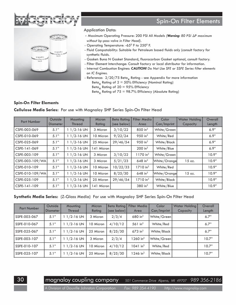
30
Spin-On Filter ElementsApplication Data:- Maximum Operating Pressure: 200 PSI All Models (Warning: 80 PSI ∆P maximumwithout by-pass valve in Filter Head).
- Operating Temperature: -650 F to 2500 F.- Fluid Compatability: Suitable for Petroleum based fluids only (consult factory forsynthetic fluids.
- Gasket: Buna N Gasket Standard, fluorocarbon Gasket optional, consult factory.- Filter Element Interchange: Consult factory or local distributor for information.- Internal Combustion Engines: CAUTION! Do Not Use SFE or SSFE Series filter elementson IC Engines.
- Reference: 2/20/75 Betax Rating - see Appendix for more informationBetax Rating of 2 = 50% Efficiency (Nominal Rating)Betax Rating of 20 = 95% EfficiencyBetax Rating of 75 = 98.7% Efficiency (Absolute Rating)
Part NumberOutsideDiameter
MountingThread
MicronRating
Beta Rating(see below)
Filter MediaArea
ColorCan/Imprint
Water HoldingCapacity
OverallLength
CSFE-003-069 5.1” 1 1/2-16 UN 3 Micron 3/10/22 850 in2 White/Green 6.9”
CSFE-010-069 5.1” 1 1/2-16 UN 10 Micron 9/22/24 950 in2 White/Red 6.9”
CSFE-025-069 5.1” 1 1/2-16 UN 25 Micron 29/46/54 950 in2 White/Black 6.9”
CSFE-141-069 5.1” 1 1/2-16 UN 141 Micron 200 in2 White/Blue 6.9”
CSFE-003-109 5.1” 1 1/2-16 UN 3 Micron 3/10/22 1170 in2 White/Green 10.9”
CSFE-003-109/WA 5.1” 1 1/2-16 UN 3 Micron 5/21/23 648 in2 White/Orange 15 oz. 10.9”
CSFE-010-109 5.1” 1 1/2-16 UN 10 Micron 10/22/33 1710 in2 White/Red 10.9”
CSFE-010-109/WA 5.1” 1 1/2-16 UN 10 Micron 8/25/30 648 in2 White/Orange 15 oz. 10.9”
CSFE-025-109 5.1” 1 1/2-16 UN 25 Micron 29/46/54 1710 in2 White/Black 10.9”
CSFE-141-109 5.1” 1 1/2-16 UN 141 Micron 380 in2 White/Blue 10.9”
Cellulose Media Series: For use with Magnaloy SHF Series Spin-On Filter Head
Synthetic Media Series: (Z-Glass Media) For use with Magnaloy SHF Series Spin-On Filter Head
Part NumberOutsideDiameter
MountingThread
MicronRating
Beta Rating(see below)
Filter MediaArea
ColorCan/Imprint
Water HoldingCapacity
OverallLength
SSFE-003-067 5.1” 1 1/2-16 UN 3 Micron 2/3/4 680 in2 White/Green 6.7”
SSFE-010-067 5.1” 1 1/2-16 UN 10 Micron 4/10/12 561 in2 White/Red 6.7”
SSFE-025-067 5.1” 1 1/2-16 UN 25 Micron 8/25/30 673 in2 White/Black 6.7”
SSFE-003-107 5.1” 1 1/2-16 UN 3 Micron 2/3/4 1260 in2 White/Green 10.7”
SSFE-010-107 5.1” 1 1/2-16 UN 10 Micron 4/10/12 1041 in2 White/Red 10.7”
SSFE-025-107 5.1” 1 1/2-16 UN 25 Micron 8/25/30 1246 in2 White/Black 10.7”
Spin-On Filter Elements
magnaloy coupling company 501 Commerce Drive Alpena, MI 49707 989 356-2186
A Division of Douville Johnston Corporation Fax: 989 354-4190 http://www.magnaloy.com
31
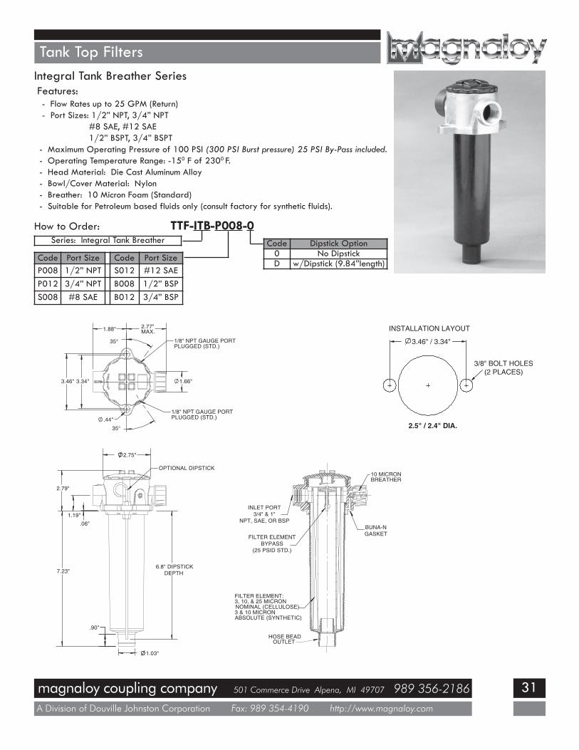
Tank Top FiltersIntegral Tank Breather SeriesFeatures:- Flow Rates up to 25 GPM (Return)- Port Sizes: 1/2” NPT, 3/4” NPT
#8 SAE, #12 SAE1/2” BSPT, 3/4” BSPT
- Maximum Operating Pressure of 100 PSI (300 PSI Burst pressure) 25 PSI By-Pass included.- Operating Temperature Range: -150 F of 2300 F.- Head Material: Die Cast Aluminum Alloy- Bowl/Cover Material: Nylon- Breather: 10 Micron Foam (Standard)- Suitable for Petroleum based fluids only (consult factory for synthetic fluids).
How to Order: TTF-ITB-P008-0
Code Port Size Code Port SizeP008 1/2” NPT S012 #12 SAEP012 3/4” NPT B008 1/2” BSPS008 #8 SAE B012 3/4” BSP
Code Dipstick Option0 No DipstickD w/Dipstick (9.84”length)
Series: Integral Tank Breather
3.46" 3.34"
1.88" 2.77"MAX.
35°
35°
1.66"
.44"
1/8" NPT GAUGE PORTPLUGGED (STD.)
1/8" NPT GAUGE PORTPLUGGED (STD.)
2.75"
2.79"
.06"1.19"
7.23"6.8" DIPSTICK
DEPTH
.90"
1.03"
OPTIONAL DIPSTICK
HOSE BEADOUTLET
FILTER ELEMENT:3, 10, & 25 MICRONNOMINAL (CELLULOSE)3 & 10 MICRONABSOLUTE (SYNTHETIC)
FILTER ELEMENTBYPASS
(25 PSID STD.)
INLET PORT3/4" & 1"
NPT, SAE, OR BSP
10 MICRONBREATHER
BUNA-NGASKET
3.46" / 3.34"
2.5" / 2.4" DIA.
3/8" BOLT HOLES(2 PLACES)
INSTALLATION LAYOUT
magnaloy coupling company 501 Commerce Drive Alpena, MI 49707 989 356-2186
A Division of Douville Johnston Corporation Fax: 989 354-4190 http://www.magnaloy.com
32
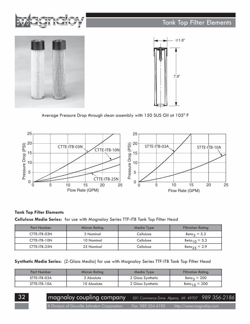
Tank Top Filter Elements
7.9"
1.8"
Average Pressure Drop through clean assembly with 150 SUS Oil at 1050 F
Part Number Micron Rating Media Type Filtration Rating
CTTE-ITB-03N 3 Nominal Cellulose Beta3 = 5.3
CTTE-ITB-10N 10 Nominal Cellulose Beta10 = 5.3
CTTE-ITB-25N 25 Nominal Cellulose Beta25 = 2.9
Cellulose Media Series: for use with Magnaloy Series TTF-ITB Tank Top Filter HeadTank Top Filter Elements
Part Number Micron Rating Media Type Filtration RatingSTTE-ITB-03A 3 Absolute Z Glass Synthetic Beta3 = 200STTE-ITB-10A 10 Absolute Z Glass Synthetic Beta10 = 200
Synthetic Media Series: (Z-Glass Media) for use with Magnaloy Series TTF-ITB Tank Top Filter Head
magnaloy coupling company 501 Commerce Drive Alpena, MI 49707 989 356-2186
A Division of Douville Johnston Corporation Fax: 989 354-4190 http://www.magnaloy.com
33
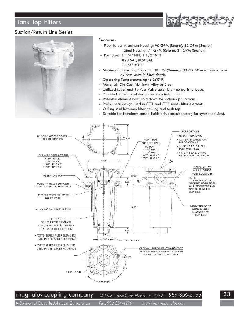
Tank Top Filters
Features:- Flow Rates: Aluminum Housing; 96 GPM (Return), 32 GPM (Suction)
Steel Housing; 71 GPM (Return), 24 GPM (Suction)- Port Sizes: 1 1/4” NPT, 1 1/2” NPT
#20 SAE, #24 SAE1 1/4” BSPT
- Maximum Operating Pressure: 100 PSI (Warning: 80 PSI ∆P maximum withoutby-pass valve in Filter Head).
- Operating Temperature: up to 2500 F.- Material: Die Cast Aluminum Alloy or Steel- Unitized cover and By-Pass Valve assembly - no parts to loose.- Drop-in Element Bowl design for easy installation- Patented element bowl hold down for suction applications.- Radial seal design used in CTTE and STTE series filter elements- O-Ring seal between filter housing and tank top- Suitable for Petroleum based fluids only (consult factory for synthetic fluids).
Suction/Return Line Series
magnaloy coupling company 501 Commerce Drive Alpena, MI 49707 989 356-2186
A Division of Douville Johnston Corporation Fax: 989 354-4190 http://www.magnaloy.com
34
Tank Top Filters
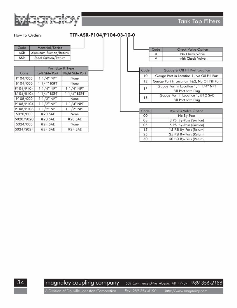
How to Order: TTF-ASR-P104/P104-03-10-0
Code Material/SeriesASR Aluminum Suction/ReturnSSR Steel Suction/Return
CodePort Size & Type
Left Side Port Right Side PortP104/000 1 1/4” NPT NoneB104/000 1 1/4” BSPT NoneP104/P104 1 1/4” NPT 1 1/4” NPTB104/B104 1 1/4” BSPT 1 1/4” BSPTP108/000 1 1/2” NPT NoneP108/P104 1 1/2” NPT 1 1/4” NPTP108/P108 1 1/2” NPT 1 1/2” NPTS020/000 #20 SAE NoneS020/S020 #20 SAE #20 SAES024/000 #24 SAE NoneS024/S024 #24 SAE #24 SAE
Code Check Valve Option0 No Check ValveV with Check Valve
Code Gauge & Oil Fill Port Location10 Gauge Port in Location 1, No Oil Fill Port12 Gauge Port in Location 1&2, No Oil Fill Port
1PGauge Port in Location 1, 1 1/4” NPT
Fill Port with Plug
1SGauge Port in Location 1, #12 SAE
Fill Port with Plug
Code By-Pass Valve Option00 No By-Pass03 3 PSI By-Pass (Suction)05 5 PSI By-Pass (Suction)15 15 PSI By-Pass (Return)25 25 PSI By-Pass (Return)50 50 PSI By-Pass (Return)

magnaloy coupling company 501 Commerce Drive Alpena, MI 49707 989 356-2186
A Division of Douville Johnston Corporation Fax: 989 354-4190 http://www.magnaloy.com
35
Tank Top Filter Elements
Part NumberFiltrationRating
FiltrationRating
Filter MediaArea
AOD
BID
CLength
Flow DirectionThru Element
CTTE-ASR-003-092-BD Beta3 = 5.3 Beta10 = 75 1120 in2 3.91” 1.96” 9.19” Bi-Directional
CTTE-ASR-003-092-OI/WA** Beta3 = 5.3 Beta10 = 75 461 in2 3.91” 1.96” 9.19” Outside to Inside
CTTE-ASR-010-092-BD Beta10 = 5.3 Beta22 = 75 1120 in2 3.91” 1.96” 9.19” Bi-Directional
CTTE-ASR-025-092-BD Beta25 = 2.9 Beta47 = 20 1120 in2 3.91” 1.96” 9.19” Bi-Directional
CTTE-ASR-010-182-BD Beta10 = 5.3 Beta22 = 75 2240 in2 3.91” 1.96” 18.19” Bi-Directional
CTTE-ASR-025-182-BD Beta25 = 2.9 Beta47 = 20 2240 in2 3.91” 1.96” 18.19” Bi-Directional
CTTE-ASR-100-092-OI* 141 Micron 151 in2 3.91” 1.96” 9.19” Outside to Inside
CTTE-ASR-100-092-IO* 141 Micron 151 in2 3.91” 1.96” 9.19” Inside to Outside
CTTE-ASR-100-092-OI/M* 141 Micron 109 in2 3.91” 1.96” 9.19” Outside to Inside
CTTE-ASR-100-092-IO/M* 141 Micron 109 in2 3.91” 1.96” 9.19” Inside to Outside
CTTE-ASR-100-182-OI* 141 Micron 2240 in2 3.91” 1.96” 18.19” Outside to Inside
Cellulose Media Series: for use with Magnaloy Series TTF-ASR Tank Top Filter
Note:* 100 Mesh Stainless Steel Wire Cloth is standard for 141 Micron Elements, 30, 60 & 200 optional - consult factory
** Filter Elements CTTE-ASR-409-03-IO/WA & CTTE-ASR-409-10-OI/WA contain Aqua-Zorb (water absorbing) filter media.ASR Elements come standard with a Buna-N radial seal, Fluorocarbon optional -consult factory
Part NumberFiltrationRating
FiltrationRating
Filter MediaArea
AOD
BID
CLength
Flow DirectionThru Element
STTE-ASR-003-092-OI Beta3 > 200 825 in2 3.91” 1.96” 9.19” Outside to InsideSTTE-ASR-010-092-OI Beta10 > 200 825 in2 3.91” 1.96” 9.19” Outside to InsideSTTE-ASR-003-182-OI Beta3 > 200 1650 in2 3.91” 1.96” 18.19” Outside to InsideSTTE-ASR-010-182-OI Beta10 > 200 1650 in2 3.91” 1.96” 18.19” Outside to Inside
Synthetic Media Series: for use with Magnaloy Series TTF-ASR Tank Top Filter
Magnetic Elements
Part NumbersCTTE-ASR-100-092-OI/MCTTE-ASR-100-092-IO/M
Three - 4” diameter x 5/8”thick ceramic magnets
Four - 100 meshwire cloth filter sections
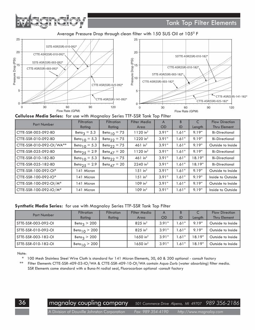
magnaloy coupling company 501 Commerce Drive Alpena, MI 49707 989 356-2186
A Division of Douville Johnston Corporation Fax: 989 354-4190 http://www.magnaloy.com
36
Tank Top Filter Elements
Cellulose Media Series: for use with Magnaloy Series TTF-SSR Tank Top Filter
Part NumberFiltrationRating
FiltrationRating
Filter MediaArea
AOD
BID
CLength
Flow DirectionThru Element
CTTE-SSR-003-092-BD Beta3 = 5.3 Beta10 = 75 1120 in2 3.91” 1.61” 9.19” Bi-Directional
CTTE-SSR-010-092-BD Beta10 = 5.3 Beta22 = 75 1220 in2 3.91” 1.61” 9.19” Bi-Directional
CTTE-SSR-010-092-OI/WA** Beta10 = 5.3 Beta22 = 75 461 in2 3.91” 1.61” 9.19” Outside to Inside
CTTE-SSR-025-092-BD Beta25 = 2.9 Beta47 = 20 1120 in2 3.91” 1.61” 9.19” Bi-Directional
CTTE-SSR-010-182-BD Beta10 = 5.3 Beta22 = 75 461 in2 3.91” 1.61” 18.19” Bi-Directional
CTTE-SSR-025-182-BD Beta25 = 2.9 Beta47 = 20 2240 in2 3.91” 1.61” 18.19” Bi-Directional
CTTE-SSR-100-092-OI* 141 Micron 151 in2 3.91” 1.61” 9.19” Outside to Inside
CTTE-SSR-100-092-IO* 141 Micron 151 in2 3.91” 1.61” 9.19” Inside to Outside
CTTE-SSR-100-092-OI/M* 141 Micron 109 in2 3.91” 1.61” 9.19” Outside to Inside
CTTE-SSR-100-092-IO/M* 141 Micron 109 in2 3.91” 1.61” 9.19” Inside to Outside
Synthetic Media Series: for use with Magnaloy Series TTF-SSR Tank Top Filter
Part NumberFiltrationRating
FiltrationRating
Filter MediaArea
AOD
BID
CLength
Flow DirectionThru Element
STTE-SSR-003-092-OI Beta3 > 200 825 in2 3.91” 1.61” 9.19” Outside to Inside
STTE-SSR-010-092-OI Beta10 > 200 825 in2 3.91” 1.61” 9.19” Outside to Inside
STTE-SSR-003-182-OI Beta3 > 200 1650 in2 3.91” 1.61” 18.19” Outside to Inside
STTE-SSR-010-182-OI Beta10 > 200 1650 in2 3.91” 1.61” 18.19” Outside to Inside
Note:* 100 Mesh Stainless Steel Wire Cloth is standard for 141 Micron Elements, 30, 60 & 200 optional - consult factory
** Filter Elements CTTE-SSR-409-03-IO/WA & CTTE-SSR-409-10-OI/WA contain Aqua-Zorb (water absorbing) filter media.SSR Elements come standard with a Buna-N radial seal, Fluorocarbon optional -consult factory
Average Pressure Drop through clean filter with 150 SUS Oil at 1050 F
magnaloy coupling company 501 Commerce Drive Alpena, MI 49707 989 356-2186
A Division of Douville Johnston Corporation Fax: 989 354-4190 http://www.magnaloy.com
37
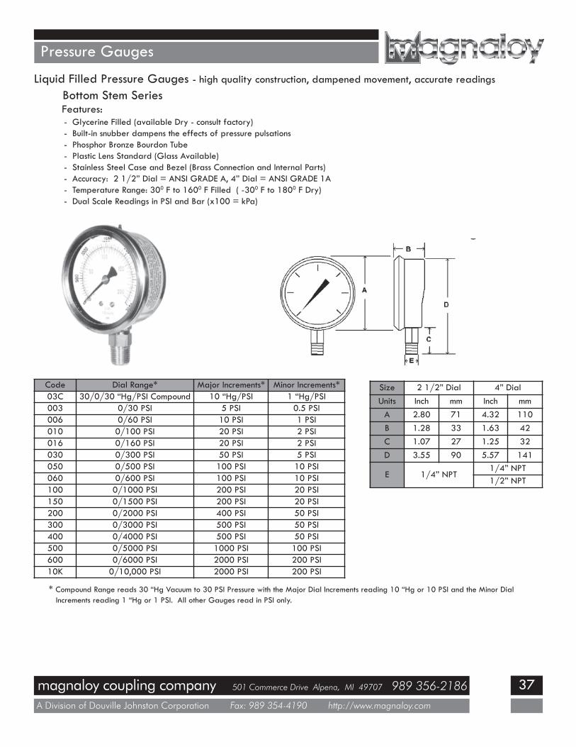
Pressure Gauges
Liquid Filled Pressure Gauges - high quality construction, dampened movement, accurate readings
Features:- Glycerine Filled (available Dry - consult factory)- Built-in snubber dampens the effects of pressure pulsations- Phosphor Bronze Bourdon Tube- Plastic Lens Standard (Glass Available)- Stainless Steel Case and Bezel (Brass Connection and Internal Parts)- Accuracy: 2 1/2” Dial = ANSI GRADE A, 4” Dial = ANSI GRADE 1A- Temperature Range: 300 F to 1600 F Filled ( -300 F to 1800 F Dry)- Dual Scale Readings in PSI and Bar (x100 = kPa)
Bottom Stem Series
Code Dial Range* Major Increments* Minor Increments*03C 30/0/30 “Hg/PSI Compound 10 “Hg/PSI 1 “Hg/PSI003 0/30 PSI 5 PSI 0.5 PSI006 0/60 PSI 10 PSI 1 PSI010 0/100 PSI 20 PSI 2 PSI016 0/160 PSI 20 PSI 2 PSI030 0/300 PSI 50 PSI 5 PSI050 0/500 PSI 100 PSI 10 PSI060 0/600 PSI 100 PSI 10 PSI100 0/1000 PSI 200 PSI 20 PSI150 0/1500 PSI 200 PSI 20 PSI200 0/2000 PSI 400 PSI 50 PSI300 0/3000 PSI 500 PSI 50 PSI400 0/4000 PSI 500 PSI 50 PSI500 0/5000 PSI 1000 PSI 100 PSI600 0/6000 PSI 2000 PSI 200 PSI10K 0/10,000 PSI 2000 PSI 200 PSI
* Compound Range reads 30 “Hg Vacuum to 30 PSI Pressure with the Major Dial Increments reading 10 “Hg or 10 PSI and the Minor DialIncrements reading 1 “Hg or 1 PSI. All other Gauges read in PSI only.
Size 2 1/2” Dial 4” DialUnits Inch mm Inch mmA 2.80 71 4.32 110B 1.28 33 1.63 42C 1.07 27 1.25 32D 3.55 90 5.57 141
E 1/4” NPT1/4” NPT1/2” NPT
magnaloy coupling company 501 Commerce Drive Alpena, MI 49707 989 356-2186
A Division of Douville Johnston Corporation Fax: 989 354-4190 http://www.magnaloy.com
38
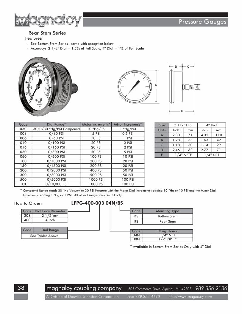
Pressure Gauges
Rear Stem SeriesFeatures:- See Bottom Stem Series - same with exception below- Accuracy: 2 1/2” Dial = 1.5% of Full Scale, 4” Dial = 1% of Full Scale
Code Dial Range* Major Increments* Minor Increments*03C 30/0/30 “Hg/PSI Compound 10 “Hg/PSI 1 “Hg/PSI003 0/30 PSI 5 PSI 0.5 PSI006 0/60 PSI 10 PSI 1 PSI010 0/100 PSI 20 PSI 2 PSI016 0/160 PSI 20 PSI 2 PSI030 0/300 PSI 50 PSI 5 PSI060 0/600 PSI 100 PSI 10 PSI100 0/1000 PSI 200 PSI 20 PSI150 0/1500 PSI 200 PSI 20 PSI200 0/2000 PSI 400 PSI 50 PSI300 0/3000 PSI 500 PSI 50 PSI500 0/5000 PSI 1000 PSI 100 PSI10K 0/10,000 PSI 1000 PSI 100 PSI
Size 2 1/2” Dial 4” DialUnits Inch mm Inch mmA 2.80 71 4.32 110B 1.28 33 1.63 42C 1.18 30 1.14 29D 2.46 63 2.77 71E 1/4” NPTF 1/4” NPT
* Compound Range reads 30 “Hg Vacuum to 30 PSI Pressure with the Major Dial Increments reading 10 “Hg or 10 PSI and the Minor DialIncrements reading 1 “Hg or 1 PSI. All other Gauges read in PSI only.
How to Order: LFPG-400-003 04N/BSCode Dial Face Diameter208 2 1/2 inch400 4 inch
Code Dial Range
See Tables Above
Code Mounting TypeBS Bottom StemRS Rear Stem
Code Fitting Thread04N 1/4” NPT08N 1/2” NPT *
* Available in Bottom Stem Series Only with 4” Dial
magnaloy coupling company 501 Commerce Drive Alpena, MI 49707 989 356-2186
A Division of Douville Johnston Corporation Fax: 989 354-4190 http://www.magnaloy.com
39
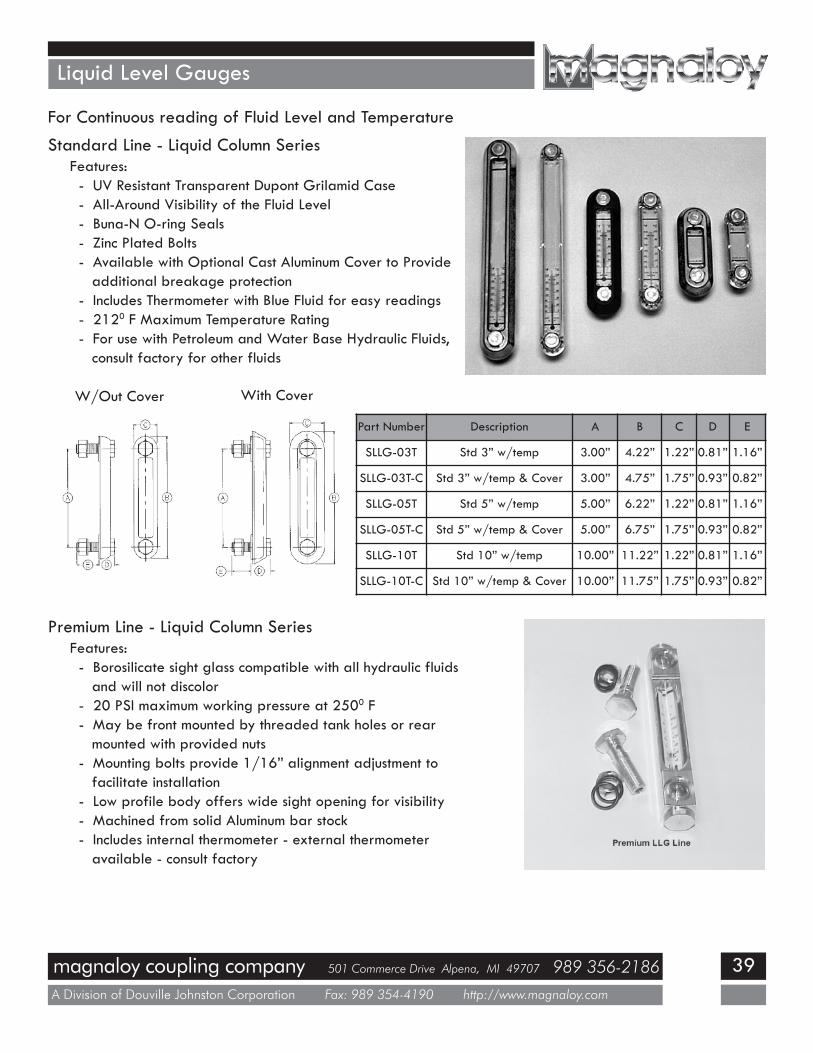
Liquid Level Gauges
For Continuous reading of Fluid Level and Temperature
Standard Line - Liquid Column SeriesFeatures:- UV Resistant Transparent Dupont Grilamid Case- All-Around Visibility of the Fluid Level- Buna-N O-ring Seals- Zinc Plated Bolts- Available with Optional Cast Aluminum Cover to Provideadditional breakage protection
- Includes Thermometer with Blue Fluid for easy readings- 2120 F Maximum Temperature Rating- For use with Petroleum and Water Base Hydraulic Fluids,consult factory for other fluids
W/Out Cover With Cover
Part Number Description A B C D E
SLLG-03T Std 3” w/temp 3.00” 4.22” 1.22” 0.81” 1.16”
SLLG-03T-C Std 3” w/temp & Cover 3.00” 4.75” 1.75” 0.93” 0.82”
SLLG-05T Std 5” w/temp 5.00” 6.22” 1.22” 0.81” 1.16”
SLLG-05T-C Std 5” w/temp & Cover 5.00” 6.75” 1.75” 0.93” 0.82”
SLLG-10T Std 10” w/temp 10.00” 11.22” 1.22” 0.81” 1.16”
SLLG-10T-C Std 10” w/temp & Cover 10.00” 11.75” 1.75” 0.93” 0.82”
Premium Line - Liquid Column SeriesFeatures:- Borosilicate sight glass compatible with all hydraulic fluidsand will not discolor
- 20 PSI maximum working pressure at 2500 F- May be front mounted by threaded tank holes or rearmounted with provided nuts
- Mounting bolts provide 1/16” alignment adjustment tofacilitate installation
- Low profile body offers wide sight opening for visibility- Machined from solid Aluminum bar stock- Includes internal thermometer - external thermometeravailable - consult factory
magnaloy coupling company 501 Commerce Drive Alpena, MI 49707 989 356-2186
A Division of Douville Johnston Corporation Fax: 989 354-4190 http://www.magnaloy.com
40
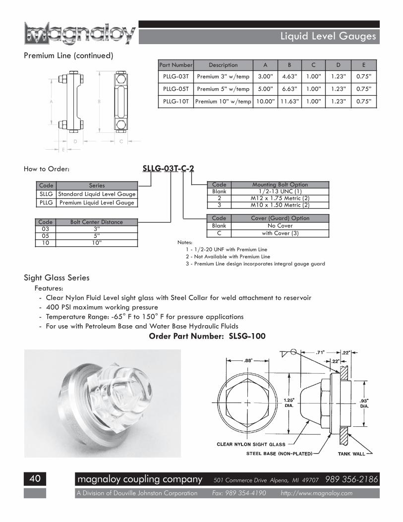
Liquid Level Gauges
Part Number Description A B C D E
PLLG-03T Premium 3” w/temp 3.00” 4.63” 1.00” 1.23” 0.75”
PLLG-05T Premium 5” w/temp 5.00” 6.63” 1.00” 1.23” 0.75”
PLLG-10T Premium 10” w/temp 10.00” 11.63” 1.00” 1.23” 0.75”
Premium Line (continued)
Sight Glass SeriesFeatures:- Clear Nylon Fluid Level sight glass with Steel Collar for weld attachment to reservoir- 400 PSI maximum working pressure- Temperature Range: -65° F to 150° F for pressure applications- For use with Petroleum Base and Water Base Hydraulic Fluids
Order Part Number: SLSG-100
How to Order: SLLG-03T-C-2
Code SeriesSLLG Standard Liquid Level GaugePLLG Premium Liquid Level Gauge
Code Bolt Center Distance03 3”05 5”10 10”
Code Mounting Bolt OptionBlank 1/2-13 UNC (1)2 M12 x 1.75 Metric (2)3 M10 x 1.50 Metric (2)
Code Cover (Guard) OptionBlank No CoverC with Cover (3)
Notes:1 - 1/2-20 UNF with Premium Line2 - Not Available with Premium Line3 - Premium Line design incorporates integral gauge guard
magnaloy coupling company 501 Commerce Drive Alpena, MI 49707 989 356-2186
A Division of Douville Johnston Corporation Fax: 989 354-4190 http://www.magnaloy.com
41
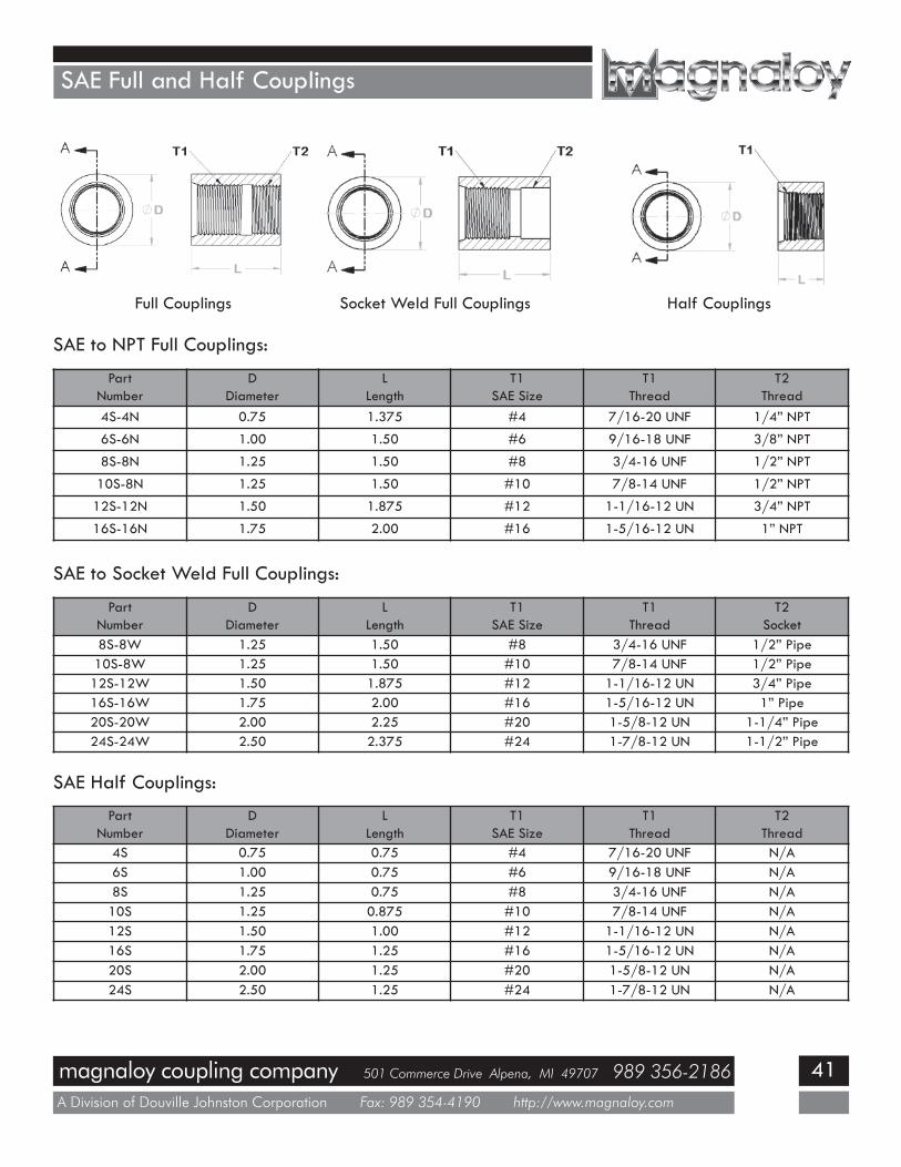
SAE Full and Half Couplings
SAE to NPT Full Couplings:
PartNumber
DDiameter
LLength
T1SAE Size
T1Thread
T2Thread
4S-4N 0.75 1.375 #4 7/16-20 UNF 1/4” NPT
6S-6N 1.00 1.50 #6 9/16-18 UNF 3/8” NPT
8S-8N 1.25 1.50 #8 3/4-16 UNF 1/2” NPT
10S-8N 1.25 1.50 #10 7/8-14 UNF 1/2” NPT
12S-12N 1.50 1.875 #12 1-1/16-12 UN 3/4” NPT
16S-16N 1.75 2.00 #16 1-5/16-12 UN 1” NPT
SAE to Socket Weld Full Couplings:
PartNumber
DDiameter
LLength
T1SAE Size
T1Thread
T2Socket
8S-8W 1.25 1.50 #8 3/4-16 UNF 1/2” Pipe10S-8W 1.25 1.50 #10 7/8-14 UNF 1/2” Pipe12S-12W 1.50 1.875 #12 1-1/16-12 UN 3/4” Pipe16S-16W 1.75 2.00 #16 1-5/16-12 UN 1” Pipe20S-20W 2.00 2.25 #20 1-5/8-12 UN 1-1/4” Pipe24S-24W 2.50 2.375 #24 1-7/8-12 UN 1-1/2” Pipe
SAE Half Couplings:
PartNumber
DDiameter
LLength
T1SAE Size
T1Thread
T2Thread
4S 0.75 0.75 #4 7/16-20 UNF N/A6S 1.00 0.75 #6 9/16-18 UNF N/A8S 1.25 0.75 #8 3/4-16 UNF N/A10S 1.25 0.875 #10 7/8-14 UNF N/A12S 1.50 1.00 #12 1-1/16-12 UN N/A16S 1.75 1.25 #16 1-5/16-12 UN N/A20S 2.00 1.25 #20 1-5/8-12 UN N/A24S 2.50 1.25 #24 1-7/8-12 UN N/A
Full Couplings Socket Weld Full Couplings Half Couplings
magnaloy coupling company 501 Commerce Drive Alpena, MI 49707 989 356-2186
A Division of Douville Johnston Corporation Fax: 989 354-4190 http://www.magnaloy.com
42
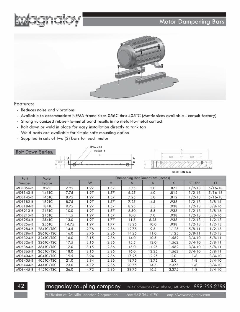
Motor Dampening Bars
Features:- Reduces noise and vibrations- Available to accommodate NEMA frame sizes 056C thru 405TC (Metric sizes available - consult factory)- Strong vulcanized rubber-to-metal bond results in no metal-to-metal contact- Bolt down or weld in place for easy installation directly to tank top- Weld pads are available for simple safe mounting option- Supplied in sets of two (2) bars for each motor
PartNumber
MotorFrame
Dampening Bar Dimensions (inches)L W H A B X C1 for T1
MDB056-B 056C 7.25 1.97 1.57 5.75 3.0 .875 1/2-13 5/16-18MDB143-B 143TC 7.75 1.97 1.57 6.25 4.0 .812 1/2-13 5/16-18MDB145-B 145TC 8.75 1.97 1.57 7.25 5.0 .812 1/2-13 5/16-18MDB182-B 182TC 8.75 1.97 1.57 7.25 4.5 .938 1/2-13 3/8-16MDB184-B 184TC 9.75 1.97 1.57 8.25 5.5 .938 1/2-13 3/8-16MDB213-B 213TC 10.0 1.97 1.57 8.50 5.5 .938 1/2-13 3/8-16MDB215-B 215TC 11.5 1.97 1.57 10.0 7.0 .938 1/2-13 3/8-16MDB254-B 254TC 13.0 1.97 1.77 11.5 8.25 .938 1/2-13 1/2-13MDB256-B 256TC 14.75 1.97 1.77 13.25 10.0 .938 1/2-13 1/2-13MDB284-B 284TC/TSC 14.5 2.76 2.36 12.75 9.5 1.125 5/8-11 1/2-13MDB286-B 286TC/TSC 16.0 2.76 2.36 14.25 11.0 1.125 5/8-11 1/2-13MDB324-B 324TC/TSC 16.0 3.15 2.36 14.0 10.5 1.562 3/4-10 5/8-11MDB326-B 326TC/TSC 17.5 3.15 2.36 15.5 12.0 1.562 3/4-10 5/8-11MDB364-B 364TC/TSC 17.0 3.15 2.36 15.0 11.25 1.562 3/4-10 5/8-11MDB365-B 365TC/TSC 18.0 3.15 2.36 16.0 12.25 1.562 3/4-10 5/8-11MDB404-B 404TC/TSC 19.5 3.94 2.36 17.25 12.25 2.0 1-8 3/4-10MDB405-B 405TC/TSC 21.0 3.94 2.36 18.75 13.75 2.0 1-8 3/4-10MDB444-B 444TC/TSC 23.0 4.72 2.36 20.75 14.5 2.375 1-8 3/4-10MDB445-B 445TC/TSC 26.0 4.72 2.36 23.75 16.5 2.375 1-8 3/4-10
Bolt Down Series:

magnaloy coupling company 501 Commerce Drive Alpena, MI 49707 989 356-2186
A Division of Douville Johnston Corporation Fax: 989 354-4190 http://www.magnaloy.com
43
Motor Dampening Bars
Weld Series:
PartNumber
MotorFrame
Dampening Bar Dimensions (inches)L W H B X T1
MDB056-W 056C 4.75 1.97 1.57 3.0 .875 5/16-18MDB143-W 143TC 5.50 1.97 1.57 4.0 .812 5/16-18MDB145-W 145TC 6.50 1.97 1.57 5.0 .812 5/16-18MDB182-W 182TC 6.0 1.97 1.57 4.5 .938 3/8-16MDB184-W 184TC 7.0 1.97 1.57 5.5 .938 3/8-16MDB213-W 213TC 7.75 1.97 1.57 5.5 .938 3/8-16MDB215-W 215TC 9.0 1.97 1.57 7.0 .938 3/8-16MDB254-W 254TC 10.5 1.97 1.77 8.25 .938 1/2-13MDB256-W 256TC 12.25 1.97 1.77 10.0 .938 1/2-13MDB284W 284TC/TSC 12.0 2.76 2.36 9.5 1.125 1/2-13MDB286-W 286TC/TSC 13.25 2.76 2.36 11.0 1.125 1/2-13MDB324-W 324TC/TSC 12.5 3.15 2.36 10.5 1.562 5/8-11MDB326-W 326TC/TSC 14 3.15 2.36 12.0 1.562 5/8-11MDB364-W 364TC/TSC 13.5 3.15 2.36 11.25 1.562 5/8-11MDB365-W 365TC/TSC 14.5 3.15 2.36 12.25 1.562 5/8-11MDB404-W 404TC/TSC 15.5 3.94 2.36 12.25 2.0 3/4-10MDB405-W 405TC/TSC 17.0 3.94 2.36 13.75 2.0 3/4-10MDB444-W 444TC/TSC 19.5 4.72 2.36 14.5 2.375 3/4-10MDB445-W 445TC/TSC 21.0 4.72 2.36 16.5 2.375 3/4-10
CAUTION !Welding Directly to the Magnaloy Motor Dampening Bar can cause damage to the metal-to-rubber bondresulting in premature failure. Welding should be limited to the ends only (across the “W” dimension) toprevent damage to the rubber vulcanization by the heat generated during the welding process. Extremecare should be exercised whenever welding to assemblies containing vulcanized rubber. Bond Separationwill occur if the metal/rubber surface interface reaches a temperature above 500 0F.
Magnaloy offers a solution to this situation - the Magnaloy Weld Pad Kit.
See page 44 for details.

magnaloy coupling company 501 Commerce Drive Alpena, MI 49707 989 356-2186
A Division of Douville Johnston Corporation Fax: 989 354-4190 http://www.magnaloy.com
44
Motor Dampening Bars
Weld Pad Kit:
PartNumber
Fits MotorFrames
Weld Pad Dimensions (inches)W H T1
MWP056-256 056C thru 256TC 2.0 .50 1/2-13 UNC
MWP284-286 284TC/TSC thru 286TC/TSC 2.75 .50 5/8-11 UNC
MWP324-365 324TC/TSC thru 365TC/TSC 2.75 .75 3/4-10 UNC
MWP404-405 404TC/TSC thru 405TC/TSC 4.0 .75 3/4-10 UNC
MWP444-445 444TC/TSC thru 445TC/TSC 4.75 .75 1-8 UNC
Features:- Allows simple bolt down installation and design flexibility with drilling and tapping the reservoir surface.- Eliminates the possibility of heat damage to rubber vulcanization caused by welding directly on thedampening bar.
- Available in sizes to accommodate all Magnaloy Motor Dampening Bars.- Provides additional motor height to give added design flexibility and plumbing options.- Supplied in sets of four (4) pads per kit (one set for each motor).
magnaloy coupling company 501 Commerce Drive Alpena, MI 49707 989 356-2186
A Division of Douville Johnston Corporation Fax: 989 354-4190 http://www.magnaloy.com
45
Motor Base Plates
Motor Base Plate:
Features:- Simplifies motor mounting to Reservoir top by eliminates drillingand threading on Reservoir.
- Base Plate welds directly on the Reservoir top or Porch on “L”Tanks
- Available in sizes to accommodate NEMA 056C through326TC/TSC frame sizes.
- Provides additional motor height to give added designflexibility and plumbing options.
- Each size accomodates several NEMA frame sizes.- Made from heavy gauge (7ga on 056 size and 1/4” on 213thru 326 sizes) sheet steel to provide strength and rigidity.
MBP-056/184 - Fits NEMAframe motors 056C thru 184TC
MBP-213/256 - Fits NEMAframe motors 213TC thru 256TC
MBP-284/326 - Fits NEMAframe motors 284TC/TSC thru 326TC/TSC
FeatureNumber
MotorFrame
HoleDiameter
Numberof Holes
1 056C 0.375 4
2 143TC 0.375 4
3 145TC 0.375 4
4 182TC 0.437 4
5 184TC 0.437 4
FeatureNumber
MotorFrame
HoleDiameter
Numberof Holes
1 213TC 0.437 4
2 215TC 0.437 4
3 254TC 0.562 4
4 256TC 0.562 4
FeatureNumber
MotorFrame
HoleDiameter
Numberof Holes
1 284TC/TSC 0.437 4
2 286TC/TSC 0.437 4
3 324TC/TSC 0.562 4
4 326TC/TSC 0.562 4

magnaloy coupling company 501 Commerce Drive Alpena, MI 49707 989 356-2186
A Division of Douville Johnston Corporation Fax: 989 354-4190 http://www.magnaloy.com
46
Gauge Isolators
A High Quality, Push-to-Read Device that Isolates and Protects your Gauge. You can Read up toSix Port Signals from a Single Gauge.
From Page 9of Accessory
Products CatalogNo. AP0210
Center PhotoDown Left Side
Single Position Gauge Isolator Specifications:- Push to read.- Operating Temperature -300 F to 2400 F.- 5,000 PSI working pressure.- Viton Seals.- 1/4” NPT or #4 SAE O-Ring ports.- Panel or in-line mounting (maximum panelthickness - 5/16”)
Six Position Gauge Isolator Specifications:
From Page 9of Accessory
Products CatalogNo. AP0210
Bottom PhotoDown Left Side
- Turn to select position, push to read.- Operating Temperature -300 F to 2400 F.- 5,000 PSI working pressure.- Viton Seals.- #4 SAE O-Ring ports.- Panel mounting.- Read up to 6 pressure signals from a singlegauge.
Ordering Specifications:Part Number Positions Port TypeGI-01-SAE Single #4 SAE O-RingGI-01-NPT Single 1/4” NPTGI-06-SAE Six #4 SAE O-Ring
Magnaloy Gauge Isolators are manufactured from high quality steel hexagonal bar stock andmachined to exact tolerances. Pressure is supplied to the gauge only when requested, by pushing the knob.This prevents gauge failure caused by continuous exposure of the gauge to damaging pressure surges andhelps extend the life of the gauge and maintain its accuracy. This design provides simple mounting optionsand an attractive, compact package.
1.19Panel Mount
Pilot.86 Dia.
1.63 Hex. Body
(2) #10-32Mounting Hole
.56 Deep
1.37 1.25
0.25
3.75
0.98
PressurePort
Gauge PortTank Port
NOTE:Max. Stroke
0.30
4.88
1.251.25 160o 60o
(3) .22 Dia.Mounting Holes
on 2.56 Dia. B.C. for10-32 Soc. Hd. Scr.
1.88 Hex. Body2.25 Dia. Clearance
Hole Required
PressurePorts
GaugePorts
60o Typ.
3.13
1
2
5
6
3
4TankPorts
1 1 2 3 4 5 6
magnaloy coupling company 501 Commerce Drive Alpena, MI 49707 989 356-2186
A Division of Douville Johnston Corporation Fax: 989 354-4190 http://www.magnaloy.com
47
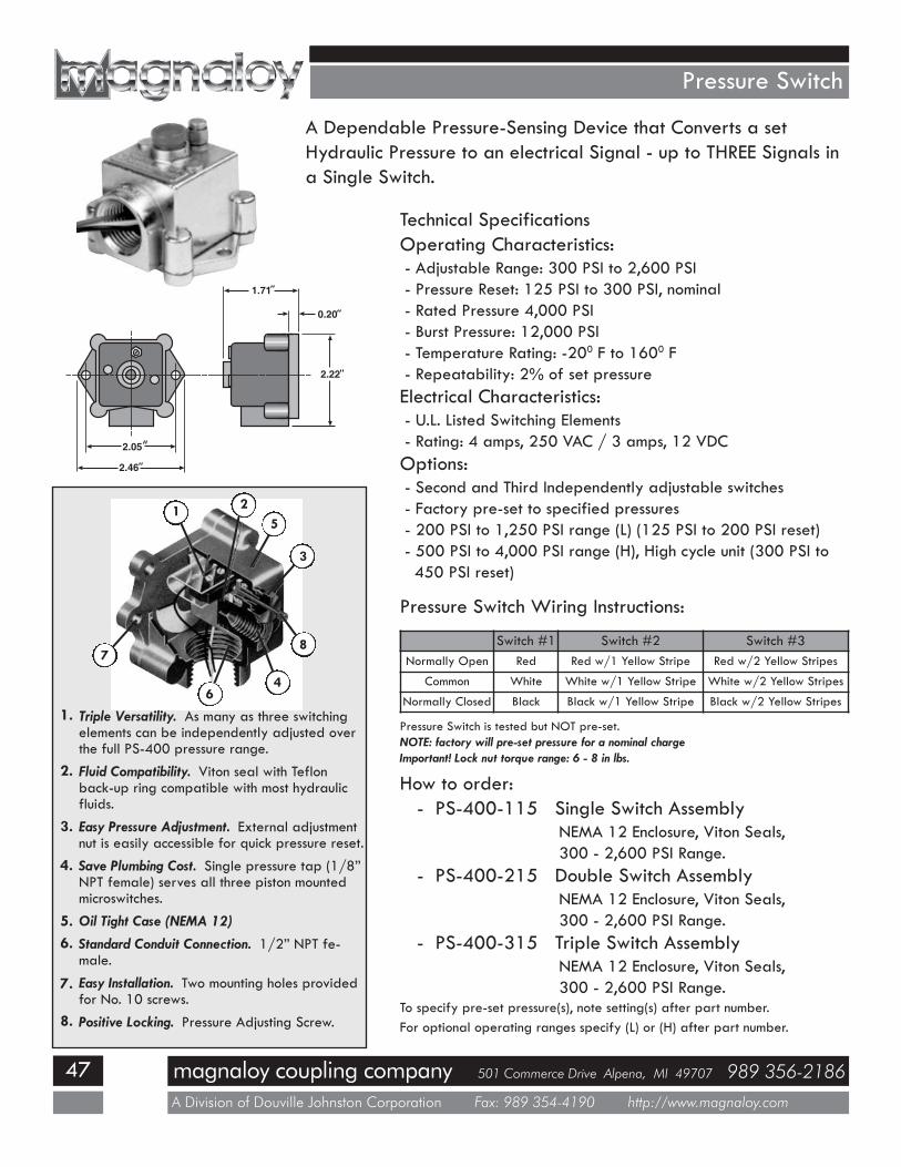
Pressure Switch
A Dependable Pressure-Sensing Device that Converts a setHydraulic Pressure to an electrical Signal - up to THREE Signals ina Single Switch.
Technical SpecificationsOperating Characteristics:- Adjustable Range: 300 PSI to 2,600 PSI- Pressure Reset: 125 PSI to 300 PSI, nominal- Rated Pressure 4,000 PSI- Burst Pressure: 12,000 PSI- Temperature Rating: -200 F to 1600 F- Repeatability: 2% of set pressureElectrical Characteristics:- U.L. Listed Switching Elements- Rating: 4 amps, 250 VAC / 3 amps, 12 VDCOptions:- Second and Third Independently adjustable switches- Factory pre-set to specified pressures- 200 PSI to 1,250 PSI range (L) (125 PSI to 200 PSI reset)- 500 PSI to 4,000 PSI range (H), High cycle unit (300 PSI to450 PSI reset)
Pressure Switch Wiring Instructions:
Switch #1 Switch #2 Switch #3Normally Open Red Red w/1 Yellow Stripe Red w/2 Yellow Stripes
Common White White w/1 Yellow Stripe White w/2 Yellow Stripes
Normally Closed Black Black w/1 Yellow Stripe Black w/2 Yellow Stripes
Pressure Switch is tested but NOT pre-set.NOTE: factory will pre-set pressure for a nominal chargeImportant! Lock nut torque range: 6 - 8 in lbs.
How to order:- PS-400-115 Single Switch Assembly
NEMA 12 Enclosure, Viton Seals,300 - 2,600 PSI Range.
- PS-400-215 Double Switch AssemblyNEMA 12 Enclosure, Viton Seals,300 - 2,600 PSI Range.
- PS-400-315 Triple Switch AssemblyNEMA 12 Enclosure, Viton Seals,300 - 2,600 PSI Range.
To specify pre-set pressure(s), note setting(s) after part number.For optional operating ranges specify (L) or (H) after part number.
1.71
0.20
2.22
2.05
2.46
Triple Versatility. As many as three switchingelements can be independently adjusted overthe full PS-400 pressure range.Fluid Compatibility. Viton seal with Teflonback-up ring compatible with most hydraulicfluids.Easy Pressure Adjustment. External adjustmentnut is easily accessible for quick pressure reset.Save Plumbing Cost. Single pressure tap (1/8”NPT female) serves all three piston mountedmicroswitches.Oil Tight Case (NEMA 12)
Standard Conduit Connection. 1/2” NPT fe-male.Easy Installation. Two mounting holes providedfor No. 10 screws.Positive Locking. Pressure Adjusting Screw.
1.
2.
3.
4.
5.6.
7.
8.
1 2
4
8
5
6
7
3
magnaloy coupling company 501 Commerce Drive Alpena, MI 49707 989 356-2186
A Division of Douville Johnston Corporation Fax: 989 354-4190 http://www.magnaloy.com
48
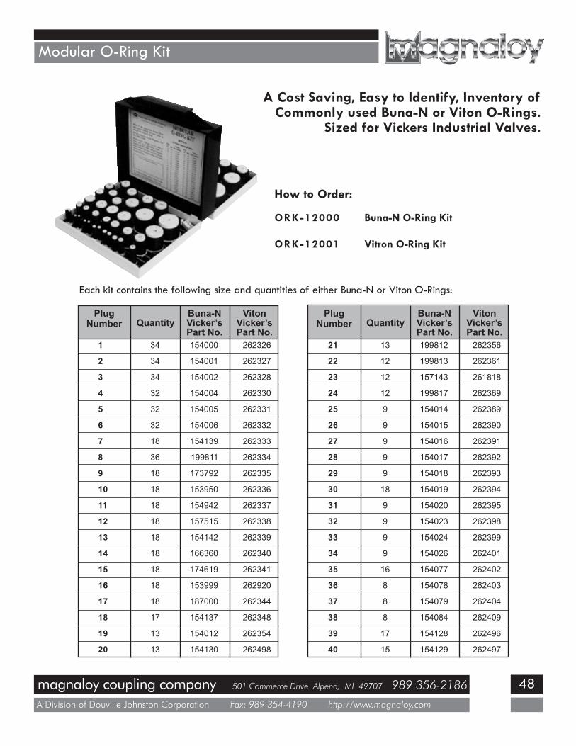
Modular O-Ring Kit
34
34
34
32
32
32
18
36
18
18
18
18
18
18
18
18
18
17
13
13
1
2
3
4
5
6
7
8
9
10
11
12
13
14
15
16
17
18
19
20
PlugNumber Quantity
154000
154001
154002
154004
154005
154006
154139
199811
173792
153950
154942
157515
154142
166360
174619
153999
187000
154137
154012
154130
262326
262327
262328
262330
262331
262332
262333
262334
262335
262336
262337
262338
262339
262340
262341
262920
262344
262348
262354
262498
Buna-NVicker’sPart No.
VitonVicker’sPart No.
13
12
12
12
9
9
9
9
9
18
9
9
9
9
16
8
8
8
17
15
21
22
23
24
25
26
27
28
29
30
31
32
33
34
35
36
37
38
39
40
PlugNumber Quantity
199812
199813
157143
199817
154014
154015
154016
154017
154018
154019
154020
154023
154024
154026
154077
154078
154079
154084
154128
154129
262356
262361
261818
262369
262389
262390
262391
262392
262393
262394
262395
262398
262399
262401
262402
262403
262404
262409
262496
262497
Buna-NVicker’sPart No.
VitonVicker’sPart No.
A Cost Saving, Easy to Identify, Inventory ofCommonly used Buna-N or Viton O-Rings.
Sized for Vickers Industrial Valves.
Each kit contains the following size and quantities of either Buna-N or Viton O-Rings:
How to Order:
ORK-12000 Buna-N O-Ring Kit
ORK-12001 Vitron O-Ring Kit
magnaloy coupling company 501 Commerce Drive Alpena, MI 49707 989 356-2186
A Division of Douville Johnston Corporation Fax: 989 354-4190 http://www.magnaloy.com
49
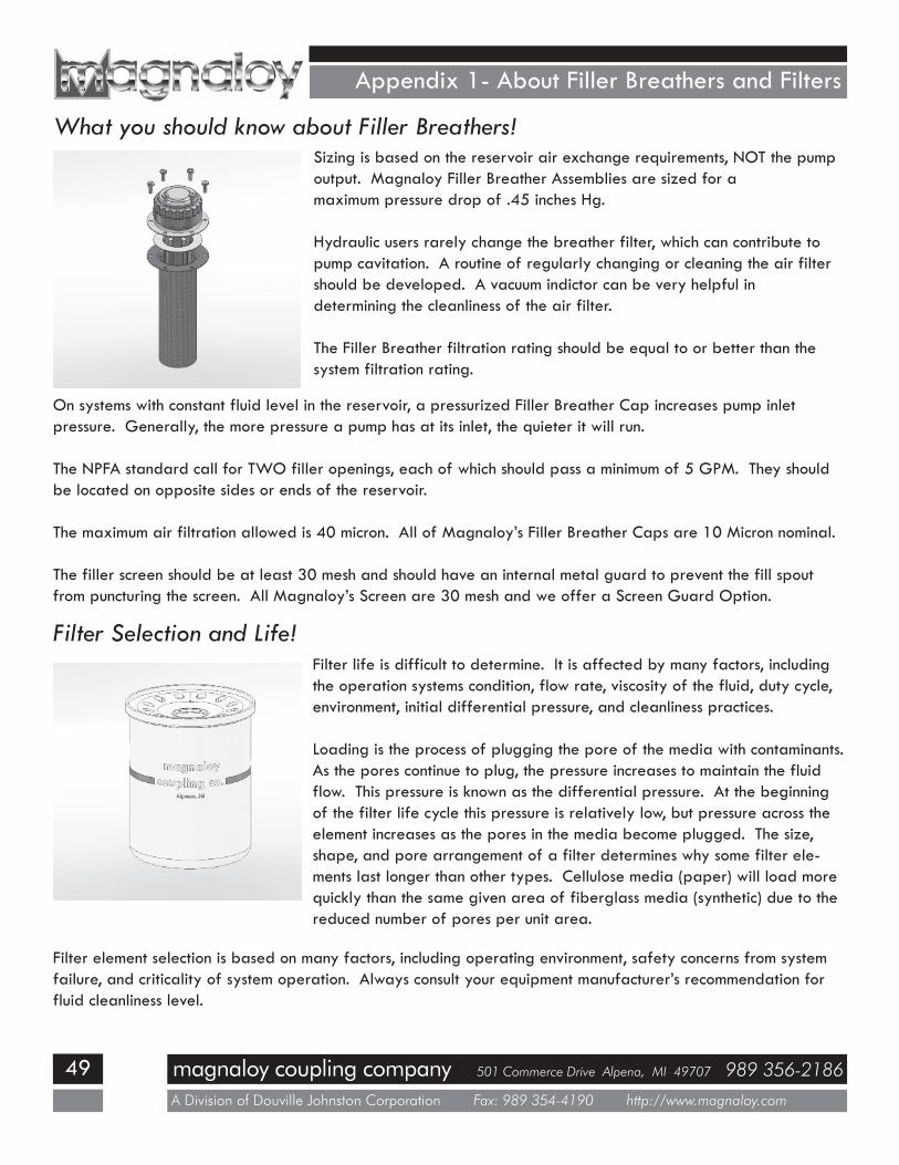
Appendix 1- About Filler Breathers and Filters
What you should know about Filler Breathers!Sizing is based on the reservoir air exchange requirements, NOT the pumpoutput. Magnaloy Filler Breather Assemblies are sized for amaximum pressure drop of .45 inches Hg.
Hydraulic users rarely change the breather filter, which can contribute topump cavitation. A routine of regularly changing or cleaning the air filtershould be developed. A vacuum indictor can be very helpful indetermining the cleanliness of the air filter.
The Filler Breather filtration rating should be equal to or better than thesystem filtration rating.
On systems with constant fluid level in the reservoir, a pressurized Filler Breather Cap increases pump inletpressure. Generally, the more pressure a pump has at its inlet, the quieter it will run.
The NPFA standard call for TWO filler openings, each of which should pass a minimum of 5 GPM. They shouldbe located on opposite sides or ends of the reservoir.
The maximum air filtration allowed is 40 micron. All of Magnaloy’s Filler Breather Caps are 10 Micron nominal.
The filler screen should be at least 30 mesh and should have an internal metal guard to prevent the fill spoutfrom puncturing the screen. All Magnaloy’s Screen are 30 mesh and we offer a Screen Guard Option.
Filter Selection and Life!Filter life is difficult to determine. It is affected by many factors, includingthe operation systems condition, flow rate, viscosity of the fluid, duty cycle,environment, initial differential pressure, and cleanliness practices.
Loading is the process of plugging the pore of the media with contaminants.As the pores continue to plug, the pressure increases to maintain the fluidflow. This pressure is known as the differential pressure. At the beginningof the filter life cycle this pressure is relatively low, but pressure across theelement increases as the pores in the media become plugged. The size,shape, and pore arrangement of a filter determines why some filter ele-ments last longer than other types. Cellulose media (paper) will load morequickly than the same given area of fiberglass media (synthetic) due to thereduced number of pores per unit area.
Filter element selection is based on many factors, including operating environment, safety concerns from systemfailure, and criticality of system operation. Always consult your equipment manufacturer’s recommendation forfluid cleanliness level.
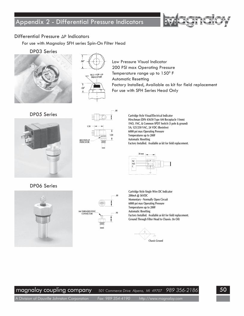
magnaloy coupling company 501 Commerce Drive Alpena, MI 49707 989 356-2186
A Division of Douville Johnston Corporation Fax: 989 354-4190 http://www.magnaloy.com
50
Appendix 2 - Differential Pressure Indicators
Differential Pressure ∆P IndicatorsFor use with Magnaloy SFH series Spin-On Filter Head
DP03 Series
Low Pressure Visual Indicator200 PSI max Operating PressureTemperature range up to 1500 FAutomatic ResettingFactory Installed, Available as kit for field replacementFor use with SFH Series Head Only
DP05 Series
DP06 Series
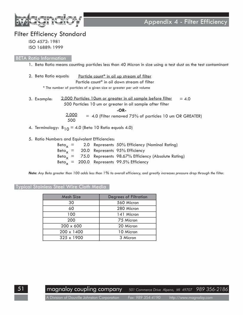
magnaloy coupling company 501 Commerce Drive Alpena, MI 49707 989 356-2186
A Division of Douville Johnston Corporation Fax: 989 354-4190 http://www.magnaloy.com
51
Appendix 4 - Filter Efficiency
Filter Efficiency StandardISO 4572: 1981ISO 16889: 1999
1. Beta Ratio means counting particles less than 40 Micron in size using a test dust as the test contaminant
2. Beta Ratio equals:
* The number of particles of a given size or greater per unit volume
3. Example: = 4.0
-OR-= 4.0 (Filter removed 75% of particles 10 um OR GREATER)
4. Terminology: B10 = 4.0 (Beta 10 Ratio equals 4.0)
5. Ratio Numbers and Equivalent Efficiencies:Betax = 2.0 Represents 50% Efficiency (Nominal Rating)Betax = 20.0 Represents 95% EfficiencyBetax = 75.0 Represents 98.67% Efficiency (Absolute Rating)Betax = 200.0 Represents 99.5% Efficiency
Note: Any Beta greater than 100 adds less than 1% to overall efficiency, and greatly increases pressure drop through the filter.
Particle count* in oil up stream of filterParticle count* in oil down stream of filter
2,000 Particles 10um or greater in oil sample before filter500 Particles 10 um or greater in oil sample after filter
2,000500
BETA Ratio Information
Typical Stainless Steel Wire Cloth Media
Mesh Size Degrees of Filtration30 560 Micron60 280 Micron100 141 Micron200 75 Micron
200 x 600 20 Micron200 x 1400 10 Micron325 x 1900 3 Micron
magnaloy coupling company 501 Commerce Drive Alpena, MI 49707 989 356-2186
A Division of Douville Johnston Corporation Fax: 989 354-4190 http://www.magnaloy.com
52
Appendix 5 Filter Selection
Filter Selection DataFluid Viscosity & Flow Capacity
The single most critical variable in determining the flow capacity of a filter is the viscosity of thefluid passing through it. Pressure drop ( ∆P ) produced by flow through a filter assembly is directlyproportional to the viscosity of the fluid being filtered. At any given flow rate, a lower viscosity fluidwill produce less pressure drop (and greater flow capacity) than that of a higher viscosity fluid.
Fluid Viscosity & TemperatureA fluids viscosity is governed by its temperature. As a fluid’s temperature increases, its viscositydecreases. Use a temperature versus viscosity chart to determine the viscosity of the fluid used inyour system at its normal operating temperature.
Estimating Pressure Drop ( ∆P )All pressure drop data found in this catalog is based on 150 SUS oil. If the fluid to be filtered inyour application has a viscosity of 150 SUS at the system’s normal operating temperature, pressuredrop values can be taken directly off the graphs. If the fluid’s viscosity is not 150 SUS, use theformula below to estimate the pressure drop.
Estimated Pressure Drop( ∆P ) through filter assembly = Pressure Drop Value
taken from graphX
Viscosity of Fluid atSystem Operating Temperature
150
Filtration Application GuidelinesSuction Strainers:
Maximum pressure drop : 1” HgMaximum line velocity: 5 feet per second
Suction Line Filters:Maximum pressure drop: No more than 50% of the Maximum allowable vacuum recommended by
the pump manufacturer (at normal operating temperature with a clean filter element).Maximum line velocity: 5 feet per second
Return Line Filters:Maximum pressure drop: No more than 50% of the filter by-pass valve setting at normal operating
temperature with a clean filter element.Maximum line velocity: 15 feet per secondA By-Pass Valve should ALWAYS be included on a Return Filter
Pressure Filters:Maximum pressure drop: No more than 50% of the filter by-pass valve setting at normal operating
temperature with a clean filter element.Maximum line velocity: 25 feet per second

magnaloy coupling company 501 Commerce Drive Alpena, MI 49707 989 356-2186
A Division of Douville Johnston Corporation Fax: 989 354-4190 http://www.magnaloy.com
53
Make the Connectionwith ......
Whatever your Fluid Power Unit needs,magnaloy has the productsto keep you connected.
Flexible Drive CouplingsTop-of-the-line magnesium couplingsare lighter, yet stronger than eithercast iron or aluminum. They alsooffer better corrosion resistanceand easier handling.
Pump/Motor MountsPrecision machined aluminum & custom
steel pump/motor mounts directly connectthe motor and pump while ensuring
accurate shaft alignment and enclosing thecoupling. Vertical and horizontal models
readily available from stock.
PM 90 CouplingsEconomical PM-90 Iron Powder
Couplings have long lastingnitrile, hytrel or urethane inserts.Double set screws give excellent
gripping power.
Magnaloy Hydraulic BarManifolds & AccessoriesComplete line of inline Bar Manifolds,Subplates, Cover Plates, Valve Adaptors,Integrated Circuit Manifolds, andAccessories to make the design andfabrication of Hydraulic Circuitry simpleand easy. Wide range of sizes include:D03, D05, D05H & D08 in aluminum andsteel with ports available in SAE, NPTF,BSPP, and BSPT styles. Custom design and fabrica-tion also available, consult factory.
Rod End CouplersTwo models of accurately machined high ten-
sile cylinder rod end alignmentcouplers offer 7o or 10o sphericaland 1/8” parallel misalignment
capabilities.
Magnaloy Reservoirs& Reservoir Accessories
Magnaloy offers a complete line of standardreservoirs and reservoir
accessories. In addition, we offercustom reservoir fabrication to meet
our customer specific needs.Reservoirs accessories such as Clean Out Cov-ers and SAE Couplings are available for the
“do-it-yourself”reservoir manufacturer
For a Free Catalog of anyof these fine products call
or visit us on-line.
AccessoriesFiller Breather Adaptors, Filler Breathers,Reservoir Flanges, Suction Strainers,Gauge Isolators, Liquid Level Gauges,Modular O-Ring Kits.
Magnaloy Pressure SwitchPressure Sensing switch capable of sensing upto three (3) separate pressures. Each sensoris externally independently adjustable from200 to 4000 psi. Viton seals provide wide
fluid compatibility range.