magduo rep i18 - scolmore
TRANSCRIPT
MAGDUO REP I18

MAGDUO Repeater Panel Engineering and Commissioning Manual
26-1652-01 26-1662-01
ESP’s policy is one of continual improvement and the right to change a specification at any time without notice is reserved. Whilst every care has been taken to ensure that the contents of this document are correct at time of publication, ESP shall be under no liability whatsoever in respect of such contents.
Due to the complexity and inherent importance of a life risk type system, training on this equipment is essential and commissioning should only be carried out by competent persons. ESP cannot guarantee the operation of any equipment unless all documented instructions are complied with, without variation. E&OE.

MAGDUO Repeater Panel Engineering and Commissioning Manual
3
Contents Introduction ........................................................................................................................................................... 5
System Design ...................................................................................................................................................... 5 Equipment Guarantee .................................................................................................................................. 5 Anti-Static Handling Guidelines .................................................................................................................... 5 Warning ........................................................................................................................................................ 6 EMC .............................................................................................................................................................. 6
The MAGDUOSystem ........................................................................................................................................... 6
Repeater Panel, Remote Display Unit (RDU) ..................................................................................................... 6
Mounting the Repeater Panel .............................................................................................................................. 7 Physical Dimensions .................................................................................................................................... 9
General Assembly .............................................................................................................................................. 10 Ribbon Cable Connection .......................................................................................................................... 10 Fixing Front Panel ...................................................................................................................................... 10
Installation and Commissioning ....................................................................................................................... 11 Topology & Cabling .................................................................................................................................... 11 Maximum Cable Lengths ............................................................................................................................ 11 Power Supply & Connections ..................................................................................................................... 12
Power Connection Table .................................................................................................................. 12 Current Drawn by Single Repeater @ 24.0V DC ............................................................................. 12 Separate Power Supply Requirements ............................................................................................ 12 Repeater Back Board Power supply connections ............................................................................ 12
Peripheral Bus Connections ....................................................................................................................... 13 Peripheral Bus Connection Table .................................................................................................... 13 Example of Panel Peripheral Bus Connections Showing EOL Resistor .......................................... 13 Repeater Back Board Peripheral Bus connections .......................................................................... 13
Main Control Panel Peripheral Bus Settings .............................................................................................. 14 Repeater Panel Settings ............................................................................................................................ 14
LCD Contrast.................................................................................................................................... 14 Setting Repeater Number ................................................................................................................ 15 Repeater Buzzer .............................................................................................................................. 15 Powering Up ..................................................................................................................................... 15
Commissioning ........................................................................................................................................... 16 Fault finding ................................................................................................................................................ 16
General Operation of Repeater Panel ............................................................................................................... 17 Control Panel Front .................................................................................................................................... 17 LED Indication ............................................................................................................................................ 17 Fire Alarm Controls..................................................................................................................................... 18 System Controls ......................................................................................................................................... 18 Access Levels ............................................................................................................................................. 18
Access Level 1 (Normal): Controls Enabled LED off ....................................................................... 19 Access Level 2 (user): Controls Enabled LED on ............................................................................ 19
End User Training ............................................................................................................................................... 20
Maintenance ........................................................................................................................................................ 20

MAGDUO Repeater Panel Engineering and Commissioning Manual
26-1652-01 26-1662-01
Technical Data .................................................................................................................................................... 20
Repeater Panel Specification ............................................................................................................................ 20
Fire Alarm System Notice .................................................................................................................................. 21 To Enable the Control Panel Keys ............................................................................................................. 21 To Manually Operate the Fire Alarm Sounders .......................................................................................... 21 Following a Fire Alarm Operation ............................................................................................................... 21 Following a Fault Condition ........................................................................................................................ 21
Important Notes .................................................................................................................................................. 22
Fire Alarm User Notice ....................................................................................................................................... 23
Technical Support .................................................................................................... Error! Bookmark not defined.

MAGDUO Repeater Panel Engineering and Commissioning Manual
5
Introduction
This Manual is intended as a guide to the engineering and commissioning principles of the MAGDUO Repeater Panel and covers the system hardware information only. Due to the complexity and inherent importance of a system covering a ‘Life Protection Risk’, training on this equipment is essential and commissioning should only be carried out by competent and approved persons. For further details of the availability of commissioning services, please contact your supplier.
System Design
This document does not cover Fire Alarm system design and a basic understanding is assumed. A knowledge of BS5839: Pt 1: 2017: Fire Detection and Alarm Systems for Buildings is essential. It is strongly recommended that a suitably qualified and competent person is consulted in connection with the Fire Alarm System design and that the entire system is commissioned in accordance with the current national standards and specifications.
Equipment Guarantee
The equipment carries no warranty unless the system is installed, commissioned and serviced in accordance with this manual and the relevant standards by a suitably qualified and competent person or organisation
Anti-Static Handling Guidelines
Immediately prior to handling any PCBs or other static sensitive devices, it is essential to ensure that a personal connection to earth is made with an anti-static wrist-strap or similar apparatus. Always handle PCBs by their sides and avoid touching any components. PCBs should also be stored in a clean dry place, which is free from vibration, dust and excessive heat and is protected from mechanical damage.
!
!
!

MAGDUO Repeater Panel Engineering and Commissioning Manual
26-1652-01 26-1662-01
Warning Do not attempt to install this equipment until you have fully read and understood this manual.
Failure to do so may result in damage to the equipment and could invalidate the warranty. Technical support will not be available if the instruction manual has not been read and understood. Please have this instruction manual available whenever you call for technical support.
EMC This equipment when installed is subject to the EMC directive 2004/108/EC. It is also subject to UK Statutory Instrument 2006 No. 3418.
To maintain EMC compliance, this system must be installed as defined within this manual. Any deviation from this renders the installer liable for any EMC problems that may occur either to the equipment or to any other equipment affected by the installation.
The MAGDUO System
The MAGDUO system is an intelligent ‘2-wire’ system utilising a conventional type cabling format. The system is classed as ‘Analogue non-addressable’ due to the architecture used within the design. All field devices including sounders can be connected to the zone via a common 2-core screened cable. The devices communicate with the control panel using the ‘MAGDUO’ data protocol.
Repeater Panel, Remote Display Unit (RDU) The MAGDUO repeater panel is smaller than the MAGDUO control panel. It does not itself connect to or control detection devices. Instead, it connects to a control panel and reports events which occur on the control panel. It can also perform system controls over the network (i.e. Silence Alarms, Reset, Sound Alarms & Silence Buzzer). A maximum of 8 repeater panels can be connected to a single control panel. The maximum cable length from the control panel to a repeater is 500 metres. If 8 repeaters are used they must all be within the maximum 500 metres cable length. All external connections are made on the back board. The Ext Switches on the back board are not currently used and are for a future development.
!
!

MAGDUO Repeater Panel Engineering and Commissioning Manual
7
Mounting the Repeater Panel
First identify the proposed location for the repeater panel. Ensure that the repeater panel will be easily accessible and that account is taken of any subsequent work that may affect access. The repeater panel should be located at an access point to a building which is not covered by the main panel. Repeaters can also be located in other buildings which are connected to the main fire alarm panel. It should be mounted on a flat, vertical wall at a height where the indicators may be seen without difficulty. Do not locate the repeater panel at high level where stepladders or other access equipment may be required, in spaces with restricted access, or in a position that may require access panels to be removed. Do not locate the repeater panel where extremes of temperature or humidity may occur i.e. close to a heat source, or where there is any possibility of condensation or water ingress. Like all electronic equipment, the repeater panel may be affected by extreme environmental conditions. The position selected for its installation should therefore be clean and dry, not subjected to high levels of vibration or shock and at least 2 metres away from any pager or radio transmitting equipment. Ambient temperatures should be within the range given within the Technical Data section, e.g. not directly over a radiator or heater. In common with all microprocessor-controlled panels, the repeater panel may operate erratically or may be damaged if subjected to lightning induced transients. Proper earth/ground connections will greatly reduce susceptibility to this problem.

MAGDUO Repeater Panel Engineering and Commissioning Manual
26-1652-01 26-1662-01

MAGDUO Repeater Panel Engineering and Commissioning Manual
9
Physical Dimensions

MAGDUO Repeater Panel Engineering and Commissioning Manual
26-1652-01 26-1662-01
General Assembly
Ribbon Cable Connection
Fixing Front Panel

MAGDUO Repeater Panel Engineering and Commissioning Manual
11
Installation and Commissioning
Topology & Cabling
All system wiring should be installed to comply with BS 5839: Pt 1: 2017 and BS 7671 (wiring regulations) and any other standards relevant to the area or type of installation. A cable complying with the BS 5839: Pt 1: 2017 Category 1 (cables required to operate for prolonged periods during fire conditions) is required. This must be a 2-core 1.5mm2 screened fire resistant cable (i.e. FP200, Firetuff, Firecell, Lifeline or equivalent). In order to protect against possible data corruption it is important to ensure the following points are adhered to:
1. The cable screen must not be connected to earth/ground at any point other than the control panel (at the SCRN terminal provided, not at any earthing point). Do not connect the screen to a metal back box.
2. The cable screen continuity must be maintained at every point of the circuit, using the terminals provided or a suitable connection block.
3. Do not use a 4-core cable as a 24v supply and communications, due to the possibility of data corruption. It is essential that two 2-core screened cables are used, one for the 24V DC supply and the other for communications.
Maximum Cable Lengths The maximum total cable length from the control panel to a repeater is 500 metres. Up to 8 repeaters can be used but they must all be within the maximum 500 metres cable length.
Refer to power supply and peripheral bus connections for further details.

MAGDUO Repeater Panel Engineering and Commissioning Manual
26-1652-01 26-1662-01
Power Supply & Connections
24V DC Power is provided from the control panel via Aux+ and Aux-. 2-core 1.5mm2 screened fire resistant cable (i.e. FP200, Firetuff, Firecell, Lifeline or equivalent) cable should be used for the 24V power to the repeater and connected to the back board. The maximum total cable length from the control panel to a repeater is 500 metres. Up to 8 repeaters can be used but they must all be within the maximum 500 metres cable length and are wired +24v to +24V, 0V to 0V, Screen to Screen and so on up to the maximum of 8 repeaters.
Power Connection Table
Control panel First Repeater panel
Second Repeater panel
Aux+ +24V +24V
Aux- 0V 0V
SCRN Screen Screen
When powering a repeater from the panel the extra current will reduce the battery backup run time and has to be allowed for in the battery calculations.
Current Drawn by Single Repeater @ 24.0V DC
Quiescent (default screen no back light) 16.0mA
Controls enabled, back light on 50.0mA
Separate Power Supply Requirements The repeater can be powered by a separate 24v EN-54 power supply if required. The repeater working voltage range is between 21V DC to 32V DC with a maximum current of 50.0mA.
Repeater Back Board Power supply connections

MAGDUO Repeater Panel Engineering and Commissioning Manual
13
Peripheral Bus Connections Communications between the panel and repeater is via a multi-drop RS-485 Peripheral Bus. 2-core 1.5mm2 screened fire resistant cable ((i.e. FP200, FP200, Firetuff, Firecell, Lifeline or equivalent) cable should be used for communications to the repeater and connected to the back board. The maximum total cable length from the control panel to a repeater is 500 metres. Up to 8 repeaters can be used but they must all be within the maximum 500 metres cable length and are wired A to A, B to B, Screen to Screen and so on up to the maximum of 8 repeaters. The peripheral bus must be run from the panel to the first repeater then the second repeater and so on; the peripheral bus must not be spurred from one point.
Peripheral Bus Connection Table Control panel First Repeater
panel Second
Repeater panel NET A A A NET B B B SCRN Screen Screen
There are two sets of peripheral bus connections on the panel. These are linked in the panel so either set can be used. A 120Ω Smoothing resistor must also be fitted across NET A & NET B at the panel.
Example of Panel Peripheral Bus Connections Showing smoothing Resistor
On the repeater a 120Ω Smoothing resistor must also be fitted across A and B but only on the last repeater on the network.
Repeater Back Board Peripheral Bus connections
MAGDUO Repeater Panel Engineering and Commissioning Manual
26-1652-01 26-1662-01
Main Control Panel Peripheral Bus Settings
NOTE: The main control panel should be set to a number in the range of 10 to 99 when using repeaters. This is done by logging onto Engineers Mode and selecting option 9 Panel Details, then select option 4 PNL Identification, then option 1 Panel Number. The write Enable switch will need to be on for changes to take place.
To setup the main control panel to use repeaters, log into Engineers Mode and select Option 3 Enable / Disable, then option 5 peripheral bus and set the peripheral bus to ON. From the main Engineers Menu select option 11 Peripheral Bus, within this select: Option 1 PB RDU Supervise. In this option there is a list of 1 – 8 repeaters, (RDUs). Enable the repeater(s), (RDUs) that are being used and are connected to the panel. This will enable the panel to monitor the repeaters and report them as missing if there is a cable break or loss of communications.
When this is done press ESC to go back into option 11 Peripheral Bus. The main control panel should now be setup for the repeater(s). Note: If RDU addresses are enabled that are not on the network the panel will report them as “Missing”.
Repeater Panel Settings
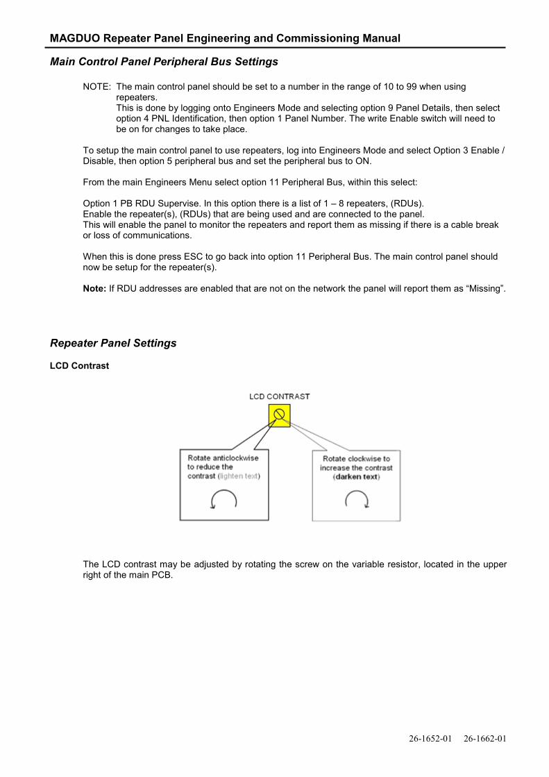
LCD Contrast
The LCD contrast may be adjusted by rotating the screw on the variable resistor, located in the upper right of the main PCB.

MAGDUO Repeater Panel Engineering and Commissioning Manual
15
Setting Repeater Number Each repeater has to be set with a unique number address in the range 1 – 8, the default number is 1. If more than one repeater is used on a single panel the repeater numbers will need to be changed, this is done using DIL switches A0 to A2 located next to the buzzer. Note: The DIL switches are only read on power up. The repeater must be powered down and back up again for changes to take effect. Address settings
A0 (1) A1 (2) A2 (3) Repeater Address
Off Off Off 1 On Off Off 2 Off On Off 3 On On Off 4 Off Off On 5 On Off On 6 Off On On 7 On On On 8
Repeater Buzzer The local repeater internal buzzer can be switched off using DIL switch SP1 (4) on the bank of switches located next to the buzzer.
SP1 (4) set to On = buzzer on SP1 (4) set to Off = buzzer off
This setting only affects the local buzzer and has no effect on the panel buzzer or other repeaters on network. Note: The DIL switches are only read on power up. The repeater must be powered down and back up again for changes to take effect.
Powering Up Having connected the power supply and peripheral bus to the repeater as described above. Power up the repeater, the LEDs will flash and the Display will show a default screen:
Then after a short period of time the display will show the same date and time as displayed on the main control panel it is connected to:
NOTE: If the default screen on the main control panel is changed the panel must be powered down and back up again with the repeater connected in order to update the default screen on the repeater.
00/00/00 00:00 NORM
Turn Key / Press Enter
23/07/13 14:35 NORM
Turn Key / Press Enter
MAGDUO Repeater Panel Engineering and Commissioning Manual
26-1652-01 26-1662-01
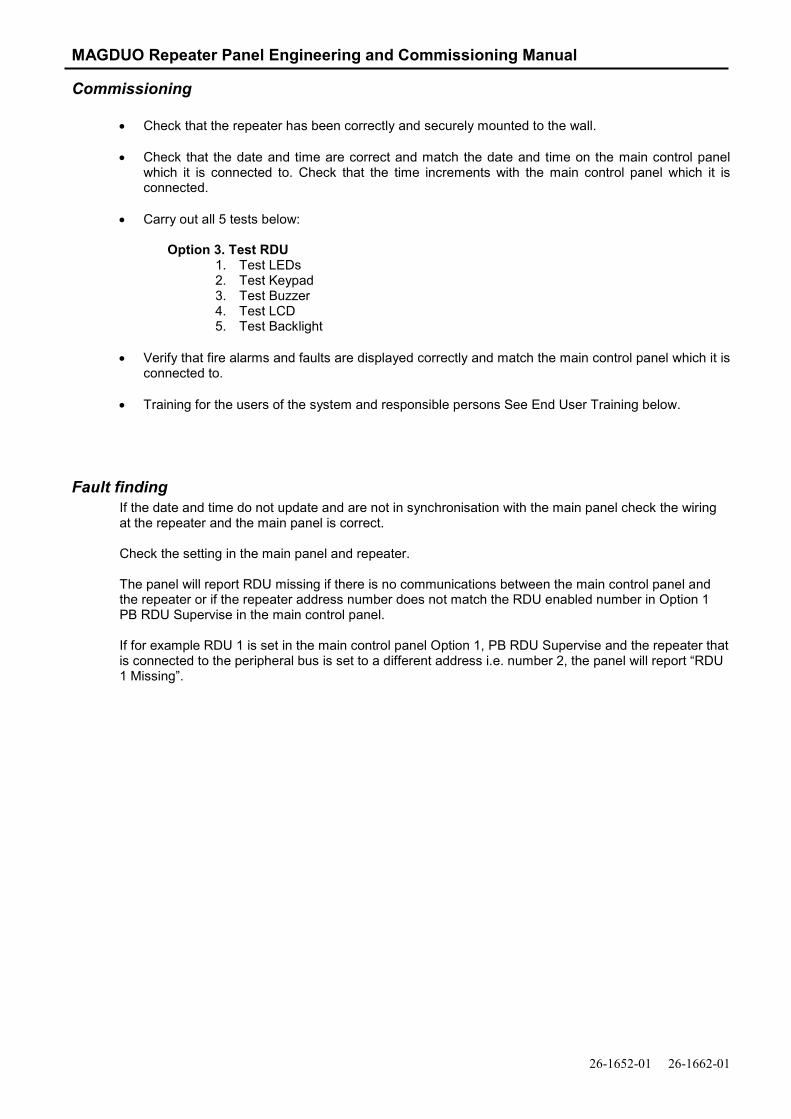
Commissioning
• Check that the repeater has been correctly and securely mounted to the wall.
• Check that the date and time are correct and match the date and time on the main control panel which it is connected to. Check that the time increments with the main control panel which it is connected.
• Carry out all 5 tests below:
Option 3. Test RDU
1. Test LEDs 2. Test Keypad 3. Test Buzzer 4. Test LCD 5. Test Backlight
• Verify that fire alarms and faults are displayed correctly and match the main control panel which it is
connected to.
• Training for the users of the system and responsible persons See End User Training below.
Fault finding If the date and time do not update and are not in synchronisation with the main panel check the wiring at the repeater and the main panel is correct. Check the setting in the main panel and repeater. The panel will report RDU missing if there is no communications between the main control panel and the repeater or if the repeater address number does not match the RDU enabled number in Option 1 PB RDU Supervise in the main control panel. If for example RDU 1 is set in the main control panel Option 1, PB RDU Supervise and the repeater that is connected to the peripheral bus is set to a different address i.e. number 2, the panel will report “RDU 1 Missing”.

MAGDUO Repeater Panel Engineering and Commissioning Manual
17
General Operation of Repeater Panel
Control Panel Front
LED Indication
The operation of the LED indication on the front of the repeater panel is described below. The LED indication on the repeater panel can also be confirmed by checking the message displayed in the repeater information screen or by accessing the relevant event log from the repeater menu.
Description
Colour State Reason
FIRE Red Continuous The control panel is in the fire state. Display will show the zone of origin.
FAULT
Yellow Continuous The control panel is in the fault state. Display will show the origin.
DISABLED
Yellow Continuous This indicates that a disablement action is in place.
TEST
Yellow Continuous This indicates that a test routine is in place.
POWER Green Continuous
This indicates that power is being supplied to the panel.
General Indication LEDs Repeater Information Screen
Fire Alarm Controls / Controls Enabled Keyswitch
System Controls

MAGDUO Repeater Panel Engineering and Commissioning Manual
26-1652-01 26-1662-01
Fire Alarm Controls
The main Fire Alarm Controls may be enabled by turning the key switch to the controls enabled position to go from access level 1 to access level 2.
System Controls
The menus may be navigated to by using the UP / DOWN keys to move the required selection to the top and pressing ENTER to select the chosen one.
In the example below pressing enter will select current faults.
Press the ESC key to exit to the previous menu.
Access Levels The menu system is divided into two access levels in order to restrict access to those who require it. For simple indication, the status of the Controls Enabled light will show the level selected as follows;
Access Level Description Controls Enabled LED Key Operation
1 – NORM Normal OFF N/A 2 – 1111 User ON YES
Access to the Controls requires the operation of the enable controls key, Access Level 2 (User) in order to protect against unauthorised access to the system.
Current Events 2. Current Faults 3. Current Disables Select / /Enter / ESC

MAGDUO Repeater Panel Engineering and Commissioning Manual
19
Access Level 1 (Normal): Controls Enabled LED off Note: When in the normal mode, the quiescent screen will automatically change to display any fires or faults
on the system.
Pressing the enter button when in level 1 will show the Current Events Menus and may be scrolled through by pressing the UP and DOWN keys. Press the ESC key to exit the menu. Option 1. Current Fires Option 2. Current Faults Option 3. Current Disables Option 4. Current warnings Events are displayed in text format and may be scrolled through by pressing the UP and DOWN keys. Press the ESC key to exit the menu.
Access Level 2 (user): Controls Enabled LED on
Pressing the enter button when in level 2 will show the Main Menu and may be scrolled through by pressing the UP and DOWN keys. Press the ESC key to exit the menu.
Option 1. Current Events 1. Current Fires
2. Current Faults 3. Current Disables 4. Current warnings
Option 2. Test Repeater
1. Test LEDs 2. Test Keypad 3. Test Buzzer 4. Test LCD 5. Test Backlight
Option 3. Repeater Details
1. Buzzer 2. Software Version 3. Repeater Panel # 4. Display Baudrate

MAGDUO Repeater Panel Engineering and Commissioning Manual
26-1652-01 26-1662-01
End User Training
A Fire Alarm System is of little use if the end user and/or the responsible persons who will be present in the building do not know how to operate and respond to the system. It is therefore essential that commissioning includes training for the users of the system and responsible persons.
User instructions and a Zone Chart should be left adjacent to the control panel. As access to the system must be controlled by responsible persons, it would be unusual to display the access codes on this notice. These codes must however be available for the responsible persons, so ensure that they know and record them in a secure place.
The MAGDUO Repeater User Guide should be explained and left with the responsible person on site, for storage in an accessible and known location, in order that the responsible person and the service engineer may keep information records up to date.
A single page user instruction sheet is included at the end of this manual. A copy of this should be mounted adjacent to the control panel.
Maintenance
The repeater panel does not require user maintenance, however periodic functional checks should be carried out by an engineer or responsible persons.
Technical Data
Repeater Panel Specification
Dimensions (mm) 250 x 140 x 85
Weight 650 grams
Construction UL94-V0 rated ABS
Cable Entry 6 x 20mm knockouts, 4 x double 20mm knockouts
Cable type 2 core 1.5mm2 screened fire rated cable
Operating voltage Nominal 24V DC (Range 21 - 32V DC)
Operating current Quiescent @ 24V DC 16 mA (back light off)
Operating current Max @ 24V DC 50 mA (controls enabled, back light on)
Communications Multi-drop RS-485
Total peripheral bus length 500m (max)
IP rating 20 Maximum number of repeaters per control panel 8
Operating temperature 5OC to 50OC

MAGDUO Repeater Panel Engineering and Commissioning Manual
21
Fire Alarm System Notice
To Enable the Control Panel Keys
You may gain access to the fire alarm controls by inserting the key turning ¼ turn. The ‘Controls Enabled’ LED should then be illuminated.
To disable the control panel keys, turn the key switch off. When disabled, the ‘Controls Enabled’ LED should then be extinguished.
To prevent unauthorised operation, the controls should be kept disabled and the key kept secure under the control of the responsible person.
To Manually Operate the Fire Alarm Sounders
Enable the controls and then press ‘SOUND ALARMS’.
To silence the alarm sounders press ‘SILENCE ALARMS’.
Following a Fire Alarm Operation
The red ‘FIRE’ LED will illuminate. The fire alarms and the internal buzzer will operate as programmed. Take appropriate action as defined by the emergency plan for the premises. To silence the alarm press ‘SILENCE ALARMS’, then establish the cause of the alarm and enter the details in the log book.
Reset any Manual Call Points which may have been operated, or if a detector has been operated be sure that the cause of the alarm has been removed, before resetting the system by pressing ‘RESET SYSTEM’.
Following a Fault Condition
The fault LED will illuminate. The internal buzzer will sound. To mute the internal buzzer press ‘SILENCE BUZZER’. Investigate and rectify the appropriate fault (competent persons). Once the fault has been rectified the fault indication will clear automatically.
MAGDUO Repeater Panel Engineering and Commissioning Manual
26-1652-01 26-1662-01
Important Notes
FIRE ALARM COMPANY: ______________________________________________________________________ ADDRESS: __________________________________________________________________________________ For Service Phone: _____________________ (During Working Hours) _____________________(Out of Working Hours)
FIRE ALARM COMPANY:
ADDRESS:
FOR SERVICE CALL: (Working hours) (Call Out)

MAGDUO Repeater Panel Engineering and Commissioning Manual
23
Fire Alarm User Notice
Note
The Fire alarm system installed in this building has ‘Alarm Confirmation’ technology to help eliminate false alarms.
Please read and understand the following information in order to make the most use of the system.
Operation
When the detector within your area activates it will initially only operate the sounders within your own area for a predetermined ‘Confirmation’ time. At the end of the ‘Confirmation’ time the system will check the detector again to see if the activation has cleared. If so, the sounders will silence and no further action need be taken. If, however, the detector is still activated, the entire system will go into alarm, operating all the sounders on the system.
Action Required
If you think that you may have accidentally set off the fire alarms, then check the following: If the fire alarm within your area only is sounding, then check your own area for the cause of the alarm. If this proves to be a false alarm due to dust, cooking fumes, steam, cigarette smoke, etc, then clear the smoke from the area in order to allow the system to reset itself after a few minutes. If this happens then no further action is required. If the fire alarms in the communal areas are also sounding, then follow the building’s fire procedures for evacuation. If you discover a genuine fire, then follow the building’s fire procedures for evacuation, activating the nearest Fire Alarm manual call point on the way out if the alarms are not already sounding.
Do not attempt to put out the fire unless it is safe to do so.
Further Information
Further information will be located adjacent to the Main Fire Alarm Control Panel, or may be obtained from either the person responsible for building maintenance or from the Fire Alarm Company responsible for maintaining the Fire Alarm System.

MAGDUO Repeater Panel Engineering and Commissioning Manual
26-1652-01 26-1662-01
Elite Security Products LTD
Unit 7 Target Park, Shawbank Road, Lakeside, Redditch, B98 8YN England
13 DoP-MAGDUOREP-01
Technical Support Due to the complexity and inherent importance of a life risk type system, training on this equipment is essential, and commissioning should only be carried out by competent persons. ESP’s policy is one of continual improvement and the right to change a specification at any time without notice is reserved. Whilst every care has been taken to ensure that the contents of this document are correct at time of publication, ESP shall be under no liability whatsoever in respect of such contents. E&OE. www.espuk.com

MAGDUO Repeater Panel Engineering and Commissioning Manual
25