macro and micro applications for fibre lasers in … · 2016-01-04 · macro and micro applications...
TRANSCRIPT
MACRO AND MICRO APPLICATIONS FOR FIBRE LASERS IN LASER MATERIAL PROCESSING OF AEROSPACE COMPOSITE MATERIAL
Paper (610)
Paul French1, Mo Naeem2, Emily Leach3, John Clowes4, Martin Sharp1
1Liverpool John Moores University, General Engineering Research Institute, James Parson Building, Byrom St, Liverpool, Merseyside, L3 3AF, Great Britain
2SPI Lasers, 6 Wellington Park, Hedge End, Southampton, Hampshire, SO30 2QU, Great Britain 3Wirral Grammar School for Girls, Health Rd, Bebington, Wirral, CH63 3AF.Great Britain
4Fianium Ltd, 20 Compass Point, Ensign Way, Southampton, SO31 4RA, Great Britain
Abstract
The aerospace industry is showing an increased interest in composite materials. The A380, A350XWB and the Boeing 787 are using or plan to use a large percentage of composite material in their construction. Aerospace companies at present are favouring water jet machining for material processing of composites, i.e. cutting, milling. We have investigated the use of fibre lasers in processing both carbon and glass fibre composites. We have used two different types of laser, the first a 200W fibre laser system from SPI Lasers to investigate laser cutting and milling. The second was a picosecond pulsed fibre laser system from Fianium investigated a micromachining application. Our results show that by careful control of processing parameters laser cutting of both thin and thicker composite material is possible and our micromachining experiments showed that it is possible to micro-texture the surface of carbon composite and modify the surface wettability to promote increased bond strength in a composite joint.
Introduction
Carbon fibre reinforced plastic (CFRP) composites have attracted considerable interest from a number of different industrial sectors but primary from the aerospace sector. Aircraft manufacturers, such as Boeing and Airbus, see the potential benefits of using CFRP composites due to its superior properties over its metallic alternatives. Their low density, high strength and high stiffness to weight ratio make them a suitable candidate for many aerospace applications. These new aerospace materials require processing i.e. cutting, drilling and milling normally using traditional machine tools. Recently aerospace companies have been investing in water jet technology for cutting CFRP composites. Water jet can give a high quality cut but
this has associated problems of causing delamination and requires a pilot hole to be drilled mechanically if the cutting process starts anywhere other than at the edge of the sheet. Other potential issues with water jet cutting are disposal of waste cutting products. The use of lasers for cutting of CFRP composites has yet to be exploited by the aerospace industry.
A possibly new and novel application for lasers in the aerospace industry is a micromachining application of microtexturing. With the increased use of CFRP composites there has been an increased use of adhesive joining technology. Prior to applying the adhesive to the surfaces of the composite components the surface is currently mechanically abraded using an abrasive disk. This roughens the surface of the composite and increases the surface energy of the surface increasing the wettability of the surface. This improves the spreading of the adhesive and increases the strength of the joint.
Laser cutting
Pervious work on laser processing of composite materials can be split into two main themes, firstly laser drilling with a Nd-YAG laser and secondly laser cutting with a CO2 laser system. One exception to this is Galantucci [1] who investigated laser cutting of a thermoset polyester resin with an excimer laser due to its importance as a matrix material for plastic composites. Galantucci derived a photo ablation model that predicted the cross sectional profile of the cut. Caprino and Tagliaferri [2] derived a one dimensional model that predicted the maximum cutting speed for cutting CFRP as well as other composite materials such as glass fibre reinforced plastic and aramidic fibre reinforced plastic with a CO2 laser. Two CO2 laser systems were used in experimental work to verify the model. A 0.5 kW Valfivre L500 and a 2.0 kW BOC system. The material thickness varied from 1.5 mm to 4.5 mm. The model gave good agreement with the
289
three different composites and was expected to work well for high power density and feed rates. Cenna and Mathew [3] developed a model than looked at various parameters in laser cutting, material removal rate, kerf width kerf angle and energy transmitted through the cut kerf. The laser used to verify the model was once again a CO2 laser, a 1.5 kW PRC. The developed model using the energy balance equation successfully predicted the above parameters for aramidic fibre reinforced plastic but underestimated the results for glass fibre reinforced plastics. Shanmugam et al [4] compared laser cutting with plain water jet and abrasive water jet cutting. The experiments determined the kerf angle and the Ra of the cut surface. A CO2 laser was used during the experiments but the make or material thickness was used in the experiment was not given. The paper concluded that abrasive water jet cutting was the preferred cutting method. This could well be true for thick CFRP, 10 mm or greater but this threshold has yet to be determined. Cheng et al [5] and Voisey et al [6] identified an interesting phenomena when laser drilling. They observed that depending on the type of fibre used in the composite it could have a tendency to swell during laser drilling. Voisey determined that there was a possible link to impurities contained within the fibre and the rapid temperature gradient induced by laser processing. The high pressure gases act as a driving force leaving the laser processed composite structure more open after laser drilling.
Laser Surface Texturing
There are few papers looking at using lasers in surface texturing application, especially with respect to the adhesive bonding of composites. Molitor and Young [7] investigated the use of excimer lasers, KrF, ArF and XeCl, in laser texturing titanium prior to testing the treated surface in a single lap shear joint tensile test. The joint was a hybrid titanium / glass fibre reinforced composite laminate. The surface of the composite was not laser surface textured. Their results showed a significant increase in shear strength of 23%.
An important finding from this investigation was that the contact angle reverted back to its original value if the surface was left exposed to the environment.
Experimental Set-up
Two fibre laser systems were used in this investigation.
An SPI Lasers fibre laser, used on both the laser cutting and the micromachining surface texturing experiments. The Fianium FemtoPower 1060-4µJ-pp fibre laser that was used solely on the surface texturing experiments.
2.1 Laser Cutting Experimental Set-up
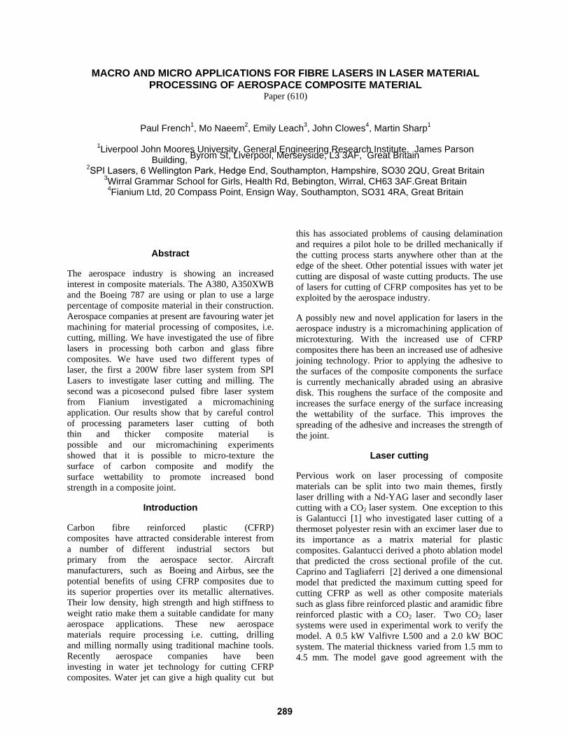
The SPI Lasers fibre laser has a maximum power of 200W and was delivered to the samples via a 10µm core optical fibre. The process cutting head shown in figure 1 had a 76 mm processing lens with a 76 mm recollimating lens. For these particular cutting experiments 50W and 100W were the mean powers used in the experimental investigation. The focused spot diameter was 20 - 25 µm and the focus was on the surface of the sample. The nozzle stand off was 100 µm with a nozzle exit diameter of 0.8 mm. The laser was operated in a continuous wave mode.
Figure 1: Experimental set-up of the SPI Fiber Laser showing the cutting head
2.2 Surface Texturing Experimental Set-up
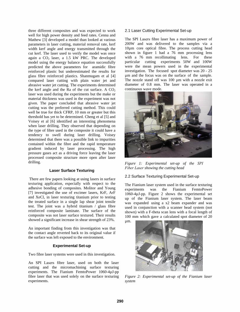
The Fianium laser system used in the surface texturing experiments was the Fianium FemtoPower 1060-4µJ-pp. Figure 2 shows the experimental set up of the Fianium laser system. The laser beam was expanded using a x2 beam expander and was used in conjunction with a scanner head system (not shown) with a F-theta scan lens with a focal length of 100 mm which gave a calculated spot diameter of 20 µm.
Figure 2: Experimental set-up of the Fianium laser system
290
The SPI Laser was also used in the surface texturing experiments using their scanning head with a 100 mm focal length theta lens which gave a spot diameter of 25 µm.
2.3 Aerospace Material
The composite material used in this study was a pre-impregnated (“pre-preg”) material, a stitched carbon toughened epoxy resin 5 harness satin weave MTM44-1. The sample thickness was 330 µm. The second material investigated was E-glass fibre reinforced epoxy resin composite (GFRP). The thickness of the GFRP was 2.3 mm thick.
Experimental Results
3.1 Laser Cutting of CFRP
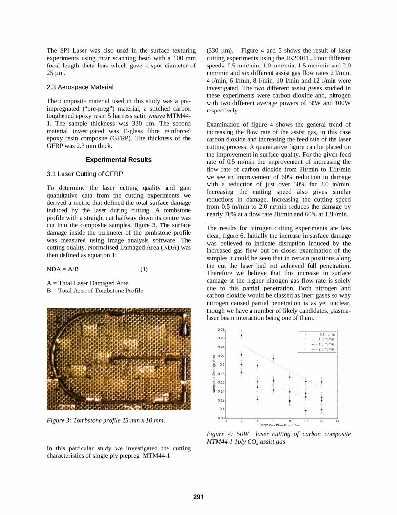
To determine the laser cutting quality and gain quantitative data from the cutting experiments we derived a metric that defined the total surface damage induced by the laser during cutting. A tombstone profile with a straight cut halfway down its centre was cut into the composite samples, figure 3. The surface damage inside the perimeter of the tombstone profile was measured using image analysis software. The cutting quality, Normalised Damaged Area (NDA) was then defined as equation 1:
NDA = A/B (1)
A = Total Laser Damaged Area B = Total Area of Tombstone Profile
Figure 3: Tombstone profile 15 mm x 10 mm.
In this particular study we investigated the cutting characteristics of single ply prepreg MTM44-1
(330 µm). Figure 4 and 5 shows the result of laser cutting experiments using the JK200FL. Four different speeds, 0.5 mm/min, 1.0 mm/min, 1.5 mm/min and 2.0 mm/min and six different assist gas flow rates 2 l/min, 4 l/min, 6 l/min, 8 l/min, 10 l/min and 12 l/min were investigated. The two different assist gases studied in these experiments were carbon dioxide and, nitrogen with two different average powers of 50W and 100W respectively.
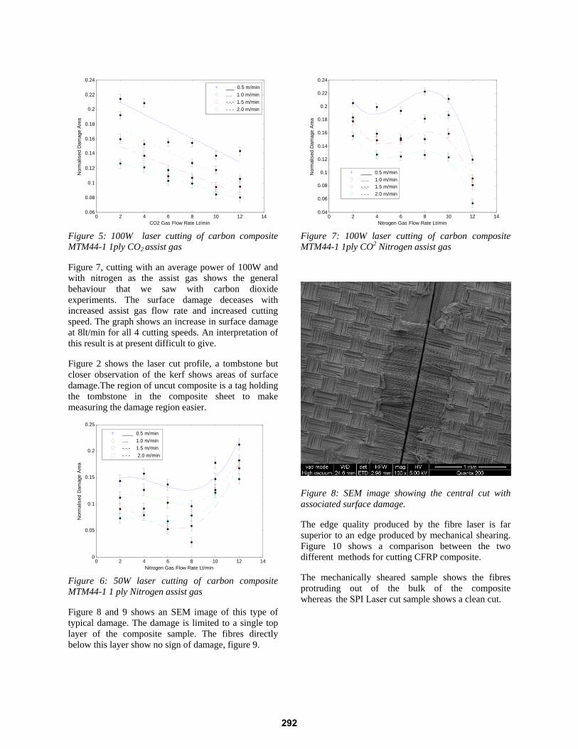
Examination of figure 4 shows the general trend of increasing the flow rate of the assist gas, in this case carbon dioxide and increasing the feed rate of the laser cutting process. A quantitative figure can be placed on the improvement in surface quality. For the given feed rate of 0.5 m/min the improvement of increasing the flow rate of carbon dioxide from 2lt/min to 12lt/min we see an improvement of 60% reduction in damage with a reduction of just over 50% for 2.0 m/min. Increasing the cutting speed also gives similar reductions in damage. Increasing the cutting speed from 0.5 m/min to 2.0 m/min reduces the damage by nearly 70% at a flow rate 2lt/min and 60% at 12lt/min.
The results for nitrogen cutting experiments are less clear, figure 6. Initially the increase in surface damage was believed to indicate disruption induced by the increased gas flow but on closer examination of the samples it could be seen that in certain positions along the cut the laser had not achieved full penetration. Therefore we believe that this increase in surface damage at the higher nitrogen gas flow rate is solely due to this partial penetration. Both nitrogen and carbon dioxide would be classed as inert gases so why nitrogen caused partial penetration is as yet unclear, though we have a number of likely candidates, plasma-laser beam interaction being one of them.
0 2 4 6 8 10 12 140.08
0.1
0.12
0.14
0.16
0.18
0.2
0.22
0.24
0.26
0.28
CO2 Gas Flow Rate Lt/min
Nor
mal
ised
Dam
age
Are
a
____ 0.5 m/min..... 1.0 m/min-.-.- 1.5 m/min- - - 2.0 m/min
Figure 4: 50W laser cutting of carbon composite MTM44-1 1ply CO2 assist gas
291
0 2 4 6 8 10 12 140.06
0.08
0.1
0.12
0.14
0.16
0.18
0.2
0.22
0.24
CO2 Gas Flow Rate Lt/min
Nor
mal
ised
Dam
age
Are
a
___ 0.5 m/min.... 1.0 m/min-.-.- 1.5 m/min- - - 2.0 m/min
Figure 5: 100W laser cutting of carbon composite MTM44-1 1ply CO2 assist gas
Figure 7, cutting with an average power of 100W and with nitrogen as the assist gas shows the general behaviour that we saw with carbon dioxide experiments. The surface damage deceases with increased assist gas flow rate and increased cutting speed. The graph shows an increase in surface damage at 8lt/min for all 4 cutting speeds. An interpretation of this result is at present difficult to give.
Figure 2 shows the laser cut profile, a tombstone but closer observation of the kerf shows areas of surface damage.The region of uncut composite is a tag holding the tombstone in the composite sheet to make measuring the damage region easier.
0 2 4 6 8 10 12 140
0.05
0.1
0.15
0.2
0.25
Nitrogen Gas Flow Rate Lt/min
Nor
mal
ised
Dam
age
Are
a
____ 0.5 m/min.... 1.0 m/min-.-.- 1.5 m/min- - - 2.0 m/min
Figure 6: 50W laser cutting of carbon composite MTM44-1 1 ply Nitrogen assist gas
Figure 8 and 9 shows an SEM image of this type of typical damage. The damage is limited to a single top layer of the composite sample. The fibres directly below this layer show no sign of damage, figure 9.
0 2 4 6 8 10 12 140.04
0.06
0.08
0.1
0.12
0.14
0.16
0.18
0.2
0.22
0.24
Nitrogen Gas Flow Rate Lt/min
Nor
mal
ised
Dam
age
Are
a
____ 0.5 m/min..... 1.0 m/min-.-.- 1.5 m/min- - - 2.0 m/min
Figure 7: 100W laser cutting of carbon composite MTM44-1 1ply CO2 Nitrogen assist gas
Figure 8: SEM image showing the central cut with associated surface damage.
The edge quality produced by the fibre laser is far superior to an edge produced by mechanical shearing. Figure 10 shows a comparison between the two different methods for cutting CFRP composite.
The mechanically sheared sample shows the fibres protruding out of the bulk of the composite whereas the SPI Laser cut sample shows a clean cut.
292
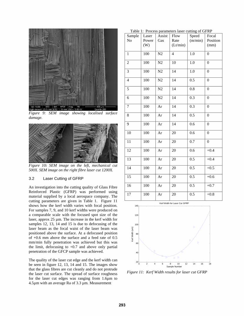
Figure 9: SEM image showing localised surface damage.
Figure 10: SEM image on the left, mechanical cut 500X. SEM image on the right fibre laser cut 1200X.
3.2 Laser Cutting of GFRP
An investigation into the cutting quality of Glass Fibre Reinforced Plastic (GFRP) was performed using material supplied by a local aerospace company. The cutting parameters are given in Table 1. Figure 11 shows how the kerf width varies with focal position. For samples 7, 9, and 10 kerf widths were produced on a comparable scale with the focused spot size of the laser, approx 25 µm. The increase in the kerf width for samples 12, 13, 14 and 15 is due to defocusing of the laser beam as the focal waist of the laser beam was positioned above the surface. At a defocused position of +0.6 mm above the surface and a feed rate of 0.5 mm/min fully penetration was achieved but this was the limit, defocusing to +0.7 and above only partial penetration of the GFCP sample was achieved.
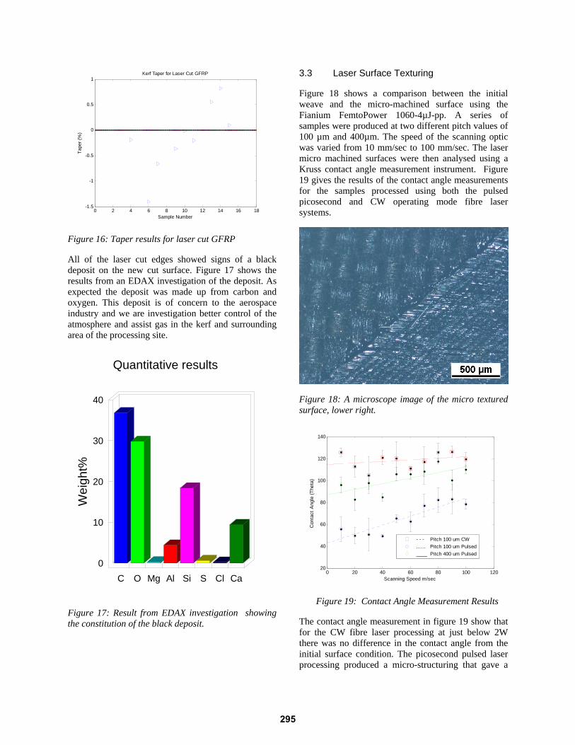
The quality of the laser cut edge and the kerf width can be seen in figure 12, 13, 14 and 15. The images show that the glass fibres are cut cleanly and do not protrude the laser cut surface. The spread of surface roughness for the laser cut edges was ranging from 1.6µm to 4.5µm with an average Ra of 3.3 µm. Measurement
Table 1: Process parameters laser cutting of GFRP Sample No
Laser Power (W)
Assist Gas
Flow Rate (Lt/min)
Speed (m/min)
Focal Position (mm)
1 100 N2 4 1.0 0
2 100 N2 10 1.0 0
3 100 N2 14 1.0 0
4 100 N2 14 0.5 0
5 100 N2 14 0.8 0
6 100 N2 14 0.3 0
7 100 Ar 14 0.3 0
8 100 Ar 14 0.5 0
9 100 Ar 14 0.6 0
10 100 Ar 20 0.6 0
11 100 Ar 20 0.7 0
12 100 Ar 20 0.6 +0.4
13 100 Ar 20 0.5 +0.4
14 100 Ar 20 0.5 +0.5
15 100 Ar 20 0.5 +0.6
16 100 Ar 20 0.5 +0.7
17 100 Ar 20 0.5 +0.8
0 2 4 6 8 10 12 14 16 1820
40
60
80
100
120
140Kerf Width for Laser Cut GFRP
Sample Number
Ker
f Wid
th (u
m)
Figure 11: Kerf Width results for laser cut GFRP
293
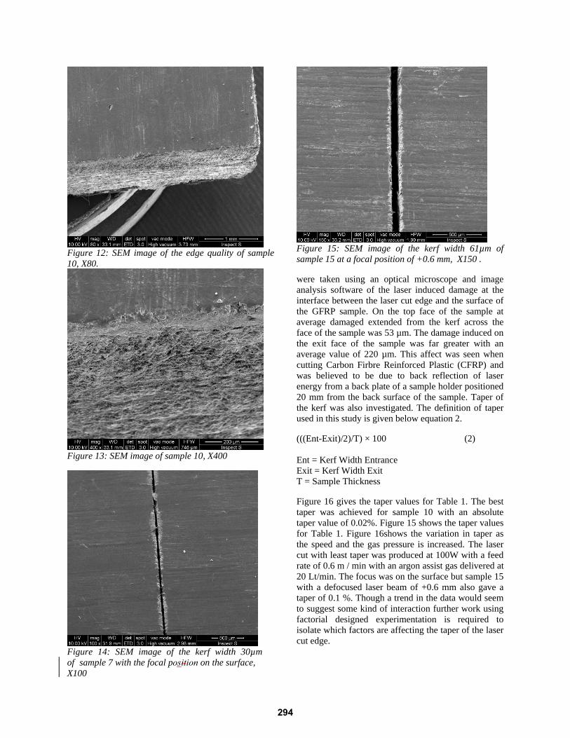
Figure 12: SEM image of the edge quality of sample 10, X80.
Figure 13: SEM image of sample 10, X400
Figure 14: SEM image of the kerf width 30µm of sample 7 with the focal position on the surface, X100
Figure 15: SEM image of the kerf width 61µm of sample 15 at a focal position of +0.6 mm, X150 .
were taken using an optical microscope and image analysis software of the laser induced damage at the interface between the laser cut edge and the surface of the GFRP sample. On the top face of the sample at average damaged extended from the kerf across the face of the sample was 53 µm. The damage induced on the exit face of the sample was far greater with an average value of 220 µm. This affect was seen when cutting Carbon Firbre Reinforced Plastic (CFRP) and was believed to be due to back reflection of laser energy from a back plate of a sample holder positioned 20 mm from the back surface of the sample. Taper of the kerf was also investigated. The definition of taper used in this study is given below equation 2.
(((Ent-Exit)/2)/T) × 100 (2)
Ent = Kerf Width Entrance Exit = Kerf Width Exit T = Sample Thickness
Figure 16 gives the taper values for Table 1. The best taper was achieved for sample 10 with an absolute taper value of 0.02%. Figure 15 shows the taper values for Table 1. Figure 16shows the variation in taper as the speed and the gas pressure is increased. The laser cut with least taper was produced at 100W with a feed rate of 0.6 m / min with an argon assist gas delivered at 20 Lt/min. The focus was on the surface but sample 15 with a defocused laser beam of +0.6 mm also gave a taper of 0.1 %. Though a trend in the data would seem to suggest some kind of interaction further work using factorial designed experimentation is required to isolate which factors are affecting the taper of the laser cut edge.
294
0 2 4 6 8 10 12 14 16 18-1.5
-1
-0.5
0
0.5
1Kerf Taper for Laser Cut GFRP
Sample Number
Tape
r (%
)
Figure 16: Taper results for laser cut GFRP
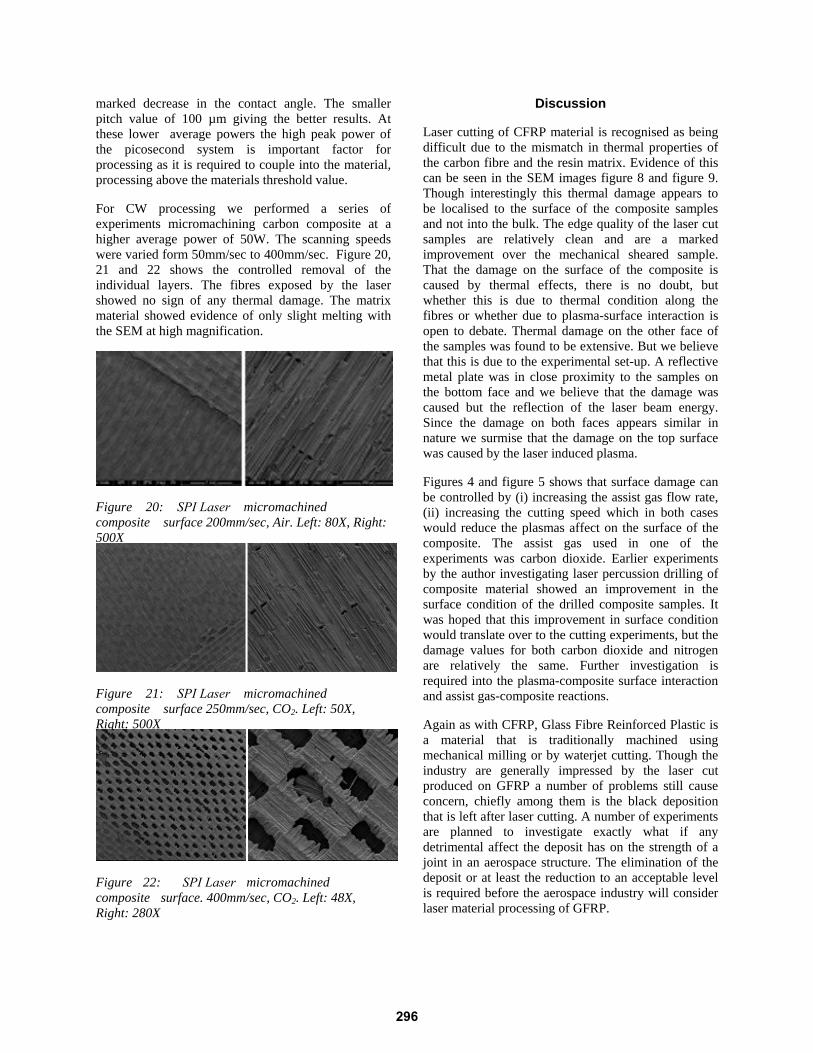
All of the laser cut edges showed signs of a black deposit on the new cut surface. Figure 17 shows the results from an EDAX investigation of the deposit. As expected the deposit was made up from carbon and oxygen. This deposit is of concern to the aerospace industry and we are investigation better control of the atmosphere and assist gas in the kerf and surrounding area of the processing site.
Quantitative results
Wei
ght%
0
10
20
30
40
C O Mg Al Si S Cl Ca
Figure 17: Result from EDAX investigation showing the constitution of the black deposit.
3.3 Laser Surface Texturing
Figure 18 shows a comparison between the initial weave and the micro-machined surface using the Fianium FemtoPower 1060-4µJ-pp. A series of samples were produced at two different pitch values of 100 µm and 400µm. The speed of the scanning optic was varied from 10 mm/sec to 100 mm/sec. The laser micro machined surfaces were then analysed using a Kruss contact angle measurement instrument. Figure 19 gives the results of the contact angle measurements for the samples processed using both the pulsed picosecond and CW operating mode fibre laser systems.
Figure 18: A microscope image of the micro textured surface, lower right.
0 20 40 60 80 100 12020
40
60
80
100
120
140
Scanning Speed m/sec
Con
tact
Ang
le (T
heta
)
- - - Pitch 100 um CW...... Pitch 100 um Pulsed____ Pitch 400 um Pulsed
Figure 19: Contact Angle Measurement Results
The contact angle measurement in figure 19 show that for the CW fibre laser processing at just below 2W there was no difference in the contact angle from the initial surface condition. The picosecond pulsed laser processing produced a micro-structuring that gave a
295
marked decrease in the contact angle. The smaller pitch value of 100 µm giving the better results. At these lower average powers the high peak power of the picosecond system is important factor for processing as it is required to couple into the material, processing above the materials threshold value.
For CW processing we performed a series of experiments micromachining carbon composite at a higher average power of 50W. The scanning speeds were varied form 50mm/sec to 400mm/sec. Figure 20, 21 and 22 shows the controlled removal of the individual layers. The fibres exposed by the laser showed no sign of any thermal damage. The matrix material showed evidence of only slight melting with the SEM at high magnification.
Figure 20: SPI Laser micromachined composite surface 200mm/sec, Air. Left: 80X, Right: 500X
Figure 21: SPI Laser micromachined composite surface 250mm/sec, CO2. Left: 50X, Right: 500X
Figure 22: SPI Laser micromachined composite surface. 400mm/sec, CO2. Left: 48X, Right: 280X
Discussion
Laser cutting of CFRP material is recognised as being difficult due to the mismatch in thermal properties of the carbon fibre and the resin matrix. Evidence of this can be seen in the SEM images figure 8 and figure 9. Though interestingly this thermal damage appears to be localised to the surface of the composite samples and not into the bulk. The edge quality of the laser cut samples are relatively clean and are a marked improvement over the mechanical sheared sample. That the damage on the surface of the composite is caused by thermal effects, there is no doubt, but whether this is due to thermal condition along the fibres or whether due to plasma-surface interaction is open to debate. Thermal damage on the other face of the samples was found to be extensive. But we believe that this is due to the experimental set-up. A reflective metal plate was in close proximity to the samples on the bottom face and we believe that the damage was caused but the reflection of the laser beam energy. Since the damage on both faces appears similar in nature we surmise that the damage on the top surface was caused by the laser induced plasma.
Figures 4 and figure 5 shows that surface damage can be controlled by (i) increasing the assist gas flow rate, (ii) increasing the cutting speed which in both caseswould reduce the plasmas affect on the surface of thecomposite. The assist gas used in one of theexperiments was carbon dioxide. Earlier experimentsby the author investigating laser percussion drilling ofcomposite material showed an improvement in thesurface condition of the drilled composite samples. Itwas hoped that this improvement in surface conditionwould translate over to the cutting experiments, but thedamage values for both carbon dioxide and nitrogenare relatively the same. Further investigation isrequired into the plasma-composite surface interactionand assist gas-composite reactions.
Again as with CFRP, Glass Fibre Reinforced Plastic is a material that is traditionally machined using mechanical milling or by waterjet cutting. Though the industry are generally impressed by the laser cut produced on GFRP a number of problems still cause concern, chiefly among them is the black deposition that is left after laser cutting. A number of experiments are planned to investigate exactly what if any detrimental affect the deposit has on the strength of a joint in an aerospace structure. The elimination of the deposit or at least the reduction to an acceptable level is required before the aerospace industry will consider laser material processing of GFRP.
296
The SEM images show that a laser cut produces relative straight edges with minimal surface damage on the substrate. The excessive damage produced on the exit side of the GFRP samples we believe is solely due to bak reflection of the laser beam from the back plate of the sample holder. This was a problem observed during our laser cutting experiments with the CFRP. Steps have been taken to cure this problem.
The quality of the laser cut edge with respect to such factors as fibre protrusion and surface roughness the results for the investigation are very promising. Unlike with the CFRP cutting trials, the GFRP cut edges showed no sign of striations. This may be due to the relatively low gas flows used in these experiments and inivdence of the striation may be hidden by glass remelt on the cut surface.
Laser surface texturing of composites material for the aerospace industry is gaining a great deal of interest. Figure 18 shows that using a laser to micro-machine a composite surface is a viable laser process for increasing the surface energy and promoting a strong adhesive joint. The Fianium laser system operating at a relatively low average power, approximately 2W produced a fine groove structure that more than halved the contact angle for the composite surface. The JK200FL working in the region of 2W and in CW mode, with all things equal did not produce any structuring, but at 50W and higher scan speeds 100mm/sec – 400 mm/sec produced fine structures and showed the laser capable of machining flat areas on a macro scale 20 mm x 20 mm. This could open the possibility for both fibre laser systems of using in a new and novel application of laser milling of aerospace composite material.
Conclusion
This investigation has shown that it is possible to use the new generation of fibre lasers in both a macro-application of laser cutting and a micro-application of laser surface texturing for adhesive bonding of aerospace structures. The cut edge quality compared to mechanical cutting is superior though surface damage may remain an issue. Work is in progress to reduce this damage further and increase the cutting speed.
Surface texturing of composites is a viable replacement to mechanical abrading giving better control over the final structured surface. The contact angle of the composite material showed a marked reduction. The fibre laser systems have shown that they can machine CFRP with a fine control over the depth of material removed and a high quality surface finish. This ability to machine on the micro scale could give fibre lasers a new role in the aerospace industry as
a new tool for laser milling of fine structures in CFRP. Further work into this application is required.
Reference
[1] Galantucci.L.M. Excimer Laser Cutting:Experimental Characterisation and 3DNumerical Modelling for Polyester Resins.Annals of the CIRP Vol. 47/1/1998. Pages 141– 144.
[2] Caprino C, Tagliaferri V. Maximum CutingSpeed in Laser Cutting of Fibre ReinforcedPlastics. Int. J. Mach. Tools Manufact. Vol. 28.No 4. (1988). Pages 389 – 398.
[3] Cenna A. A, Mathew P. Analysis and predictionof laser cutting parameters of fibre reinforcedplastic (FRP) composite materials. Int. J. Mach.Tools Manufact.. 42. (2002). Pages 105 – 113.
[4] Shanmugam D.K, Chen F.L, Siores E, BrandtM. Compartive study of jetting machiningtechnologies over laser machining technologyfor cutting composite material. CompositeStructures 57. (2002). Pages 289 – 296.
[5] Cheng C.F, Tsui Y.C, Clyne T.W. Applicationof a 3-D heat flow model to treat laser drillingof carbon fibre composites. Acta MetallMater(1998). 46 Pages 4273 – 4285.
[6] Voisey K.T, Fouquet S, Roy D, Clyne T.W.Fibre swelling during laser drilling of carbonfibre composites. Optics and Lasers inEngineering. 44 (2006). Pages 1185 – 1197.
[7] Molitor P, Young T. Investigation into the useof excimer laser irradiation as a titanium alloysurface treatment in a metal to compositeadhesive bond. International Journal ofAdhesion & Adhesives. 24. (2004). Pages 127 –134.
Acknowledgments
The Photonics in Engineering Group, based in the General Engineering Research Institute at the Liverpool John Moores University, wish to thank our colleagues at SPI Lasers for their support on this project. We wish to thank Emily Leach our Nuffield Placement student for all her help with this project. We also wish to thank our former colleagues at Lairdside Laser Engineering Centre for their help.
297