machine automation controller nj/nx-series ethercat
TRANSCRIPT

Machine Automation ControllerNJ/NX-series
EtherCAT® TroubleshootingPractices Guide
P114-E1-01

-
• Sysmac and SYSMAC are trademarks or registered trademarks of OMRON Corporation in Japan and other countries for OMRON factory automation products.
• Microsoft, Windows, Windows Vista, Excel, and Visual Basic are either registered trademarks or trademarks of Microsoft Corporation in the United States and other countries.
• EtherCAT® is registered trademark and patented technology, licensed by Beckhoff Automation GmbH, Germany.
Other company names and product names in this document are the trademarks or registered trademarks of their respective companies.
Trademarks
All rights reserved. No part of this publication may be reproduced, stored in a retrieval system, or transmitted, inany form, or by any means, mechanical, electronic, photocopying, recording, or otherwise, without the priorwritten permission of OMRON.No patent liability is assumed with respect to the use of the information contained herein. Moreover, becauseOMRON is constantly striving to improve its high-quality products, the information contained in this guide issubject to change without notice. Every precaution has been taken in the preparation of this guide. Nevertheless, OMRON assumes no responsibility for errors or omissions. Neither is any liability assumed for damagesresulting from the use of the information contained in this publication.
NOTE

Introduction
Introduction
Thank you for purchasing an NJ/NX-series CPU Unit.
This guide describes the troubleshooting procedures for using the built-in EtherCAT port on an NJ/NX-series CPU Unit.
Please read this guide and make sure you understand the functions that are required for troubleshoot-ing before you attempt to use the product in a control system and when building and maintaining a sys-tem.
Keep this guide in a safe place where it will be available for reference during operation.
This manual is intended for the following personnel, who must also have knowledge of electrical sys-tems (an electrical engineer or the equivalent).
• Personnel in charge of introducing FA systems.
• Personnel in charge of designing FA systems.
• Personnel in charge of installing and maintaining FA systems.
• Personnel in charge of managing FA systems and facilities.
For programming, this guide is intended for personnel who understand the programming language specifications in international standard IEC 61131-3 or Japanese standard JIS B 3503.
This guide covers the following products.
• NX-series CPU Units
• NX701-17
• NX701-16
• NJ-series CPU Units
• NJ501-15
• NJ501-14
• NJ501-13
• NJ301-12
• NJ301-11
• NJ101-10
• NJ101-90
Part of the specifications and restrictions for the CPU Units are given in other manuals. Refer to Related Manuals on page 7.
Intended Audience
Applicable Products
1NJ/NX-series EtherCAT Troubleshooting Practices Guide (P114)

Guide Structure
Guide Structure
The following page structure and icons are used in this guide
Note This illustration is provided only as a sample. It may not literally appear in this manual.
Page Structure and Icons
4-9
4 Installation and Wiring
NJ-series CPU Unit Hardware User’s Manual (W500)
sti
nU
gni
tn
uo
M 3-
4
4
stne
nop
moC
rell
ortn
oC
gnit
cenn
oC
1-3-
4
4-3 Mounting Units
The Units that make up an NJ-series Controller can be connected simply by pressing the Units togetherand locking the sliders by moving them toward the back of the Units. The End Cover is connected in thesame way to the Unit on the far right side of the Controller.
1 Join the Units so that the connectors fit exactly.
2 The yellow sliders at the top and bottom of each Unit lock the Units together. Move the sliders
toward the back of the Units as shown below until they click into place.
Precautions for Correct UsePrecautions for Correct Use
4-3-1 Connecting Controller Components
ConnectorHook Hook holes
Slider
Lock
Release
Move the sliders toward the back until they lock into place.
Level 1 headingLevel 2 headingLevel 3 headingLevel 2 heading
A step in a procedure
Manual name
Special information
Level 3 heading
Page tab
Gives the current headings.
Indicates a procedure.
Icons indicate precautions, additional information, or reference information.
Gives the number of the main section.
The sliders on the tops and bottoms of the Power Supply Unit, CPU Unit, I/O Units, Special I/O Units, and CPU Bus Units must be completely locked (until they click into place) after connecting the adjacent Unit connectors.
2 NJ/NX-series EtherCAT Troubleshooting Practices Guide (P114)

Guide Structure
Special information in this guide is classified as follows:
Note References are provided to more detailed or related information.
Special Information
Precautions for Safe UsePrecautions on what to do and what not to do to ensure safe usage of the product.
Precautions for Correct UsePrecautions on what to do and what not to do to ensure proper operation and performance.
Additional InformationAdditional information to read as required.This information is provided to increase understanding or make operation easier.
Version InformationInformation on differences in specifications and functionality for CPU Units and EtherCAT Coupler Units with different unit versions and for different versions of the Sysmac Studio is given.
3NJ/NX-series EtherCAT Troubleshooting Practices Guide (P114)

Terms and Conditions Agreement
Terms and Conditions Agreement
Exclusive Warranty
Omron’s exclusive warranty is that the Products will be free from defects in materials and workman-ship for a period of twelve months from the date of sale by Omron (or such other period expressed in writing by Omron). Omron disclaims all other warranties, express or implied.
Limitations
OMRON MAKES NO WARRANTY OR REPRESENTATION, EXPRESS OR IMPLIED, ABOUT NON-INFRINGEMENT, MERCHANTABILITY OR FITNESS FOR A PARTICULAR PURPOSE OF THE PRODUCTS. BUYER ACKNOWLEDGES THAT IT ALONE HAS DETERMINED THAT THE PRODUCTS WILL SUITABLY MEET THE REQUIREMENTS OF THEIR INTENDED USE.
Omron further disclaims all warranties and responsibility of any type for claims or expenses based on infringement by the Products or otherwise of any intellectual property right.
Buyer Remedy
Omron’s sole obligation hereunder shall be, at Omron’s election, to (i) replace (in the form originally shipped with Buyer responsible for labor charges for removal or replacement thereof) the non-com-plying Product, (ii) repair the non-complying Product, or (iii) repay or credit Buyer an amount equal to the purchase price of the non-complying Product; provided that in no event shall Omron be responsible for warranty, repair, indemnity or any other claims or expenses regarding the Products unless Omron’s analysis confirms that the Products were properly handled, stored, installed and maintained and not subject to contamination, abuse, misuse or inappropriate modification. Return of any Products by Buyer must be approved in writing by Omron before shipment. Omron Companies shall not be liable for the suitability or unsuitability or the results from the use of Products in combi-nation with any electrical or electronic components, circuits, system assemblies or any other materi-als or substances or environments. Any advice, recommendations or information given orally or in writing, are not to be construed as an amendment or addition to the above warranty.
See http://www.omron.com/global/ or contact your Omron representative for published information.
OMRON COMPANIES SHALL NOT BE LIABLE FOR SPECIAL, INDIRECT, INCIDENTAL, OR CON-SEQUENTIAL DAMAGES, LOSS OF PROFITS OR PRODUCTION OR COMMERCIAL LOSS IN ANY WAY CONNECTED WITH THE PRODUCTS, WHETHER SUCH CLAIM IS BASED IN CONTRACT, WARRANTY, NEGLIGENCE OR STRICT LIABILITY.
Further, in no event shall liability of Omron Companies exceed the individual price of the Product on which liability is asserted.
Warranty, Limitations of Liability
Warranties
Limitation on Liability; Etc
4 NJ/NX-series EtherCAT Troubleshooting Practices Guide (P114)
Terms and Conditions Agreement
Omron Companies shall not be responsible for conformity with any standards, codes or regulations which apply to the combination of the Product in the Buyer’s application or use of the Product. At Buyer’s request, Omron will provide applicable third party certification documents identifying ratings and limitations of use which apply to the Product. This information by itself is not sufficient for a com-plete determination of the suitability of the Product in combination with the end product, machine, sys-tem, or other application or use. Buyer shall be solely responsible for determining appropriateness of the particular Product with respect to Buyer’s application, product or system. Buyer shall take applica-tion responsibility in all cases.
NEVER USE THE PRODUCT FOR AN APPLICATION INVOLVING SERIOUS RISK TO LIFE OR PROPERTY WITHOUT ENSURING THAT THE SYSTEM AS A WHOLE HAS BEEN DESIGNED TO ADDRESS THE RISKS, AND THAT THE OMRON PRODUCT(S) IS PROPERLY RATED AND INSTALLED FOR THE INTENDED USE WITHIN THE OVERALL EQUIPMENT OR SYSTEM.
Omron Companies shall not be responsible for the user’s programming of a programmable Product, or any consequence thereof.
Data presented in Omron Company websites, catalogs and other materials is provided as a guide for the user in determining suitability and does not constitute a warranty. It may represent the result of Omron’s test conditions, and the user must correlate it to actual application requirements. Actual perfor-mance is subject to the Omron’s Warranty and Limitations of Liability.
Product specifications and accessories may be changed at any time based on improvements and other reasons. It is our practice to change part numbers when published ratings or features are changed, or when significant construction changes are made. However, some specifications of the Product may be changed without any notice. When in doubt, special part numbers may be assigned to fix or establish key specifications for your application. Please consult with your Omron’s representative at any time to confirm actual specifications of purchased Product.
Information presented by Omron Companies has been checked and is believed to be accurate; how-ever, no responsibility is assumed for clerical, typographical or proofreading errors or omissions.
Application Considerations
Suitability of Use
Programmable Products
Disclaimers
Performance Data
Change in Specifications
Errors and Omissions
5NJ/NX-series EtherCAT Troubleshooting Practices Guide (P114)

Safety Precautions
Safety Precautions
(a) Understand the specifications of devices which are used in the system. Allow some margin for rat-ings and performance. Provide safety measures, such as installing a safety circuit, in order to ensure safety and minimize the risk of abnormal occurrence.
(b) To ensure system safety, make sure to always read and follow the information provided in all Safety Precautions, Precautions for Safe Use, and Precautions for Correct Use in the manuals for each device which is used in the system.
(c) The user is encouraged to confirm the standards and regulations that the system must conform to.
(d) It is prohibited to copy, to reproduce, and to distribute a part or the whole of this document without the permission of OMRON Corporation.
For safety precautions related to the NJ/NX-series CPU Unit, refer to the following manuals.
• NX-series CPU Unit Hardware User’s Manual (Cat. No. W535)
• NJ-series CPU Unit Hardware User’s Manual (Cat. No. W500)
• NJ/NX-series CPU Unit Software User’s Manual (Cat. No. W501)
6 NJ/NX-series EtherCAT Troubleshooting Practices Guide (P114)

Related Manuals
Related Manuals
To ensure safe use of the system, be sure to obtain the manuals or other instructions for the devices and equipment that compose the system, and read and understand the contents of the manuals, in par-ticular warnings, cautions and other safety information, before using the system.
The followings are the manuals related to this manual. Use these manuals for reference.
Manual name Cat. No. Model numbers Application Description
NJ/NX-series EtherCAT Troubleshooting Prac-tices Guide
(this manual)
P114 NX701-NJ501-NJ301-NJ101-
Learning how to trouble-shoot the built-in Ether-CAT port on the NJ/NX-series CPU Unit.
Describes the EtherCAT troubleshooting proce-dures.
NX-series CPU Unit Hardware User’s Manual
W535 NX701- Learning the basic specifi-cations of the NX-series CPU Units, including intro-ductory information, designing, installation, and maintenance. Mainly hard-ware information is pro-vided.
An introduction to the entire NX-series system is provided along with the following information on the CPU Unit.
• Features and system configuration
• Introduction
• Part names and functions
• General specifications
• Installation and wiring
• Maintenance and inspection
Use this manual together with the NJ/NX-series CPU Unit Software User’s Manual (Cat. No. W501).
NJ-series CPU Unit Hardware User’s Manual
W500 NJ501-NJ301-NJ101-
Learning the basic specifi-cations of the NJ-series CPU Units, including intro-ductory information, designing, installation, and maintenance. Mainly hard-ware information is pro-vided.
An introduction to the entire NJ-series system is provided along with the following information on the CPU Unit.
• Features and system configuration
• Introduction
• Part names and functions
• General specifications
• Installation and wiring
• Maintenance and inspection
Use this manual together with the NJ/NX-series CPU Unit Software User’s Manual (Cat. No. W501).
NJ/NX-series CPU Unit Software User’s Manual
W501 NX701-NJ501-NJ301-NJ101-
Learning how to program and set up an NJ/NX-series CPU Unit.Mainly software informa-tion is provided.
The following information is provided on a Con-troller built with an NJ/NX-series CPU Unit.
• CPU Unit operation
• CPU Unit features
• Initial settings
• Programming based on IEC 61131-3 lan-guage specifications
Use this manual together with the NX-series CPU Unit Hardware User's Manual (Cat. No. W535) or NJ-series CPU Unit Hardware User's Manual (Cat. No. W500).
NJ/NX-series Motion Control Instructions Ref-erence Manual
W508 NX701-NJ501-NJ301-NJ101-
Learning about the specifi-cations of the motion con-trol instructions that are provided by OMRON.
The motion control instructions are described. When programming, use this manual together with the NX-series CPU Unit Hardware User's Manual (Cat. No. W535) or NJ-series CPU Unit Hardware User’s Manual (Cat. No. W500), NJ/NX-series CPU Unit Software User’s Manual (Cat. No. W501) and NJ/NX-series CPU Unit Motion Control User’s Manual (Cat. No. W507).
7NJ/NX-series EtherCAT Troubleshooting Practices Guide (P114)

Related Manuals
NJ/NX-series CPU Unit Built-in EtherCAT Port User’s Manual
W505 NX701-NJ501-NJ301-NJ101-
Using the built-in EtherCAT port on an NJ/NX-series CPU Unit.
Information on the built-in EtherCAT port is pro-vided. This manual provides an introduction and provides information on the configuration, fea-tures, and setup.Use this manual together with the NX-series CPU Unit Hardware User's Manual (Cat. No. W535) or NJ-series CPU Unit Hardware User’s Manual (Cat. No. W500) and NJ/NX-series CPU Unit Software User’s Manual (Cat. No. W501).
NJ/NX-series Trouble-shooting Manual
W503 NX701-NJ501-NJ301-NJ101-
Learning about the errors that may be detected in an NJ/NX-series Controller.
Concepts on managing errors that may be detected in an NJ/NX-series Controller and information on individual errors are described.Use this manual together with the NX-series CPU Unit Hardware User's Manual (Cat. No. W535) or NJ-series CPU Unit Hardware User’s Manual (Cat. No. W500) and NJ/NX-series CPU Unit Software User’s Manual (Cat. No. W501).
Sysmac Studio Version 1 Operation Manual
W504 SYS-MAC-SE2
Learning about the operat-ing procedures and func-tions of the Sysmac Studio.
Describes the operating procedures of the Sys-mac Studio.
NX-seriesEtherCAT Coupler UnitUser’s Manual
W519 NX-ECC Learning how to use an NX-series EtherCAT Cou-pler Unit and EtherCAT Slave Terminals
The system and configuration of EtherCAT Slave Terminals, which consist of an NX-series EtherCAT Coupler Unit and NX Units, are described along with the hardware, setup, and functions of the EtherCAT Coupler Unit that are required to configure, control, and monitor NX Units through EtherCAT.
G5-series with Built-in EtherCAT Communica-tions User's Manual
I576 R88M-K
R88D-KN-ECT
Learning how to use the AC Servomotors/Servo Drives with built-in Ether-CAT Communications.
Describes the hardware, setup methods and functions of the AC Servomotors/Servo Drives with built-in EtherCAT Communications.
The linear motor type model and the model ded-icated for position controls are available in G5-series.
GX-series EtherCAT Slave Units User's Man-ual
W488 GX-ID
GX-OD
GX-OC
GX-MD
GX-AD
GX-DA
GX-EC
XWT-ID
XWT-OD
Learning how to use the EtherCAT remote I/O ter-minals.
Learning how to use the EtherCAT remote I/O terminals.
MX2/RX Series Ether-CAT Communication Unit User's Manual
I574 3G3AX-MX2-ECT
3G3AX-RX-ECT
Learning how to use Ether-CAT communication with an EtherCAT Communica-tions Unit installed on an MX-series or RX-series Inverter.
Explains how to install, wire, and configure set-tings on the EtherCAT Communications Unit, and describes common specifications of slaves, PDO, SDO, and other information.
FQ-M-series User's Man-ual
Z314 FQ-MS12 Learning the basic specifi-cations of FQ-M-series Vision Sensors.
Gives an overview of the FQ-M-series Sensor, and describes installation, settings, and adjust-ment.
EtherCAT Connection Guide Vision System (FH-series)
P577 NJ501-
NJ301-
FH-
Learning how to connect an FH-series Vision Sen-sor to an NJ-series system by EtherCAT.
Describes settings and procedures for connec-tion of the FH-series by EtherCAT.
ZW-series User's Manual Z332 ZW-CE1 Learning the basic specifi-cations of ZW-series Dis-placement Sensors.
Gives an overview of the ZW-series Sensor, and describes installation, settings, and adjustment.
Manual name Cat. No. Model numbers Application Description
8 NJ/NX-series EtherCAT Troubleshooting Practices Guide (P114)

Revision History
Revision History
A manual revision code appears as a suffix to the catalog number on the front and back covers of the manual.
Revision code Date Revised content
01 May 2016 Original production
P114-E1-01Revision code
Cat. No.
9NJ/NX-series EtherCAT Troubleshooting Practices Guide (P114)

CONTENTS
CONTENTS
Introduction ..............................................................................................................1Intended Audience....................................................................................................................................... 1Applicable Products ..................................................................................................................................... 1
Guide Structure ........................................................................................................2Page Structure and Icons ............................................................................................................................ 2Special Information ...................................................................................................................................... 3
Terms and Conditions Agreement ..........................................................................4Warranty, Limitations of Liability .................................................................................................................. 4Application Considerations .......................................................................................................................... 5Disclaimers .................................................................................................................................................. 5
Safety Precautions ...................................................................................................6
Related Manuals .......................................................................................................7
Revision History .......................................................................................................9
CONTENTS..............................................................................................................10
Section 1 What to do When an Error Occurs
1-1 General Flow of Troubleshooting ........................................................................................ 1-21-1-1 How to Identify an Error .............................................................................................................. 1-21-1-2 Resetting Errors .......................................................................................................................... 1-41-1-3 Flow of Troubleshooting.............................................................................................................. 1-5
1-2 Checking the Unit Status by the Indicators ........................................................................ 1-61-2-1 CPU Unit Operating Status ......................................................................................................... 1-61-2-2 EtherCAT Port Error Status ......................................................................................................... 1-81-2-3 Checking an Error that Occurs on a Slave.................................................................................. 1-9
1-3 Checking Event Information to Identify the Error ............................................................ 1-121-3-1 Event Logs with the Sysmac Studio.......................................................................................... 1-121-3-2 Checking the Error on the HMI (NA) (NJ/NX Troubleshooting Screen) .................................... 1-171-3-3 Checking the Error on the HMI (NS) (NS Troubleshooting Screen).......................................... 1-231-3-4 Checking the Error from a Program (Get Error Status Instruction) ........................................... 1-261-3-5 Detailed Information on Event Logs .......................................................................................... 1-28
1-4 Checking Errors Using the Communications Status ....................................................... 1-331-4-1 Getting Diagnostic/Statistical Information.................................................................................. 1-341-4-2 Checking for Errors Using Master Diagnostic and Statistical Information ................................. 1-351-4-3 Finding Locations of Errors Using the Slave Diagnostic and Statistical Information ................. 1-361-4-4 Identifying the Cause of the Error ............................................................................................. 1-371-4-5 Identifying Causes and Taking Corrective Action...................................................................... 1-401-4-6 Confirmation After Corrective Action......................................................................................... 1-411-4-7 Diagnostic and Statistical Information Display of Sysmac Studio.............................................. 1-421-4-8 Diagnostic and Statistical Log Function of the CPU Unit .......................................................... 1-49
1-5 Monitoring Specific Errors.................................................................................................. 1-531-5-1 Checking for Errors with System-defined Variables .................................................................. 1-53
1-6 Saving the Communications Status (For Inquiry to OMRON) ......................................... 1-55
1-7 Error (Event) List ................................................................................................................. 1-641-7-1 EtherCAT Master....................................................................................................................... 1-641-7-2 EtherCAT Slave......................................................................................................................... 1-64
10 NJ/NX-series EtherCAT Troubleshooting Practices Guide (P114)

CONTENTS
Section 2 Example Actions for Frequently Encountered Problems
2-1 Process Data Reception Timeout Error............................................................................... 2-22-1-1 Process Data Reception Timeout Error ...................................................................................... 2-22-1-2 General Flow of Troubleshooting................................................................................................ 2-32-1-3 Collecting Information for Troubleshooting ................................................................................. 2-32-1-4 Identifying the Cause.................................................................................................................. 2-42-1-5 Checking the Cause ................................................................................................................... 2-6
2-2 Slave Initialization Error........................................................................................................ 2-92-2-1 Slave Initialization Error .............................................................................................................. 2-92-2-2 General Flow of Troubleshooting.............................................................................................. 2-102-2-3 Check for a Major Fault Level Controller Error ..........................................................................2-112-2-4 Checking for Network Changes.................................................................................................2-112-2-5 Checking the Source of a Slave Initialization Error................................................................... 2-12
2-3 Troubleshooting for Identifying the Cause ....................................................................... 2-13
Section 3 Cautionary Information
11NJ/NX-series EtherCAT Troubleshooting Practices Guide (P114)

CONTENTS
12 NJ/NX-series EtherCAT Troubleshooting Practices Guide (P114)

1
This section describes the basic procedures for identifying and correcting errors that occur on an EtherCAT network.
1-1 General Flow of Troubleshooting . . . . . . . . . . . . . . . . . . . . . . . . . . . . . . . . . 1-21-1-1 How to Identify an Error . . . . . . . . . . . . . . . . . . . . . . . . . . . . . . . . . . . . . . . . . 1-2
1-1-2 Resetting Errors . . . . . . . . . . . . . . . . . . . . . . . . . . . . . . . . . . . . . . . . . . . . . . . 1-4
1-1-3 Flow of Troubleshooting . . . . . . . . . . . . . . . . . . . . . . . . . . . . . . . . . . . . . . . . . 1-5
1-2 Checking the Unit Status by the Indicators . . . . . . . . . . . . . . . . . . . . . . . . . 1-61-2-1 CPU Unit Operating Status . . . . . . . . . . . . . . . . . . . . . . . . . . . . . . . . . . . . . . . 1-6
1-2-2 EtherCAT Port Error Status . . . . . . . . . . . . . . . . . . . . . . . . . . . . . . . . . . . . . . . 1-8
1-2-3 Checking an Error that Occurs on a Slave . . . . . . . . . . . . . . . . . . . . . . . . . . . 1-9
1-3 Checking Event Information to Identify the Error . . . . . . . . . . . . . . . . . . . 1-121-3-1 Event Logs with the Sysmac Studio . . . . . . . . . . . . . . . . . . . . . . . . . . . . . . . 1-12
1-3-2 Checking the Error on the HMI (NA) (NJ/NX Troubleshooting Screen) . . . . 1-17
1-3-3 Checking the Error on the HMI (NS) (NS Troubleshooting Screen) . . . . . . . 1-23
1-3-4 Checking the Error from a Program (Get Error Status Instruction) . . . . . . . . 1-26
1-3-5 Detailed Information on Event Logs . . . . . . . . . . . . . . . . . . . . . . . . . . . . . . . 1-28
1-4 Checking Errors Using the Communications Status . . . . . . . . . . . . . . . . 1-331-4-1 Getting Diagnostic/Statistical Information . . . . . . . . . . . . . . . . . . . . . . . . . . . 1-34
1-4-2 Checking for Errors Using Master Diagnostic and Statistical Information . . 1-35
1-4-3 Finding Locations of Errors Using the Slave Diagnostic and Statistical Information . . . . . . . . . . . . . . . . . . . . . . . . . . . . . . . . . . . . . . . . . . 1-36
1-4-4 Identifying the Cause of the Error . . . . . . . . . . . . . . . . . . . . . . . . . . . . . . . . . 1-37
1-4-5 Identifying Causes and Taking Corrective Action . . . . . . . . . . . . . . . . . . . . . 1-40
1-4-6 Confirmation After Corrective Action . . . . . . . . . . . . . . . . . . . . . . . . . . . . . . 1-41
1-4-7 Diagnostic and Statistical Information Display of Sysmac Studio . . . . . . . . . 1-42
1-4-8 Diagnostic and Statistical Log Function of the CPU Unit . . . . . . . . . . . . . . . 1-49
1-5 Monitoring Specific Errors . . . . . . . . . . . . . . . . . . . . . . . . . . . . . . . . . . . . . 1-531-5-1 Checking for Errors with System-defined Variables . . . . . . . . . . . . . . . . . . . 1-53
1-6 Saving the Communications Status (For Inquiry to OMRON) . . . . . . . . . 1-55
1-7 Error (Event) List . . . . . . . . . . . . . . . . . . . . . . . . . . . . . . . . . . . . . . . . . . . . . 1-641-7-1 EtherCAT Master . . . . . . . . . . . . . . . . . . . . . . . . . . . . . . . . . . . . . . . . . . . . . 1-64
1-7-2 EtherCAT Slave . . . . . . . . . . . . . . . . . . . . . . . . . . . . . . . . . . . . . . . . . . . . . . 1-64
What to do When an Error Occurs
1 - 1NJ/NX-series EtherCAT Troubleshooting Practices Guide (P114)

1 What to do When an Error Occurs
1-1 General Flow of Troubleshooting
This section provides basic error identification and troubleshooting flowcharts. Use them when an error occurs in the NJ/NX-series Controller.
(1) Identification by indicators on front of CPU Unit
• CPU Unit operation status
The PWR indicator on the Power Supply Unit and the RUN and ERROR indicators on the CPU Unit indicate whether an error has occurred on the CPU Unit.
• EtherCAT port operation status
The EtherCAT NET ERR indicator of the EtherCAT port indicates whether an error has occurred that affects process data communication.
(2) Event log
This contains information about events that include errors.
You can check the event codes of current and past events, where each event occurred, what caused it, and the action to take in the Sysmac Studio or the HMI’s troubleshooting function.
You can acquire the event code of a current event using a Get Error Status instruction.
1-1-1 How to Identify an Error
Sysmac Studio
Event log
NJ/NX-series CPU Unit
EtherCAT
EtherCAT slave
Built-in EtherCAT port
(1) Indicators on front of CPU Unit
(4) Other methods for checking events
(2) Event log
You can check events recorded in the CPU Unit.
· System-defined variables· Get Error Status instruction· Packet monitoring function
You can check the status of the unit.
(3) Diagnostic and statistical information
You can diagnose the quality of communication conditions.
or
Event log
Error information
HMI
Error information
1 - 2 NJ/NX-series EtherCAT Troubleshooting Practices Guide (P114)

1 What to do When an Error Occurs1-1 G
eneral F
low
of Tro
ub
le-sh
oo
ting
1
1-1-1 H
ow to Ide
ntify an Error
(3) Diagnosis and statistical information
From the Sysmac Studio, you can check information used to diagnose the line quality of the EtherCAT network.
Use this function when you need to diagnose the line quality of the EtherCAT network, such as:
• Verifying whether the EtherCAT network was built correctly
• Investigating the cause of a communication error that occurred during normal operation
(4) Other methods for identifying errors
• System-defined variables
System-defined variables for EtherCAT communication. These variables are pre-defined in the global variable table.
You can read and write to system-defined variables from a user program to input the statuses of the EtherCAT master and slaves and set various parameters.
System-defined variables can be used from a user program, the monitor functions of the Sysmac Studio, and the data trace function of the Sysmac Studio.
The values of all system-defined variables related to an EtherCAT communication error do not change until the cause of the error is removed and the Controller error is reset using the troubleshoot functions of the Sysmac Studio or the ResetECError instruction.
• Get Error Status instruction
You can get an error status from a user program.
• Packet monitoring function
The packet monitoring function stores a certain number of the most recent packets sent and received by the EtherCAT master along with time information. Use this mainly when you need to inquire about a problem.
*1. The following steps are recommended for troubleshooting.
(1) Check indicators on front of CPU Unit.
(2) Event information
(3) Diagnostic and statistical information
(4) Other error checking methods
• System-defined variables
• Get Error Status instruction
• Packet monitoring function
1 - 3NJ/NX-series EtherCAT Troubleshooting Practices Guide (P114)

1 What to do When an Error Occurs
There are three methods to reset errors.
• Sysmac Studio
• HMI
• Execution of the Reset EtherCAT Error (ResetECError) instruction
For the reset methods, refer to the following.
• Sysmac Studio
Resetting Errors with the Sysmac Studio on page 1-15
• NA-series HMI
Event Logs on page 1-21
• NS-series HMI
Resetting Errors with an HMI on page 1-25
• EtherCAT error reset instruction (ResetECError)
NJ/NX-series Instructions Reference Manual (Cat. No. W502)
Even after the cause has been removed, an error on a slave will be retained until the error is reset, the power is turned OFF, and the slave is restarted.
After removing the cause, reset the error.
1 Identify and remove the cause of the error
Follow the troubleshooting procedure for each slave to identify and remove the error. For details, refer to the manuals for the slaves.
2 Reset the master/slave error
(1) Execute error reset on the EtherCAT Function Module to reset the slave error.
The following methods can be used to reset an error.
1) Instruction from the Sysmac Studio
2) Instruction from the HMI (troubleshooter)
3) Execute EtherCAT error reset instruction (ResetECError)
(2) If the error does not reset, it can be inferred that multiple causes exist. Repeat cause iden-tification, removal, and error reset until the error no longer occurs.
1-1-2 Resetting Errors
Resetting Slave Errors
1 - 4 NJ/NX-series EtherCAT Troubleshooting Practices Guide (P114)

1 What to do When an Error Occurs1-1 G
eneral F
low
of Tro
ub
le-sh
oo
ting
1
1-1-3 F
low of T
roubleshooting
1-1-3 Flow of Troubleshooting
Error occurs
No
Yes
Yes
No
If diagnosis of network line quality is necessary
Check event log
Refer to the NJ/NX-series Troubleshooting Manual
(Cat. No. W503)
Reset error
Check diagnostic and statistical information
End
Error related to EtherCAT?
Does error occur again?
Check error description. Refer to related manual and try correcting problem.
For the following errors, refer to section 2· Process Data Reception Timeout error
· Slave Initialization Error
1 - 5NJ/NX-series EtherCAT Troubleshooting Practices Guide (P114)

1 What to do When an Error Occurs
1-2 Checking the Unit Status by the Indi-cators
Statuses that can be checked by the indicators are indicated below.
*1 If you can connect communications to the CPU Unit from the Sysmac Studio with a direct connection via USB,
the CPU Unit is in PROGRAM mode. If you cannot connect communications, the CPU Unit is being reset.*3
*2 If you can connect communications to the CPU Unit from the Sysmac Studio with a direct connection via USB,
a major fault level error has occurred. If you cannot connect communications, a CPU Unit Error has occurred.*3
*3 If you cannot connect communications to the CPU Unit from the Sysmac Studio, it is also possible that the USB cable is faulty or that the connection type on the Sysmac Studio is not set for a direct connection via USB. Refer to the NJ/NX-series Troubleshooting Manual (Cat. No. W503) if you cannot connect communications to the CPU Unit.
1-2-1 CPU Unit Operating Status
NX-series CPU Unit
IndicatorsCPU Unit operating status
Error confirmation with the Sys-mac Studio or an HMIPWR RUN ERROR
Not lit Not lit Not lit Power Supply Error Not possible: Refer to the NJ/NX-series Troubleshooting Man-ual (Cat. No. W503).
Lit Not lit Not lit CPU Unit Reset*1
Lit Not lit or flashing
Lit CPU Unit Error*2
Lit Flashing for 30 s or longer
Not lit System Initialization Error
Lit Not lit Lit Major fault level*2 Possible: Connect the Sysmac Stu-dio or an HMI and check the cause of and correction for the error in the troubleshooting functions of the Sysmac Studio or the Trouble-shooter of the HMI.
Lit Lit Flashing Partial fault level
Lit Lit Flashing Minor fault level
Lit Lit Not lit Observation
Lit Lit Not lit Normal operation in RUN mode ---
Lit Not lit Not lit Normal operation in PROGRAM
mode*1 ---
Lit Flashing Not lit Normal operation in startup state ---
1 - 6 NJ/NX-series EtherCAT Troubleshooting Practices Guide (P114)

1 What to do When an Error Occurs1-2 C
heckin
g th
e Un
it Sta
tus b
y th
e Ind
icators
1
1-2-1 C
PU
Unit O
perating Status
*1 If you can connect communications to the CPU Unit from the Sysmac Studio with a direct connection via USB,
the CPU Unit is in PROGRAM mode. If you cannot connect communications, the CPU Unit is being reset.*3
*2 If you can connect communications to the CPU Unit from the Sysmac Studio with a direct connection via USB, a major fault level error has occurred. If you cannot connect communications, a watchdog timer error has
occurred in the CPU Unit.*3
*3 If you cannot connect communications to the CPU Unit from the Sysmac Studio, it is also possible that the USB cable is faulty or that the connection type on the Sysmac Studio is not set for a direct connection via USB. Refer to the NJ/NX-series Troubleshooting Manual (Cat. No. W503) if you cannot connect communications to the CPU Unit.
NJ-series CPU Unit
IndicatorsCPU Unit operating status
Error confirmation with the Sys-mac Studio or an HMIPWR RUN ERROR
Not lit Not lit Not lit Power Supply Error Not possible: Refer to the NJ/NX-series Troubleshooting Man-ual (Cat. No. W503).
Lit Not lit Not lit CPU Unit Reset*1
Lit Flashing Lit Incorrect Power Supply Unit Con-nected
Lit Not lit Lit CPU Unit Watchdog Timer Error*2
Lit Not lit Lit Major fault level*2 Possible: Connect the Sysmac Stu-dio or an HMI and check the cause of and correction for the error in the troubleshooting functions of the Sysmac Studio or the Trouble-shooter of the HMI.
Lit Lit Flashing Partial fault level
Lit Lit Flashing Minor fault level
Lit Lit Not lit Observation
Lit Lit Not lit Normal operation in RUN mode ---
Lit Not lit Not lit Normal operation in PROGRAM
mode*1 ---
Lit Flashing Not lit Normal operation in startup state ---
1 - 7NJ/NX-series EtherCAT Troubleshooting Practices Guide (P114)

1 What to do When an Error Occurs
Statuses that can be checked by the indicators on the built-in EtherCAT port are indicated below.
1-2-2 EtherCAT Port Error Status
Indicator Indicated status
EtherCAT NET ERR EtherCAT Port Status
• Lit: An error for which normal status cannot be recovered through user actions (i.e., errors for which you must replace the CPU Unit or contact your OMRON representa-tive) has occurred.
• Flashing: An error for which normal status can be recovered through user actions has occurred.
• Not lit: An error that affects process data communications has not occurred.
1 - 8 NJ/NX-series EtherCAT Troubleshooting Practices Guide (P114)

1 What to do When an Error Occurs1-2 C
heckin
g th
e Un
it Sta
tus b
y th
e Ind
icators
1
1-2-3 C
hecking an Error that O
ccurs on a Slave
Check an error on a slave as described below.
• Check the status indicator state and event log to identify the error.
• For an explanation of status indicator states, refer to 13-2 Checking for Errors and Troubleshooting with the Indicators in the NX-series EtherCAT Coupler Unit User’s Manual (Cat. No. W519).
• For the procedure for checking the event log, refer to 1-3 Checking Event Information to Identify the Error on page 1-12.
• Check the status indicator state and error display number to identify the error.
• For an explanation of status indicator states, refer to 5-1-2 Status Indicators in the G5-series with Built-in EtherCAT Communications User's Manual (Cat. No. I576).
1-2-3 Checking an Error that Occurs on a Slave
EtherCAT Coupler Unit
G5 Server Driver
NX-ECC202
ADR
1 - 9NJ/NX-series EtherCAT Troubleshooting Practices Guide (P114)
1 What to do When an Error Occurs
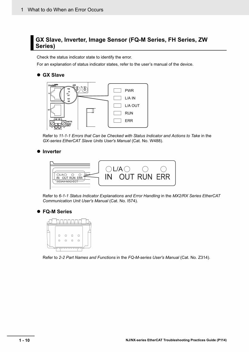
Check the status indicator state to identify the error.
For an explanation of status indicator states, refer to the user’s manual of the device.
GX Slave
Refer to 11-1-1 Errors that Can be Checked with Status Indicator and Actions to Take in the GX-series EtherCAT Slave Units User's Manual (Cat. No. W488).
Inverter
Refer to 6-1-1 Status Indicator Explanations and Error Handling in the MX2/RX Series EtherCAT Communication Unit User's Manual (Cat. No. I574).
FQ-M Series
Refer to 2-2 Part Names and Functions in the FQ-M-series User's Manual (Cat. No. Z314).
GX Slave, Inverter, Image Sensor (FQ-M Series, FH Series, ZW Series)
PWR
L/A IN
L/A OUT
RUN
ERR
1 - 10 NJ/NX-series EtherCAT Troubleshooting Practices Guide (P114)

1 What to do When an Error Occurs1-2 C
heckin
g th
e Un
it Sta
tus b
y th
e Ind
icators
1
1-2-3 C
hecking an Error that O
ccurs on a Slave
FH Series
Refer to 7.4.1 Checking the EtherCAT Communications in the EtherCAT Connection Guide Vision System (FH-series) (Cat. No. P577).
ZW Series
Refer to 2-2 Part Names and Functions in the ZW-series User's Manual (Cat. No. Z332).
Follow the troubleshooting procedure for the slave to identify the error.
Non-OMRON slaves
1 - 11NJ/NX-series EtherCAT Troubleshooting Practices Guide (P114)

1 What to do When an Error Occurs
1-3 Checking Event Information to Iden-tify the Error
Troubleshooting functions are provided by the Sysmac Studio. You can use the troubleshooting func-tions to identify errors that occur in a Controller, and reset the errors.
If the error occurs while the Sysmac Studio is online with the CPU Unit, the Sysmac Studio notifies the user of the error in the Controller Status Pane. From there, you can open the Troubleshooting and Event Logs Window to read detailed error information and troubleshooting methods.
Click the Troubleshooting Button in the toolbar, or select Troubleshooting from the Tools Menu.
The Sysmac Studio automatically collects the Controller’s error information, and opens the Trouble-shooting Window.
1-3-1 Event Logs with the Sysmac Studio
Displaying Errors on the Sysmac Studio
1 - 12 NJ/NX-series EtherCAT Troubleshooting Practices Guide (P114)

1 What to do When an Error Occurs1-3 C
heckin
g E
vent In
form
ation
to
Iden
tify the E
rror
1
1-3-1 E
vent Logs w
ith the S
ysmac S
tudio
Checking Current Errors with the Sysmac StudioYou can click the Controller Errors Tab in the Troubleshooting Window to read information on cur-rent errors in the Controller.
The Controller Errors Tab Page lists the current errors in order of their levels.
You can click the column headings in the Controller error list, such as the Level or Source, to reorder the table rows according to that heading. For example, the following change occurs when you click the Source heading.
Before Source heading is clicked.
After Source heading is clicked.
Checking Current Errors and the Event Logs with the Sysmac Studio
Display item DescriptionLevel This is the event level of the error.Source and Source Details This is the physical location and functional location of the error.Event Name Error nameEvent Code This is the code of the error.
1 - 13NJ/NX-series EtherCAT Troubleshooting Practices Guide (P114)

1 What to do When an Error Occurs
Displaying Event Logs with the Sysmac StudioWith Sysmac Studio, you can check a log of the Controller events that previously occurred on the Controller Event Log Tab Page.
You can select the event logs and levels to display in the Display Settings Area. Information on the events that you specify are displayed in the detailed information area.
1 - 14 NJ/NX-series EtherCAT Troubleshooting Practices Guide (P114)
1 What to do When an Error Occurs1-3 C
heckin
g E
vent In
form
ation
to
Iden
tify the E
rror
1
1-3-1 E
vent Logs w
ith the S
ysmac S
tudio
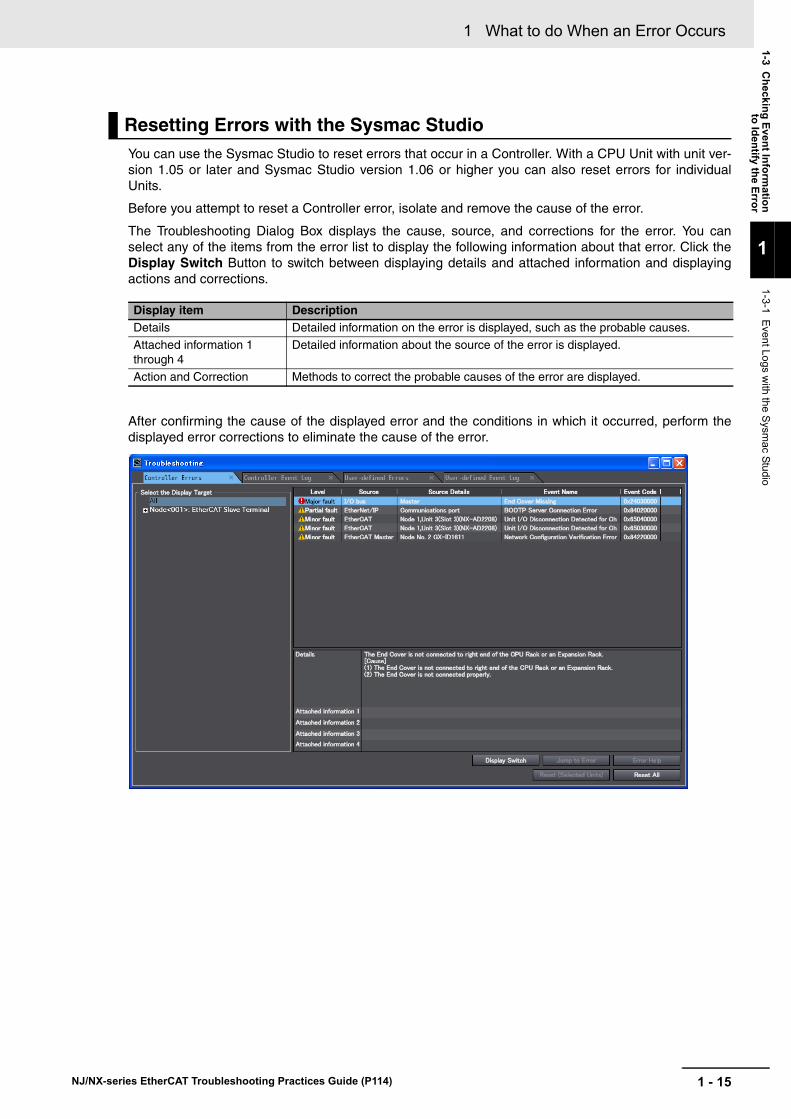
You can use the Sysmac Studio to reset errors that occur in a Controller. With a CPU Unit with unit ver-sion 1.05 or later and Sysmac Studio version 1.06 or higher you can also reset errors for individual Units.
Before you attempt to reset a Controller error, isolate and remove the cause of the error.
The Troubleshooting Dialog Box displays the cause, source, and corrections for the error. You can select any of the items from the error list to display the following information about that error. Click the Display Switch Button to switch between displaying details and attached information and displaying actions and corrections.
After confirming the cause of the displayed error and the conditions in which it occurred, perform the displayed error corrections to eliminate the cause of the error.
Resetting Errors with the Sysmac Studio
Display item DescriptionDetails Detailed information on the error is displayed, such as the probable causes.
Attached information 1 through 4
Detailed information about the source of the error is displayed.
Action and Correction Methods to correct the probable causes of the error are displayed.
1 - 15NJ/NX-series EtherCAT Troubleshooting Practices Guide (P114)
1 What to do When an Error Occurs
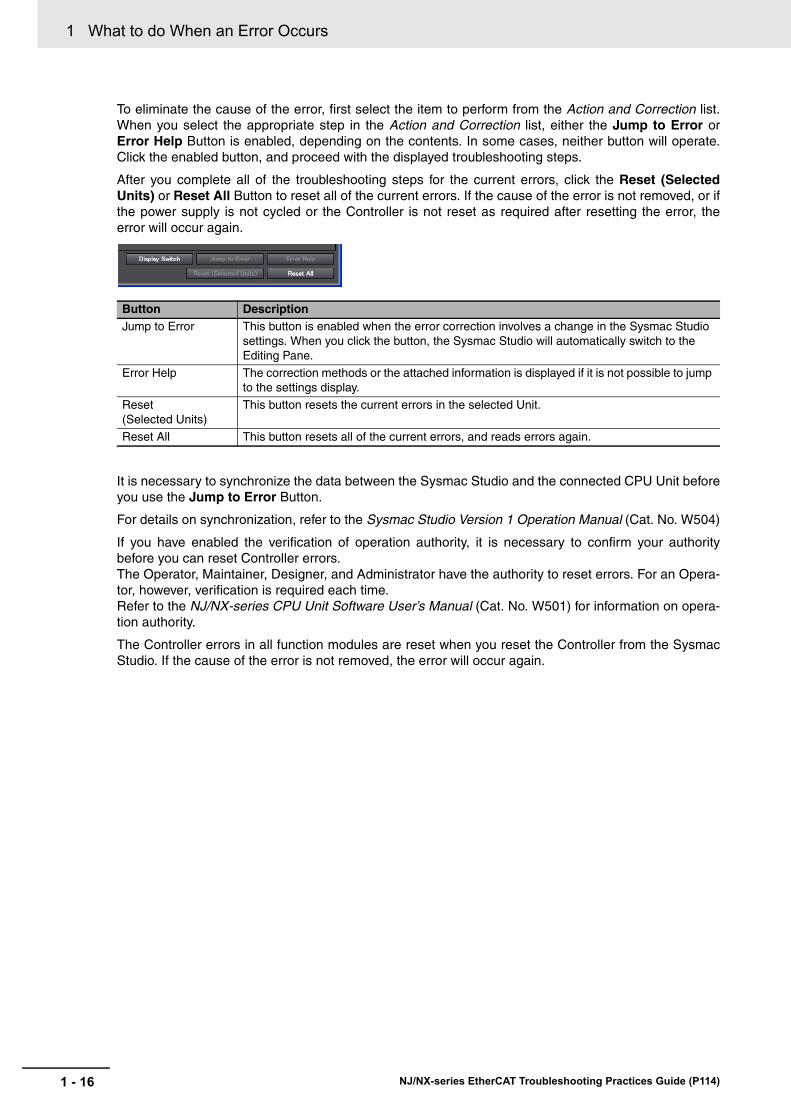
To eliminate the cause of the error, first select the item to perform from the Action and Correction list. When you select the appropriate step in the Action and Correction list, either the Jump to Error or Error Help Button is enabled, depending on the contents. In some cases, neither button will operate. Click the enabled button, and proceed with the displayed troubleshooting steps.
After you complete all of the troubleshooting steps for the current errors, click the Reset (Selected Units) or Reset All Button to reset all of the current errors. If the cause of the error is not removed, or if the power supply is not cycled or the Controller is not reset as required after resetting the error, the error will occur again.
It is necessary to synchronize the data between the Sysmac Studio and the connected CPU Unit before you use the Jump to Error Button.
For details on synchronization, refer to the Sysmac Studio Version 1 Operation Manual (Cat. No. W504)
If you have enabled the verification of operation authority, it is necessary to confirm your authority before you can reset Controller errors. The Operator, Maintainer, Designer, and Administrator have the authority to reset errors. For an Opera-tor, however, verification is required each time.Refer to the NJ/NX-series CPU Unit Software User’s Manual (Cat. No. W501) for information on opera-tion authority.
The Controller errors in all function modules are reset when you reset the Controller from the Sysmac Studio. If the cause of the error is not removed, the error will occur again.
Button DescriptionJump to Error This button is enabled when the error correction involves a change in the Sysmac Studio
settings. When you click the button, the Sysmac Studio will automatically switch to the Editing Pane.
Error Help The correction methods or the attached information is displayed if it is not possible to jump to the settings display.
Reset (Selected Units)
This button resets the current errors in the selected Unit.
Reset All This button resets all of the current errors, and reads errors again.
1 - 16 NJ/NX-series EtherCAT Troubleshooting Practices Guide (P114)

1 What to do When an Error Occurs1-3 C
heckin
g E
vent In
form
ation
to
Iden
tify the E
rror
1
1-3-2 C
hecking the Error on the H
MI (N
A) (N
J/NX
Trouble
shooting Screen
)
Whether the HMI Troubleshooter can be used depends on the combination of the HMI and the CPU Unit.
The models of HMIs on which the Troubleshooter can be used are given in the following table.
Whether the Troubleshooter can be used for specific system versions of the above HMI models is given in the following table.
Precautions for Correct Use
For the HMIs on which the NJ/NX Troubleshooting Screen can be used and details on HMI and CPU Unit combinations, refer to the NJ/NX-series Troubleshooting Manual (Cat. No. W503).
There are three methods to start up the NJ/NX Troubleshooter as described below.
1 Select “NJ/NX Troubleshooter” from “Project System Menu”.
1-3-2 Checking the Error on the HMI (NA) (NJ/NX Troubleshooting Screen)
Combinations of HMIs and CPU Units That Enable Using the Trou-bleshooter
HMI Model
NA5 NA5-
HMI system versionConnected CPU Unit
NX-series CPU Unit NJ-series CPU Unit
Version 1.02 or higher Can be used.
Version 1.01 or lower The HMI does not have a Troubleshooter.
Procedure to Start Up the NJ/NX Troubleshooter
1 - 17NJ/NX-series EtherCAT Troubleshooting Practices Guide (P114)
1 What to do When an Error Occurs
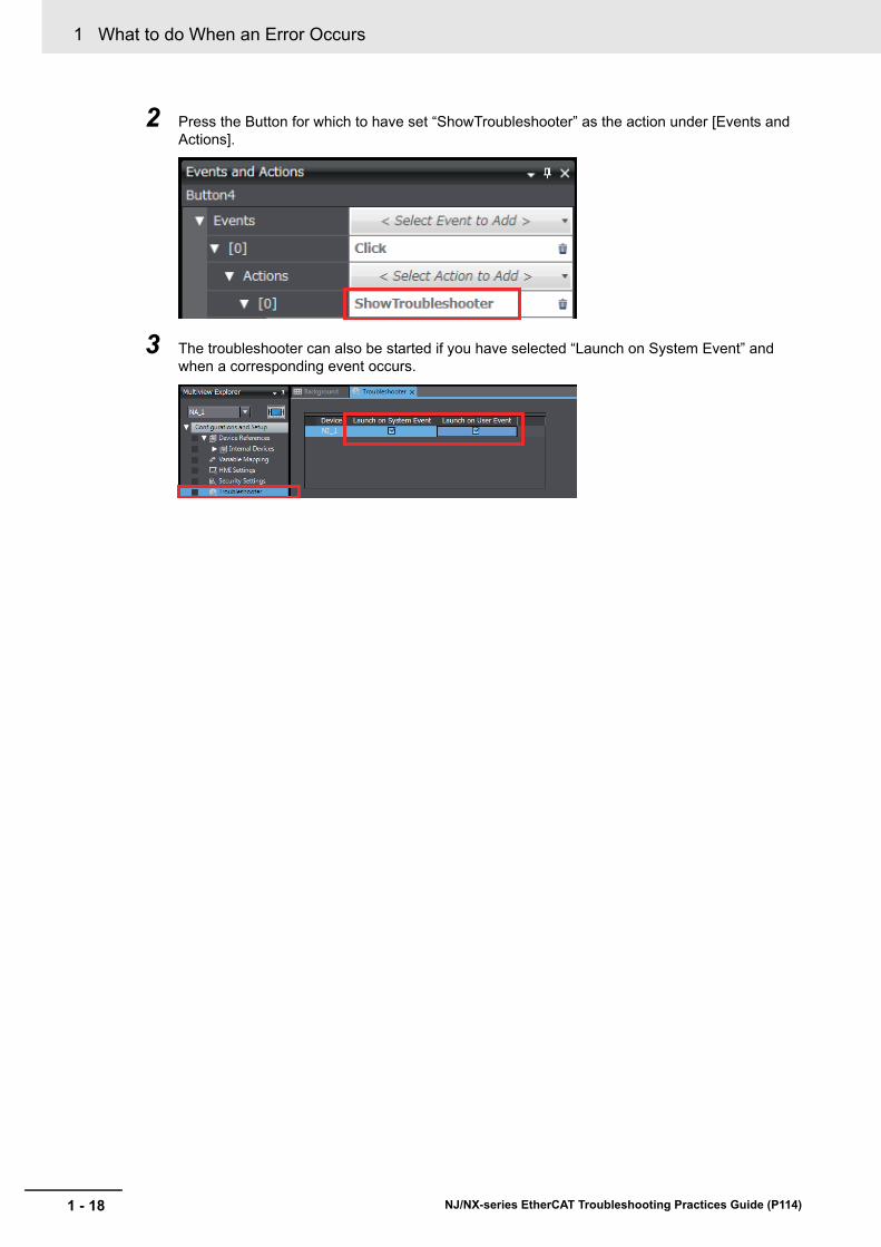
2 Press the Button for which to have set “ShowTroubleshooter” as the action under [Events and Actions].
3 The troubleshooter can also be started if you have selected “Launch on System Event” and when a corresponding event occurs.
1 - 18 NJ/NX-series EtherCAT Troubleshooting Practices Guide (P114)

1 What to do When an Error Occurs1-3 C
heckin
g E
vent In
form
ation
to
Iden
tify the E
rror
1
1-3-2 C
hecking the Error on the H
MI (N
A) (N
J/NX
Trouble
shooting Screen
)
Displays the currently raised “Controller Events”.
“Error” appears when the error has occurred.
“Normal” is displayed in the normal status.
To confirm the contents of the currently raised errors, select the controller (to highlight it light blue) and press “Show Controller Events”.
Active Events - Controller Events
When "Error" appears in the Controller Event Status column on the "Active Events" tab, it means that the error has occurred in the controller. Check for the currently occurring errors following the procedure below.
1 When "Error" is displayed in the Controller Event Status column on the "Active Events" tab, press the "Show Controller Events" button at the bottom of the screen.
Active Events
1 - 19NJ/NX-series EtherCAT Troubleshooting Practices Guide (P114)

1 What to do When an Error Occurs
2 The screen is switched to "Controller Events". A list of the currently occurring controller events is displayed. Select an event from the list and press "Show Detail" at the right bottom of the screen.
3 The details of the event that is selected in Step 2 appear.
You can recover from the problem by referring to what is displayed in "Detailed Information".
4 In Steps 2 and 3, if you press the "Screen Shot" button, the currently displayed screen can be captured and saved in an SD Memory Card.
When no SD Memory Card is inserted in NA, if you press "Yes" in the dialog box shown on the right, the following message appears.
"Failed to capture screenshot - Could not find the storage media 'SDCard'."
1 - 20 NJ/NX-series EtherCAT Troubleshooting Practices Guide (P114)

1 What to do When an Error Occurs1-3 C
heckin
g E
vent In
form
ation
to
Iden
tify the E
rror
1
1-3-2 C
hecking the Error on the H
MI (N
A) (N
J/NX
Trouble
shooting Screen
)
Displays the "Controller Events" that have been raised so far.
"Yes" appears when the event log is not cleared."No" appears when it is cleared.
To confirm the contents of the errors that have been raised so far, select the controller (to highlight it light blue) and press “Show Controller Events”.
Event Logs - Controller Events
When "Yes" appears in the Controller Event Status column on the "Event Logs" tab, it means that there is a log of the errors that have occurred so far in the controller. Check for the log following the procedure below.
1 When "Yes" is displayed in the Controller Event Status column on the "Event Logs" tab, press the "Show Controller Events" button at the bottom of the screen.
Event Logs
1 - 21NJ/NX-series EtherCAT Troubleshooting Practices Guide (P114)

1 What to do When an Error Occurs
2 The screen is switched to "Controller Events". A list of the controller events that have occurred so far is displayed. Select an event from the list and press "Show Detail" at the right bottom of the screen.
3 The details of the event that is selected in Step 2 appear.
You can recover from the problem by referring to what is displayed in "Detailed Information".
1 - 22 NJ/NX-series EtherCAT Troubleshooting Practices Guide (P114)

1 What to do When an Error Occurs1-3 C
heckin
g E
vent In
form
ation
to
Iden
tify the E
rror
1
1-3-3 C
hecking the Error on the H
MI (N
S) (N
S T
roubleshooting S
creen)
You can connect an NS-series HMI to an NJ/NX-series CPU Unit through an EtherNet/IP network, and use it to read and reset errors that occurred in the Controller. (The Troubleshooter of the HMI is used.)
To perform troubleshooting from an HMI, connect the HMI to the built-in EtherNet/IP port on the CPU Unit.
Whether the HMI Troubleshooter can be used depends on the combination of the HMI and the CPU Unit.
The models of HMIs on which the Troubleshooter can be used are given in the following table.
Whether the Troubleshooter can be used for specific system versions of the above HMI models is given in the following table.
Precautions for Correct Use
For the HMI on which the NJ/NX Troubleshooting Screen can be used and details on display and CPU Unit combinations, refer to the NJ/NX-series Troubleshooting Manual (Cat. No. W503).
1-3-3 Checking the Error on the HMI (NS) (NS Troubleshooting Screen)
Combinations of HMIs and CPU Units That Enable Using the Trou-bleshooter
HMI Model
NS8, NS10, NS12, and NS15 NS-T01-V2 (The V2 versions have an Ethernet port.)
NS5 NS5-Q11-V2 (These models have expanded memory and an Ethernet port.)
NSJ8, NSJ10, and NSJ12 All models
NSJ5 NSJ5-Q11- (These models have expanded memory and an Ethernet port.)
HMI system versionConnected CPU Unit
NX-series CPU Unit NJ-series CPU Unit
Version 8.9 or higher Can be used.
Version 8.5 to 8.8 Cannot be used. Can be used.
Ver. 8.4 or lower The HMI does not have a Troubleshooter.
1 - 23NJ/NX-series EtherCAT Troubleshooting Practices Guide (P114)

1 What to do When an Error Occurs
You can check for errors in the Controller using the Troubleshooter of an HMI. You can also use the Troubleshooter to read detailed error information and corrections for current errors.
Refer to the relevant HMI manual for details on the HMI Troubleshooter.
The following example demonstrates the procedure used to check for errors with an NS8, NS10, NS12, or NS15 HMI.
You can check the event source in the Function Module View of the Troubleshooter. If you click the Select Button for a function module in the Event source Table, you can display the Source details for events for that function module. You can select the list in the Source details Table to display the List View.
The List View displays a list of the errors produced by the event source that you selected in the Function Module View.
Checking for Current Errors with an HMI
1 - 24 NJ/NX-series EtherCAT Troubleshooting Practices Guide (P114)

1 What to do When an Error Occurs1-3 C
heckin
g E
vent In
form
ation
to
Iden
tify the E
rror
1
1-3-3 C
hecking the Error on the H
MI (N
S) (N
S T
roubleshooting S
creen)
You can use the Troubleshooter in an HMI to reset errors that occur in the Controller. Before you attempt to reset a Controller error, isolate and remove the cause of the error.
The following example demonstrates the procedure used to check for errors with an NS8, NS10, NS12, or NS15 HMI.
Click the Select Button in the List View to display information such as the error’s causes and correc-tions. If you selected the Detail View for the error, the display shows the error’s cause and corrections. After you confirm the cause of the displayed error and the conditions in which it occurred, perform the steps in the displayed correction.
After you complete all of the correction steps for the current errors, click the Reset error Button to reset all of the current errors. If the cause of the error is not removed, or if the power supply is not cycled or the Controller is not reset as required after resetting the error, the error will occur again.
In order to reset the Controller errors, it is necessary to confirm your rights according to the operation authority settings for the Troubleshooter. Refer to the relevant HMI manual for details on operation authorities.
Resetting Errors with an HMI
1 - 25NJ/NX-series EtherCAT Troubleshooting Practices Guide (P114)

1 What to do When an Error Occurs
In an NJ/NX-series Controller, you can check for errors that have occurred from the user program. This feature allows you to program operations in the user program according to the error status. Special instructions are provided for this purpose. These include instructions to get Controller error information and instructions to reset Controller errors.
Determine the error status with the instruction to get error information that is provided for each function module. The following table lists the instruction that are used to get error information for each function module.
Refer to the NJ/NX-series Instructions Reference Manual (Cat. No. W502) for details on these instruc-tions.
Example of Error Detection for the EtherCAT Master Function Module
1-3-4 Checking the Error from a Program (Get Error Status Instruction)
Instructions That Get Controller Error Information
Instruction name Instruction Function
Get PLC Controller Error Status GetPLCError Gets the status and the event code of the error with the highest level of the Controller errors in the PLC Function Module.
Get EtherCAT Error Status GetECError Gets the status and the event code of the error with the highest level of the communications port errors and mas-ter errors detected by the EtherCAT Master Function Mod-ule.
Get Motion Control Error Status GetMCError Gets the highest level status (partial fault or minor fault) and highest level event code of the current Controller errors in the Motion Control Function Module.
Name Data type Initial value Comment
Trigger BOOL FALSE Get Condition
EC_Error BOOL FALSE EtherCAT Master Error Flag
Trigger
defghi
EC_ErrorGetECErrorEN
LevelCode
1 - 26 NJ/NX-series EtherCAT Troubleshooting Practices Guide (P114)

1 What to do When an Error Occurs1-3 C
heckin
g E
vent In
form
ation
to
Iden
tify the E
rror
1
1-3-4 C
hecking the Error from
a Pro
gram (G
et Error S
tatus Instru
ction)
You can use the instructions that are provided to reset errors in the user program to reset errors that occur in the Controller. Before you attempt to reset a Controller error, isolate and remove the cause of the error. Reset the errors with the instruction provided to reset errors for each function module.
Refer to the NJ/NX-series Instructions Reference Manual (Cat. No. W502) for details on these instruc-tions.
Resetting Controller Errors with Instructions
Instruction name Instruction FunctionReset PLC Controller Error ResetPLCError Resets current Controller errors from the PLC Function
Module.Reset EtherCAT Error ResetECError Resets current Controller errors from the EtherCAT Mas-
ter Function Module.
1 - 27NJ/NX-series EtherCAT Troubleshooting Practices Guide (P114)

1 What to do When an Error Occurs
This information identifies where an event occurred in the Controller. The event sources are given below for Controller events and user-defined events.
Sources of Controller Events
Controller events occur in the function modules in the CPU Unit.
For some function modules, there is more detailed information about the event source. This informa-tion is called the detailed event source.
The following are Controller events.
Sources of User-defined Events
User-defined events occur in the PLC Function Module.
This information displays the category of event log. It is used to access error logs from the Sysmac Stu-dio or an HMI.
Each event log can contain the following number of records. If the number of events exceeds the num-ber of records permitted, the CPU Unit overwrites the oldest events.
1-3-5 Detailed Information on Event Logs
Event Sources
Event source Source details
PLC Function Module I/O bus master or CJ-series Unit*1
*1. The source details information does not show information from the error histories from within CJ-series CPU Special Units or EtherCAT slaves. Read the error histories from the appropriate Support Software.
Motion Control Function Module Common, axis, or axes group
EtherCAT Master Function Module Communications port, EtherCAT master, or EtherCAT slave
EtherNet/IP Function Module Communications port/communications port 1/communica-
tions port 2, CIP/CIP1/CIP2, FTP, NTP, or SNMP
Category
Event type Event log category Description
Controller events System log The Controller automatically detects and records these events. CJ-series Unit errors are also included.
Access log This is a record of events that have affect Controller operation due to user actions.
User-defined events User event log This is a log of events that are defined by the user.
Number of Records
Event type Event log category Maximum number of records
Controller events System log NX701-: 2,048 events,
NJ501-: 1,024 events,
NJ301-: 512 events,
NJ101-: 512 events
Access log
User-defined events User event log
1 - 28 NJ/NX-series EtherCAT Troubleshooting Practices Guide (P114)
1 What to do When an Error Occurs1-3 C
heckin
g E
vent In
form
ation
to
Iden
tify the E
rror
1
1-3-5 D
etailed Inform
ation on Event Log
s
The NJ/NX-series CPU Unit uses a Battery to retain the event logs when the power is interrupted.
Precautions for Correct Use
The event logs are retained by Battery. They are not retained when there is no Battery.
Periodically export event logs as required.
Event codes are assigned to Controller events by the system in advance according to the type of event. Event codes are assigned to user-defined events by the user. Controller event codes are 8-digit hexa-decimal values. You can use the Get Error Status instruction to read the error codes of current errors. You can assign a decimal number from 1 to 60,000 as the event code for a user-defined event.
Retaining Events during Power Interruptions
Event Codes
1 - 29NJ/NX-series EtherCAT Troubleshooting Practices Guide (P114)
1 What to do When an Error Occurs
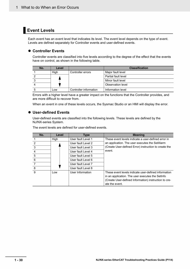
Each event has an event level that indicates its level. The event level depends on the type of event. Levels are defined separately for Controller events and user-defined events.
Controller Events
Controller events are classified into five levels according to the degree of the effect that the events have on control, as shown in the following table.
Errors with a higher level have a greater impact on the functions that the Controller provides, and are more difficult to recover from.
When an event in one of these levels occurs, the Sysmac Studio or an HMI will display the error.
User-defined Events
User-defined events are classified into the following levels. These levels are defined by the NJ/NX-series System.
The event levels are defined for user-defined events.
Event Levels
No. Level Classification1 High Controller errors Major fault level
2 Partial fault level
3 Minor fault level
4 Observation level
5 Low Controller information Information level
No. Level Type Meaning1 High User fault Level 1 These event levels indicate a user-defined error in
an application. The user executes the SetAlarm (Create User-defined Error) instruction to create the event.
2 User fault Level 2
3 User fault Level 3
4 User fault Level 4
5 User fault Level 5
6 User fault Level 6
7 User fault Level 7
8 User fault Level 8
9 Low User Information These event levels indicate user-defined information in an application. The user executes the SetInfo (Create User-defined Information) instruction to cre-ate the event.
1 - 30 NJ/NX-series EtherCAT Troubleshooting Practices Guide (P114)

1 What to do When an Error Occurs1-3 C
heckin
g E
vent In
form
ation
to
Iden
tify the E
rror
1
1-3-5 D
etailed Inform
ation on Event Log
s
The Sysmac Studio or an HMI displays two event logs: the Controller event log and the user-defined event log. The Controller logs include both the access log and the system log.
The Sysmac Studio can also display the error logs that are recorded in the CJ-series Units and Ether-CAT slaves.
The events in these logs are displayed in tables on the Sysmac Studio. Select an event from the table to display detailed information.
Additional Information
If an event occurs in the Controller that is not supported by the version of the Sysmac Studio or an HMI, the source is displayed as “Unknown” and the event name is displayed as “Unknown Event.” The event code and attached information are displayed correctly.
Displaying Event Logs
1 - 31NJ/NX-series EtherCAT Troubleshooting Practices Guide (P114)

1 What to do When an Error Occurs
Clearing Event Logs from the Sysmac Studio or an HMI
You can clear the event logs from the Sysmac Studio or from an HMI. You can clear the Controller event log and user-defined event log separately.
Precautions for Correct Use
• If you need to delete event log in the CPU Unit from the Sysmac Studio or an HMI, make sure you do not need any of the event information before you delete the event log. You may have overlooked some important information and observation level Controller events or user-defined events. Always check for these before you delete an event log.
• Refer to the NJ/NX-series Troubleshooting Manual (Cat. No. W503) for restrictions on clear-ing an event log from the PT.
Clearing Event Logs with the Clear All Memory Operation
When you perform the Clear All Memory operation for an NJ/NX-series CPU Unit from the Sysmac Studio, you can select whether to clear the event logs.
You can use the Sysmac Studio or an HMI to export the displayed event log to a CSV file.
Clearing Event Logs
Exporting Event Logs
1 - 32 NJ/NX-series EtherCAT Troubleshooting Practices Guide (P114)

1 What to do When an Error Occurs1-4 C
heckin
g E
rrors U
sing
the
Co
mm
un
ication
s Statu
s
1
1-4 Checking Errors Using the Communi-cations Status
The diagnostic and statistical information provides statistics on the number of communications frames sent and received by the EtherCAT master and EtherCAT slaves as well as the number of frames for which errors were detected.
You can use it to diagnosis the EtherCAT network line qualify for the following:
• Confirming that the EtherCAT network was correctly installed during a test run
• Finding the causes of communications errors that occur during normal operation
• Checking the EtherCAT network line quality during normal operation
You can identify an EtherCAT error by diagnosing the communication state of the EtherCAT master or EtherCAT slave from diagnostic and statistical information.
EtherCAT Network Diagnostic Procedure
Use master diagnostic and statistical information and slave diagnostic and statistical information to diagnose the EtherCAT network as follows.
If the diagnostic results show that the EtherCAT network is not operating normally, you can find the location of the error.
An outline procedure from EtherCAT network diagnosis through correction is given below.
1 Acquire the diagnostic and statistical information for the master and slaves.
2 Check for errors in the trends shown in the master diagnostic and statistical information.
3 Find the locations of the errors with trends in the slave diagnostic and statistical information.
4 Implement corrections for the error locations that you found.
5 Confirm status after implementation of the correction.
1 - 33NJ/NX-series EtherCAT Troubleshooting Practices Guide (P114)

1 What to do When an Error Occurs
There are two methods to acquire the diagnostic and statistical information for the master and slaves. The following table describes each method. Use either of the methods to acquire the diagnostic and statistical information for the master and slaves.
Precautions for Correct Use
When the Sysmac Studio’s diagnostic and statistical information display is used, the maximum number of error frames recorded for the slave diagnostic and statistical information is 255. If the number of error frames exceeds 255, increasing trends of the number of error frames cannot be recognized. If the number of error frames for the slave diagnostic and statistical information is assumed to exceed 255, execute the clear operation for the slave diagnostic and statistical infor-mation before acquiring the slave diagnostic and statistical information.
1-4-1 Getting Diagnostic/Statistical Information
Acquisition method DescriptionRefer-ence
Using the diagnostic and sta-tistical information display of Sysmac Studio
Use the Sysmac Studio to acquire the diagnostic and statistical infor-mation. You can save the acquired diagnostic and statistical informa-tion as a CSV file on the computer.
P. 1-42
Using the diagnosis/statistics log of CPU Unit
The CPU Unit acquires the diagnostic and statistical information peri-odically. The acquired diagnostic and statistical information is saved in an SD Memory Card that is mounted on the CPU Unit.
P. 1-49
1 - 34 NJ/NX-series EtherCAT Troubleshooting Practices Guide (P114)

1 What to do When an Error Occurs1-4 C
heckin
g E
rrors U
sing
the
Co
mm
un
ication
s Statu
s
1
1-4-2 C
hecking for Errors U
sing Master D
iagnostic and S
tatistical Information
Check for trends in the items in the acquired master diagnostic and statistical information to diagnose errors in the EtherCAT network.
Example of the Master Diagnosis/Statistics Tab Page of Sysmac Studio
If the value of the frame reception timeout count or number of CRC error frames received increases, then the EtherCAT network is not operating normally.
If a certain number of the frame reception timeout count or a certain number of CRC error frames received is detected, the EtherCAT network may not be operating normally.
If there is the error or possibility of the error in the EtherCAT network, find the error location by perform-ing 1-4-3 Finding Locations of Errors Using the Slave Diagnostic and Statistical Information on page 1-36.
Additional Information
A certain number of the frame reception timeout count or a certain number of CRC error frames received is also detected if a power OFF or disconnection occurs in an EtherCAT slave.
1-4-2 Checking for Errors Using Master Diagnostic and Statistical Information
Increased.
Increased.
1 - 35NJ/NX-series EtherCAT Troubleshooting Practices Guide (P114)

1 What to do When an Error Occurs
You can check for trends of values in the slave diagnostic and statistical information to find the locations of the errors.
Example of the Slave Diagnosis/Statistics Tab Page of Sysmac Studio
The following are the points to check to find error locations based on the number of error frames.
• A certain number of error frames is detected.
• The number of error frames is increased compared to the value acquired last time.
• Failed is displayed for the number of error frames.
If a certain number of error frames is detected for more than one port, start finding error locations from the port with the highest number of error frames.
The error locations that you find will change depending on the configuration of EtherCAT slave con-nection. Refer to the network configuration diagram to find error locations.
This section explains how to find error locations with two examples of EtherCAT network configura-tions in which the EtherCAT slave connection configurations are different.
1-4-3 Finding Locations of Errors Using the Slave Diagnostic and Sta-tistical Information
1 - 36 NJ/NX-series EtherCAT Troubleshooting Practices Guide (P114)

1 What to do When an Error Occurs1-4 C
heckin
g E
rrors U
sing
the
Co
mm
un
ication
s Statu
s
1
1-4-4 Identifying the C
ause of the E
rror
Examples of Finding Error Locations
Example 1: Network Configuration Where an EtherCAT Junction Slave Is Not Used
Network configuration
Slave Diagnosis/Statistics Tab Page
The number of error frames for the input port (PortA) for node address 4 is 31, so you can see that error frames were received on the input port for node address 4.
Therefore, you can assume that there is a problem between the output port (PortB) for node address 3 and the input port for node address 4.
This corresponds to location (A), (B) or (C) in the network configuration diagram.
Concretely, you can assume the following possible error locations.
• The device at node address 3
• The cable between the output port at node address 3 and the input port at node address 4 or the connectors at those ports
• The device at node address 4
1-4-4 Identifying the Cause of the Error
IN OUTOUT OUTIN ININ OUT
(B)(A)
NJ/NX-series CPU Unit
EtherCAT master (C)
Slavenode address 64
Slavenode address 3
Slavenode address 4
Slavenode address 5
1 - 37NJ/NX-series EtherCAT Troubleshooting Practices Guide (P114)

1 What to do When an Error Occurs
Example 2: Network Configuration Where an EtherCAT Junction Slave Is Used
Network configuration
Slave Diagnosis/Statistics Tab Page
The number of error frames for the input port (PortA) for node address 4 is 123, so you can see that error frames were received on the input port for node address 4.
Therefore, you can assume that there is a problem between the output port (X3) for node address 64 and the input port for node address 4.
This corresponds to location (A), (B) or (C) in the network configuration diagram.
Concretely, you can assume the following possible error locations.
• The device at node address 64
• The cable between the output port at node address 64 and the input port at node address 4 or the connectors at those ports
• The device at node address 4
EtherCAT master
Slavenode address 4
Slavenode address 3
Slavenode address 5
IN
OUT
IN
OUT
INOUT
IN
OUT
(A)
(B)
NJ/NX-series CPU Unit
Junction slavenode address 64
(C)
1 - 38 NJ/NX-series EtherCAT Troubleshooting Practices Guide (P114)

1 What to do When an Error Occurs1-4 C
heckin
g E
rrors U
sing
the
Co
mm
un
ication
s Statu
s
1
1-4-4 Identifying the C
ause of the E
rror
This is the procedure to find error locations when Failed is displayed for the number of error frames.
In the EtherCAT network configuration, Failed is sometimes displayed for more than one Ether-CAT slave.
In the network configuration for example 2, assume that Failed is displayed for the number of error frames for node addresses 4 and 5.
If Failed is displayed for the number of error frames, the EtherCAT slave currently cannot com-municate. If an EtherCAT slave cannot communicate, all of the EtherCAT slaves connected after it may not be able to communicate. In the network configuration diagram of example 2, node address 5 is connected after node address 4.
Therefore, you can assume that there is the Error in node address 4 that prevents communica-tions.
Concretely, you can assume the following possible error locations.
• The device at node address 64
• The cable between the output port at node address 64 and the input port at node address 4 or the connectors at those ports
• The device at node address 4
1 - 39NJ/NX-series EtherCAT Troubleshooting Practices Guide (P114)

1 What to do When an Error Occurs
Implement corrections for the error locations that you found.
To check the position of the EtherCAT slave with the error in the network configuration, refer to the Node Address|Network configuration display under Slave Diagnosis/Statistics.
The following table provides corrections for the causes as assumed from the diagnostic and statistical information.
The following is a description of the case which does not correspond to any of above conditions.
If a certain number of the frame reception timeout count and CRC error frames received for the master diagnostic and statistical information, as well as a certain number of error frames for the slave diagnos-tic and statistical information are detected but are not increasing, these numbers were detected tempo-rarily due to any of the following error causes.
• A connector on the Ethernet cable is disconnected, the contact is faulty, or parts are faulty.
• There is noise.
• The Ethernet cable is broken or the specified cable was not used.
Implement corrections for the error locations that you found. Refer to the table above for what to do for corrections.
1-4-5 Identifying Causes and Taking Corrective Action
Master diagnosis and statistical information
trend
Slave diagnosis and sta-tistical information trend
Assumed error cause Possible correction
The frame reception timeout count is increasing.
The num-ber of CRC error frames received is not increas-ing.
Failed is displayed for the number of error frames for some slaves.
The power is not supplied to the EtherCAT slave.
Supply the power to the EtherCAT slave.
A connector on the Ether-net cable is disconnected, the contact is faulty, or parts are faulty.
Make sure the connector is mated correctly, or reconnect the connector.
The Ethernet cable is bro-ken or the specified cable was not used.
Replace the Ethernet cable.
A general-purpose Ether-net hub is connected.
Replace the general-pur-pose Ethernet hub with an EtherCAT Junction Slave.
The EtherCAT slave failed. Replace the EtherCAT slave.
The number of error frames is not increasing.
The EtherCAT master communications cycle is too short.
Go online with the Sys-mac Studio, lengthen the task period (communica-tions cycle), and set it in the CPU Unit again.
The num-ber of CRC error frames received is increasing.
Failed is displayed for the number of error frames and the number of error frames is increasing.
A connector on the Ether-net cable is disconnected, the contact is faulty, or parts are faulty.
Make sure the connector is mated correctly, or reconnect the connector.
The EtherCAT slave failed. Replace the EtherCAT slave.
Failed is displayed for the number of error frames or the number of error frames is increasing.
There is noise. Implement noise counter-measures.
1 - 40 NJ/NX-series EtherCAT Troubleshooting Practices Guide (P114)
1 What to do When an Error Occurs1-4 C
heckin
g E
rrors U
sing
the
Co
mm
un
ication
s Statu
s
1
1-4-6 C
onfirmation A
fter Corrective A
ction
To confirm that the error locations were corrected, perform 1-4-2 Checking for Errors Using Master Diagnostic and Statistical Information on page 1-35 again to make sure the network is operating nor-mally.
1-4-6 Confirmation After Corrective Action
1 - 41NJ/NX-series EtherCAT Troubleshooting Practices Guide (P114)

1 What to do When an Error Occurs
This section describes how to activate the diagnostic and statistical information display of Sysmac Stu-dio. The functions of the operation buttons and displayed items are also explained.
ActivationActivate the diagnostic and statistical information display of Sysmac Studio as follows.
1 Start the Sysmac Studio and go online with the Controller.
2 Double-click EtherCAT under Configurations and Setup in the Multiview Explorer. Or, right-click EtherCAT under Configurations and Setup and select Edit.
1-4-7 Diagnostic and Statistical Information Display of Sysmac Studio
1 - 42 NJ/NX-series EtherCAT Troubleshooting Practices Guide (P114)

1 What to do When an Error Occurs1-4 C
heckin
g E
rrors U
sing
the
Co
mm
un
ication
s Statu
s
1
1-4-7 D
iagnostic and S
tatistical Informatio
n Display of S
ysmac S
tudio
3 Right-click the EtherCAT master on the EtherCAT Tab Page and select Display Diagnosis/Statistics Information from the menu.
The diagnostic and statistical information for the master and slaves are displayed.
1 - 43NJ/NX-series EtherCAT Troubleshooting Practices Guide (P114)

1 What to do When an Error Occurs
Operation Button FunctionsThe following table describes the buttons to operate the diagnostic and statistical information.
*1 Only for the EtherCAT slaves that are registered in the network configuration information of the project.
*2 If the number of error frames exceeds 255, 255 is output.
Version Information
A CPU Unit with unit version 1.11 or later and Sysmac Studio version 1.15 or higher are required to use the Clear Slave Diagnosis/Statistics Information Button.
Button Function
Get Acquires the diagnostic and statistical information from the EtherCAT master
and EtherCAT slaves*1 and updates the display.
You can retain a maximum of 100 diagnostic and statistical data that you acquired.
When the Display Diagnosis/Statistics Information Tab Page is closed, the diagnostic and statistical information that you acquired are discarded.
Clear Master Diagnosis/Sta-tistics Information
Clears all values of the master diagnostic and statistical information to zeros.
Clear Slave Diagnosis/Statis-tics Information
Clears all values of the slave diagnostic and statistical information to zeros.
Output File Outputs the diagnostic and statistical information to a CSV file in a specified folder. The following data are output.
• Master diagnostic and statistical information
• Slave diagnostic and statistical information *2
1 - 44 NJ/NX-series EtherCAT Troubleshooting Practices Guide (P114)

1 What to do When an Error Occurs1-4 C
heckin
g E
rrors U
sing
the
Co
mm
un
ication
s Statu
s
1
1-4-7 D
iagnostic and S
tatistical Informatio
n Display of S
ysmac S
tudio
Master Diagnostic and Statistical Information
The following are the items displayed for the master diagnostic and statistical information.
The last two master diagnostic and statistical data acquired from the EtherCAT master are dis-played. If the master diagnostic and statistical data is not acquired, “---” is displayed.
Precautions for Correct Use
• All values of the master diagnostic and statistical information are cleared to zeros when the power supply to the Controller is turned ON.
• The network propagation delay time is not cleared to zero when the master diagnostic and sta-tistical information is cleared.
• Values of the network propagation delay time and transmission cycle are valid only if an Ether-CAT slave that supports a distributed clock is assigned to the primary periodic task. If an Eth-erCAT slave that supports a distributed clock is not assigned to the primary periodic task, “---” is displayed.
• The items for PDO communications cycle 2 are valid only if an EtherCAT slave that supports a distributed clock is assigned to the priority-5 periodic task. If the CPU Unit does not have a pri-ority-5 periodic task or if an EtherCAT slave that supports a distributed clock is not assigned to the priority-5 periodic task, “---” is displayed.
Items that indicate the values may increase if the EtherCAT network is not operating normally.
Items that indicate the values may increase if the EtherCAT network is not operating normally.
1 - 45NJ/NX-series EtherCAT Troubleshooting Practices Guide (P114)
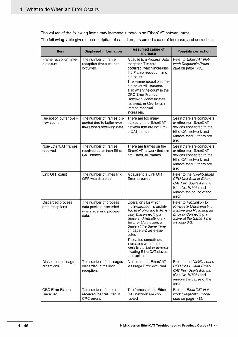
1 What to do When an Error Occurs
The values of the following items may increase if there is an EtherCAT network error.
The following table gives the description of each item, assumed cause of increase, and correction.
Item Displayed information Assumed cause of increase Possible correction
Frame reception time-out count
The number of frame reception timeouts that occurred.
A cause to a Process Data reception Timeout occurred, which increases the Frame reception time-out count.The Frame reception time-out count will increase also when the count in the CRC Error Frames Received, Short frames received, or Overlength frames received increases.
Refer to EtherCAT Net-work Diagnostic Proce-dure on page 1-33.
Reception buffer over-flow count
The number of frames dis-carded due to buffer over-flows when receiving data.
There are too many frames on the EtherCAT network that are not Eth-erCAT frames.
See if there are computers or other non-EtherCAT devices connected to the EtherCAT network and remove them if there are any.
Non-EtherCAT frames received
The number of frames received other than Ether-CAT frames.
There are frames on the EtherCAT network that are not EtherCAT frames.
See if there are computers or other non-EtherCAT devices connected to the EtherCAT network and remove them if there are any.
Link OFF count The number of times link OFF was detected.
A cause to a Link OFF Error occurred.
Refer to the NJ/NX-series CPU Unit Built-in Ether-CAT Port User’s Manual (Cat. No. W505) and remove the cause of the error.
Discarded process data receptions
The number of process data packets discarded when receiving process data.
Operations for which multi-execution is prohib-ited in Prohibition to Physi-cally Disconnecting a Slave and Resetting an Error or Connecting a Slave at the Same Time on page 3-2 were exe-cuted.
The value sometimes increases when the net-work is started or commu-nicating EtherCAT slaves are replaced.
Refer to Prohibition to Physically Disconnecting a Slave and Resetting an Error or Connecting a Slave at the Same Time on page 3-2.
Discarded message receptions
The number of messages discarded in mailbox reception.
A cause to an EtherCAT Message Error occurred.
Refer to the NJ/NX-series CPU Unit Built-in Ether-CAT Port User’s Manual (Cat. No. W505) and remove the cause of the error.
CRC Error Frames Received
The number of frames received that resulted in CRC errors.
The frames on the Ether-CAT network are cor-rupted.
Refer to EtherCAT Net-work Diagnostic Proce-dure on page 1-33.
1 - 46 NJ/NX-series EtherCAT Troubleshooting Practices Guide (P114)

1 What to do When an Error Occurs1-4 C
heckin
g E
rrors U
sing
the
Co
mm
un
ication
s Statu
s
1
1-4-7 D
iagnostic and S
tatistical Informatio
n Display of S
ysmac S
tudio
Precautions for Correct Use
Even if communications are normal, values other than 0 may occur for the frame reception time-out count and the number of CRC error frames received. Refer to EtherCAT Network Diagnostic Procedure on page 1-33 to determine if the EtherCAT network is operating normally.
Frame reception errors The number of frames resulting in reception errors from the Ethernet controller (EtherMAC).
The frames on the Ether-CAT network are cor-rupted due to noise.
Implement noise counter-measures.
Collision count The total number of delay collisions on the line after start of transmissions.
A repeater hub is con-nected.
You cannot use repeater hubs with EtherCAT com-munications. See if there are repeater hubs con-nected to the EtherCAT network and remove them if there are any.
Short frames received The number of frames received with less than 64 bytes.
The frames on the Ether-CAT network are cor-rupted due to noise. Computers or other non-EtherCAT devices are connected.
Refer to EtherCAT Net-work Diagnostic Proce-dure on page 1-33.
Overlength frames received
The number of frames received with more than 1,522 bytes.
The frames on the Ether-CAT network are cor-rupted due to noise. Computers or other non-EtherCAT devices are connected.
Refer to EtherCAT Net-work Diagnostic Proce-dure on page 1-33.
Item Displayed information Assumed cause of increase Possible correction
1 - 47NJ/NX-series EtherCAT Troubleshooting Practices Guide (P114)
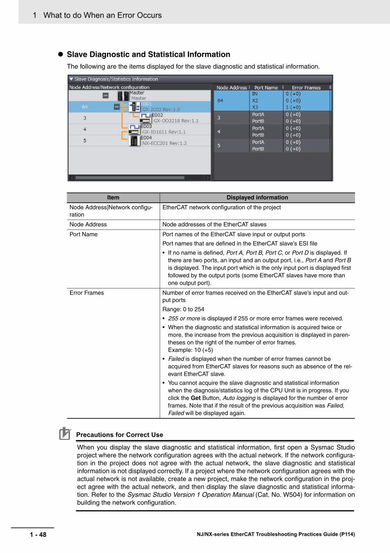
1 What to do When an Error Occurs
Slave Diagnostic and Statistical InformationThe following are the items displayed for the slave diagnostic and statistical information.
Precautions for Correct Use
When you display the slave diagnostic and statistical information, first open a Sysmac Studio project where the network configuration agrees with the actual network. If the network configura-tion in the project does not agree with the actual network, the slave diagnostic and statistical information is not displayed correctly. If a project where the network configuration agrees with the actual network is not available, create a new project, make the network configuration in the proj-ect agree with the actual network, and then display the slave diagnostic and statistical informa-tion. Refer to the Sysmac Studio Version 1 Operation Manual (Cat. No. W504) for information on building the network configuration.
Item Displayed information
Node Address|Network configu-ration
EtherCAT network configuration of the project
Node Address Node addresses of the EtherCAT slaves
Port Name Port names of the EtherCAT slave input or output ports
Port names that are defined in the EtherCAT slave’s ESI file
• If no name is defined, Port A, Port B, Port C, or Port D is displayed. If there are two ports, an input and an output port, i.e., Port A and Port B is displayed. The input port which is the only input port is displayed first followed by the output ports (some EtherCAT slaves have more than one output port).
Error Frames Number of error frames received on the EtherCAT slave’s input and out-put ports
Range: 0 to 254
• 255 or more is displayed if 255 or more error frames were received.
• When the diagnostic and statistical information is acquired twice or more, the increase from the previous acquisition is displayed in paren-theses on the right of the number of error frames. Example: 10 (+5)
• Failed is displayed when the number of error frames cannot be acquired from EtherCAT slaves for reasons such as absence of the rel-evant EtherCAT slave.
• You cannot acquire the slave diagnostic and statistical information when the diagnosis/statistics log of the CPU Unit is in progress. If you click the Get Button, Auto logging is displayed for the number of error frames. Note that if the result of the previous acquisition was Failed, Failed will be displayed again.
1 - 48 NJ/NX-series EtherCAT Troubleshooting Practices Guide (P114)

1 What to do When an Error Occurs1-4 C
heckin
g E
rrors U
sing
the
Co
mm
un
ication
s Statu
s
1
1-4-8 D
iagnostic and S
tatistical Log Function of the C
PU
Unit
The periodic auto-acquisition of the diagnostic and statistical information is allowed for the following purposes during a test run or normal operation of equipment.
• Checking the EtherCAT network line quality for predictive monitoring and preventive maintenance
• Finding locations of errors when they occur
Version Information
• A CPU Unit with unit version 1.11 or later is required to use this function.
OverviewThis function acquires the diagnostic and statistical information that the EtherCAT master and slaves have. The information is acquired at the specified cycle and saved as a log file in an SD Memory Card that is mounted on the CPU Unit.
Use system-defined variables to set the execution command for this function and the cycle at which the diagnostic and statistical information is saved.
Precautions for Correct Use
• An SD Memory Card is required to use this function. Refer to the NJ-series CPU Unit Hard-ware User’s Manual (Cat. No. W500) or NX-series CPU Unit Hardware User’s Manual (Cat. No. W535) for the SD Memory Card models supported by the CPU Unit.
• When the diagnosis/statistics log is in progress, you cannot acquire or clear the slave diagnos-tic and statistical information from the diagnostic and statistical information display of the Sys-mac Studio. Try it again after the diagnosis/statistics log is completed.
• When the diagnosis/statistics log is in progress, the response time in message communica-tions with EtherCAT slaves may be extended.
Diagnostic and Statistical Information to AcquireThe following table shows the information to acquire and describes the information.
*1 Only for the EtherCAT slaves that are registered in the EtherCAT master network configuration information of the project.
Precautions for Correct Use
If this function is executed when the EtherCAT master network configuration information is in the following status, only the master diagnostic and statistical information is saved in a log file. The slave diagnostic and statistical information and system-defined variables are not saved.
• The network configuration information is cleared for the Clear All Memory operation.• No EtherCAT slave is registered in the network configuration information.
1-4-8 Diagnostic and Statistical Log Function of the CPU Unit
Information to acquire Description
Master diagnostic and statistical information
Same as the master diagnostic and statistical information displayed by the diagnostic and statistical information display of Sysmac Studio. Refer to Master Diagnostic and Statistical Information on page 1-45 for details.
Slave diagnostic and statistical
information*1Same as the number of error frames for the slave diagnostic and statisti-cal information displayed by the diagnostic and statistical information dis-play of Sysmac Studio. Refer to Slave Diagnostic and Statistical Information on page 1-48 for details.
1 - 49NJ/NX-series EtherCAT Troubleshooting Practices Guide (P114)

1 What to do When an Error Occurs
Setting Cycle to Save Diagnostic and Statistical Information in a Log FileYou can specify the cycle to save the acquired diagnostic and statistical information in a log file within the range from 30 seconds to 30 minutes in units of seconds. You can also specify the cycle so that the diagnostic and statistical information is saved only once into a log file when the execution of this function is completed.
Specifications of Log FileThe acquired diagnostic and statistical information is saved as a CSV log file in the SD Memory Card. You can save a maximum of 1,000 diagnostic and statistical data in a log file.
The file name, file type and save location of the log file saved in the SD Memory Card are given below.
Additional Information
The following available space is required in an SD Memory Card to save the diagnostic and sta-tistical information.
Size of a data = 273 bytes + 51 bytes × Number of EtherCAT slaves
If the number of EtherCAT slaves is 512 and you want to save 1,000 diagnostic and statistical data, an available space of approximately 26 MB is required.
The specification of data saved in a log file is given below.
• For the first row, data are output in the following order: the CPU Unit model, software version, package version, hardware version, and serial ID. For the following rows, the date and time of acquisition and the diagnostic and statistical data are output.
• The number of error frames for the slave diagnostic and statistical information is left blank if the number of error frames cannot be acquired from the relevant EtherCAT slave.
Additional Information
The items of information such as the master diagnostic and statistical information output to a CSV file by this function are arranged in the same order as the diagnostic and statistical informa-tion display of Sysmac Studio. You can make the same file format by exchanging the places of the row and column of each item.
Related System-defined VariablesThe following system-defined variables are used to control execution of the diagnosis/statistics log. Refer to the NJ/NX-series CPU Unit Built-in EtherCAT Port User’s Manual (Cat. No. W505) for details on system-defined variables.
Item Specifications
File name ECAT_STATISTICS.csv
File format CSV
Save location Root folder
Variable name Meaning
_EC_StatisticsLogEnable Diagnosis/Statistics Log Enable
_EC_StatisticsLogCycleSec Diagnosis/Statistics Log Cycle
_EC_StatisticsLogBusy Diagnosis/Statistics Log Busy
_EC_StatisticsLogErr Diagnosis/Statistics Log Error
1 - 50 NJ/NX-series EtherCAT Troubleshooting Practices Guide (P114)

1 What to do When an Error Occurs1-4 C
heckin
g E
rrors U
sing
the
Co
mm
un
ication
s Statu
s
1
1-4-8 D
iagnostic and S
tatistical Log Function of the C
PU
Unit
ProceduresThe procedure to use the diagnosis/statistics log is as follows.
1 Set a value for _EC_StatisticsLogCycleSec (Diagnosis/Statistics Log Cycle).
The cycle to save the diagnostic and statistical information in a log file is set.
Set the value in units of seconds. (Example: set 30 for 30 seconds, set 1,800 for 30 minutes).
If 0 is set, the diagnostic and statistical information is saved only once when execution of this function is completed.
2 Change _EC_StatisticsLogEnable (Diagnosis/Statistics Log Enable) from FALSE to TRUE.
The execution of the diagnosis/statistics log is started.
• _EC_StatisticsLogErr (Diagnosis/Statistics Log Error) changes to FALSE.
• _EC_StatisticsLogBusy (Diagnosis/Statistics Log Busy) changes to TRUE.
During execution of the diagnosis/statistics log, the diagnostic and statistical information is acquired and saved in a log file at the cycle specified in step 1.
If one of the following (1) to (6) is detected during the diagnosis/statistics log, the diagnosis/sta-tistics log is automatically terminated.
(1) The maximum number of diagnostic and statistical data are saved in a log file.
(2) The SD Memory Card does not have sufficient available space.
(3) The SD Memory Card is write protected.
(4) There is no SD Memory Card.
(5) A synchronization (or downloading) is executed on the Sysmac Studio.
(6) The value set for _EC_StatisticsLogCycleSec is out of range.
• An EtherCAT Diagnosis/Statistics Log Started error is recorded in the event log.
• _EC_StatisticsLogBusy changes to FALSE.
• If (2), (3), (4) or (6) occurs, _EC_StatisticsLogErr changes to TRUE.
• An EtherCAT Diagnosis/Statistics Log Ended error is recorded in the event log.
3 Change _EC_StatisticsLogEnable (Diagnosis/Statistics Log Enable) from TRUE to FALSE.
Execution of the diagnosis/statistics log is terminated. The diagnostic and statistical information is saved in a log file when this variable changes to FALSE, regardless of the write cycle setting.
• _EC_StatisticsLogBusy changes to FALSE.
• An EtherCAT Diagnosis/Statistics Log Ended error is recorded in the event log.
1 - 51NJ/NX-series EtherCAT Troubleshooting Practices Guide (P114)

1 What to do When an Error Occurs
The following figure shows the timing chart.
Precautions for Correct Use
• When the diagnostic and statistical log function is started, the log file saved in the SD Memory Card is deleted and a new log file is created. If you want to retain the log file saved in the SD Memory Card, change the name of the log file or save the log file to a different memory device before starting the diagnostic and statistical log file function.
• During the diagnosis/statistics log, you cannot re-execute the diagnosis/statistics log. Check that _EC_StatisticsLogBusy is FALSE before you execute the diagnosis/statistics log.
• Even if you change the value of _EC_StatisticsLogCycleSec during the diagnosis/statistics log, the change is not reflected to the saving cycle of the diagnostic and statistical information. The changed saving cycle is used during the next execution of the diagnosis/statistics log. To use the changed saving cycle, you need to terminate the diagnosis/statistics log that is cur-rently executed.
• Access _EC_StatisticsLogErr after _EC_StatisticsLogBusy changes from TRUE to FALSE. The value of _EC_StatisticsLogErr varies while _EC_StatisticsLogBusy is TRUE.
Additional Information
The steps for retaining a log file previously saved in the SD Memory Card when newly execut-ing the diagnostic and statistical log function are indicated.
• Use the SD Memory Card instruction such as FileRename or FileCopy to change the file name.
• Use the FTP server function for the built-in EtherNet/IP to take the log file out.
• Eject the SD Memory Card and save the file in another medium.
Log file
Event logs
_EC_StatisticsLogErr
_EC_StatisticsLogEnable
_EC_StatisticsLogBusy
_EC_StatisticsLogCycle
EtherCAT Diagnosis/Statistics Log Started
EtherCAT Diagnosis/Statistics Log Ended
Write Cycle = 30
Write Cycle= 30
Write Cycle= 30
Write Cycle= 30
Acquired diagnostic/statistical information is saved in a log file.The previous log file
is deleted and a new file is created.
TRUE
FALSE
TRUE
FALSE
TRUE
FALSE
1 - 52 NJ/NX-series EtherCAT Troubleshooting Practices Guide (P114)

1 What to do When an Error Occurs1-5 M
on
itorin
g S
pecific E
rrors
1
1-5-1 C
hecking for Errors w
ith System
-defined Variab
les
1-5 Monitoring Specific Errors
Each error state is stored in an Error Status variable in the system-defined variables.
By monitoring Error Status variables in specific system-defined variables, you can check for the occur-rence of specific errors.
You can monitor an Error Status Variable in the system-defined variables to check EtherCAT master and slave statuses and errors that have occurred.
Structure of System-defined Variables
The system-defined variables include an Error Status variable, which shows the error status in a hierarchical structure. The system determines the error status of each level by logically ORing the error status information of the next lower level.
You can read the Error Status variable from an external device through communications.
System-defined variables for EtherCAT communication are described below.
Refer to the NJ/NX-series CPU Unit Software User’s Manual (Cat. No. W501) for information on system-defined variables.
1-5-1 Checking for Errors with System-defined Variables
Level 1 Level 2 Level 3 Level 4
_ErrSta Error Status variable (for the entire Controller)
_EC_ErrSta
_EC_PortErr
_EC_MstrErr
_EC_SlavErr
_EC_SlavErrTbl
Error status variable for EtherCAT Master Function Module
Error status variable for communications ports
Error status variable for master
Summary error status variable for all slaves
Error status variable for slaves
1 - 53NJ/NX-series EtherCAT Troubleshooting Practices Guide (P114)

1 What to do When an Error Occurs
How to Monitor System-defined Variables Using the Sysmac Studio
In addition to using a user program, you can monitor system-defined variables from the Sysmac Stu-dio using the methods below.
• Monitoring
You can use the monitoring function to monitor ON/OFF states of contacts and coils, and current values of variables.
You can register any system-defined variables in the monitoring watch window to monitor only those variables.
For information on monitoring, refer to the Sysmac Studio Version 1 Operation Manual (Cat. No. W504).
• Data trace
This function lets you sample specified variables without the need for a program. You can select from two types: trigger trace and continuous trace. Use trigger trace to set a trigger condition and record the data at the time that the trigger condition is met. Use continuous trace to continuously execute sampling without a trigger and record the results in a computer file.
By specifying system-defined variables to be sampled, you can trace the occurrence/reset states of specific errors.
For information on data trace, refer to the Sysmac Studio Version 1 Operation Manual (Cat. No. W504).
System-defined variables for EtherCAT communication
For details on system-defined variables related to EtherCAT communication errors, refer to the NJ/NX-series CPU Unit Built-in EtherCAT Port User’s Manual (Cat. No. W505)
1 - 54 NJ/NX-series EtherCAT Troubleshooting Practices Guide (P114)

1 What to do When an Error Occurs1-6 S
aving
the C
om
mu
nic
ation
s S
tatu
s (Fo
r Inq
uiry to
OM
RO
N)
1
1-6 Saving the Communications Status (For Inquiry to OMRON)
Packet monitoring stores a certain number of the most recent packets sent and received by the Ether-CAT master along with time information.You can use an EtherCAT communications instruction or the Sysmac Studio to save the captured packet data in packet data files in the system in the CPU Unit.
You can use any of the following methods to obtain the packet data saved in the system memory in the CPU Unit.
• Reading directly from the Sysmac Studio
• Saving to an SD Memory Card inserted in the CPU Unit
You can view the captured packet data with packet analyzer software, such as WireShark. You can also use the data for analysis applications, such as error analysis and data mining.
Additional Information
For the NJ301- and NJ101- CPU Units, unit version 1.10 or later and Sysmac Studio version 1.12 or higher are required to use the packet monitoring function.
The _EC_PktMonStop system-defined variable, which shows the operating status of packet monitoring, will always be TRUE in an NJ301- CPU Unit with unit version 1.09 or earlier.
If you execute any EtherCAT instructions for packet monitoring (EC_StartMon, EC_StopMon, EC_SaveMon, or EC_CopyMon) in the user program, an error is returned that says packet mon-itoring cannot be used.
NJ/NX-series CPU Unit
Sysmac Studio
You can check and analyze data with packet analyzer software, such as WireShark.
You can save packet data to the memory in the CPU Unit.
You can save data to files on an SD Memory Card.
Packet data
SD Memory Card
Packets
Reading directly from the Sysmac Studio
Slave Slave
1 - 55NJ/NX-series EtherCAT Troubleshooting Practices Guide (P114)

1 What to do When an Error Occurs
You can start and stop packet monitoring either with instructions in the user program or with operations on the Sysmac Studio.
Using Instructions in the User Program• EC_StartMon (Start EtherCAT Packet Monitor) instruction: Starts the execution of packet monitor-
ing and continues to update a fixed number of packets.
• EC_StopMon (Stop EtherCAT Packet Monitor) instruction: Stops the execution of packet monitor-ing.
Operation from the Sysmac Studio
1 Start the Sysmac Studio and go online with the Controller.
2 Double-click EtherCAT under Configurations and Setups in the Multiview Explorer. Or, right-click EtherCAT under Configurations and Setups and select Edit.
3 Right-click in the EtherCAT Network Configuration Tab Page and select Display Packet Moni-tor from the menu.
The Packet Monitor Dialog Box is displayed.
Starting and Stopping Packet Monitor
1 - 56 NJ/NX-series EtherCAT Troubleshooting Practices Guide (P114)

1 What to do When an Error Occurs1-6 S
aving
the C
om
mu
nic
ation
s S
tatu
s (Fo
r Inq
uiry to
OM
RO
N)
1
4 Click the Start Button to begin monitoring packets.
5 Click the Stop Button to stop monitoring packets.
Reading Data from the Sysmac StudioAfter you stop packet monitoring, you can use the Sysmac Studio to read the packet data and save it in a file.
1 Stop monitoring packets.
2 Click the Save Packet Data Button to save the packet data.
The Save Dialog Box is displayed.
3 Input a file name, and then click the Save Button.
A TCPDump packet data file with a .cap extension is saved.
Saving to an SD Memory Card from Memory in the CPU UnitStop monitoring packets, and then execute the EC_SaveMon (Save EtherCAT Packets) instruction to save a given quantity of collected packet data in memory in the CPU Unit. Then, execute the EC_-CopyMon (Transfer EtherCAT Packets) instruction to save the packet data that was saved in the CPU Unit to a file on an SD Memory Card inserted into the CPU Unit. You can specify the name of the file that is saved in the SD Memory Card. The number of files is limited only by the space that is available on the SD Memory Card.
Additional Information
• Packet data in the CPU Unit’s memory is not retained when the power is interrupted.
• Packet data cannot be saved while packets are being monitored.
• Packet monitoring cannot be started while saving packet data.
• If an SD Memory Card is not inserted and you execute the instruction to copy the data to the SD Memory Card, then an error is returned. If there is no SD Memory Card, only the one file in the CPU Unit’s memory can be read to the Sysmac Studio.
• Packet monitoring starts when the power is turned ON.
Saving Packet Data
1 - 57NJ/NX-series EtherCAT Troubleshooting Practices Guide (P114)

1 What to do When an Error Occurs
Packet Monitoring Specifications
Item Specification
Maximum data size of one packet data file 12 MB
Maximum number of packets that can be obtained 3,904 packets
Format of packet data file TCPDump format (cap)
Time information Recorded (unit: s) The elapsed time starting when packet monitoring begins is recorded. (Packet moni-toring can be started when power turns ON, for an EtherCAT instruction, or for a Sysmac Studio opera-tion.)
Save location for packet data file CPU Unit’s system: 1 file SD Memory Card inserted in CPU Unit: Multiple files (up to capacity of SD Memory Card)
1 - 58 NJ/NX-series EtherCAT Troubleshooting Practices Guide (P114)

1 What to do When an Error Occurs1-6 S
aving
the C
om
mu
nic
ation
s S
tatu
s (Fo
r Inq
uiry to
OM
RO
N)
1
This sample transfers EtherCAT communications packets to an SD Memory Card when an EtherCAT slave error occurs. The file name is ‘PacketFile.’ The processing procedure is as follows:
1 The system-defined variable _EC_ErrSta (EtherCAT Error) is monitored and processing is started if an error occurs.
2 The EC_StopMon instruction is used to stop execution of packet monitoring for EtherCAT com-
munications.
3 The EC_SaveMon instruction is used to save EtherCAT communications packet data to a file in
the system of the CPU Unit.
4 The EC_CopyMon instruction is used to copy that file to the SD Memory Card.
5 The EC_StartMon instruction is used to restart execution of packet monitoring for EtherCAT
communications.
Sample Programming
1 - 59NJ/NX-series EtherCAT Troubleshooting Practices Guide (P114)

1 What to do When an Error Occurs
LD
Processing completedExecution condition
Variable Data type Initial value Comment
OperatingEndOperatingABCRS_instanceEC_StopMon_instanceEC_SaveMon_instanceEC_CopyMon_instanceEC_StartMon_instance
FalseFalseFalseFalseFalse
BOOLBOOLBOOLBOOLBOOLRSEC_StopMonEC_SaveMonEC_CopyMonEC_StartMon
EC_StartMon_instance.Done
EC_StopMon_instance.Error
_EC_PktMonStop
Determine if instruction execution is completed.
Monitor for EtherCAT errors.
OperatingEnd
Operating
OperatingEnd
_EC_ErrStaWORD#16#00
EC_SaveMon_instance.Error
EC_CopyMon_instance.Error
EC_StartMon_instance.Error
A
B
RS Set Q1 Reset1
RS_instance
<>ENIn1In2
UpIn
EC_StopMon_instance.Busy
A EC_SaveMon_instance.Busy EC_CopyMon_instance.Busy
B _EC_PktSaving
EC_StartMon_instance.Busy
_EC_ErrSta_EC_PktMonStop_EC_PktSaving_Card1Ready
WORDBOOLBOOLBOOL
Constant
Internal Variables
External Variables Variable Data type Comment
Built-in EtherCAT ErrorPacket Monitoring StoppedSaving Packet Data FileSD Memory Card Enabled Flag
1 - 60 NJ/NX-series EtherCAT Troubleshooting Practices Guide (P114)

1 What to do When an Error Occurs1-6 S
aving
the C
om
mu
nic
ation
s S
tatu
s (Fo
r Inq
uiry to
OM
RO
N)
1
Inline STProcessing after normal end
Instruction execution
C
Operating1 // Processing after normal end2 ;
Operating
C
EC_StopMonExecute
EC_StopMon_instanceEC_SaveMon
Execute
EC_SaveMon_instance
EC_StartMon
Execute
EC_StartMon_instance
DoneBusyError
ErrorID
DoneBusyError
ErrorID
‘PacketFile’
EC_CopyMon
ExecuteFileName
EC_CopyMon_instance
DoneBusyError
ErrorID
DoneBusyError
ErrorID
_Card1Ready
1 - 61NJ/NX-series EtherCAT Troubleshooting Practices Guide (P114)

1 What to do When an Error Occurs
ST
Controller error in the EtherCAT Master Function Module.Detect when EC_Err changes to TRUE.ProcessingStage change
Variable Data type Initial value Comment
EC_Err:=(_EC_ErrSta <> WORD#16#00);R_TRIG_instance(Clk:=EC_Err, Q=>EC_Err_Trigger);
IF ( (EC_Err_Trigger=TRUE) AND (DoEC_PktSave=FALSE) AND (_EC_PktMonStop=FALSE) AND (_EC_PktSaving=FALSE) AND (_Card1Ready=TRUE) ) THEN DoEC_PktSave:=TRUE; Stage :=INT#1; EC_StopMon_instance(Execute:=FALSE); EC_SaveMon_instance(Execute:=FALSE); EC_CopyMon_instance(Execute:=FALSE); EC_StartMon_instance(Execute:=FALSE);END_IF;
IF (DoEC_PktSave=TRUE) THEN CASE Stage OF 1 : EC_StopMon_instance( Execute :=TRUE);
IF (EC_StopMon_instance.Done=TRUE) THEN Stage:=INT#2; ELSIF (EC_StopMon_instance.Error=TRUE) THEN Stage:=INT#10; END_IF;
2 : EC_SaveMon_instance( Execute :=TRUE);
IF (EC_SaveMon_instance.Done=TRUE) THEN Stage:=INT#3; ELSIF (EC_SaveMon_instance.Error=TRUE) THEN Stage:=INT#20; END_IF;
3 : EC_CopyMon_instance( Execute :=TRUE, FileName:=’PacketFile’);
IF (EC_CopyMon_instance.Done=TRUE) THEN Stage:=INT#4; ELSIF (EC_CopyMon_instance.Error=TRUE) THEN Stage:=INT#30; END_IF;
// Start sequence when _EC_ErrSta changes to TRUE.
// Instruction execution
// Stop EtherCAT packet monitor.
// Save EtherCAT packet data to file in system.
// Copy EtherCAT packet data file to the SD Memory Card.
// Normal end
// Error end
// Normal end
// Error end
// Normal end
// Error end
// Initialize instance.
EC_ErrEC_Err_TriggerDoEC_PktSaveStageR_TRIG_instanceEC_StopMon_instanceEC_SaveMon_instanceEC_CopyMon_instanceEC_StartMon_instance
FalseFalseFalse0
BOOLBOOLBOOLINTR_TRIGEC_StopMonEC_SaveMonEC_CopyMonEC_StartMon
_EC_ErrSta_EC_PktMonStop_EC_PktSaving_Card1Ready
WORDBOOLBOOLBOOL
Constant
Internal Variables
External Variables Variable Data type Comment
Built-in EtherCAT ErrorPacket Monitoring StoppedSaving Packet Data FileSD Memory Card Enabled Flag
1 - 62 NJ/NX-series EtherCAT Troubleshooting Practices Guide (P114)

1 What to do When an Error Occurs1-6 S
aving
the C
om
mu
nic
ation
s S
tatu
s (Fo
r Inq
uiry to
OM
RO
N)
1
4 : EC_StartMon_instance( Execute :=TRUE);
IF (EC_StartMon_instance.Done=TRUE) THEN Stage:=INT#0; ELSIF (EC_StartMon_instance.Error=TRUE) THEN Stage:=INT#40; END_IF;
0 : DoEC_PktSave:=FALSE;
ELSE DoEC_PktSave:=FALSE; END_CASE;END_IF:
// Processing after normal end
// Processing after error end
// Restart EtherCAT packet monitoring.
// Normal end
// Error end
1 - 63NJ/NX-series EtherCAT Troubleshooting Practices Guide (P114)

1 What to do When an Error Occurs
1-7 Error (Event) List
For details on the list of errors (events) that may occur on the EtherCAT master unit, refer to the NJ/NX-series CPU Unit Built-in EtherCAT Port User's Manual (Cat. No. W505).
For details on the list of errors (events) that may occur on the EtherCAT slave unit, refer to the NX-series EtherCAT Coupler Unit User's Manual (Cat. No. W519).
1-7-1 EtherCAT Master
1-7-2 EtherCAT Slave
1 - 64 NJ/NX-series EtherCAT Troubleshooting Practices Guide (P114)

2
This section describes the actions to take for frequently encountered problems.
2-1 Process Data Reception Timeout Error . . . . . . . . . . . . . . . . . . . . . . . . . . . . 2-22-1-1 Process Data Reception Timeout Error . . . . . . . . . . . . . . . . . . . . . . . . . . . . . 2-2
2-1-2 General Flow of Troubleshooting . . . . . . . . . . . . . . . . . . . . . . . . . . . . . . . . . . 2-3
2-1-3 Collecting Information for Troubleshooting . . . . . . . . . . . . . . . . . . . . . . . . . . . 2-3
2-1-4 Identifying the Cause . . . . . . . . . . . . . . . . . . . . . . . . . . . . . . . . . . . . . . . . . . . 2-4
2-1-5 Checking the Cause . . . . . . . . . . . . . . . . . . . . . . . . . . . . . . . . . . . . . . . . . . . . 2-6
2-2 Slave Initialization Error . . . . . . . . . . . . . . . . . . . . . . . . . . . . . . . . . . . . . . . . 2-92-2-1 Slave Initialization Error . . . . . . . . . . . . . . . . . . . . . . . . . . . . . . . . . . . . . . . . . 2-9
2-2-2 General Flow of Troubleshooting . . . . . . . . . . . . . . . . . . . . . . . . . . . . . . . . . 2-10
2-2-3 Check for a Major Fault Level Controller Error . . . . . . . . . . . . . . . . . . . . . . . .2-11
2-2-4 Checking for Network Changes . . . . . . . . . . . . . . . . . . . . . . . . . . . . . . . . . . .2-11
2-2-5 Checking the Source of a Slave Initialization Error . . . . . . . . . . . . . . . . . . . 2-12
2-3 Troubleshooting for Identifying the Cause . . . . . . . . . . . . . . . . . . . . . . . . 2-13
Example Actions for Frequently Encountered Problems
2 - 1NJ/NX-series EtherCAT Troubleshooting Practices Guide (P114)

2 Example Actions for Frequently Encountered Problems
2-1 Process Data Reception Timeout Error
This section describes what to do when a Process Data Reception Timeout error occurs.
The Controller (EtherCAT master) performs process data communication each period. When process
data is repeatedly not received within the communication period a set number of times*1 or more, a Pro-cess Data Reception Timeout error occurs.
*1. The default setting for the number of times for detection of a Process Data Reception Timeout error is 2. This can be set from the Sysmac Studio.
2-1-1 Process Data Reception Timeout Error
Controller (EtherCAT master)
Execute process data
communication each period
Slave
Process data does not return to the controller (communication master) due to a cable wire break, etc.
When process data is not received within the communication period repeatedly, a process data reception timeout is detected
2 - 2 NJ/NX-series EtherCAT Troubleshooting Practices Guide (P114)

2 Example Actions for Frequently Encountered Problems2-1 P
roce
ss Data R
eceptio
n T
imeo
ut E
rror
2
2-1-2 General F
low of T
roubleshooting
Follow the flow below to troubleshoot a process data reception timeout.
1 Collect information for troubleshooting
When a Process Data Reception Timeout error occurs, other errors may occur at or near the same time. Collecting and combining information on these errors may facilitate the troubleshoot-ing process.
Error information can be found in the Sysmac Studio event log.
2-1-3 Collecting Information for Troubleshooting on page 2-3
2 Identifying the cause
There is a high likelihood that a Process Data Reception Timeout error is caused by a problem on the EtherCAT line. Use statistical information to pinpoint the location of the problem and identify the cause.
Check the diagnostic and statistical information of the Sysmac Studio.
2-1-4 Identifying the Cause on page 2-4
3 Check the specific cause
Check if the cause identified in steps 1 and 2 is actually causing the error.
When a Process Data Reception Timeout occurs, the cause is often a problem on the EtherCAT line. A problem on the EtherCAT line may also cause other errors at or near the same time as the Process Data Reception Timeout error occurs. For this reason, collecting detailed information on other errors that occurred near the time of the process data reception timeout can help identify the cause.
Follow the steps below to collect information to troubleshoot the problem.
1 Start the Sysmac Studio and go online.
2 Open Tools - Troubleshooting.
3 Select the Controller Event Log Tab.
In the controller event log, check errors that occurred near the time of the process data recep-tion timeout and the detailed information on the errors.
2-1-2 General Flow of Troubleshooting
2-1-3 Collecting Information for Troubleshooting
2 - 3NJ/NX-series EtherCAT Troubleshooting Practices Guide (P114)

2 Example Actions for Frequently Encountered Problems
If you cannot identify the cause of the error from the event log alone, use the Sysmac Studio statistical information.
When you suspect that the cause of the problem lies on the EtherCAT line, follow the flow below to identify the cause.
1 Determine whether the cause of the problem lies on the EtherCAT line
Ascertain the state of master communication from trends in the master diagnostics and statisti-cal information, and determine whether a problem exists.
2 Identify the likely location of the problem on the EtherCAT line
Identify the likely location of the problem from trends in the slave diagnostics and statistical information.
3 Identify the cause
Check the equipment used and installation/layout conditions, and identify the cause of the prob-lem in that location.
Ascertain the state of master communication by looking at the frame reception timeout count, number of discarded process data receptions, number of discarded message receptions, and number of CRC error frames received.
Even when the network is normal, it is not unusual to observe several occurrences of these values over several days. As such, it cannot be concluded that there is a problem from several occurrences of the values.
If one of the items occurs several tens of times and the value increases frequently, it can be inferred that there is a problem.
The master diagnostic and statistical information is cleared when the Controller power is interrupted or the clear button is pressed.
Follow the steps below to determine whether there is a problem on the EtherCAT line.
1 Acquire the master diagnosis/statistics information in the Sysmac Studio.
Refer to 1-4-7 Diagnostic and Statistical Information Display of Sysmac Studio on page 1-42.
2 Check the updated master diagnostic and statistical information.
Check if the frame reception timeout count, number of discarded process data receptions, num-ber of discarded message receptions, and number of CRC error frames received are increasing over time.
• Not increasing:
A problem does not exist on the EtherCAT line.
• Increasing:
A problem exists on the EtherCAT line. Identify the likely location of the problem from the slave diagnostic and statistical information.
2-1-4 Identifying the Cause
General Flow of Identifying the Cause
Determining Whether a Problem Exists on the EtherCAT Line
2 - 4 NJ/NX-series EtherCAT Troubleshooting Practices Guide (P114)

2 Example Actions for Frequently Encountered Problems2-1 P
roce
ss Data R
eceptio
n T
imeo
ut E
rror
2
2-1-4 Identifying the Ca
use
Identify the likely location of the problem by looking at the number of Error Frames in the slave diagnos-tic and statistical information. If one slave has a large number of Error Frames, it can be inferred that there is a problem in the slave, in the upstream slave, in a cable, or in a connector. If there is a large number of error frame receptions in multiple locations, a problem in one location may be affecting other locations, or multiple locations may have problems. Each location must be checked.
When the power to a slave is interrupted, the slave's diagnosis and statistical information is cleared.
Follow the steps below to identify the likely location of a problem on the EtherCAT line.
1 Acquire the master diagnosis/statistics information in the Sysmac Studio.
Refer to 1-4-7 Diagnostic and Statistical Information Display of Sysmac Studio on page 1-42.
2 Check the number of Error Frames in the slave diagnostic and statistical information.
(1) When one slave has a large number of Error Frames
It can be inferred that the problem lies in that slave, in the upstream slave, in the cable that connects the two, or in a connector.
(2) When multiple slaves have a large number of error frame receptions
1) Identify the most upstream slave that has a large number of error frame receptions.
2) Remove that slave from the network, click the Update Button on the Slave Diagno-
sis/Statistics Information Tab, and view the changes in the number of Error Frames.
3) If there are no increases in the number of Error Frames, it can be inferred that the
problem lies in that slave, in the upstream slave, in the cable that connects the two, or
in a connector. Identify the cause.
When Slave Diagnostic and Statistical Information Cannot be Obtained
If a slave has failed on the network, it is possible that EtherCAT communication will fail and slave diagnostic and statistical information cannot be obtained.
To resume EtherCAT communication and obtain slave diagnostic and statistical information, the failed slave must be identified and removed from the EtherCAT network.
Follow the steps below to find and remove the failed slave.
1 Disconnect the cable from any slave on the EtherCAT network.
There is no criterion for deciding which slave to disconnect. If there are slaves for which you have previously acquired slave diagnostic and statistical information, you may find it effective to select a slave with a large number of error frame receptions, or you may find it effective to select the slave using a binary search.
2 Reset the error.
3 Acquire the slave diagnostic and statistical information.
4 If you cannot acquire the information, disconnect another cable and repeat steps 1 to 3.
Procedure for Identifying the Likely Location of a Problem on the EtherCAT Line
For the procedure for identifying the likely location of a problem on the EtherCAT line, refer to 1-4-4 Identifying the Cause of the Error on page 1-37.
Identifying the Location of the Problem on the EtherCAT Line
2 - 5NJ/NX-series EtherCAT Troubleshooting Practices Guide (P114)

2 Example Actions for Frequently Encountered Problems
When you have identified the likely location of a problem, check the following items in the order listed to identify the cause.
2-1-5 Checking the Cause
No. Item to Check Method
1. Check the slaves, the Ethernet cable that connects the slaves, and the connectors.
1-1 Cable and connectors correctly connected?
Disconnect and then reconnect the cable.
1-2 Broken wires in the cable? Use a cable checker to check for broken wires. Check for con-nector and pin damage.
1-3 Correct cable connections? Refer to Cautions for Cable Connections on page 2-7 below to check the connections (cable pairs).
1-4 Are you using the recommended cable?
Make sure the cable is Category 5 or higher and is STP twisted pair. Noise may affect a non-recommended cable. Change to the recommended cable.
1-5 Slave failure? Replace the slave and check for changes in operation.
2. Check the installation conditions
2-1 Is the input voltage suitable? Use a tester to check if a suitable voltage is being input into the slave.
2-2 Any power lines nearby? Noise may be affecting operation. Refer to Examples of Investi-gating Cable Noise in the Installation Environment on page 2-8 below to check for noise.
2-3 Properly grounded?
2-4 Cable too long?
3. Check the devices used and the installation conditions
3-1 Relay connector The shielding effect may have compromised and noise may be affecting operation. Refer to Examples of Investigating Cable Noise in the Installation Environment on page 2-8 below to check for noise.
3-2 Turntable Vibration may cause a contact failure between the cable and con-nector.
3-3 Slip ring A cable contact failure may have occurred.
3-4 General purpose Ethernet hub A general purpose Ethernet hub may not allow correct frame transmission and reception.
2 - 6 NJ/NX-series EtherCAT Troubleshooting Practices Guide (P114)

2 Example Actions for Frequently Encountered Problems2-1 P
roce
ss Data R
eceptio
n T
imeo
ut E
rror
2
2-1-5 Checking the C
ause
When using 8-conductor LAN cable, either the T568A wiring or the T568B wiring below is required.
Cautionary points are as follows.
• Take care that pins 3 and 6 are paired, and pins 4 and 5 are paired.
• Frequent communication errors have been reported when pins 1 and 2, pins 3 and 4, pins 5 and 6, and pins 7 and 8 are paired (wired with the same pair number). In this case, although there is electri-cal conductivity when both ends of the cable are wired in the same way, the signals that were origi-nally supposed to be paired are not, and this leads to communication errors.
• Wiring diagrams for the T568A and T568B standards are shown below.
T568A RJ45 Wiring Diagram
T568B RJ45 Wiring Diagram
Cautions for Cable Connections
Pin No. Pair No. Wire Type Wire Color Pin Position
1 3 tip
White/orange striped
2 3 ring
Orange solid
3 2 tip
White/green striped
4 1 ring
Blue solid
5 1 tip
White/blue striped
6 2 ring
Green solid
7 4 tip
White/brown striped
8 4 ring
Brown solid
Pin No. Pair No. Wire Type Wire Color Pin Position
1 2 tip
White/green striped
2 2 ring
Green solid
3 3 tip
White/orange striped
4 1 ring
Blue solid
5 1 tip
White/blue striped
6 3 ring
Orange solid
7 4 tip
White/brown striped
8 4 ring
Brown solid
2 - 7NJ/NX-series EtherCAT Troubleshooting Practices Guide (P114)

2 Example Actions for Frequently Encountered Problems
Check potential differences on the FG line at the following times.
• During normal operation
• During the interval from power-on to completion of startup
Potential changes normally occur during these two times. Check the specific timing of the changes (example: servo ON, main circuit ON).
• Either install the Controller a minimum of 200 mm away from any high-voltage line or power line that is nearby, or run the high-voltage line or power line through a metal tubing and completely ground the metal tubing (ground resistance of 100 Ω or less).
• AC power input waveform of Controller power (AC)
• Potential difference between FG of Controller power and FG of control panel on which the Controller is mounted
• Potential difference between FG of any slave and FG of control panel
• Potential difference between FG of Controller power and FG of the above slave
• Measure (with a current probe) the current that flows to FG of the Controller power (if you do not have a current probe, you can insert a 1Ω resistance in the FG line and measure the voltage across this resistance as a substitute for measuring the current)
• Waveform of 24 VDC power for EtherCAT slave (between 0 and 24 V)
(a) If this 24 VDC power supply supplies power to all slaves, check the potential (does a drop occur?) and waveform of the 24 V supplied to the slave farthest from the Controller.
(b) If this 24 VDC power supply is also used for I/O (relays, etc.), it must be monitored for abnormal waveforms.
When there is a coupler
• Potential difference between FG of coupler and FG of control panel
• Potential difference between FG of coupler and FG of the above slave
• Measure the current flowing to FG of the coupler (with a current probe)
Examples of Investigating Cable Noise in the Installation Environ-ment
Example: Separating Controller from Power Lines
Metal tubing
200 mm
200 mm
High-voltage power panelPower lines
Powerlines
Ground to 100 Ω or lessController Controller
2 - 8 NJ/NX-series EtherCAT Troubleshooting Practices Guide (P114)

2 Example Actions for Frequently Encountered Problems2-2
Slave In
itialization
Erro
r
2
2-2-1 Slave Initialization E
rror
2-2 Slave Initialization Error
This describes explains what to do when a Slave Initialization Error occurs.
EtherCAT communication provides four control states. Communication is controlled by switching between these states.
The EtherCAT master controls the switching of the communication control states of EtherCAT slaves. A Slave Initialization Error occurs when the EtherCAT master detects that an EtherCAT slave was unable to change states.
2-2-1 Slave Initialization Error
Init
Operational
Pre-Operational
Safe-Operational
Power ON A slave initialization error occurs when an EtherCAT slave cannot change states
Switching of communication control states of EtherCAT slaves
2 - 9NJ/NX-series EtherCAT Troubleshooting Practices Guide (P114)

2 Example Actions for Frequently Encountered Problems
Follow the flow below to troubleshoot a Slave Initialization Error.
1 Troubleshoot problems that should be corrected in advance
• If the Slave Initialization Error occurs due to the effects of another problem, troubleshoot the other problem rather than the Slave Initialization Error.
• Check for problems that have occurred, and troubleshoot problems that must be corrected in advance.
2 Identify the cause of the slave initialization error
• Check possible causes in order of likelihood, and identify the cause.
• Causes inferred depend on the source and symptoms of the problem, and as such the order of identifying the cause will vary.
Follow the flow below to troubleshoot a Slave Initialization Error.
2-2-2 General Flow of Troubleshooting
Flow of Troubleshooting
Yes
Troubleshoot major fault level Controller error
Check for a major fault level Controller error
Check for network changes
Check source of slave initialization error
Identify cause inferred to lie on EtherCAT line
Identify cause inferred to lie on EtherCAT line
Identify cause inferred to be in slave
Identify cause inferred to lie on EtherCAT line
Identify cause inferred to be in slave
Check changesNo
No
Yes
Source is slave
1. Troubleshoot problems that must be corrected in advance
2. Identify the cause of the slave initialization error
Source is master
Occurs on multiple slavesWhen occurs, slave changes
Only occurs on specific slave
P. 2-11
P. 2-11
P. 2-12
P. 2-12 P. 2-12 P. 2-12
P. 2-12 P. 2-12
2 - 10 NJ/NX-series EtherCAT Troubleshooting Practices Guide (P114)
2 Example Actions for Frequently Encountered Problems2-2
Slave In
itialization
Erro
r
2
2-2-3 Check for a M
ajor Fault L
evel Controller E
rror
If a major fault level Controller error occurs, process data communication will stop. This may prevent the slave from switching states and thereby cause a Slave Initialization Error.
First troubleshoot the major fault level Controller error and remove the cause.
When you have removed the cause of the major fault level Controller error, reset the Controller error and verify that a Slave Initialization Error does not occur.
Follow the steps below to check for a major fault level Controller error.
1 Open the event log in the Sysmac Studio.
2 Check if a major fault level Controller error has occurred.
3 If a Slave Initialization Error occurs after you have troubleshooted the current problem, it can be inferred that another cause exists. Follow the flow in section 2-2-3 to troubleshoot again.
A Slave Initialization Error can be caused by configuration changes, resetting of errors, and other events in the processing that the EtherCAT master performs to recognize slaves on the EtherCAT net-work.
Collect information that will help troubleshooting, such as whether changes were made in the network configuration before the Slave Initialization Error occurred.
Collect the following information.
• Was a slave added, deleted, or replaced?
Was the power of an added slave turned ON?
• Was an NX Unit on the slave terminal added, deleted, or replaced?
If a PD Unit is included, is voltage supplied?
2-2-3 Check for a Major Fault Level Controller Error
2-2-4 Checking for Network Changes
2 - 11NJ/NX-series EtherCAT Troubleshooting Practices Guide (P114)

2 Example Actions for Frequently Encountered Problems
Possible causes of Slave Initialization Errors vary depending on the source. Check the source of the problem in the event log of the Controller.
• When the source is the slave
This indicates that there is no response to the master from the slave. It can be inferred that the cause lies on the EtherCAT line or in the slave.
• When the source is the master
This indicates that communication between the master and slave is not taking place normally. It can be inferred that the cause lies on the EtherCAT line.
(a) Identifying a cause that is inferred to lie on the EtherCAT line
A Slave Initialization Error whose source is the master indicates that communication between the master and slave is not taking place normally, and it can be inferred that the cause lies on the Eth-erCAT line.
A Slave Initialization Error whose source is the slave indicates that the response from the slave does not reach the master. If multiple slaves are the source or the source changes, it can be inferred that the cause lies on the EtherCAT line.
If it is inferred that the cause lies on the EtherCAT line, refer to 2-1-4 Identifying the Cause on page 2-4 to identify the cause.
(b) Identifying a cause that is inferred to be in the slave
Follow the steps below to identify and remove a cause that is inferred to lie in the slave. It is possi-ble that there are multiple causes, so repeat the steps until the problem no longer occurs.
1 Check the details of the error that occurs on the slave
Use the event log, status indicators, and other information as appropriate for the slave type to check the details of the error.
Refer to 1-2-1 CPU Unit Operating Status on page 1-6 for details.
2 Remove the cause on the slave
• Follow the appropriate troubleshooting procedure for the slave to identify and remove the cause.
• Reset the master/slave error.
For the procedure for removing the cause of an error that occurred on a slave, refer to 1-1-2 Resetting Errors on page 1-4.
2-2-5 Checking the Source of a Slave Initialization Error
2 - 12 NJ/NX-series EtherCAT Troubleshooting Practices Guide (P114)

2 Example Actions for Frequently Encountered Problems2-3 T
rou
blesh
oo
ting
for Id
entifyin
g th
e C
ause
2
2-3 Troubleshooting for Identifying the Cause
If you were unable to identify the cause using the procedures in the preceding sections, the details of the problem must be analyzed. OMRON will perform this analysis. Please provide the information below.
• Collect the information before turning OFF the system power, while the error is in effect.
• Depending on the state of the system, it may not be possible to obtain some information; however, please collect as much information as possible.
Desired information Purpose How to collect
Event log Check if any events occurred that may have led to the error.
Refer to the Sysmac Studio Version 1 Operation Manual (Cat. No. W504).
Current values of system variables
Check the status of the EtherCAT net-work on which the error has occurred. The status changes when you turn OFF the Controller or slave power. Collect the information before turning OFF the system power.
Check and record the current values of the following system variables on the Watch Tab Page.
_EC_EntrySlavTbl[1..192]: Network Connected Slave Table
_EC_MBXSlavTbl[1..192]: Message Communications Enabled Slave Table
_EC_PDSlavTbl[1..192]: Process Data Communicating Slave Table
_EC_PDActive: Process Data Commu-nicating Status
Diagnostic/statistical infor-mation
Check the quality of the master and slave lines When you turn OFF the power of the controller or slave, initial-ization takes place. Collect the informa-tion before turning OFF the system power.
Refer to 1-4 Checking Errors Using the Communications Status on page 1-33 for details.
Controller backup data Check the events that have occurred in the Controller internal log. The controller internal log is included in the Controller backup data.
System behavior can also be inferred from the configuration information, user programs, and the current values of retained variables.
Use the SD memory card backup func-tion.
Packet data Check the packet send/receive interval, send/receive order, and whether any invalid packets exist. Packets are erased when the Controller power is turned OFF. Collect the information before turning OFF the system power.
Refer to Saving Packet Data on page 1-57 for details.
Operation performed when the problem occurred
This may provide a clue for our analysis. Please indicate the steps for reproduc-tion of the problem, and the state of the system when the problem occurred.
Refer to Information That Will Acceler-ate Analysis on page 2-14 below.
2 - 13NJ/NX-series EtherCAT Troubleshooting Practices Guide (P114)

2 Example Actions for Frequently Encountered Problems
Information that you provide such as the system state and steps for reproduction of the problem will give useful clues and accelerate analysis.
The following types of information are useful.
Did you turn OFF the slave power or disconnect a cable?
• What steps did you follow to turn OFF the slave power or disconnect a cable?
• If you disconnected a cable, what steps did you follow?
a) Did you right-click slave in the EtherCAT Tab Page and select Disconnect/Connect Slave?
b) Did you disable the slave?
c) Did you turn OFF the slave power or disconnect a cable without following the steps in the Sys-mac Studio?
Did you execute any other functions at the same time?
• Did you reset the error?
Is this executed every cycle?
• Did you execute SDO message communication?
• Did you execute CIP communication?
What device were you communicating with?
Did you perform a task immediately before the error occurred?
• Did you add or replace a device?
• Did you correct the wiring?
Was there a change in the installation environment?
• Did a power outage or earthquake occur?
• Did an event occur that might cause a device to short-circuit, such as a piece of metal falling into the device?
Information That Will Accelerate Analysis
2 - 14 NJ/NX-series EtherCAT Troubleshooting Practices Guide (P114)

3
This section provides cautionary information for EtherCAT.
Cautionary Information
3 - 1NJ/NX-series EtherCAT Troubleshooting Practices Guide (P114)

3 Cautionary Information
Procedure for Connecting and Disconnecting Slaves during Communications
Always use the following procedure to turn OFF the slave power supply or connect/disconnect
cables during EtherCAT master communications.*1
*1. This includes the pre-operational, safe-operational, and operational states.
1 Use the Sysmac Studio or an instruction to send a command to disconnect the slave.
2 Confirm that the slave was disconnected normally.
3 Turn OFF the power supply to the slave or disconnect the cable.
If you turn OFF the power supply or disconnect the cable without performing steps 1 and 2, the slaves that are operating may be adversely affected.
Prohibition to Physically Disconnecting a Slave and Resetting an Error or Connecting a Slave at the Same Time
If you perform the following operation (1) or (2) at the same time as operation (3), a Slave Initializa-tion Error will occur.
(1) Turn OFF the power supply to the slave or disconnect the cable.
(2) Turn ON the power supply to the slave or connect the cable.
(3) Reset an error in the EtherCAT Master Function Module or connect the slave.*1
*1. This can happen when the Reset EtherCAT Error (ResetECError) instruction or Connect EtherCAT Slave (EC_ConnectSlave) instruction is cyclically executed in the user program.
If you perform these operations at the same time, the EtherCAT master may access a slave with a different node address than the specified node address, or other unexpected operations may occur. Therefore, never turn OFF the power supply to the slave or disconnect the cable at the same time as you reset an error or connect a slave.
Precautions When Connecting or Disconnecting Slaves during Communications
3 - 2 NJ/NX-series EtherCAT Troubleshooting Practices Guide (P114)


Authorized Distributor:
In the interest of product improvement, specifications are subject to change without notice.
Cat. No. P114-E1-01 0516
© OMRON Corporation 2016 All Rights Reserved.
OMRON Corporation Industrial Automation Company
OMRON ELECTRONICS LLC2895 Greenspoint Parkway, Suite 200 Hoffman Estates, IL 60169 U.S.A.Tel: (1) 847-843-7900/Fax: (1) 847-843-7787
Regional HeadquartersOMRON EUROPE B.V.Wegalaan 67-69, 2132 JD HoofddorpThe NetherlandsTel: (31)2356-81-300/Fax: (31)2356-81-388
Contact: www.ia.omron.comKyoto, JAPAN
OMRON ASIA PACIFIC PTE. LTD.No. 438A Alexandra Road # 05-05/08 (Lobby 2), Alexandra Technopark, Singapore 119967Tel: (65) 6835-3011/Fax: (65) 6835-2711
OMRON (CHINA) CO., LTD.Room 2211, Bank of China Tower, 200 Yin Cheng Zhong Road, PuDong New Area, Shanghai, 200120, ChinaTel: (86) 21-5037-2222/Fax: (86) 21-5037-2200