macdill afb general design guidelines a. general treatment of new windows and materials. 4....
TRANSCRIPT
MacDill AFB
General Design Guidelines
I - Architecture: Refer to MacDill AFB Architectural Compatibility Design Guideline for details/specifics (In development).
A. GENERAL
1. Colors: Refer to the base color scheme for exterior building colors (i.e. 2
colors: one base color and one color for roofs and trim.) All colors, interior and exterior, must be submitted for Government approval.
2. All utilities are to be placed underground where feasible. 3. Finishes: Use low maintenance materials. Do not install porous or pitted
surfaces which encourage the growth of mold and mildew. 4. Wall Construction (as a minimum) for “1 HR Fire Rating”:
A. Use one layer of 5/8” type x gypsum wall board or veneer base nailed
or screwed to each side of 2”x 4” wood or metal studs 16” on center with 6d coated or 1 1/4” drywall screws 7” on center stagger joints 24” on each side or
B. Use one layer of 1/2” type x veneer base nailed to each side of 2”x 4”
wood or metal studs 16” on center with 5d coated or 1” drywall screws 8” on center with a minimum of 3/32” gypsum veneer plaster.
5. Ensure all surfaces, metal, wood, plastic, etc are primed prior to final painting
for added resistance against corrosion and improved adhesion. Also ensure all paint contains an additive to resist mildew.
6. For new parking lots, berms or landscaping should be implemented to conceal
the parking lot from the main road. The A-E should apply what is most practical, applicable and aesthetically pleasing to the area.
7. Follow ADA, UFAS, and SBC standards. For design purposes, use 110 MPH
for wind loads. 8. Existing Buildings:
A. Representative examples of period architecture should be preserved
and used. B. Rehabilitate and maintain buildings in a manner consistent with the
original character. Where possible, eliminate incompatible appendages, such as exterior stairs, awnings and canopies that were not part of the original structures.
C. Limit size of new additions to be in scale with original building.
D. Avoid alterations that detract from the design integrity of a building or that impact negativity on adjacent buildings.
E. When possible, locate additions to form spaces, develop views, screen
poor views, etc. as described under guidelines for new construction. F. Locate additions to minimize intrusions on character defining features
such as massing, rhythm, setbacks, elevations, rooflines, primary entrances.
G. When appropriate, match original materials and construction
techniques where structural and decorative elements of the building façade need repair or replacement.
H. Clean and repair exposed and visible surfaces. Paint only materials
that were originally painted, such as fascias, cornices, trims, doors. Do not paint concrete, copper, brass, glass, brick, stone and slate.
I. Remove where possible, all extraneous elements (such as utility lines,
support brackets, pipes and vents), that detract from the building facades. When this is not possible, paint an appropriate color to minimize visual impact.
J. Locate equipment (such as transformers, HVAC apparatus, telephone
cabinets, dumpsters) in areas where they will have minimum detrimental effect on the appearance of existing structures. Provide screening where necessary.
9. New Construction:
A. Exteriors of new buildings shall be split-faced CMU, stucco or a
combination of the two. Thought must be given to match surrounding areas. When appropriate, select material, finishes and details to be consistent and compatible with existing materials, finishes and details in their respective districts.
B. When appropriate, make new buildings compatible in style, scale,
proportion, orientation and directional emphasis with existing structures in their respective districts.
C. Locate new structures to visually define space, to reinforce spatial
enclosure, create vistas, frame views, and guide the eye to landmarks. D. Avoid intrusions into positive open spaces, such as parades.
B. WALL SURFACE TREATMENT
1. Existing Buildings:
A. Clean brick, stone, wood and mental surfaces by appropriate method.
Investigate alternatives and choose the least harmful cleaning method. Never sandblast old brick, stone or wood surfaces.
B. Repair walls, where necessary, by removing loose material and patching holes and cracks with new material to match adjoining surfaces.
C. Repair joints in masonry walls by pointing. Joints should be raked
tooled, struck or otherwise treated to match original joint techniques. D. Avoid cosmetic application of new synthetic materials resembling
original materials; such materials will not weather and age the same as existing natural materials. When new synthetic materials must be used, avoid combining with existing materials to achieve resemblance with original appearance.
2. New Construction:
A. Use split force CMV and/or stucco as a unifying material in all
districts, if suitable as exterior cladding for a particular new structure. Match colors in the tan or buff range.
B. Match new surfaces with existing ones in size, texture, color and use
the same bonding patterns. C. WINDOW AND WINDOW FRAMES
1. Existing Buildings:
A. When appropriate restore or replace existing windows to match
original design as closely as possible. B. Avoid exterior bars, wire mesh, and other unsightly security devices on
windows. C. Avoid partial infill of window openings in existing structures to
accommodate standard or stock window units. D. Avoid filling or boarding up window openings. Where vision must be
obscured, provide an opaque surface inside, separated from the glass; do not paint window panes. Where window openings must be closed, remove sills and frames and fill opening with material matching adjacent surfaces.
2. New Construction:
A. When appropriate, place window openings in a rhythm that is in
harmony and compatible with the fenestration in existing buildings. B. Provide contemporary window style on facades of new buildings. C. Maintain a regular ordered pattern of fenestration.
D. ENTRANCES AND DOORS
A. Keep doors in style, material, and character compatible with existing structures.
B. Remove and avoid construction of canopies that are not compatible with the original entrance design.
C. Avoid filling door openings in the building facades with plywood, wood slats,
or masonry. Where door openings must be closed, remove lintel and frames entirely and fill opening with material matching adjacent surfaces.
D. Avoid partial infill of door openings in existing structures to accommodate
standard or stock doors. E. Use 16 gauge galvanized sheet metal or storefronts for all exterior doors. F. The base has implemented a standardized lock system (Best Locks: 7-pin
system.) Please insure that all new locks are compatible with this system. After the locks have been installed and the building has been accepted by the base, the base lock smith will then install Best cores.
G. New Construction:
1. Provide entrances and doorways in scale and character compatible with
buildings. Use store front type construction with side lights and transom glass if designed to be compatible with the character of surrounding buildings.
2. Design all entrances, particularly main entrances to buildings to be
easily perceived. Entry porticoes are strongly encouraged. E. ROOFS
1. Roof penetrations shall be kept to a minimum. No equipment(electrical,
mechanical, communication, etc.) shall be mounted on roofs due to roof leaks and ease of accessibility and maintainability.
2. Existing Buildings:
A. Do not place mechanical equipment, such as cooling towers and heat
pumps, on sloped roofs. Locate essential roof ventilators, pipe, vents and stacks so as to minimize visual impact on buildings. Install such equipment as an integral part of structures.
B. Provide screening for equipment on flat roofs of existing structures.
Select finish material and color to harmonize with the rest of the building.
C. Place antennas in inconspicuous locations.
3. New Construction:
A. Provide new roofs in pitch, material, color and texture similar to
existing roofs in appropriate districts. (The base standard for new roofs is Standing Seam Metal Roofs. This rule is not applied in districts where this is offensive.)
B. The use of sloped roof forms is recommended. Minimize roof slope
should be 4:12. Refer to guidelines in the Base Architectural
Compatibility Standards for specific requirements for each visual district.
C. Standing Seam Metal Roofs shall be fastened with concealed clips with
a 20 year warranty on steel and aluminum panels. D. For installation of roofs, especially for new buildings, utilize a simple
roof line. Numerous problems have occurred in the past have been associated with elaborate roof lines.
E. Provide permanent access to roofs by exterior ladder, interior stairs or
access doors with pull down ladders. F. Do not place mechanical equipment on roofs of new structures.
Provide appropriate screening for essential equipment. G. Place roof ventilators, vent pipes, and antenna in locations that are as
inconspicuous as possible. H. Auxiliary structures on roofs, such as chimneys, elevator penthouses,
water tanks should always be designed to be an integral part of the building and to harmonize with the rest of the structure.
F. HVAC EQUIPMENT
1. Existing Structures:
A. Avoid placement of window air conditioning units on the facades of
buildings in the Campus District. Where air conditioning equipment is required, a central system should be installed.
B. Avoid placing HVAC equipment (heat pumps, cooling towers, etc.)
outside of existing structures. Where such equipment must remain, shall be screened from view.
2. New Structures:
A. Avoid installation of HVAC or other utility equipment such as
transformers, telephone cabinets, on the exterior of new structures. Install such equipment in a mechanical room. Where required on facades, they should be simple in design and finished to match adjoining surfaces.
G. General Levels of Improvement for Existing Buildings.
1. It is recognized that achievement of stated design objectives will not always be
completely possible in degree of visibility, use, or importance. According, to allow for flexibility in implementation, three levels of improvement are proposed for existing buildings. A. These are:
1. Painting and/or renovation of existing finishes
2. Changing existing cladding material and/or revisions to existing doors and windows
3. Alteration of building form/style or revision to existing doors
and windows 2. While the highest level of improvement may be the ultimate objective, a lower
level of implementation is preferable to be partially attained. Implementation of the highest improvement level may cost more initially but may be worth the expense if reduced maintenance and energy consumption can be obtained. A. Level 1 Improvements typically consist of maintaining existing
cladding materials but using a more compatible color scheme in the future. This would add at least one element of the Base/District unifying characteristics and help in 0achieving some degree of visual coherence.
B. Level 2 Improvements would typically consist of the following
improvements: 1. Changing the existing cladding material to a more compatible
material. Besides improved appearance, the new material could be more permanent providing extended period of maintenance cost benefit and can also accommodate energy saving measures. Windows and doors could be replaced to further enhance energy conservation and make it more compatible in overall appearance and materials. Also, exterior appurtenances such as HVAC equipment or antenna would be screened or removed.
C. Level 3 Improvements involve major alterations to the building form
and style and makes them compatible with recommended architectural characteristics and achieves the benefits as stated earlier. The following alterations are recommended. 1. Change flat roof to pitched hipped roof with large overhangs. 2. Add entry portico compatible with pitched roof. 3. Horizontal treatment of new windows and materials. 4. Resurfacing with more permanent and compatible materials. 5. Provide new casement windows.
3. Not all Level 3 Improvements are appropriate to each district.
B. Landscape Architecture for MacDill AFB FL: For a list of plants, see Attachment #1
1. Landscaping at MacDill AFB must be performed using the best modern
practices for subtropical climates. “Xeriscape” per se is not the rule here. Rather, techniques and ideas from all sources are implemented to create aesthetically pleasing, low cost, energy efficient, environmentally beneficial, West Central Florida landscaping.
2. Plant selection takes into account a variety of elements.
A. White House memorandum #W50737 (dated 26 Apr 94) mandates the use of regionally native plants at federal installations. Exotic species are not authorized.
B. Plants must be tolerant and capable of withstanding the full range of
potential climate conditions located in south, central Florida. C. Select plants that require little or no maintenance (trimming/shaping). D. Consider the sun and shade conditions where each plant is to live—
most plants have very specific sun/shade requirements. E. Poisonous plants and plants with thorns are not authorized in Military
Family Housing areas. F. Take into account the plant’s mature size. G. See the list of plants suitable for MacDill AFB compiled by the
grounds maintenance QAE listed in following paragraphs. 3. Soil quality is fairly consistent across the base. It is very sandy, which means
excellent drainage and little organic content. Our experience here has shown that if the right plants are selected there is no need to prepare or condition the soil. Remember that shoreline areas have increased soil salinity and saltwater spray.
4. An automatic irrigation system is highly recommended for any landscaping.
Please specify a Rain Bird timer clock when installing new systems, as this is the type already in use here. Less expensive clocks have had to be replaced because of unreliability and unsuitability. A. Irrigation heads and lines are often broken when vehicles are driven
around buildings during renovations. Please hold your contractors responsible for irrigation system repairs in the same way they are responsible for damage to any other kind of government property.
B. Bear in mind existing irrigation systems were configured for the
landscape design at the time of installation and changing that design may require irrigation modifications.
C. St. Augustine grass requires irrigation. Bahia grass does not.
5. Shredded cypress mulch is normally installed in a three-inch layer in all plant
beds, except in certain areas near the flightline because of FOD (Foreign Object Debris.) Coordinate with Airfield Operations. Shredded cypress is preferred because it does not float or encourage insects to nest in it.
6. Landscape timbers, “tree toes,” border edging (metal or plastic), etc., are not
authorized on MacDill AFB. The grade of the plant bed should be lowered slightly to accommodate mulch.
7. The following publications are good sources of technical information:
A. Florida Cooperative Extension Service (Univ. of Fla.) publications. A
few examples: 1. Selection and Establishment of Trees and Shrubs (circular
471) 2. Florida Guide to Environmental Landscapes (SP 114) 3. Pruning Landscape Trees and Shrubs (circular 858) 4. Transplanting Palms (circular 1047) 5. Community Tree Care (circular 1019) 6. Landscape Design for Water Conversation (OH 72) 7. A Guide to Selecting Existing Vegetation for Low-Energy
Landscapes (circular 489) B. Betrock Information Systems, Inc. (publisher of authoritative guides on
Florida landscaping): 1. Betrock’s Guide to Landscaping Palms 2. Betrock’s Reference Guide
C. Southwest Florida Water Management District Plant Guide D. Plants Poisonous to People in Florida by J.F. Morton (Southern
Printing, 1971) E. Pruning Standards for Shade Trees (National Arborist Assoc., 1979)
8. For more general and background information, consult:
A. USAF Landscape Design Guide (Air Force for Environmental
Excellence, Air Force Design Group, Brooks AFB TX) B. Energy Efficient and Environmental Landscaping by A.S. Moffat, M.
Schiller and the Green Group (Appropriate Solutions Press, 1994) 9. General:
A. Incorporate freeform, naturally flowing lines in all major elements of
the landscape such as turf layout, planting used for screens and barriers, and tree planting configurations
B. Incorporate a combination of berms and landscape treatment to all new
facilities and parking areas C. Preserve and protect all existing trees on the installation D. Mulch all new trees with a 4 foot diameter of pine or cypress bark or
wood chip mulch to a depth of 4 inches E. Shrubs should generally be planted and maintained in specific, turf free
beds F. The standard edging material for plant beds is steel or aluminum
10. Energy Efficient & Environmental Plants & Materials MacDill AFB FL
A. Plants in retail outlets may be rated according to grades and standards
as established by the Florida Dept. of Plant Industries. At this time there is a proposed change to the rating system. Confirm which system is to be used in your specifications. The lower the rating, the less likely the plant will be acceptable. 1. Under the current system, following are the ratings, ranked
from best to poorest quality: A. Florida Fancy B. Florida No. 1 C. Florida No. 2 D. Florida No. 3
2. Following are proposed ratings, ranked from best to poorest
quality: A. Florida No. 1 B. Florida No. 2 C. Florida No. 3
B. Grasses
1. Argentine Bahia grass:
A. Excellent drought tolerance. B. Requires little/no maintenance after it is established.
2. St. Augustine grass:
A. Requires irrigation. B. Highly sensitive to salt.
C. Shrubs, trees, palms, ground cover plants, annuals, perennials
1. Included is a “general purpose” list of plants compiled per
Florida Cooperative Extension Service recommendations for subtropical conditions. NOTE: White House memorandum #W50737 (dated 26 April 1994) requires the use of Florida native plants on MacDill AFB. (This list contains non-Florida natives.) Also, proper plant selection criteria must be applied when using this list—each plant has its own specific requirements.
2. Plants were placed into one of the three categories.
Categories A, B and C are ranges of typical prices with Category A being the least expensive range.
II. - CIVIL
A. Use FDOT Standards for Roadway Repair and Construction. B. Curbs: Install roll-over curbs when compatible with surrounding areas.
C. Sawcuts: All sawcuts (namely for utilities) in roads, sidewalks, etc. (asphalt or concrete)
shall be at least 3’ wide and patched with concrete (No asphalt patches). Color of concrete must match surrounding concrete or asphalt. 1. Sidewalks shall be cut/patched at expansion joints. 2. Concrete shall be placed such that cross section looks like a “T” to prevent
sagging.. D. All utilities shall be placed underground, where feasible.
III. - Mechanical
A. HVAC
1. There has to be at least 2 phone lines in HVAC mechanical room for EMCS
controls. All of our HVAC units are controlled from a central location. As a result, they have to be connected to the phone system. As well, the HVAC units have to have connections to the Fire Alarm system (i.e. the Fire Department.)
2. Avoid placing HVAC units and any other mechanical equipment on-top of roofs
(i.e. no penetrations through roofs.) due to problems with roof leaks and accessibility and maintainability requirements.
3. Place all utilities underground if possible, especially laterals to buildings. 4. Observe ASHRAE Std. 62-89. Ensure buildings maintain a positive air pressure
at all times. Air handlers should be cleanable and accessible for proper maintenance. All ductwork, supply and return, should be constructed of material that is cleanable. No internal insulation.
5. Corrosion of outdoor air cooled air conditioning equipment: Frequently, air
conditioning equipment is installed near the bay without any protective coating on the aluminum fined condenser coils of a unit. Unprotected aluminum fins usually corrode within 350 hours of operation.
6. Equipment Preference: Engineers have a tendency of specifying units based on
cost, size, and efficiency. Make sure durability, availability of replacement parts in the local area, maintainability, type of warranty, and service from the local manufacturing representatives are taken into consideration. Prefer Trane for HVAC.
7. Humidity Control: Make sure high humidity conditions can be controlled.
There has been a problem with some of the units installed due incorrect specifications. Humidity problems have occurred in the morning or on cloudy days. For very specific applications, specialized equipment requires a specific humidity requiring the addition of moisture. Refer to the owner of the specific equipment.
8. Provide proper specifications for air filters to ensure indoor air quality
requirements are met.
9. Verify that existing space is sufficient to properly route ductwork (i.e. ceiling plenums and chases), and piping.
10. Install isolation valves for all equipment and proper air venting for all piping
systems as required. 11. Use double wall, insulated air handling units. 12. Use heat recovery wheel or heat pipe to pre-treat ventilation air when feasible. 13. Verify that size and connection methods are compatible with existing systems. 14. Include vibration isolation when needed. 15. A-E shall thoroughly coordinate mechanical and electrical coordination between
sheets for motor sizing and electrical loads. 16. Use double-walled, preinsulated pipe for buried, chilled water piping between
the mechanical room and the chiller. 17. Obtain permits for Air pollution emissions or boiler and incinerator installation. 18. Install a sufficient number of volume dampers to allow a constant volume
system to be balanced as required. 19. Use a four pipe system with provisions for heat recovery on condensers for pre-
heating hot water. 20. When installing pneumatic controls ensure there is a clean air source. (i.e.,
refrigerated air dryer, filters, and oil free compressor.) 21. All dorm designs shall comply with ETL 93-2 Dorm Design in Humid Areas. 22. To meet SMACNA recommendations the designer should indicate the
operating pressure in the various elements of the duct system on the plans. 23. The duct aspect ratio should be keep as low as possible to reduce duct cost. 24. Seal duct to SMACNA high and low pressure duct construction. This will add
approximately 5% of ductwork first cost. If the designer eliminates the sealing of an average low pressure duct system, he must make and allowance in his calculations for a minimum of 15% duct leakage.
25. UBC Vol I 302.5 states rooms containing boilers, central heating plant or hot
water supply boilers shall have a one hour rated separation. Exception is where the large piece of fuel equipment does not exceed 400,000 BTU/hr.
26. Verify that the expansion tank is on suction side of circulation pumps. 27. Heating systems use 50% by volume Ethylene Glycol. 28. All exterior equipment shall be concealed to improve facility aesthetics while
still providing ease in access for maintenance and repair.
29. All utilities shall be placed underground where feasible. 30. Energy Conservation:
A. Specify minimum chiller/condensing unit efficiencies consistent with
equipment that is at or near the top of industry standards. B. Use waste heat recovery in all application where a payback will occur
within the life of the plant, particularly where dehumidification is required.
C. Energy performance must be meeting or exceed the requirement of
Energy Technical letter 94-4, Energy Usage Criteria for Facilities in the Military Construction Program.
D. Use premium efficiency motors for 10 hp and above. E. Use variable speed fans and pumps unless other alternative provide a
lower life-cycle-cost or special system constraint require constant speed equipment.
B. Sanitary Sewer System
1. Lift stations shall use high density polyethylene for all piping inside the station,
and piping shall be warranted for not less than 5 years. 2. All check valves shall be APCO or Rovalve units which shall be capable of
being changed out in line in less than 5 minutes. 3. All stations shall include a station by-pass and a self powered pump capable of
pumping the station effluent during power outages, and to allow maintenance and repair of the lift station equipment.
4. All electrical controls shall use the base standard drawings. (See control dwgs.
in CE vault) 5. All control panels shall be mounted outside the lift station on 4x4 concrete
posts. 6. All pumping equipment shall match the existing system units (Peabody-Barnes
submersible pumps) and shall be warranted for a minimum of 5 years. 7. All gravity piping shall be PVC, bell and spigot , SDR 35 or better 8. All manholes shall be 4 ft. diameter fiberglass units rated for H-20 loading.
High density polyethylene shall be used in non- traffic areas 9. Slopes for all gravity sewer lines shall be laid at slopes that produce a flow of
not less than 2.5 FPS or greater than 5 FPS. 10. Liners for sanitary sewers shall be a composite of PVC and polyethylene
plastics capable of being deformed and inserted into the manhole, without excavating. The ends of the liner shall be cut even with the carrier pipe. The
annular space shall be filled with 3M 5610 grout for a distance of 10 feet from the end of each pipe in the manhole.
11. Manhole covers shall be absolutely level with the pavement, and or concrete,
and 2 inches above the final finished surface, in grassy areas. 12. All manholes shall be cast iron and have the word "sewer” marked in each and
every cover 13. All service laterals shall be at least 4 inches diameter and shall have a surface
(flush with the ground) clean-out made of PVC bell and spigot. 14. All service laterals connecting to the collection lines shall have gasket "wyed"
fittings made of PVC, which will be held in place with stainless steel bands. 15. Gravity sewer lines shall use SDR 32.5 PVC pipe as a minimum standard. The
minimum size for sewer laterals and force mains shall be 4 inches. 16. Prior to any construction, hand digging to locate utilities shall be mandatory.
These utility locations shall be left uncovered until that portion of the installation is beyond that particular utility location and the construction inspector has observed the intersection of the conflicting utilities, and approves continuation of the installation.
17. No part of the collection system including the intercept piping shall be less than
8 inches in diameter. 18. Prior to the construction of all lift stations there will be a manhole constructed
not more than 20 feet from the influent side of the station. 19. Force mains shall be fabricated from C-900 bell and spigot, PVC or fused high
density polyethylene 20. All force mains shall be fitted with a pressure assembly (diaphragm) gauges to
measure head loss and volume from the station. 21. Provide a 1 inch hose-bibb assembly for wash down water at each lift station. 22. All facilities requiring grease traps shall be required to install a minimum size of
at least 640 gallons, made of concrete, fiberglass units, with an access hatch for pumping located to accommodate removal by truck. Grease traps shall have an indicator alarm to warn the facility that the trap needs emptying.
23. All gate type valves shall be knife gate assembly units with a 5 year warranty on
parts. 24. All pumps shall be Peabody-Barnes submersible units with oil encased motors,
on stainless steel slide rails. The pumps shall be mounted so that no base personnel will be required to enter the wet well of the lift station. All pumps shall be connected and uncoupled automatically with stainless steel cable from above the wet well. Pumps over 3 HP shall have an integral mechanical seal failure unit with indicator light on the control panel.
25. All new wet well installations shall utilize ribbed fiberglass units capable of
withstanding H-20 LOADING.
26. Provide metallic tape above all sewer line and force main routes
C. Water Distribution System
1. All waterlines (12 inches or less ) shall be fabricated from C-900 bell and spigot
PVC pipe, rated for at least 160 PSI 2. Waterlines over 12 inches in diameter shall be fabricated from 1000 series high
density polyethylene Or C-900 PVC bell and spigot, 160 psi. 3. All meters shall be installed with a by-pass line and each pipe will be provided
with a double check valve, isolation valves, ( 2 valves on each pipe for a total of 4 valves), and a sampling point.
4. Provide 1 inch blow-off assemblies for every 500 ft of new line installed 5. All 12-inch diameter waterlines shall be installed with 8 inch meters. Provide
gate valves every 500 ft or when specified. 6. All mechanical fittings used on waterlines of 4 inch and larger, shall require
uni-lug connectors and performed concrete thrust blocks. 7. Provide metallic tape above all water distribution line routes. 8. Provide chlorination , base testing of water samples, and independent testing of
water samples from newly installed line/s, in accordance with Base Environmental requirements. Independent test labs are located off base.
9. Provide a minimum cover of 3 feet from the top of the pipe unless otherwise
specified 10. Provide fire hydrants every at every 300 feet ( minimum ) or as called for by
the base fire department. 11. Provide 3/4, 1, 1 1/2, or 2 inch polyethylene or PVC pipe ( rated for 160 psi ),
for all service laterals. Do not use 1 1/4 pipe for services laterals. 12. Provide service lateral with corporation stop and valve box at the edge of the
curb. 13. For lines requiring back flow prevention, double check valves shall be used for
all entrance and exiting piping prior to the bldg. All back flow piping shall use 45 degree connections. No 90 degree connections shall be used. The fittings shall also require uni-lug connections and performed thrust blocks.
D. Gas Distribution System--MacDill AFB owns and maintains gas lines located on base.
1. All piping used for installing, repairing, or providing new laterals shall be
polyethylene pipe. Transition fittings to black iron pipe, or metal pipe sleeves will be used when road crossings are made.
2. Prior to any construction, hand digging to locate utilities shall be mandatory.
These utility locations shall be left uncovered until that portion of the installation is beyond that particular utility location and the construction

inspector has observed the intersection of the conflicting utilities, and approves continuation of the installation.
3. All connections made by heat fusion shall be made by a certified technician ( in
writing ), by the manufacturer of the specific pipe being used. The technician shall carry proof of competency that is no more than 3 years old. Mechanical connections or slip fittings submittals shall be reviewed by the contracting officer.
4. Meters shall be installed at least 6 inches above a 2 inch concrete slab that is 6
inches longer than each side of the meter. Valves shall be placed on each side of the meter to allow the meter to be removed. A by-pass shall allow the gas to provide continuous service to customers when the meter is being repaired. A chain link fence ( 4 feet high ) shall be installed around the meter.
5. Regulators shall be 10 psi on the supply side and less than 1 ounce going into
the residence. 6. Service laterals shall use transition fittings of fused polyethylene to galvanized
pipe, as the pipe riser goes from the underground pipe (PE ) to the building. 7. All distribution systems mains, service lines, meter installations, and regulator
stations shall be constructed in accordance with federal safety standards established by Title 49 CODE OF FEDERAL REGULATIONS, part 192.
8. Provide metallic tape above all natural gas distribution line routes 9. Provide a minimum cover of 3 feet from the top of the pipe unless otherwise
specified 10. Rockwell polyethylene ( PE ) valves shall be used for all PE pipe, and stainless
steel ball valves shall be used with galvanic insulators, on black iron pipe. E. Storm Water System
1. Pipe shall be 1000 series ribbed polyethylene rated for carrying loads to 25 foot
depth of soil. 2. All storm system manholes shall be fabricated from fiberglass or polyethylene. 3. All manhole covers shall be cast iron and have the word “STORM” marked in
each cover. 4. Provide a minimum cover of 3 feet from the top of the pipe unless otherwise
specified. 5. Provide metallic tape above all water distribution line routes.
F. EMCS: The base Civil Engineering Energy Management Control System section controls all HVAC systems. Therefore, it is imperative that any system installed be compatible with the existing system so that the EMCS section will have control. As stated in the HVAC in the HVAC section, 2 phone lines have to be run to the mechanical room to all control of the unit(s). 1. System type. Only one manufacturer and type shall be used in each facility.
A. For new construction, system type must be one of the following:
1. Robertshaw 2. Barber-Coleman 3. Trane. No other type will be accepted.
B. For facilities with an existing DDC system of the type mentioned
above, new equipment must be the same manufacturer and type as existing and interconnected. Alternatively, the existing system may be entirely replaced with a new system of acceptable type. All points that are monitored and controlled by the existing system shall be present on the new system. All existing DDC parts, including panels, sensors, actuators, etc. that are removed shall be returned to the Government.
2. Communication:
A. Communication between the DDC main panel and the central console
in the Energy Management Section (Building 30) shall be via a dial-up modem capable of 9600 baud operation. The data transfer rate between the DDC panel and the modem shall be 9600 baud, minimum. The data transfer rate between the modem and the central console shall be 9600 baud.
B. Provide a modem enclosure with a hinged, latching cover. Provide a
duplex outlet inside the enclosure with surge protection for both power and communications. Provide a 3/4” min. conduit between the enclosure and the DDC panel. Provide a conduit with 4 conductor telephone wire between the modem enclosure and the telephone backboard. Coordinate with the controls contractor and Communications Squadron to ensure enclosure is of sufficient size to house the modem, modem power supply, surge protector, duplex outlet and modular telephone outlet.
3. Graphics: Provide dynamic graphic displays for use on the central console in
the Energy Management Section (Building 30). A. Provide a main graphic for the overall building that displays floor
temperatures, outside air temp/humidity, and other general information. The main graphic shall also contain links to other graphic screens for individual systems.
B. Provide a dynamic point for each system component (i.e. air handling
units, chiller plants, boilers etc. All inputs and outputs for each component shall be displayed on the graphic. Each graphic shall contain links to the main graphic and other related graphics.
4. Accessibility: Specification must contain a statement that requires that: All
DDC field panels, subpanels, microcontrollers, etc. must be completely programmable through the central console in Building 30 via the 9600 modem. There shall be no devices that contain features that can only be accessed in the field with special equipment or connectors.
5. Points to monitor/control. See Attachment #2 for general points to consider for monitoring. Additional points may be needed for each specific project. For example, a system with an emergency generator may have certain chillers interlocked.
G. General: All equipment that is susceptible to Year 2000 problems must contain
manufacture’s literature certifying that the equipment meets all Year 2000 Requirements. IV. - Electrical
A. General: All general electrical work will be in accordance with the current edition of the
National Electric Code and the National Electrical Safety Code. For high voltage overhead and underground lines, follow TECO(local power company) Construction Specifications.
B. Service Entrance: If possible, new service entrance connection shall be made to O/H 13.2
KV grounded WYE primary distribution line, with the necessary spur line to the pad mounted transformer. Transformer service shall be underground to service disconnect. All underground primary voltage ducts shall be concrete encased.
C. Transformer: Primary transformers shall be Delta primary-Wye secondary, 200 amp dead
front feed through type with load break arrestors on the feed through side, loop feed with lightning arrestors, primary switch, 2 each 2 1/2 taps above and below normal, pressure relief and drain valve, and with copper wound internal wiring. Administrative facilities with computer loads shall have 220 degree F UL listed transformers with a K factor of not less than 4.0 per ANSI/EEE C57.1986 and secondary neutral 200% of phase. No rebuilt or re-manufactured transformers are allowed. All new transformers should be pad mounted. Single transformers shall not be internally fused. The fuse shall be at the cut-outs so that fuses can be standardized. Feeders to transformers shall be #2 AWG jacketed concentric cable with full neutral (copper, no aluminum.)
D. Meters are required for/on all facilities. E. Grounding: Ground rods, where used, shall be 3/4” copper clad, minimum length of 10’.
Ground resistance shall normally be less than 25 Ohms though certain facilities may require ground resistance to be less than the minimum specified in the NEC. Grounding for lightning arrestors on distribution lines shall be 15 ohms or less. Else, the arrestor may not pick up the strike. Equipment ground conductors shall be an insulated conductor except lighting fixtures may be grounded through conduit.
F. Lightning/Surge Protection: Provide UL 1449 listed lightning/surge protection for all phase
and neutral conductors at service entrance and branch panels for the appropriate category as defined in ANSI C62.1, and C62.45 and tested as defined in ANSI/IEEE C62.41.
G. Conduit: EMT or PVC may be used where permitted by NEC. Galvanized rigid conduit or
intermediate metallic conduit may be used for all locations. Underground primary conduit shall be no less than 4” or larger schedule 80 PVC. For transitions from underground to above ground, the first 10’ must be Rigid Galvanized Metal. Metallic conduit installed below grade shall be protected with two coats of asphaltic paint (tar) applied after assembly. All primary conduit shall be encased in concrete. Prefer all outside conduit/conductors be placed underground.
H. Conductors: Copper (no aluminum) with THHN/THWN installation. Minimum wire size shall be #12. All buildings with computer loads shall have oversize neutral or a full size neutral for each phase conductor. Aluminum conductors shall not be used. Exceptions shall be considered on a case by case basis. For Triplex type overhead secondary lines, aluminum may be used. Non metallic sheathed cable with ground may be used for branch circuits in wood frame buildings or in stud walls. Prefer all outside conductors be placed underground.
I. Lighting: Fluorescent--use 32 watt T-8 lamps with electronic ballast designed to operate
with energy efficient lamps. HID--use metal halide or high pressure sodium. Avoid low pressure sodium fixtures. For street lighting, use cobra head type fixtures with 250 watt high pressure sodium lamps.
J. Fire Detection/Suppression: Provide automatic detectors in all occupied, unoccupied
spaces and attics. Report to central alarm center via FM radio transceiver operating on 165.1375 MHz and completely compatible with Monaco D-500 PLUS Radio Fire Alarm Reporting System. Contractor to provide transceiver, antenna and cable. All design work shall comply with MIL HANDBOOK 1008B. Use MacDill’s edited 16720 Fire Protection/Suppression specification.
K. Breaker Panels: Bolt on breakers shall be specified. Provide 25%, minimum of 4, spare
20 Amp single pole breakers and an equal number of spaces. Provide at least two 1” conduits to above ceiling at panel location. Use only copper buses.
L. Emergency Generator: Diesel only with fuel on site to operate a minimum of 72 hours.
Auto transfer switch with maintenance bypass. No exercise timer. Transfer switch to operate by linear solenoid. Prefer Onan or Caterpiller. For Transfer Switches, prefer Onan or Russelectric.
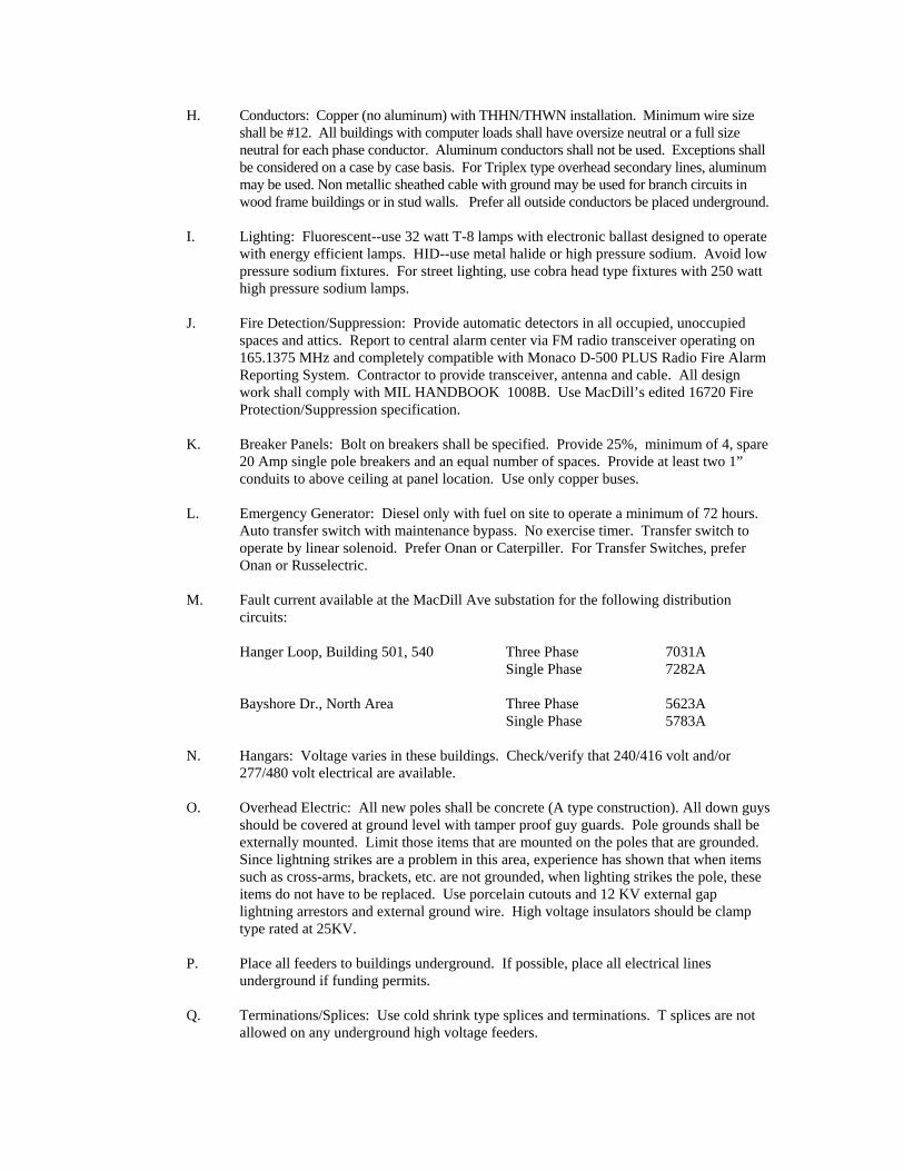
M. Fault current available at the MacDill Ave substation for the following distribution
circuits:
Hanger Loop, Building 501, 540 Three Phase 7031A Single Phase 7282A
Bayshore Dr., North Area Three Phase 5623A
Single Phase 5783A N. Hangars: Voltage varies in these buildings. Check/verify that 240/416 volt and/or
277/480 volt electrical are available. O. Overhead Electric: All new poles shall be concrete (A type construction). All down guys
should be covered at ground level with tamper proof guy guards. Pole grounds shall be externally mounted. Limit those items that are mounted on the poles that are grounded. Since lightning strikes are a problem in this area, experience has shown that when items such as cross-arms, brackets, etc. are not grounded, when lighting strikes the pole, these items do not have to be replaced. Use porcelain cutouts and 12 KV external gap lightning arrestors and external ground wire. High voltage insulators should be clamp type rated at 25KV.
P. Place all feeders to buildings underground. If possible, place all electrical lines
underground if funding permits. Q. Terminations/Splices: Use cold shrink type splices and terminations. T splices are not
allowed on any underground high voltage feeders.
R. All pad mounted switches shall be vacuum or SF6 type. Prefer all devices to be pad mounted.
S. Energy Conservation Iniatives:
1. Energy performance must be meeting or exceed the requirement of Energy
Technical letter 94-4, Energy Usage Criteria for Facilities in the Military Construction Program.
2. Use premium efficiency motors for 10 hp and above. 3. Use variable speed fans and pumps unless other alternative provide a lower life-
cycle-cost or special system constraint require constant speed equipment. 4. Lighting:
A. Occupancy sensors: Interface lighting controls and occupancy sensors
with the EMCS system (i.e. Building DDC system). Occupancy sensors in bathrooms and small rooms are not required to be connected to EMCS when not practical. Use occupancy sensor on: 1. All lighting systems with a connected load greater than 1,000
watts. 2. All Bathrooms 3. Any area that is frequently unoccupied during duty hours.
B. Incandescent lights: Use only when required for special dimming
application. Interlock dimmer system with conventional fluorescent lights to prevent both lighting systems from operating simultaneously.
C. Non-security outside lights: Interconnect outside lights and photo cells
with the EMCS system. Program the lights to shut off when not needed.
D. Exit signs: Use LED type exit signs.
T. All equipment that is susceptible to Year 2000 problems must contain manufacture’s literature certifying that the equipment meets all Year 200 Requirements.
V. - Communications
A. General: Facility design will provide for adequate wiring systems, adequate space for installation and maintenance of C-CS equipment and wiring.
1. A Communications Equipment Room (CER) is required for a facility having
significant C-CS requirements. Unoccupied facilities and small facilities such as guard houses, utility control buildings, storage bunkers, etc., will normally NOT require a CER. The CER normally serves as the entrance facility for all incoming C-CS ducts and service, and serves as the main location for C-CS equipment such as PABX’s, electronic key systems, main LAN hubs/routers/servers, etc. This equipment will not be housed in common use areas. Because of the equipment located here, the CER must be environmentally
controlled. The overhead lighting should be a minimum of 30 foot-candles at floor level. A. Location - The CER should be located on the 1st floor with an exterior
wall. Large CER’s should be provided with lockable double doors opening out or sliding (recommended total door opening size: 6' W x,8' H) without a center support to ensure large equipment can be easily moved into the room. CERs must not be collocated with other building utility services such as HVAC, Generators/Transformers, etc., due to the sensitivity of newer C-CS equipment to Electro-Magnetic Interference (EMI).
B. Power - The CER must have adequate power to support the C-CS
equipment. The minimum requirement is four 20 Amp dedicated branch circuits, but can be greater depending on the planned equipment for the room. The designer should coordinate power requirements with the base C-CS personnel and/or the designated Engineering and Installation (E&I) wing. In addition, the room should also have normal convenience outlets on all walls in accordance with the NEC and/or local code requirements.
C. Supporting Structures - As a minimum requirement the CER should
have ¾” by 8ft by 4 ft ,exterior grade plywood backboards (to accommodate the connecting blocks D-rings and standoff brackets) on two (2) adjacent walls. Both backboards should cover from one foot above the finished floor level to no less than seven foot above the finished floor level. The plywood backboards should be off-set from the wall by 3 ½” supported vertically, capable of supporting 300 lbs of wall mounted equipment. One of the plywood backboards , where the intra building cables terminate, will be hinged on each end, opening in the middle and latched in the middle. Depending on the C-CS requirements, a floor mounted Main Distribution Frame (MDF) may be required to support cable terminations.
D. Grounding - Grounding must meet the appropriate NEC requirements
and practices. As a minimum, provide a single-point ground for all Communications-Electronics equipment for the building within the CER. Provide a copper ground plate (bus bar with min. 6" H x 24" L) in the CER. The ground plate will be installed 7 inches above ground level on a wall (preferably an outside wall) within the CER. Provide a ground riser with a No.1 or larger wire directly connected to the provided ground plate with no taps. The resistance of the ground riser must be 5 ohms or less measured from the main ground point. All connections of wire-to-wire and/or wire-to-ground rod must be cad-welded. The designer should coordinate with the base Communications-Computer Systems Officer (CSO) to determine grounding requirements for more sensitive communications requirements.
E. Entrance Facilities - All facilities will have entrance conduits into the
CER with the minimum number as indicated in Table 1. Entrance conduits must have a minimal amount of 90 degree bends. If the number of 90 degree bends exceeds two, pull boxes must be installed. If the general area where the new facility is located is not served by a manhole (MH) and duct system or if the impact of the new facility will
greatly develop the area then a new MH/duct system should be designed to connect the facility to the nearest existing MH/duct system and be considered and included as a cost to the facility. See the USAF/LEE engineering technical letter (ETL) 87-9 and Technical Bulleting (TB) 95-03 for additional guidance. For projects where an extensive new MH/duct system will be required, it is critical that the CSO and 38 EIW E&I agency be consulted as soon as possible in the Design process.
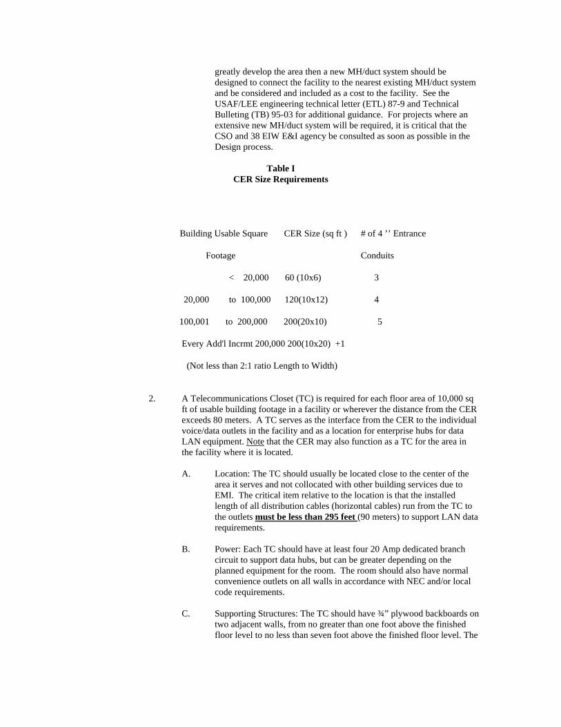
Table I
CER Size Requirements
Building Usable Square CER Size (sq ft ) # of 4 ’’ Entrance
Footage Conduits
< 20,000 60 (10x6) 3
20,000 to 100,000 120(10x12) 4
100,001 to 200,000 200(20x10) 5
Every Add'l Incrmt 200,000 200(10x20) +1
(Not less than 2:1 ratio Length to Width)
2. A Telecommunications Closet (TC) is required for each floor area of 10,000 sq
ft of usable building footage in a facility or wherever the distance from the CER exceeds 80 meters. A TC serves as the interface from the CER to the individual voice/data outlets in the facility and as a location for enterprise hubs for data LAN equipment. Note that the CER may also function as a TC for the area in the facility where it is located. A. Location: The TC should usually be located close to the center of the
area it serves and not collocated with other building services due to EMI. The critical item relative to the location is that the installed length of all distribution cables (horizontal cables) run from the TC to the outlets must be less than 295 feet (90 meters) to support LAN data requirements.
B. Power: Each TC should have at least four 20 Amp dedicated branch
circuit to support data hubs, but can be greater depending on the planned equipment for the room. The room should also have normal convenience outlets on all walls in accordance with NEC and/or local code requirements.
C. Supporting Structures: The TC should have ¾” plywood backboards on
two adjacent walls, from no greater than one foot above the finished floor level to no less than seven foot above the finished floor level. The

plywood on the wall where the intra-building conduits terminate should be offset 3 ½” from the wall
D. Grounding: Grounding must meet the appropriate NEC requirements
and practices. As a minimum, provide a No. 6 ground wire or larger connected with a direct home run to the ground plate in the CER. This grounding must be 10 ohms or less measured at the grounding point
E. Size: Minimum size for a TC is 6'X 4'. Door should be on one of the
lengthier walls. The TC size should be provided in accordance with (IAW) EIA/TIA-569, Chapter 7, Table 7.2-1.
F. Environmental Control: Because of the equipment located within, the
TC must be environmentally controlled. G. Lighting: The overhead lighting should be a minimum of 30 foot-
candles at floor level. 3. Conduits:
A. All outlets will be fed using conduits. The minimum size to serve a single
outlet box should be 1” inside diameter to allow installation of future copper and fiber optic cables.
B. In large buildings it is acceptable to use metallic raceway with hinged
access covers to contain the cables and branch individual conduits from the raceway to the outlets
C. Each conduit will only feed one outlet
4. Wiring:
A. Voice: All voice wiring should meet the minimum EIA/TIA Category 6
requirements. All cables will be run continuous from the outlet to either the TC or CER, with no breaks or interruptions. It is also mandatory for all cables to be identically numbered on each end. One voice cable will be terminated to two dual RJ-11 Printed Circuit Boards (PCB’s) at every outlet. One pair of the cable will terminate to each of the four RJ-11 jacks. Terminations in the CER and TC will be on 110 style blocks. The voice riser cables from the CER to each TC should be sized at a minimum of 30% over the total pair distribution planned for the TC rounded up to the next 100 pair count. The riser conduit design should include spare capacity for a second riser cable of equal size. Pinouts for the voice and data jacks will conform to the EIA/TIA 568B standard.
B. Data: All copper data wiring should meet the minimum EIA/TIA
Category 6 requirements.. All cables will be run continuous from the outlet to either the TC or CER, with no breaks or interruptions. It is also mandatory to number all cables identically on each end. Two Category 6 data cables will be run to each outlet. These cables will terminate on one dual RJ-45 PCB. Terminations in the CER and TC will be on Category 6 rated, RJ-45 patch panels with 110 terminations on the back.. Installed length of copper data cables must be less than 295 feet (90 meters).
C. Fiber Optic Cables: The minimum size fiber optic riser cable from the CER to each TC is 6 strands. Coordinate with the base CSO for additional requirements. The riser conduit design should include spare capacity for a second fiber optic cable of equal size. All fiber cabling must meet the minimum ANSI/EIA/TIA-492AAAA requirements.
D. Waivers: If requirements for terminations are waived by the base CSO,
leave one foot of cable at each outlet. In the CER leave enough slack on each cable so they touch the floor opposite the conduit ends.
E. Outlets - The design should provide for an outlet box of modular
design and support four voice and two data. outlets next to every electrical outlet or spaced eight feet apart depending on room size and function. The communications outlet will be no closer than 12” to the electrical outlet and no further than 18”, installed vertically in the same manner as electrical outlets such that the 4 1/2” sides of each outlet are perpendicular to the floor. If an area is designated to have modular furniture in the middle of a room, plan for one outlet for every two workstations. The designer should coordinate outlet requirements with the base CSO. Contact base CSO for specific outlet preferences. Communication wiring in prewired workstations, portable walls, modular offices and other items which are easily moved must be compatible with the wiring used elsewhere in the building and be funded as part of the movable items if the wiring outlets are integrally mounted or wiring is permanently installed.
VI. - Security Police (Types of work that Security Police are generally concerned with.)
A. Any work being conducted in Restricted or Controlled Areas. B. All flightline projects regardless of location or degree of work. C. Special purpose construction: Armories, Munitions, Fund storage areas; Drug
vault/storage areas; Secure Rooms/Vaults for classified storage. D. Facilities requesting/requiring alarms. E. Special purpose fencing. F. Effects project will have on traffic flow or road closures.
VII. - Safety
A. This Safety Guide Outline is provided for your use by 6 ARW Safety, 6 CES Fire
Department, and 6th Medical Group Bioenvironmental Engineering. B. This guide is designed to provide a general overview of safety items/issues for the A-E to
consider when developing a project as well as specific, supplemental information to serve as a quick reference, only, when used at the job site. Contractors are expected to comply with the safety requirements as stipulated in the applicable contract and requirements applicable to the environment and the work being performed. Applicable standards and regulations are available at Civil Engineering and the above agencies.
C. Wing Safety and Fire Department personnel may periodically visit your work site. If a discrepancy of a minor nature is discovered, it will be brought to the attention of the government representative who has been assigned to monitor the project. He/she will in turn advise you of the problem in need of corrective action. You are expected to comply with this request as soon as possible. In the event of a serious discrepancy and safety hazard found on the job, the Safety Office/Fire Department Inspector will notify the government representative for immediate action and correction.
D. The Occupational Safety and Health Agency (OSHA), which administers the Williams-
Steiger Occupational Safety and Health Act of 1970, has a regional office in Tampa, Florida. While fulfilling your contract, you are additionally open for a safety inspection by OSHA representatives. You are expected to abide by all federal regulations, especially, Public Law 91-596, Sect. (5)(a)(1); 29 CFR 1910; and 29 CFR 1926.
E. Safety-Related Telephone Numbers
1. Emergency Telephone Numbers
Operation Number Fire 911 Police 911 Medical 911
2. Business Telephone Numbers and Locations
Operation Number Location 6 ARW Safety 828-4652 Bldg 299 (MacDill AFB) Bioenvironmental 828-3534 Bldg 710 (MacDill AFB) Fire Department 828-4236 Bldg 26 (MacDill AFB) Security Forces 828-2000 Bldg 528 (MacDill AFB) 6 ARW Hospital 828-2333 Bldg 171 (MacDill AFB)
F. General Safety Requirements
1. “STUDY YOUR JOB FROM THE SAFETY ANGLE. Think before starting
work. Look around and search for hazards, then take precautions to prevent accidents from happening. Be sure you have all necessary protective equipment with you before you start to work. If you are in doubt about hazards or the proper protective clothing or equipment, consult your foreman.”
2. “Practice good housekeeping in your work area. Pick up tools. Do not leave
materials and scrap where they will be hazardous to other personnel, i.e., tripping hazards or sharp objects.”
3. “For your protection, obey all warning signs such as “Keep Out,” “No
Smoking,” “Eye Protection Required,” “Authorized Personnel Only,” and “Restricted Area.”
4. “Report any unsafe conditions or acts to your foreman immediately. Contact the
6 ARW Safety Office at 828-4652 if assistance is required.” 5. “Fighting or horseplay will not be tolerated.”
6. “Never jump from any elevated surface.” 7. “The handling of explosives is extremely dangerous. On all work of this nature,
consult your foreman.” 8. “Ensure that all personnel performing your work are advised of the heavy traffic
at MacDill AFB. They are to be briefed on abiding by the posted speed limits, respect “No Parking” signs, yield to emergency vehicles, and obey other appropriate road signs which govern traffic flow. Failure to obey will result in a driving citation issued by the MacDill Security Forces Squadron on a DD Form 1805.”
9. “Ensure that all personal protective equipment that is needed is provided and
used by your employees.” 10. “Confined Space Entry: Permits must be approved and signed by the 6 ARW
Safety Office, 6 ARW Fire Department, and the 6 ARW Bioenvironmental Engineering Office prior to entry. Also, your company must provide atmospheric monitoring capability as needed. 6 ARW will not provide this service to you.”
G. General Bioenvironmental Engineering Requirements
1. The contractor is responsible for OSHA compliance at the job site. Sometimes
the contractor’s activities may pose a health risk to Air Force Personnel in the area. If such a potential health threat should occur, the Bioenvironmental Engineering Office will work through the contractor monitor to help resolve the problem.
2. Many areas on MacDill have been designated as Hazardous Noise Areas. DoD
personnel are required to wear hearing protection in these areas. The Air Force noise standard is more conservative than OSHA’s (29 CFR 1910.95). Please contact the Bioenvironmental Engineering Office for noise level information.
3. Contractors must send in a chemical inventory and an MSDS for all chemicals
that will be brought onto the installation. This inventory must be coordinated through the HAZMART (828-2582). In the same manner, if the contractor has any concerns of Air Force chemical use in the construction area, that information can be obtained through the Bioenvironmental Engineering Office or the HAZMART.
4. If the contractor is going to bring any radioactive material, ionizing radiation
producing equipment, non-ionizing radiation producing equipment and/or lasers; coordination through the base Radiation Safety Officer (at the Bioenvironmental Engineering Office) prior to entering the installation is required. Also, compliance with all Nuclear Regulatory Commission (NRC) regulations is the contractors responsibility.
5. If the contractor breaks a water line during construction, the Bioenvironmental
Engineering Office must be notified immediately. Bioenvironmental Engineering will provide clearance sampling after the line has been repaired and disinfected.
6. All asbestos and lead based paint abatement, contact, disturbance, and/or
demolition must be done IAW all applicable Federal, State, and Local
regulations and guidelines. All contract workers must be trained in the proper handling of asbestos and lead based paint if the workers are performing this type of work. If, during the completion of the contract, workers come across a material that has not been identified as non-asbestos, and it can not be assumed that the material is not asbestos containing (e.g. wood, glass, etc.), the contract monitor must be notified prior to disturbance.
H. Emergency Medical Service
1. The 6 ARW Medical Group (Base Hospital) will respond to medical
emergencies on base. For contractor personnel needing emergency treatment, service will be provided, but is limited to stabilization of the injured. The contractor must provide for ongoing treatment at an off base facility. Services provided by our hospital must be reimbursed by the contractor.
IX. - Base Environmental
A. This organization is configured into 3 different sections for three areas of concern:
Compliance, Restoration, and Natural Resources. Respectively, when designing a project, these three areas should be taken into consideration. 1. Restoration: Restoration is concerned with areas that have been identified as
contaminated and/or are under restoration. Construction should not interfere with these sites and should be coordinated during the siting process prior to design. CEV can identify these sites. The site is not expected to contain contaminants, however, provisions should be allotted for possibility that contaminants are encountered. Coordinate with CEVR at site selection phase of projects.
2. Compliance: Ensures that contracts comply with local, county, state and federal
environmental regulations, with topics such as permits, asbestos, and lead-based paint. The requirements that they generally follow are those imposed by these organizations (i.e. the government generally doesn’t have their own regulations). A. Stormwater & Wastewater Permits: The regulatory authority for
stormwater permits is the South West Florida Water Management District. The regulatory authority for wastewater permits is the Environmental Protection Commission of Hillsborough County. Stormwater permits are needed anytime there is a project that has a parking lot constructed with it. In general, wastewater permits are needed anytime a project has a lift station constructed or in other words there is a connection to the sanitary sewer system that involves more than a clean-out. 1. Permits need to be submitted to 6 CES/CEVC when the
project is 100% designed, not right before the Notice to Proceed (NTP). This allows us to have time to get the 6 ARW/CC’s signature and submit it the regulators without holding up the project start date.
2. The A/E has to sign and seal the permit application. It must be
signed and sealed by the A/E before 6 ARW/CC can be expected to sign. Include with the permit application 4 copies
of permit application, plans, specifications, and calculations. Both EPCHC and SWFWMD require 4 copies, not one or two, and they should all be original signatures, not copies. EXCEPTION: By Federal Law the A/E does not have to seal the documents but still must sign. If the A/E does not seal the documents for following statement should be written, in quotations, immediately below the A/E signature and also where the P.E. stamp would be: “EXEMPT FROM SEAL PER FEDERAL REGULATION 17-4.05(3)”
3. Make sure 6 ARW/CC's name is correctly spelled. Also
ensure the correct address for 6 ARW/CC is included on the permit application (contact 6 CES/CEVC for examples of correct permit applications)
4. Include in the design (A/E) cost the permit application fees. 5. Permit Processing Time: It takes an average of 10-14 days to
get the permit application signed by 6 ARW/CC. The regulators have 30 days to “respond”, not “approve”, the application, although it's usually more like 60 if they have questions for the A/E. This takes us out to about 2-1/2 months to get a permit in-hand for the contractor once the permit application package has been received from the A/E. In most instances there are questions from the regulators that must be addressed before they will issue a permit, further delaying the approval process. (Note: every time the regulators have questions, the processing clock resets.)
6. With respect to stormwater permits: The A/E bares full
responsibility to accurately conceive and design the retention ponds and/or swales based on acceptable practices for design as endorsed by SWFWMD and the Florida Department of Environmental Protection (FDEP). Ponds and swales shall incorporate design guidelines set forth in the SWFWMD Environmental Resource Permitting Information Manual (Feb 96). Modeling of existing and proposed conditions shall be accomplished through the use of the Basin Runoff Networking (BRN) Program or acceptable equivalent. Design calculations sizing the retention ponds and/or swales shall be based on, but not limited to, the following criteria. A. A minimum of two (2) 15-foot Standard Penetration
Test (SPT) borings shall be performed at the proposed retention pond/swale site(s).
B. Both vertical and horizontal hydraulic conductivities
of the soil shall be conducted, not just vertical conductivities.
A/E shall bare full responsibility for providing timely and
accurate responses to requests from SWFWMD upon receipt of permit application. By law the A/E has thirty (30) days to
respond to the requests, after which time the permit may be denied if a response has not been received by SWFWMD.
7. With respect to sanitary sewer permits: The A/E bares full
responsibility to accurately conceive and design the proposed sanitary system and/or modifications to the existing system(s) based on acceptable practices for design as endorsed by the Environmental Protection Commission of Hillsborough County (EPCHC) and the Florida Department of Environmental Protection (FDEP). A/E shall bare full responsibility for providing timely and accurate responses to requests from EPCHC and FDEP upon receipt of permit application. By law the A/E has thirty (30) days to respond to the requests, after which time the permit may be denied if a response has not been received by EPCHC and FDEP.
B. Asbestos: Design firms designing projects that will involve
constructing new buildings or other structures or potentially modifying existing buildings or other structures at MacDill AFB shall address the subject of asbestos. New projects plans and specifications shall stipulate that no asbestos containing materials will be used in any construction at MacDill AFB. The design phase of projects for modifying existing structures located at MacDill AFB shall include a complete or partial asbestos survey of the facility to determine if asbestos containing material (ACM) is present in any part of the structure that will be modified or disturbed. The construction phase of projects for modifying existing structures located at MacDill AFB shall include abatement, encapsulation, enclosure or repair of ACM as necessary. All asbestos design projects concerning MacDill AFB shall be coordinated with Roy Kerns of the Civil Engineer Squadron Environmental Flight, 6CES/CEVC.
C. Air Quality: Design firms working on projects that involve the
creation or changing in any way of an air source located at MacDill AFB shall coordinate with the Environmental Protection Commission of Hillsborough County (EPCHC) through 6 CES/CEVC to modify the existing air operating permit or, for a new air source, apply for a construction permit. The cost of any fees involved shall be included in the design firms proposal with MacDill AFB for the particular project. Air sources include, but are not limited to, internal combustion sources (boilers), external combustion sources (generators and other internal combustion driven types of equipment), woodworking shops, paint spray booths, fuel storage and dispensing operations, welding operations, degreasers and emitters of ozone depleting substances and/or hazardous air pollutants (HAPS). All air permit activity concerning MacDill AFB shall be coordinated with Roy Kerns of the Civil Engineer Squadron Environmental Flight, 6CES/CEV.
D. Lead-Based Paint: Contracts/Contractors engaged in demolition,
construction, renovation, or any other services involving lead-based paint surfaces shall comply with Air Force Standards, applicable Federal, State and Local codes and regulations. The design phase of projects for modifying existing structures located at MacDill AFB shall include a complete or partial lead-based survey of the facility to determine if lead-based paint is present in any part of the structure that
will be modified or disturbed. The construction phase of projects for modifying existing structures located at MacDill AFB shall include abatement, encapsulation, enclosure or repair of lead-based paint as necessary. The contractor shall ensure workers are informed of and protected with the necessary protective equipment, in accordance with OSHA regulations 29 CFR1926.62, 1910.1025 and 1910.134. All work will be accomplished by trained and certified personnel in lead-based paint operations. All contractor work plans shall address abatement/encapsulation requirements, paint removal, material storage, containing and controlling lead dust and debris, daily and final cleanup, worker and occupant protection, inspecting and testing requirements, waste storage and disposal requirements, and recordkeeping and notification requirements. Coordination with 6 CES/CEV is mandatory prior to initiating any contract involving lead-base paint.
E. Affirmative Procurement: All Contracts/contractors providing goods
and/or services to MacDill AFB shall be reviewed for EPA Guideline items regarding building materials, supplies, products and specify percentages of recycled-content being used/supplied to the government. Service contract managers will also review all contract specifications that apply to EPA Guideline Items in accordance with The Air Force Affirmative Procurement Program, Executive Order 12873, Section 6002 of Resource Conservation and Recovery Act, and the FAR prior to the implementation of the contract.
F. Hazardous Materials Management: For each contract vehicle involving
the use of hazardous materials on MacDill AFB, a requirement must be included for the contractor to identify and report hazardous material usage to the contracting officer and HAZMART (6 SUPS/LGSDH). Contractors are required to maintain copies of Material Safety Data Sheets (MSDSs) for all hazardous materials used on MacDill AFB at the job site. All hazardous materials are to be used up in the process and all unused materials will be inventoried at HAZMART. Site specific spill plans must be developed, submitted, and approved by 6 CES/CEVC prior to work commencing and will address hazardous waste storage, if applicable.
G. Hazardous Waste: Contractors are responsible for the identification,
characterization, storage, and disposal of any waste that may be regulated under the Resource Conservation and Recovery Act (RCRA), hazardous waste regulations, 40 CFR 260-279. 6 CES/CEVC must be coordinated with prior to the generation of any hazardous waste. Any shipments of hazardous waste will be coordinated and approved through 6 CES/CEVC prior to shipment off-base for disposal. All manifests/land disposal restrictions must be signed by 6 CES/CEVC prior to shipment off-base.
H. Underground and Aboveground Storage Tanks: USTs and ASTs shall
comply with all requirements for new systems as stated in Florida Administrative Code (FAC) 62-762, Aboveground Storage Tank Systems. In addition, unless compelling reasons exist, USTs shall not be installed. ASTs shall be double walled. All tanks, piping, and associated equipment shall be Florida Department of Environmental Protection approved.
I. Solid Waste/Recycling: All construction contractors will use Waste Management roll-off dumpsters. All demolition debris that can be salvaged and resold shall be included in the construction contract specifications. The proceeds from the sales shall go to reducing the cost of the construction contract. The total tonnage recycled from the project shall be reported to CEVC. Construction and demolition waste comprises approximately 20% to 30% of all the solid waste generated at MacDill, a large part of this waste stream is recyclable. The metal, dry wall, wood and the concrete are all recyclable. We require that construction and demolition contractors provide with their proposal a recycling plan to properly depose of this valuable material. The moneys saved can go to reduce the cost of the contract, or generate funds for the RRRP. If the contractor went to pay the base for resaleable items such as air conditioners, cabinets, hot water heaters, bath room fixtures, etc. The estimated resale value shall be reduced from the cost of the contract or back to the base recycling program RRRP fund. If the contractor does not wish to bid on these items, we shall have a provision in the contract to have these commodities removed and transported to DRMO for government resale. The Solid Waste Manager/ Recycling Coordinator shall take a active part in the contracting planning process to assure that the government gets the best offset for this material.
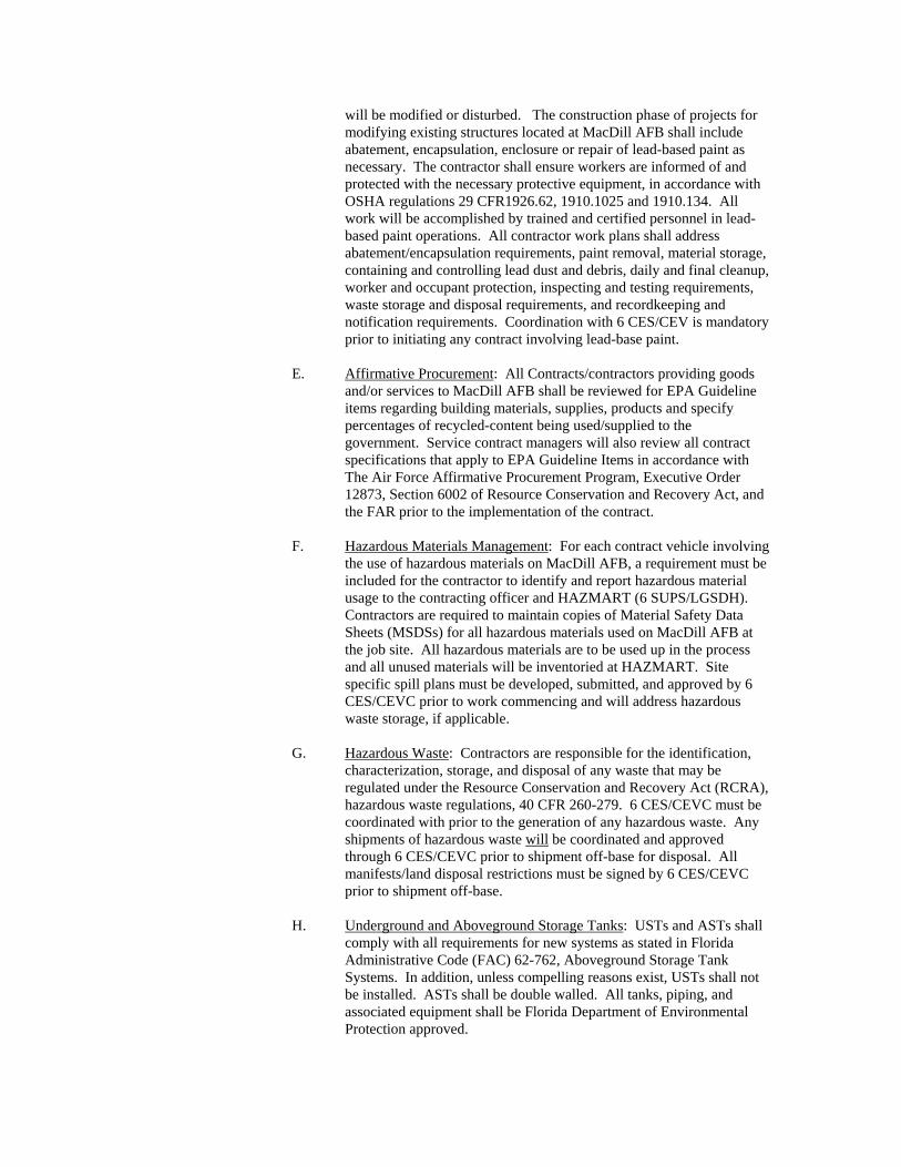
3. Natural and Cultural Resources: This section protects MacDill AFB’s natural
resources which usually involves building preservation, archeological site protection, protection of endangered species, wetlands, etc. This section is also involved with compliance with the National Environmental Policy Act. CEV can identify how these items must be considered/dealt with. Generally, all new construction requires the completion of section I of an AF Form 813 by the proponent (user/requester). Any project involving the renovation of a historic building will require coordination with State Historic Preservation Office (SHPO). Before 6 CES/CEV can coordinate with the SHPO they will require from 6 CES/CEC an engineering assessment.
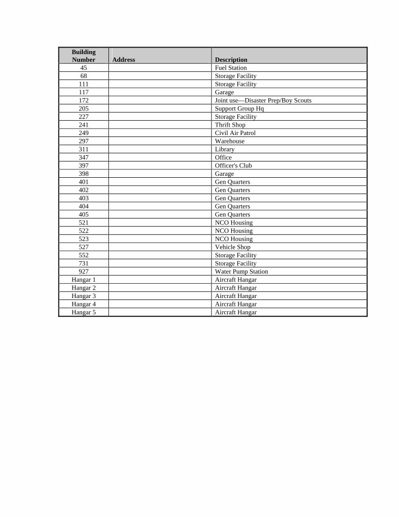
Historical Buildings:
Building Number
Address
Description
11 Storage Facility 12 Maintenance Shop 26 Fire Station 27 Community Facility 28 Product Plt 29 Maintenance Shop 30 Engineering Adm 31 Maintenance Shop 32 Maintenance Shop 33 Maintenance Shop 34 Ce Storage Shed 35 Maintenance Shop 37 Water Tower 41 Theater 42 Pme Laboratory
Building Number
Address
Description
45 Fuel Station 68 Storage Facility
111 Storage Facility 117 Garage 172 Joint use—Disaster Prep/Boy Scouts 205 Support Group Hq 227 Storage Facility 241 Thrift Shop 249 Civil Air Patrol 297 Warehouse 311 Library 347 Office 397 Officer's Club 398 Garage 401 Gen Quarters 402 Gen Quarters 403 Gen Quarters 404 Gen Quarters 405 Gen Quarters 521 NCO Housing 522 NCO Housing 523 NCO Housing 527 Vehicle Shop 552 Storage Facility 731 Storage Facility 927 Water Pump Station
Hangar 1 Aircraft Hangar Hangar 2 Aircraft Hangar Hangar 3 Aircraft Hangar Hangar 4 Aircraft Hangar Hangar 5 Aircraft Hangar
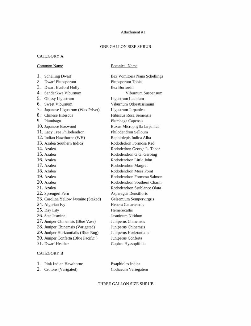
Attachment #1
ONE GALLON SIZE SHRUB CATEGORY A Common Name Botanical Name 1. Schelling Dwarf Ilex Vomitoria Nana Schellings 2. Dwarf Pittosporum Pittosporum Tobia 3. Dwarf Burford Holly Ilex Burfordil 4. Sandankwa Viburnum Viburnum Suspensum 5. Glossy Ligustrum Ligustrum Lucidum 6. Sweet Viburnum Viburnum Odoratissimum 7. Japanese Ligustrum (Wax Privet) Ligustrum Jarpanica 8. Chinese Hibiscus Hibiscus Rosa Semensis 9. Plumbago Plumbaga Capensis 10. Japanese Boxwood Buxus Microphylla Jarpanica 11. Lacy Tree Philodendron Philodendron Selloum 12. Indian Hawthorne (WH) Raphiolepis Indica Alba 13. Azalea Southern Indica Rododedron Formosa Red 14. Azalea Rododedron George L. Tabor 15. Azalea Rododendron G.G. Gerbing 16. Azalea Rododendron Little John 17. Azalea Rododendron Margret 18. Azalea Rododendron Moss Point 19. Azalea Rododendron Formosa Salmon 20. Azalea Rododendron Southern Charm 21. Azalea Rododendron Ssublance Olata 22. Sprengeri Fern Asparagus Densifloris 23. Carolina Yellow Jasmine (Staked) Gelsemium Sempervirgris 24. Algerian Ivy Heoera Canariemsis 25. Day Lily Hemerocallis 26. Star Jasmine Jasminum Nitidum 27. Juniper Chinemsis (Blue Vase) Juniperus Chinemsis 28. Juniper Chinemsis (Varigated) Juniperus Chinemsis 29. Juniper Horizontialis (Blue Rug) Juniperus Horizontialis 30. Juniper Conferta (Blue Pacific ) Juniperus Conferta 31. Dwarf Heather Cuphea Hyssopifolia CATEGORY B 1. Pink Indian Hawthorne Pxaphioles Indica 2. Crotons (Varigated) Codiaeum Variegatem
THREE GALLON SIZE SHRUB
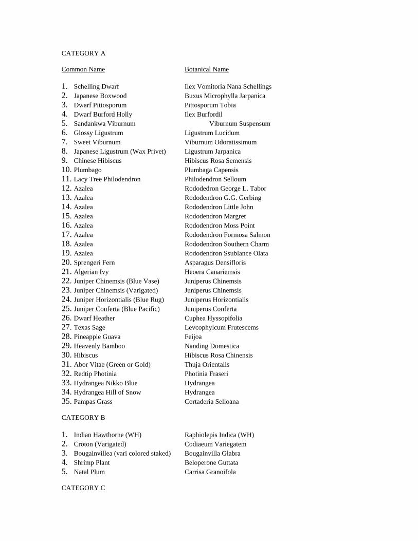
CATEGORY A Common Name Botanical Name 1. Schelling Dwarf Ilex Vomitoria Nana Schellings 2. Japanese Boxwood Buxus Microphylla Jarpanica 3. Dwarf Pittosporum Pittosporum Tobia 4. Dwarf Burford Holly Ilex Burfordil 5. Sandankwa Viburnum Viburnum Suspensum 6. Glossy Ligustrum Ligustrum Lucidum 7. Sweet Viburnum Viburnum Odoratissimum 8. Japanese Ligustrum (Wax Privet) Ligustrum Jarpanica 9. Chinese Hibiscus Hibiscus Rosa Semensis 10. Plumbago Plumbaga Capensis 11. Lacy Tree Philodendron Philodendron Selloum 12. Azalea Rododedron George L. Tabor 13. Azalea Rododendron G.G. Gerbing 14. Azalea Rododendron Little John 15. Azalea Rododendron Margret 16. Azalea Rododendron Moss Point 17. Azalea Rododendron Formosa Salmon 18. Azalea Rododendron Southern Charm 19. Azalea Rododendron Ssublance Olata 20. Sprengeri Fern Asparagus Densifloris 21. Algerian Ivy Heoera Canariemsis 22. Juniper Chinemsis (Blue Vase) Juniperus Chinemsis 23. Juniper Chinemsis (Varigated) Juniperus Chinemsis 24. Juniper Horizontialis (Blue Rug) Juniperus Horizontialis 25. Juniper Conferta (Blue Pacific) Juniperus Conferta 26. Dwarf Heather Cuphea Hyssopifolia 27. Texas Sage Levcophylcum Frutescems 28. Pineapple Guava Feijoa 29. Heavenly Bamboo Nanding Domestica 30. Hibiscus Hibiscus Rosa Chinensis 31. Abor Vitae (Green or Gold) Thuja Orientalis 32. Redtip Photinia Photinia Fraseri 33. Hydrangea Nikko Blue Hydrangea 34. Hydrangea Hill of Snow Hydrangea 35. Pampas Grass Cortaderia Selloana CATEGORY B 1. Indian Hawthorne (WH) Raphiolepis Indica (WH) 2. Croton (Varigated) Codiaeum Variegatem 3. Bougainvillea (vari colored staked) Bougainvilla Glabra 4. Shrimp Plant Beloperone Guttata 5. Natal Plum Carrisa Granoifola CATEGORY C
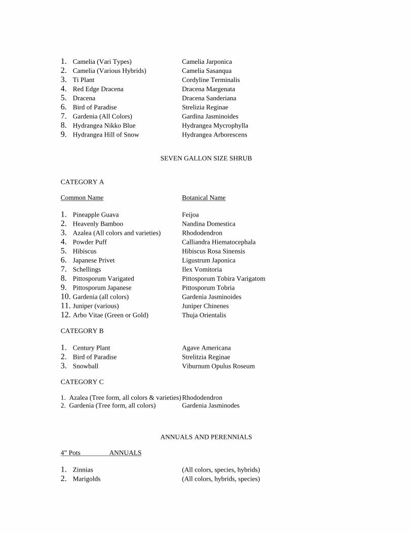
1. Camelia (Vari Types) Camelia Jarponica 2. Camelia (Various Hybrids) Camelia Sasanqua 3. Ti Plant Cordyline Terminalis 4. Red Edge Dracena Dracena Margenata 5. Dracena Dracena Sanderiana 6. Bird of Paradise Strelizia Reginae 7. Gardenia (All Colors) Gardina Jasminoides 8. Hydrangea Nikko Blue Hydrangea Mycrophylla 9. Hydrangea Hill of Snow Hydrangea Arborescens
SEVEN GALLON SIZE SHRUB CATEGORY A Common Name Botanical Name 1. Pineapple Guava Feijoa 2. Heavenly Bamboo Nandina Domestica 3. Azalea (All colors and varieties) Rhododendron 4. Powder Puff Calliandra Hiematocephala 5. Hibiscus Hibiscus Rosa Sinensis 6. Japanese Privet Ligustrum Japonica 7. Schellings Ilex Vomitoria 8. Pittosporum Varigated Pittosporum Tobira Varigatom 9. Pittosporum Japanese Pittosporum Tobria 10. Gardenia (all colors) Gardenia Jasminoides 11. Juniper (various) Juniper Chinenes 12. Arbo Vitae (Green or Gold) Thuja Orientalis CATEGORY B 1. Century Plant Agave Americana 2. Bird of Paradise Strelitzia Reginae 3. Snowball Viburnum Opulus Roseum CATEGORY C 1. Azalea (Tree form, all colors & varieties) Rhododendron 2. Gardenia (Tree form, all colors) Gardenia Jasminodes
ANNUALS AND PERENNIALS 4” Pots ANNUALS 1. Zinnias (All colors, species, hybrids) 2. Marigolds (All colors, hybrids, species)
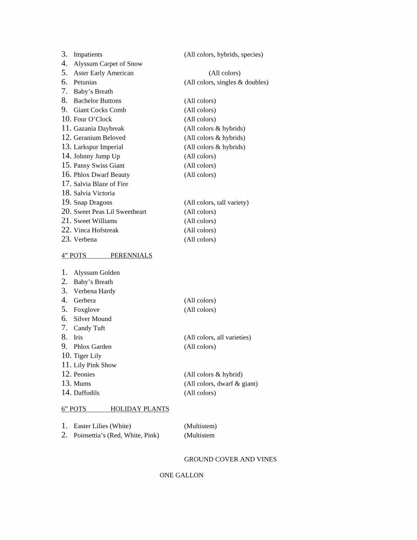
3. Impatients (All colors, hybrids, species) 4. Alyssum Carpet of Snow 5. Aster Early American (All colors) 6. Petunias (All colors, singles & doubles) 7. Baby’s Breath 8. Bachelor Buttons (All colors) 9. Giant Cocks Comb (All colors) 10. Four O’Clock (All colors) 11. Gazania Daybreak (All colors & hybrids) 12. Geranium Beloved (All colors & hybrids) 13. Larkspur Imperial (All colors & hybrids) 14. Johnny Jump Up (All colors) 15. Pansy Swiss Giant (All colors) 16. Phlox Dwarf Beauty (All colors) 17. Salvia Blaze of Fire 18. Salvia Victoria 19. Snap Dragons (All colors, tall variety) 20. Sweet Peas Lil Sweetheart (All colors) 21. Sweet Williams (All colors) 22. Vinca Hofstreak (All colors) 23. Verbena (All colors) 4” POTS PERENNIALS 1. Alyssum Golden 2. Baby’s Breath 3. Verbena Hardy 4. Gerbera (All colors) 5. Foxglove (All colors) 6. Silver Mound 7. Candy Tuft 8. Iris (All colors, all varieties) 9. Phlox Garden (All colors) 10. Tiger Lily 11. Lily Pink Show 12. Peonies (All colors & hybrid) 13. Mums (All colors, dwarf & giant) 14. Daffodils (All colors) 6” POTS HOLIDAY PLANTS 1. Easter Lilies (White) (Multistem) 2. Poinsettia’s (Red, White, Pink) (Multistem
GROUND COVER AND VINES
ONE GALLON
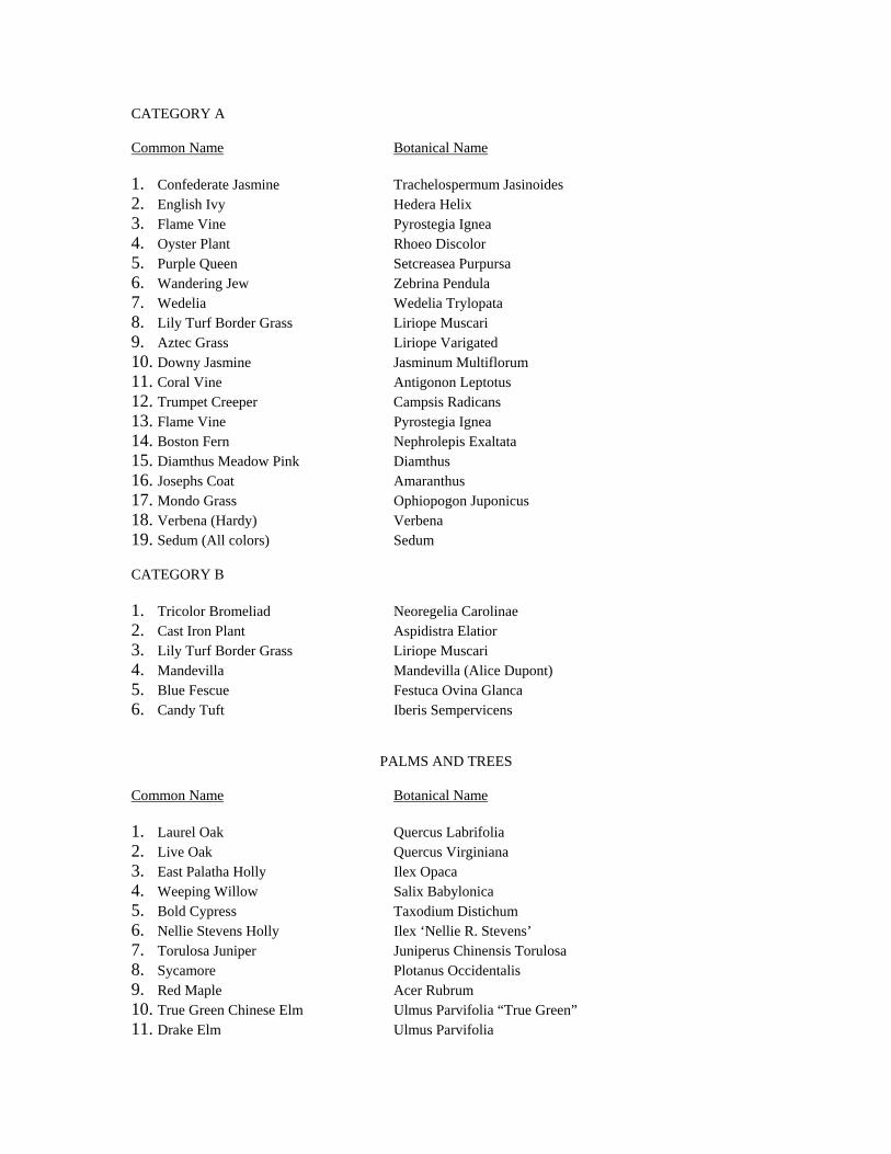
CATEGORY A Common Name Botanical Name 1. Confederate Jasmine Trachelospermum Jasinoides 2. English Ivy Hedera Helix 3. Flame Vine Pyrostegia Ignea 4. Oyster Plant Rhoeo Discolor 5. Purple Queen Setcreasea Purpursa 6. Wandering Jew Zebrina Pendula 7. Wedelia Wedelia Trylopata 8. Lily Turf Border Grass Liriope Muscari 9. Aztec Grass Liriope Varigated 10. Downy Jasmine Jasminum Multiflorum 11. Coral Vine Antigonon Leptotus 12. Trumpet Creeper Campsis Radicans 13. Flame Vine Pyrostegia Ignea 14. Boston Fern Nephrolepis Exaltata 15. Diamthus Meadow Pink Diamthus 16. Josephs Coat Amaranthus 17. Mondo Grass Ophiopogon Juponicus 18. Verbena (Hardy) Verbena 19. Sedum (All colors) Sedum CATEGORY B 1. Tricolor Bromeliad Neoregelia Carolinae 2. Cast Iron Plant Aspidistra Elatior 3. Lily Turf Border Grass Liriope Muscari 4. Mandevilla Mandevilla (Alice Dupont) 5. Blue Fescue Festuca Ovina Glanca 6. Candy Tuft Iberis Sempervicens
PALMS AND TREES Common Name Botanical Name 1. Laurel Oak Quercus Labrifolia 2. Live Oak Quercus Virginiana 3. East Palatha Holly Ilex Opaca 4. Weeping Willow Salix Babylonica 5. Bold Cypress Taxodium Distichum 6. Nellie Stevens Holly Ilex ‘Nellie R. Stevens’ 7. Torulosa Juniper Juniperus Chinensis Torulosa 8. Sycamore Plotanus Occidentalis 9. Red Maple Acer Rubrum 10. True Green Chinese Elm Ulmus Parvifolia “True Green” 11. Drake Elm Ulmus Parvifolia
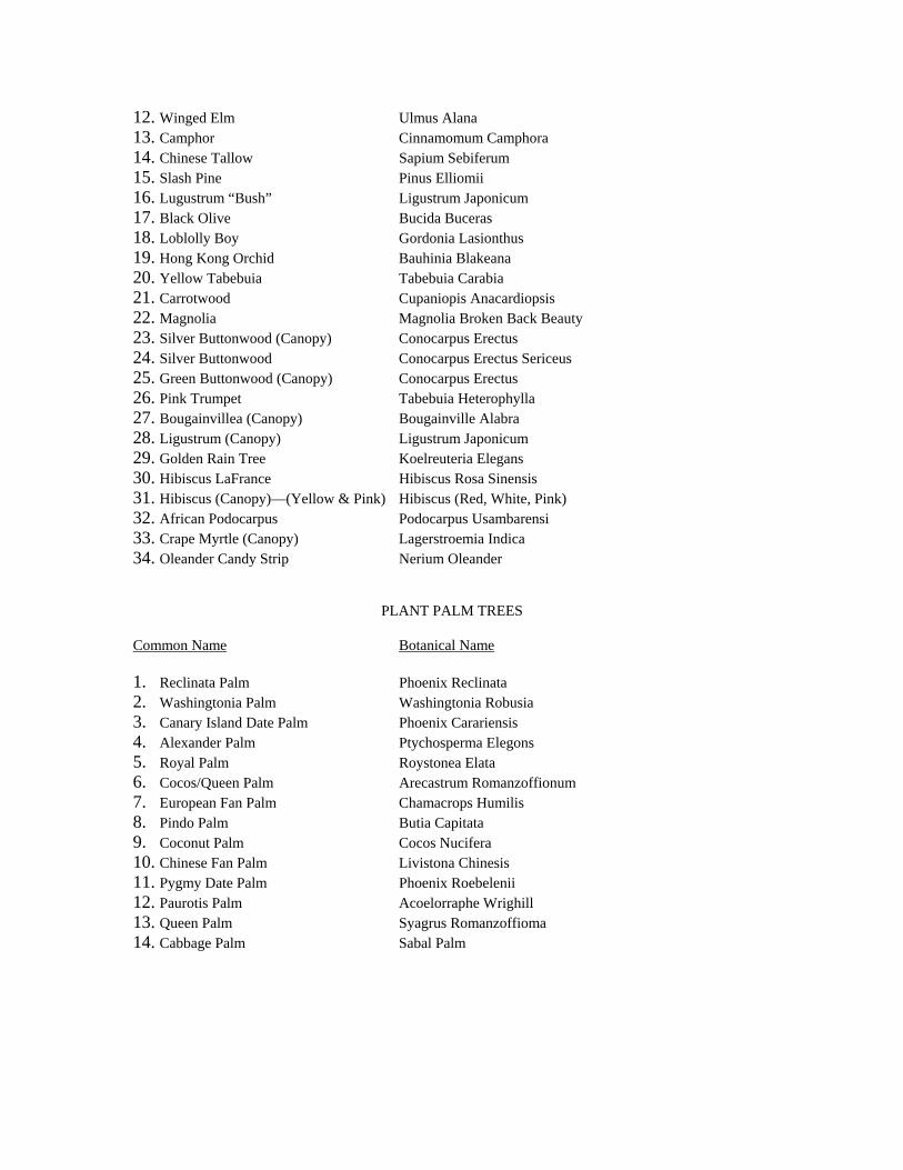
12. Winged Elm Ulmus Alana 13. Camphor Cinnamomum Camphora 14. Chinese Tallow Sapium Sebiferum 15. Slash Pine Pinus Elliomii 16. Lugustrum “Bush” Ligustrum Japonicum 17. Black Olive Bucida Buceras 18. Loblolly Boy Gordonia Lasionthus 19. Hong Kong Orchid Bauhinia Blakeana 20. Yellow Tabebuia Tabebuia Carabia 21. Carrotwood Cupaniopis Anacardiopsis 22. Magnolia Magnolia Broken Back Beauty 23. Silver Buttonwood (Canopy) Conocarpus Erectus 24. Silver Buttonwood Conocarpus Erectus Sericeus 25. Green Buttonwood (Canopy) Conocarpus Erectus 26. Pink Trumpet Tabebuia Heterophylla 27. Bougainvillea (Canopy) Bougainville Alabra 28. Ligustrum (Canopy) Ligustrum Japonicum 29. Golden Rain Tree Koelreuteria Elegans 30. Hibiscus LaFrance Hibiscus Rosa Sinensis 31. Hibiscus (Canopy)—(Yellow & Pink) Hibiscus (Red, White, Pink) 32. African Podocarpus Podocarpus Usambarensi 33. Crape Myrtle (Canopy) Lagerstroemia Indica 34. Oleander Candy Strip Nerium Oleander
PLANT PALM TREES Common Name Botanical Name 1. Reclinata Palm Phoenix Reclinata 2. Washingtonia Palm Washingtonia Robusia 3. Canary Island Date Palm Phoenix Carariensis 4. Alexander Palm Ptychosperma Elegons 5. Royal Palm Roystonea Elata 6. Cocos/Queen Palm Arecastrum Romanzoffionum 7. European Fan Palm Chamacrops Humilis 8. Pindo Palm Butia Capitata 9. Coconut Palm Cocos Nucifera 10. Chinese Fan Palm Livistona Chinesis 11. Pygmy Date Palm Phoenix Roebelenii 12. Paurotis Palm Acoelorraphe Wrighill 13. Queen Palm Syagrus Romanzoffioma 14. Cabbage Palm Sabal Palm
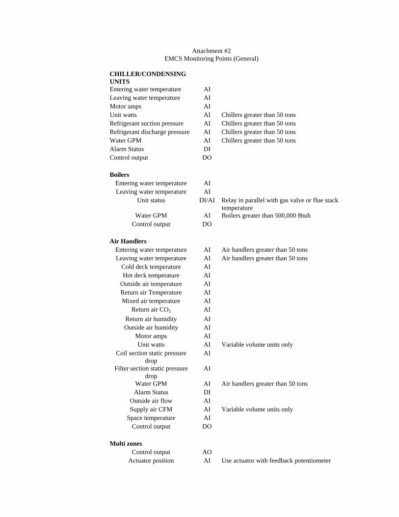
Attachment #2 EMCS Monitoring Points (General)
CHILLER/CONDENSING UNITS Entering water temperature AI Leaving water temperature AI Motor amps AI Unit watts AI Chillers greater than 50 tons Refrigerant suction pressure AI Chillers greater than 50 tons Refrigerant discharge pressure AI Chillers greater than 50 tons Water GPM AI Chillers greater than 50 tons Alarm Status DI Control output DO Boilers
Entering water temperature AI Leaving water temperature AI
Unit status DI/AI Relay in parallel with gas valve or flue stack temperature
Water GPM AI Boilers greater than 500,000 Btuh Control output DO
Air Handlers
Entering water temperature AI Air handlers greater than 50 tons Leaving water temperature AI Air handlers greater than 50 tons
Cold deck temperature AI Hot deck temperature AI
Outside air temperature AI Return air Temperature AI Mixed air temperature AI
Return air CO2 AI Return air humidity AI Outside air humidity AI
Motor amps AI Unit watts AI Variable volume units only
Coil section static pressure drop
AI
Filter section static pressure drop
AI
Water GPM AI Air handlers greater than 50 tons Alarm Status DI
Outside air flow AI Supply air CFM AI Variable volume units only
Space temperature AI Control output DO
Multi zones
Control output AO Actuator position AI Use actuator with feedback potentiometer
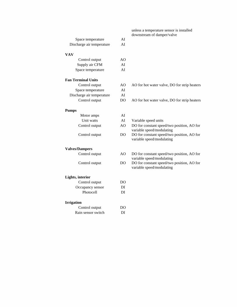
unless a temperature sensor is installed downstream of damper/valve
Space temperature AI Discharge air temperature AI
VAV
Control output AO Supply air CFM AI
Space temperature AI Fan Terminal Units
Control output AO AO for hot water valve, DO for strip heatersSpace temperature AI
Discharge air temperature AI Control output DO AO for hot water valve, DO for strip heaters
Pumps
Motor amps AI Unit watts AI Variable speed units
Control output AO DO for constant speed/two position, AO for variable speed/modulating
Control output DO DO for constant speed/two position, AO for variable speed/modulating
Valves/Dampers
Control output AO DO for constant speed/two position, AO for variable speed/modulating
Control output DO DO for constant speed/two position, AO for variable speed/modulating
Lights, interior
Control output DO Occupancy sensor DI
Photocell DI Irrigation
Control output DO Rain sensor switch DI