mab 431-68 - ksc corrosion technology laboratory home · of several alloys- aisi types 304,304l,...
TRANSCRIPT

KSC FORM 10-12 L4/06)
M A B 4 3 1 - 6 8
(Interi rn, Report)
CORROSION STUDY OF BARE AND COATED
S T A I N L E S S S T E E L
Prepared by
MATERIALS TESTING BRANCH( S O - L A B - 4 , M S O B , R m 1 2 1 3 )Analytical Laboratories Division
Kennedy Space Center, Florida 32899
February 197 1
NASA-PAFB APR/IO
. i
APPROVAL
M A B 4 3 1 - 6 8
( I n t e r i m R e p o r t )
CORROSIONSTUDYOFBAREANDCOATED
S T A I N L E S S S T E E L
PREPARED BY:
CONCURRENCE:
APPROVAL:
J .D. Morrison, NASA/MTB
C . L . SpringTield lOASAChief, Materials kesting Branch
H .G’. JohnsoW, NASAChief, Analytical Laboratories Division
i / i i

ABSTRACT . \
This report covers the work accomplished from February 1968, to date on aprogram, conducted for the Mechanical Design Division by the MaterialsTesting Branch, to evaluate the performance of.austenitic stainless steelalloys used in fluid systems lines at KSC. Need for the program was dic-tated by the occurrence of numerous failures of stainless steel hardware,caused by pitting and stress-corrosion cracking, over the past several years.Tests have been conducted to determine the inherent corrosion susceptibilityof several alloys - AISI Types 304,304L, 316,316L, 321 and 347 -and to evaluate the effectiveness of certain sacrificial-type protective coat-ings in preventing corrosion failures. The test samples, both unprotected .
and coated, have primarily been tubing sections and tubing assembliesemploying 37”-flare fittings. Samples were placed in racks approximately100 yards above high-tide line at Cape Kennedy. The racks were designedto provide complete exposure of half of each tubing sample and shelter fromdirect rain impingements of the other half. Protective coatings and treat-ments evaluated include organic- and inorganic-base zinc-rich paints, analuminum-filled proprietary coating, and periodic surface treatment with aphosphoric acid wash.
General conclusions reached at this point in the program are as follows:
1 .
2 .
3 .
4 .
5 .
All of the unprotected tubing samples, regardless of alloy type,showed evidence of pitting initiation after about two-weeksexposure at the beach test site.
Samples of Types 321 and 347 appear to develop a larger pitpopulation than the other alloys.
The deepest pit penetration (about 65% of the wall thickness)that has been discovered in the bare samples examined to datehas occurred in Type 3 16 tubing. However, it is probable thatactual pitting rate is independent of alloy type and that no oneof the alloys evaluated has appreciably better resistance to pitpenetration than the others.
The deepest pitting generally occurred in the sheltered portionof the tubing samples, probably because of the retention ofdeposits from salt fogs.
Zinc-rich coatings, both inorganic-base and organic-base, andan aluminum-filled coating, have afforded sacrificial protectionto the stainless steels against pitting, for as long as 28 months,and against stress-corrosion cracking of fittings, for as long as12 months. It is believed that a much longer effective coatinglife can be expected.
i i i / i v

TABLE OF CONTENTS
Paragraph Title ’ Page
1 . 0 Introduction. . . . . . . . . . . . . . . . . . . . . . . i . . . 12 . 0 Materials and Procedures . . . . . . . . . . . . . . . . . . . 73 .o Resul ts . . . . . . . . . . . . . . . . . . . . . . . . . . . . . 1 73 . 1 Metallurgical Analyses of Initial Materials, . . . . . . . . . . 1 73 . 1 . 1 Intergranular Embrittlement. . . . . . . . . . . . . . . . . . . 1 73 . 1 . 2 Non-Metallic Inclusions . . . . . . . . . . . . . . . . . . . . 1 7.3.1.3 Grain Size . . . . . . . . . . . . . . . . . . . . . . . . . . . 1 73 . 2 Visual Inspection of Exposure Samples . . . . . . . . . . . . 1 73 . 3 Metallurgical Analyses of Exposed Samples. . . . . . . . . . 2 94 . 0 Discussion . . . . . . . . . . . . . . . . . . . . . . . . . . . 4 34 . 1 Pitting Corrosion . . . . . . . . . f . . . . . . . . . . . . . . 4 34 . 2 Stress-Corrosion Cracking . . . . . . . . . . . . . . . . . . . 4 55 . 0 Conclusions . . . . . . . . . . . . . . . . . . . . . . . . . . . 4 6
A#APPENDIX A A - l
APPENDIX B B - l
Figure Ti t le
1
2
3
4
5
6
7
LIST OF ILLUSTRATIONS
Page
Perforation of Stainless Steel Tubing Used in High-PressureOxygen System on Astronauts’ Transfer Van. . . . . . . . . . 4Perforation of Stainless Steel Tubing Used in GaseousHydrogen Line at Complex 34 . . . . . . . . . . . . . . . . . 5Cracked B-Nut Sleeve From Control Console Line, MobileLauncher Service Arm 8, Complex 39. . . . . . . . . . . . . 6Corrosion Test Rack Number 3 With Tubing Samples at CapeKennedy Beach Test Site . . . . . . . . . . . . . . . . . . . 12Tubing Samples in Sheltered Section of Rack Number 3After 3-Months Exposure . . . . . . . . . . . . . . . . . . . 2 2Tubing Samples in Sheltered Section of Rack Number 3After 3-Months Exposure . . . . . . . . . . . . . . . . . . . 2 3Bare and Organic-Zinc Coated Samples in Exposed Sectionof Rack Number 3 . . . . . . . . . . . . . . . . . . . . . . . 2 4
V’

.
Figure
8
9
10
11
- 12
13
14
15
16
17
18
19
20
21
22
2324
LIST OF ILLUSTRATIONS (Continued)
T i t l e * Page
Bare and Organic-Zinc Coated Samples in Sheltered Sectionof Rack Number 3. . . . . . . . . . . . . . . . . . . . . . .Coated Samples in Exposed Section of Rack Number 4 Afterlo-Months Exposure. . . . . . . . . . . . . . . . . . . . .Coated Samples in Sheltered Section of Rack Number 4 Afterlo-Months Exposure . . . . . . . . . . . . . . . . . . . . .Coated & Bare Tubing Assemblies After 12 and 14 MonthsExposure, Respectively, in the Sheltered Section of RackNumber 4 . . . . . . . . . . . . . . . . . . . . . . . . . . .Surface Characteristics and Pit Depth of Type 316LExposure Sample . . . . . . . . ., . . . . . . . . . . . . . .Surface Characteristics and Pit Depth of Type 304LExposure Sample . . . . . . . . . . . . . . ; . . . . . . . .Surface Characteristics and Pit Depth of Type 347Exposure Sample . . . . . . . . . . . . . . . . . . . . . .-.Surface Characteristics and Pit Depth of Type 304 1/8-Hard Exposure Sample . . . . . . . . . . . . . . . . . . . .Surface Characteristics and Pit Depth of Type 316 (ASTM-A2691 Exposure Sample . . . . . . . . . . . . . . . . . . .Surface Characteristics and Pit Depth of Type 321Exposure Sample . . . . . . . . . . . . . . . . . . . . . . .Surface Characteristics and Pit Depth of Type 304Exposure Sample . . . . . . . . . . . . . . . . . . . . . . .Surface Characteristics and Pit Depth of Type 316(MSFC lOM0 1734) Exposure Sample . . . . . . . . . . .Surface Characteristics of Pit Areas of Type 304LTubing Removed From Complex 34. . . . . . . . . . . . . .Cross-Sections Through Tubing Wall in Deepest Pit Areas,Type 304L Tubing Removed From Complex 34 . . . . . . .Stress-Corrosion Cracking in Type 303 B-Nut SleeveFrom Bare Tubing Assembly Removed, From Rack Number 4After 14-Months Exposure . . . . . . . . . . . . . . . . . .Surface of Tubing in Pit Area . . . . . . . . . . . . . . . .Longitudinal Section Through Tubing Wall in Pit Area . . .
25
26
27
28
30
31
32
33
34 -
35
36
37
38
39
424444
vi

. :
Table T i t l e Page
Identification of Major Sample Materials, . . . . . . . . . . . . . . 8Log of Tubing Samples in Corrosion Test Racks. . . . . . . . . . . 1 3
..3 Inclusion Counts of Tubing Materials . . . . . . . . . . . . . . . . 1 84 Grain Size Determinations for Tubing Materials . . . . . . . . . . . 1 9
v i i / v i i i

SUBJECT: Corrosion Study of Bare and Coated Stainless Steel. MAB 431-68 _
1 . 0 INTRODUCTION
1 . 1 This is an interim report of the work performed (from February, 1968 to date)on a program to evaluate the. performance of various types of stainless steelsfor use in fluid systems at Kennedy Space Center (KSC), and was conductedby the Materials Testing Branch (SO-LAB-41 for the Mechanical DesignDivision (DD-MDD) of the Design Engineering Directorate (DE) at KSC.
Numerous tubing lines are used in Ground Support Equipment (GSE) fluid. systems, such as the high-pressure gas supply lines and propellant loading
systems. The high-pressure systems generally utilize small diameter tubingconnected with 37”.flare fittings (AN, MS, or KC). The vacuum-jacketedcryogenic propellant lines utilize thin-walled bellows sections, for theflexibiiity needed for therma.lly generated dimensional changes, and generalmovement of the lines. _ _
1 . 2 The austenitic stainless steels, with their unusual combination of attractivemechanical and chemical properties, are the preferred materials for theseapplications. These properties include relatively high strength, exceptionaltoughness (even at low temperatures), good fabricability (benc).jng , flaring,welding), and excellent general resistance to many corrodents, includingthe hypergolic propellants used at KSC. This latter property derives largelyfrom the presence of a protective surface film (a complex oxide of iron, chro-mium, and nickel), which tends to form spontaneously on the stainless steelsin the presence of sufficient oxygen.
1 . 3 However, this characteristic passive surface film that contributes so effec-tively toward general corrosion resistance produces in the stainless steelsa susceptibility to pitting (a severe, localized form of corrosion). Pitting,which is also a characteristic of aluminum alloys, occurs from electrolyticaction at small breaks in the passive film whenever there is moisture presenton the surface of the metal. In a warm, humid, seacoast environment, suchas the KSC area, the factors of condensed moisture, salt, and relativelyhigh ambient temperatures combine to produce extremely corrosive conditions.
1 . 4 Another specialized form of corrosion failure occuring in stainless steels,exposed to this same environment, is stress corrosion cracking. Highlystressed parts (such as B-nuts and sleeves, used in tubing fittings) areparticularly susceptible to this failure mode, which results from the inter-action of the corrosive environment and the mechanical stresses,
1 . 5 The mechanisms of the corrosion processes, as they affect the performanceof the austenitic stainless steels in the KSC area, will be discussed morefully in a subsequent paragraph of this report. The relevance of the corrosionprocesses to the performance of stainless steel hardware at KSC is welldocumented in a listing of failure analysis reports (presented in Appendix A).

The listing (covering a period of approximately four years) has been div- - -ided into two sections; one containing failures attributable to pitting corro-sion, and the other section containing failures attributable to stress corro-sion cracking. All of these failures occured in austenitic stainless steeltubing (hardlines), bellows expansion sections, or tubing fittings. Althoughthis listing is essentially complete with regard to failure analyses performedon this hardware, it is not nearly complete with regard to the total numberof failures (or incipient failures) that have occured with this hardware atKSC .during the past four years. Many incipient failures were “prevented”by the routine replacement of severely corroded, but not completely perfo-rated, stainless steel tubing lines. Numerous failures that occured were notsubmitted to the Malfunction Analysis Branch (SO-LA&;-21 for analysis,, _because of the nature of the tubing failure was evident to the cognizantpersonne I .
1 . 6 Typical examples of the perforation of stainless steel tubing as a result ofpitting corrosion, and of stress-corrosion failure are illustrated in Figures1,2,and3.
Figure 1 shows an enlarged view of the surface of a 3/8=inch diameter tubewith the perforation indicated by an arrow (View A3. A cross-section throughthe tubing wall in the perforation area is also shown (View B) enlarged to50X. This failure occured in a high-pressure line on the AstronautS’Transfer Van.
Figure 2 similarly shows the surface and cross-section in the perforatedarea of a section of stainless steel tubing, that was used in a gaseoushydrogen line at Complex 34. Note the ring of corrosion product on the tubesurface around the perforated point in View A. A magnification of 18X isshown in View B.
Figure 3 illustrates a typical example of stress-corrosion failure. Thesample shown is a stainless steel B-nut sleeve containing a longitudinalcrack extending the full length of the sleeve. This sample had been removedfrom a console line used on a mobile-launcher service arm.
1 . 7 Control methods for the stainless steel corrosion generally have consideredtwo factors: basic susceptibility of the various grades of austenitic stain-less steels to pitting corrosion (or to stress corrosion cracking), and surfacetreatments or coatings to prevent or delay access of the environment to thestainless steel. With regard to the former, it appeared to be the generalconsensus, at the time this program was initiated, that Type 316 stainlesssteel was significantly more resistant to pitting corrosion than most of theother grades, and particularly more resistant than Type 304. This convic-tion is probably reflected in specification MSFC-SPEGlOM01734,
2

which specifies Type 316 (stainless steel) for tubing applications.Exposure tests of the type conducted by the International Nickel Company(and others) at Kure Beach, North Carolina tend to justify this conviction.However, it should be recognized that these tests have usually employedflat panel samples, exposed near the beach in “standard” ASTM (Ameri -can Society for Testing Method) racks, with the samples at 30” or 45”to the horizontal, and completely exposed (uncovered) to the elements.Evaluation of the corrosion resistance is based on weight loss as a func-tion of exposure time. Whereas the tests results so obtained are certainlyvalid for the conditions of exposure, it was believed that these test con-ditions did not adequately represent the service environment at KSC, norwas the method of evaluation of corrosion resistance believed to be validfor the applications at KSC. For example, on the service structures,various “degrees” of exposure are experienced. Some runs of tubingare completely exposed to the elements, whereas, others are shelteredfrom direct rain impingement but are exposed to the salt fog intrusions.When pitting corrosion is active on.a pneumatic line (for example), theline has failed when a single leak occurs. Therefore, evaluation of theextent of corrosion by total loss of weight would hardly be relevant formost tubing applications. With regard to anti-corrosion surface treat-ments and coatings, some practices have been used by stage and main-tenance contractors at KSC . McDonnell-Douglas has used g three-coatsystem to protect stainless steel tubing, with some success in extendinguseful life. This system consists of a resin-acid wash primer, a zinc-chromate primer, and an epoxy top coat. Other contractors applied acleaning program that utilizes a solution specified in standard MIL-M-10578, Type II (a phosphoric acid wash that is periodically used a“wipe-on, wipe-off” cleaner).
1 . 8 The experimental program reported herein was designed to investigate bothof these factors: inherent corrosion susceptibility, and use of protectivetreatments and coatings. Comparative exposure tests were to be conductedwith bare (unprotected) samples of the particular grades of austenitic stain-less steels likely to be applied at KSC. These include Types 304, 316,321, 347, 304L, and 316L. Surface treatment methods and anti-corro-sion coatings were also to be evaluated by exposure tests. The emphasisin this part of the program was specifically directed to coatings that couldafford sacrificial protection to the stainless steel substrate, since it is in-evitable that some mechanical damage to the coatings will occur in service.The zinc-rich paints, some of which have been used to protect the largeGSE structures at KSC, are examples of sacrificial coatings. A primeconsideration of the exposure tests was that both hardware and exposureconditions must be representative of the KSC service applications.
1 . 9 Throughout the program, close laison between the Materials TestingBranch and the Design Directorate’s representative (Mr. M. G. Olsen,DD-M DD-11, was maintained.
3

I -
V I E W A Magnification: 5X
Perforation on tube surface indicated
V I E W B Magnification: 50X
Cross-section through perforation in tubing wall
Figure 1. Perforation of Stainless Steel Tubing Used in High-Pressure Oxygen System on Astronauts’ Transfer Van
4
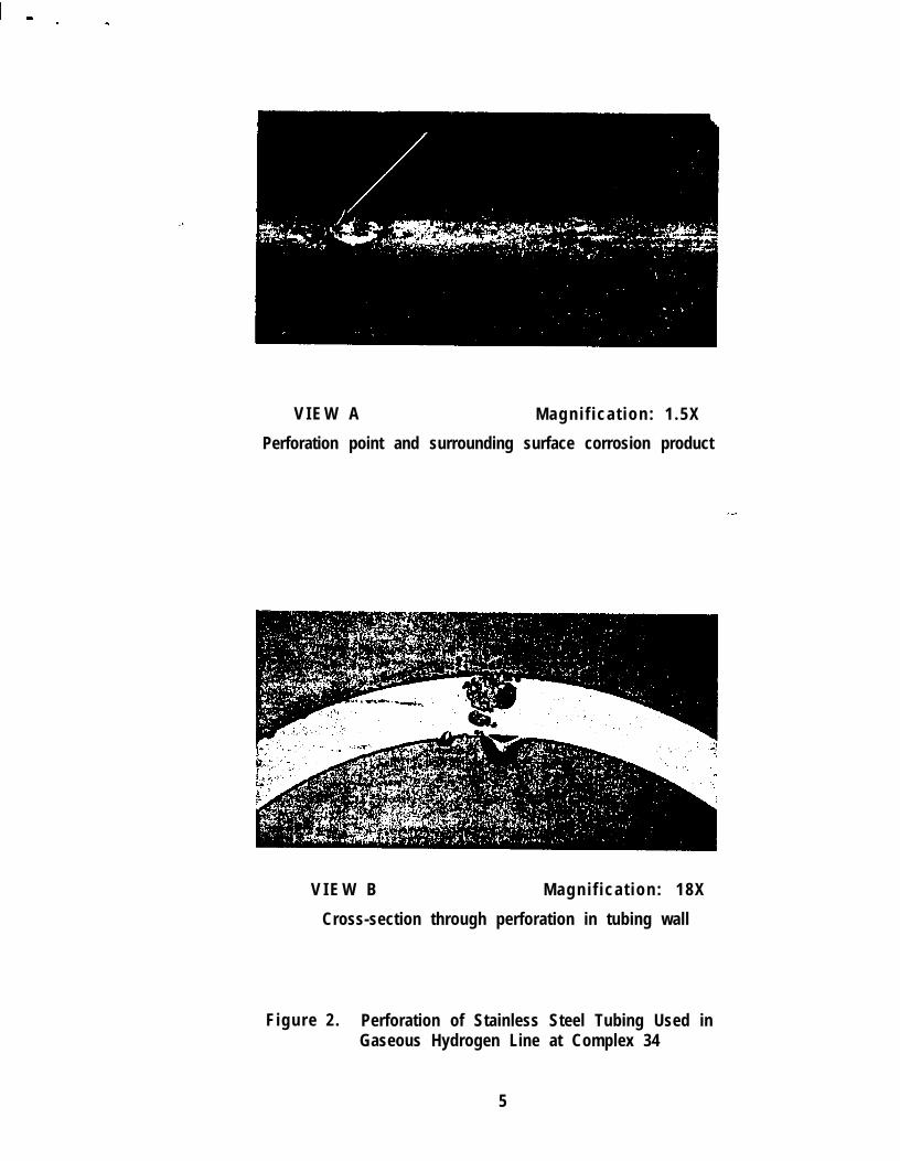
V I E W A Magni f icat ion: 1 .5X
Perforation point and surrounding surface corrosion product
V I E W B Magni f icat ion: 18X
Cross-section through perforation in tubing wall
Figure 2. Perforation of Stainless Steel Tubing Used inGaseous Hydrogen Line at Complex 34
5

I -
Magni f icat ion: 4X
Sleeve full-length stress corrosion crack
Figure 3. Cracked B-Nut Sleeve From Control Console Line,Mobile Launcher Service Arm 8, Complex 39
. . i
2.0 M A T E R I A L S A N D P R O C E D U R E S_
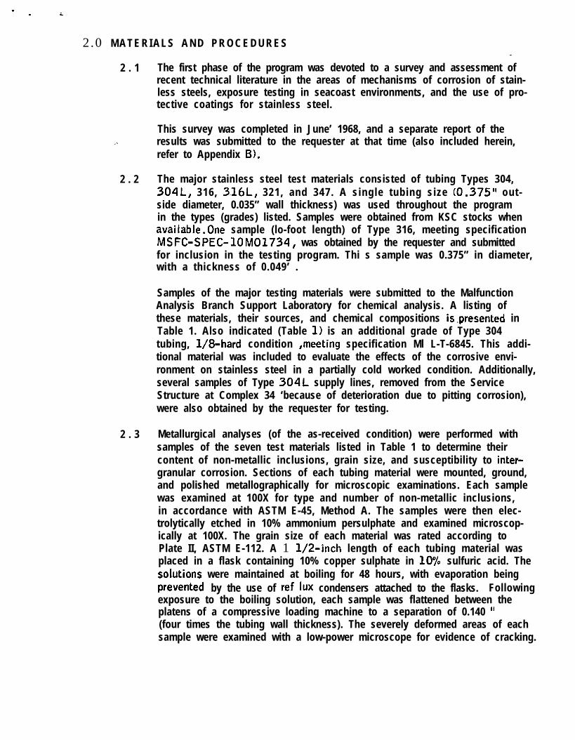
2 . 1 The first phase of the program was devoted to a survey and assessment ofrecent technical literature in the areas of mechanisms of corrosion of stain-less steels, exposure testing in seacoast environments, and the use of pro-tective coatings for stainless steel.
This survey was completed in June’ 1968, and a separate report of theresults was submitted to the requester at that time (also included herein,refer to Appendix B).
2 . 2 The major stainless steel test materials consisted of tubing Types 304,304L, 316, 3.16L, 321, and 347. A single tubing size (0.375” out-side diameter, 0.035” wall thickness) was used throughout the programin the types (grades) listed. Samples were obtained from KSC stocks whenavailable.One sample (lo-foot length) of Type 316, meeting specificationMSFC-SPEC-lOM01734, was obtained by the requester and submittedfor inclusion in the testing program. Thi s sample was 0.375” in diameter,with a thickness of 0.049’ .
Samples of the major testing materials were submitted to the MalfunctionAnalysis Branch Support Laboratory for chemical analysis. A listing ofthese materials, their sources, and chemical compositions is,presented inTable 1. Also indicated (Table 1) is an additional grade of Type 304tubing, l/8-hard condition ,meeting specification Ml L-T-6845. This addi-tional material was included to evaluate the effects of the corrosive envi-ronment on stainless steel in a partially cold worked condition. Additionally,several samples of Type 304L supply lines, removed from the ServiceStructure at Complex 34 ‘because of deterioration due to pitting corrosion),were also obtained by the requester for testing.
2 . 3 Metallurgical analyses (of the as-received condition) were performed withsamples of the seven test materials listed in Table 1 to determine theircontent of non-metallic inclusions, grain size, and susceptibility to inter-granular corrosion. Sections of each tubing material were mounted, ground,and polished metallographically for microscopic examinations. Each samplewas examined at 100X for type and number of non-metallic inclusions,in accordance with ASTM E-45, Method A. The samples were then elec-trolytically etched in 10% ammonium persulphate and examined microscop-ically at 100X. The grain size of each material was rated according toPlate II, ASTM E-112. A 1 l/2-inch length of each tubing material wasplaced in a flask containing 10% copper sulphate in 10% sulfuric acid. ThesoJutions were maintained at boiling for 48 hours, with evaporation beingprevented by the use of ref lux condensers attached to the flasks. Followingexposure to the boiling solution, each sample was flattened between theplatens of a compressive loading machine to a separation of 0.140 Ii(four times the tubing wall thickness). The severely deformed areas of eachsample were examined with a low-power microscope for evidence of cracking.

Table 1. Identification of Major Sample Materials
Alloy Applicable Chemical Composition, Percent of ElementsType Condit ion Specification Source Carbon Manganese S i I icon Sulfur Chromium Nickel Remarks
3 0 4 A n n e a l e d M I L - T - 8 5 0 4 K S C S t o c k s 0.057 1.20 0.71 0.017 17.98 9.20 -
3 0 4 l/8-hard M I L - T - 6 8 4 5 K S C S t o c k s 0.049 1.81 0.77 0.009 17.51 9.77 -
304L Annealed A S T M - A 2 6 9 Direct pur- 0.030 1.81 0.66 0.010 18.58 9.97 -chase, vendor
3 1 6 A n n e a l e d A S T M - A 2 6 9 K S C S t o c k s 0.059 1.87 0.41 0.016 16.73 12.00 Note1
03 3 1 6 L Annealed A S T M - A 2 6 9 Direct pur- 0.025 2.10 0.44 0.015 16.71 12.50 Note2chase, vendor
3 2 1 A n n e a l e d M I L - T - 8 6 0 6 6 K S C S t o c k s 0.047 1.65 0.68 0.010 17.42 10.97 Note3
3 4 7 Annealed A S T M - A 2 6 9 Direct pur- 0.065 1.79 0.73 0.005 19.96 10.64 N o t e 4chase vendor
Note 1 - Molybdenum 2.19Note 2 - Molybdenum 2.30Note 3 - Ti tan ium 0 .42Note 4 - Niobium 0.28
,
i / (

2 . 4 The basic exposure test specimens consisted of five-foot lengths of tubing,mounted horizontally in a support rack. The tube ends were closed withplastic caps (Caplugs) to prevent introduction of corrodents to the inner sur-faces. For special tests involving internally pressurized samples, severalfive-foot sections of Types 304, 304 l/8-hard, and 316 were preparedwith flared ends for the attachmentvof AN fittings.
Several smaller tubing assemblies, consisting of Type 304, back-to-backs,approximately 12 inches long, were prepared with various flare fittingsattached. The samples were used in the evaluation of protective coatings attubing junction areas.
2 . 5 The coatings evaluated consisted mainly of zinc-rich paints, and a specialproprietary aluminum-filled material. A single vendor’s material was selectedfor testing each category of the coatings, since it was the purpose here toevaluate types of materials (rather than to qualify many materials of a giventype). The following coating materials were applied:
Koppers Organic Zinc PaintCarbo Zinc-11 Inorganic Zinc Paint (Carboline Company)01390AR-3 (Zinc Modified)0 1390AR-7 (Goodrich) . _.
The latter two materials (AR-3 and AR-71 are proprietary coating materials,not yet commercially marketed, containing aluminum powder. Their conceptwas developed by the KSC Materials Testing Branch (MTB), and the testmaterials were formulated by Goodrich. MTB modified the AR-3 by theaddition of zinc powder. The AR-7 was applied to the samples withoutmodification of the coating.
A self-sealing polyethylene tape was also evaluated, to a limited extent,being applied to some tubing assemblies with attached fittings.
2 . 6 The standard surface preparation for the tubing sampIes, prior to the appli -cation of the organic-base coatings, consisted of solvent cleaning withacetone followed by phosphoric acid wash (specification MIL-M-10578,Type II). Surface preparation for appli cation of the inorganic-base zinc-rich paint consisted of abrasive blasting with 20/30-mesh silica sand.
Passivation with 20% nitric acid or 20% nitric acid with 2% sodium dichro-mate was applied to several tubes that were then exposed without furthertreatment.
One sample of Type 304 tubing, that had been electropolished, was sub-mitted for testing by the requester.
9

2 . 7 Application of the zinc-rich coatings was effected by conventional spray -equipment, in accordance with the manufacturer’s recommendations. Thesame general application procedure was used for the aluminun+rich material, ,the 013%AR-7 containing 40Wt. “/ Al powder, and the zinc modifiedcoating (013%AR-3 Zn, containing 30 Wt .% Al powder and 40 Wt. “/o Znpowder). All these coatings were applied to a nominal dry film thickness of4 mils. Coating thickness was determined by measuring with a micrometer.On each of the coated samples, deliberate defects in the cqatings wereintroduced by scribing Xs through them to the bare metal.
Organic zinc-rich paint was brush applied to several samples of the “used”material from Complex 34. Surface preparation of these samples, prior toapplication of the paint, consisted of solvent wiping only <direct applicationof paint after wiping lightly with an acetone-dipped cloth), and of solventwiping followed by the phosphoric acid wash.
2 . 8 The test samples were installed in support racks, located on the beach nearthe tip of Cape Kennedy approximately 300 feet from the high-tide line.The racks provided for horizontal mounting of the samples with half the tubelength sheltered from direct rain impingement by a cover. The other half ofthe tube length projected from the shelter and was completely exposed to theelements. One of the racks was adapted for internal pressurizatio.n of severaltubing samples. These samples had one end closed with plugs, and the otherend manifolded to a GN2 supply at nominally 2,000 psi. This internalpressure resulted in a hoop stress of about 10,000 psi. The racks werepositioned at the test s’ite such that the tube length was oriented in a north-south direction. An illustration of one such test rack, with tubing samplesinstalled, is shown in Figure 4. The tubing samples were secured to therack support bars by means of stainless steel Adel Clamps with polytetra-fluoroethylene cushions.
2 . 9 Tubing samples were installed in Test Racks (No. 1, 3, and 4) at the testsite, and a tabulation of the samples is presented in Table 2.
2 . 1 0
-.
Evaluation of the exposure-test samples consisted of regular visual inspec-tions of both the bare and coated samples. Periodically, photographs weremade for documentation, and metallurgical analyses were performed onseveral samples (removed from the exposure racks). From thevisual inspec-tions, the first evidence of pitting initiation on the bare samples was noted,and adhesion and sacrificial protection on the coated samples were evalu-ated. After an exposure period of six to seven months, four tubing samples(No. 7, 8, 9, and 10 in Test Rack 3) were removed and brought to thelaboratory for examination. Following the laboratory examination, thesamples were returned to the beach test site for continued exposure. Aftera total exposure of approximately 28 months, these same samples, togetherwith samples 4,5,6, and 37, were removed (from Test Rack 3) for completemetallurgical examination. Two tubing-assembly samples (34 and 37, fromTest Rack 4) were removed for metallurgical analysis after an exposure -J
1 0

,*
period of 12 to 14 months. One of these assemblies was bare, and the otherhad been sandblasted and coated with inorganic zinc paint. A comparativeevaluation of these assemblies was performed. The tubing samples werephotographed to show typical areas of pitting corrosion, and these areaswere then examined extensively with a low-power microscope. The deeperpits were identified by this method of surface inspection. Portions of thesample tubes containing the deep pits were prepared metallographically formicroscopic examination. The pit areas were polished as cross sections andwere examined microscopically at intervals during the polishing process, sothat the deepest penetration of the pits in the tubing wall was determined.Photomicrographs of the microsections were obtained to show pit depth.
1 1

Figure 4. Corrosion Test Rack Number 3 With Tubing Samples at Cape Kennedy Beach Test Site
.
/t --.----- -.. . -- ._-.---. -..-- ---.___. _....
i .._. -- -.---.._.- --- --._ _...- _..-.-.--- ------._ ..-..---- - ---_. -... ---.-_ ____ .._

I . - . -
Table 2. Loy of Tubing Samples in Corrosion Test Racks
SamplePosition
1
2
3
4
5
. 6
7
8
9
1 0
1 1
1 2
1 3
1 4
1 5
1 6
1 7
1 8
1 9
2 0
2 1
2 2
2 3
Alloy <SurfaceType Preparation
3 2 1 Passivated, 2070 HN03
304L Passivated, 20’5 HN03
3 0 4 l/8-hard Passivated,‘ 20% HN03
3 1 6 L Solvent cleaned
304L Solvent cleaned
3 4 7 Solvent cleaned
3 0 4 l/8-hard Solvent cleaned
3 1 6 Solvent cleaned
3 2 1 Solvent cleaned
3 0 4 Solvent cleaned
3 0 4 Abrasive blasted
304 L Removed Solvent wiped, MIL-from Complex 34 M - 1 0 5 7 8 , T y p e I I
304 L Removed Solvent wiped, MIL-from Complex 34 M - 1 0 5 7 8 , T y p e I I
304 L Removed Solvent wiped, MIL-from Complex 34 M - 1 0 5 7 8 , T y p e I I
304 L Removed Solvent wiped, MIL-from Complex 34 M - 1 0 5 7 8 , T y p e I I
3 1 6 L Solvent cleaned
3 0 4 L Solvent cleaned
3 4 7 Solvent cleaned
3 0 4 i/8-hard Solvent cleaned
3 1 6 Solvent cleaned
3 2 1 Solvent cleaned
3 0 4 Solvent cleaned
3 0 4 Abrasive blasted
TEST RACK NO. 3
1 3
Coating
None
None
None
None
None
None
None
None ’
None
None
inorganic Zinc
Organic Zinc
May 20,1968
M a y 2 0 , 1 9 6 8
May 20,1968
IApri
Apri I
Apri
Apri
2 2 , 1 9 6 8
22,1968
11,1968
22,1968
A p r i l 1 1 , 1 9 6 8
Aprilall, 1 9 6 8
A p r i l 1 1 , 1 9 6 8
A p r i l 2 5 , 1 9 6 8
A p r i l 3 0 , 1 9 6 8
Organic Zinc A p r i l 3 0 , 1 9 6 8
Organic Zinc A p r i l 3 0 , 1 9 6 8
Organic Zinc A p r i l 3 0 , 1 9 6 8
None April 2 2 , 1 9 6 8
None April 2 2 , 1 9 6 8
None April 1 1 , 1 9 6 8
None April 2 2 , 1 9 6 8
None April 1 1 , 1 9 6 8
None April 1 1 , 1 9 6 8
None April 1 1 , 1 9 6 8
Inorganic Zinc April 2 5 , 1 9 6 8
DateInstalled

Table 2. Log of Tubing Samples in Corrosion Test Racks (Continued)
S a m p l e ‘- AlloyPosition T y p e
2 4 3 1 6
2 5 3 4 7
2 6 3 1 6 L
2 7 3 0 4
2 8 3 1 6
2 9 3 0 4
3 0 3 0 4
3 1
3 2
3 3
3 4
3 5
3 6
3 7
3 0 4
3 0 4
3 0 4
3 0 4
3 0 4
3 1 6 (MSFClOMO1734)
3 1 6 (MSFClOMO1734)
4 3 0 4
5 3 1 6
TEST RACK NO. 3 (Continued)
SurfacePreparation
Passivated, 20% HN03
Passivated, 20% HN03
Passivated, 20% HN03
Passivated, 20% HN03
M I L - M - 1 0 5 7 8(6 month in terva ls )
M I L - M - 1 0 5 7 8(6 month intervals)
M I L - M - 1 0 5 7 8(1 month intervals)
M I L - M - 1 0 5 7 8(12 month intervals)
M I L - M - 1 0 5 7 8
M I L - M - 1 0 5 7 8
M I L - M - 1 0 5 7 8
M I L - M - 1 0 5 7 8
MIL-M-15078
Solvent cleaned None A p r i l 2 5 , 1 9 6 8
TEST RACK NO. 4
Coating
None
None
None
N o n e
None
None A p r i l 2 5 , 1 9 6 8
None April 25,1968
None A p r i l 2 5 , 1 9 6 8
Organic Zinc A p r i l 2 5 , 1 9 6 8
Organic Zinc A p r i l 2 5 , 1 9 6 8
Organic Zinc A p r i l 2 5 , 1 9 6 8
Organic Zinc A p r i l 2 5 , 1 9 6 8
None A p r i l 2 5 , 1 9 6 8
Electropol ished
Passivated in 2070Nitric Acid - F/O SodiumDichromate
None
None
DateInstalled
May 20,1968
May 20,1968
May 20,1968
May 20,1968
A p r i l 2 5 , 1 9 6 8
-’
1 4

Table 2. Log of Tubing Samples in Corrosion Test Racks (Continued)
Sample AlloyPosition T y p e
6 3 0 4
7 3 0 4
8 3 1 6
9 3 0 4
1 0 3 0 4
2 4 3 0 4
2 5 3 0 4
2 6 3 0 4
2 7 3 0 4
2 8 3 1 6
2 9 3 1 6
3 0 3 0 4
3 1 3 0 4
3 2 3 0 4
TEST RACK NO. 4 (Continued)
SurfacePreparation
Passivated in 2070Nitric Acid - P/O SodiumDichromate
Passivated in 20%Nitric Acid - 2% SodiumDichromate
Passivated in 2070Nitric Acid - 2% SodiumDichromate
Abrasive blasted
Abrasive blasted plusM I L - M - 1 0 5 7 8
M I L - M - 1 0 5 7 8
M I L - M - 1 0 5 7 8
Abrasive blasted
Abrasive blasted plusM I L - M - 1 0 5 7 8
M I L - M - 1 0 5 7 8
M I L - M - 1 0 5 7 8
Solvent cleaned
Solvent cleaned
Solvent cleaned
Coatina
None
None
None
Inorganic Zinc 14 August 1969
Inorganic Zinc 1’4 August 1969
Organic Zinc
Organic Zinc
Organic Zinc
Organic Zinc
Organic Zinc
Organic Zinc
0139-AR3-Zn
0139-AR7
0139-AR7
23 January1 9 7 0
23 January1 9 7 0
23 January1 9 7 0
23 January1 9 7 0
23 January1 9 7 0
23 January1 9 7 0
23 January1 9 7 0
23 January1 9 7 0
23 January1 9 7 0
DateInstalled
1 5
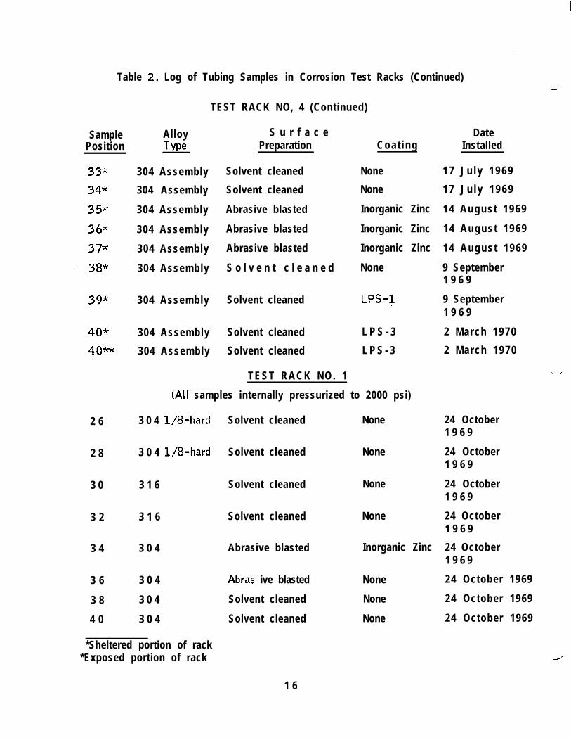
Table 2. Log of Tubing Samples in Corrosion Test Racks (Continued)
SamplePosition
33%
34*
35*
36*
37*
- 38*
39*
Alloy S u r f a c eType Preparation Coat ing
304 Assembly Solvent cleaned None
304 Assembly Solvent cleaned None
304 Assembly Abrasive blasted Inorganic Zinc
304 Assembly Abrasive blasted Inorganic Zinc
304 Assembly Abrasive blasted Inorganic Zinc
304 Assembly S o l v e n t c l e a n e d None
304 Assembly Solvent cleaned LPS-1
40* 304 Assembly Solvent cleaned L P S - 3
40* 304 Assembly Solvent cleaned L P S - 3
TEST RACK NO. 1
(All samples internally pressurized to 2000 psi)
2 6 3 0 4 l/8-hard
3 0 4 l/8-hard
3 1 6
Solvent cleaned None
2 8 Solvent cleaned None
3 0 Solvent cleaned None
3 2 3 1 6 Solvent cleaned None
3 4
3 6
3 8
4 0
3 0 4
3 0 4
3 0 4
3 0 4
Abrasive blasted Inorganic Zinc
Abras ive blasted None
Solvent cleaned None
Solvent cleaned None
-
TEST RACK NO, 4 (Continued)
DateInstalled
1 7 J u l y 1 9 6 9
1 7 J u l y 1 9 6 9
14 August 1969
14 August 1969
14 August 1969
9 September1 9 6 9
9 September1 9 6 9
2 March 1970
2 March 1970
24 October1 9 6 9
24 October1 9 6 9
24 October1 9 6 9
24 October1 9 6 9
24 October1 9 6 9
24 October 1969
24 October 1969
24 October 1969
*Sheltered portion of rack*Exposed portion of rack
1 6

3 . O R E S U L T S
3 . 1 Metallurgical Analyses of Initial Materials
This section contains the results of various tests performed on the tubingmaterials in the “as received” condition (described in paragraph 2.3).
3 . 1 . 1 Intergranular Embrittlement. Microscopic examination of thesamples exposed to the boiling copper sulphate and then flattenedrevealed no evidence of surface cracking associated with inter-granular attack in any of the test materials, Some very smallsurface cracks, not associated with grain boundaries, were de-tected in the Type 32 1 samples. It is believed that these surfacedefects were caused by localized attack of the copper sulphatesolution at non-metallic inclusions in the Type 321 tubing surface.
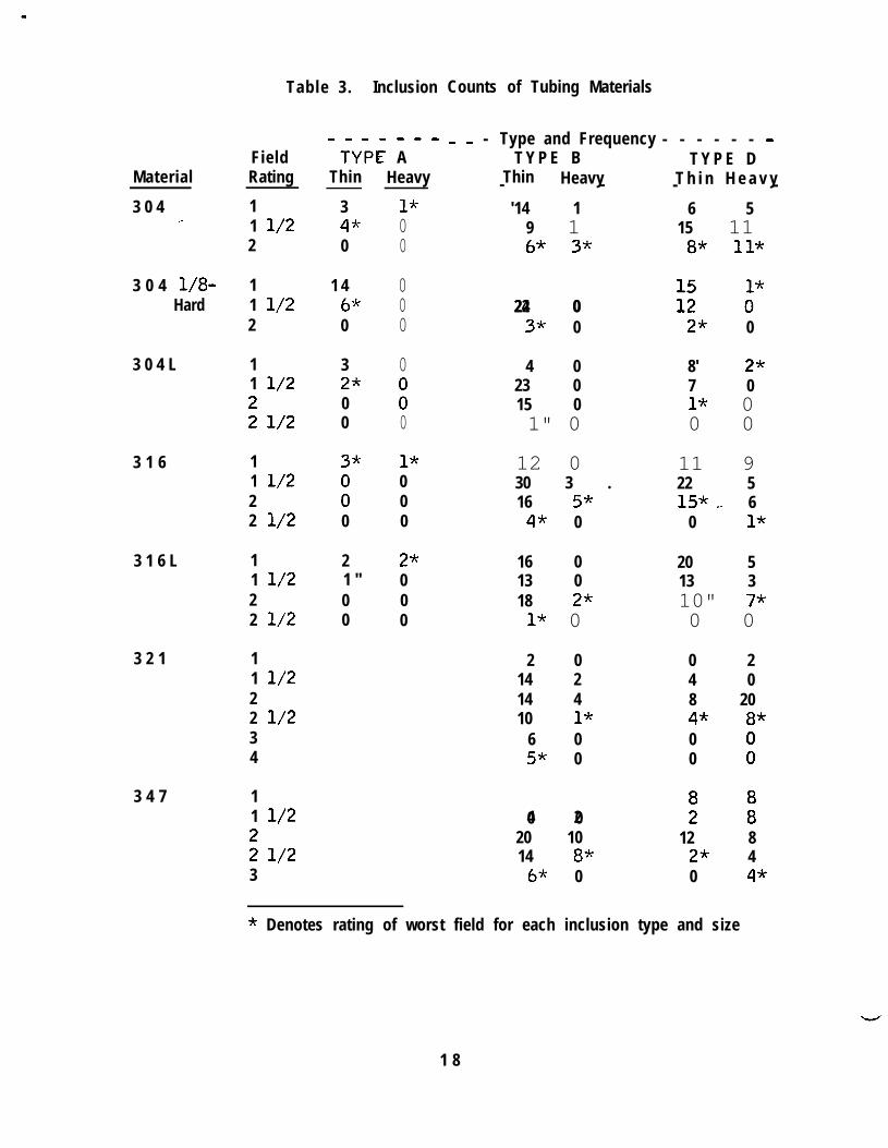
3 . 1 . 2 Non-Metallic Inclusions. The results of the inclusion countsin terms of the frequency {number of fields) of each inlusion type,size, field rating, and the worst field of each type are listed inTable 3. These ratings indicate the sample materials to be ofnormal “cleanliness” for air-melted stainless steels. The oxidecontent OF Types 321 and 347 was considerabj? higher than thatof the other materials, and this probably results from oxidation ofsome of the reactive-metal additives (titanium, niobium, and tan-talum) used for carbide stabilization in these grades.
3 . 1 . 3 G r a i n S i z e . The results of the grain size determinations are pre-sented in Table 4. All of the test materials had a grain size of 7or smaller, except Type 304L, which was rated 6 l/2. Size 7or smaller is considered desirable in stainless steel tubing materials.
3 . 2 Visual Inspection of Exposure Samples
3 . 2 . 1 Visual inspections of the samples were made at frequent intervals,particularly in the early stages of the exposure tests. It was foundthat all of the bare tubing samples, solvent cleaned (only) prior toexposure, developed corrosion sites within 11 days of exposure.
The sample of Type 304 that had been electropolished (RackNumber 4, Sample 4) showed corrosion initiation after 21 daysof exposure. Corrosion initiated on the passivated samples (RackNumber 4, Samples 5 through 8) after 30 days of exposure.Periodic cleaning with the phosphoric acid wash (MIL-M-10578,Type II) was apparently beneficial if applied at monthly intervals,at least on the basis of superficial inspection. Closer inspectionwith a hand lens revealed that extensive pitting had occurred onthe cleaned sample, and suggested that the main benefit wascosmetic (removal of corrosion products that otherwise tended tocollect on the less frequently cleaned (or not cleaned) sample).
1 7
Material
3 0 4,-
3 0 4 l/8-Hard
3 0 4 L
3 1 6
3 1 6 L
3 2 1
3 4 7
Table 3. Inclusion Counts of Tubing Materials
FieldRating
11 l/22
11 l/22
11 l/2
s l/2
11 l/222 l/2
11 l/222 l/2
11 l/222 l/234
11 l/2
z l/23
---w---
TYPIE AThin Heavy
3 1*43' 00 0
1 46%0
32*00
33'
i0
21 "00
000
0
:0
1*000
2*000
0 0 - Type and Frequency - - - - - - -T Y P E B T Y P E D
Thin Heavy T h i n H e a v y- - - -'14 1 6 5
9 1 15 1163' 331 8* ll*
24 022 0 tz 0'"3-k 0 2* 0
4 0 8' 2*23 0 7 015 0 1* 01" 0 0 0
12 0 11 930 3 . 22 516 5* 153;~. 64* 0 0 1*
16 0 20 513 0 13 318 2-k 10" 73'1* 0 0 0
2 0 0 214 2 4 014 4 8 2010 1* 4* 8*
6 0 05* 0 0 i
0 04 2 ii i20 10 12 814 83' 2* 4
63' 0 0 4*
* Denotes rating of worst field for each inclusion type and size
1 8
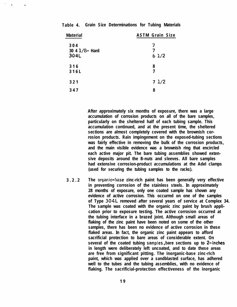
Table 4. Grain Size Determinations for Tubing Materials
Material ASTM Gra in S ize
3 0 430 4 l/8- Hard304L
3 1 6 83 1 6 L 7
3 2 1 7 l/2
3 4 7 8
After approximately six months of exposure, there was a largeaccumulation of corrosion products on all of the bare samples,particularly on the sheltered half of each tubing sample. Thisaccumulation continued, and at the present time, the shelteredsections are almost completely covered with the brownish cor-rosion products. Rain impingement on the exposed-tubing sectionswas fairly effective in removing the bulk of the corrosion products,and the main visible evidence was a brownish ring that encircledeach active major pit. The bare tubing assemblies showed exten-sive deposits around the B-nuts and sleeves. All bare sampleshad extensive corrosion-product accumulations at the Adel clamps(used for securing the tubing samples to the racks).
3 . 2 . 2 The organic-Sase zinc-rich paint has been generally very effectivein preventing corrosion of the stainless steels. In approximately28 months of exposure, only one coated sample has shown anyevidence of active corrosion. This occurred on one of the samplesof Type 304L removed after several years of service at Complex 34.The sample was coated with the organic zinc paint by brush appli-cation prior to exposure testing. The active corrosion occurred atthe tubing interface in a brazed joint. Although small areas offlaking of the zinc paint have been noted on some of the othersamples, there has been no evidence of active corrosion in theseflaked areas. In fact, the organic zinc paint appears to affordsacrificial protection to bare areas of considerable extent. Onseveral of the coated tubing samples,bare sections up to 2-inchesin length were deliberately left uncoated, and to date these areasare free from significant pitting. The inorganic-base zinc-richpaint, which was applied over a sandblasted surface, has adheredwell to the tubes and the tubing assemblies, with no evidence offlaking. The sacrificial-protection effectiveness of the inorganic
1 9
zinc is also excellent. One tubing assembly was deliberatelyleft with an uncoated strip (approximately 3/16” wide, and -extending the entire length of the assembly). There has beenno evidence of corrosion on this exposed, sandblasted stain- -less steel surface. The aluminum-rich and aluminum-zinc-richproprietary coatings have adhered completely, and have evidentlyweathered well. No corrosion of the stainless steel substrate hasoccurre’d, and there is no evidence of deterioration of these coat-ings.
The general appearance of several of the coated and bare test spec-imens in Racks Number 3 and 4 is shown in Figures 5 through 11.Figures 5 and 6 show the underside of a group of bare and coatedtubing samples in the sheltered section of Rack Number 3 afterapproximately three months exposure. The four coated samples inFigure 5 are the tubes removed from Complex 34 and brush coatedwith organic zinc paint. Two of the tubes also have short sectionswrapped with self-sealing polyethylene tape. Note that three of thecoated tubes have bare spots near the end caps. These bare spotshave not shown active corrosion during the total exposure periodof approximately 30 months; evidently because of sacrificial pro-tection afforded by the zinc coating. The dark spots on the baretubes are accumulations of corrosion products around active pits.
Similar conditions are shown on the bare samples illustrated inFigure 6. The single coated sample at the bottom of the photograph ._has the inorganic zinc paint applied over a sandblasted surface.This coating has remained intact after 30 months exposure.
Figures 7 and 8 show other bare and organic-zinc coated tubesin the exposed and sheltered sections, respectively, of RackNumber 3 after approximately 30 months exposure. The coatingwas applied to “new” tubing samples that had been cleaned withthe phosphoric acid wash. These samples, including intentionalbare areas (or tape wrapped areas), near the end caps, haveremained essentially free of corrosion during this exposure period.
Figures 9 and 10 show coated tubing samples in exposed andsheltered sections of Rack Number 4 after 10 months of exposure.The three samples at the left side of Figure 9 were coated withthe AR-7 (or zinc modified AR-31 material. The other six samples(shown in Figure 9) were coated with organic zinc paint, aftervarious surface preparations. In Figure 10 (the sheltered portionof this same sample group), one of the AR-7 samples is not shown.The two samples at the left side (Figure 10) are the AR-7 and thezinc-modified AR-3 (the latter being the darker grey coating).
2 0

3 . 2 . 3
These coatings have remained entirely intact and protective to-thestainless steel substrate during the 10 months of exposure. Slightflaking of the organic zinc paint has occurred on the sheltered sideof two of the samples, at the X-shaped scribe marks in the coatings.However, the organic zinc coating has continued to protect the sub-strate in these areas. *
Figure 11 shows two tubing assemblies removed from the shelteredsection of Rack Number 4. The sample on the left side has beensandblasted and coated with inorganic zinc paint, and was exposedat the corrosion test site for 12 months. The bare sample wasexposed for 14 months. The B-nuts and end plugs were removed,exposing the flared ends of both samples. The zinc coated sampleshowed no evidence of corrosion. The bare sample had undergoneconsiderable crevice corrosion in the B-nut area, and there werelarge corrosion deposits under both the &nut and sleeve. Severallongitudinal cracks were noted in the sleeve. The extent of thestress-corrosion cracking, in this B-nut sleeve is described in moredetail in subsequent paragraphs herein. It is evident that the zinccoating affords protection against crevice corrosion and stress-corrosion cracking in the area of tubing attachments :s
The group of internally pressurized samples in Rack Number 1 have beenexposed approximately 14 months. Only one of these samples wascoated (inorganic zinc paint over a sandblasted surface), and itshows no evidence of corrosion or coating deterioration. The baresamples (Types 304, 304 1/8=hard, and 316) all show extensivepitting and a large accumulation of corrosion products on the shel-tered halves, as did the unpressurized samples in an equivalentexposure. period. No complete penetrations of any of the sampleshave occurred to date. The system is self-inspecting, since eachsample is provided with a separate pressure gage. Perforation ofthe tubing wa II by pitting will be indicated by a loss of pressure.
2 1

n n
\_ . .- . ..--_-..L--
.
--... ---I *_,.*,. ^ . -..ri....-dm~-.. . .I
__~ ‘,.. ,
I
I . ,.++J,. ‘**l., >’ 1 . ..*. ., ‘.‘,Y...,“,‘,
Figure 5. Tubing Samples in Sheltered Section of Rack Number 3 After 3-Months Exposure(The Four Organic-Zinc Coated Samples are Shown at Bottom>
2 2

--i;-.c: - . .I’,
v :-;. . . .A.; : ‘. I . .._‘-^. -,z.- -__. ,?,,> ,’ ., .a.:b-- “y 1: .::*
_: &.... ,_... . , -.
:-:.‘,:
Figure 6. Tubing Samples in Sheltered Section of Rack Number 3 After 3-Months Exposure(The Inorganic-Zinc Coated Sample is Shown at Bottom)
2 3

Figure 7. Bare and Organic-Zinc Coated Samples in Exposed Section of Rack Number 3(After Approximately 30-Months Exposure)
2 4

. .
Figure 8. Bare and Organic-Zinc Coated Samples in Sheltered Section of Rack Number 3(After Approximately 30-Months Exposure)
2 5
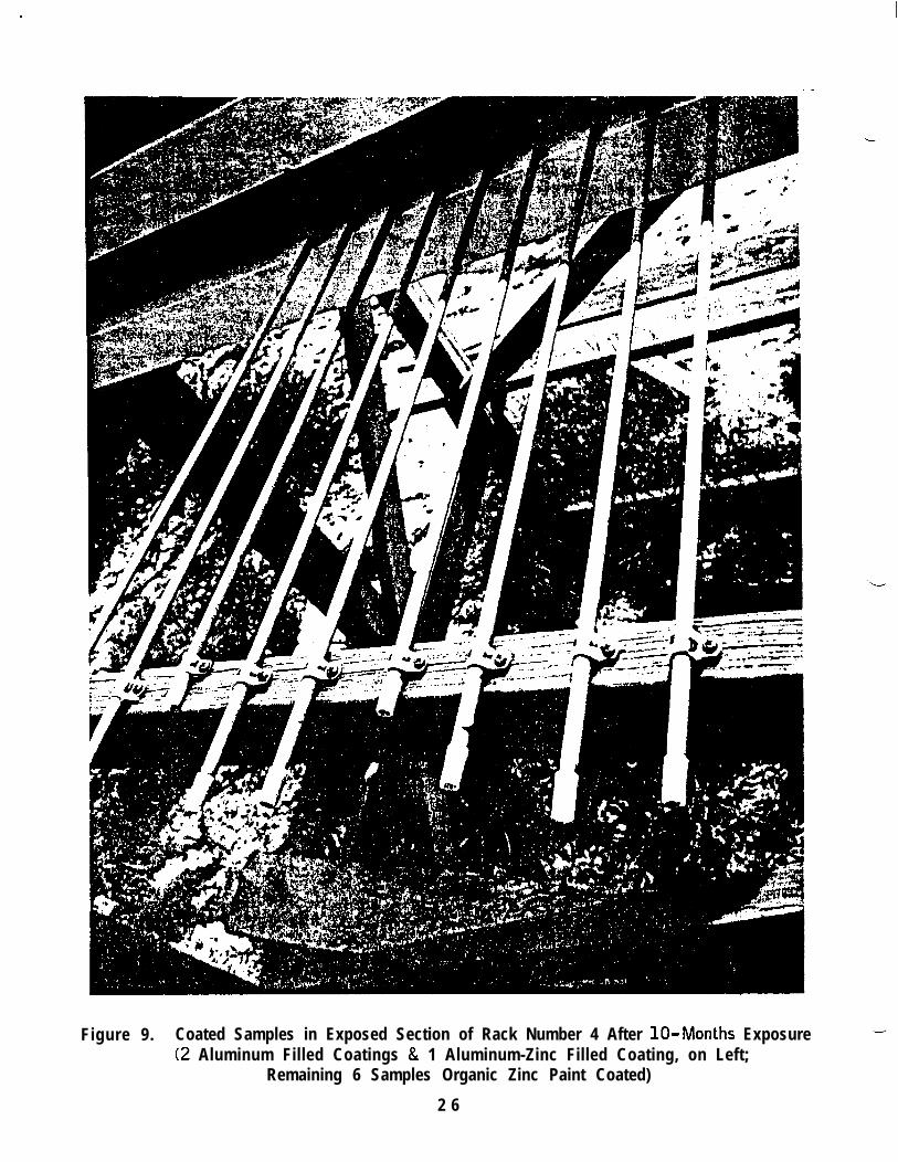
Figure 9. Coated Samples in Exposed Section of Rack Number 4 After lo-Months Exposure(2 Aluminum Filled Coatings & 1 Aluminum-Zinc Filled Coating, on Left;
Remaining 6 Samples Organic Zinc Paint Coated)
2 6
.I
-!’
*,
,.:
_1
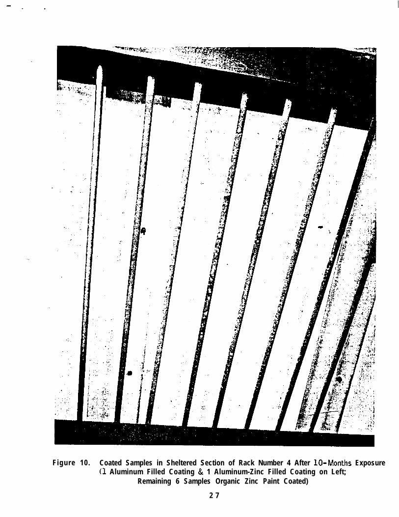
Figure 10. Coated Samples in Sheltered Section of Rack Number 4 After lo-Months Exposure(1 Aluminum Filled Coating & 1 Aluminum-Zinc Filled Coating on Left;
Remaining 6 Samples Organic Zinc Paint Coated)
2 7

--
Figure 11. Coated & Bare Tubing Assemblies After 12 and 14 Months Exposure ,--
Respectively, in the Sheltered Section of Rack Number 4(Inorganic Zinc-Rich Paint Applied Over Sandblasted Surface)
2 8
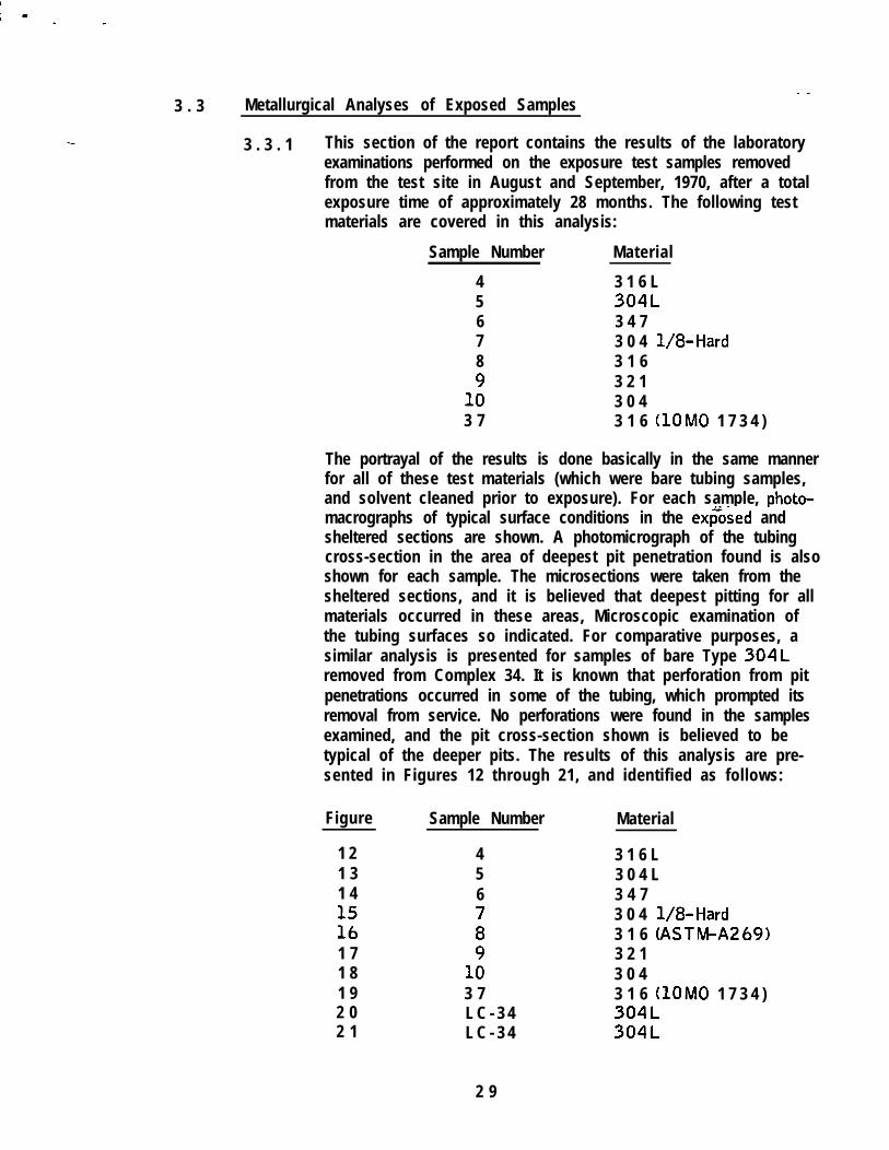
- _3 . 3 Metallurgical Analyses of Exposed Samples
3 . 3 . 1 This section of the report contains the results of the laboratoryexaminations performed on the exposure test samples removedfrom the test site in August and September, 1970, after a totalexposure time of approximately 28 months. The following testmaterials are covered in this analysis:
Sample Number
45678
1;3 7
Material
3 1 6 L304L3 4 73 0 4 l/a-Hard3 1 63 2 13 0 43 1 6 (lOM0 1 7 3 4 )
The portrayal of the results is done basically in the same mannerfor all of these test materials (which were bare tubing samples,and solvent cleaned prior to exposure). For each sample, photo-macrographs of typical surface conditions in the exGsed andsheltered sections are shown. A photomicrograph of the tubingcross-section in the area of deepest pit penetration found is alsoshown for each sample. The microsections were taken from thesheltered sections, and it is believed that deepest pitting for allmaterials occurred in these areas, Microscopic examination ofthe tubing surfaces so indicated. For comparative purposes, asimilar analysis is presented for samples of bare Type 304Lremoved from Complex 34. It is known that perforation from pitpenetrations occurred in some of the tubing, which prompted itsremoval from service. No perforations were found in the samplesexamined, and the pit cross-section shown is believed to betypical of the deeper pits. The results of this analysis are pre-sented in Figures 12 through 21, and identified as follows:
Figure Sample Number Material
1 21 31 4
i’b1 71 81 92 02 1
456
;
1;3 7L C - 3 4L C - 3 4
3 1 6 L3 0 4 L3 4 73 0 4 l/a-Hard3 1 6 (ASTM-A26913 2 13 0 43 1 6 (10MO 1 7 3 4 )304L304L
2 9
I -
V I E W A Magnification: 2XExposed Portion
V I E W 6 Magnification: 2XSheltered Portion
tI..-
‘Z,
.._, ). . s . .
V I E W C Magnification: 80X
Cross-Section of Tubing Wall in Deepest Pit Area
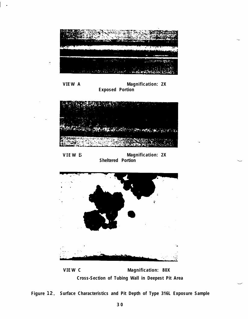
Figure 12. Surface Characteristics and Pit Depth of Type 316L Exposure Sample
3 0

.
V I E W A Magnification: 2XExposed Portion .
; .
_ . _s
).. ,:_
c,- ‘.- Ip...‘.. (. ,--
;. :‘.,
;: .._.:i.’r.:- .-.,
I
7” : ~F ,’ *.., . . .. .: : >.,I, . .
2 -*. 1 1 .:.
V I E W C Magnification: 80X
Cross-Section of Tubing Wall in Deepest Pit Area
Figure 13 . Surface. Characteristics and Pit Depth of Type 304L Exposure Sample
3 1
V I E W A Magnification: 2X
Exposed Portion
V I E W B Magnification: 2X
Sheltered Portion
‘ . . .
t. .,.
. .
.,
. .
V I E W C Magnification: 80X
Cross-Section of Tubing Wall in Deepest Pit Area
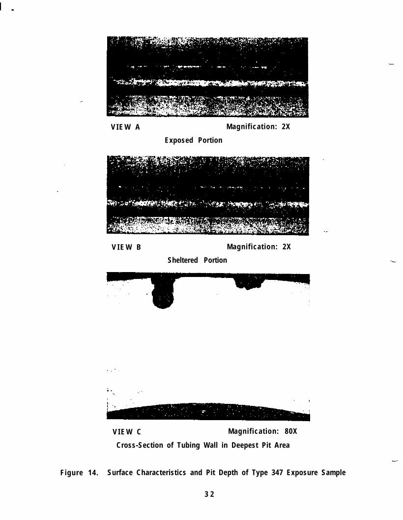
Figure 14. Surface Characteristics and Pit Depth of Type 347 Exposure Sample
3 2

! - -
V I E W A Magnification: 2X
Exposed Portion
Sheltered Portion
i.. _’ _ .
*‘.,‘..- ...’ :: . :w t
/ 1. .I ,.i1 i
‘, ,.(1 ,I,:. I,.,
I.’ ./,::I 4
c ,’ /...w, ,: ,.’
V I E W C Magnification: 80X
Cross-Section of Tubing Wall in Deepest Pit Area
Figure 15.-. Surface Characteristics and Pit Depth of Type 304 l/a-Hard Exposure Sample
3 3

-
V I E W A Magnification: 2X
Exposed Portion
V I E W B Magnification: 2X
Sheltered Portion
V I E W C Magnification: 80X
Cross-Section of Tubing Wall in Deepest Pit Area
Figure 16. Surface Characteristics and Pit Depth of Type 316 (ASTM- A2691 Exposure Sample _
3 4

V I E W A Magnification: 2X
Exposed Portion
V I E W B Magnification: 2X
Sheltered Portion
;. ‘.,
$f+, ‘1.: ., ’
g, ‘;A. ‘.
2;. . .
!, .. ,, “--,:.I,& . . li
,d ‘.“. ..:i
/’ ,““‘-‘(I. ‘.. .i. .‘.;e.-I
i”.. :,j*,, : .- . \,. 8.. .
. .~ ‘.‘.% .., . :, .1 2.‘. ‘,1 <+~, ,
. . .; ,I .,:-:
,a . . _*I’.’I _ ; . . . , , ./,.c
,“) : . I .i1, ,“‘;
V I E W C Magnification: 80X
Figure 17. Surface Characteristics and Pit Depth of Type 321 Exposure Sample
3 5

I -
V I E W A Magnification: 2X
Exposed Portion
V I E W B Magnification: 2X
Sheltered Portion
V I E W C Magnification: 80X
Cross-Section af Tubing Wall in Deepest Pit Area
Figure 18. Surface Characteristics and Pit Depth of Type 304 Exposure Sample
3 6

V I E W A Magnification: 2X
Exposed Portion
V I E W B Magnification: 2X
Sheltered Portion
” ‘., .‘? .;
.’ :,’;.&&- ..#.i.:’ ,.-‘“.
. . . ’..; ,y L”.,.\ ,f’
I ,‘,._., ““7., i,. “7
V I E W C Magnification: 55XCross-Section of Tubing Wall in Deepest Pit Area
(Tubing Wall Thickness 0.049”)
Figure 19 . Surface Characteristics and Pit Depth of Type 316 (MSFC lOMO1734)Exposure Sample. (Tubing Wall Thickness of Sample was 0.049”)
3 7

I -
V I E W A Magnification: 4X
V I E W B Magnification: 55X
Figure 20. Surface Characteristics of Pit Areas of Type 304L TubingRemaved From Complex 34
3 8

V I E W A Magnification: 80X
.-.
V I E W B Magnification: 80X
Figure 2 1. Cross-Sections Through Tubing Wall in Deepest Pit Areas,Type 304L Tubing Removed From Complex 34
3 9

3 . 3 . 2 The characteristic surface appearance of corrosion pits in aus-tenitic stainless steels can be observed in the photomacrographs --of the exposed portions of the tubing samples. The pit itselfappears as a tiny dark spot in the approximate center of a smallclear area, which is, in turn, surrounded by the usual reddish-brown deposit of corrosion products. This deposit is typicallyseen as a ring, or broad, generally circular band. These charac-teristics are usually obscured in the sheltered portion of thesample, because of the heavy accumulation of corrosion products.These heavy accumulations are prevented in the exposed portionby rain impingement.
The photomicrographs of the tubing wall cross-sections show thedepth of pitting for each material. These are believed to representthe deepest penetration existing in the test samples examined.However, because of the fortuitous nature of the pit population,and the limited techniques available for determining maximumdepth of each and every pit, an exact comparative evaluation of“pitting rate” is not possible. It is evident that the pit morpho-logy in the various test materials is basically similar, and is alsosi milar to that in the samples obtained from service”applicationsat KSC (e.g. Figures 1, 2, 20, and 2 1). There is clear evidencefrom the visual inspections that there is a much higher pit popula-tion in Types 321 and 347 than in Types 304 and 316. The
-Type 316 probably has the lowest pit population of all the gradestested. Obviously, the Type 316 does not, in contrast to apopular misconception have a lower pitting rate (rate of pit pene-tration into tubing wall) in actual service environments.
As a matter of fact, the deepest pits found to date in any of thesamples have been in Type 316L and in the Type 316 (MSFClOM0 17341, as is shown in Figures 12 and 19. This is notto suggest that Type 316 has a higher pitting rate than the othergrades; in another Type 316 sample (Figure 16), no deep pits werefound. The evidence cited here does suggest that no singleaustenitic stainless steel of the grades tested in this program issignificantly better that the others for the fluid-systems applica-tions in an environment of the KSC-type.
Further insight into pitting rate and the effects of service stressesfrom internal pressurization may be obtained from the pressurizedtest samples. It is possible that hoop stresses from internal pres-surization can accelerate the pitting rate, and, if this is the case,a trend may be evident in the evaluation of the pressurized samples,
4 0

3 . 3 . 3 The most clearly evident effect of applied stresses on the struc-tural integrity of the austenitic stainless steels in the fluid-systems applications is manifested in stress-corrosion failures,as mentioned previously. A failure of this type was discoveredin the bare tubing assembly (Figure 11) that was removed fromRack Number 4 after 140months.of exposure at the beach testsite. The B-nut sleeve had several longitudinal cracks, whichapparently initiated on the inner tapered surface that was bearingagainst the tubing flare.
Figure 22 shows a photomacrograph of this inner surface, withthe stress corrosion cracks and corrosion products, and a photo-micrograph of a longitudinal microsection cut from the sleeveand prepared metal lographically. In the photomicrograph , thebranching nature of the stress-corrosion cracks can be seen.The small “stringers” in the microstructure are iron sulfideinclusions, which are typical of the Type 303 grade. Althoughthe B-nuts and other major fittings used in the tubing assemblywere the 316 grade (Type K), the Binut sleeve (whose identitywas not disclosed by markings) was Type 303, aswas confirmedby chemical analysis. It is probable that Type 303 accounts formost of the stress-corrosion failures of tubing fittings that haveoccurred at KSC .
4 1

I -
V I E W A Magnification: 7X
Sleeve Inner Surface
,. ., ‘.*I . . sr
I ,>. . e. i,iC;.(b-
., , “5.
Li&-y-: -..:‘:’ .9;‘ +a.g. a- ‘* ~. .’:+.,f:,. L”--)
,*i;.r;-
,,; .: 2.
f -
(.:._“$f;;;”
p ‘. . <‘.
f?.?.$. .
,r
,- . _. .
a-. . v +’--.
V I E W B Magnification: 80X
Longitudinal Microsection
Figure 22. Stress-Corrosion Cracking in Type 303 B-Nut Sleeve From Bare TubingAssembly Removed From Rack Number 4 After 14-Months Exposure
4 2

4 . 0 D I S C U S S I O N
4 . 1 Pitting Corrosion
,-For amplification of the previous references to the mechanisms of pittingcorrosion, the following discussion is submitted. In pursuing thesepoints, reference is made to the attached figures, which depict schematic-ally the morphological and electrochemical conditions prevailing in thepitting corrosion of a section of stainless steel tubing. Figure 23 showsthe tubing surface in the vicinity of an active ‘pit, operating in a film ofmoisture in which there is a dissolved electrolyte. In the KSC area,this is usually sodium chloride, although various other compounds canserve as “solution-type” (ionic) conductors. Chloride ion, as pointedout by Fontana, has the apparently unique ability to penetrate the nor-mally protective complex oxide layer on the stainless steel to cause pit-ting initiation. In the absence of the chloride ion, pitting is usuallyinitiated at points where mechanical ‘breakage of the oxide layer hasoccurred or at non-metallic inclusions present at the metal surface. Pit-ting, once initiated, usually continues whenever moisture is available(whether from condensation, salt fog, or other source). The center of thesite, the pit itself, is the anode, within which are generated iron ions(ultimately Fe+tt) and hydrogen ions (H+). At some distance away fromthe pit but in the moisture film is located the cathodic site which is arelatively large area of the unbroken oxide layer on the tubing surface.With this condition, there is a large driving force for enlargement of thepit, since the limiting factor in the electrochemical current generated bythe cell is the area of the anode. The cell potential for the pitting ofstainless steel is of the order of 0.7 volt. This type of electrochemicalactivity is called an “active-passive” cell. Hydroxide ions (OH’) gener-ated in the cathodic area surrounding the pit and ferric ions (Fe+?generated in the pit migrate toward the opposite electrodes and meet in aring-shaped area around the pit. In this area, the brownish corrosionproduct, identified many times by x-ray diffraction analyses as consist-ing mainly of iron oxyhydroxide iFeOOH), is deposited on the stainless steelsurface. Figure 24 shows the same basic pitting mechanism occurringin a cross-sectional view of the tubing wall. Note that hydrogen ionstend to accumulate within the pit itself, so that the pH may commonly beof the order of 1. The significance of this point has been re-emphasizedrecently in a technical note authored by B. F. Brown of the U.S. NavalResearch Laboratory .1 Brown notes the basic similarity of several formsof localized attack - stress-corrosion cracking, pitting, intergranularcorrosion, crevice corrosion, etc. - with respect to the acid condition atthe site of the corrosion attack. The acid is formed by hydrolysis of the
1. B. F. Brown, “Technical Note: Concept of the Occluded Corrosion Cell,”Corrosion, Vol . 2 6 , No. 8 , August 1 9 7 0 , pp. 2 4 9 , 2 5 0 .
4 3

r Pit (Anode; source of Fe+++)
Surrounding RustDeposit (Source of OH ‘)
Brownish bond deposit of FeOOH
Figure 23. Surface of Tubing in Pit Area ’
/-
Acid, decreasing inconcentration owoy from pit
r Tubing Wall Cathode
OH - ianc Fei-i-i
-.. .-..- / OH - ions ~-Hz0 ondu PI
decipitote 1Anode, pit containing Hz0 with high concentration of H”ions
ofUrFeOOH(about pH 1). with outword migrating Fe”-+’ ions. Note: FeC13con form from sol+ contominotion and is stable ot this pH,contributing to further pitting.
Figure 24. Longitudinal Section Through Tubing Wall in Pit Area

electrolyte, and it persists and accumulates mainly because of the localsite geometry, which tends to limit interchange of the corrosion cell con-stituents with the bulk enviranment. These two factors lead to ahighly stable and insidious “metal dissolver.” Brown remarks on thehigh degree of acidity attained inthe occluded cells - recently determinedto be pH 2 or less, a factor which is apparently not widely recognized.This characteristic was clearly demonstrated during the recent examina-tion, in the KSC Materials Testing Branch, of the B-nut sleeve shownin Figure 22. During examination of the cracked areas with a low powermicroscope, bubbling of liquid retained within one of the larger crackswas observed. This activity was occurring about 10 days after thesample had been removed from the corrosion test site and brought to thelaboratory. Some of the liquid was absorbed into a piece of pH-sensitivepaper (Hydrion Paper), with which the pH of a test solution is indicatedby color change. The pH of the “stress-corrosion liquor” was determinedby this means, to be in the range of.1.5 to 2.0. Similar activity undoubt-edly occurs in corrosion pits, particularly those that have grown to largersize within tubing walls. Corrosion activity can continue in these siteseven after the parts have been removed from the primary corrosive environ-ment. For example, pitting of some of the stainless steel tubing lines onone of the mobile launchers moved from the pad to a bay in tt;‘e VAB couldcontinue to be active there as long as sufficient moisture was present inthe atmosphere to prevent drying of the pits.
4 .2 St ress-Corros ion Crack ing
The exact mechanisms associated with stress-corrosion cracking inaustenitic stainless steels are still being mooted by the authorities. Itseems probable, however, that in the annealed materials stresses inexcess of the yield strength are required to initiate stress-corrosion crack-ing. In other words, crack initiation occurs in material undergoing plasticdeformation. Pronounced stress concentrations can result in local plasticzones in a part that is generally stressed below yield strength. This cir-cumstance probably occurs on the bearing face of B-nut sleeves, that is,where they bear against the back surface of tubing flares. Corrosion pitscan also result in sufficient stress concentrations to produce plastic zones.Similar conditions obtain in parts of all tubing fittings used in the assemblyof stainless steel tubing lines. When these plastic zones are accessibleto a corrosion environment, .particularly one containing chloride ion, stress-corrosion cracking is a distinct possibility. Many of these fittings stillin use at KSC have been fabricated from one of the grades of Type 303stainless steel, 303 or 303 Se (one containing 0.15 percent sulfur andthe other containing 0.15 percent selenium). These elements are addedto the alloy to improve machinability, particularly of small parts that areproduced on screw-machines. The improved machinability of the 303
4 5

5 . 0 CONCLUSIONS
alloy over that of type 304 or 316 is well established. However, fromthe service environment aspect, the 303 grades are metallurgical abomi-nations. The iron sulfides or iron selenides constitute sites for readyaccess of the environment at the surface, and provide a preferred crack-
,* ing path for stress corrosion through the bulk of the material. The com-‘plete elimination of the 303 alloy for KSC applications should result inimproved reliability of tubing fittings.
The following tentative conclusions are drawn, based on the work performed todate.
5 . 1
5 . 2
5 . 3
5 . 4
5 . 5
5 . 6
5 . 7
Pitting corrosion, basically identical to that observed in service applica-tions of austenitic stainless steel tubing lines at KSC, has been observedto initiate in tubing samples of Type, 304, 304L, 316, 316L, 321,and 347 within 11 days in beach exposure tests.
Surface treatments, such as electropolishing and chemical passivation,delayed corrosion initiation but did not prevent its occurrence after 30days exposure.
Corrosion pits have grown, in some of the tubing test samples, to a depthof about 65 percent of the wall thickness in 28 months of exposure.
There appears to be a significant difference in pitting-depth rate, withsome of the Type 316 samples showing the highest rate. However, thisoccurrence is believed to be fortuitous (without statistical significance)because of the highly localized aspect of the pitting mechanism. It isprobable that no single alloy, among those evaluated, is distinctly betterthan any other with regard to the penetration rate of individual pits.- -
Stress-corrosion cracking of Type 303 B-nut sleeves occurred after 14months exposure of tubing assemblies at the beach corrosion test site.
Pitting corrosion has been prevented in the austenitic stainless steels fora period of at least 28 months by the application of zinc-rich coatings(both organic and inorganic-base). Stress-corrosion cracking has beenprevented in tubing fittings for a period of at least 12 months by appli-cation of inorganic-base zinc-rich coatings.
An aluminum-rich organic base coating, now in the development stages,appears very promising for application to stainless steel tubing, fittings,and flex sections, in the prevention of pitting and stress-corrosion crack-ing.
4 6

!-. .
APPENDIX A
List of Failure Analysis Reports Covering Pitting Corrosion Failures of Stainless SteelTubing Lines and Bellows Sections and Stress Corrosion Failures of Tubing Fittings.
MAB ReportNo.
.1411-66
. 7 7 9 - 6 7
1 4 2 7 - 6 7
2 0 3 2 - 6 7
-.2 6 7 - 6 8
3 9 8 - 6 8
4 2 6 - 6 8
6 2 3 - 6 8
6 6 8 - 6 8
7 0 2 - 6 8
8 0 0 - 6 8
Date
2 November 1966
7 June 1967
16 October 1967
1 February 1968
6 March 1968
2 7 M a r c h 1 9 6 8
2 4 A p r i l 1 9 6 8
3 0 A p r i l 1 9 6 8
6 M a y 1 9 6 8
4 June 1968
24 June 1968
Part 1: Pitting Corrosion
Subject
Malfunction Investigation: Leaks in Stain-less Steel GO2 Manifold, Astronauts’ Trailer.
Malfunction Investigation: Pitting of Stain-less Steel Tubing.
Failure Analysis of. Stainless Steel Tubingfrom Complex 37.
Failure Analysis of Type 304 StainlessS t e e l T u b i n g , 7 5 M 1 4 6 3 6 - 1 2 .
Failure Analysis of Stainless Steel Tubingfrom the Transporter Leveling System.
Failure Analysis of Convoluted FlexibleHose from LH2 Storage Vent Line.
Failure Analysis of Stainless Steel Tubing,A S 2 0 5 , L C - 3 4 .
Failure Analysis of Pitted and Cracked Stain-less Steel Tubing.
Failure Analysis, Leaking of Stainless SteelTubing in GH2 Line.
Failure Analysis of Stainless Steel Tubing.
Failure Analysis of a Bellows, 75M0 2515,Swing Arm Hydraulic System, Complex 34.
A - l
/ -
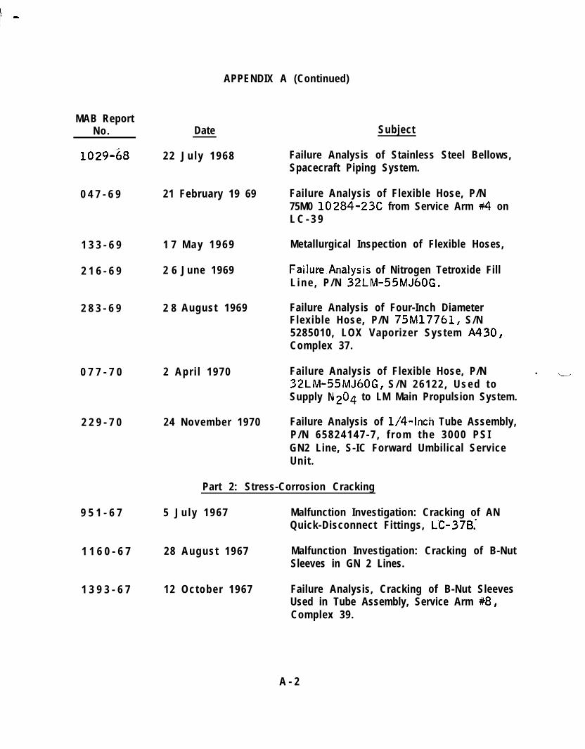
APPENDIX A (Continued)
MAB ReportNo.
1029-68
Date
2 2 J u l y 1 9 6 8
0 4 7 - 6 9 21 February 19 69
1 3 3 - 6 9
2 1 6 - 6 9
2 8 3 - 6 9
1 7 M a y 1 9 6 9
2 6 June 1969
2 8 August 1969
0 7 7 - 7 0 2 Apr i l 1970
2 2 9 - 7 0 24 November 1970
9 5 1 - 6 7
1 1 6 0 - 6 7
1 3 9 3 - 6 7
Part 2: Stress-Corrosion Cracking
5 J u l y 1 9 6 7 Malfunction Investigation: Cracking of ANQuick-Disconnect Fittings, LC-37B:
28 August 1967 Malfunction Investigation: Cracking of B-NutSleeves in GN 2 Lines.
12 October 1967 Failure Analysis, Cracking of B-Nut SleevesUsed in Tube Assembly, Service Arm ++8,Complex 39.
Subject
Failure Analysis of Stainless Steel Bellows,Spacecraft Piping System.
Failure Analysis of Flexible Hose, P/N75M0 10284-23C from Service Arm +I onL C - 3 9
Metallurgical Inspection of Flexible Hoses,
Failure.Analysis of Nitrogen Tetroxide FillL i n e , P / N 32LM-55MJ60G.
Failure Analysis of Four-Inch DiameterFlexible Hose, P/N 75M17761, S/N5285010, LOX Vaporizer System A430,Complex 37.
Failure Analysis of Flexible Hose, P/N . -.,32LM-55MJ60G, S / N 2 6 1 2 2 , U s e d t oSupply N2O4 to LM Main Propulsion System.
Failure Analysis of l/4-Inch Tube Assembly,P / N 6 5 8 2 4 1 4 7 - 7 , f r o m t h e 3 0 0 0 P S IGN2 Line, S-IC Forward Umbilical ServiceUnit.
A - 2
I-. .
MAB ReportNo.
!!5/066-
066-70
1 8 9 - 7 0
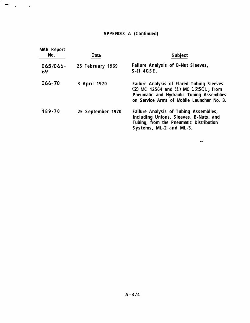
APPENDIX A (Continued)
25 February 1969
3 Apr i l 1970
25 September 1970
Subject
Failure Analysis of B-Nut Sleeves,S - I I 4 G S E .
Failure Analysis of Flared Tubing Sleeves(2) MC 12564 and (1) MC 125C6, fromPneumatic and Hydraulic Tubing Assemblieson Service Arms of Mobile Launcher No. 3.
Failure Analysis of Tubing Assemblies,Including Unions, Sleeves, B-Nuts, andTubing, from the Pneumatic DistributionSystems, ML-2 and ML-3 .
A - 3 / 4

APPENDIX B
Literature Survey of Corrosion and Corrosion Protection of Stainless Steels.
1.0. I N T R O D U C T I O N
The purpose of this literature survey is to review and assess the available recentliterature dealing with corrosion mechanisms, corrosion testing in sea coastenvironments, and the protective paint type coating systems. The first part ofthe report covers the literature on corrosion and corrosion testing of stainlesssteels. The second part of the report covers the literature on anti-corrosion coat-ings for stainless steels. The literature references used in the preparation ofthis report are included in the Bibliography.
. 2 . 0 C O R R O S I O N O F S T A I N L E S S S T E E L S
2 . 1 This portion of the report is a review of pertinent references obtained in asearch of Chemical Abstracts, for the period January, 1950 throughDecember 1967, and Corrosion Abstracts from 1961 througj 1967.Key words used in searching the Chemical Abstracts Indexes were “pittingcorrosion” and “stress corrosion” with references pertaining to the austen-itic stainless steels noted. In this search, three hundred and six abstractswere examined, and about twenty-five of these appeared to be of sufficientvalue to warrant examination of the entire articles. Of these twenty-five,several articles in foreign language journals were not obtained because ofthe time required to obtain translations.
-2.2 Approximately 1,000 abstracts were reviewed in Corrosion Abstracts,covering the following categories: On-Location Tests, Forms of LocalCell Attack, Marine Atmospheric Environment, Metallic Coatings, Non-Metallic Coatings, Multiple Metallic-Nonmetallic Coatings, FerrousMetals and Alloys, and Valves, Piping, and Meters. Twenty-one articleswere selected, but of these, ten were not.readily available, or were avail-able only in foreign ianguage.
2 . 3 This part of the report is subdivided into two sections, the first reviewingthe literature on pitting corrosion and exposure testing and the second onstress-corrosion cracking.
2 . 3 . 1 Pitting Corrosion and Exposure Testing
2.3.1-l The articles of most relevance to this study are prob-ably those dealing with the mechanisms of pitting
B - l
I -
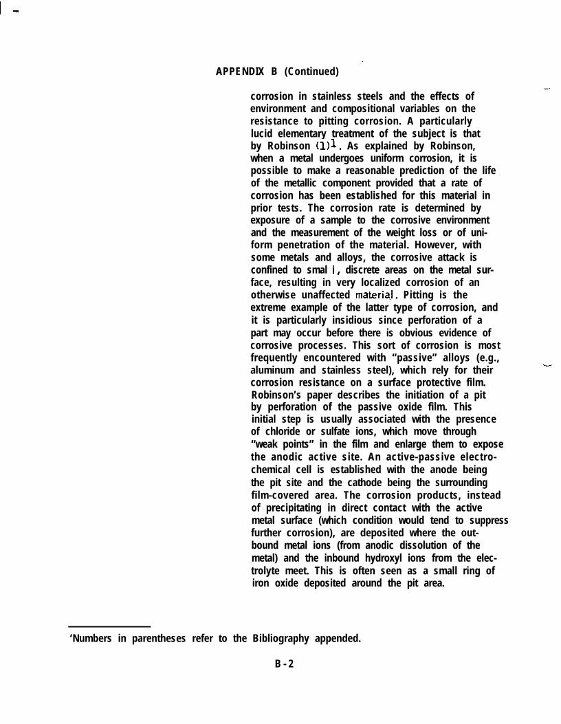
’APPENDIX B (Continued)-
corrosion in stainless steels and the effects ofenvironment and compositional variables on theresistance to pitting corrosion. A particularlylucid elementary treatment of the subject is thatby Robinson (111. As explained by Robinson,when a metal undergoes uniform corrosion, it ispossible to make a reasonable prediction of the lifeof the metallic component provided that a rate ofcorrosion has been established for this material inprior tests. The corrosion rate is determined byexposure of a sample to the corrosive environmentand the measurement of the weight loss or of uni-form penetration of the material. However, withsome metals and alloys, the corrosive attack isconfined to smal I, discrete areas on the metal sur-face, resulting in very localized corrosion of anotherwise unaffected materia.1. Pitting is theextreme example of the latter type of corrosion, andit is particularly insidious since perforation of apart may occur before there is obvious evidence ofcorrosive processes. This sort of corrosion is mostfrequently encountered with “passive” alloys (e.g.,aluminum and stainless steel), which rely for theircorrosion resistance on a surface protective film.Robinson’s paper describes the initiation of a pitby perforation of the passive oxide film. Thisinitial step is usually associated with the presenceof chloride or sulfate ions, which move through“weak points” in the film and enlarge them to exposethe anodic active site. An active-passive electro-chemical cell is established with the anode beingthe pit site and the cathode being the surroundingfilm-covered area. The corrosion products, insteadof precipitating in direct contact with the activemetal surface (which condition would tend to suppressfurther corrosion), are deposited where the out-bound metal ions (from anodic dissolution of themetal) and the inbound hydroxyl ions from the elec-trolyte meet. This is often seen as a small ring ofiron oxide deposited around the pit area.
‘Numbers in parentheses refer to the Bibliography appended.
B - 2
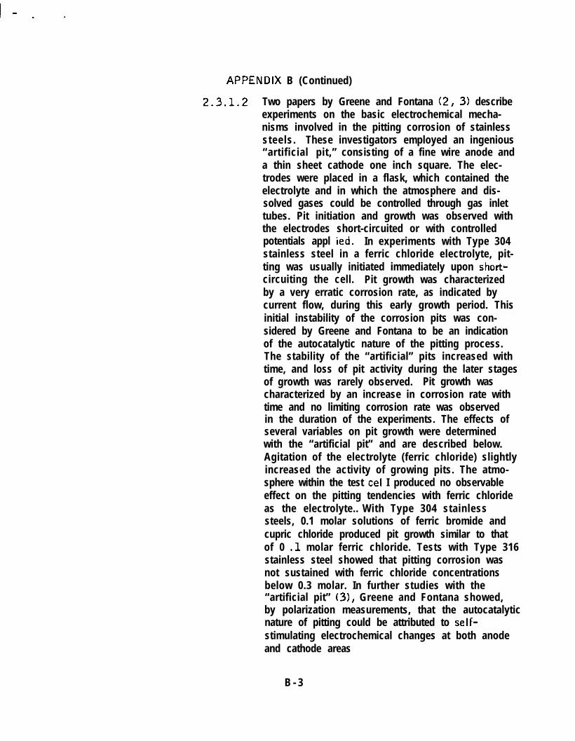
APPENDlX B (Continued)
2.3.1.2 Two papers by Greene and Fontana (2, 3) describeexperiments on the basic electrochemical mecha-nisms involved in the pitting corrosion of stainlesssteels. These investigators employed an ingenious“artificial pit,” consisting of a fine wire anode anda thin sheet cathode one inch square. The elec-trodes were placed in a flask, which contained theelectrolyte and in which the atmosphere and dis-solved gases could be controlled through gas inlettubes. Pit initiation and growth was observed withthe electrodes short-circuited or with controlledpotentials appl ied. In experiments with Type 304stainless steel in a ferric chloride electrolyte, pit-ting was usually initiated immediately upon short-circuiting the cell. Pit growth was characterizedby a very erratic corrosion rate, as indicated bycurrent flow, during this early growth period. Thisinitial instability of the corrosion pits was con-sidered by Greene and Fontana to be an indicationof the autocatalytic nature of the pitting process.The stability of the “artificial” pits increased withtime, and loss of pit activity during the later stagesof growth was rarely observed. Pit growth wascharacterized by an increase in corrosion rate withtime and no limiting corrosion rate was observedin the duration of the experiments. The effects ofseveral variables on pit growth were determinedwith the “artificial pit” and are described below.Agitation of the electrolyte (ferric chloride) slightlyincreased the activity of growing pits. The atmo-sphere within the test ccl I produced no observableeffect on the pitting tendencies with ferric chlorideas the electrolyte.. With Type 304 stainlesssteels, 0.1 molar solutions of ferric bromide andcupric chloride produced pit growth similar to thatof 0 .l molar ferric chloride. Tests with Type 316stainless steel showed that pitting corrosion wasnot sustained with ferric chloride concentrationsbelow 0.3 molar. In further studies with the“artificial pit” (31, Greene and Fontana showed,by polarization measurements, that the autocatalyticnature of pitting could be attributed to self-stimulating electrochemical changes at both anodeand cathode areas
B - 3

APPENDIX B (Continued)
2.3.1.3 ,A paper by Schwenk (4) describes studies to deter-mine in what potential range pitting will occur inaustenitic stainless steels, the kinetics of pitting,and what materials will inhibit pitting. Of particu-lar interest was the observation that with a Type316 stainless steel pitting occurs with sodiumchloride electrolytes in concentrations as low as0 .-1 molar. Schwenk found that as pitting corrosionproceeds to the point that a large number of activepits exist (and a relatively large total anode areais involved), a “repassivating” effect occurs. Also,growth of pits in irregular shapes is attributed topartial repassivation of active areas. The repassi-vating effect was found tobe dependent on molybdenumcontent (increasing with increased molybdenum).
2 . 3 . 1 . 4 Recent studies of the pitting potential in stainlesssteels are described in papers by Hospodaruk andPetrocelli (5) and Leckie and Uhlig (6). -‘In theformer paper, the authors described tests to deter-mine the pitting potentials of several stainlesssteels in nearly neutral chloride solutions. Mostof the prior work had been done with acid electro-lytes. The experiments by Hospodaruk andPetrocelli showed that the nucleation of pits on anotherwise passive surface is a function of the elec-trode potentia,l. For a given chloride ion concentra-tion and alloy composition, pitting does not occuruntil a certain potential is reached or exceeded.This pitting potential is characteristic of the alloyand may be used as a measure of the relative pittingtendency of various alloys. According to theseauthors, the mechanism by which chloride ion effectsthe initial breakdown of the passive film at certainsites is still in question and is presently beingexplored.
2 . 3 . 1 . 5 The L eckie and Uhl ig paper also affirms the exis-tence of a critical potential for pitting in stainlesssteels. The ability of certain ions, such as nitrate,to inhibit pitting of stainless steels in ferric chlo-ride solutions is explained as resulting from a shiftin the potential to a more noble value when the
B - 4

I-. .
APPENDIX B (Continued>
2 . 3 . 1 . 6
nitrate ion is present. Based on their experiments,these authors postulate a mechanism for destructionof the passive film on stainless steels as follows:at a sufficiently high surface concentration of chlo-ride ions, oxygen in the passive film is displacedlocally by chloride ions. At these points, theanodic overvoltage for dissolution of the stainlessalloy is considerably reduced wherever the metalis in contact with chloride ion compared to metalin contact with the oxygen, and hence metal ionsrapidly enter solution resulting in a pit.
Greene and Judd(7) have investigated the relationbetween dissolution kinetics and resistance to pit-ting corrosion in materials including 304L and316 stainless steel. They have shown that theratio of dissolution rates in the presence andabsence of chloride ion is inversely related to pit-ting resistance. In a paper by Tomasho<, Chernovaand Markova (8) an investigation of the influenceof alloying elements on the resistance of 18 Cr-14Ni steel to pitting corrosion is reported. Molybde-num, silicon, and \mnadium showed the greatestinfluence on corrosion resistance. Resistance topitting was greatly increased at 5 percent concen-trations. Additions of those elements caused thepit sites to shift from the grain surface near theboundaries to the grain boundaries.
2 . 3 . 1 . 7 The effects of alloy composition on pitting tendenciesof austenitic stainless steels were also describedin an excellent paper by Streicher (9). Streicher’sexperiments were performed with several “standard”steels , such as Types 302, 304, 304L, 316,316L,321, and 347, and some modified alloys - 302B(containing 2.50 percent silicon), a silicon-modified 316, and several alloys with high nitro-gen content. The pitting tendencies in chloridesolutions were evaluated for these alloys in twoconditions: (a) pickled (to reduce the effective-ness of the oxide coating) and (b) pickled andpassivated. These experiments revealed that the
B - 5

I -
APPENDIX 6 (Continued)
pitting tendency of Type 316 and Type 304 in thepickled condition was essentially the same but thepassivation treatment decreased pit initiation forall of the alloys. The response of Type 316 topassivation is much greater than that of Type 304,which is attributed to the effect of molybdenum inre-establishing the passive film, while decreasingthe carbon content decreased pit initiation. Steelscontaining higher amounts of nitrogen showed lesspitting than those containing normal amounts butno effect on pitting was associated with the pres-ence of stabilizing elements such as columbium inType 347 and titanium in Type 321.
2 . 3 . 1 . 8 A different approach to the problem of pitting cor-rosion, concentrating on the physical and chemicalcharacteristics of the protective film, was dis-cussed in an early paper by Rhodin (10). Rhodin’sfindings indicate that the film properties are.particu-larly sensitive to alloy composition, corrosivemedium, and surface treatments. These propertiesreflect the intrinsic capacity of a metal surface toprotect itself against corrosion. A specific exampleis that of a silicon-modified Type 3161, whosesuperior resistance to pitting corrosion was corre-lated with a mutual passive film enrichment in sili-con and molybdenum and corresponding film deple-tion in iron.
2 . 3 . 1 . 9 A paper by Alexander, Southwell, and Forgeson(11) describes exposure tests performed in thePanama Canal Zone on several stainless steels.The effects of several environments such as inland,lake water immersion, seashore, sea water meantide, and complete sea water immersion were deter-mined. Significant pitting was obtained only inpartial or complete immersion in sea water. Inthese tests frequency of pitting was less in Type316 than in Types 302 and 321. On the basis ofdepth of pitting, however, there was little differ-ence noted among these three alloys. K. G . Compton(12) discusses briefly the effects of location, local
B - 6
I - . c
APPENDIX B (Continued)
topography, humidity, temperature, rain, andatmospheric contamination on the exposure of testspecimens to marine atmosphere.
2 . 3 . 2 Stress-Corrosion Cracking
2.3.2.1 The occurrence of transgranular stress-corrosioncracking in austenitic stainless steels in serviceapplications stimulated considerable researchactivity on the subject in recent years. Since mostof these service failures involved high-temperatureapplications such as steam piping, etc., the test-ing methods applied in these investigations haveinvolved relatively high temperatures. Papers byStaehle, Beck, and Fontana (131, Thomas,Ferrari, and Allio (141, and Leu and Helle (151,describe tests in hot, aqueous chloride solutionsof varying chloride concentrations used to evaluatethe susceptibility of various alloys to stress-corrosion cracking. It was shwn in these papersthat, at temperatures of 400” F, Type 304 stain-less steel can undergo cracking at applied stressesas low as 2,000 psi and chloride concentrationsas low as 50 parts per million. While tests suchas these do not of course represent service condi-tions involved in our subject applications, they doyield useful information on the relative suscepti-bility of different alloys and different metallurgicalconditions of a given alloy. Papers by Uhlig andLincoln (16) and Hawkes, Beck, and Fontana(17) show that cold work generally increases thesusceptibility to cracking, with the most severeeffect being associated with about 10 percentreduction by cold work. In the Hawkes, Beck, and ’Fontana paper, differences in resistance of Types304, 309, and 316 to stress corrosion crackingwere reported to be minor.
2 . 3 . 2 . 2 Different results relative to the effects of alloycontent on stress corrosion were reported in papersby Bamartt, Stickler and van Rooyen (18) andStickler and Barnartt (19). These investigators
B - 7
--
..
APPENDIX B (Continued)
found that, in a more highly alloyed base steel(16 percent chromium, 20 percent nickel), addi-tions of molybdenum up to 1.5 percent or titaniumup to 0.5 percent increased the tendency to stress-corrosion cracking. It was postulated that themechanism by which this occurs is similar to thatproposed by Forty - a “restricted-s1 ip” crackingmechanism (20). According to this theory, whena crack is formed within the surface layer it willpropagate into the underlying metal only if dislo-cation movement is highly restricted. Propagationceases if the crack enters a “soft” region, such asa pre-existing slip band. Therefore, alloys thatreadily cross slip should be resistant to this typeof cracking. ‘Characteristically, alloys that readilycross slip have comparatively high stacking-faultenergies . Generally speakipg, the stacking faultenergies of the austenitic stainless steels are rela-tively low and, hence, cross slip is restricted.According to the papers previously cited, additionsof molybdenum and titanium further lower the stack-ing fault energies, thus further reducing the oppor-tunities for cross slip. The experimentalcited by these authors tends to confirm th i
datas theory.
3 . 0 A N T I - C O R R O S I O N C O A T INGS
_ 3 . 1 This part of the relport presents the results of a search conducted inChemical Abstracts for the period 1948 through February 1968, usingthefollowing terms as descriptors:
3 . 1 . 1 Coatings - stainless priming.
3 . 1 . 2 Enamels - Enameling of, - stainless.
3 . 1 . 3 Lacquers - Lacquering of, - stainless.
3 . 1 . 4 Paints - Painting of, - stainless.
3 . 1 . 5 Finishes - Finishing, - stainless.
3 . 1 . 6 Steel, Stainless - coating.
-
B - 8

APPENDIX B (Continued)
3 . 2
._
3 . 1 . 7 Steel, Stainless - corrosion.
3 . 1 . 8 Steel, Stainless - painting.
3 . 1 . 9 Steel, Stainless - priming.
Nine references were found to have some relevance to the subject study.Of these nine, four relate generally to surface preparation prior to paint-ing or to the application of fired enamel coatings. These articles werenot considered to be of significant practical importance to this program.The remaining five items were abstracts of patents. These are presentedin bibliographic form below.
3 . 2 . 1 Coating of Stainless Steel with Chromates for Salt SprayCorrosion Resistance
Chromating of stainless steel to improve its resistance to salt-spray corrosion (U.S. patent 2,991,205 4 July 1961). Thecorrosion resistance of stainless steel of all types--in industrialatmospheres or salt spray is improved by chromating, as withZn or Cd. The finish can then be restored by polishing or buff-ing without detriment to the corrosion resistance. The pre-ferred CrO3 bath and coating conditions are the same as appliedto ordinary steel (U. S . patent 2,768,104, 23 October1956) but no preliminary surface treatment other than cleaningis required. Chromate coatings weighing 40 mg/sq ft wereapplied to bright-finished Type 430 stainless steel strip byimmersion in an aqueous solution containing 2 percent Cr03and 0.66 percent sugar at 70” F, and Erichsen cups wereformed from coated and uncoated specimens and tested in a20 percent NaCl spray. Uncoated specimens rusted in 48hours, buffed specimens in 72, coated in 165, and buffedand coated specimens did not rust in 600 hours.
3 . 2 . 2 Coating of Stainless Steel with Organic Esters of Ti or Zr
Method of coating the surface with transparent film and theproduct resulting therefrom (U .S . patent 2,768,909,30 October 1956). A transparent flexible film is comprisedof hydrolysis products of organic esters of a metal containingTi or Zr, such as butyl titanate, ethyl titanate, etc. An ethyltitanate solution comprising 1.0 percent by weight of the ester,
B - 9

.
APPENDIX B (Continued)
the balance ethanol was prepared by dissolving titanate atroom temperature in the solvent. The solution thus obtainedwas sprayed onto a stainless steel sheet and was then air-dried for 40 hours, relative humidity approximately 50 per-cent. A thin, clear, transparent film resulted, which wasextremely hard and adherent to the steel and could not beremoved therefrom even by rubbing with a solvent soaked rag.
NOTE: No mention made in Chemical Abstracts of thissystem’s corrosion resistance.
3 . 2 . 3 Coating of Stainless Steel with Oxalates
“Activation of oxalate metal-coating compositions” byR . C. Gibson to Parker Rust Proof Company (U .S . patent2,617,749, 11 November 1952) .
An active oxalate solution for the protective coating of austen-itic stainless steel during mechanical work involving extensiveplastic deformation, which is used along with a soap lubricant,aqueous oxalic acid, ferric ion, and 1.5 - 40 percent thiocya-nate ion. In the preferred practice, the oxalic acid is in excessof that required to form ferric oxalate, the ferric ion is 0.4 to6 percent and the thiocyanate ion is 1.5 to 20 percent. Whenferrous oxalate is used in preparing the solution, Hadded to oxidize Fe* to Fe-. The coating is f
0 2 i sormed on
the steel by immersion in the solution for 3 - 15 minutes andmay be enhanced by dipping in a slurry of hydrated lime.
NOTE: There was no mention of field service corrosionprotection afforded by this coating.
3 . 2 . 4 Coating of Steel (Stainless) with black,coats
abrasion resistant
Black-coating stainless steel by H. W. Cobb to Armco SteelCorporation (U .S . patent 2,542,994, 27 February 1951) .
-
Adherent, flexible, abrasion-resistant black coatings are pro-duced on stainless steel by first immersing the steel in a moltenbath of Na2Cr207 and/or K2Cr207. Then, the coated metal
B - 1 0

APPENDIX B (Continued)
is subjected to an electrolytic cathodizing treatment in a fuseddichromate bath for 5 - 10 minutes at a current density of.05 - 4 . 0 amps/in2. .A stainless steel anode is used. Thetemperature of the fused salt baths is maintained at 320-4OOOfor Na2Cr207 or 400-500’ for the mixed salts. The stain-less steel is cleaned by the customary methods before theblackening treatment.
NOTE: There was no mention of field serviceprotection afforded by this coating.
corrosion
3 . 2 . 5 Coating on Stainless Steel, from hydroxyreaction DIC and TMP p. 17739a,
compound polymer6 4 , January June 1966
Hardened copolymers containing hydroxyl-. groups based onacrylates by G. Louis to Badische Anilin-and Soda -Fabrick, A. G. (German 1,201,556, 23 September 1965).
This article describes specific compounds that react and formcopolymers which may be spread on stainless steel forming anontacky film on standing at room temperature for 2 hours.
NOTE: Again, there was no reference to the degree ofcorrosion protection that might be afforded.
4 . 0 C O N C L U S I O N S
- 4 . 1 From this review of the accessible literature, the following conclusionsappear warranted:
4 . 1 . 1 Data from reported exposure tests in sea coast environmentshave very limited applicability in the subject study. Thesehave generally failed to reveal the serious degree of corrosionexperienced in the KSC area.
4 . 1 . 2 Theoretical studies indicate a superiority in the passive sur-face film of steel compositions containing molybdenum (e.g.,Type 316). Such films are more resistant to penetration andundergo repassivation more readily than steels with lowermolybdenum compositions (e.g. , Type 304). These considera-tions are consistent with test data, which show a lower pittingfrequency for Type 316 than for Type 304 but little difference
B - 1 1

I -
APPENDIX B (Continued)
in depth of pitting between the two alloys. Evidently, oncethe passive film is penetrated, the active-passive cell cor-rosion mechanism operates at virtually the same rate for allcompositions of the austenitic stainless steels. A beneficialeffect on the passive film was also obtained with experimentalsteels of unusually high silicon content. .
Stress-corrosion cracking, which is a serious problem withtube fittings of certain compositions in the KSC area, is notknown to be of serious concern in stainless steel tubing.However, data from the literature indicate a probable suscepti-bility of partially cold-worked material in chloride environment.There was also some indication that molybdenum may increasethe tendency for stress-corrosion cracking in hot chlorideenvironments, and a mechanism for this was proposed (restricted-slip mechanism). Whether this mechanism can operate at ordi-nary temperatures in an atmospheric chloride environment hasnot been established.
The patent literature describes several coating systems designed’for appl ication to stainless steels. Corrosion test data werepresented for only one of these, a zinc or cadmium chromate.A beneficial effect on corrosion resistance (by the salt-spraytest) was produced by the application of this coating.
B - 1 2
BIBLIOGRAPHYv
1 .
2 .
3 .
4 .
5 .
6 .
7 .
8 .
9 .
1 0 .
1 1 .
1 2 .
-
F. P. A. Robinson, “Pitting Corrosion: Cause, Effect, Detection and Preven-tion,” Corrosion Technology, August 1960, pp 237 - 239 and 266.
,-N. D. Greene and M. G. Fontana, “An Electrochemical Study of Pitting Corro-sion in Stainless Steels, Part I - Pit Growth,” Corrosion, V. 15, 1959,pp 32t - 38t .
N. D. Greene and M. G. Fontana, “An Electrochemical Study of Pitting Cor-rosion in Stainless Steels, Part 2 - Polarization Measurement,” Corrosion,v . 15,1959, p p 3 9 t - 4 4 t .
W. Schwenk, “Theory of Stainless Steel Pitting,” Corrosion, Vol. 20, 1964,p p 1 2 9 t - 1 3 7 t .
V. Hospardaruk and J. V. Petrocelli, “The Pitting Potential of Stainless Steelin Chloride Media,” Journal of the Electrochemical Society, September, 1966,p p 8 7 8 - 8 8 3 . i.
H. P. Leckie and H. H. Uhlig, “Environmental Factors Affecting the CriticalPotential for Pitting in 18-8 Stainless Steel, ” Journal of the ElectrochemicalSociety , December 1966, pp 1262 - 1267.
N . D. Greene and G . Judd, “Relation Between Anodic Dissolution and Resis-tance to Pitting Corrosion,” Corrosion, 21, No. 1 (1965) January.
N. D. Tomashov, G. P. Chernova, and 0. N. Markova, “Effect of Alloying-Elements on the Tendency of Stainless Chromium-Nickel Steels to Pitting Cor-rosion ,” U .S. Department of Commerce, Joint Publication Research ServiceReport 2229 1.
M . A . Streicher, “Pitting Corrosion of 18 Cr - 8 Ni Stainless Steel,” Journalof the Electrochemical Society, July 1956 pp 375 - 390.
Thor. N. Rhodin, “The Relation of Thin Films to Corrosion,” Corrosion Vol. 12,1 9 5 6 , p p 4 6 5 t - 4 7 5 t .
A. 1. Alexander, C. R. Southwell, and B. W. Forgeson, “Corrosion of Metalsin Tropical Environments, Part 5 - Stainless Steel,” Corrosion, Vol. 17,1 9 6 1 , p p 3 4 5 t - 3 5 2 t .
K. G. Compton, “Factors Influencing Measurement of Corrosion in Marine Atmo-sphere,” Materials Protection, 4, No. 12, (1965) December.
B - 1 3
! .I
BIBLIOGRAPHY (Continued)-’
1 3 . R. W. Staehle, F. H. Beck, and M. G. Fontana, “Mechanisms of StressCorrosion of Austenitic Stainless Steels in Chloride Waters,” Corrosion,V o l . 1 5 , 1 9 5 9 , p p 3 7 3 t - 3 8 1 t .
1 4 . K. C. Thomas, H. M. Ferrari , and R. J. All io, “Stress Corrosion of Type 304Stainless Steel in Chloride Environments,” Corrosion, Vol. 20, 1963,pp 89t - 92t .
1 5 . K. W. Leu and J. N. Helle, “The Mechanism of Stress Corrosion of AusteniticStainless Steels in Hot Aqueous Chloride Solutions,” Corrosion, Vol. 14,1 9 5 8 , p p 2 4 9 t - 2 5 4 t .
1 6 . H. H. Uhlig and J. Lincoln, Jr., “Chemical Factors Affecting Stress CorrosionCracking of 18-8 Stainless Steels,” Journal of the Electrochemical Society,J u n e 1 9 5 8 , p p 3 2 5 - 3 3 2 .
1 7 . H. P. Hawkes, F. H. Beck, and M. G. Fontana, “Effect of Applied Stress andCold Work on Stress Corrosion Cracking of Austenitic Stainless Steel by Boiling42 Percent Magnesium Chloride,” Corros ion, Vol . 19 , 1963 , pp 247t -1 5 3 t .
1 8 . S. Barnartt, R. Steickler, and D. von Rooyen, “Stress-Corrosion CrackingMechanism in Purified 16 Percent Cr - 20 Percent Ni Stainless Steels,”Corrosion Science, Vol. 2, 1963, pp 9 - 16.
1 9 . R. Steickler and S . Bamartt, “Mechanism of Stress Corrosion Cracking inStainless Steels,” Journal of the Electrochemical Society, April 1962,
‘ p p 3 4 3 - 3 4 4 .
-
2 0 . A. J Forty, Physical Metallurgy of Stress Corrosion Fracture (T. H. Rhodin,editor), pp 99, Interscience, New York, 1959.
B - 1 4
N A S A - U S C FE0171