m3 u7 pipe bending - ecollege bending.pdfmodule 3– unit 7 pipefitting phase 2 4 pipe bending...
TRANSCRIPT
TRADE OF
Pipefitting
PHASE 2
Module 3
Pipe Processes
UNIT: 7
Pipe Bending

Produced by
In cooperation with subject matter expert:
Finbar Smith
© SOLAS 2014

Module 3– Unit 7
Pipefitting Phase 2
Pipe Bending
Revision 2.0 September 2014
Table of Contents Unit Objective ........................................................................................................... 1 Learning Outcome .................................................................................................... 2 1.0 Bending Processes for Pipe Fitting ......................................................... 3
1.1 Pipe and Tube Bending ............................................................................. 3 1.2 Types of Bending Processes and Equipment Used .............................. 4 1.3 Press Bending ............................................................................................. 4 1.4 Rotary Draw Bending ................................................................................ 4 1.5 Mandrel Bending ........................................................................................ 5 1.6 3 Roll Bending ............................................................................................ 5 1.7 Bending Springs ......................................................................................... 6 1.8 Heat Induction Bending ............................................................................ 6 1.9 Sand Packing Hot-Slab Bending .............................................................. 6
2.0 Bending Pipe and Tube ............................................................................. 7 2.1 Parts of a Circle Relevant to Pipe Bending ............................................ 7 2.2 Formula for Determining the Length of Material to Form a 90° Bend
...................................................................................................................... 8 3.0 Effects on Pipe and Tube from the Bending Process .......................... 10
3.1 Physical Effects on Pipe and Tube from Bending ................................ 10 3.2 Mechanical Effects on Pipe and Tube from Bending .......................... 10 3.3 Annealing and Tempering ........................................................................ 10
4.0 Bending Plastic Pipes ................................................................................. 12 4.1 Heat Bending Plastic Pipes ....................................................................... 12 4.2 Safety Considerations for Bending Plastic Pipes ................................... 13 4.3 Guidelines and Safety Precautions for Bending Plastic Pipes ............. 13
5.0 Hazards and Safety Precautions Associated with Pipe Bending ......... 15 5.1 General Safety Precautions for Pipe and Tube Bending Equipment . 15 5.2 Safety Precautions for Hydraulic Pipe and Tube Bending Equipment
...................................................................................................................... 16 Exercises ..................................................................................................................... 18 Additional Resources ................................................................................................ 19
Module 3– Unit 7
Pipefitting Phase 2
1
Pipe Bending
Revision 2.0 September 2014
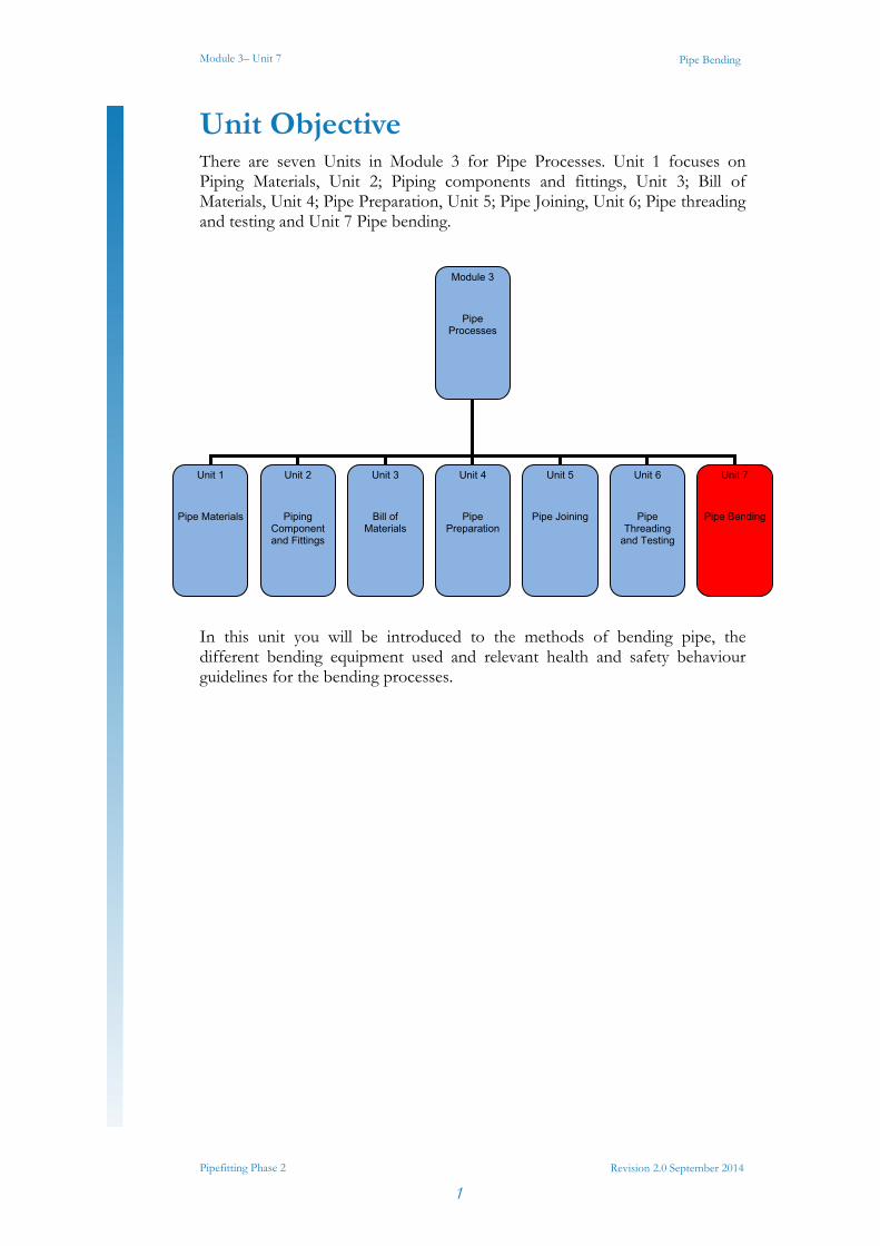
Unit Objective There are seven Units in Module 3 for Pipe Processes. Unit 1 focuses on Piping Materials, Unit 2; Piping components and fittings, Unit 3; Bill of Materials, Unit 4; Pipe Preparation, Unit 5; Pipe Joining, Unit 6; Pipe threading and testing and Unit 7 Pipe bending.
In this unit you will be introduced to the methods of bending pipe, the different bending equipment used and relevant health and safety behaviour guidelines for the bending processes.
Module 3
Pipe Processes
Unit 1
Pipe Materials
Unit 2
Piping Component and Fittings
Unit 3
Bill of Materials
Unit 4
Pipe Preparation
Unit 5
Pipe Joining
Unit 6
Pipe Threading
and Testing
Unit 7
Pipe Bending
Module 3– Unit 7
Pipefitting Phase 2
2
Pipe Bending
Revision 2.0 September 2014
Learning Outcome By the end of this unit each apprentice will be able to:
Describe the bending process and what methods are used for the different types of pipe.
List the types of bending equipment in common use in the pipefitting trade and their application.
Complete practical bending exercise in copper pipe as per Exercise Nos. 2.3.7a and 2.3.7b.
Complete mild steel pipe bending exercise using hydraulic bending equipment as per Exercise Nos. 2.3.7c and 2.3.7d.
Complete exercise using heat bending process as per Exercise Nos. 2.3.7e and 2.3.7f.

Module 3– Unit 7
Pipefitting Phase 2
3
Pipe Bending
Revision 2.0 September 2014
1.0 Bending Processes for Pipe Fitting
1.1 Pipe and Tube Bending Pipe bending machines are typically human powered, pneumatic powered, hydraulic assisted, or electric servo motor. In the pipe bending operation the tube may be supported internally or externally to preserve the cross section of the pipe. In operations where there is flexibility in the shape of the pipe, the pipe does not need to be supported, however there will be some deformation in the both the cross section of the overall pipe and the wall thickness in different areas of the bend.
Tube bending as a process starts with loading a tube into a pipe bender and clamping it into place between two dies, the clamping block and the forming die. The tube is also loosely held by two other dies, the wiper die and the pressure die. After that has been completed the fitter will start the bender, while the tube is pulled around the forming die creating an elbow, U-bend, 2-D or 3-D bent tubes. A three dimensional tube is a tube with each opening on different planes. A two dimensional tube is a tube with each opening on the same plane. The picture below shows a typical manual pipe benders with the main parts named.
Manual pipe benders for bending thin wall tube
Key Learning Points Describe the process of Pipe Bending
Identify the different bending processes used in pipe fitting
Brief description of each process
Module 3– Unit 7
Pipefitting Phase 2
4
Pipe Bending
Revision 2.0 September 2014
1.2 Types of Bending Processes and Equipment Used
Pipe bending techniques are varied and offer different advantages and disadvantages depending on the function of the bend and the type of material being bent. Some use mechanical force and some use heat treatment, the most common are as follows:
Press Bending
Rotary Draw Bending
Mandrel bending
3 Roll Bending
Bending springs
Heat induction bending
Sand packing/hot-slab bending
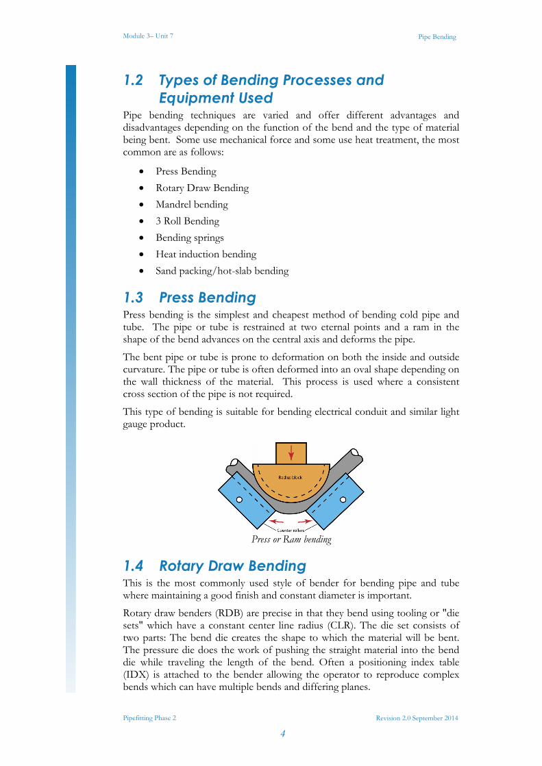
1.3 Press Bending Press bending is the simplest and cheapest method of bending cold pipe and tube. The pipe or tube is restrained at two eternal points and a ram in the shape of the bend advances on the central axis and deforms the pipe.
The bent pipe or tube is prone to deformation on both the inside and outside curvature. The pipe or tube is often deformed into an oval shape depending on the wall thickness of the material. This process is used where a consistent cross section of the pipe is not required.
This type of bending is suitable for bending electrical conduit and similar light gauge product.
Press or Ram bending
1.4 Rotary Draw Bending This is the most commonly used style of bender for bending pipe and tube where maintaining a good finish and constant diameter is important.
Rotary draw benders (RDB) are precise in that they bend using tooling or "die sets" which have a constant center line radius (CLR). The die set consists of two parts: The bend die creates the shape to which the material will be bent. The pressure die does the work of pushing the straight material into the bend die while traveling the length of the bend. Often a positioning index table (IDX) is attached to the bender allowing the operator to reproduce complex bends which can have multiple bends and differing planes.
Module 3– Unit 7
Pipefitting Phase 2
5
Pipe Bending
Revision 2.0 September 2014
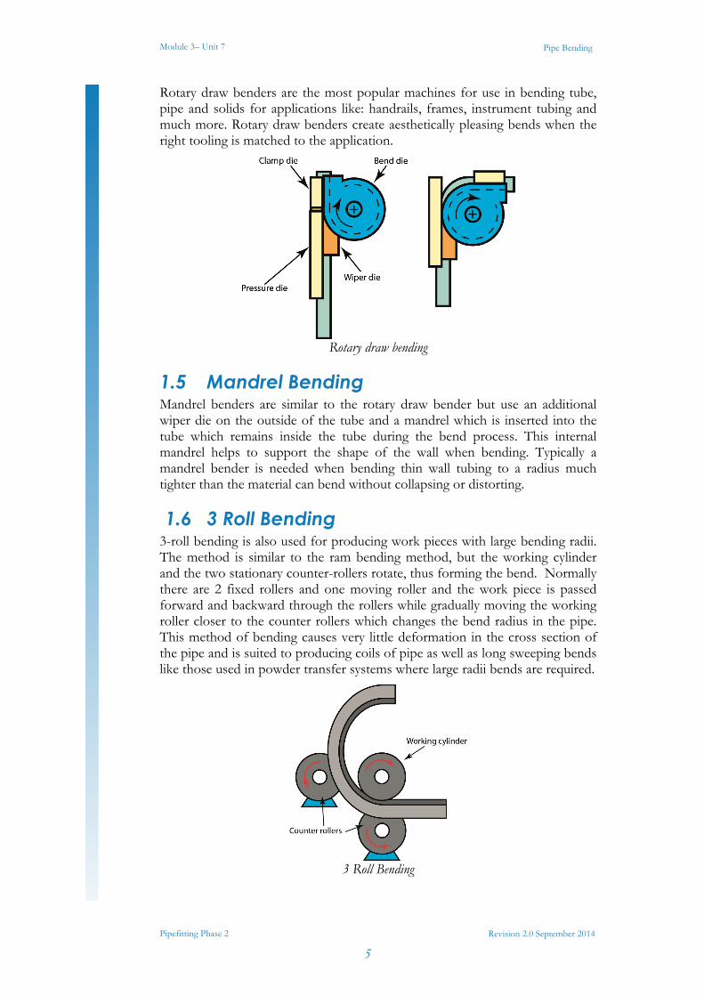
Rotary draw benders are the most popular machines for use in bending tube, pipe and solids for applications like: handrails, frames, instrument tubing and much more. Rotary draw benders create aesthetically pleasing bends when the right tooling is matched to the application.
Rotary draw bending
1.5 Mandrel Bending Mandrel benders are similar to the rotary draw bender but use an additional wiper die on the outside of the tube and a mandrel which is inserted into the tube which remains inside the tube during the bend process. This internal mandrel helps to support the shape of the wall when bending. Typically a mandrel bender is needed when bending thin wall tubing to a radius much tighter than the material can bend without collapsing or distorting.
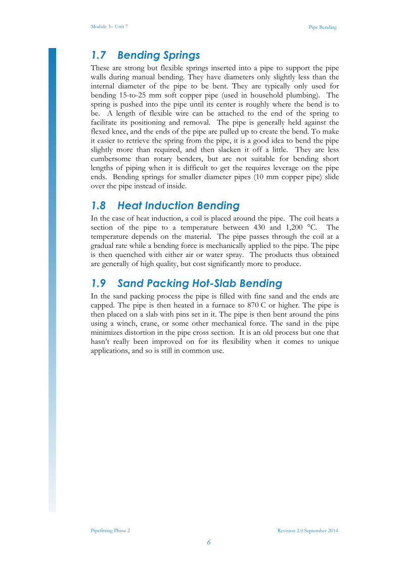
1.6 3 Roll Bending 3-roll bending is also used for producing work pieces with large bending radii. The method is similar to the ram bending method, but the working cylinder and the two stationary counter-rollers rotate, thus forming the bend. Normally there are 2 fixed rollers and one moving roller and the work piece is passed forward and backward through the rollers while gradually moving the working roller closer to the counter rollers which changes the bend radius in the pipe. This method of bending causes very little deformation in the cross section of the pipe and is suited to producing coils of pipe as well as long sweeping bends like those used in powder transfer systems where large radii bends are required.
3 Roll Bending
Module 3– Unit 7
Pipefitting Phase 2
6
Pipe Bending
Revision 2.0 September 2014
1.7 Bending Springs These are strong but flexible springs inserted into a pipe to support the pipe walls during manual bending. They have diameters only slightly less than the internal diameter of the pipe to be bent. They are typically only used for bending 15-to-25 mm soft copper pipe (used in household plumbing). The spring is pushed into the pipe until its center is roughly where the bend is to be. A length of flexible wire can be attached to the end of the spring to facilitate its positioning and removal. The pipe is generally held against the flexed knee, and the ends of the pipe are pulled up to create the bend. To make it easier to retrieve the spring from the pipe, it is a good idea to bend the pipe slightly more than required, and then slacken it off a little. They are less cumbersome than rotary benders, but are not suitable for bending short lengths of piping when it is difficult to get the requires leverage on the pipe ends. Bending springs for smaller diameter pipes (10 mm copper pipe) slide over the pipe instead of inside.
1.8 Heat Induction Bending In the case of heat induction, a coil is placed around the pipe. The coil heats a section of the pipe to a temperature between 430 and 1,200 °C. The temperature depends on the material. The pipe passes through the coil at a gradual rate while a bending force is mechanically applied to the pipe. The pipe is then quenched with either air or water spray. The products thus obtained are generally of high quality, but cost significantly more to produce.
1.9 Sand Packing Hot-Slab Bending In the sand packing process the pipe is filled with fine sand and the ends are capped. The pipe is then heated in a furnace to 870 C or higher. The pipe is then placed on a slab with pins set in it. The pipe is then bent around the pins using a winch, crane, or some other mechanical force. The sand in the pipe minimizes distortion in the pipe cross section. It is an old process but one that hasn’t really been improved on for its flexibility when it comes to unique applications, and so is still in common use.

Module 3– Unit 7
Pipefitting Phase 2
7
Pipe Bending
Revision 2.0 September 2014
2.0 Bending Pipe and Tube
2.1 Parts of a Circle Relevant to Pipe Bending When bending a pipe to any radius it should be remembered that you are constructing part of a circle.
The parts of a circle relevant to a pipe bending are:
The circumference - the outer rim of the circle.
The radius - a straight line from the centre of the circle to the circumference.
The diameter - a straight line going from one side of the circumference to the other passing through the centre. The diameter is twice the length of the radius
Every circle has 360°, as shown below.
Parts of a Circle 360°in a Circle
Therefore, there are four 90° segments in every circle.
Four 90° Segments in a Circle
A 90 bend involves bending a pipe through ¼ of a circle.
Key Learning Points Identify the parts of a circle relevant to pipe bending
Identify how to calculate the length of pipe required to form a 90º bend.

Module 3– Unit 7
Pipefitting Phase 2
8
Pipe Bending
Revision 2.0 September 2014
2.2 Formula for Determining the Length of Material to Form a 90° Bend
In the following examples the following abbreviations will be used:
C = Circumference
R = Radius
D = Diameter
π = 3.142
Example 1 Calculate the total length of pipe to be heated to bend a pipe through 90° to a radius of 75mm.
To carry out this calculation we must find the length of the circumference and divide it by 4:
If R = 75mm
Then D = 150mm
C = π D
Therefore: C = 3.142 X 150mm
C = 471mm
Length of pipe to be heated = 471 ÷ 4 = 117.75
Which can be written as 118mm.
Example 2 Calculate the total length of pipe to be heated to bend a pipe through 180° to a radius of 150mm.
To carry out this calculation we must find the length of the circumference and divide it by 2:
If R = 150
Then D = 300mm
C = π D
Therefore: C = 3.142 X 300mm
C = 943mm
Length of pipe to be heated = 943 ÷ 2 = 471.5
Which can be written as 472mm.

Module 3– Unit 7
Pipefitting Phase 2
9
Pipe Bending
Revision 2.0 September 2014
Example 3 Calculate the total length of pipe required to bend a pipe through 90° to a radius of 50mm.
To carry out this calculation we must find the length of the circumference and divide it by 4:
If R = 50
Then D = 100mm
C = π D
Therefore: C = 3.142 X 100mm
C = 314.2mm
Length of pipe required = 314 ÷ 4 =78.5
Which can be written as 79mm.

Module 3– Unit 7
Pipefitting Phase 2
10
Pipe Bending
Revision 2.0 September 2014
3.0 Effects on Pipe and Tube from the Bending Process
3.1 Physical Effects on Pipe and Tube from Bending
Depending on the bending method used and the material qualities of the pipe or tube being bent some of the following physical effects can be seen after bending:
Wrinkles on the inner side of the bend
Stretching of the wall on the outer side of the bend
Thinning of the wall thickness on the outer side of the bend
Deformation of the cross section of the pipe or tube causing it to reduce and form an oval shape.
3.2 Mechanical Effects on Pipe and Tube from Bending
The mechanical properties of the materials are also altered during the bending process.
Cold forming causes yield and tensile strengths to rise by 10%
Elongation may decrease by as much as15%
Bending of the pipe will also tend to result in distortions of the cross section. The distortions are greater the tighter the radius of the pipe.
3.3 Annealing and Tempering Annealing is the treatment of a metal or alloy to reduce its brittleness and improve its ductility. Annealing is often referred to as the softening of a metal. If a metal becomes work hardened (by bending) it may require softening before work is continued, otherwise it might fracture. Annealing is achieved by the application of heat.
Copper pipes are annealed before spring bending. The pipe is heated to a dull red colour and then allowed to cool or quenched in cold water.
Key Learning Points Identify changes in the physical characteristics of pipe and tube
from bending
Identify changes in the mechanical characteristics of pipe and tube from bending
Identify the benefits of heat treatment for pipe and tube bending.

Module 3– Unit 7
Pipefitting Phase 2
11
Pipe Bending
Revision 2.0 September 2014
Tempering or hardening, is a process of improving the characteristics of a metal, especially steel. Tempering is carried out by heating the metal to a high temperature and then cooling it, usually by quenching it in oil or water.
Cold chisels, screwdrivers, bending springs and the jaws of stilsons are examples of tools which are tempered.

Module 3– Unit 7
Pipefitting Phase 2
12
Pipe Bending
Revision 2.0 September 2014
4.0 Bending Plastic Pipes
4.1 Heat Bending Plastic Pipes Bending of plastic pipes may be desirable under certain conditions where long-radius bends and unusual configurations are required. It is possible to bend various sizes and wall thicknesses of rigid PVC-U, PVC-C and ABS pipe using heat bending techniques for long-radius sweeps for conduit and flow conditions. Irregular angles and U-bends for thermal compensation, and offsets in congested areas can be successfully achieved.
Guidelines for heat bending of plastic pipes
Successful bending requires that the appropriate amount of heat be applied uniformly to the required length of pipe to be bent. This presents the greatest challenge for field bending, as the heating method used must provide the necessary amount of heat over the required length of pipe in a reasonable amount of time. Several common pipe heating methods used in the field involve the use of hot air ovens, electric box heaters, electric pipe heating blankets, internal electric coiled heating springs and flameless hot gas torches. Temperatures necessary to heat the pipe are dependent on pipe size and the severity of the desired bend radius. In general, PVC pipe should be heated from 100°C to 135°C for the minimum amount of time necessary to achieve uniform softening. Care should be taken to avoid exposing the pipe to bending temperatures for an excessive length of time, as irreparable distortion and deformation will occur. Localized overheating must be avoided. Successful minor bends (< 30°) can be achieved with minimum distortion in the lower temperature range (100°C) without internal support.
Key Learning Points Identify specific hazards pertinent to pipe and tube bending
Identify how these hazards are eliminated or minimised
Identify how hazards towards others are minimised

Module 3– Unit 7
Pipefitting Phase 2
13
Pipe Bending
Revision 2.0 September 2014
Sharp bends (> 30°) require higher temperatures (120°-135°C) as well as internal support. Filling the pipe with fine grain sand or perlite prior to heating provides the internal support necessary to prevent wall distortion/collapse while at the same time provides an excellent medium for uniform heat distribution during the heating process.
4.2 Safety Considerations for Bending Plastic Pipes
It should be noted that most bending procedures will induce stress into the pipe wall which can be retained in the material after the bend radius is formed. The amount of stress induced is dependent on the severity of the bend, the diameter and wall thickness of the pipe bent, and the bending method used. This residual stress will be added to the normal stresses created by internal pressure, installation procedures, and the effects of temperature. Therefore, pipe bending should be limited to applications for use at ambient temperatures or lower where maximum operating pressures are not utilized. The use of a filling medium during the bending process may also cause slight pitting and other interior surface blemishes depending on the method used.
Attempting to form bends in rigid thermoplastic piping at temperatures too low can induce excessive stress into the pipe, thereby jeopardizing its physical performance.
4.3 Guidelines and Safety Precautions for Bending Plastic Pipes
Please follow these safety precautions prior to conducting any heat bending procedures on plastic pipes.
Bending procedures must be conducted in a well ventilated area, using protective clothing (safety glasses, gloves, apron etc.) to prevent damage or injury.
Do not expose pipe to open flames or excessive temperatures.
Bends greater than 30° require internal pipe support to prevent distortion.
Common methods used to provide internal support to the pipe during the bending process include using a filling medium such as fine sand or perlite (cat litter), or inserting a coiled spring into the pipe, or in some cases providing internal pressure.
Compact filling medium prior to bending as much as possible to remove any air pockets prior to heating.
The pipe ends should be capped or plugged.
Minimum radius at bend should not be less than 5 times the pipe outside diameter to prevent kinking. Calculate required length of bend based on angle needed, and heat this entire area uniformly.
Avoid overheating.
After the bend is completed, cool the bend with water to "set” the pipe at the desired angle.

Module 3– Unit 7
Pipefitting Phase 2
14
Pipe Bending
Revision 2.0 September 2014
Once the bend is formed and cooled, the filling medium is emptied from the pipe and any remaining particles can be easily removed by rinsing with water.
To provide fabrication consistency, standard pipe bending forms which provide the required radius or plywood jigs can be used.
Due to the recovery characteristics of the material, the pipe should be bent slightly beyond the desired radius and allowed to spring back to the required angle once uniformly heated at the correct temperature.
Module 3– Unit 7
Pipefitting Phase 2
15
Pipe Bending
Revision 2.0 September 2014
5.0 Hazards and Safety Precautions Associated with Pipe Bending
5.1 General Safety Precautions for Pipe and Tube Bending Equipment
When operating pipe and tube bending equipment the operator should be properly trained and supervised and observe all the general safe working procedures required for bending processes. While this is not meant to be an exhaustive list some specific points to note for pipe or tube bending are as follows:
Always -
Comply with the prescribed safety precautions and fire-prevention guidelines for the workshop.
Ensure the pipe bender is in sound condition and good working order. Take action for immediate repair or replacement of damaged parts. Use recommended parts only. The use of improper parts may be dangerous and will invalidate the machine warranty.
Do not assemble when tired or when under the influence of drugs or medication.
DO NOT allow untrained persons to operate the pipe bender.
Keep pipe bender and associated parts clean for best and safest performance.
Wear ANSI-approved safety goggles and heavy-duty work gloves during use.
As the pipe or tubing is being bent, there is a significant pinch hazard created. Keep hands, fingers, feet, and any item which may be injured or damaged away from the Tube Bender and hinge point areas of this tool when in operation.
Locate the pipe bender in a suitable, well lit working area.
Keep working area clean, tidy and free from unrelated materials.
Use on level and solid ground, preferably concrete.
Ensure all non-essential persons keep a safe distance whilst the pipe bender is in use.
Key Learning Points Identify specific hazards pertinent to pipe and tube bending
Identify how these hazards are eliminated or minimised
Identify how hazards towards others are minimised
Identify safety precautions to be observed while pipe and tube bending.

Module 3– Unit 7
Pipefitting Phase 2
16
Pipe Bending
Revision 2.0 September 2014
When bending pipe or tube, the bender should be in a horizontal position with sufficient clear space for the end of the pipe to move through the bending arc.
Pipe benders designed to bend soft metal pipe or tubing, such as copper or aluminum, should not be used to bend hard metal pipe, such as black iron pipe. You will damage the equipment.
Do not attempt to bend brittle materials, such as glass or hard plastic. Those materials may shatter and potentially cause injury.
5.2 Safety Precautions for Hydraulic Pipe and Tube Bending Equipment
The following are generic guidelines for hydraulic pipe and tube bending equipment, as there are many different suppliers of bending equipment it is not possible to provide a specific check list. This information does not replace the manufacturer’s instruction guide, it is meant only to acquaint the operator with some basic functions and safety tips that he/she must be aware of.
Equipment, particularly hydraulic power sources, vary considerably in their control and safety arrangements and therefore it is important to verify that actual equipment used is set-up correctly.
Before each use, inspect the Pipe Bender for bent or damaged components.
Check that bending die is correctly seated on ram and that the roller shafts are fully engaged in the frame and pinned before operating hydraulic unit.
Regularly wipe down and clean the tool to keep it in best condition.
Keep hands away from die and rollers when bending pipe.
Use a qualified person to lubricate and maintain the hydraulic unit.
Confirm that the recommended hydraulic oil is used during maintenance.
DO NOT top up system with brake fluid. Use hydraulic oil only.
DO NOT operate the pipe bender if damaged.
DO NOT exceed the rated capacity of the hydraulic unit
DO NOT use the pipe bender for purposes other than that for which it is intended.
DO NOT alter the settings of the pressure control valve.
When not in use, store the tool in a clean, dry, safe location out of reach of children and other unauthorized persons.
Ensure that you read, understand safety instructions before operating the pipe bender.
With the hydraulic unit release valve open and the ram fully retracted, fit the appropriate sized die to the ram.
Move pipe rollers and shafts to appropriate holes in frame and ensure that shafts are properly fitted and secured using hitch pins.

Module 3– Unit 7
Pipefitting Phase 2
17
Pipe Bending
Revision 2.0 September 2014
Introduce the pipe between die and rollers, positioning it so that the centre of the required bend in the pipe is over the centre of the die.
Close release valve and pump handle until the required degree of bend is achieved.
Using the end of the handle, open the release valve and ram will retract under spring tension.
Annually, replace hydraulic oil using correctly rated hydraulic jack oil. With ram fully retracted, drain and refill to bottom of filler plug hole.
When connecting the high-pressure hose with male and female quick connects ensure that both ends are clean and clear of dirt and contamination and that there is no pressure in the system before making the connection.
Maintain product labels and nameplates. These carry important safety information.
Please refer to your instructor for specific instruction and additional safety information where required.

Module 3– Unit 7
Pipefitting Phase 2
18
Pipe Bending
Revision 2.0 September 2014
Exercises Complete tube bending exercise in copper tube as per Exercise Nos.
2.3.7a and 2.3.7b.
Complete mild steel pipe bending exercise using hydraulic bending equipment as per Exercise Nos. 2.3.7c and 2.3.7d.
Complete exercise using heat bending process as per Exercise Nos. 2.3.7e and 2.3.7f.
State why it may be necessary to anneal a pipe before bending.
Calculate the amount of pipe to be heated to form a 90º bend with a radius of 150mm.
Calculate the amount of pipe to be heated to form a 360º loop with a radius of 400mm.
State why pipe benders should bend pipe in a horizontal axis?
Module 3– Unit 7
Pipefitting Phase 2
19
Pipe Bending
Revision 2.0 September 2014
Additional Resources Nayyar, P.E., Mohinder L. (2000). "A1". in Mohinder L. Nayyar, P.E..
Piping Handbook (7th ed.). New York: McGraw-Hill. ISBN 0-07-047106-1.
David L. Goetsch (2000). Technical Drawing (5th ed.). Thompson Delmar Learning ISBN: 1-4018-5760-4
International standard ISO 7-1: Pipe threads where pressure-tight joints are made on the threads — Part 1: Dimensions, tolerances and designation. International Organization for Standardization, Geneva.
BS EN 10226: Pipe threads where pressure tight joints are made on the threads. (The European version of ISO 7.) a) Part 1: Taper external threads and parallel internal threads —
Dimensions, tolerances and designation. b) Part 2: Taper external threads and taper internal threads —
Dimensions, tolerances and designation.
BS 21: Pipe threads for tubes and fittings where pressure-tight joints are made on the threads (metric dimensions). British Standards Institution, 1985. (Superseded by BS EN 10226:2004).
International standard ISO 228-1: Pipe threads where pressure-tight joints are not made on the threads — Part 1: Dimensions, tolerances and designation.
BS 2779: Specification for pipe threads for tubes and fittings where pressure-tight joints are not made on the threads (metric dimensions), 1986.
BS EN 10226-1:2004
ASME B31.9 Building Services Piping; 937 – Leak Testing, 1996 Edition
Elements of Plumbing by Samuel Edward Dibble, 2010

Castleforbes House Castleforbes Road
Dublin 1