m3 tutorial
DESCRIPTION
milemium 3TRANSCRIPT

Page 1 of 43
Millenium 3 Tutorial

Page 2 of 43
Tutorial Millenium 3 Contents
1 INTRODUCTION………………………………………………………………………….…………….4 2 PRODUCTS..................................................................................................................................5 3 GETTING STARTED WITH THE MILLENIUM 3.........................................................................5
3.1 PC RESOURCES: ...........................................................................................................5 3.2 INSTALLING THE SOFTWARE WORKSHOP................................................................5 3.3 CONNECTION TO THE PC.............................................................................................6
4 M3 SOFTWARE ENVIRONMENT………………………...............................................................6 4.1 ACCESSING HELP ..................................................................................................................6 4.2 TOOLBARS...............................................................................................................................7 5 FUNCTIONS..................................................................................................................................8 5.1 INPUTS/OUTPUTS.......................................................................................................................8 5.2 CONTROL FUNCTIONS.............................................................................................................10 5.3 HMI/COMMUNICATION FUNCTIONS…………………………...................................................15 5.4 PROGRAMMING FUNCTIONS ..................................................................................................18 5.5 CALCULATION FUNCTIONS .....................................................................................................19 5.6 LOGIC FUNCTIONS ...................................................................................................................21 5.6 SFC/GRAFCET FUNCTIONS .....................................................................................................21 6 STARTING AN APPLICATION....................................................................................................22 6.1 THE EDIT WINDOW.................................................................................................................22 6.2 EDITING YOUR PROGRAM: EDIT MODE .............................................................................24
6.2.1 Supervision...................................................................................................................25 6.2.2 Import............................................................................................................................25
6.3 TESTING YOUR PROGRAM: SIMULATION MODE ...............................................................25 6.3.1 Front panel display ........................................................................................................25 6.3.2 Simulation mode parameters..........................................................................................25
6.4 WRITING TO THE CONTROLLER AND RUNNING.................................................................26 6.5 MONITORING MODE................................................................................................................26 6.6 PRINTING YOUR APPLICATION..............................................................................................27 7 MILLENIUM IN RUN MODE.............................................................................................................28 7.1 THE DISPLAY. ............................................................................................................................28 7.2 ACCESSING THE MENU............................................................................................................28 7.3 MENU STRUCTURE ..................................................................................................................28 7.4 RUN/STOP..................................................................................................................................29
7.4.1 Accessing the menu with a password..............................................................................29 7.5 SETTING THE DATE AND TIME................................................................................................29
7.5.1 Setting the time on the Millenium from the software workshop.......................................29 7.5.2 Setting the time on the Millenium from the front panel ....................................................30 7.5.3 Calibration........................................................................................................................30
7.6 VALUES IN THE BLOCKS WHICH CAN BE MODIFIED............................................................30 7.7 MODIFYING A VALUE BY SELECTING FBD BLOCKS.............................................................31 7.8 MODIFYING A VARIABLE USING DISPLAY BLOCKS. ............................................................32

Page 3 of 43
7.9 FAULT ................................................................................................................................................33
8 PASSWORD FUNCTION...................................................................................................................33 8.1 YOU HAVE LOST YOUR PASSWORD...................................................................................34
9 FRONT PANEL LOCK .......................................................................................................................34 9.1 UNLOCKING THE FRONT PANEL...........................................................................................34
10 MEMORY MODULE...............................................................................................................................34
10.1 SAVING A CONTROLLER PROGRAM TO THE MODULE....................................................34 10.2 TRANSFERRING A MODULE PROGRAM TO THE MILLENIUM.........................................35
10.2.1 Sequence.................................................................................................................................35
10.2.2 The front panel is locked .......................................................................................................35 10.2.3 The Millenium program is protected by a password ........................................................35
10.2.4 The controller program is protected by a password and the front panel is locked ….35 10.3 COMMENTS ON USING THE MEMORY MODULE ...............................................................35 10.4 EXAMPLE OF USING THE MEMORY MODULE ....................................................................35
11 APPLICATION-SPECIFIC FUNCTIONS...........................................................................................36
11.1 APPLICATION-SPECIFIC FUNCTION IN THE SOFTWARE WORKSHOP......................36
11.2 APPLICATION-SPECIFIC FUNCTION IN THE MILLENIUM................................................36 11.3 MADE-TO-ORDER APPLICATION-SPECIFIC FUNCTION....................................................37
12 COMMUNICATION OPTIONS……………………………………......................................................37
12.1 COMMUNICATION VIA MODBUS EXTENSION................................................................37 12.1.1 Functional description.................................................................................................................37 12.1.1 Parameters setting..................................................................................................................37 12.1.1 Data exchange.........................................................................................................................38
12.2 COMMUNICATION VIA ETHERNET EXTENSION...........................................................38 12.1.1 Features....................................................................................................................................39 12.1.1 Parameters setting..................................................................................................................39 12.1.1 Data exchange.........................................................................................................................39
12.3 MODEM COMMUNICATIONS.....................................................................................................39 13 EXAMPLE OF AN FBD APPLICATION............................................................................................40
13.1 SPECIFICATIONS.………………….…………………………………….……….……...……...40 13.2 PROGRAM DESCRIPTION……….……….……………………………………..……...……...40 13.3 SUMMARY……….……….………………………………………………………..……....……...40

Page 4 of 43
TUTORIAL Millenium 3
1 INTRODUCTION
Programming a Millenium 3 logic controller is simple and straightforward. This can be accomplished
using either Ladder Logic (LD) or the more intuitive Function Block Diagrams(FBD).
LD language: Ladder language Ladder Diagram (LD) language is a graphic language. It can be used to transcribe relay diagrams, and is suited for combinational programs. You can use basic graphic symbols: contacts, coils, and blocks. Specific calculations can be executed within the operation blocks. It has certain limitations: you can’t use analog inputs and there is no option for arithmetic operations.
FBD language: Function Block Diagram FBD mode allows graphic programming based on the use of predefined function blocks. It offers a large range of basic functions: timer, counters, logic, etc.
These languages use:
Predefined function blocks: Timers, Counters
Specific Functions: Time Management, Data Conversion, Communication, etc.
For simple programs both programming options are available. For more complex applications FBD is
the recommended option. This document will focus only on the FBD language.
Operating Modes
There are several operating modes for the programming workshop:
Edit mode: The Edit mode is used to construct programs in FBD mode, which corresponds to the development of the application. In this mode you can: create macros, password protect your program, display dependencies between blocks, display a parameter summary table, preview function blocks by theme, or obtain online help for each function block.
Simulation mode: When in Simulation mode the program is executed offline directly in the programming workshop (simulated on the PC). Each action on the chart (changing the state of an input, output forcing) updates the simulation windows. You can simulate a power failure or program timing, modify analog variables via the Millenium’s virtual screen, or create a time-based jump event without changing the time on the PC.

Page 5 of 43
Monitoring mode: When in Monitoring mode the program is executed on the controller and the programming workshop is connected to the controller (PC controller connection). In this mode you can view machine operation in near real time on your PC, modify parameters via the front panel, or conduct progressive debugging and validate each part of the application.
In simulation and monitoring modes, it is possible to:
View the output states and function block parameters of the program corresponding to the wiring
sheet in the supervision window.
Force the inputs/outputs to test program behavior under specific conditions.
2 PRODUCTS
3 GETTING STARTED WITH THE MILLENIUM 3
The MILLENIUM 3 is programmed using the CLS M3 software workshop. It should therefore be
connected to your PC. You can not create or modify a program from the Millenium front panel.
3.1 PC resources:
PC Pentium II 300 MHz (600 MHz recommended), 128 Mb of RAM memory (256 MB recommended). Compatible with Windows 2000, NT 4.0 SP5, XP, Vista and Windows 7.
3.2 Installing the software workshop.
If you have the M3 SOFT CD ROM (Part Number 88 970 111) insert it into your PC and follow the instructions.
Programming Cable
Memory Cartridge

Page 6 of 43
The programming software is also available for download from www.crouzet.com. Once downloaded extract the files and run the Setup.exe file. This will start the installation process.
Multiple installations are possible with the different available languages: English, French, German, Italian, and Spanish.
3.3 Connection to the PC
The connection with your PC can be made with any of the following options:
Via the USB cable, P/N 88 970 109. Via the Serial cable, P/N 88 970 102 Via the Bluetooth adapter, P/N 88 970 104
4 M3 SOFTWARE ENVIRONMENT
4.1 Accessing Help
The CLS 3 software workshop Help is accessible from the menu bar by clicking on ? then Help, or by clicking on the ? icon on the Standard Toolbar.
PC

Page 7 of 43
Help is also available for each function block. Just double click on the function block and then click on the ? button.
4.2 Toolbars
The toolbars contain shortcuts to elements in the menu.
The Controller toolbar
This toolbar is used to manage actions on the Millenium and also to select the application mode (Editing, Supervision, Monitoring). Passing the cursor over the button icon displays the action associated with the button.
The function toolbar
The function bar contains all the Millenium functions.
Inputs/ Outputs
Control functions
HMI/ Communication
Application functions
Programming functions
Calculation functions
Logic functions
SFC/Grafcet functions
User Macros
Customizable Tabs
The function bar tool is
used to show or hide
the function toolbar.
The grid tool is used to activate
or deactivate display of a grid
(whose size can be configured)
on the wiring page.
Page 8 of 43
5 FUNCTIONS
Note: The following descriptions are illustrated in some cases with working examples. Double-click on the file icon to open the application, then select Simulation mode.
5.1 Inputs/Outputs:
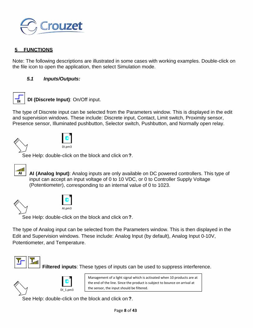
DI (Discrete Input): On/Off input.
The type of Discrete input can be selected from the Parameters window. This is displayed in the edit and supervision windows. These include: Discrete input, Contact, Limit switch, Proximity sensor, Presence sensor, Illuminated pushbutton, Selector switch, Pushbutton, and Normally open relay.
See Help: double-click on the block and click on ?.
AI (Analog Input): Analog inputs are only available on DC powered controllers. This type of input can accept an input voltage of 0 to 10 VDC, or 0 to Controller Supply Voltage (Potentiometer), corresponding to an internal value of 0 to 1023.
See Help: double-click on the block and click on ?.
The type of Analog input can be selected from the Parameters window. This is then displayed in the
Edit and Supervision windows. These include: Analog Input (by default), Analog Input 0-10V,
Potentiometer, and Temperature.
Filtered inputs: These types of inputs can be used to suppress interference.
See Help: double-click on the block and click on ?.
DI.pm3
AI.pm3
DI_1.pm3
Management of a light signal which is activated when 10 products are at
the end of the line. Since the product is subject to bounce on arrival at
the sensor, the input should be filtered.

Page 9 of 43
DO (Discrete output): on/off output.
The type of discrete output can be selected from the Parameters window: Discrete Output, Normally
open relay, Lamp, Solid state relay, Valve, Actuator, Motor, Resistance, Audible signal, Green
indicator light, Red indicator light, Orange indicator light, Indicator light, Heating, Fan.
See Help: double-click on the block and click on ?.
PWM (Pulse Width Modulation) output: PWM outputs are available on controllers with solid
state (transistor) outputs. The value on this type of outputs can vary between 0 and 255.
The frequency for the PWM outputs on the base controller is set during programming by clicking on the
button at the top of the wiring sheet and then going to the Configuration tab. This basic
frequency can be selected from 14 Hz to 1806 Hz.
See Help: double-click on the block and click on ?.
NUM IN, NUM OUT: Used for exchanging 16-bit integers between the controller and
a communication extension.
See Help: double-click on the block and click on ?.
PWM.pm3
DO.pm3

Page 10 of 43
5.2 Control Functions:
Timers: You can select between 5 different types of timer functions.
After you place a timer block on the wiring sheet you can check the External setpoint box, if required:
in this case the time delay setpoints will be integer-type inputs rather than being internal configurable
parameters.
Timer A-C: Applies an ON delay, an OFF delay, or both delays to the output signal in relation to the input signal.
See Help: double-click on the block and click on ?.
BW Timer: Generates a cycle duration pulse on a rising or falling edge or on both edges of an input, according to the setting chosen in the parameters.
See Help: double-click on the block and click on ?.
TIMER_A_C.pm3
In this example you can see how to
create an A-C timer.
Function A-C
Function C
Function A
Input
TON
TOFF
TON
TOFF
TIMER_BW.pm3
This block can be used to convert pushbutton actions into pulses
so they can be counted. If several pushbuttons are connected to
a counter input and a user holds down the pushbutton, pressing
the other pushbuttons would have no effect.

Page 11 of 43
Timer Li/L: Generates pulses when the input is active. It can start in the ON part
of the cycle (Li) or on the OFF part of the cycle (L).
See Help: double-click on the block and click on ?.
Timer B/H: Generates a pulse (the time can be configured) on a rising edge of the input.
See Help: double-click on the block and click on ?.
Totalizer function: It allows to count for how long the input has been held active (or inactive, depending on the mode selected). If the input is in the rest condition then the
timing progress is held. Several types of totalizer modes can be selected from the Parameters window: At, Ht, T,
and Tt.
See Help: double-click on the block and click on ?.
Schmitt Trigger: The output changes state if the input is lower than the minimum value, and
the output changes state again if the input is higher than the maximum value. If the input is between
the two, the output remains unchanged.
See Help: double-click on the block and click on ?.
TIMER_BH.pm3
This example shows how this
timer operates.
TRIGGER.pm3
This is an example of temperature regulation: the
heating comes on when the input is lower than a
certain temperature and goes off when this input
reaches a given temperature.
Stop
Heating
TIMER_Li.pm3
This example shows how to make
an alarm and the display flash.

Page 12 of 43
Bistable: Provides the functionality of an impulse relay. An initial impulse sets the output to 1
then a second impulse is required to change the output back to 0.
See Help: double-click on the block and click on ?.
Set-Reset: Element consisting of two inputs: R for Reset and S for Set. To activate the output,
simply generate a pulse on S; to deactivate it, generate a pulse on R. The priority defines the output
state when both inputs are at 1.
See Help: double-click on the block and click on ?.
1 sec: Internal clock with a period of one second.
See Help: double-click on the block and click on ?.
Comparison of two values: Compares two analog values using the >, ≥, =, ≠, ≤, and <
operators. The output is discrete and it’s activated if the comparison is true.
See Help: double-click on the block and click on ?.
BISTABLE.pm3
On this example the bistable is used to
control lighting.
SetReset.pm3
This is a motor controlled by a Run
button and a Stop button.
1sec.pm3
Flasher
System.
COMPARE.pm3
This program example is used
to activate the output if both
inputs are the same.

Page 13 of 43
Zone comparison: Compares a value between two setpoints (the min and max values delimit
the zone).
See Help: double-click on the block and click on ?.
VAL.pm3
Checking a voltage: If the voltage
is > 6V or < 4V then the bell rings.
Max. limit
Min. limit
Run in the
zone
Stop in the
zone
Input
Output
Page 14 of 43
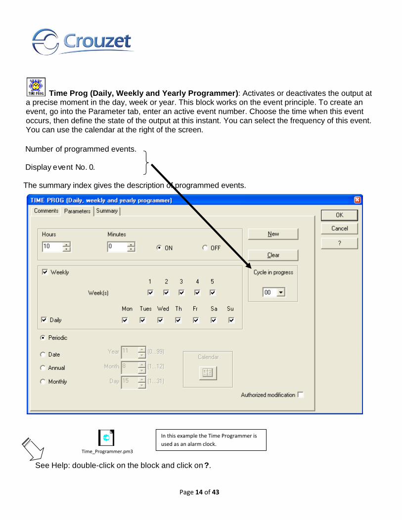
Time Prog (Daily, Weekly and Yearly Programmer): Activates or deactivates the output at a precise moment in the day, week or year. This block works on the event principle. To create an event, go into the Parameter tab, enter an active event number. Choose the time when this event occurs, then define the state of the output at this instant. You can select the frequency of this event. You can use the calendar at the right of the screen.
Number of programmed events.
Display event No. 0.
The summary index gives the description of programmed events.
See Help: double-click on the block and click on ?.
Time_Programmer.pm3
In this example the Time Programmer is
used as an alarm clock.

Page 15 of 43
Counter: Function used for counting up to a value defined in the parameter-setting window. Once this value has been reached, the output changes to 1 until reset if the fixed output is selected or for a certain period if the pulse output is selected. The count value and the maximum value can be displayed. The user has the option of counting from zero to the defined value or from the defined value to zero.
See Help: double-click on the block and click on ?.
Preset Hour Counter: Measures the duration of the input state at 1. After a preset duration,
the output changes state. This block can, for example, be used as an alert on a machine for
maintenance purposes.
See Help: double-click on the block and click on ?.
5.3 HMI/Communication Functions:
Display on the LCD Screen: Displays text or an integer on the LCD screen on the controller
front panel. For example, you can display a decimal derived from an integer. For more details, please
refer to the example.
The Display function is used to display text, variables, and the time and date on the Millenium display.
You can have up to 8 Display blocks active. They are placed on the screen based on the numbering. If
you have more than 8 Display blocks active at the same time only the first 8 blocks will be displayed.
PRESET_COUNT.pm3
Here is a conveyor carrying parts to be packed. After every
5 parts the conveyor stops and the operator packs the
parts. Then he presses the button again to reset the
counter and thus restart the conveyor.
HH_MM.pm3
This is the principle used to warn of
the need for maintenance. Every 30
hours of operation, to change a
filter on the machine, for example.

Page 16 of 43
The function window is used for displaying the variable with decimal places and for editing the text.
In this example 4 display blocks are used:
Here B00 is selected, which displays the content of the variable B01;
Here a display of 1/10000 has been chosen by selecting this radio button.
You can place the text or data on the exact position that you require just by clicking on that position on the grid.
Note: Calibration compensates for drifting of the Millenium clock. If the calibration button is activated
the display will allow modification of this value. The unit is in seconds per week.
See Help: double-click on the block and click on ?.
LCD.pm3
This is an example of using the controller’s LCD
display. The date, time, text and a decimal value(
from an integer) are displayed on it.

Page 17 of 43
TEXT function: Displays text and/or numerical values on the LCD screen on the controller’s
front panel. You can connect up to 4 numerical values to the same block and locate them, along with
text, on the screen. You can also display the date and time and the calibration value for the clock drift.
This function doesn’t allow for any special formatting on the numerical values. If that is required then
the Display block has to be used.
You can only have one Text block active at the same time, since it covers the entire screen. If you
have more than one active only the block with the highest number will be displayed.
See Help: double-click on the block and click on ?.
LCD backlighting: This block is processed like an output. When it is active it activates the
backlighting of the display
See Help: double-click on the block and click on ?.
Buttons: You can use the buttons on the front panel of the Millenium in your application: A, B, ESC, OK, + and -.
See Help: double-click on the block and click on ?.
ABEscOK.pm3
This example shows how to
use the front panel keys on a
program.
TEXT.pm3
Example of use of the Text function. The date,
time, text, and a couple of numerical values are
displayed on two different screens.
Page 18 of 43
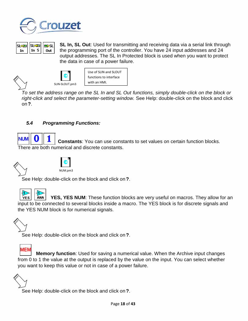
SL In, SL Out: Used for transmitting and receiving data via a serial link through the programming port of the controller. You have 24 input addresses and 24 output addresses. The SL In Protected block is used when you want to protect the data in case of a power failure.
To set the address range on the SL In and SL Out functions, simply double-click on the block or right-click and select the parameter-setting window. See Help: double-click on the block and click on ?.
5.4 Programming Functions:
Constants: You can use constants to set values on certain function blocks.
There are both numerical and discrete constants.
See Help: double-click on the block and click on ?.
YES, YES NUM: These function blocks are very useful on macros. They allow for an
input to be connected to several blocks inside a macro. The YES block is for discrete signals and
the YES NUM block is for numerical signals.
See Help: double-click on the block and click on ?.
Memory function: Used for saving a numerical value. When the Archive input changes
from 0 to 1 the value at the output is replaced by the value on the input. You can select whether
you want to keep this value or not in case of a power failure.
See Help: double-click on the block and click on ?.
NUM.pm3
SLIN-SLOUT.pm3
Use of SLIN and SLOUT
functions to interface
with an HMI.

Page 19 of 43
5.5 Calculation Functions:
Gain: Allows the use of a scale factor and is applicable to all analog data.
Example: This is a program which uses a counter, a comparator, a gain and the counter read-out display. An alarm is activated after the sensor has been passed 20 times.
See Help: double-click on the block and click on ?.
Example of a gain function used for displaying the temperature measured by a PT 100 temperature probe between -20 and + 60°:
The measurement scale A = 80 (-20 to +60); these 80°C are divided into 1024 points. The offset corresponds to -20°C; the limit display values would be 60 and -20.
This example combines some blocks that have already been introduced in order to control temperature and display it on the screen. The Gain function is used to convert the data provided by the sensor into a more useful format.
GAIN.pm3
In this example, an alarm is
activated after the sensor has been
passed 20 times. The number of
impulses is divided by 5.
Range: 800
Resolution: 0 to 1023
Min. Value: -200
Max. Temp: 60.0 °C
Min. Temp: -20.0 °C

Page 20 of 43
In this example, the chosen display is 1/100°C and therefore all the parameters of the Schmitt Trigger function and the Gain function should be multiplied by 100 with the exception of the 1023 denominator constant.
Arithmetic functions: Perform arithmetic operations on numerical integers. You can do additions, subtractions, multiplications and divisions.
If an input is not connected it is set to 0 (ADD-SUB) or to 1 (MUL-DIV).
See Help: double-click on the block and click on ?.
Word-Bit conversions: Allow to break down an integer into individual bits or to take the individual bits and form an integer with them. Each integer consists of 16 bits.
These function blocks are especially useful when there is communication (Modbus, Serial Link)
involved in the application since the data exchanged are words and sometimes you need to address
individual bits.
See Help: double-click on the block and click on ?.
GAIN_1.pm3

Page 21 of 43
5.6 Logic Functions:
Logic Gates:
Logic gates can be used to construct logic (combinational) circuits.
The available functions are NOT, AND, OR, NAND, NOR, and XOR. They are available on 2, 4 and 6
input versions, depending on the function. Only the inputs connected are taken into account.
See Help: double-click on the block and click on ?.
Boolean functions: On these functions the output(s) react(s) according to the truth
table described in the parameters. There is one version with 4 inputs and 1 output and another
version with 6 inputs and 2 outputs. Only the inputs connected are taken into account.
See Help: double-click on the block and click on ?.
5.7 SFC/Grafcet Functions:
SFC functions are similar to Grafcet language. The principle is simple, since it involves sequential
programming, with steps succeeding one another surrounded by transitions. When a step is active,
wait for the next transition to become active in order to go to the next step.
See Help: double-click on the block and click on ?.
BOOLEAN.pm3
SFC.pm3
This example shows the
sequence of a program
using SFC functions.

Page 22 of 43
6 STARTING AN APPLICATION
6.1 The Edit window
Select New File and click the type of Millenium that you have chosen. Select the part number corresponding to the controller.
The edit window opens with a blank wiring sheet and you are ready to build your application. The part number of the selected Millenium controller then appears at the top of the wiring sheet. Blocks are positioned by clicking on the block, holding down and dragging it onto the programming page. Links between blocks are created directly by selecting block inputs and outputs. In the wiring mode tool, you can choose wire as the wiring type, and you will see the links between the various elements. If you choose text mode, the links will be marked but they will no longer be visible.

Page 23 of 43
To change this parameter, right-click on a link and select the wiring type: wire or text.
Example of wiring:
You can choose the text to place for each connection. Just position the cursor on the desired connection, right-click with the mouse, choose Type of Wiring and Modify the text.

Page 24 of 43
When you want to move an input or output which is
already assigned to an element you can move it by
using the handle on the side.
It is possible to change an input or output type. This option does not affect operation.
If you want to change an input or output type, simply double-click on the icon and choose an alias. On the wiring page, you can add a comment and drawings. To do this, you can use the draw toolbar and also the draw menu bar. To change the line thickness, the line color or the background color, you need to select the element
and click on the icon associated with the desired action in the toolbar.
6.2 Editing your program: Edit mode
At the top of the wiring page you can see these three buttons.
Displays the selected millennium 3
By clicking title Author, you can write in the project name, date and author. By clicking Program, you can select the application cycle duration (10ms by default).
Then you can choose the date format.
If you are using PWM outputs, you can select the frequency of all the PWM outputs (by default
1806.37 Hz).
To build your application:
Select the input blocks and place them on the input terminals, select the output blocks and place them on the output terminals. Select the function blocks, create the wiring between the various points. Double-click on the functions
in order to set the parameters.
Each function block is numbered in the order of placing the blocks on the programming page. Deleting
blocks results in a break in the numbering. To renumber, select the blocks then Tools, Renumber
functions.
In text mode wiring, each link is numbered in the order of placing the wiring on the wiring page.
Deleting links results in a break in the numbering. To renumber, select the links then Tools,
Renumber links.
By selecting a number of blocks, you can align them according to the icon on the Draw bar. Align left, right, center, etc.
Page 25 of 43
6.2.1 Supervision
Select window then Supervision. Simply drag the inputs/outputs and function blocks of your choice from the wiring page to the supervision window. You can illustrate your application using the draw tools. You can also choose a .BMP background image by right-clicking in the supervision window; Modify background, Bitmap. This window explicitly displays the elements you have dragged from the wiring page in their own
environment. When you change to simulation or monitoring mode, the inputs and the outputs are
updated; it is also possible to force an input in the same way as with the edit window. Here is an
example of using supervision mode:
6.2.2 Import
You have the option of recovering all or part of the programming page of an existing file. To import a wiring
scheme, you should already have opened a file. First select File, then Import. Next choose the file to be
imported. When importing a wiring scheme, you will see that the previously opened file stays open. You
can therefore drag a selection from the edit window of the imported wiring scheme to the edit window of
the previous wiring scheme.
6.3 Testing your program: Simulation mode
Our software also lets you fully test your program before implementing it. Simply select S or simulation
mode. Simulation on discrete or analog inputs can be temporary or permanent. Force the input or
output by clicking on the link or on the input or output pin. It is not necessary for the controller to be
connected to the PC to perform simulation.
6.3.1 Front panel display
In simulation mode, click on Window then on Front Panel. The keys illustrated on the front panel are
activated by clicking and holding down.
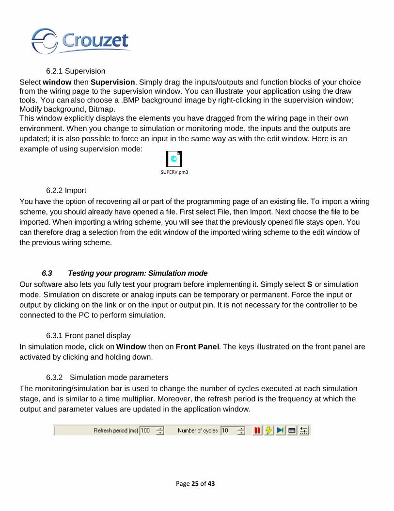
6.3.2 Simulation mode parameters
The monitoring/simulation bar is used to change the number of cycles executed at each simulation
stage, and is similar to a time multiplier. Moreover, the refresh period is the frequency at which the
output and parameter values are updated in the application window.
SUPERV.pm3

Page 26 of 43
6.4 Writing to the controller and running
Once your application has been debugged and verified, you can transfer it to the Millenium controller.
The Write to the controller function translates the program into data that can be loaded into the
controller and transfers it from the PC to the controller.
To write data to the controller, it must be in STOP mode. After the program has been stopped go into
the Controller menu, click on Write to the controller.
This option will open the Compilation Results window. If the compilation is successful then following
windows appears:
6.5 Monitoring mode
In Monitoring mode the controller has to be connected to the PC. This mode has the same
characteristics as in the simulation mode. The state of any Millenium inputs and outputs can be
displayed or changed from the software workshop. These inputs are visible from the edit window and
the supervision window. The front panel is used to monitor the process and operate the keys remotely
by selecting the front panel window.

Page 27 of 43
6.6 Printing your application
You can print a complete application listing. Printing an application provides full documentation for the
application. It consists of:
A wiring diagram for the application,
Wiring diagram(s) of macro(s),
The content of the Supervision window,
A table with the following for each symbol:
o A representation of the symbol,
o Its block number,
o The associated comment,
o The parameters with their values and their descriptions
Select File, Printer setup. Select the required parameters. Before printing, select File, Print preview

Page 28 of 43
7 MILLENIUM IN RUN MODE
7.1 The display
This is the default screen for a Millenium without extension:
If no Display function is used, the Millenium displays the state of the inputs, the outputs, the time, and
the diagnostic icons.
7.2 Accessing the menu
If the front panel lock option has not been activated, you access the menu by pressing ESC or OK.
If there is a display function in your program, to go to the menu you should press ESC and OK at the
same time.
7.3 Menu structure
These are the main menus:
or

Page 29 of 43
7.4 Run/Stop
Access the menu by pressing ESC or OK. If the Millenium is in RUN mode, the icon turns and the
menu says STOP. If the Millenium is stopped, the icon is steady and the menu says RUN.
If you select RESET LATCHED VALUES & RUN on the RUN sub-menu then the values of the function blocks for which the Save on power failure option was checked will be reset.
7.4.1 Accessing the menu with a password
If the program on the controller is password protected the key icon ( ) is displayed.
To access the menu you have to enter the password, using the + and – buttons. For example, if you
want to enter the password 1250, hold down the + button and scroll rapidly until the value is
approached, then release the button and scroll slowly, pressing repeatedly until you reach 1250. Then press OK.
You can make 5 attempts to enter the password. If you fail to enter your password correctly after 5 attempts, you can try again after 30 minutes.
7.5 Setting the date and time
To ensure that the programs work correctly with time-based programming, the date and the time must
be set accurately. The modifiable parameters are:
Day / Month / Year
Hours, Minutes, Seconds
Controller clock drift, in seconds per week
7.5.1 Setting the time on the Millenium from the software workshop
From the software workshop: Go to the Controller menu and you can then select Read/Write date and
time. You are then presented with the following dialogue box:
The controller’s time is displayed by default. You can modify this time if needed and then write it into
the controller.

Page 30 of 43
7.5.2 Setting the time on the Millenium from the front panel
First, go into the main menu. To do this, press OK or
ESC. If the password is required, enter it. The
following menu should appear:
Press - twice until MISCELLANEOUS becomes the
item that flashes. Press OK. The following menu
should appear:
Now, scroll down to CLOCK, which flashes, and press
OK. The following menu should appear:
Press OK and the following screen should appear:
To select a value to modify, you can browse using the + and – keys. To modify a value, select it then
press OK. You can then modify the value by pressing the + and + keys and finally confirm by pressing
OK.
7.5.3 Calibration
Calibration compensates for clock drift. The unit is in seconds per week. To modify this value, go into
the time setting menu then select the calibration value. To modify it, press OK, then to change the
value press the + or – keys and confirm with OK.
7.6 Values in the blocks which can be modified
It is possible to modify block parameters such as numerical constants, counters, timers, gain blocks,
time programmers, etc. directly from the controller’s front panel in two ways: by selecting the function
block, or via the Display and Text functions.
Important: Make sure that the type of Millenium selected in the workshop is the same as the one you are using. Check this by clicking on Tools then Choose the type of controller.
Click on Controller then on Write to the controller to modify the parameters. Click Run.
EX.pm3

Page 31 of 43
7.7 Modifying a value by selecting FBD blocks
To go into the configuration menu press OK or ESC. Once in the menu, select PARAMETERS. To do this, press the – key until PARAMETERS is the flashing item. This screen will then appear:
Now press OK to confirm. The black text flashes indicating that a value has been selected. To modify it, press OK.
The value flashes when modification is possible. The OK key will switch from one mode to the other.
Note: NO PARAMETER means that there are no blocks with configurable parameters.
In this example, the FBD number is B03. You should select 003. If you wish to select another configurable block, press +. When the required number is reached, confirm with the OK button.
To browse the various parameters, select the type of parameter by pressing to obtain the parameters.
Then press OK.
In this example, time delay B function is selected and the only parameter is the time delay duration
Select a new value and confirm with OK (enter a value of your choice and confirm with OK). If your
program is running, you will see the change.

Page 32 of 43
7.8 Modifying a variable using Display or Text blocks.
In this case, the variables to be modified should be wired to the analog input(s) of the function block.
When the Authorized modification box is checked it is possible to modify the value.
Continuous flashing indicates the value (or one of the values) that can be modified.
Select the value to be modified with the + and - keys; then OK.
To modify the value press the + and - keys again. Then confirm
with OK.
Page 33 of 43
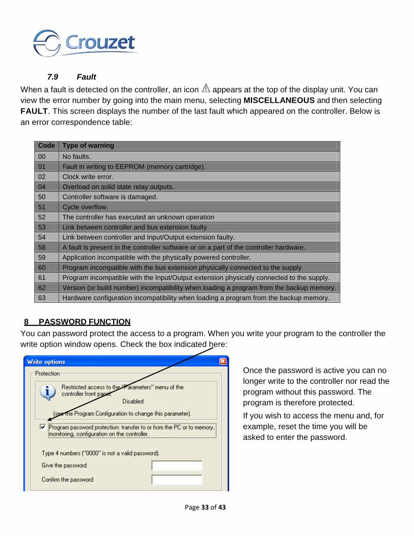
7.9 Fault
When a fault is detected on the controller, an icon appears at the top of the display unit. You can
view the error number by going into the main menu, selecting MISCELLANEOUS and then selecting
FAULT. This screen displays the number of the last fault which appeared on the controller. Below is
an error correspondence table:
Code Type of warning
00 No faults.
01 Fault in writing to EEPROM (memory cartridge).
02 Clock write error.
04 Overload on solid state relay outputs.
50 Controller software is damaged.
51 Cycle overflow.
52 The controller has executed an unknown operation
53 Link between controller and bus extension faulty
54 Link between controller and Input/Output extension faulty.
58 A fault is present in the controller software or on a part of the controller hardware.
59 Application incompatible with the physically powered controller.
60 Program incompatible with the bus extension physically connected to the supply
61 Program incompatible with the Input/Output extension physically connected to the supply.
62 Version (or build number) incompatibility when loading a program from the backup memory.
63 Hardware configuration incompatibility when loading a program from the backup memory.
8 PASSWORD FUNCTION
You can password protect the access to a program. When you write your program to the controller the
write option window opens. Check the box indicated here:
Once the password is active you can no
longer write to the controller nor read the
program without this password. The
program is therefore protected.
If you wish to access the menu and, for
example, reset the time you will be
asked to enter the password.

Page 34 of 43
8.1 You have lost your password
If the password is lost, the only solution is to delete the program from the controller. To do this, go into the controller menu then select delete the controller content. It will then be possible to write a new program to the controller.
9 FRONT PANEL LOCK
The front panel lock function prevents any access to the menus. The lock is effective when the program is running, but also when it is stopped. To start or stop the program once the lock is active, you have to go via the software workshop. However, the front panel lock does not prevent use of the front panel buttons in a program.
To activate the front panel lock go to the Program configuration tab and check the option “Restricted access to the „Parameters‟ menu of the controller front panel”.
When you write to the controller this option will be applied to your controller.
9.1 Unlocking the front panel
To unlock the front panel, uncheck the “Restricted access to the „Parameters‟ menu of the controller front panel” option and rewrite the program to the controller.
10 MEMORY MODULE
The memory module 88 970 109 can be used to backup a program. The Millenium can both write
and read a program from the cartridge.
10.1 Saving a controller program to the module
Insert the memory module into the Millenium with the front panel unlocked. Saves are performed in
STOP mode.
Save procedure:
Go into the main menu by pressing the ESC key. Select MEMORY CARD. You will have two
Save options available:
o Save without front panel lock (SAVE),
o Save with front panel lock (SAVE & LOCK KEYPAD).
Page 35 of 43
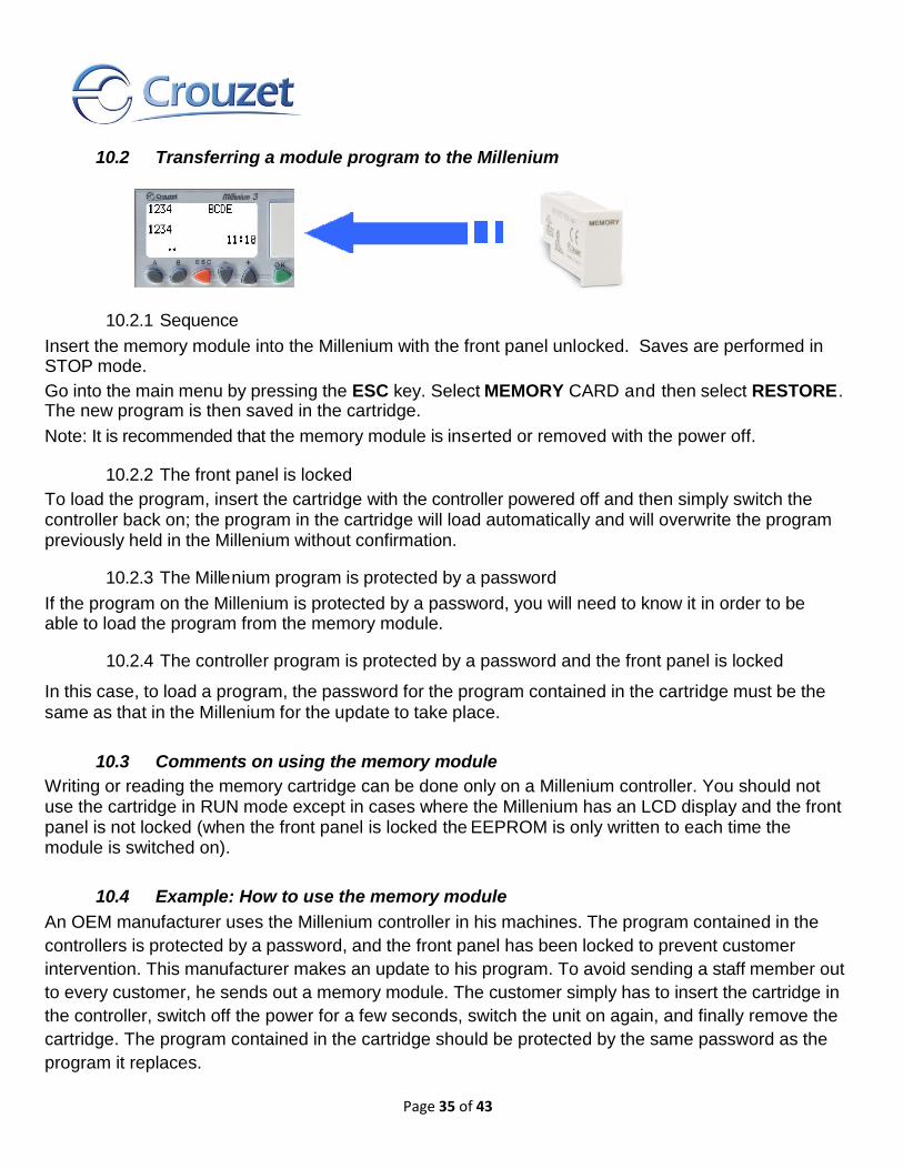
10.2 Transferring a module program to the Millenium
10.2.1 Sequence
Insert the memory module into the Millenium with the front panel unlocked. Saves are performed in STOP mode.
Go into the main menu by pressing the ESC key. Select MEMORY CARD and then select RESTORE. The new program is then saved in the cartridge.
Note: It is recommended that the memory module is inserted or removed with the power off.
10.2.2 The front panel is locked
To load the program, insert the cartridge with the controller powered off and then simply switch the controller back on; the program in the cartridge will load automatically and will overwrite the program previously held in the Millenium without confirmation.
10.2.3 The Millenium program is protected by a password
If the program on the Millenium is protected by a password, you will need to know it in order to be able to load the program from the memory module.
10.2.4 The controller program is protected by a password and the front panel is locked
In this case, to load a program, the password for the program contained in the cartridge must be the
same as that in the Millenium for the update to take place.
10.3 Comments on using the memory module
Writing or reading the memory cartridge can be done only on a Millenium controller. You should not use the cartridge in RUN mode except in cases where the Millenium has an LCD display and the front panel is not locked (when the front panel is locked the EEPROM is only written to each time the module is switched on).
10.4 Example: How to use the memory module
An OEM manufacturer uses the Millenium controller in his machines. The program contained in the
controllers is protected by a password, and the front panel has been locked to prevent customer
intervention. This manufacturer makes an update to his program. To avoid sending a staff member out
to every customer, he sends out a memory module. The customer simply has to insert the cartridge in
the controller, switch off the power for a few seconds, switch the unit on again, and finally remove the
cartridge. The program contained in the cartridge should be protected by the same password as the
program it replaces.

Page 36 of 43
11 APPLICATION-SPECIFIC FUNCTIONS
Application-specific functions are special function blocks developed to solve common application problems. Some of these functions are only available on controllers of the SMART range (the icons are marked with a C on the corner).
11.1 Application-specific functions in the software workshop
Most of the Application-specific functions are found in the function bar in the APP tab.
See description in the window for each function by clicking Help ?.
You can put several application-specific functions in the wiring page. You can also place the same
application-specific function in several times.
11.2 Application-specific functions in the Millenium
The Millenium can only hold a limited number of application-specific function slots. When loading a program which contains 1 or more application-specific functions, you can find out the Millenium’s availability by pointing the cursor here. Availability is expressed in slots (44 or 76 in total).
FBD_C.pm3

Page 37 of 43
Note: The number of application-specific function blocks used in the application is not linked to the
number of slots available in the Millenium.
11.3 Made-to-order application-specific functions
To resolve an specific application problem please consult us for help in designing your application- specific function.
12 COMMUNICATION OPTIONS
12.1 Communication via Modbus Extension
The Modbus protocol is a master/slave protocol that allows one, and only one, master to request responses from slaves, or to act based on the request.
To use Modbus functions, a Modbus XN03 or XN06 extension must be added to an expandable controller (XD10, XD26, XB10, or XB26).
Modbus communication can be used in Ladder language and in FBD language.
Note: The Modbus extensions can only operate in Modbus slave mode.
12.1.1 Functional description
The Modbus extension has the following features:
Connection on a Modbus network: 2 or 4-wire
Maximum network length: 1000 meters (9600 bauds)
Line terminated at both ends (Line terminators: 1nF, 10V, 120 ohms, 0.25 W in series)
Polarized line (Pull Up/Down: 470 ohms/0.25W polarization resistor)
Use of a shielded cable
Male RJ45 connectors
COMMON signal connected directly to the protection ground and to a point on the bus
12.1.2 Parameters setting
The Modbus properties of the extension module can be configured in the software workshop by
clicking on Files, then on Properties and then going to the Modbus sandwich extension tab.
You can also get to this window by clicking on the name of the extension module at the top of the
wiring sheet.

Page 38 of 43
These are the available parameters:
Number of wires and format:
o 2-wire, RTU
o 4-wire, RTU
o 2-wire, ASCII
o 4-wire, ASCII
Speed in bauds:
o Transmission speed (bauds): 1200, 2400, 4800, 9600, 19200, 28800, 38400 and 57600.
Parity:
o None
o Even
o Odd
Modbus slave address:
o Network address: 1 to 247
12.1.3 Data exchange
Depending on the extension module selected you have 8 or 16 16-bit data exchange words, four clock
words and one status word.
These extensions support four Modbus functions: Read multiple registers, Write single register, Write
multiple registers, and Read device identification.
Here you can see an example program using the XN06 Modbus extension:
For additional information please refer to the M3 Software Help files and to the installation sheets for
these extension modules.
12.2 Communication via Ethernet Extension
Using the XN05 extension module you can communicate using the Modbus over Ethernet (Modbus TCP/IP) protocol. Modbus TCP/IP is based on a client/server model. Each Modbus server has an array of registers where clients can read or write data.
The XN05 extension can only be used with an expandable controller (XD10, XD26, XB10, or XB26). This extension works as a server on a network; it can only respond to messages that are sent to it.
Ethernet communication can be used in FBD language only.
MODBUS.pm3

Page 39 of 43
12.2.1 Features
The Ethernet extension has an RJ45 female connector and two LEDs that provide the status of the
communication: LK/ACT 10/100 and STS.
12.2.2 Parameters setting
The properties of the Ethernet extension module can be configured in the software workshop by
clicking on Files, then on Properties and then going to the Sandwich Ethernet Extension tab.
You can also get to this window by clicking on the name of the extension module at the top of the
wiring sheet.
These are the available parameters:
IP Address Acquisition Mode:
o Dynamic
o Static
In case Static mode was selected:
o IP address
o Sub-network mask
o Gateway address
Reserved address (in case the Ethernet extension needs to be constantly connected to a client)
Timeout period
T
12.2.3 Data exchange
The Ethernet extension can exchange 16 data words, 4 clock words and one status word with the
Modbus TCP/IP client.
This extension supports four Modbus functions: Read multiple registers, Write single register, Write
multiple registers, and Read device identification.
For additional information please refer to the M3 Software Help files and to the installation sheet for
this extension module.
12.3 Modem Communications
The M3MOD module can be used to interface the Millenium with 2 types of modems: Landline (PSTN) and GSM modems.
Depending on the type of modem used you have the following functions:
Send alarms/receive instructions from cell phone
Send alarms/receive instructions from PC running “M3 Alarm” software

Page 40 of 43
Transfer program, Update firmware, or go into Monitoring mode
Send alarm to e-mail address
For additional information please refer to the M3 Software Help files and to the installation sheet for the
M3MOD module.
13 Example of an FBD Application
This example describes how a greenhouse's window panes can be managed automatically.
13.1 Specifications
The owner of a greenhouse would like to automate the opening and closing of the ventilation window
panes located on the greenhouse roof.
The greenhouse has two window panes to provide ventilation. The opening of these window panes is
controlled by a motor and by 2 sensors that indicate whether the window panes are open or closed:
During the day, the window panes open to ventilate the structure from 12:00 to 15:00, at the time of
day when, in principle, the temperature is the highest. However, if the temperature is less than 10ºC,
he window panes do not open, or when they are already open, they close.
In addition, the window panes open during the day when the temperature reaches 25ºC. If the
temperature falls below 25 ºC, the window panes must close again.
Finally, at night, the window panes remain closed regardless of the temperature.
13.2 Program description
3 time ranges are used:
Range 1: Night, from 21:00 to 07:00
Range 2: Day, from 07:00 to 12:00 and from 15:00 to 21:00
Range 3: Noon, from 12:00 to 15:00
13.3 Summary
Input/Output Tables
Description of the inputs:
Input Description
I1 Window Panes Open (Discrete)
I2 Window Panes Closed (Discrete)
IB Temperature (Analog)

Page 41 of 43
Description of the outputs:
Input Description
O1 Opening of the Window panes (Discrete)
O2 Closing of the Window panes (Discrete)
Model required:
For this application a controller with analog inputs is required so a DC powered controller will be
selected. For this example we choose a CD12 Smart 24VDC, Solid State Ouput (P/N 88 974 042).
FBD wiring sheet:
GREENHOUSE.pm3

Page 42 of 43
Description of the Parameters:
Daily Programmer B05
Cycle in progress: 00
Hour: 12, Minute: 0
Output: ON
Weekly and Daily are checked
Cycle in progress: 01
Hour: 15, Minute: 0
Output: OFF
Weekly and Daily are checked
Daily Programmer B06
Cycle in progress: 00
Hour: 21, Minute: 0
Output: ON
Weekly and Daily are checked
Cycle in progress: 01
Hour: 7, Minute: 0
Output: OFF
Weekly and Daily are checked
Analog comparator B07
Value 1 < Value 2
Analog comparator B08
Value 1 >= Value 2
GAIN Block B09
A = 1500, B = 1023, C = -100
Range: -32768 to 32767
Page 43 of 43
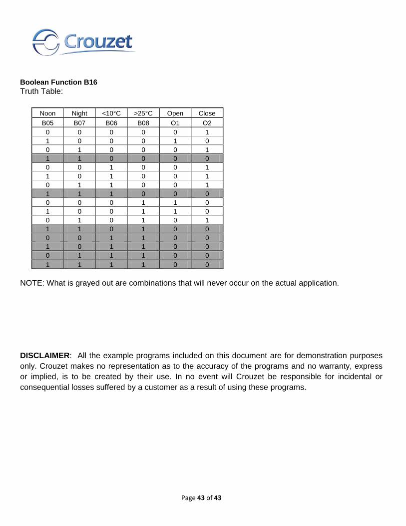
Boolean Function B16
Truth Table:
Noon Night <10°C >25°C Open Close
B05 B07 B06 B08 O1 O2
0 0 0 0 0 1
1 0 0 0 1 0
0 1 0 0 0 1
1 1 0 0 0 0
0 0 1 0 0 1
1 0 1 0 0 1
0 1 1 0 0 1
1 1 1 0 0 0
0 0 0 1 1 0
1 0 0 1 1 0
0 1 0 1 0 1
1 1 0 1 0 0
0 0 1 1 0 0
1 0 1 1 0 0
0 1 1 1 0 0
1 1 1 1 0 0
NOTE: What is grayed out are combinations that will never occur on the actual application.
DISCLAIMER: All the example programs included on this document are for demonstration purposes
only. Crouzet makes no representation as to the accuracy of the programs and no warranty, express
or implied, is to be created by their use. In no event will Crouzet be responsible for incidental or
consequential losses suffered by a customer as a result of using these programs.