m-series® m2000 - instrumart · pdf filem-series® m2000, hart® bi-directional...
TRANSCRIPT

M-Series® M2000HART® Bi-Directional Communication Protocol Data Access
MAG-UM-01408-EN-03 (February 2015) User Manual

M-Series® M2000, HART® Bi-Directional Communication Protocol Data Access
Page ii February 2015MAG-UM-01408-EN-03

CONTENTS
About This Manual . . . . . . . . . . . . . . . . . . . . . . . . . . . . . . . . . . . . . . . . . . . . . . . . . . . . . . . . . . . . . . . . . . . . . . 5
Definitions . . . . . . . . . . . . . . . . . . . . . . . . . . . . . . . . . . . . . . . . . . . . . . . . . . . . . . . . . . . . . . . . . . . . . . . . 5
Scope . . . . . . . . . . . . . . . . . . . . . . . . . . . . . . . . . . . . . . . . . . . . . . . . . . . . . . . . . . . . . . . . . . . . . . . . . . . 5
Introduction . . . . . . . . . . . . . . . . . . . . . . . . . . . . . . . . . . . . . . . . . . . . . . . . . . . . . . . . . . . . . . . . . . . . . . . . . . 5
Installation . . . . . . . . . . . . . . . . . . . . . . . . . . . . . . . . . . . . . . . . . . . . . . . . . . . . . . . . . . . . . . . . . . . . . . . . . . . 6
Prerequisites . . . . . . . . . . . . . . . . . . . . . . . . . . . . . . . . . . . . . . . . . . . . . . . . . . . . . . . . . . . . . . . . . . . . . . . 6
Installing the Daughterboard . . . . . . . . . . . . . . . . . . . . . . . . . . . . . . . . . . . . . . . . . . . . . . . . . . . . . . . . . . . . 6
M2000 and HART . . . . . . . . . . . . . . . . . . . . . . . . . . . . . . . . . . . . . . . . . . . . . . . . . . . . . . . . . . . . . . . . . . . . . . 8
Device Variables . . . . . . . . . . . . . . . . . . . . . . . . . . . . . . . . . . . . . . . . . . . . . . . . . . . . . . . . . . . . . . . . . . . . 9
Dynamic Variables . . . . . . . . . . . . . . . . . . . . . . . . . . . . . . . . . . . . . . . . . . . . . . . . . . . . . . . . . . . . . . . . . . . 9
Device Status . . . . . . . . . . . . . . . . . . . . . . . . . . . . . . . . . . . . . . . . . . . . . . . . . . . . . . . . . . . . . . . . . . . . . . 9
Meter Status Register . . . . . . . . . . . . . . . . . . . . . . . . . . . . . . . . . . . . . . . . . . . . . . . . . . . . . . . . . . . . . . . . 10
Universal Command #0 – Read Unique Identifier . . . . . . . . . . . . . . . . . . . . . . . . . . . . . . . . . . . . . . . . . . . . . . 10
Universal Command #9 – Read Device Variables with Status . . . . . . . . . . . . . . . . . . . . . . . . . . . . . . . . . . . . . . . 10
Universal Command #48 – Read Additional Device Status . . . . . . . . . . . . . . . . . . . . . . . . . . . . . . . . . . . . . . . . . 11
Additional Features . . . . . . . . . . . . . . . . . . . . . . . . . . . . . . . . . . . . . . . . . . . . . . . . . . . . . . . . . . . . . . . . . . . . 12
Security . . . . . . . . . . . . . . . . . . . . . . . . . . . . . . . . . . . . . . . . . . . . . . . . . . . . . . . . . . . . . . . . . . . . . . . . . 12
Fixed Current Mode (Multi-Drop) . . . . . . . . . . . . . . . . . . . . . . . . . . . . . . . . . . . . . . . . . . . . . . . . . . . . . . . . . 13
Command Action Request . . . . . . . . . . . . . . . . . . . . . . . . . . . . . . . . . . . . . . . . . . . . . . . . . . . . . . . . . . . . . 14
Empty Pipe Calibration . . . . . . . . . . . . . . . . . . . . . . . . . . . . . . . . . . . . . . . . . . . . . . . . . . . . . . . . . . . . . . . 14
Analog Output Calibration . . . . . . . . . . . . . . . . . . . . . . . . . . . . . . . . . . . . . . . . . . . . . . . . . . . . . . . . . . . . . 15
Data Management . . . . . . . . . . . . . . . . . . . . . . . . . . . . . . . . . . . . . . . . . . . . . . . . . . . . . . . . . . . . . . . . . . . . . 16
Device Description . . . . . . . . . . . . . . . . . . . . . . . . . . . . . . . . . . . . . . . . . . . . . . . . . . . . . . . . . . . . . . . . . . . . 21
Troubleshooting . . . . . . . . . . . . . . . . . . . . . . . . . . . . . . . . . . . . . . . . . . . . . . . . . . . . . . . . . . . . . . . . . . . . . . 21
Compliance . . . . . . . . . . . . . . . . . . . . . . . . . . . . . . . . . . . . . . . . . . . . . . . . . . . . . . . . . . . . . . . . . . . . . . . . . 22
User Manual
Page iii February 2015 MAG-UM-01408-EN-03

M-Series® M2000, HART® Bi-Directional Communication Protocol Data Access
Page iv February 2015MAG-UM-01408-EN-03

ABOUT THIS MANUAL
Definitions
DD Device Description
HART Highway Addressable Remote Transducer
HOST Host System, typically the master (i .e . handheld device)
PV Primary Variable
SV Secondary Variable
TV Tertiary Variable
FV Fourth Variable
ScopeThis document discusses the supported features of HART and how these features are related to the M2000 . This document also discusses special considerations and the type of data that is accessible over HART . This document is intended for readers who have a general understanding of the HART protocol . For further information regarding the HART protocol please refer to www.hartcomm.org .The M2000 HART daughterboard supports Universal Command Revision 7 .
INTRODUCTIONHART protocol provides the means for sending and receiving digital information across analog wires . HART is a bi-directional communication protocol that provides data access between intelligent field instruments (like the M2000) and host systems (like the Emerson Field Communicator) . HART technology is a master/slave protocol, which means that a field device only speaks when spoken to by a master . The M2000 operates as a slave device . In order to connect with the M2000 using the HART protocol, the HART daughterboard is required . As an accessory module to the M-Series M2000, the HART daughterboard allows access to many of the M2000 measurements and configuration data using the analog wires . In addition, the HART daughterboard allows for real-time control and monitoring of the M2000 .The Device Description (DD) files for the M2000 are located on www.hartcomm.org under Product Catalog > All Products > M2000 . These files describe the supported features and functions of the M2000 with respect to HART . The DD includes details of menus and graphic display features to be used by host applications in order to access all parameters and data in the M2000 . These files describe what parameters are accessible and should be installed in host systems . In order to provide access to the M2000 over HART, the daughterboard converts HART protocol commands to MODBUS™ RTU commands .
M2000DSP
HARTDaughter
Board
Modbus RTU HART
INTELLIGENTHOST
Figure 1: HART-to-MODBUS RTU Commands
About This Manual
Page 5 February 2015 MAG-UM-01408-EN-03

INSTALLATION
PrerequisitesInstalling a HART daughterboard into an M2000 has two requirements:
• Firmware v1 .10 or later .
• M2000 PCB serial number must indicate that the board was manufactured week 19 of Year 2011 or later .
The PCB serial number is listed in the menus at Main Menu > Info/Help > Serial Number .The PCB serial number is of the following format: WWYYSSSS, where WW = Week, YY = Year .A label on the main board also indicates the week and year .
Figure 2: Main Board Label
Installing the DaughterboardThe daughterboard connects to the 11-pin connector labeled as COMMUNICATION on the main amplifier .
Figure 3: Daughterboard Connection
Installation
Page 6 February 2015MAG-UM-01408-EN-03

Follow these steps to install the daughterboard:1 . Prior to installing the daughterboard, verify or configure the M2000 Communication Port B . Access the port settings at
Main Menu > Communications > Port B Settings .
Parameter Value CommentsPort Address 001 —
Extended Port Address — Not applicable for HARTBaud Rate 38400 HART Daughterboard auto-bauds, all baud rates supportedData Bits 8 —
Parity EVEN —Stop Bits 1 —
2 . Verify or configure the analog output range at 4…20 mA . Access the analog output range at Main Menu > Inputs/Outputs > Analog Output Range .
3 . Power off the M2000 .
DISCONNECT THE INPUT POWER BEFORE ACCESSING THE EQUIPMENT. This step is important for the M2000 to properly recognize the HART daughterboard and fulfill HART compliance .
4 . Prior to inserting the daughterboard, install the foam insulation pad as shown below . Be sure to align the groove with the two screws attaching the detector or wall mount bracket to the enclosure . The primary purpose of this pad is to ensure the daughterboard is insulated from the enclosure wall . It is important to install this pad flush with the top of the enclosure wall .
Figure 4: Installing Foam Insulation Pad
5 . Insert the daughterboard into the 11-pin connector .6 . Use the following information to make appropriate wiring of analog wires to the 4-pin customer connector .
Pin Number Pin Description Comments41 Analog Ground —42 Analog Signal Requires minimum loop impedance of 230 Ω for communication43 Analog Shield Only for shielded wires44 Chassis Jumper Connect to screw in corner
7 . Power on the M2000 .8 . Allow time for the daughterboard to properly power up and be recognized by the M2000 before navigating the menus .
This time is typically 5 seconds . If the HART daughterboard is not recognized, then the M2000 should be power cycled .9 . Verify recognition of the HART daughterboard . Navigate to Main Menu > Info > Help . The Daughterboard Info field indicates
the Daughterboard Type is HART .
Apply insulation pad flush with the top of
the housing .
Installation
Page 7 February 2015 MAG-UM-01408-EN-03

M2000 AND HARTHART protocol has three categories of commands: Universal, Device-Specific and Common Practice . The M2000 HART daughterboard supports only some Universal commands and Device-Specific commands . Universal commands supported include:
Command Number Command Description
0 Read Unique Identifier1 Read Primary Variable2 Read Current and Percent of Range3 Read Current and Four Dynamic Variables6 Write Polling Address7 Read Loop Configuration8 Read Dynamic Variable Class9 Read Device Variables with Status
11 Read Unique Identifier Associated with Tag12 Read Message13 Read Tag, Descriptor, Date14 Read PV Sensor Information15 Read Output Information16 Read Final Assembly Number17 Write Message18 Write Tag, Descriptor, Date19 Write Final Assembly Number20 Read Long Tag21 Read Unique Identifier Associated with Long Tag22 Write Long Tag38 Reset Configuration Changed Flag48 Read Additional Device Status
Typically, these commands are used by advanced users of HART or the usage of these commands is embedded within the DD files . With the use of the HART universal commands, device variables and dynamic variables are accessible . Device and dynamic variables are defined later . For further understanding of the format and function of the HART Universal Commands please refer to HART protocol documentation . Device-specific commands are mainly for accessing many of the M2000 data parameters, including configuration, identity and diagnostic parameters . Much of the data accessible with device specific commands is accessed through the use of the DD files . The DD files provide all the necessary information for data management within the M2000 . Installing and using the DD files in the applications host is the most convenient method for communicating to the M2000 over HART . Using both the HART universal commands and device-specific commands allows for complete access to the M2000 parameters, including the ability to read or write M2000 parameters . The Data Management section defines the M2000 data and the associated HART command .
M2000 and HART
Page 8 February 2015MAG-UM-01408-EN-03
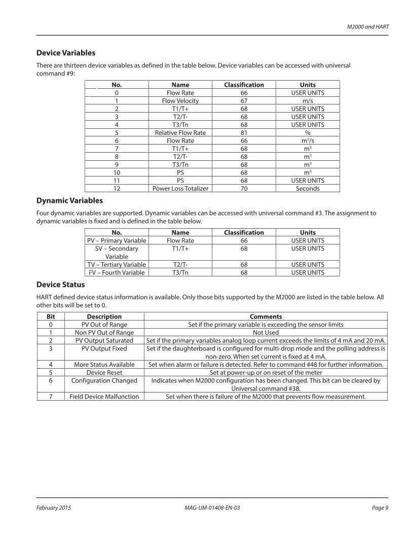
Device VariablesThere are thirteen device variables as defined in the table below . Device variables can be accessed with universal command #9:
No. Name Classification Units0 Flow Rate 66 USER UNITS1 Flow Velocity 67 m/s2 T1/T+ 68 USER UNITS3 T2/T- 68 USER UNITS4 T3/Tn 68 USER UNITS5 Relative Flow Rate 81 %6 Flow Rate 66 m3/s7 T1/T+ 68 m3
8 T2/T- 68 m3
9 T3/Tn 68 m3
10 PS 68 m3
11 PS 68 USER UNITS12 Power Loss Totalizer 70 Seconds
Dynamic VariablesFour dynamic variables are supported . Dynamic variables can be accessed with universal command #3 . The assignment to dynamic variables is fixed and is defined in the table below .
No. Name Classification UnitsPV – Primary Variable Flow Rate 66 USER UNITS
SV – Secondary Variable
T1/T+ 68 USER UNITS
TV – Tertiary Variable T2/T- 68 USER UNITSFV – Fourth Variable T3/Tn 68 USER UNITS
Device StatusHART defined device status information is available . Only those bits supported by the M2000 are listed in the table below . All other bits will be set to 0 .
Bit Description Comments0 PV Out of Range Set if the primary variable is exceeding the sensor limits1 Non PV Out of Range Not Used2 PV Output Saturated Set if the primary variables analog loop current exceeds the limits of 4 mA and 20 mA .3 PV Output Fixed Set if the daughterboard is configured for multi-drop mode and the polling address is
non-zero . When set current is fixed at 4 mA .4 More Status Available Set when alarm or failure is detected . Refer to command #48 for further information .5 Device Reset Set at power-up or on reset of the meter6 Configuration Changed Indicates when M2000 configuration has been changed . This bit can be cleared by
Universal command #38 .7 Field Device Malfunction Set when there is failure of the M2000 that prevents flow measurement .
M2000 and HART
Page 9 February 2015 MAG-UM-01408-EN-03
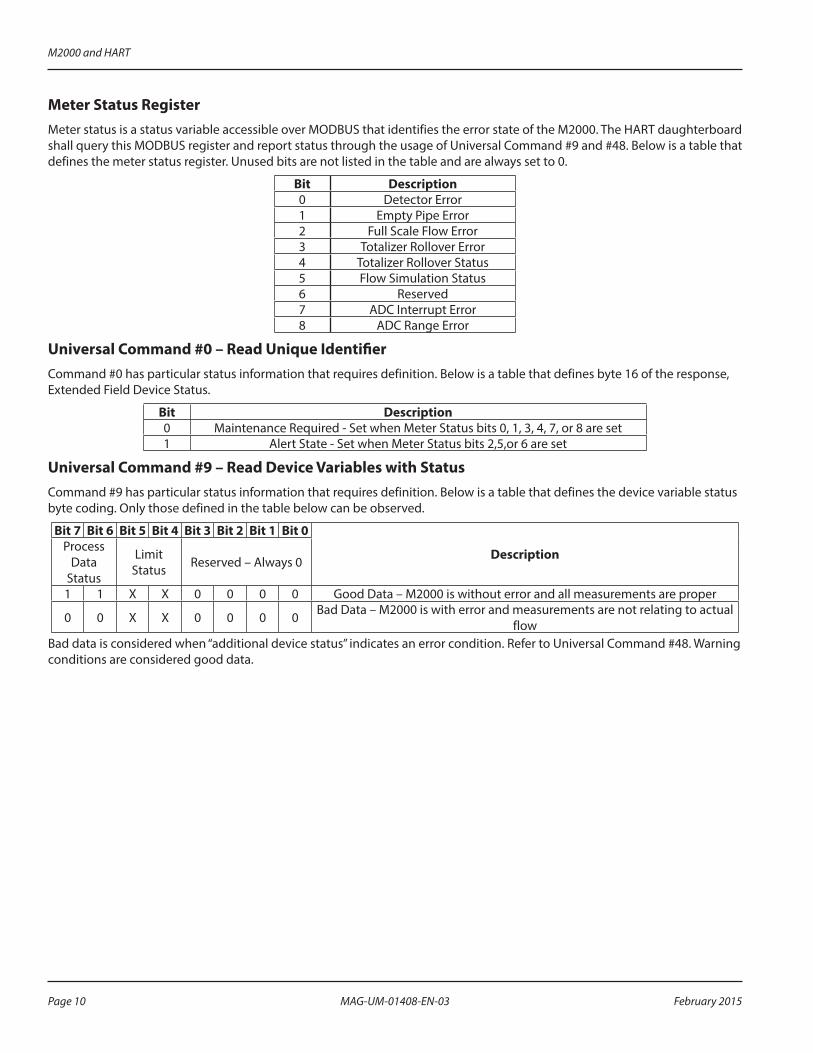
Meter Status RegisterMeter status is a status variable accessible over MODBUS that identifies the error state of the M2000 . The HART daughterboard shall query this MODBUS register and report status through the usage of Universal Command #9 and #48 . Below is a table that defines the meter status register . Unused bits are not listed in the table and are always set to 0 .
Bit Description0 Detector Error1 Empty Pipe Error2 Full Scale Flow Error3 Totalizer Rollover Error4 Totalizer Rollover Status5 Flow Simulation Status6 Reserved7 ADC Interrupt Error8 ADC Range Error
Universal Command #0 – Read Unique IdentifierCommand #0 has particular status information that requires definition . Below is a table that defines byte 16 of the response, Extended Field Device Status .
Bit Description0 Maintenance Required - Set when Meter Status bits 0, 1, 3, 4, 7, or 8 are set1 Alert State - Set when Meter Status bits 2,5,or 6 are set
Universal Command #9 – Read Device Variables with StatusCommand #9 has particular status information that requires definition . Below is a table that defines the device variable status byte coding . Only those defined in the table below can be observed .
Bit 7 Bit 6 Bit 5 Bit 4 Bit 3 Bit 2 Bit 1 Bit 0
DescriptionProcess Data
Status
Limit Status Reserved – Always 0
1 1 X X 0 0 0 0 Good Data – M2000 is without error and all measurements are proper
0 0 X X 0 0 0 0 Bad Data – M2000 is with error and measurements are not relating to actual flow
Bad data is considered when “additional device status” indicates an error condition . Refer to Universal Command #48 . Warning conditions are considered good data .
M2000 and HART
Page 10 February 2015MAG-UM-01408-EN-03

Universal Command #48 – Read Additional Device StatusCommand #48 returns 8 bytes of data that is specific to the M2000 HART daughterboard . The following table defines the status information for the reply to this command . Unused bits are not listed in the table and are always set to 0 . Some of these bits influence the device status bits shown in the Device Status Bits Set column:
Byte Bit Description Class Device Status Bits Set
0
0 Detector Error Error 4, 71 Empty Pipe Error Error 4, 72 Full Scale Flow Error Warning 0, 43 Totalizer Rollover Error Error 4, 7 4 Totalizer Rollover Status Warning 45 Flow Simulation Status Warning 4
6 Pulse Synchronization Warning Warning 4
7 ADC Interrupt Error Error 4, 71 0 ADC Range Error Error 4, 7
4 0 Internal Communication Failure Error 4, 7
1 Configuration Error Warning 4The “internal communication failure” status bit, byte 4 bit 0, is set when MODBUS communication between the meter and the daughterboard have failed . Verify that the diagnostic, bi-color LED on the daughterboard is blinking both status indicators (red and green) . If both colors are not observed, then power cycle the meter .The “Configuration Error” status bit, byte 4 bit 1, is set when a mismatch between the meter’s configuration and that reported over the HART protocol . Generally, this implies the intended value for the parameter was invalid . Below are some examples for how this bit could be set .
Example #1: Intended value is invalid
If the configured function for output #1 is set to 24V DC supply, the output type has to be normally open . If the intended value for the output type is normally closed, the configuration error flag will be set indicating the intended value was invalid due to its dependency on the function of the output .
Example #2: Writing to a secured meter
If connected to a secured meter, and you try to change a parameter after the login timer has expired, the “Configuration Error” indicates that the parameter image between HART and the M2000 is not equal .
M2000 and HART
Page 11 February 2015 MAG-UM-01408-EN-03

ADDITIONAL FEATURES
SecurityThe M2000 Security feature, when enabled, also applies to remote access (that is, HART) . Refer to the M2000 IOM for information on how to configure security . Remote reads are always allowed regardless of security rights . Remote writes using the HART protocol are not allowed unless the user has remotely logged into the meter with the appropriate access level . The remote login pins are the same as the login pins that are used on the M2000 display . Remote writes are not allowed if a user is actively navigating the menus at the display . Remote login expires five minutes after the last remote write . To remotely logout more quickly, do one of the following:
• Write an invalid pin to the Remote Login parameter .
• Send a remote logoff action request to the Service parameter .
Access levels for writable parameters are defined in the Data Management section .The security status of the meter is accessible using device specific command #243 . The response data is defined in the following table:
Bit Definition0 If set indicates meter is secured1 If set indicates menu access level is NONE2 If set indicates menu access level is USER3 If set indicates menu access level is SERVICE4 If set indicates menu access level is ADMIN5 If set indicates menu access level is FACTORY6 Not Defined7 Not Defined8 If set indicates remote access level is NONE9 If set indicates remote access level is USER
10 If set indicates remote access level is SERVICE11 If set indicates remote access level is ADMIN12 If set indicates remote access level is FACTORY13 Not Defined14 Not Defined15 Not Defined
Additional Features
Page 12 February 2015MAG-UM-01408-EN-03

Fixed Current Mode (Multi-Drop)The M2000 provides an active analog output . This means it is the source of the analog signal . When placing the meter into fixed current mode, the M2000 shall fix the output current to 4 mA regardless of the primary variables value (that is, Flow Rate) . During this condition the device status bit 3 (PV Analog Channel Fixed) is set . To place the meter into fixed current mode, the polling address must be non-zero . This is a HART specific parameter . The polling address is not accessible within the M2000 menu structure . Changing this value when the meter is secured is not prevented . With reference to the HART DD, this parameter is located at Configuration > Hart > Hart Output > Poll Addr . Each meter to be commissioned for multi-drop should exercise the following procedure . The default polling address for all HART daughterboards is 0 .1 . Turn off power to all meters to be commissioned for HART multi-drop mode .
MPORTANTIAs a result of the M2000 having an active analog output, only five M2000s can be configured for multi-drop mode within the same network.
2 . Wire the meters in parallel as shown in Figure 5:
4241
41 42
4241
250 ΩLoad
Polling Address = 1
Polling Address = 2
Polling Address = 3
4443
4443
4443
Amp Meter 12 mA
Figure 5: Wiring Meters in Parallel
3 . Turn on power to one of the meters . 4 . Change the polling address to desired address . As a suggestion, it may be desirable to change the installation data
while changing the polling address . Installation data can provide additional means for identifying the meter on the HART network .
5 . Repeat this procedure until all nodes on the HART multi-drop network are configured with a non-zero and unique polling address .
MPORTANTIThe analog output alarm mode has no effect while the meter is configured for multi-drop mode.
Additional Features
Page 13 February 2015 MAG-UM-01408-EN-03

Command Action RequestThere are several remote actions that can be requested of the meter over HART . Below is a table that defines the remote actions that can be taken including the level of security required if the meter is secured . To issue an action to the meter, access the command action parameter at Configuration > M2000 > Advanced > Miscellaneous > Service .
Value Security Description6 NONE Save Totalizers to EEPROM7 SERVICE Clear T1 or T+8 SERVICE Clear T2 or T-9 SERVICE Clear T3 or Tn
10 SERVICE Clear All Totalizers11 SERVICE Clear Port A Diagnostics12 SERVICE Clear Port B Diagnostics13 SERVICE Clear All Error Counts21 SERVICE Clear Power Off Totalizer23 SERVICE Remote Reset (power cycle)27 SERVICE Reset Batch Amount28 NONE Logoff Remote— — No Action
Empty Pipe CalibrationEmpty Pipe Calibration is an application embedded within the DD file that allows for remote calibration of empty pipe . Navigate to Configuration > M2000 > Advanced > Empty Pipe and select Empty Pipe Calib to start the application . Follow the on-screen instructions for further details .
• It may take up to 30 seconds for each pipe condition’s reading to stabilize . During this time, the following message displays, “Wait while reading stabilizes .“
• Executing the empty pipe calibration application will leave Empty Pipe enabled regardless of the state prior to execution .
Additional Features
Page 14 February 2015MAG-UM-01408-EN-03

Analog Output CalibrationAnalog Output Calibration is an application embedded within the DD file that allows for remote configuration of the analog output . Navigate to Configuration > M2000 > Advanced > Analog Output and select D/A Trim . Follow the on-screen instructions for further details .Do not exercise the D/A Trim application if meter is configured in multi-drop mode . The output current is fixed in multi-drop mode (that is, Polling address is non-zero) .This application uses the custom offsets . The deviation from 4 mA and 20 mA must be entered in terms of milliamperes . Recalibration will take effect once all offsets are configured and the application has completed .Figure 6 is an example of a diagram for a setup intended to assist in calibrating the analog output .
4241
250 ΩLoad
Polling Address = 04443
Reference MeterFluke Amp Meter
Handheld Field Communicator
Figure 6: Setup to Assist in Calibrating Analog Output
Additional Features
Page 15 February 2015 MAG-UM-01408-EN-03

DATA MANAGEMENTBelow is a table identifying all M2000 specific data that is accessible over HART . This table lists the HART Protocol commands used to access the data . This table also lists the security privileges and data types of the data . Typically the DD files handle all data access . Refer to the DD files for further information .
Product Identification
No.: Write Security Register Name Register TypeHART Command Support
(DS = Device Specific UN = Universal)
1 FIRMWARE Product Code UINT16 DS 130 (Read)2 FIRMWARE Product Name UCHAR16[8] DS 131 (Read)3 FIRMWARE Firmware Name UCHAR16[16] DS 132 (Read)4 FACTORY Application Version UCHAR16[10] DS 133 (Read)5 FIRMWARE Compile Date [MM:DD:YYYY] UCHAR16[16] DS 134 (Read)6 FIRMWARE Compile Time [HH:MM:SS] UCHAR16[16] DS 134 (Read)7 FACTORY PCB Serial Number UCHAR16[5] DS 141 (Read)8 FIRMWARE OTP Boot Checksum UCHAR16[3] DS 135 (Read)9 FIRMWARE Flash OS Checksum UCHAR16[3] DS 136 (Read)
10 FIRMWARE Boot Version UCHAR16[5] DS 137 (Read)11 FIRMWARE Os Version UCHAR16[4] DS 138 (Read)12 NONE Daughterboard Product Type UINT16 DS 139 (Read)13 NONE Daughterboard Major Version UINT16 DS 140 (Read)14 NONE Daughterboard Minor Version UINT16 DS 140 (Read)15 NONE Meter Tag Name UCHAR16[17] UN 20/22 (Read/Write)
Meter Calibration
No.: Write Security Register Name Register TypeHART Command Support
(DS = Device Specific UN = Universal)
16 ADMIN Detector Diameter UINT16 DS 150 (Read)17 ADMIN Detector Diameter Other [mm] UINT16 DS 152 (Read)18 ADMIN Detector Factor FLOAT32 DS 154 (Read)19 ADMIN Detector Offset [m/s] FLOAT32 DS 156 (Read)20 ADMIN Amplifier Factor FLOAT32 DS 158 (Read)21 ADMIN Detector Current [mA] FLOAT32 DS 160 (Read)22 SERVICE Power Line Frequency [Hz] UINT16 DS 162/163 (Read/Write)23 ADMIN Excitation Frequency [Hz] UINT16 DS 164/165 (Read/Write)24 SERVICE Scale Factor [%] FLOAT32 DS 166/167 (Read/Write)
Data Management
Page 16 February 2015MAG-UM-01408-EN-03

Meter Measurement Settings
No.: Write Security Register Name Register TypeHART Command Support
(DS = Device Specific UN = Universal)
25 USER Flow Unit UINT16 DS 175/176 (Read/Write)26 USER Volume Unit UINT16 DS 177/178 (Read/Write)27 USER Unit Multiplier UINT16 DS 179/180 (Read/Write)28 USER Full Scale Velocity [m/s] FLOAT32 DS 181/182 (Read/Write)29 USER Full Scale Flow [User Units] FLOAT32 DS 173/174 (Read/Write)30 USER Low Flow Cutoff [%] FLOAT32 DS 183/184 (Read/Write)31 USER Flow Direction UINT16 DS 185/186 (Read/Write)32 USER Damping Factor [s] UINT16 DS 187/188 (Read/Write)
Digital Input
No.: Write Security Register Name Register TypeHART Command Support
(DS = Device Specific UN = Universal)
33 SERVICE Digital Input: Input Operation UINT16 DS 190/191 (Read/Write)34 FIRMWARE Digital Input: Status UINT16 DS 192 (Read)
Analog Output
No.: Write Security Register Name Register TypeHART Command Support
(DS = Device Specific UN = Universal)
35 SERVICE Analog Customer Offset 4 MA [A] FLOAT32 DS 193/194 (Read/Write)36 SERVICE Analog Customer Offset 20 MA [A] FLOAT32 DS 195/196 (Read/Write)37 FIRMWARE Analog Output Current [ A ] FLOAT32 UN 2/3 - (Read /Read)38 SERVICE Alarm Mode UINT16 DS 197 (Write)39 NONE Fixed Current Mode FLOAT32 UN 6/7 (Read/Write)
Output #1
No.: Write Security Register Name Register TypeHART Command Support
(DS = Device Specific UN = Universal)
40 SERVICE Output #1: Pulses Per Unit [User Units] FLOAT32 DS 200/201) Read/Write)41 SERVICE Output #1: Pulse Width [ms] UINT16 DS 202/203 (Read/Write)42 SERVICE Output #1: Flow Alarm Minimum [%] UINT16 DS 204/205 (Read/Write)43 SERVICE Output #1: Flow Alarm Maximum [%] UINT16 DS 206/207 (Read/Write)44 SERVICE Output #1: Output Mode UINT16 DS 208/209 (Read/Write)45 SERVICE Output #1: Output Operation UINT16 DS 210/211 (Read/Write)
Output #2
No.: Write Security Register Name Register TypeHART Command Support
(DS = Device Specific UN = Universal)
46 SERVICE Output #2: Pulses Per Unit [User Units] FLOAT32 DS 200/201 (Read/Write)47 SERVICE Output #2: Pulse Width [ms] UINT16 DS 202/203 (Read/Write)48 SERVICE Output #2: Flow Alarm Minimum [%] UINT16 DS 204/205 (Read/Write)49 SERVICE Output #2: Flow Alarm Maximum [%] UINT16 DS 206/207 (Read/Write)50 SERVICE Output #2: Output Mode UINT16 DS 208/209 (Read/Write)51 SERVICE Output #2: Output Operation UINT16 DS 210/211 (Read/Write)
Data Management
Page 17 February 2015 MAG-UM-01408-EN-03

Output #3
No.: Write Security Register Name Register TypeHART Command Support
(DS = Device Specific UN = Universal)
52 SERVICE Output #3:Full Scale Frequency [Hz] UINT16 DS 212/213 (Read/Write)53 SERVICE Output #3: Flow Alarm Minimum [%] UINT16 DS 204/205 (Read/Write)54 SERVICE Output #3: Flow Alarm Maximum [%] UINT16 DS 206/207 (Read/Write)55 SERVICE Output #3: Output Mode UINT16 DS 208/209 (Read/Write)56 SERVICE Output #3: Hardware Select UINT16 DS 214/215 (Read/Write)57 SERVICE Output #3: Output Operation UINT16 DS 210/211 (Read/Write)
Output #4
No.: Write Security Register Name Register TypeHART Command Support
(DS = Device Specific UN = Universal)
58 SERVICE Output #4: Flow Alarm Minimum [%] UINT16 DS 204/205 (Read/Write)59 SERVICE Output #4: Flow Alarm Maximum [%] UINT16 DS 206/207 (Read/Write)60 SERVICE Output #4: Output Mode UINT16 DS 208/209 Read/Write)61 SERVICE Output #4: Hardware Select UINT16 DS 214/215 Read/Write)62 SERVICE Output #4: Output Operation UINT16 DS 210/211 Read/Write)
Port A Diagnostic Counters
No.: Write Security Register Name Register TypeHART Command Support
(DS = Device Specific UN = Universal)
63 FIRMWARE Port A: Packets Processed UINT16 DS 220 (Read)64 FIRMWARE Port A: Broadcast Packets UINT16 DS 220 (Read)65 FIRMWARE Port A: CRC Errors UINT16 DS 220 (Read)66 FIRMWARE Port A: Packets Received UINT16 DS 220 (Read)67 FIRMWARE Port A: Packets Sent UINT16 DS 220 (Read)68 FIRMWARE Port A: Parity Errors UINT16 DS 220 (Read)69 FIRMWARE Port A: Framing Errors UINT16 DS 220 (Read)70 FIRMWARE Port A: Overrun Errors UINT16 DS 220 (Read)71 FIRMWARE Port A: Break Detects UINT16 DS 220 (Read)
Port B Diagnostic Counters
No.: Write Security Register Name Register TypeHART Command Support
(DS = Device Specific UN = Universal)
72 FIRMWARE Port B: Packets Processed UINT16 DS 221 (Read)73 FIRMWARE Port B: Broadcast Packets UINT16 DS 221 (Read)74 FIRMWARE Port B: CRC Errors UINT16 DS 221 (Read)75 FIRMWARE Port B: Packets Received UINT16 DS 221 (Read)76 FIRMWARE Port B: Packets Sent UINT16 DS 221 (Read)77 FIRMWARE Port B: Parity Errors UINT16 DS 221 (Read)78 FIRMWARE Port B: Framing Errors UINT16 DS 221 (Read)79 FIRMWARE Port B: Overrun Errors UINT16 DS 221 (Read)80 FIRMWARE Port B: Break Detects UINT16 DS 221 (Read)
Data Management
Page 18 February 2015MAG-UM-01408-EN-03

Measurements
No.: Write Security Register Name Register TypeHART Command Support
(DS = Device Specific UN = Universal)
81 FIRMWARE T1 / T+ [m3] FLOAT32 UN 9 (Read)82 FIRMWARE T1 / T+ [User Units] FLOAT32 UN 3/9 (Read)83 FIRMWARE T2 / T- [m3] FLOAT32 UN 9 (Read)84 FIRMWARE T2 / T- [User Units] FLOAT32 UN 3/9 (Read)85 FIRMWARE T3 / TN [m3] FLOAT32 UN 9 (Read)86 FIRMWARE T3 / TN [User Units] FLOAT32 UN 3/9 (Read)87 FIRMWARE T1 / T+ Rollover Counter UINT16 DS 239 (Read)88 FIRMWARE T2 / T- Rollover Counter UINT16 DS 239 (Read)89 FIRMWARE Flow Velocity [m/s] FLOAT32 UN 9 (Read)90 FIRMWARE Flow Rate [m3/s] FLOAT32 UN 9 (Read)91 FIRMWARE Flow Rate [User Units] FLOAT32 UN 1/3/9 (Read)92 FIRMWARE Relative Flow Rate [ % ] FLOAT32 UN 2/9 (Read)93 FIRMWARE Preset Batch Totalizer [m3] FLOAT32 UN 9 (Read)94 FIRMWARE Preset Batch Totalizer [User Units] FLOAT32 UN 9 (Read)95 FIRMWARE Flow Direction UINT16 DS 239 (Read)
Meter Diagnostic Counters
No.: Write Security Register Name Register TypeHART Command Support
(DS = Device Specific UN = Universal)
96 FIRMWARE Power Up Counter UINT16 DS 222 (Read)97 FIRMWARE Detector Error Counter UINT16 DS 222 (Read)98 FIRMWARE Empty Pipe Counter UINT16 DS 222 (Read)99 FIRMWARE Full Scale Counter UINT16 DS 222 (Read)
100 FIRMWARE Totalizer Overflow Counter UINT16 DS 222 (Read)101 FIRMWARE Pulse Sync Counter UINT16 DS 222 (Read)102 FIRMWARE ADC Interrupt Counter UINT16 DS 222 (Read)103 FIRMWARE ADC Range Counter UINT16 DS 222 (Read)104 FIRMWARE WDT Resets Counter UINT16 DS 222 (Read)105 FIRMWARE WDT Location UINT16 DS 222 (Read)106 FIRMWARE System Error # UINT16 DS 222 (Read)107 FIRMWARE Meter Status UINT16 UN 48 (Read)108 FIRMWARE Action Request Overflows UINT16 DS 222 (Read)109 FIRMWARE Measurement Overflows UINT16 DS 222 (Read)110 FIRMWARE Remote Resets UINT16 DS 222 (Read)
Miscellaneous
No.: Write Security Register Name Register TypeHART Command Support
(DS = Device Specific UN = Universal)
111 FIRMWARE Power Loss Totalizer [ seconds ] UINT32 UN 9 (Read)112 USER Display Backlight Mode UINT16 DS 225/226 (Read/Write)113 SERVICE Preset Batch Amount [m3] FLOAT32 DS 227/228 (Read/Write)114 USER Menu Language Setting UINT16 DS 229/230 (Read/Write)115 NONE Port B Extended Address UINT16 UN 6/7 (Read/Write)
Data Management
Page 19 February 2015 MAG-UM-01408-EN-03
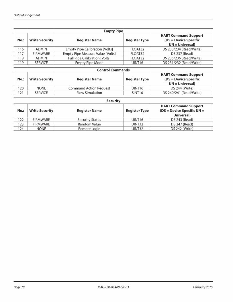
Empty Pipe
No.: Write Security Register Name Register TypeHART Command Support
(DS = Device Specific UN = Universal)
116 ADMIN Empty Pipe Calibration [Volts] FLOAT32 DS 233/234 (Read/Write)117 FIRMWARE Empty Pipe Measure Value [Volts] FLOAT32 DS 237 (Read)118 ADMIN Full Pipe Calibration [Volts] FLOAT32 DS 235/236 (Read/Write)119 SERVICE Empty Pipe Mode UINT16 DS 231/232 (Read/Write)
Control Commands
No.: Write Security Register Name Register TypeHART Command Support
(DS = Device Specific UN = Universal)
120 NONE Command Action Request UINT16 DS 244 (Write)121 SERVICE Flow Simulation SINT16 DS 240/241 (Read/Write)
Security
No.: Write Security Register Name Register TypeHART Command Support
(DS = Device Specific UN = Universal)
122 FIRMWARE Security Status UINT16 DS 243 (Read)123 FIRMWARE Random Value UINT32 DS 247 (Read)124 NONE Remote Login UINT32 DS 242 (Write)
Data Management
Page 20 February 2015MAG-UM-01408-EN-03

DEVICE DESCRIPTIONThe device descriptions, located on www.hartcomm.org under Product Catalog > All Products > M2000, can be installed into host systems such as the Emerson 475 Field Communicator . Periodically, the device description monitors the attached device for non-zero status codes (universal command #48) . These codes inform the user of the status of the M2000 . If the status of the M2000 does not clear, these informational dialogs will continue to be presented . To reduce the amount of dialogs, correct the state of the meter or configure the host to ignore these non-zero status codes . In addition, performing changes to the meter’s configuration generates a “configuration changed” status dialog . This bit must be manually cleared to prevent future display of this dialog . This can be done within the DD file by navigating to M2000>Advanced>Miscellaneous>Service>Reset Config Change or separately issuing universal command #38 .
TROUBLESHOOTING
Symptom Solution
Using DD files, not able to change values with the handheld —
Unable to communicate with the meter over HART
Check the wiring . Verify load is above minimum required resistance of 230 Ohms . Verify installation requirements are met (firmware v1 .10 or later, PCB serial number 1911xxxx or later) . Verify the loop current is within range, especially if configured for multi-drop .
Unable to find the calibration methods for empty pipe or the analog output
These methods only are visible when the meter is unsecured or when properly logged into a secured meter . For secured meters, these methods require SERVICE level authorization .
The configuration error flag is set
To eliminate this condition and any concerns regarding this condition, it is advisable to reset the M2000 . This can be done by issuing the RESET command in the Advanced>Miscellaneous>Service menu . Shortly thereafter the M2000 resets and the daughterboard image updates to match the M2000 image . Then re-verify all configuration data is as desired .
My analog current is always 4 mAVerify the meter is not configured for multi-drop mode . A meter configured for multi-drop mode will have a non-zero polling address . Set the polling address to zero . Verify flow rate is non-zero . Flow rate is directly proportional to the analog current .
Device Description
Page 21 February 2015 MAG-UM-01408-EN-03
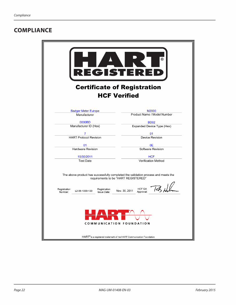
COMPLIANCE
Compliance
Page 22 February 2015MAG-UM-01408-EN-03

INTENTIONAL BLANK PAGE
Page 23 February 2015 MAG-UM-01408-EN-03
INTENTIONAL BLANK PAGE
User Manual

www.badgermeter.com
M-SERIES is registered trademark of Badger Meter, Inc . Other trademarks appearing in this document are the property of their respective entities . Due to continuous research, product improvements and enhancements, Badger Meter reserves the right to change product or system specifications without notice, except to the extent an outstanding contractual obligation exists . © 2015 Badger Meter, Inc . All rights reserved .
The Americas | Badger Meter | 4545 West Brown Deer Rd | PO Box 245036 | Milwaukee, WI 53224-9536 | 800-876-3837 | 414-355-0400México | Badger Meter de las Americas, S.A. de C.V. | Pedro Luis Ogazón N°32 | Esq. Angelina N°24 | Colonia Guadalupe Inn | CP 01050 | México, DF | México | +52-55-5662-0882Europe, Middle East and Africa | Badger Meter Europa GmbH | Nurtinger Str 76 | 72639 Neuffen | Germany | +49-7025-9208-0Europe, Middle East Branch Office | Badger Meter Europe | PO Box 341442 | Dubai Silicon Oasis, Head Quarter Building, Wing C, Office #C209 | Dubai / UAE | +971-4-371 2503 Czech Republic | Badger Meter Czech Republic s.r.o. | Maříkova 2082/26 | 621 00 Brno, Czech Republic | +420-5-41420411Slovakia | Badger Meter Slovakia s.r.o. | Racianska 109/B | 831 02 Bratislava, Slovakia | +421-2-44 63 83 01Asia Pacific | Badger Meter | 80 Marine Parade Rd | 21-06 Parkway Parade | Singapore 449269 | +65-63464836China | Badger Meter | 7-1202 | 99 Hangzhong Road | Minhang District | Shanghai | China 201101 | +86-21-5763 5412 Legacy Document: IOM-191-02-EN
Control. Manage. Optimize.
M-Series® M2000, HART® Bi-Directional Communication Protocol Data Access