m isc-m4 version ebruary - teknic
TRANSCRIPT
MERIDIAN ISC HARDWARE REFERENCE MANUAL MODELS ISC-M4XX/M5XX
VERSION 2.5/FEBRUARY 6, 2018
HARDWARE MANUAL
TEKNIC, INC FAX (585)784-7460 VOICE (585)784-7454

THIS PAGE INTENTIONALLY LEFT BLANK
TEKNIC, INC.
TABLE OF CONTENTS TABLE OF CONTENTS................................................. 1 INTRODUCTION........................................................... 2
Meridian ISC Overview..................................................................3 SAFETY....................................................................... 4
General Precautionary Statement .................................................4 Symbols Used in this Manual ........................................................4
MECHANICAL INSTALLATION...................................... 5 Mounting Information...................................................................5 Mounting and Clearance Dimensions ...........................................6 Notes on EMI and Grounding .......................................................7
ELECTRICAL INSTALLATION ....................................... 8 Overview: Electrical Isolation & Grounding .................................8
Grounding & Shielding Rules ............................................8 Meridian I/O Interface (J1) ...........................................................9
Wiring Examples: Meridian Output Devices .................. 10 Wiring Examples: Meridian Input Devices ......................11
Power Supply Requirements ....................................................... 13 Power Supply Current Requirements.............................. 13
Motor Connections to the Meridian ISC ..................................... 14 Overview .......................................................................... 14 Connecting Teknic motors to Meridian M4xx/M5xx Units
(connector P5) ....................................................................... 14 Connecting to Third Party Motors................................... 14 Guidelines for Motor Cable Construction ....................... 16
I/O Expansion Connector - P2 .................................................... 17 Communications Connectors – J2, J3 ........................................ 17
APPENDIX A: MERIDIAN ISC SPECIFICATIONS ........ 18 APPENDIX B: GOLDEN RULES OF INSTALLATION.... 22
Power............................................................................................22 Grounding and Shielding.............................................................22 Motor Cables ................................................................................22 Cable Making Guidelines.............................................................23
General Recommendations .............................................23 A Note on Hand Crimp Tools ..........................................24
APPENDIX C: CONNECTOR REFERENCE................. 25
TEKNIC, INC FAX (585)784-7460 VOICE (585)784-7454

INTRODUCTION Thank you for choosing the Meridian Integrated Servo Controller (ISC). The Meridian ISC incorporates a high-fidelity servo drive, integral motion controller and local I/O. This combination results in a high-performance machine control solution that integrates the motion trajectory generator with the servo controller in an easily extensible system architecture.
Each Meridian ISC features a dedicated, high-speed digital signal
processor (DSP) and onboard technology that supports the seamless integration of position, velocity, and torque loops. The unit’s DSP monitors the real-time state of the position/velocity compensator, motor magnetic field, amplifier output voltages, limit switch inputs, RMS motor current, and more. This high speed data stream provides the foundation upon which the Meridian ISC produces state-of-the art motion.
The Meridian ISC is the result of our 20+ year history of hardware,
software, and firmware development. That, combined with rapid advancements in DSP technology, allow Teknic to offer the systems designer benefits like:
The ISC’s high servo bandwidth ensures fast settling times, excellent tracking performance, ultra-smooth motion and tight velocity control for even the most demanding applications.
Our wide power class and form factor options maximize selection flexibility by allowing the machine designer to select the most appropriate model based on specific power requirements, size constraints, integration needs with other devices and budgetary goals.
Powerful and fully-integrated software prototyping tools enable the machine designer to quickly start electro-mechanical integration without the need for purpose-built software code, resulting in faster time-to-market.
The Meridian ISC has the flexibility to control permanent magnet
rotary and linear servomotors, voice coils, galvos, and most actuators on the market. Additionally, ISC units can be integrated together in an open control system architecture that leverages scalability and ease of development. The resulting solution provides excellent motion and I/O performance and outstanding overall value without the restrictions of proprietary systems.
2 VERSION 2.5/JUNE 9, 2021
TEKNIC, INC.
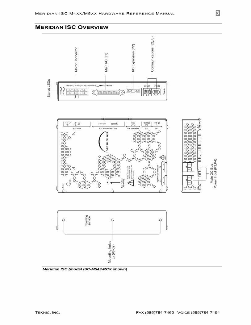
MERIDIAN ISC OVERVIEW
Com
mun
icat
ions
(J2,
J3)
Stat
us L
EDs
I/O E
xpan
sion
(P2)
Mai
n I/O
(J1)
Mot
or C
onne
ctor
Mou
ntin
g ho
les
3x (#
8-32
)
Mai
n D
C B
us
Pow
er In
put (
P3,P
4)
Inpu
t Pow
er 24
-90
VDC
P3P4
OutRED
InBLK
8-32
MERID
IAN
Pins 9-11
PE
[J2][J3]Expansion [P2]Motor [P5]
UP
For
vert
ical
mou
ntin
g Not
e: M
ount
uni
t ve
rtic
ally
for
max
ou
tput
pow
er if
not
fan
cool
ed.
I/O + Load Encoder [J1]
moun
ting
surfa
ce
RED BLK
Tekn
ic
Integrated Servo Drive + Controller MERIDIANTM
GR
N
RE
D
Meridian ISC (model ISC-M543-RCX shown)
MERIDIAN ISC M4XX/M5XX HARDWARE REFERENCE MANUAL 3
TEKNIC, INC. FAX (585)784-7460 VOICE (585)784-7454

SAFETY
GENERAL PRECAUTIONARY STATEMENT Always follow appropriate safety precautions when installing and commissioning ISC units and motors. Automated equipment should be designed to prevent personnel from coming into contact with moving parts and electrical contacts that could potentially cause injury or death. Read all cautions, warnings and notes before attempting to operate or service motion control devices. Follow all applicable codes and standards when using this equipment. Failure to use this equipment as described may impair or neutralize protections built into the product.
SYMBOLS USED IN THIS MANUAL The following symbols and conventions are used on the equipment and in this manual. Please read all equipment labels and manuals before attempting to use Meridian ISC units.
Caution, risk of danger
Identifies information about practices or circumstances that can lead to equipment damage, personal injury, or loss of life.
Shock hazard
Identifies presence of hazardous electrical voltages and currents.
Protective earth terminal
Indicates points that must be connected to a reliable earth system for safety compliance. Protective earth connections should never be omitted.
Earth ground terminal
Frame or chassis terminal (shield)
Direct current
Note
Identifies information that is critical for successful application and understanding of the product.
Tip
Identifies additional information that may be helpful in supporting certain applications.
4 VERSION 2.5/JUNE 9, 2021
TEKNIC, INC.

MECHANICAL INSTALLATION This section discusses mounting requirements for the Meridian ISC.
MOUNTING INFORMATION For the most effective heat dissipation, maximum continuous output power, and highest reliability, follow these mounting guidelines:
Mount all Meridian units as shown below. Drives should be screwed to a thermally conductive material such as steel or aluminum machine frame to provide maximum heat sinking.
Follow minimum clearance and spacing guidelines to ensure proper air flow through, around, and between Meridian units. Refer to mounting diagrams for important clearance and spacing requirements.
The Meridian ISC is rated for operation in ambient air temperatures of 0-40C (32-104F).
Note: For cabinet-mount installations: Mount Meridian ISC near the bottom of cabinet where air is
cooler. Use forced air cooling to improve performance and add
operating margin. At minimum, mount units in a vented enclosure that does not exceed maximum ambient air temperature.
Avoid mounting Meridian ISCs above heat sources such as power supplies, transformers, or spindle drives.
Input Power 24-90 VDCP3 P4
Out RED
In BLK
8-32
MERIDIAN
Pin
s 9-
11
PE
[J2]
[J3]
Expa
nsio
n [P
2]M
otor
[P5]
UP
For verticalmounting
Note: Mount unit vertically for max output power if notfan cooled.
I/O +
Loa
d En
code
r [J1
]
Unpainted, uncoatedmetal mounting surface
Mounting surfacebonded to machine
Protective Earth Terminal
PE
Mount withthis end up
Meridian mounting orientation
MERIDIAN ISC M4XX/M5XX HARDWARE REFERENCE MANUAL 5
TEKNIC, INC. FAX (585)784-7460 VOICE (585)784-7454

MOUNTING AND CLEARANCE DIMENSIONS
.079
.35
7.258
7.000
6.300
3.150
.6501.252
8-32 UNC-2B (3 typ) max useable thread depth .20 (5mm)
4.795
mountingsurface
1.01.0 1.0
Minimum SpacingRequirements
2.0 in.Between unitsBelow units
Above units1.0 in.1.5 in.
1.5
2.0 Enclosure
1.0
Input Power 24-90 VDCP3 P4
Out RED
In BLK
8-32
MERIDIAN
Pin
s 9-
11
PE
[J2]
[J3]
Expa
nsio
n [P
2]M
otor
[P5]
UP
For verticalmounting
Note: Mount unit vertically for max output power if notfan cooled.
I/O +
Loa
d En
code
r [J1
]
RED
BLK
Teknic
Inte
grat
ed S
ervo
Driv
e +
Con
trolle
rMERID
IAN
TM
GRN
RED
RED
BLK
Teknic
Inte
grat
ed S
ervo
Driv
e +
Con
trolle
rMERID
IAN
TM
GRN
RED
RED
BLK
Teknic
Inte
grat
ed S
ervo
Driv
e +
Con
trolle
rMERID
IAN
TM
GRN
RED
2.501.65
1.5.562
Mounting and clearance dimensions (M4xx/M5xx)
6 VERSION 2.5/JUNE 9, 2021
TEKNIC, INC.

NOTES ON EMI AND GROUNDING Electromagnetic Interference (EMI) can affect the quality and integrity of digital signals used in servo systems. One key to EMI suppression is to provide a low impedance RF return path between the motor case and the servo drive.
When using a third-party motor with your Meridian ISC unit, verify that the following conditions exist:
The motor phase shield is bonded to the motor case.
The motor phase shield is terminated at the motor cable connector. See Appendix C for Meridian connector and pin designations.
The motor extension cable (if used) carries the phase shield, uninterrupted, all the way back to the drive.
The motor phase shield does not contact or intermingle with the encoder/commutation signal shield at any point.
The communications power supply (24-42VDC) should be connected to the system only through the CON-MOD component as this component provides robust isolation and filtering.
No signal ground or I/O ground should be connected to chassis ground at any point.
Note: The Meridian’s protective earth connection is made through the mounting holes on the case extrusion. Connect these mounting holes to chassis ground ensuring direct metal to metal contact.
MERIDIAN ISC M4XX/M5XX HARDWARE REFERENCE MANUAL 7
TEKNIC, INC. FAX (585)784-7460 VOICE (585)784-7454

ELECTRICAL INSTALLATION Many time-saving and cost-saving details are presented in the schematic fragments and text that follow. Please read this entire section, as well as the “Golden Rules of Installation”, before integrating Meridian ISC units into your machine.
OVERVIEW: ELECTRICAL ISOLATION & GROUNDING In order to prevent ground loops in Meridian ISC systems, the control ground, power circuits, and chassis are electrically isolated from each other.
All logic-level signals are electrically isolated from the Meridian ISC's DC power input and motor output circuits, as well as from the chassis (case ground). This design feature ensures that control signals will not be compromised due to induced currents from the motor, power supply, or PWM return path. You can also daisy-chain the power wiring to multiple Meridian ISCs. This simplifies wiring requirements while simultaneously reducing cost and increasing system reliability.
Note: Always maintain separation between isolated control ground and power ground. See the “Golden Rules of Installation” for more details.
GROUNDING & SHIELDING RULES In order to meet EMC emissions specification EN-61000-6-4, and EMC immunity specification EN-61000-6-2, as well as EMC electrical safety specification EN-61010 (for CE/UL compliance) the following rules must be followed:
1. The ISC’s Protective Earth (PE) Ground must be connected to the machine’s safety ground.
2. The motor phase cable must be shielded. The shield must be connected to the motor case (on the motor end) and to the Chassis pin on the ISC motor connector (see Appendix C). The shield lead length at both ends of the cable should be as short as possible with a 2.0” maximum length.
3. The encoder and commutation sensor (Hall) cable must be separately shielded from the motor phase cable (even though the motor and encoder shields connect to the ISC chassis) in order to prevent motor PWM noise from traveling through the encoder shield. The motor and encoder shields must not touch at any point. The shield for the encoder cable must be left unconnected at the motor end (don’t connect it to the motor’s case).
Note: In scenarios where the motor is isolated from proper ground return paths (as when bench testing) temporary measures should be taken to comply with safety grounding requirements. Failure to do so can result in mechanical and/or electrical hazards.
8 VERSION 2.5/JUNE 9, 2021
TEKNIC, INC.

MERIDIAN I/O INTERFACE (J1) The Meridian ISC is compatible with many common I/O devices. This section contains example connection diagrams for common I/O devices including LEDs, incandescent lamps, solid state relays, coils, limit switches, mechanical switches, and open collector devices/sensors.
17 GPI-3 / - Limit
18 GND
6 +5V Out
5 GPI-2 / +Limit
19 GND
7 +5V Out
20 GND (Encoder)
14 Load Enc A (in)2 Load Enc A (in)
15 Load Enc B (in)3 Load Enc B (in)
16 Load Enc I (in)4 Load Enc I (in)
12 Vo+
25 GPO-0/ Brake
23 Vo-
5-24VDCExternal
13 Vo+
24 GPO-1
10 GPI 0
21 GPI 0 Return
11 GPI 1
22 GPI 1 Return
1 Chassis
9 +5V Out (Encoder)
8 +5V Out
Meridian internal schematicConnector J1
26C
32S
360
360
360
+5VDCInternal
Vo+
Vo+
47V
2k
2k
10mA
10mA
Vo-
47V
RED
BLK
Teknic
Inte
grat
ed S
ervo
Driv
e +
Con
trolle
rMERID
IAN
TM
GRN
RED
1 14
2513
Meridian main I/O connector - J1
MERIDIAN ISC M4XX/M5XX HARDWARE REFERENCE MANUAL 9
TEKNIC, INC. FAX (585)784-7460 VOICE (585)784-7454

WIRING EXAMPLES: MERIDIAN OUTPUT DEVICES
Meridian internal Connector J1
625mAmax.208mA
max.
13 Vo+
24 GPO-1
47V
23 Vo-
25 GPO-0/ Brake
12 Vo+
5-24VDCExternal
47V
Coils/Brakes
Meridian internal Connector J1
625mAmax.
208mAmax.
LED
Lamp
13 Vo+
24 GPO-1
47V
23 Vo-
25 GPO-0/ Brake
12 Vo+
5-24VDCExternal
47V
LED and incandescent indicator lamps
Meridian internal Connector J1
625mAmax.
SSR13 Vo+
24 GPO-1
47V
23 Vo-
25 GPO-0
12 Vo+
5-24VDCExternal
47V
AC
Load+
Solid state relay (SSR) with external AC load
10 VERSION 2.5/JUNE 9, 2021
TEKNIC, INC.

WIRING EXAMPLES: MERIDIAN INPUT DEVICES
Meridian internal Connector J1
10 GPI 0
21 GPI 0 Return
11 GPI 1
22 GPI 1 Return
10mA
10mA
17 GPI-3 / - Limit
18 GND
6 +5V Out
5 GPI-2 / +Limit
19 GND
7 +5V Out
+5VDCInternalSupply
2k
2k
+5VDC
+5VDC
Simple mechanical switches
17 GPI-3 / - Limit
18 GND
6 +5V Out
5 GPI-2 / +Limit
19 GND
7 +5V Out
Meridian internal
+5VDCInternalSupply
2k
2k
NPN, Dark-On SensorOMRON EE-SX671 Shown
Connector J1
Belden 9533
BLKWHT
REDLOUT
+
-
BLKWHT
REDLOUT
+
-
chassis
chassis
braid/shield
Limit switches
MERIDIAN ISC M4XX/M5XX HARDWARE REFERENCE MANUAL 11
TEKNIC, INC. FAX (585)784-7460 VOICE (585)784-7454

Meridian internal Connector J1
17 GPI-3 / - Limit
18 GND
6 +5V Out
5 GPI-2 / +Limit
19 GND
7 +5V Out
+5VDCInternalSupply
2k
2k
Open CollectorSensor (5VDC)
Open CollectorSensor (5VDC)
10 GPI 0
21 GPI 0 Return
11 GPI 1
22 GPI 1 Return
10mA
10mA
Open CollectorSensor (5-24VDC)
5-24VDC
Open CollectorSensor (5-24VDC)
5-24VDC
5 and 24VDC sensors
12 VERSION 2.5/JUNE 9, 2021
TEKNIC, INC.

POWER SUPPLY REQUIREMENTS The Meridian ISC requires an external DC power supply that can deliver high peak currents. Teknic recommends an unregulated “bulk” power supply—basically a transformer, rectifier, and large capacitor.
Switching power supplies are poorly suited to servo applications because:
Switchers usually have the same peak and continuous-current ratings, forcing you to purchase a large, but under-worked power supply just to meet peak current requirements.
Most switchers are not designed to accept the regenerated energy that a decelerating motor returns back to the power supply. This can cause a switching supply to power cycle, shutdown, or catastrophically fail in some instances.
The Meridian ISC takes DC input power at connectors P3 and P4.
These connectors are wired in parallel, so you can plug the power supply into either one. The power circuitry is electrically isolated from both isolated control ground (GND) and the chassis, allowing power to be daisy-chained from one unit to the next. This feature allows you to minimize the wiring harness while eliminating the potential for ground loops in the system.
Daisy-Chain Power Distribution
Input Power 24-90 VDCP3 P4
Out RED
In BLK
8-32
MERIDIAN
Pin
s 9-
11
PE
[J2]
[J3]
Expa
nsio
n [P
2]M
otor
[P5]
UP
For verticalmounting
Note: Mount unit vertically for max output power if notfan cooled.
I/O +
Loa
d En
code
r [J1
]
Input Power 24-90 VDCP3 P4
Out RED
In BLK
8-32
MERIDIAN
Pin
s 9-
11
PE
[J2]
[J3]
Expa
nsio
n [P
2]M
otor
[P5]
UP
For verticalmounting
Note: Mount unit vertically for max output power if notfan cooled.
I/O +
Loa
d En
code
r [J1
]
Input Power 24-90 VDCP3 P4
Out RED
In BLK
8-32
MERIDIAN
Pin
s 9-
11
PE
[J2]
[J3]
Expa
nsio
n [P
2]M
otor
[P5]
UP
For verticalmounting
Note: Mount unit vertically for max output power if notfan cooled.
I/O +
Loa
d En
code
r [J1
]
"Star" Power Distribution Input Power 24-90 VDC
P3 P4
Out RED
In BLK
8-32
MERIDIAN
Pin
s 9-
11
PE
[J2]
[J3]
Expa
nsio
n [P
2]M
otor
[P5]
UP
For verticalmounting
Note: Mount unit vertically for max output power if notfan cooled.
I/O +
Loa
d En
code
r [J1
]
Input Power 24-90 VDCP3 P4
Out RED
In BLK
8-32
MERIDIAN
Pin
s 9-
11
PE
[J2]
[J3]
Expa
nsio
n [P
2]M
otor
[P5]
UP
For verticalmounting
Note: Mount unit vertically for max output power if notfan cooled.
I/O +
Loa
d En
code
r [J1
]
Input Power 24-90 VDCP3 P4
Out RED
In BLK
8-32
MERIDIAN
Pin
s 9-
11
PE
[J2]
[J3]
Expa
nsio
n [P
2]M
otor
[P5]
UP
For verticalmounting
Note: Mount unit vertically for max output power if notfan cooled.
I/O +
Loa
d En
code
r [J1
]
Power Supply
Power Supply
“Daisy-chain” vs. “star” power distribution
POWER SUPPLY CURRENT REQUIREMENTS Current requirements are application dependent and therefore vary widely. See your Teknic support team for information on sizing a power supply for your Meridian system.
MERIDIAN ISC M4XX/M5XX HARDWARE REFERENCE MANUAL 13
TEKNIC, INC. FAX (585)784-7460 VOICE (585)784-7454

MOTOR CONNECTIONS TO THE MERIDIAN ISC
OVERVIEW Meridian ISCs can control not only Teknic servo motors, but also most third-party motors, including brush and brushless servo motors, linear motors, galvos, voice coils, and more. The following section describes how to connect the Meridian ISC to both Teknic, and third-party motors.
CONNECTING TEKNIC MOTORS TO MERIDIAN M4XX/M5XX UNITS (CONNECTOR P5) Teknic manufactures a line of quality rotary brushless DC servo motors ranging in size from NEMA 17 to NEMA 42 frame sizes. Connecting these motors to the M4xx and M5xx series ISC is simple, particularly if the drive and motor are mounted physically next to each other. In this case, you can just plug the motor directly into the drive.
1. Motor phase shield 2. Do not connect3. Comm. S-T 4. Comm. R-S5. Comm. T-R6. Encoder/Hall sensor shield7. Encoder/Hall GND8. EncoderA~
9. Motor phase R10. Motor phase S11. Motor phase T
12. +5V Out13. Encoder I
14. Encoder B15. Encoder A
16. Encoder B~
RED
BLK
Teknic
Inte
grat
ed S
ervo
Driv
e +
Con
trolle
rMERID
IAN
TM
GRN
RED
Motor Connector P5
Tip: Poorly manufactured cables are responsible for the majority of failures in OEM automated machines.
CONNECTING TO THIRD PARTY MOTORS The section below provides schematics, guidelines, and other details to follow when connecting a third party (non-Teknic) motor to a Meridian ISC. This section is also helpful if you plan on designing and/or building your own cables.
Mating connectors are specified in Appendix C (connector reference). Belden cable products are economical and have excellent electrical properties. They are a good choice for non-flex applications, but not appropriate for use in high-flex applications.
Olflex and others manufacture make high-flex cable products designed and lab tested to withstand millions of flex cycles. Your Teknic Application
14 VERSION 2.5/JUNE 9, 2021
TEKNIC, INC.

Engineer can recommend an appropriate cable stock for your project requirements.
10
11
15
8
14
16
13
3
4
5
7
12
6
9
1
MOTOR (P5)
MOTOR
ENCODER+
COMM.
ENC. A~
ENC. B~
COMM. S-T
COMM. R-S
COMM. T-R
GND
+5V-OUT
CHASSIS
Encoder/Hall Sensor Shield
Insulate shields at all points so they cannot short Connect motor phase
shield to motor case
Belden P/N 8770*RED
WHT
BLK
GRY/WHT
WHT/GRY
ORN/WHT
WHT/ORN
GRN/WHT
BLU/RED
RED/BLU
WHT/BLU
BRN/WHT
WHT/BRN
Belden P/N8106*DO NOT connect encoder cable shield to motor case
PE
Mating Connector: Molex/39-01-2160Contacts: Molex/39-00-0047 (24AWG)
Molex/39-00-039 (18AWG)
2 N/C
ENC. A
ENC. B
ENC. I
PHASE-R
PHASE-S
PHASE-T
* Cable stock shown is not for use inhigh-flex applications. Consult yourTeknic application engineer for recommended high flex cable stock.
Meridian motor cable connections (balanced encoder)
MERIDIAN ISC M4XX/M5XX HARDWARE REFERENCE MANUAL 15
TEKNIC, INC. FAX (585)784-7460 VOICE (585)784-7454
10
11
15
8
14
16
13
3
4
5
7
12
6
9
1
MOTOR (P5)
MOTOR
ENCODER+
COMM.
ENC. A
ENC. B
ENC. I
COMM. S-T
COMM. R-S
COMM. T-R
GND
+5V-OUT
PHASE-R
PHASE-S
PHASE-T
CHASSIS
Encoder/Hall Sensor Shield
Insulate shields at all points so they cannot short Connect motor phase
shield to motor case
Belden 8770*RED
WHT
BLK
GRY/WHT
ORN/WHT
GRN/WHT
BLU/RED
RED/BLU
WHT/BLU
BRN/WHT
WHT/BRN
Belden 8106*DO NOT connect encoder cable shield to motor case
PE
Mating Connector: Molex/39-01-2160Contacts: Molex/39-00-0047 (24AWG)
Molex/39-00-039 (18AWG)
2 N/C
* Cable stock shown is not for use inhigh-flex applications. Consult yourTeknic application engineer for recommended high flex cable stock.
N/C
N/C
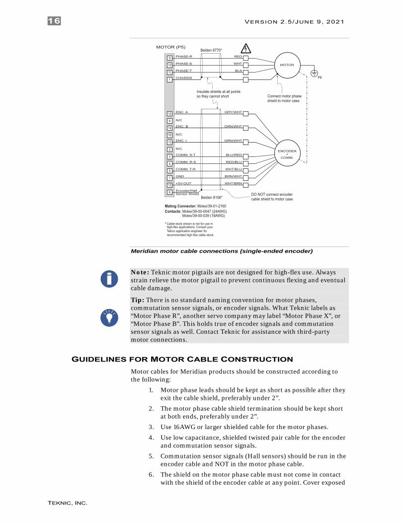
Meridian motor cable connections (single-ended encoder)
Note: Teknic motor pigtails are not designed for high-flex use. Always strain relieve the motor pigtail to prevent continuous flexing and eventual cable damage.
Tip: There is no standard naming convention for motor phases, commutation sensor signals, or encoder signals. What Teknic labels as “Motor Phase R”, another servo company may label “Motor Phase X”, or “Motor Phase B”. This holds true of encoder signals and commutation sensor signals as well. Contact Teknic for assistance with third-party motor connections.
GUIDELINES FOR MOTOR CABLE CONSTRUCTION Motor cables for Meridian products should be constructed according to the following:
1. Motor phase leads should be kept as short as possible after they exit the cable shield, preferably under 2”.
2. The motor phase cable shield termination should be kept short at both ends, preferably under 2”.
3. Use 16AWG or larger shielded cable for the motor phases.
4. Use low capacitance, shielded twisted pair cable for the encoder and commutation sensor signals.
5. Commutation sensor signals (Hall sensors) should be run in the encoder cable and NOT in the motor phase cable.
6. The shield on the motor phase cable must not come in contact with the shield of the encoder cable at any point. Cover exposed
16 VERSION 2.5/JUNE 9, 2021
TEKNIC, INC.

shield and drain wires with heat shrink tubing at termination points to prevent this. Failure to isolate these shields can result in loss of logic signal integrity and spurious failures and shutdowns.
7. Connect the motor phase cable shield to the motor case.
8. DO NOT connect the encoder cable shield to the motor case.
Warning! When connecting and disconnecting motors from Meridian ISCs:
1. Always disable the Meridian ISC before connecting or disconnecting a motor.
2. Verify that the proper motor configuration file is loaded in the Meridian unit before enabling it with a motor connected. This is particularly important if the configuration file currently loaded in the ISC is unknown, or if you have connected a different type of motor to the ISC.
3. Always reset the ISC after connecting or reconnecting a motor to it.
I/O EXPANSION CONNECTOR - P2
P2
RED
BLK
Teknic
Inte
grat
ed S
ervo
Driv
e +
Con
trolle
rMERID
IAN
TM
GRN
RED
Meridian Expansion Connector (P2)
COMMUNICATIONS CONNECTORS – J2, J3
J3
J2
RED
BLK
Teknic
Inte
grat
ed S
ervo
Driv
e +
Con
trolle
rMERID
IAN
TM
GRN
RED
Meridian Diagnostic and Application Communications Connectors
MERIDIAN ISC M4XX/M5XX HARDWARE REFERENCE MANUAL 17
TEKNIC, INC. FAX (585)784-7460 VOICE (585)784-7454

APPENDIX A: MERIDIAN ISC SPECIFICATIONS
ISC-M423-KCX Specifications GENERAL Dimensions, in. (mm): 7.31 (185) x 4.88 (124) x 1.16 (29)
Weight, oz. (g): 17 (494)
ENVIRONMENTAL Temperature: 0-40°C
Humidity: 0-90%, non-condensing
COMPLIANCE Electrical safety: EN 61010, UL508C
EMI: EN 61326
Machine safety: EN 954-1, with proper power control
OUTPUT POWER Peak Current: 20A
Continuous Current: 6A RMS
PWM ripple frequency: 28kHz, center balance vector type
Conversion Efficiency: >99%
COMPENSATOR TSPD: 35 µS
Position/Velocity control:
Enhanced PIV with proprietary velocity, acceleration and jerk estimators, Inertia Matching Technology (IMT), Regressive AutoSpline (RAS) and Anti-Hunt. Provides velocity, acceleration, jerk, and friction feed-forward gains
Torque control: Synchronous vector with DQ decoupling, SmartSaturation, and auto calibration
ENCODER Interface: Primary: Single-ended or differential, user selectable
Features: Bad sequence detection, digital filtering adjustable from 100kHz to 40MHz Secondary (load) encoder supported
MOTOR COMPATIBILITY Requirements: Rotary brush or 3-phase brushless rotary/linear motor
HALL SENSOR INPUTS Specifications: 5kΩ pull-up to +5V
Features: Digitally filtered; optical Hall sensors used for setting torque vector upon initialization only; drive can also operate in Hall-less mode
DEDICATED INTERFACE Interface: 5kΩ pull-up to +3.3VDC; digitally filtered
OUTPUTS GPO-0, GPO-1
Isolated, short-circuit protected, open collector outputs. 47V (active) clamping for directly driving inductive loads. Requires external 4-28VDC power supply GPO-0 625mA GPO-1 208mA
GPI-0, GPI-1 High-speed, optically isolated, Response time < 200nS, Operating voltage 4-28VDC requires 10mA, Can be used as capture inputs
INPUTS GPI-2, GPI-3
Can be user-configured as limit switch inputs, TTL with 2k pull-up, digitally filtered
PROTECTION & SAFETY FUNCTIONS Drive protection: Short circuit (phase-to-phase, phase-to-ground), over temp, over
voltage, over current, protected for open windings, fused.
Motor protection: True RMS torque limiting, automatic speed limit, motor jam detection, over temp
Mechanical safeguards: Hardstop detection, limit switch servoing, adjustable tracking error limits and shutdown thresholds, adjustable torque and speed limits
Electrical Isolation: 1.0mm (0.0394”)
+5VDC out of motor connector (encoder/hall power) 300mA max.
OTHER Dual encoder support Yes
INPUT SUPPLY Input voltage/current: Main DC (bus) power supply 24-90VDC
Input current (max) Input current (typical)
15A RMS Up to 6.75A RMS, application dependent
COUNTRY OF ORIGIN Manufactured in: USA
18 VERSION 2.5/JUNE 9, 2021
TEKNIC, INC.

ISC-M493-KCX Specifications GENERAL Dimensions, in (mm): 7.31 (185) x 4.88 (124) x 1.16 (29)
Weight, oz (g): 17 (494)
ENVIRONMENTAL Temperature: 0-40°C
Humidity: 0-90%, non-condensing
COMPLIANCE Electrical safety: EN 61010, UL508C
EMI: EN 61326
Machine safety: EN 954-1, with proper power control
OUTPUT POWER Peak Current: 23A
Continuous Current: 7A RMS
PWM ripple frequency: 28kHz, center balance vector type
Conversion Efficiency: >99%
COMPENSATOR TSPD: 35 µS
Position/Velocity control:
Enhanced PIV with proprietary velocity, acceleration and jerk estimators, Inertia Matching Technology (IMT), Regressive AutoSpline (RAS) and Anti-Hunt. Provides velocity, acceleration, jerk, and friction feed-forward gains
Torque control: Synchronous vector with DQ decoupling, SmartSaturation, and auto calibration
ENCODER Interface: Primary: Single-ended or differential, user selectable
Features: Bad sequence detection, digital filtering adjustable from 100kHz to 40MHz Secondary (load) encoder supported
MOTOR COMPATIBILITY Requirements: Rotary brush or 3-phase brushless rotary/linear motor
HALL SENSOR INPUTS Specifications: 5kΩ pull-up to +5V
Features: Digitally filtered; optical Hall sensors used for setting torque vector upon initialization only; drive can also operate in Hall-less mode
DEDICATED INTERFACE Interface: 5kΩ pull-up to +3.3VDC; digitally filtered
OUTPUTS GPO-0, GPO-1
Isolated, short-circuit protected, open collector outputs. 47V (active) clamping for directly driving inductive loads. Requires external 4-28VDC power supply GPO-0 625mA GPO-1 208mA
GPI-0, GPI-1 High-speed, optically isolated, Response time < 200nS, Operating voltage 4-28VDC requires 10mA, Can be used as capture inputs
INPUTS GPI-2, GPI-3
Can be user-configured as limit switch inputs, TTL with 2k pull-up, digitally filtered
PROTECTION & SAFETY FUNCTIONS Drive protection: Short circuit (phase-to-phase, phase-to-ground), over temp, over
voltage, over current, protected for open windings, fused.
Motor protection: True RMS torque limiting, automatic speed limit, motor jam detection, over temp
Mechanical safeguards: Hardstop detection, limit switch servoing, adjustable tracking error limits and shutdown thresholds, adjustable torque and speed limits
Electrical Isolation: 1.0mm (0.0394”)
+5VDC out of motor connector (encoder/hall power) 300mA max.
OTHER Dual encoder support Yes
INPUT SUPPLY Input voltage/current: Main DC (bus) power supply 24-90VDC
Input current (max) Input current (typical)
15A RMS Up to 6.75A RMS, application dependent
COUNTRY OF ORIGIN Manufactured in: USA
MERIDIAN ISC M4XX/M5XX HARDWARE REFERENCE MANUAL 19
TEKNIC, INC. FAX (585)784-7460 VOICE (585)784-7454

ISC-M523-RCX Specifications GENERAL Dimensions, in (mm): 7.31 (185) x 4.88 (124) x 1.16 (29)
Weight, oz (g): 17 (494)
ENVIRONMENTAL Temperature: 0-40°C
Humidity: 0-90%, non-condensing
COMPLIANCE Electrical safety: EN 61010, UL508C
EMI: EN 61326
Machine safety: EN 954-1, with proper power control
OUTPUT POWER Peak Current: 28A
Continuous Current: 8A RMS
PWM ripple frequency: 28kHz, center balance vector type
Conversion Efficiency: >99%
COMPENSATOR TSPD: 35 µS
Position/Velocity control:
Enhanced PIV with proprietary velocity, acceleration and jerk estimators, Inertia Matching Technology (IMT), Regressive AutoSpline (RAS) and Anti-Hunt. Provides velocity, acceleration, jerk, and friction feed-forward gains
Torque control: Synchronous vector with DQ decoupling, SmartSaturation, and auto calibration
ENCODER Interface: Primary: Single-ended or differential, user selectable
Features: Bad sequence detection, digital filtering adjustable from 100kHz to 40MHz Secondary (load) encoder supported
MOTOR COMPATIBILITY Requirements: Rotary brush or 3-phase brushless rotary/linear motor
HALL SENSOR INPUTS Specifications: 5kΩ pull-up to +5V
Features: Digitally filtered; used for setting torque vector upon initialization only; drive can also operate in Hall-less mode
DEDICATED INTERFACE Interface: 5kΩ pull-up to +3.3VDC; digitally filtered
OUTPUTS GPO-0, GPO-1
Isolated, short-circuit protected, open collector outputs. 47V (active) clamping for directly driving inductive loads. Requires external 4-28VDC power supply GPO-0 625mA GPO-1 208mA
GPI-0, GPI-1 High-speed, optically isolated, Response time < 200nS, Operating voltage 4-28VDC requires 10mA, Can be used as capture inputs
INPUTS GPI-2, GPI-3
Can be user-configured as limit switch inputs, TTL with 2k pull-up, digitally filtered
PROTECTION & SAFETY FUNCTIONS Drive protection: Short circuit (phase-to-phase, phase-to-ground), over temp, over
voltage, over current, protected for open windings, fused.
Motor protection: True RMS torque limiting, automatic speed limit, motor jam detection, over temp
Mechanical safeguards: Hardstop detection, limit switch servoing, adjustable tracking error limits and shutdown thresholds, adjustable torque and speed limits
Electrical Isolation: 1.0mm (0.0394”)
+5VDC out of motor connector (encoder/hall power) 300mA max.
OTHER Dual encoder support Yes
INPUT SUPPLY Input voltage/current: Main DC (bus) power supply 24-90VDC
Input current (max) Input current (typical)
15A RMS Up to 6.75A RMS, application dependent
COUNTRY OF ORIGIN Manufactured in: USA
20 VERSION 2.5/JUNE 9, 2021
TEKNIC, INC.
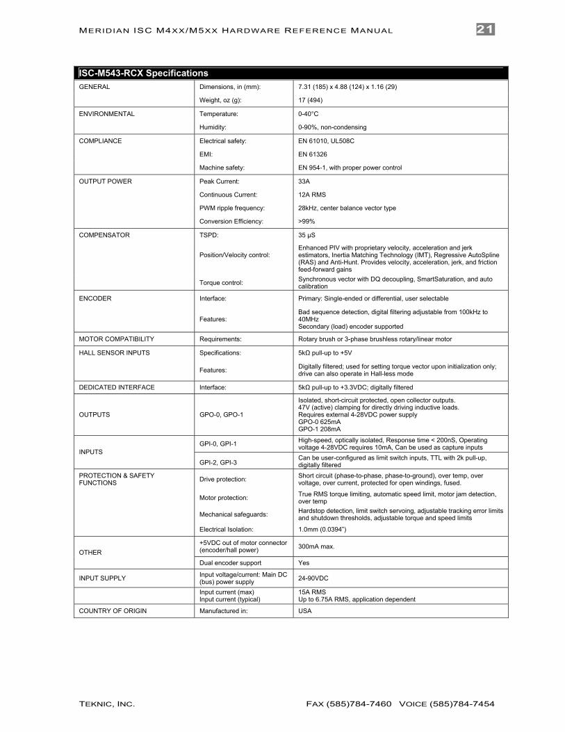
ISC-M543-RCX Specifications GENERAL Dimensions, in (mm): 7.31 (185) x 4.88 (124) x 1.16 (29)
Weight, oz (g): 17 (494)
ENVIRONMENTAL Temperature: 0-40°C
Humidity: 0-90%, non-condensing
COMPLIANCE Electrical safety: EN 61010, UL508C
EMI: EN 61326
Machine safety: EN 954-1, with proper power control
OUTPUT POWER Peak Current: 33A
Continuous Current: 12A RMS
PWM ripple frequency: 28kHz, center balance vector type
Conversion Efficiency: >99%
COMPENSATOR TSPD: 35 µS
Position/Velocity control:
Enhanced PIV with proprietary velocity, acceleration and jerk estimators, Inertia Matching Technology (IMT), Regressive AutoSpline (RAS) and Anti-Hunt. Provides velocity, acceleration, jerk, and friction feed-forward gains
Torque control: Synchronous vector with DQ decoupling, SmartSaturation, and auto calibration
ENCODER Interface: Primary: Single-ended or differential, user selectable
Features: Bad sequence detection, digital filtering adjustable from 100kHz to 40MHz Secondary (load) encoder supported
MOTOR COMPATIBILITY Requirements: Rotary brush or 3-phase brushless rotary/linear motor
HALL SENSOR INPUTS Specifications: 5kΩ pull-up to +5V
Features: Digitally filtered; used for setting torque vector upon initialization only; drive can also operate in Hall-less mode
DEDICATED INTERFACE Interface: 5kΩ pull-up to +3.3VDC; digitally filtered
OUTPUTS GPO-0, GPO-1
Isolated, short-circuit protected, open collector outputs. 47V (active) clamping for directly driving inductive loads. Requires external 4-28VDC power supply GPO-0 625mA GPO-1 208mA
GPI-0, GPI-1 High-speed, optically isolated, Response time < 200nS, Operating voltage 4-28VDC requires 10mA, Can be used as capture inputs
INPUTS GPI-2, GPI-3
Can be user-configured as limit switch inputs, TTL with 2k pull-up, digitally filtered
PROTECTION & SAFETY FUNCTIONS Drive protection: Short circuit (phase-to-phase, phase-to-ground), over temp, over
voltage, over current, protected for open windings, fused.
Motor protection: True RMS torque limiting, automatic speed limit, motor jam detection, over temp
Mechanical safeguards: Hardstop detection, limit switch servoing, adjustable tracking error limits and shutdown thresholds, adjustable torque and speed limits
Electrical Isolation: 1.0mm (0.0394”)
+5VDC out of motor connector (encoder/hall power) 300mA max.
OTHER Dual encoder support Yes
INPUT SUPPLY Input voltage/current: Main DC (bus) power supply 24-90VDC
Input current (max) Input current (typical)
15A RMS Up to 6.75A RMS, application dependent
COUNTRY OF ORIGIN Manufactured in: USA
MERIDIAN ISC M4XX/M5XX HARDWARE REFERENCE MANUAL 21
TEKNIC, INC. FAX (585)784-7460 VOICE (585)784-7454

APPENDIX B: GOLDEN RULES OF INSTALLATION
POWER 1. Ground the Meridian ISC to the machine chassis or frame. Use
unplated 10-32 screws to secure the case extrusion to the machine. Verify that the frame is connected to the machine’s Protective Earth Terminal (safety ground).
2. Don’t run the unit’s power return through the machine’s frame or chassis.
Note: The DC bus power—provided by the Amazon IPC power supply—is not referenced to ground. Both the positive and negative leads of the IPC carry hazardous voltages.
3. Daisy chaining power through the Meridian power connectors is safe and convenient. Full electrical isolation between the Meridian’s power and control signals means that “star” power distribution is not required.
4. Use heavy gauge wire for power cables.
GROUNDING AND SHIELDING 5. Use shielded cable for all control signal connections: the motor’s
encoder & commutation signals, optional connections and the I/O and limit cables. The encoder and controller cables should have low capacitance insulation. Low capacitance cable conductors are typically made from polyethylene, foamed polyethylene, Teflon®, FEP, etc.
6. Connect the control signal cable’s isolated control ground to the machine frame or chassis only at a single point at the controller. Do not hook isolated control ground to the machine frame or chassis at any other location.
7. Do not ground the limit switch circuit to the machine frame or chassis.
MOTOR CABLES 8. Use heavy gauge shielded cable for the motor phase wiring.
Connect the shield to pin 1 on the Meridian’s motor connector (case ground).
9. Don’t ground the encoder cable shield to the motor case or allow it to touch the motor phase shield at any point.
10. Don’t run the motor’s commutation (Hall) signals through the motor phase cable at any point.
11. Don’t run motor thermostat signals (if any) through the motor phase cable at any point.
22 VERSION 2.5/JUNE 9, 2021
TEKNIC, INC.
CABLE MAKING GUIDELINES The following guidelines sre included to help minimize cable design and fabrication problems.
GENERAL RECOMMENDATIONS 1. Avoid cables made with hand tools.
Hand crimping tools, when properly selected and used by a skilled operator, make good crimp connections. However, since these tools are expensive, typically $200 - $400 each, technicians rarely have the wide variety required to make proper crimps on all of the terminal types and wire sizes they encounter. Unfortunately, it’s easy to use the wrong tool and not realize it, or even more likely, to use the wrong tool and think it’s “probably OK”. These hand tools are awkward, cumbersome to use and often require the operator to master a certain “feel”. In addition, these hand tools don’t have any built-in quality assurance features.
In certain instances, you may be forced to make a hand crimped cable, for example, when you’re in a hurry for a custom length. If you do, be sure that you have the exact hand tool and die that the terminal manufacturer recommends (see below), perform a visual inspection to ensure that the insulation is captured in the terminal’s strain relief and do a pull test on each connection before inserting it into the connector. Be aware that machine-crimped cables will generally cost less than hand crimped versions and are likely to save thousands of dollars of debugging time.
2. Verify that your cable shop has all of the proper tools and equipment.
Use a cable shop that has automated presses for wire termination and make sure they have the proper applicator "heads" (dies) for the exact terminals used. (If they don't, consider buying applicator heads for them). It's strongly preferred that they have presses with automatic "crimp height" checking as this in-process check is the main measure of termination quality. Making this 100% check without requiring human intervention is a key advantage. If they don't have these automatic crimp-height-checking presses, make sure their general procedures include checking the crimp height on first articles and periodically during a run of cables. Under no circumstances should you accept a shop using hand tools.
3. Specify 100% electrical testing of all cables.
Specify that cables and harnesses be 100% electrically tested, preferably with resistance tests. The cable shop should have automated equipment by CableScan, DynaLab, CheckSum, or other vendors for this purpose. The fixture cost for 100% electrical testing is low, ranging from $0-$200 per cable assembly, and it's definitely worth it.
4. Be certain that all terminals are properly specified
Check all your terminal specifications carefully. Research all of your drawings and make certain that the terminals specified can accept the necessary wire gauges. Also, look carefully at the insulation diameter range supported by each terminal. If the insulation diameter range on the terminal is incorrect for the wire used, the individual wire strain relief will be compromised and this can lead to premature failure. Make certain that the plating between mating terminals is the same. Using gold is great, but not if you are mating with tin. Use gold plated sockets with gold plated
MERIDIAN ISC M4XX/M5XX HARDWARE REFERENCE MANUAL 23
TEKNIC, INC. FAX (585)784-7460 VOICE (585)784-7454
pins and tin plated sockets with tin plated pins to avoid galvanic corrosion.
5. Prepare complete pictorial drawings.
Create drawings that are pictorial in nature (i.e. visually representative of the subject). Include fabrication details such as jacket strip lengths, shield termination details, cable tie locations, marking details, etc. The more call-outs, detail views, and exploded views, the better. Visual communication is critical here. Don’t leave the details to the cable shop as "best practices" vary widely from shop to shop. Include the complete BOM right on the drawing. Finally, make the end-to-end cable length easy to modify. This may help reduce future drawing effort if you need similar cables of varying length at some point in the future.
A NOTE ON HAND CRIMP TOOLS When necessary, quality cables can be made with hand tools, provided that manufacturer’s guidelines are faithfully adhered to. An excellent web-based resource on this subject is the Molex document “Good Crimps and How to Recognize Them”, found in the Tech Library section of the Molex website. This collection of crimp-specific reference information includes how to identify good and bad crimps as well as best practices and specifications for crimp techniques and tooling.
Note: Though similar in appearance, each type of crimp terminal requires a specific handset and die set. Failure to use the proper tool, die set, or terminal for the job will result in poor quality terminations and premature cable harness failures.
Note: Cable failures due to poor crimp quality are the most common mode of failure for OEM machine manufacturers and their customers.
24 VERSION 2.5/JUNE 9, 2021
TEKNIC, INC.

APPENDIX C: CONNECTOR REFERENCE J1 – Main I/O Connector Pin Signal Name Mates With
1 Chassis 2 Load Encoder A (in)* 3 Load Encoder B (in)* 4 Load Encoder I (in)* 5 GPI-2/+Limit 6 +5V Out CONNECTOR
7 +5V Out AMP/207464-7 8 +5V Out
9 +5V Out (Encoder) CONTACTS 10 GPI-0 AMP/745254-2 (22-26 AWG) 11 GPI-1 12 Vo+ HOOD 13 Vo+ AMP/206478-3 14 Load Encoder A~ (in)* 15 Load Encoder B~ (in)* CRIMP TOOL 16 Load Encoder I~ (in)* AMP/58448-2
17 GPI-3/-Limit
WIRE ENTRY VIEW 18 GND PIN EXTRACTOR
19 GND AMP/91285-1
20 GND (Encoder) 21 GPI-0 Return 22 GPI-1 Return
23 Vo- 24 GPO-1 25 GPO-0/Brake
*Secondary encoder not supported on all models
P3, P4 Power Connector Pin Signal Name Mates With
1 V+ 2 V- CONNECTOR Molex/44441-2002 CONTACTS Molex/43375-1001 (14-18 AWG)
CRIMP TOOL
Molex/63811-7200 WIRE ENTRY VIEW
PIN EXTRACTOR Molex/63813-2700
MERIDIAN ISC M4XX/M5XX HARDWARE REFERENCE MANUAL 25
TEKNIC, INC. FAX (585)784-7460 VOICE (585)784-7454
1 2V+ V-
1
142513
Chassis 1.Load Encoder A (in) 2.Load Encoder B (in) 3.Load Encoder I (in) 4.
GPI-2/+Limit 5.+5V Out 6.+5V Out 7.+5V Out 8.
+5V Out (Encoder) 9.GPI-0 10.GPI-1 11.
Vo+ 12.Vo+ 13.
14. Load Encoder A~ (in)15. Load Encoder B~ (in)16. Load Encoder I~ (in)17. GPI-3/-Limit18. GND19. GND20. GND (Encoder)21. GPI-0 Return22. GPI-1 Return
24. GPO-123. Vo-
25. GPO-0/Brake

P5 Motor Connector Pin Signal Name Mates With
1 Motor Phase Shield 2 Do not connect CONNECTOR 3 Comm. S-T Molex/39-01-2160 4 Comm. R-S 5 Comm. T-R CONTACTS 6 Encoder/Hall Shields Molex/39-00-0047 (24 AWG)
7 Encoder/Hall GND Molex/39-00-0077 (16 AWG) 8 Encoder A~
9 Motor Phase R CRIMP TOOL WIRE ENTRY VIEW 10 Motor Phase S Molex/638190900
11 Motor Phase T (16-24 AWG) 12 +5V Out 13 Encoder I PIN EXTRACTOR 14 Encoder B Molex/11-03-0044 15 Encoder A 16 Encoder B~
26 VERSION 2.5/JUNE 9, 2021
TEKNIC, INC.
1. Motor phase shield 2. DO not connect3. Comm. S-T 4. Comm. R-S5. Comm. T-R6. Encoder/Hall sensor shield7. Encoder/Hall GND8. EncoderA~
9. Motor phase R10. Motor phase S11. Motor phase T
12. +5V Out13. Encoder I
14. Encoder B15. Encoder A
16. Encoder B~

Teknic Incorporated 115 Victor Heights Pkwy Victor, NY 14564
Copyright © 2018 Teknic Inc. All rights reserved
MERIDIAN ISC M4XX/M5XX HARDWARE REFERENCE MANUAL 27
TEKNIC, INC. FAX (585)784-7460 VOICE (585)784-7454