bridge design specifications • f ebruary 2004
TRANSCRIPT

BRIDGE DESIGN SPECIFICATIONS bull FEBRUARY 2004
(Fy3) in Equation (10-26) can be replaced by the allowable shearing stress given in Table 10321A
Transverse stiffeners shall be required if Dtw is greater than 150 The spacing of these stiffeners shall not exceed 2
Oslash 260 oslash the handling requirement DŒ œ
ordmD tw szlig
103443 The spacing of the first intermediate stiffener at the simple support end of a girder shall be such that the shearing stress in the end panel shall not exceed the value given by the following equation (the maximum spacing is limited to 15D)
C Fy FyFv = pound (10-29)3 3
103444 If a girder panel is subjected to simulshytaneous action of shear and bending moment with the
+ magnitude of the shear stress higher than 06Fv the + calculated bending stress shall not exceed the reduced + allowable bending stressFs determined by the following + equation
[ 034 f )F = 0754 - v Fs y (10-30)FŁ v ł
where
fv = average calculated shearing stress at the section live load shall be the load to produce maxishy
+ mum moment at the section under considershy+ ation (psi) + Fv = allowable shear stress obtained from Equation + (10-26) (psi) + Fs = reduced allowable bending stress (psi)
103445 Where the calculated shear stress equals the allowable shear stress transverse intermediate stiffshyeners may be omitted if the width-thickness ratio (Dtw) of the web plate does not exceed the limiting values specified in Table 10343A
103446 Intermediate stiffeners preferably shall be made of plates for welded plate girders and shall be made of angles for riveted plate girders They may be in pairs one stiffener fastened on each side of the web plate with a tight fit at the compression flange They may however be made of a single stiffener fastened to one side of the web plate Stiffeners provided on only one side of the web must be welded to the compression flange and + fitted tightly to the tension flange +
103447 The width-thickness ratio (bts) of the + transverse stiffener shall not exceed the limiting values + specified in Table 10345A The moment of inertia of + any type of transverse stiffener with reference to the plane defined in Article 103448 shall meet the follow- + ing requirement +
I Dagger d o tw 3 J (10-31) +
where
[ D )2
J = 25 - 2 Dagger 05 d (10-32) + Ł o ł
I = minimum required moment of inertia of any type of transverse intermediate stiffener (in4) +
J = ratio of rigidity of one transverse stiffener to that of the web plate
do = spacing of transverse stiffeners (in) + D = unsupported depth of web plate between flange
components (in) + tw = thickness of the web plate (in) +
SECTION 10 STRUCTURAL STEEL 10-61
BRIDGE DESIGN SPECIFICATIONS bull FEBRUARY 2004
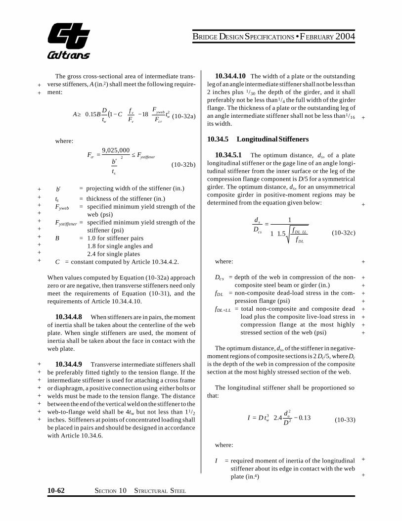
The gross cross-sectional area of intermediate transshy+ verse stiffeners A (in2) shall meet the following requireshy+ ment
Oslash D [ f ) oslash F v yweb 2ADagger Œ ( ) -18œ tw (10-32a)015B 1-C
ordm
where
+ bcent = + ts = + Fyweb = + + Fystiffener = + + B = + +
tw Ł Fv ł szlig Fcr
9025000F = pound Fcr 2 ystiffener
[ )bcent (10-32b) tsŁ ł
projecting width of the stiffener (in)
thickness of the stiffener (in) specified minimum yield strength of the web (psi) specified minimum yield strength of the stiffener (psi) 10 for stiffener pairs 18 for single angles and 24 for single plates
+ C = constant computed by Article 103442
When values computed by Equation (10-32a) approach zero or are negative then transverse stiffeners need only meet the requirements of Equation (10-31) and the requirements of Article 1034410
103448 When stiffeners are in pairs the moment of inertia shall be taken about the centerline of the web plate When single stiffeners are used the moment of inertia shall be taken about the face in contact with the web plate
+ + + + + + + +
103449 Transverse intermediate stiffeners shall be preferably fitted tightly to the tension flange If the intermediate stiffener is used for attaching a cross frame or diaphragm a positive connection using either bolts or welds must be made to the tension flange The distance between the end of the vertical weld on the stiffener to the web-to-flange weld shall be 4tw but not less than 112
inches Stiffeners at points of concentrated loading shall be placed in pairs and should be designed in accordance with Article 10346
1034410 The width of a plate or the outstanding leg of an angle intermediate stiffener shall not be less than 2 inches plus 130 the depth of the girder and it shall preferably not be less than14 the full width of the girder flange The thickness of a plate or the outstanding leg of an angle intermediate stiffener shall not be less than116
its width +
10345 Longitudinal Stiffeners
103451 The optimum distance ds of a plate longitudinal stiffener or the gage line of an angle longishytudinal stiffener from the inner surface or the leg of the compression flange component is D5 for a symmetrical girder The optimum distance ds for an unsymmetrical composite girder in positive-moment regions may be determined from the equation given below +
cs
s
D d
DL
DL LL
f f ++
= 1 15
1
(10-32c)
where +
Dc s = depth of the web in compression of the nonshycomposite steel beam or girder (in)
fDL = non-composite dead-load stress in the comshypression flange (psi)
fDL+LL = total non-composite and composite dead load plus the composite live-load stress in compression flange at the most highly stressed section of the web (psi)
+ + + + + + + +
The optimum distance ds of the stiffener in negativeshymoment regions of composite sections is 2 Dc5 whereDc
is the depth of the web in compression of the composite section at the most highly stressed section of the web
The longitudinal stiffener shall be proportioned so that
I Ł
[= 24 2
2 3
D d
D t o w
ł
)- 013 (10-33)
where
I = required moment of inertia of the longitudinal stiffener about its edge in contact with the web plate (in4)
+
+
10-62 SECTION 10 STRUCTURAL STEEL
BRIDGE DESIGN SPECIFICATIONS bull FEBRUARY 2004
+ + +
D
tw
do
= unsupported distance between flange composhynents (in)
= thickness of the web plate (in) = spacing of transverse stiffeners (in)
+ + +
103452 The width-thickness ratio (bts) of the longitudinal stiffener shall not exceed the limiting values specified in Table 10345A
103453 The stress in the stiffener shall not be greater than the basic allowable bending stress for the material used in the stiffener
+ +
TABLE 10345A Limiting Width-Thickness Ratios for Stiffeners
+
+ +
+
+ +
Description of Component Limiting (bt s)
Longitudinal and Transverse stiffeners
yF
2600 (10-34)
Bearing stiffeners
yF
2180 (10-35) amp (10-36)
Compression flange stiffeners
yF
2600 (10-88)
+ b = width of stiffener plate or outstanding legs of + angle stiffener (in) + Fy = specified minimum yield strength of stiffener + (psi) + ts = thickness of stiffener plate or outstanding legs + of angle stiffener (in)
+ 103454 Longitudinal stiffeners are usually placed + on one side only of the web plate They shall preferably + be continuous where required The termination and intershy+ section of the longitudinal stiffener with transverse atshy+ tachments shall consider the effects of fatigue The intershy+ rupted element shall maintain the same strength characshy+ teristics as an uninterrupted element
103455 For longitudinally stiffened girders transverse stiffeners shall be spaced a distance do acshycording to shear capacity as specified in Article 103442 but not more than 15 times the web depth The handling requirement given in Article 103442 shall not apply to longitudinally stiffened girders The spacing of the first
transverse stiffener at the simple support end of a longishytudinally stiffened girder shall be such that the shearing stress in the end panel does not exceed the value given in Article 103443 The total web depth D shall be used in determining the shear capacity of longitudinally stiffshyened girders in Articles 103442 and 103443
103456 Transverse stiffeners for girder panels with longitudinal stiffeners shall be designed according to Article 103447
10346 Bearing Stiffeners
103461 Welded Girders
Over the end bearings of welded plate girders and over the intermediate bearings of continuous welded plate girders there shall be stiffeners They shall extend as nearly as practicable to the outer edges of the flange plates They shall be made of plates placed on both sides + of the web plate Bearing stiffeners shall be designed as columns and their connection to the web shall be deshysigned to transmit the entire end reaction to the bearings For stiffeners consisting of two plates the column section shall be assumed to comprise the two plates and a centrally located strip of the web plate whose width is equal to not more than 18 times its thickness For stiffeners consisting of four or more plates the column section shall be assumed to comprise the four or more plates and a centrally located strip of the web plate whose width is equal to that enclosed by the four or more plates plus a width of not more than 18 times the web plate thickness (See Article 1040 for Hybrid Girders) The radius of gyration shall be computed about the axis through the centerline of the web plate The stiffeners shall be ground to fit against the flange through which they receive their reaction or attached to the flange by full penetration groove welds Only the portions of the stiffeners outside the flange-to-web plate welds shall be considered effective in bearing The width-thickness ratio (bts) of the + bearing stiffener plates shall not exceed the limiting values + specified in Table 10345A +
The allowable compressive stress and the bearing pressure on the stiffeners shall not exceed the values specified in Article 1032
SECTION 10 STRUCTURAL STEEL 10-63
BRIDGE DESIGN SPECIFICATIONS bull FEBRUARY 2004
103462 Riveted or Bolted Girders
Over the end bearings of riveted or bolted plate girders there shall be stiffener angles the outstanding legs of which shall extend as nearly as practicable to the outer edge on the flange angle Bearing stiffener angles shall be proportioned for bearing on the outstanding legs of flange angles no allowance being made for the portions of the legs being fitted to the fillets of the flange angles Bearing stiffeners shall be arranged and their connecshytions to the web shall be designed to transmit the entire end reaction to the bearings They shall not be crimped
The width-thickness ratio (bts) of the bearing stiffshyener angles shall not exceed the limiting values specified in Table 10345A
The allowable compressive stress and the bearing pressure on the stiffeners shall not exceed the values specified in Article 1032
1035 TRUSSES
10351 Perforated Cover Plates and Lacing Bars
+
The shearing force normal to the member in the planes of lacing or continuous perforated plates shall be asshysumed divided equally between all such parallel planes The shearing force shall include that due to the weight of the member plus any other external force For compresshysion members an additional shear force shall be added as obtained by the following formula
V ( )
+
+ =
3300000
10 100
100 yr Fl
rl P
(10-37)
+ where
+
+ +
+ + +
V P
l r
Fy
= normal shearing force (lb) = allowable compressive axial load on members
(lb) = length of member (in) = radius of gyration of section about the axis
perpendicular to plane of lacing or perforated plate (in)
= specified minimum yield strength of type of steel being used (psi)
10352 Compression Members +
103521 Compression members shall be so deshysigned that the main elements of the section will be connected directly to the gusset plates pins or other members
103522 The center of gravity of a built-up secshytion shall coincide as nearly as practicable with the center of the section Preferably segments shall be connected by solid webs or perforated cover plates
103523 The with-thickness ratio (bt) of eleshyments of compression members shall not exceed the limiting values specified in Table 10352A
+ + +
103524 Deleted +
103525 Deleted +
103526 Deleted +
103527 Deleted +
103528 Deleted +
103529 Deleted +
1035210 Deleted +
1035211 Deleted +
10-64 SECTION 10 STRUCTURAL STEEL
BRIDGE DESIGN SPECIFICATIONS bull FEBRUARY 2004
+
+
+
+
+ + + + +
+ + + + + +
+ + + + + +
+ + + + + +
+ + + +
+ + + + +
TABLE 10352A Limiting Width-Thickness Ratios for Compression Member Elements
Description of Component Limiting (bt) When f a
= 044 F y
F y(psi)
Limiting bt
Plates supported on one side outstanding legs of angles and perforated platesndashfor outstanding plates outstanding legs of angles and perforated plates at the perforations (10-38)
le for secondary member16
12 for main members1625
af
36000 50000 70000 90000 100000
12 11 9 8
75
Plates supported on two edges or webs of main component segments ndashfor members of box shape consisting of main plates rolled sections or made up component segments with cover plates
(10-39)454000
le af
36000 50000 70000 90000 100000
32 27 23 20 19
Solid cover plates supported on two edges or webs connecting main members or segmentsndashfor members of H or box shapes consisting of solid cover plates or solid webs connecting main plates or segments
(10-40)505000
le af
36000 50000 70000 90000 100000
40 34 28 25 24
Perforated cover plates supported on two edgesndashfor members of box shapes consisting of perforated cover plates connecting main plates or segments perforated cover plates supported on one side
(10-41)556000
le af
36000 50000 70000 90000 100000
48 41 34 30 29
b = distance between points of support (in) fa = calculated compressive stress in the component under consideration (psi) Fy = specified minimum yield strength of the component under consideration (psi) t = component plate thickness (in)
Note The point of support shall be the inner line of fasteners or fillet welds connecting the plate to the main segment For plates butt welded to the flange edge of rolled segments the point of support may be taken as the weld whenever the ratio of outstanding flange width to flange thickness of the rolled segment is less than seven Otherwise point of support shall be the root of flange of rolled segment Terminations of the butt welds are to be ground smooth
SECTION 10 STRUCTURAL STEEL 10-65
BRIDGE DESIGN SPECIFICATIONS bull FEBRUARY 2004
1036 COMBINED STRESSES
All members subjected to both axial compression and + flexure shall be proportioned to satisfy the following
requirements
fa +Fa
and
fa
0472 yF
where
+ fa
+ fbx fby
+ + Fa
+ + Fbx Fby
+
+ Fe
+ + E
Kb
+ Lb
rb
+ Cmx Cmy
FS
Cmx fbx Cmy fby+ le 10
f fa a1minus Fbx 1minus Fby
(10-42)F prime prime ex Fey
f fbx by+ + le 10 (at points of support)F Fbx by
(10-43)
π 2 EFe prime = )2 (10-44)FS(K L rb b b
= calculated axial stress (psi) = calculated compressive bending stress
about the x axis and y axis respectively (psi)
= allowable axial if axial force alone exists regardless of the plane of bending (psi)
= allowable compressive bending stress if bending moment alone exists about the x axis and the y axis respectively as evalushyated according to Table 10321A (psi)
= Euler buckling stress divided by a factor of safety (psi)
= modulus of elasticity of steel (psi) = effective length factor in the plane of
bending (see Appendix C) = actual unbraced length in the plane of
bending (in) = radius of gyration in the plane of bending
(in) = coefficient about the x axis and y axis
respectively whose value is taken from Table 1036A
= factor of safety = 212
10-66 SECTION 10 STRUCTURAL STEEL
BRIDGE DESIGN SPECIFICATIONS bull FEBRUARY 2004
+
+ +
+ +
TABLE 1036A Bending-Compression Interaction Coeffcients
Loading Conditions Remarks Cm
Computed moments maximum at end joint translation 085p p not prevented
r
Computed moments maximum at end no transverseloading joint translation prevented
( )
+ 0604
2
1
M M
r p
p
Transverse loading joint translation prevented 085r
p
p
p pTransverse loading joint translation prevented 10
r
M1 = smaller end moment M1M2 is positive when member is bent in single curvature M1M2 is negative when member is bent in reverse curvature In all cases Cm may be conservatively taken equal to 10
1037 SOLID RIB ARCHES
2
2
=
r KL
EFe
π
(10-46)
10371 Moment Amplification and Allowable Stress
103711 The calculated compressive bending stress due to live load plus impact loading that are determined by an analysis which neglects arch rib deflecshytion shall be increased by an amplification factor AF
e
F
A F TA
171
1
minus =
(10-45)
L = one half of the length of the arch rib (in) A = area of cross section (in2) r = radius of gyration (in) K = effective length factor of the arch rib
K Values for Use in Calculating Fe and Fa
Rise to Span 3-Hinged 2-Hinged Fixed Ratio Arch Arch Arch
01 - 02 116 104 070
where
T = arch rib thrust at the quarter point from dead plus live plus impact loading (lb)
Fe = Euler buckling stress (psi)
02 - 03 113 110 070
03 - 04 116 116 072
+
+
+
SECTION 10 STRUCTURAL STEEL 10-67
BRIDGE DESIGN SPECIFICATIONS bull FEBRUARY 2004
103712 The arch rib shall be proportioned to 103723 If two longitudinal stiffeners are used at satisfy the following requirement the one-third points of the web depth D the moment of
inertia of each stiffener shall meet the following require- + fa
Fa
+ ment +fb le 10 (10-47)Fb
I s ge 22Dtw 3 (10-53) +
where
+ fa = the calculated axial stress (psi) + fb = the calculated bending stress including moshy+ ment amplification at the extreme fiber (psi) + Fa = the allowable axial stress (psi) + Fb = the allowable bending stress (psi)
103713 For buckling in the vertical plane
103724 The width-thickness ratio (bts) of any outstanding element of the web stiffeners shall not exshyceed the limiting values specified in Table 10372A +
103725 Deleted +
10373 Flange Plates
The width-thickness ratio (btf) of flange plates shall not + +exceed the limiting values specified in Table 10372A
2
Fy
K L
2π
Fa = Fy
FS103731 Deleted +
103732 Deleted +
r1minus4 E (10-48)
+ where KL as defined above and FS is factor of safety = + 212
103714 The effects of lateral slenderness should be investigated Tied arch ribs with the tie and roadway suspended from the rib are not subject to moment amplishyfication and Fa shall be based on an effective length equal to the distance along the arch axis between susshypenders for buckling in the vertical plane However the smaller cross-sectional area of cable suspenders may result in an effective length slightly longer than the distance between suspenders
10372 Web Plates
+ 103721 The width-thickness ratio (Dtw) of the + web plates shall not exceed the limiting values specified + in Table 10372A
103722 If one longitudinal stiffener is used at mid-depth of the web the moment of inertia of the stiffener about an axis parallel to the web and at the base
+ of the stiffener shall meet the following requirement
+ I s ge 075Dtw 3 (10-51)
10-68 SECTION 10 STRUCTURAL STEEL
BRIDGE DESIGN SPECIFICATIONS bull FEBRUARY 2004
TABLE 10372A Limiting Width-Thickness Ratios for Solid Rib Arches +
Web Plates
Flange Plates
b = fa = fb = tf = ts = tw =
Description of Component
Without longitudinal stiffiners
With one longitudinal stiffener at the one-third point of the web depth
With two longitudinal stiffeners at the one-third point of the web design
Outstanding element of stiffiners
Web plate equations apply between limits
Plates between webs
Overhang plates
Width +Thickness Limiting Width-Thickness Ratio
Ratio
5000 +pound 60 (10-49)fa
7500 pound 90 (10-50) +D t w fa
10000 pound 120 (10-52) +fa
1625 pound 12 (10-54)b tcent +s fa + fb 3
fb02 pound pound 07 +(10-55)fa + fb 3
4250 pound 47 (10-56) +
fa + fb
centb t f 1625 (10-57)
fa + fb
pound 12 +
width of flange plate or width of outstanding element of web stiffeners (in) + calculated axial compressive stress in the component under consideration (psi) + calculated compressive bending stress in the component under consideration (psi) + flange plate thickness (in) + web stiffener outstanding element thickness (in) + web plate thickness (in) +
SECTION 10 STRUCTURAL STEEL 10-69
BRIDGE DESIGN SPECIFICATIONS bull FEBRUARY 2004
+ 1038 COMPOSITE BEAMS AND GIRDERS +
10381 General
+ 103811 This section pertains to structures comshy
posed of steel beams or girders with concrete slabs connected by shear connectors
103812 General specifications pertaining to the design of concrete and steel structures shall apply to strucshytures utilizing composite girders where such specifications are applicable Composite girders and slabs shall be deshysigned and the stresses computed by the composite moment of inertia method and shall be consistent with the predetershymined properties of the various materials used
+ 103813 The ratio of the modulus of elasticity of steel (29000000 psi) to those of normal weight concrete (W = 145 pcf) of various design strengths shall be as follows
+
+
+
f c
n
f c
= specified compressive strength of concrete as determined by cylinder tests at the age of 28 days (psi)
= ratio of modulus of elasticity of steel to that of concrete The value of n as a function of the specified compressive strength of concrete shall be assumed as follows
= 2000 - 2300 n = 11 2400 - 2800 n = 10 2900 - 3500 n = 9 3600 - 4500 n = 8 4600 - 5900 n = 7 6000 or more n = 6
+ +
+
103814 The effect of creep shall be considered in the design of composite girders which have dead loads acting on the composite section In such structures bendshying stresses and horizontal shears produced by dead loads acting on the composite section shall be computed for n as given above or for this value multiplied by 3 whichshyever gives the higher bending stresses and shears
103815 If concrete with expansive characterisshytics is used composite design should be used with caushytion and provision must be made in the design to accomshymodate the expansion
103816 Composite sections in simple spans and the positive moment regions of continuous spans should
preferably be proportioned so that the neutral axis lies below the top surface of the steel beam Concrete on the tension side of the neutral axis shall not be considered in calculating resisting moments In the negative moment regions of continuous spans only the slab reinforcement can be considered to act compositely with the steel beams in calculating resisting moments Mechanical anchorshyages shall be provided in the composite regions to deshyvelop stresses on the plane joining the concrete and the steel Concrete on the tension side of the neutral axis may be considered in computing moments of inertia for deshyflection calculations for determining stiffness used in + calculating moments and shears and for computing fashytigue stress ranges and fatigue shear ranges as permitted under the provisions of Article1031and 103851
103817 The steel beams or girders especially if not supported by intermediate falsework shall be invesshytigated for stability and strength for the loading applied during the time the concrete is in place and before it has hardened The casting or placing sequence specified in the plans for the composite concrete deck shall be considshyered when calculating the moments and shears on the steel section The maximum flange compression stress shall not exceed the value specified in Table 10321A for partially supported or unsupported compression flanges multiplied by a factor of 14 but not exceed 055Fy The sum of the non-composite and composite dead-load shear stresses in the web shall not exceed the shear-buckling capacity of the web multiplied by a factor of 135 nor the allowable shear stress as follows
Fv = 045CFy le 033Fy (10-57a)
where
+C = constant specified in Article 103442
10382 Shear Connectors
103821 The mechanical means used at the juncshytion of the girder and slab for the purpose of developing the shear resistance necessary to produce composite action shall conform to the specifications of the respecshytive materials The shear connectors shall be of types that + permit a thorough compaction of the concrete in order to ensure that their entire surfaces are in contact with the concrete They shall be capable of resisting both horizonshytal and vertical movement between the concrete and the steel
10-70 SECTION 10 STRUCTURAL STEEL
BRIDGE DESIGN SPECIFICATIONS bull FEBRUARY 2004
103822 The capacity of stud and channel shear connectors welded to the girders is given in Article 10385 Channel shear connectors shall have at least 316-inch fillet welds placed along the heel and toe of the channel
103823 The clear depth of concrete cover over the tops of the shear connectors shall be not less than 2 inches Shear connectors shall penetrate at least 2 inches above bottom of slab
103824 The clear distance between the edge of a girder flange and the edge of the shear connectors shall be not less than 1 inch Adjacent stud shear connectors shall not be closer than 4 diameters center to center
10383 Effective Flange Width
103831 In composite girder construction the asshysumed effective width of the slab as a T-beam flange shall not exceed the following
(1) One-fourth of the span length of the girder (2) The distance center to center of girders (3) Twelve times the least thickness of the slab
103832 For girders having a flange on one side only the effective flange width shall not exceed oneshytwelfth of the span length of the girder or six times the thickness of the slab or one-half the distance center to center of the next girder
10384 Stresses
103841 Maximum compressive and tensile stresses in girders that are not provided with temporary supports during the placing of the permanent dead load shall be the sum of the stresses produced by the dead loads acting on the steel girders alone and the stresses produced by the superimshyposed loads acting on the composite girder When girders are provided with effective intermediate supports that are kept in place until the concrete has attained 75 percent of its required 28-day strength the dead and live load stresses shall be computed on the basis of the composite section
103842 A continuous composite bridge may be built with shear connectors either in the positive moment regions or throughout the length of the bridge The positive moment regions may be designed with composshyite sections as in simple spans Shear connectors shall be
provided in the negative moment portion in which the reinforcement steel embedded in the concrete is considshyered a part of the composite section In case the reinforceshyment steel embedded in the concrete is not used in computing section properties for negative moments shear connectors need not be provided in these portions of the spans but additional anchorage connectors shall be placed in the region of the point of dead load contra-flexure in accordance with Article 1038513 Shear connectors shall be provided in accordance with Article 10385
103843 The minimum longitudinal reinforceshyment including the longitudinal distribution reinforceshyment must equal or exceed one percent of the crossshysectional area of the concrete slab whenever the longitushydinal tensile stress in the concrete slab due to either the construction loads or the design loads exceeds f specifiedt in Article 815211 The area of the concrete slab shall be equal to the structural thickness times the entire width of the bridge deck The required reinforcement shall be No 6 bars or smaller spaced at not more than 12 inches Two-thirds of this required reinforcement is to be placed in the top layer of slab Placement of distribution steel as specified in Article 32410 is waived
103844 When shear connectors are omitted from the negative moment region the longitudinal reinforceshyment shall be extended into the positive moment region beyond the anchorage connectors at least 40 times the reinforcement diameter For epoxy-coated bars the length to be extended into the positive moment region beyond the anchorage connectors should be modified to comply with Article 82523
10385 Shear
103851 Horizontal Shear
The maximum pitch of shear connectors shall not exceed 24 inches except over the interior supports of continuous beams where wider spacing may be used to avoid placing connectors at locations of high stresses in the tension flange
Resistance to horizontal shear shall be provided by meshychanical shear connectors at the junction of the concrete slab and the steel girder The shear connectors shall be mechanical devices placed transversely across the flange
SECTION 10 STRUCTURAL STEEL 10-71
BRIDGE DESIGN SPECIFICATIONS bull FEBRUARY 2004
of the girder spaced at regular or variable intervals The shear connectors shall be designed for fatigue and
+ checked for design strength
1038511 Fatigue
The range of horizontal shear shall be computed by the formula
VrQSr = (10-58)I
where
+ Sr = range of horizontal shear (lbin) at the junction of the slab and girder at the point in the span under consideration
+ Vr = range of shear due to live loads and impact (lb) at any section the range of shear shall be taken as the difference in the minimum and maximum shear envelopes (excluding dead loads)
Q = statical moment about the neutral axis of the composite section of the transformed concrete
+ area (in3) Between points of dead-load contraflexure the static moment about the neushytral axis of the composite section of the area of reinforcement embedded in the concrete may be used unless the transformed concrete area is considered to be fully effective for the negative moment in computing the longitudinal ranges of stress
+ I = moment of inertia of the transformed short-term + composite section (in4) Between points of deadshy
load contraflexure the moment of inertia of the steel girder including the area of reinforcement embedded in the concrete may be used unless the transformed concrete area is considered to be fully effective for the negative moment in
+ computing the longitudinal ranges of stress
+ (In the formula the concrete area is transformed into an equivalent area of steel by dividing the effective concrete flange width by the modular ratio n)
Reference is made to the paper titled ldquoFatigue Strength of Shear Connectorsrdquo by Roger G Slutter and John W Fisher in Highway Research Record No 147 published by the Highway Research Board Washington DC 1966
The allowable range of horizontal shear Zr (lb) on an + individual connector is as follows
Channels
Zr = Bw (10-59)
Welded studs (for Hd ge 4)
Zr = α d2 (10-60)
where
w = length of a channel shear connector (in) mea- + sured in a transverse direction on the flange of a girder
d = diameter of stud (in) + α = 13000 for 100000 cycles +
10600 for 500000 cycles 7850 for 2000000 cycles 5500 for over 2000000 cycles
B = 4000 for 100000 cycles 3000 for 500000 cycles 2400 for 2000000 cycles 2100 for over 2000000 cycles
H = height of stud (in) +
The required pitch of shear connectors is determined by dividing the allowable range of horizontal shear of all connectors at one transverse girder cross-section (ΣZr) by the horizontal range of shear Sr but not to exceed the maximum pitch specified in Article 103851 Over the interior supports of continuous beams the pitch may be modified to avoid placing the connectors at locations of high stresses in the tension flange provided that the total number of connectors remains unchanged
1038512 Design Strength +
The number of connectors so provided for fatigue shall be checked to ensure that adequate connectors are provided for design strength +
10-72 SECTION 10 STRUCTURAL STEEL
BRIDGE DESIGN SPECIFICATIONS bull FEBRUARY 2004
+ The number of shear connectors required shall meet + the following requirement
PN1 Dagger (10-61)f Su
where
N1 = number of connectors between points of maxishymum positive moment and adjacent end supports
+ Su = design strength of the shear connector as given + below (lb)
f = reduction factor = 085 + P = horizontal shear force transferred by shear conshy+ nectors as defined hereafter as P1 or P2
At points of maximum positive moment the force in the slab is taken as the smaller value of the formulas
P1 = AsFy (10-62)
or
P = 085 f centbt (10-63)2 c s
where
As = total area of the steel section including cover shy+ plates (in2) + Fy = specified minimum yield strength of the steel + being used (psi) + fc
cent = specified compressive strength of concrete at + age of 28 days (psi) + b = effective flange width given in Article 10383 (in) + ts = thickness of the concrete slab (in)
The number of connectors N2 required between the points of maximum positive moment and points of adjashy
+ cent maximum negative moment shall meet the followshy+ ing requirement
P + PN Dagger 3
2 (10-64)f Su
At points of maximum negative moment the force in the slab is taken as
r rP3 = As Fy (10-65)
where
Asr = total area of longitudinal reinforcing steel at
the interior support within the effective flange width (in2) +
F r y = specified minimum yield strength of the rein- +
forcing steel (psi) +
The design strength of the shear connector is given + as follows Channels
[ t ) centSu = 550 h+ W fc (10-66)Ł 2 ł
Welded studs (for Hd gt 4)
S = 04 d 2 f c E pound 60000A (10-67)u c sc
where
Ec = modulus of elasticity of the concrete (psi) + Ec = w
3 233 f ccent (10-68)
Su = design strength of individual shear connector + (lb) +
h = average flange thickness of the channel flange (in) +
t = thickness of the web of a channel (in) + W = length of a channel shear connector (in) + fc cent = specified compressive strength of the concrete
at 28 days (psi) + d = diameter of stud (in) + w = unit weight of concrete (pcf) + Asc = area of welded stud cross section (in2) +
SECTION 10 STRUCTURAL STEEL 10-73
BRIDGE DESIGN SPECIFICATIONS bull FEBRUARY 2004
1038513 Additional Connectors to Develop Slab Stresses
The number of additional connectors required at points of contraflexure when reinforcing steel embedded in the concrete is not used in computing section propershyties for negative moments shall be computed by the formula
cN = r
r s r
Z A f
(10-69)
where
Nc = number of additional connectors for each beam at point of contraflexure
+ s rA = total area of longitudinal slab reinforcing steel
for each beam over interior support (in2) + fr = range of stress due to live load plus impact in
the slab reinforcement over the support (psi) (in lieu of more accurate computations fr may be taken as equal to 10000 psi)
+ Zr = allowable range of horizontal shear on an individual shear connector (lb)
The additional connectorsNc shall be placed adjacent to the point of dead load contraflexure within a distance equal to one-third the effective slab width ie placed either side of this point or centered about it It is prefershyable to locate field splices so that they clear the connecshytors
+ 103852 Vertical Shear
The intensity of shearing stress in a composite girder may be determined on the basis that the web of the steel girder carries the total external shear neglecting the effects of the steel flanges and of the concrete slab The shear may be assumed to be uniformly distributed throughout the gross area of the web
10386 Deflection
103861 The provisions of Article 106 in regard to deflections from live load plus impact also shall be applicable to composite girders
103862 When the girders are not provided with falsework or other effective intermediate support during
the placing of the concrete slab the deflection due to the weight of the slab and other permanent dead loads added before the concrete has attained 75 percent of its required 28-day strength shall be computed on the basis of noncomposite action
1039 COMPOSITE BOX GIRDERS
10391 General
103911 This section pertains to the design of simple and continuous bridges of moderate length supshyported by two or more single cell composite box girders The distance center-to-center of flanges of each box should be the same and the average distance center-toshycenter of flanges of adjacent boxes shall be not greater than 12 times and not less than 08 times the distance center-to-center of flanges of each box In addition to the above when nonparallel girders are used the distance center-to-center of adjacent flanges at supports shall be no greater than 135 times and not less than 065 times the distance center-to-center of flanges of each box The cantilever overhang of the deck slab including curbs and parapets shall be limited to 60 percent of the average distance center-to-center of flanges of adjacent boxes but shall in no case exceed 6 feet +
103912 The provisions of these Specifications shall govern where applicable except as specifically modified by Articles 10391 through 10398
10392 Lateral Distribution of Loads for Bending Moment
103921 The live load bending moment for each box girder shall be determined by applying to the girder the fraction WL of a wheel load (both front and rear) determined by the following equation
085WL = 01 + 17 R + (10-70)Nw
where
N wR = (10-71)Numberof Box Girders
10-74 SECTION 10 STRUCTURAL STEEL
BRIDGE DESIGN SPECIFICATIONS bull FEBRUARY 2004
Nw = Wc12 reduced to the nearest whole number + Wc = roadway width between curbs (ft) or barriers
if curbs are not used
+ R shall not be less than 05 or greater than 15
103922 The provision of Article 312 Reducshytion of Load Intensity shall not apply in the design of box girders when using the design load WL given by the above equation
+ 10393 Web Plates
103931 Vertical Shear
The design shear Vw for a web shall be calculated using the following equation
VvVw =
10394 Bottom Flange Plates +
103941 General +
The tension flange and the compression flange shall + be considered completely effective in resisting bending if + its width does not exceed one-fifth the span length If the + flange plate width exceeds one-fifth of the span an + amount equal to one-fifth of the span only shall be + considered effective Effective flange plate width shall + be used to calculate the flange bending stress Full flange + plate width shall be used to calculate the allowable + compressive bending stress
1039412 Deleted +
103942 Compression Flanges Unstiffened
1039421 For unstiffened compression flanges + (10-72) the calculated bending stress shall not exceed the allow- +cosθ
able bending stress Fb (psi) determined by either of the + following equations +
where
b
t F
6140 +le+ Vv = vertical shear (lb) for
θ = angle of inclination of the web plate to the vertical
y
Fb = 055 Fy (10-73) + 103932 Secondary Bending Stresses
+
yy Ft b
F
6140 13300lelt1039321 Web plates may be plumb (90deg to botshy for
tom of flange) or inclined If the inclination of the web plates to a plane normal to bottom flange is no greater than 1 to 4 and the width of the bottom flange is no greater than 20 percent of the span the transverse bendshy b Fy
t
minus13300
2 7160
ing stresses resulting from distortion of the span and the transverse bending stresses resulting from distortion of
πFb 055Fy 0224 Fyminus minussin= + the girder cross section and from vibrations of the bottom plate need not be considered For structures in this catshyegory transverse bending stresses due to supplementary
1
(10-74)loadings such as utilities shall not exceed 5000 psi
b 13300 +ge
t Ffor1039322 For structures exceeding these limits a y
detailed evaluation of the transverse bending stresses due to all causes shall be made These stresses shall be limited
2to a maximum stress or range of stress of 20000 psi
t times106 (10-75) +Fb = 576
b
SECTION 10 STRUCTURAL STEEL 10-75
BRIDGE DESIGN SPECIFICATIONS bull FEBRUARY 2004
where+
+ b = flange width between webs (in) + t = flange thickness (in)
1039422 Deleted+
1039423 Deleted+
1039424 The bt ratio preferably should not exshyceed 60 except in areas of low stress near points of dead load contraflexure
+ 1039425 If the bt ratio exceeds 45 longitudinal + stiffeners may be considered
+ 1039426 Deleted
103943 Compression Flanges Stiffened Longitudinally
1039431 Longitudinal stiffeners shall be at equal spacings across the flange width and shall be proporshytioned so that the moment of inertia of each stiffener about an axis parallel to the flange and at the base of the
+ stiffener Is (in4) shall meet the following requirement
+ I s ge φ t3 f w (10-76)
where
φ = 007 k3n4 for values of n greater than 1 + φ = 0125 k3 for a value of n = 1
tf = thickness of the flange (in) w = width of flange between longitudinal stiffeners
+ or distance from a web to the nearest longitudishynal stiffener (in)
n = number of longitudinal stiffeners k = buckling coefficient which shall not exceed 4
+ 1039432 For the longitudinally stiffened flange + including stiffeners the calculated bending stress shall + not exceed the allowable bending stress Fb (psi) detershy+ mined by either of the following equations
w 3070 kle+ for t Fy
In solving these equations a value of k between 2 and 4 generally should be assumed
F = 055 Fb y
3070 k w for Fy
lt le smaller of 60 or t
w
Fb = 055Fy
minus0224 Fy 1minussin
6650 k minus
2 3580 π
k t
y
+
(10-78)
for 6650
Fy
k le
t w le 60
+
Fb t
2 6= 144 k times10 (10-79) +
+1039433 Deleted
+1039434 Deleted
1039435 When longitudinal stiffeners are used it is preferable to have at least one transverse stiffener placed near the point of dead load contraflexure The stiffener should have a size equal to that of a longitudinal stiffener
1039436 If the longitudinal stiffeners are placed at their maximum wt ratio to be designed for the basic allowable design stresses of 055Fy and the number of longitudinal stiffeners exceeds 2 then transverse stiffenshyers should be considered
1039437 Deleted +
(10-77) +
6650 k + F y
w F
10-76 SECTION 10 STRUCTURAL STEEL
0
BRIDGE DESIGN SPECIFICATIONS bull FEBRUARY 2004
100
90
80
70
60
50
Is bt
40
0
0
10
0
k = 4 k = 4 k = 4
=
4
Ffr = Fy
Ffr = 096 Fy
NO STbtbb = 055 Fy
bbb = 05 Fy
IFFENERS REQUIRED
Fy = 6140
Fy = 0800
=
4
=4
Ffr = 085 Fy
t btbb = 047 Fy Fy = 10060
Note Ffr refebb refersFy is in
rs to Load Factor to Working Stres
1bin
Design s Design
=
k = 56
=
k = 56 k
=
= 56
b b =
05
5 F y
F fr =
Fy
b b =
05
F y
fr =
09
6 F y
F y y
WITHOUT TRANSVERSE STIFFENERS
F
b b =
047
F f
r = 0
85 F
k = 4 k = 4 k = 4
k = 5
= k = 5
=
=
k = 5 WITSH TRANSVERSE TIFFENERS
k
= 1
k = 4= 178
k = 4 = 1
= 1
k = 178
k = 4
k = 178
= = = =
Is = 67bt Is = 00bt 4 Is = 160bt 5 Is = 1bt
5000 10000 15000 0000 5000 0000 5000 40000
b Fyt
FIGURE 103943A Longitudinal StiffenersntildeBox Girder Compression Flange
SECTION 10 STRUCTURAL STEEL 10-77
BRIDGE DESIGN SPECIFICATIONS bull FEBRUARY 2004
3
2 5
2
a b
1 5
1
0 5
0
( fs 0 47 Fy) (Fs 0 85 Fy)
b t
Fy
Is for longitudinal stiffeners 8 t3w (in 4)
k1 4 k1 2 25
k1 2 25k1 4
k1 2 5 k1 4
k1 1 78
k1 1 78
k1 2 78k1 4
2
5
5
4
4
4
3
3
3
2
2
2
3
3
4
3
4 4
5 5 k1 4k1 2 78
k1 2 5
k1 4
k1 2
2
2
Note fs refers to Working Stress Design Fs refers to Load Factor Design Fy is in lbin 2
a b
( fs 0 47 Fy) (Fs 0 85 Fy)
a b
( fs 0 55 Fy) (Fs Fy)
a b ( fs 0 53 Fy) (Fs 0 9 Fy)
It b f Fy
It b f Fy
( fs 0 53 Fy) (Fs 0 9 Fy)
It b f Fy
( fs 0 55 Fy) (Fs Fy)
k1 4
0 09
0 08
0 07
0 0
0 05
0 04
It b f Fy
0 03
0 02
0 01
10000 15000 20000 25000 30000 35000 40000 45000
FIGURE 103943B Spacing and Size of Transverse Stiffeners (for Flange Stiffened Longitudinally and Transversely)
10-78 SECTION 10 STRUCTURAL STEEL
0
BRIDGE DESIGN SPECIFICATIONS bull FEBRUARY 2004
103944 Compression Flanges Stiffened Longitudinally and Transversely
1039441 The longitudinal stiffeners shall be at equal spacings across the flange width and shall be proportioned so that the moment of inertia of each stiffshyeners about an axis parallel to the flange and at the base
+ of the stiffeners meet the following requirement
I s ge 8t3 f w (10-80)
1039442 The transverse stiffeners shall be proshyportioned so that the moment of inertia of each stiffener about an axis through the centroid of the section and parallel
+ to its bottom edge meets the following requirement
3 3 fs Af+ It ge 010 (n + 1) w (10-81)E do
where
Af = area of bottom flange including longitudinal + stiffeners (in2) + do = spacing of transverse stiffeners (in)
fs = maximum longitudinal bending stress in the flange of the panels on either side of the transshy
+ verse stiffeners (psi) + E = modulus of elasticity of steel (psi)
+ 1039443 For the flange including stiffeners the + calculated bending stress shall not exceed the allowable + bending stress Fb (psi) determined by either of the + following equations
w 3070 k1+ lefor t Fy
+ Fb = 055 Fy (10-82)
3070 k1 w 6650 k1 le or + lt smaller of 60for Fy t F y
w F 6650 k1 minus y
π t F = 055F minus0224 F 1minussinb y y + 2 3580 k1
(10-83)
6650 k1 wle le 60 +for Fy t
t 2
6Fb = 144 k1 times10 (10-84) + w
where
( ) [ ( ) ( ) 1
1 22
2
1 +
+ =
a bn
a bk ]
( ) [ 1 ]011 873
2
++
+
n (10-85) +
1039444 Deleted +
1039445 Deleted +
1039446 The maximum value of the buckling coefficient k1 shall be 4 When k1 has its maximum value the transverse stiffeners shall have a spacing a equal to or less than 4w If the ratio ab exceeds 3 transverse stiffeners are not necessary
1039447 The transverse stiffeners need not be connected to the flange plate but shall be connected to the webs of the box and to each longitudinal stiffener The connection to the web shall be designed to resist the vertical force determined by the formula
R = FySs
w (10-86)2 b
where
Ss = section modulus of the transverse stiffener (in3) +
SECTION 10 STRUCTURAL STEEL 10-79
BRIDGE DESIGN SPECIFICATIONS bull FEBRUARY 2004
1039448 The connection to each longitudinal stiffener shall be designed to resist the vertical force determined by the formula
F S =Rs n
y
bs
(10-87)
103945 Compression Flange Stiffeners General
+ 1039451 The width-thickness ratio (bts) of any outstanding element of the flange stiffeners shall not
+ exceed the limiting values specified in Table 10345A
1039452 Longitudinal stiffeners shall be exshytended to locations where the maximum stress in the flange does not exceed that allowed for base metal adjacent to or connected by fillet welds
+ 10395 Flange to Web Welds
The total effective thickness of the web-flange welds + shall be not less than the thickness of the web Regardless
of the type weld used welds shall be deposited on both sides of the connecting flange or web plate
10396 Diaphragms
103961 Diaphragms cross-frames or other means shall be provided within the box girders at each support to resist transverse rotation displacement and distortion
103962 Intermediate diaphragms or cross-frames are not required for steel box girder bridges designed in accordance with this specification
10397 Lateral Bracing
Generally no lateral bracing system is required beshytween box girders A horizontal wind load of 50 pounds per square foot shall be applied to the area of the supershystructure exposed in elevation Half of the resulting force shall be applied in the plane of the bottom flange The section assumed to resist the horizontal load shall consist of the bottom flange acting as a web and 12 times the thickness of the webs acting as flanges A lateral bracing system shall be provided if the combined stresses due to the specified horizontal force and dead load of steel and deck exceed 150 percent of the allowable design stress
10398 Access and Drainage
Consistent with climate location and materials considshyeration shall be given to the providing of manholes or other openings either in the deck slab or in the steel box for form removal inspection maintenance drainage etc
1040 HYBRID GIRDERS
10401 General
104011 This section pertains to the design of girders that utilize a lower strength steel in the web than in one or both of the flanges It applies to composite and noncomposite plate girders and composite box girders At any cross section where the bending stress in either flange exceeds 55 percent of minimum specified yield strength of the web steel the compression-flange area shall not be less than the tension-flange area The top-flange area shall include the transformed area of any portion of the slab or reinforcing steel that is considered to act compositely with the steel girder
104012 The provisions of these Specifications shall govern where applicable except as specifically modified by Articles 10401 through 10404
+
10402 Allowable Stresses
104021 Bending
1040211 The bending stress in the web may exceed the allowable stress for the web steel provided that the stress in each flange does not exceed the allowshyable stress from Articles 103 or 1032 for the steel in that flange multiplied by the reduction factor R
( ) ( ) ( ψ )βψ
ψαψαβψ minus+
+minusminusminus=
36 31
1 2
R (10-89)
(See Figures 104021A and 104021B)
where
α = specified minimum yield strength of the web divided by the specified minimum yield strength of the tension flange
β = area of the web divided by the area of the tension flange
Bottom flange of orthotropic deck bridge
+
10-80 SECTION 10 STRUCTURAL STEEL
BRIDGE DESIGN SPECIFICATIONS bull FEBRUARY 2004
The gross cross-sectional area of intermediate transshy+ verse stiffeners A (in2) shall meet the following requireshy+ ment
Oslash D [ f ) oslash F v yweb 2ADagger Œ ( ) -18œ tw (10-32a)015B 1-C
ordm
where
+ bcent = + ts = + Fyweb = + + Fystiffener = + + B = + +
tw Ł Fv ł szlig Fcr
9025000F = pound Fcr 2 ystiffener
[ )bcent (10-32b) tsŁ ł
projecting width of the stiffener (in)
thickness of the stiffener (in) specified minimum yield strength of the web (psi) specified minimum yield strength of the stiffener (psi) 10 for stiffener pairs 18 for single angles and 24 for single plates
+ C = constant computed by Article 103442
When values computed by Equation (10-32a) approach zero or are negative then transverse stiffeners need only meet the requirements of Equation (10-31) and the requirements of Article 1034410
103448 When stiffeners are in pairs the moment of inertia shall be taken about the centerline of the web plate When single stiffeners are used the moment of inertia shall be taken about the face in contact with the web plate
+ + + + + + + +
103449 Transverse intermediate stiffeners shall be preferably fitted tightly to the tension flange If the intermediate stiffener is used for attaching a cross frame or diaphragm a positive connection using either bolts or welds must be made to the tension flange The distance between the end of the vertical weld on the stiffener to the web-to-flange weld shall be 4tw but not less than 112
inches Stiffeners at points of concentrated loading shall be placed in pairs and should be designed in accordance with Article 10346
1034410 The width of a plate or the outstanding leg of an angle intermediate stiffener shall not be less than 2 inches plus 130 the depth of the girder and it shall preferably not be less than14 the full width of the girder flange The thickness of a plate or the outstanding leg of an angle intermediate stiffener shall not be less than116
its width +
10345 Longitudinal Stiffeners
103451 The optimum distance ds of a plate longitudinal stiffener or the gage line of an angle longishytudinal stiffener from the inner surface or the leg of the compression flange component is D5 for a symmetrical girder The optimum distance ds for an unsymmetrical composite girder in positive-moment regions may be determined from the equation given below +
cs
s
D d
DL
DL LL
f f ++
= 1 15
1
(10-32c)
where +
Dc s = depth of the web in compression of the nonshycomposite steel beam or girder (in)
fDL = non-composite dead-load stress in the comshypression flange (psi)
fDL+LL = total non-composite and composite dead load plus the composite live-load stress in compression flange at the most highly stressed section of the web (psi)
+ + + + + + + +
The optimum distance ds of the stiffener in negativeshymoment regions of composite sections is 2 Dc5 whereDc
is the depth of the web in compression of the composite section at the most highly stressed section of the web
The longitudinal stiffener shall be proportioned so that
I Ł
[= 24 2
2 3
D d
D t o w
ł
)- 013 (10-33)
where
I = required moment of inertia of the longitudinal stiffener about its edge in contact with the web plate (in4)
+
+
10-62 SECTION 10 STRUCTURAL STEEL
BRIDGE DESIGN SPECIFICATIONS bull FEBRUARY 2004
+ + +
D
tw
do
= unsupported distance between flange composhynents (in)
= thickness of the web plate (in) = spacing of transverse stiffeners (in)
+ + +
103452 The width-thickness ratio (bts) of the longitudinal stiffener shall not exceed the limiting values specified in Table 10345A
103453 The stress in the stiffener shall not be greater than the basic allowable bending stress for the material used in the stiffener
+ +
TABLE 10345A Limiting Width-Thickness Ratios for Stiffeners
+
+ +
+
+ +
Description of Component Limiting (bt s)
Longitudinal and Transverse stiffeners
yF
2600 (10-34)
Bearing stiffeners
yF
2180 (10-35) amp (10-36)
Compression flange stiffeners
yF
2600 (10-88)
+ b = width of stiffener plate or outstanding legs of + angle stiffener (in) + Fy = specified minimum yield strength of stiffener + (psi) + ts = thickness of stiffener plate or outstanding legs + of angle stiffener (in)
+ 103454 Longitudinal stiffeners are usually placed + on one side only of the web plate They shall preferably + be continuous where required The termination and intershy+ section of the longitudinal stiffener with transverse atshy+ tachments shall consider the effects of fatigue The intershy+ rupted element shall maintain the same strength characshy+ teristics as an uninterrupted element
103455 For longitudinally stiffened girders transverse stiffeners shall be spaced a distance do acshycording to shear capacity as specified in Article 103442 but not more than 15 times the web depth The handling requirement given in Article 103442 shall not apply to longitudinally stiffened girders The spacing of the first
transverse stiffener at the simple support end of a longishytudinally stiffened girder shall be such that the shearing stress in the end panel does not exceed the value given in Article 103443 The total web depth D shall be used in determining the shear capacity of longitudinally stiffshyened girders in Articles 103442 and 103443
103456 Transverse stiffeners for girder panels with longitudinal stiffeners shall be designed according to Article 103447
10346 Bearing Stiffeners
103461 Welded Girders
Over the end bearings of welded plate girders and over the intermediate bearings of continuous welded plate girders there shall be stiffeners They shall extend as nearly as practicable to the outer edges of the flange plates They shall be made of plates placed on both sides + of the web plate Bearing stiffeners shall be designed as columns and their connection to the web shall be deshysigned to transmit the entire end reaction to the bearings For stiffeners consisting of two plates the column section shall be assumed to comprise the two plates and a centrally located strip of the web plate whose width is equal to not more than 18 times its thickness For stiffeners consisting of four or more plates the column section shall be assumed to comprise the four or more plates and a centrally located strip of the web plate whose width is equal to that enclosed by the four or more plates plus a width of not more than 18 times the web plate thickness (See Article 1040 for Hybrid Girders) The radius of gyration shall be computed about the axis through the centerline of the web plate The stiffeners shall be ground to fit against the flange through which they receive their reaction or attached to the flange by full penetration groove welds Only the portions of the stiffeners outside the flange-to-web plate welds shall be considered effective in bearing The width-thickness ratio (bts) of the + bearing stiffener plates shall not exceed the limiting values + specified in Table 10345A +
The allowable compressive stress and the bearing pressure on the stiffeners shall not exceed the values specified in Article 1032
SECTION 10 STRUCTURAL STEEL 10-63
BRIDGE DESIGN SPECIFICATIONS bull FEBRUARY 2004
103462 Riveted or Bolted Girders
Over the end bearings of riveted or bolted plate girders there shall be stiffener angles the outstanding legs of which shall extend as nearly as practicable to the outer edge on the flange angle Bearing stiffener angles shall be proportioned for bearing on the outstanding legs of flange angles no allowance being made for the portions of the legs being fitted to the fillets of the flange angles Bearing stiffeners shall be arranged and their connecshytions to the web shall be designed to transmit the entire end reaction to the bearings They shall not be crimped
The width-thickness ratio (bts) of the bearing stiffshyener angles shall not exceed the limiting values specified in Table 10345A
The allowable compressive stress and the bearing pressure on the stiffeners shall not exceed the values specified in Article 1032
1035 TRUSSES
10351 Perforated Cover Plates and Lacing Bars
+
The shearing force normal to the member in the planes of lacing or continuous perforated plates shall be asshysumed divided equally between all such parallel planes The shearing force shall include that due to the weight of the member plus any other external force For compresshysion members an additional shear force shall be added as obtained by the following formula
V ( )
+
+ =
3300000
10 100
100 yr Fl
rl P
(10-37)
+ where
+
+ +
+ + +
V P
l r
Fy
= normal shearing force (lb) = allowable compressive axial load on members
(lb) = length of member (in) = radius of gyration of section about the axis
perpendicular to plane of lacing or perforated plate (in)
= specified minimum yield strength of type of steel being used (psi)
10352 Compression Members +
103521 Compression members shall be so deshysigned that the main elements of the section will be connected directly to the gusset plates pins or other members
103522 The center of gravity of a built-up secshytion shall coincide as nearly as practicable with the center of the section Preferably segments shall be connected by solid webs or perforated cover plates
103523 The with-thickness ratio (bt) of eleshyments of compression members shall not exceed the limiting values specified in Table 10352A
+ + +
103524 Deleted +
103525 Deleted +
103526 Deleted +
103527 Deleted +
103528 Deleted +
103529 Deleted +
1035210 Deleted +
1035211 Deleted +
10-64 SECTION 10 STRUCTURAL STEEL
BRIDGE DESIGN SPECIFICATIONS bull FEBRUARY 2004
+
+
+
+
+ + + + +
+ + + + + +
+ + + + + +
+ + + + + +
+ + + +
+ + + + +
TABLE 10352A Limiting Width-Thickness Ratios for Compression Member Elements
Description of Component Limiting (bt) When f a
= 044 F y
F y(psi)
Limiting bt
Plates supported on one side outstanding legs of angles and perforated platesndashfor outstanding plates outstanding legs of angles and perforated plates at the perforations (10-38)
le for secondary member16
12 for main members1625
af
36000 50000 70000 90000 100000
12 11 9 8
75
Plates supported on two edges or webs of main component segments ndashfor members of box shape consisting of main plates rolled sections or made up component segments with cover plates
(10-39)454000
le af
36000 50000 70000 90000 100000
32 27 23 20 19
Solid cover plates supported on two edges or webs connecting main members or segmentsndashfor members of H or box shapes consisting of solid cover plates or solid webs connecting main plates or segments
(10-40)505000
le af
36000 50000 70000 90000 100000
40 34 28 25 24
Perforated cover plates supported on two edgesndashfor members of box shapes consisting of perforated cover plates connecting main plates or segments perforated cover plates supported on one side
(10-41)556000
le af
36000 50000 70000 90000 100000
48 41 34 30 29
b = distance between points of support (in) fa = calculated compressive stress in the component under consideration (psi) Fy = specified minimum yield strength of the component under consideration (psi) t = component plate thickness (in)
Note The point of support shall be the inner line of fasteners or fillet welds connecting the plate to the main segment For plates butt welded to the flange edge of rolled segments the point of support may be taken as the weld whenever the ratio of outstanding flange width to flange thickness of the rolled segment is less than seven Otherwise point of support shall be the root of flange of rolled segment Terminations of the butt welds are to be ground smooth
SECTION 10 STRUCTURAL STEEL 10-65
BRIDGE DESIGN SPECIFICATIONS bull FEBRUARY 2004
1036 COMBINED STRESSES
All members subjected to both axial compression and + flexure shall be proportioned to satisfy the following
requirements
fa +Fa
and
fa
0472 yF
where
+ fa
+ fbx fby
+ + Fa
+ + Fbx Fby
+
+ Fe
+ + E
Kb
+ Lb
rb
+ Cmx Cmy
FS
Cmx fbx Cmy fby+ le 10
f fa a1minus Fbx 1minus Fby
(10-42)F prime prime ex Fey
f fbx by+ + le 10 (at points of support)F Fbx by
(10-43)
π 2 EFe prime = )2 (10-44)FS(K L rb b b
= calculated axial stress (psi) = calculated compressive bending stress
about the x axis and y axis respectively (psi)
= allowable axial if axial force alone exists regardless of the plane of bending (psi)
= allowable compressive bending stress if bending moment alone exists about the x axis and the y axis respectively as evalushyated according to Table 10321A (psi)
= Euler buckling stress divided by a factor of safety (psi)
= modulus of elasticity of steel (psi) = effective length factor in the plane of
bending (see Appendix C) = actual unbraced length in the plane of
bending (in) = radius of gyration in the plane of bending
(in) = coefficient about the x axis and y axis
respectively whose value is taken from Table 1036A
= factor of safety = 212
10-66 SECTION 10 STRUCTURAL STEEL
BRIDGE DESIGN SPECIFICATIONS bull FEBRUARY 2004
+
+ +
+ +
TABLE 1036A Bending-Compression Interaction Coeffcients
Loading Conditions Remarks Cm
Computed moments maximum at end joint translation 085p p not prevented
r
Computed moments maximum at end no transverseloading joint translation prevented
( )
+ 0604
2
1
M M
r p
p
Transverse loading joint translation prevented 085r
p
p
p pTransverse loading joint translation prevented 10
r
M1 = smaller end moment M1M2 is positive when member is bent in single curvature M1M2 is negative when member is bent in reverse curvature In all cases Cm may be conservatively taken equal to 10
1037 SOLID RIB ARCHES
2
2
=
r KL
EFe
π
(10-46)
10371 Moment Amplification and Allowable Stress
103711 The calculated compressive bending stress due to live load plus impact loading that are determined by an analysis which neglects arch rib deflecshytion shall be increased by an amplification factor AF
e
F
A F TA
171
1
minus =
(10-45)
L = one half of the length of the arch rib (in) A = area of cross section (in2) r = radius of gyration (in) K = effective length factor of the arch rib
K Values for Use in Calculating Fe and Fa
Rise to Span 3-Hinged 2-Hinged Fixed Ratio Arch Arch Arch
01 - 02 116 104 070
where
T = arch rib thrust at the quarter point from dead plus live plus impact loading (lb)
Fe = Euler buckling stress (psi)
02 - 03 113 110 070
03 - 04 116 116 072
+
+
+
SECTION 10 STRUCTURAL STEEL 10-67
BRIDGE DESIGN SPECIFICATIONS bull FEBRUARY 2004
103712 The arch rib shall be proportioned to 103723 If two longitudinal stiffeners are used at satisfy the following requirement the one-third points of the web depth D the moment of
inertia of each stiffener shall meet the following require- + fa
Fa
+ ment +fb le 10 (10-47)Fb
I s ge 22Dtw 3 (10-53) +
where
+ fa = the calculated axial stress (psi) + fb = the calculated bending stress including moshy+ ment amplification at the extreme fiber (psi) + Fa = the allowable axial stress (psi) + Fb = the allowable bending stress (psi)
103713 For buckling in the vertical plane
103724 The width-thickness ratio (bts) of any outstanding element of the web stiffeners shall not exshyceed the limiting values specified in Table 10372A +
103725 Deleted +
10373 Flange Plates
The width-thickness ratio (btf) of flange plates shall not + +exceed the limiting values specified in Table 10372A
2
Fy
K L
2π
Fa = Fy
FS103731 Deleted +
103732 Deleted +
r1minus4 E (10-48)
+ where KL as defined above and FS is factor of safety = + 212
103714 The effects of lateral slenderness should be investigated Tied arch ribs with the tie and roadway suspended from the rib are not subject to moment amplishyfication and Fa shall be based on an effective length equal to the distance along the arch axis between susshypenders for buckling in the vertical plane However the smaller cross-sectional area of cable suspenders may result in an effective length slightly longer than the distance between suspenders
10372 Web Plates
+ 103721 The width-thickness ratio (Dtw) of the + web plates shall not exceed the limiting values specified + in Table 10372A
103722 If one longitudinal stiffener is used at mid-depth of the web the moment of inertia of the stiffener about an axis parallel to the web and at the base
+ of the stiffener shall meet the following requirement
+ I s ge 075Dtw 3 (10-51)
10-68 SECTION 10 STRUCTURAL STEEL
BRIDGE DESIGN SPECIFICATIONS bull FEBRUARY 2004
TABLE 10372A Limiting Width-Thickness Ratios for Solid Rib Arches +
Web Plates
Flange Plates
b = fa = fb = tf = ts = tw =
Description of Component
Without longitudinal stiffiners
With one longitudinal stiffener at the one-third point of the web depth
With two longitudinal stiffeners at the one-third point of the web design
Outstanding element of stiffiners
Web plate equations apply between limits
Plates between webs
Overhang plates
Width +Thickness Limiting Width-Thickness Ratio
Ratio
5000 +pound 60 (10-49)fa
7500 pound 90 (10-50) +D t w fa
10000 pound 120 (10-52) +fa
1625 pound 12 (10-54)b tcent +s fa + fb 3
fb02 pound pound 07 +(10-55)fa + fb 3
4250 pound 47 (10-56) +
fa + fb
centb t f 1625 (10-57)
fa + fb
pound 12 +
width of flange plate or width of outstanding element of web stiffeners (in) + calculated axial compressive stress in the component under consideration (psi) + calculated compressive bending stress in the component under consideration (psi) + flange plate thickness (in) + web stiffener outstanding element thickness (in) + web plate thickness (in) +
SECTION 10 STRUCTURAL STEEL 10-69
BRIDGE DESIGN SPECIFICATIONS bull FEBRUARY 2004
+ 1038 COMPOSITE BEAMS AND GIRDERS +
10381 General
+ 103811 This section pertains to structures comshy
posed of steel beams or girders with concrete slabs connected by shear connectors
103812 General specifications pertaining to the design of concrete and steel structures shall apply to strucshytures utilizing composite girders where such specifications are applicable Composite girders and slabs shall be deshysigned and the stresses computed by the composite moment of inertia method and shall be consistent with the predetershymined properties of the various materials used
+ 103813 The ratio of the modulus of elasticity of steel (29000000 psi) to those of normal weight concrete (W = 145 pcf) of various design strengths shall be as follows
+
+
+
f c
n
f c
= specified compressive strength of concrete as determined by cylinder tests at the age of 28 days (psi)
= ratio of modulus of elasticity of steel to that of concrete The value of n as a function of the specified compressive strength of concrete shall be assumed as follows
= 2000 - 2300 n = 11 2400 - 2800 n = 10 2900 - 3500 n = 9 3600 - 4500 n = 8 4600 - 5900 n = 7 6000 or more n = 6
+ +
+
103814 The effect of creep shall be considered in the design of composite girders which have dead loads acting on the composite section In such structures bendshying stresses and horizontal shears produced by dead loads acting on the composite section shall be computed for n as given above or for this value multiplied by 3 whichshyever gives the higher bending stresses and shears
103815 If concrete with expansive characterisshytics is used composite design should be used with caushytion and provision must be made in the design to accomshymodate the expansion
103816 Composite sections in simple spans and the positive moment regions of continuous spans should
preferably be proportioned so that the neutral axis lies below the top surface of the steel beam Concrete on the tension side of the neutral axis shall not be considered in calculating resisting moments In the negative moment regions of continuous spans only the slab reinforcement can be considered to act compositely with the steel beams in calculating resisting moments Mechanical anchorshyages shall be provided in the composite regions to deshyvelop stresses on the plane joining the concrete and the steel Concrete on the tension side of the neutral axis may be considered in computing moments of inertia for deshyflection calculations for determining stiffness used in + calculating moments and shears and for computing fashytigue stress ranges and fatigue shear ranges as permitted under the provisions of Article1031and 103851
103817 The steel beams or girders especially if not supported by intermediate falsework shall be invesshytigated for stability and strength for the loading applied during the time the concrete is in place and before it has hardened The casting or placing sequence specified in the plans for the composite concrete deck shall be considshyered when calculating the moments and shears on the steel section The maximum flange compression stress shall not exceed the value specified in Table 10321A for partially supported or unsupported compression flanges multiplied by a factor of 14 but not exceed 055Fy The sum of the non-composite and composite dead-load shear stresses in the web shall not exceed the shear-buckling capacity of the web multiplied by a factor of 135 nor the allowable shear stress as follows
Fv = 045CFy le 033Fy (10-57a)
where
+C = constant specified in Article 103442
10382 Shear Connectors
103821 The mechanical means used at the juncshytion of the girder and slab for the purpose of developing the shear resistance necessary to produce composite action shall conform to the specifications of the respecshytive materials The shear connectors shall be of types that + permit a thorough compaction of the concrete in order to ensure that their entire surfaces are in contact with the concrete They shall be capable of resisting both horizonshytal and vertical movement between the concrete and the steel
10-70 SECTION 10 STRUCTURAL STEEL
BRIDGE DESIGN SPECIFICATIONS bull FEBRUARY 2004
103822 The capacity of stud and channel shear connectors welded to the girders is given in Article 10385 Channel shear connectors shall have at least 316-inch fillet welds placed along the heel and toe of the channel
103823 The clear depth of concrete cover over the tops of the shear connectors shall be not less than 2 inches Shear connectors shall penetrate at least 2 inches above bottom of slab
103824 The clear distance between the edge of a girder flange and the edge of the shear connectors shall be not less than 1 inch Adjacent stud shear connectors shall not be closer than 4 diameters center to center
10383 Effective Flange Width
103831 In composite girder construction the asshysumed effective width of the slab as a T-beam flange shall not exceed the following
(1) One-fourth of the span length of the girder (2) The distance center to center of girders (3) Twelve times the least thickness of the slab
103832 For girders having a flange on one side only the effective flange width shall not exceed oneshytwelfth of the span length of the girder or six times the thickness of the slab or one-half the distance center to center of the next girder
10384 Stresses
103841 Maximum compressive and tensile stresses in girders that are not provided with temporary supports during the placing of the permanent dead load shall be the sum of the stresses produced by the dead loads acting on the steel girders alone and the stresses produced by the superimshyposed loads acting on the composite girder When girders are provided with effective intermediate supports that are kept in place until the concrete has attained 75 percent of its required 28-day strength the dead and live load stresses shall be computed on the basis of the composite section
103842 A continuous composite bridge may be built with shear connectors either in the positive moment regions or throughout the length of the bridge The positive moment regions may be designed with composshyite sections as in simple spans Shear connectors shall be
provided in the negative moment portion in which the reinforcement steel embedded in the concrete is considshyered a part of the composite section In case the reinforceshyment steel embedded in the concrete is not used in computing section properties for negative moments shear connectors need not be provided in these portions of the spans but additional anchorage connectors shall be placed in the region of the point of dead load contra-flexure in accordance with Article 1038513 Shear connectors shall be provided in accordance with Article 10385
103843 The minimum longitudinal reinforceshyment including the longitudinal distribution reinforceshyment must equal or exceed one percent of the crossshysectional area of the concrete slab whenever the longitushydinal tensile stress in the concrete slab due to either the construction loads or the design loads exceeds f specifiedt in Article 815211 The area of the concrete slab shall be equal to the structural thickness times the entire width of the bridge deck The required reinforcement shall be No 6 bars or smaller spaced at not more than 12 inches Two-thirds of this required reinforcement is to be placed in the top layer of slab Placement of distribution steel as specified in Article 32410 is waived
103844 When shear connectors are omitted from the negative moment region the longitudinal reinforceshyment shall be extended into the positive moment region beyond the anchorage connectors at least 40 times the reinforcement diameter For epoxy-coated bars the length to be extended into the positive moment region beyond the anchorage connectors should be modified to comply with Article 82523
10385 Shear
103851 Horizontal Shear
The maximum pitch of shear connectors shall not exceed 24 inches except over the interior supports of continuous beams where wider spacing may be used to avoid placing connectors at locations of high stresses in the tension flange
Resistance to horizontal shear shall be provided by meshychanical shear connectors at the junction of the concrete slab and the steel girder The shear connectors shall be mechanical devices placed transversely across the flange
SECTION 10 STRUCTURAL STEEL 10-71
BRIDGE DESIGN SPECIFICATIONS bull FEBRUARY 2004
of the girder spaced at regular or variable intervals The shear connectors shall be designed for fatigue and
+ checked for design strength
1038511 Fatigue
The range of horizontal shear shall be computed by the formula
VrQSr = (10-58)I
where
+ Sr = range of horizontal shear (lbin) at the junction of the slab and girder at the point in the span under consideration
+ Vr = range of shear due to live loads and impact (lb) at any section the range of shear shall be taken as the difference in the minimum and maximum shear envelopes (excluding dead loads)
Q = statical moment about the neutral axis of the composite section of the transformed concrete
+ area (in3) Between points of dead-load contraflexure the static moment about the neushytral axis of the composite section of the area of reinforcement embedded in the concrete may be used unless the transformed concrete area is considered to be fully effective for the negative moment in computing the longitudinal ranges of stress
+ I = moment of inertia of the transformed short-term + composite section (in4) Between points of deadshy
load contraflexure the moment of inertia of the steel girder including the area of reinforcement embedded in the concrete may be used unless the transformed concrete area is considered to be fully effective for the negative moment in
+ computing the longitudinal ranges of stress
+ (In the formula the concrete area is transformed into an equivalent area of steel by dividing the effective concrete flange width by the modular ratio n)
Reference is made to the paper titled ldquoFatigue Strength of Shear Connectorsrdquo by Roger G Slutter and John W Fisher in Highway Research Record No 147 published by the Highway Research Board Washington DC 1966
The allowable range of horizontal shear Zr (lb) on an + individual connector is as follows
Channels
Zr = Bw (10-59)
Welded studs (for Hd ge 4)
Zr = α d2 (10-60)
where
w = length of a channel shear connector (in) mea- + sured in a transverse direction on the flange of a girder
d = diameter of stud (in) + α = 13000 for 100000 cycles +
10600 for 500000 cycles 7850 for 2000000 cycles 5500 for over 2000000 cycles
B = 4000 for 100000 cycles 3000 for 500000 cycles 2400 for 2000000 cycles 2100 for over 2000000 cycles
H = height of stud (in) +
The required pitch of shear connectors is determined by dividing the allowable range of horizontal shear of all connectors at one transverse girder cross-section (ΣZr) by the horizontal range of shear Sr but not to exceed the maximum pitch specified in Article 103851 Over the interior supports of continuous beams the pitch may be modified to avoid placing the connectors at locations of high stresses in the tension flange provided that the total number of connectors remains unchanged
1038512 Design Strength +
The number of connectors so provided for fatigue shall be checked to ensure that adequate connectors are provided for design strength +
10-72 SECTION 10 STRUCTURAL STEEL
BRIDGE DESIGN SPECIFICATIONS bull FEBRUARY 2004
+ The number of shear connectors required shall meet + the following requirement
PN1 Dagger (10-61)f Su
where
N1 = number of connectors between points of maxishymum positive moment and adjacent end supports
+ Su = design strength of the shear connector as given + below (lb)
f = reduction factor = 085 + P = horizontal shear force transferred by shear conshy+ nectors as defined hereafter as P1 or P2
At points of maximum positive moment the force in the slab is taken as the smaller value of the formulas
P1 = AsFy (10-62)
or
P = 085 f centbt (10-63)2 c s
where
As = total area of the steel section including cover shy+ plates (in2) + Fy = specified minimum yield strength of the steel + being used (psi) + fc
cent = specified compressive strength of concrete at + age of 28 days (psi) + b = effective flange width given in Article 10383 (in) + ts = thickness of the concrete slab (in)
The number of connectors N2 required between the points of maximum positive moment and points of adjashy
+ cent maximum negative moment shall meet the followshy+ ing requirement
P + PN Dagger 3
2 (10-64)f Su
At points of maximum negative moment the force in the slab is taken as
r rP3 = As Fy (10-65)
where
Asr = total area of longitudinal reinforcing steel at
the interior support within the effective flange width (in2) +
F r y = specified minimum yield strength of the rein- +
forcing steel (psi) +
The design strength of the shear connector is given + as follows Channels
[ t ) centSu = 550 h+ W fc (10-66)Ł 2 ł
Welded studs (for Hd gt 4)
S = 04 d 2 f c E pound 60000A (10-67)u c sc
where
Ec = modulus of elasticity of the concrete (psi) + Ec = w
3 233 f ccent (10-68)
Su = design strength of individual shear connector + (lb) +
h = average flange thickness of the channel flange (in) +
t = thickness of the web of a channel (in) + W = length of a channel shear connector (in) + fc cent = specified compressive strength of the concrete
at 28 days (psi) + d = diameter of stud (in) + w = unit weight of concrete (pcf) + Asc = area of welded stud cross section (in2) +
SECTION 10 STRUCTURAL STEEL 10-73
BRIDGE DESIGN SPECIFICATIONS bull FEBRUARY 2004
1038513 Additional Connectors to Develop Slab Stresses
The number of additional connectors required at points of contraflexure when reinforcing steel embedded in the concrete is not used in computing section propershyties for negative moments shall be computed by the formula
cN = r
r s r
Z A f
(10-69)
where
Nc = number of additional connectors for each beam at point of contraflexure
+ s rA = total area of longitudinal slab reinforcing steel
for each beam over interior support (in2) + fr = range of stress due to live load plus impact in
the slab reinforcement over the support (psi) (in lieu of more accurate computations fr may be taken as equal to 10000 psi)
+ Zr = allowable range of horizontal shear on an individual shear connector (lb)
The additional connectorsNc shall be placed adjacent to the point of dead load contraflexure within a distance equal to one-third the effective slab width ie placed either side of this point or centered about it It is prefershyable to locate field splices so that they clear the connecshytors
+ 103852 Vertical Shear
The intensity of shearing stress in a composite girder may be determined on the basis that the web of the steel girder carries the total external shear neglecting the effects of the steel flanges and of the concrete slab The shear may be assumed to be uniformly distributed throughout the gross area of the web
10386 Deflection
103861 The provisions of Article 106 in regard to deflections from live load plus impact also shall be applicable to composite girders
103862 When the girders are not provided with falsework or other effective intermediate support during
the placing of the concrete slab the deflection due to the weight of the slab and other permanent dead loads added before the concrete has attained 75 percent of its required 28-day strength shall be computed on the basis of noncomposite action
1039 COMPOSITE BOX GIRDERS
10391 General
103911 This section pertains to the design of simple and continuous bridges of moderate length supshyported by two or more single cell composite box girders The distance center-to-center of flanges of each box should be the same and the average distance center-toshycenter of flanges of adjacent boxes shall be not greater than 12 times and not less than 08 times the distance center-to-center of flanges of each box In addition to the above when nonparallel girders are used the distance center-to-center of adjacent flanges at supports shall be no greater than 135 times and not less than 065 times the distance center-to-center of flanges of each box The cantilever overhang of the deck slab including curbs and parapets shall be limited to 60 percent of the average distance center-to-center of flanges of adjacent boxes but shall in no case exceed 6 feet +
103912 The provisions of these Specifications shall govern where applicable except as specifically modified by Articles 10391 through 10398
10392 Lateral Distribution of Loads for Bending Moment
103921 The live load bending moment for each box girder shall be determined by applying to the girder the fraction WL of a wheel load (both front and rear) determined by the following equation
085WL = 01 + 17 R + (10-70)Nw
where
N wR = (10-71)Numberof Box Girders
10-74 SECTION 10 STRUCTURAL STEEL
BRIDGE DESIGN SPECIFICATIONS bull FEBRUARY 2004
Nw = Wc12 reduced to the nearest whole number + Wc = roadway width between curbs (ft) or barriers
if curbs are not used
+ R shall not be less than 05 or greater than 15
103922 The provision of Article 312 Reducshytion of Load Intensity shall not apply in the design of box girders when using the design load WL given by the above equation
+ 10393 Web Plates
103931 Vertical Shear
The design shear Vw for a web shall be calculated using the following equation
VvVw =
10394 Bottom Flange Plates +
103941 General +
The tension flange and the compression flange shall + be considered completely effective in resisting bending if + its width does not exceed one-fifth the span length If the + flange plate width exceeds one-fifth of the span an + amount equal to one-fifth of the span only shall be + considered effective Effective flange plate width shall + be used to calculate the flange bending stress Full flange + plate width shall be used to calculate the allowable + compressive bending stress
1039412 Deleted +
103942 Compression Flanges Unstiffened
1039421 For unstiffened compression flanges + (10-72) the calculated bending stress shall not exceed the allow- +cosθ
able bending stress Fb (psi) determined by either of the + following equations +
where
b
t F
6140 +le+ Vv = vertical shear (lb) for
θ = angle of inclination of the web plate to the vertical
y
Fb = 055 Fy (10-73) + 103932 Secondary Bending Stresses
+
yy Ft b
F
6140 13300lelt1039321 Web plates may be plumb (90deg to botshy for
tom of flange) or inclined If the inclination of the web plates to a plane normal to bottom flange is no greater than 1 to 4 and the width of the bottom flange is no greater than 20 percent of the span the transverse bendshy b Fy
t
minus13300
2 7160
ing stresses resulting from distortion of the span and the transverse bending stresses resulting from distortion of
πFb 055Fy 0224 Fyminus minussin= + the girder cross section and from vibrations of the bottom plate need not be considered For structures in this catshyegory transverse bending stresses due to supplementary
1
(10-74)loadings such as utilities shall not exceed 5000 psi
b 13300 +ge
t Ffor1039322 For structures exceeding these limits a y
detailed evaluation of the transverse bending stresses due to all causes shall be made These stresses shall be limited
2to a maximum stress or range of stress of 20000 psi
t times106 (10-75) +Fb = 576
b
SECTION 10 STRUCTURAL STEEL 10-75
BRIDGE DESIGN SPECIFICATIONS bull FEBRUARY 2004
where+
+ b = flange width between webs (in) + t = flange thickness (in)
1039422 Deleted+
1039423 Deleted+
1039424 The bt ratio preferably should not exshyceed 60 except in areas of low stress near points of dead load contraflexure
+ 1039425 If the bt ratio exceeds 45 longitudinal + stiffeners may be considered
+ 1039426 Deleted
103943 Compression Flanges Stiffened Longitudinally
1039431 Longitudinal stiffeners shall be at equal spacings across the flange width and shall be proporshytioned so that the moment of inertia of each stiffener about an axis parallel to the flange and at the base of the
+ stiffener Is (in4) shall meet the following requirement
+ I s ge φ t3 f w (10-76)
where
φ = 007 k3n4 for values of n greater than 1 + φ = 0125 k3 for a value of n = 1
tf = thickness of the flange (in) w = width of flange between longitudinal stiffeners
+ or distance from a web to the nearest longitudishynal stiffener (in)
n = number of longitudinal stiffeners k = buckling coefficient which shall not exceed 4
+ 1039432 For the longitudinally stiffened flange + including stiffeners the calculated bending stress shall + not exceed the allowable bending stress Fb (psi) detershy+ mined by either of the following equations
w 3070 kle+ for t Fy
In solving these equations a value of k between 2 and 4 generally should be assumed
F = 055 Fb y
3070 k w for Fy
lt le smaller of 60 or t
w
Fb = 055Fy
minus0224 Fy 1minussin
6650 k minus
2 3580 π
k t
y
+
(10-78)
for 6650
Fy
k le
t w le 60
+
Fb t
2 6= 144 k times10 (10-79) +
+1039433 Deleted
+1039434 Deleted
1039435 When longitudinal stiffeners are used it is preferable to have at least one transverse stiffener placed near the point of dead load contraflexure The stiffener should have a size equal to that of a longitudinal stiffener
1039436 If the longitudinal stiffeners are placed at their maximum wt ratio to be designed for the basic allowable design stresses of 055Fy and the number of longitudinal stiffeners exceeds 2 then transverse stiffenshyers should be considered
1039437 Deleted +
(10-77) +
6650 k + F y
w F
10-76 SECTION 10 STRUCTURAL STEEL
0
BRIDGE DESIGN SPECIFICATIONS bull FEBRUARY 2004
100
90
80
70
60
50
Is bt
40
0
0
10
0
k = 4 k = 4 k = 4
=
4
Ffr = Fy
Ffr = 096 Fy
NO STbtbb = 055 Fy
bbb = 05 Fy
IFFENERS REQUIRED
Fy = 6140
Fy = 0800
=
4
=4
Ffr = 085 Fy
t btbb = 047 Fy Fy = 10060
Note Ffr refebb refersFy is in
rs to Load Factor to Working Stres
1bin
Design s Design
=
k = 56
=
k = 56 k
=
= 56
b b =
05
5 F y
F fr =
Fy
b b =
05
F y
fr =
09
6 F y
F y y
WITHOUT TRANSVERSE STIFFENERS
F
b b =
047
F f
r = 0
85 F
k = 4 k = 4 k = 4
k = 5
= k = 5
=
=
k = 5 WITSH TRANSVERSE TIFFENERS
k
= 1
k = 4= 178
k = 4 = 1
= 1
k = 178
k = 4
k = 178
= = = =
Is = 67bt Is = 00bt 4 Is = 160bt 5 Is = 1bt
5000 10000 15000 0000 5000 0000 5000 40000
b Fyt
FIGURE 103943A Longitudinal StiffenersntildeBox Girder Compression Flange
SECTION 10 STRUCTURAL STEEL 10-77
BRIDGE DESIGN SPECIFICATIONS bull FEBRUARY 2004
3
2 5
2
a b
1 5
1
0 5
0
( fs 0 47 Fy) (Fs 0 85 Fy)
b t
Fy
Is for longitudinal stiffeners 8 t3w (in 4)
k1 4 k1 2 25
k1 2 25k1 4
k1 2 5 k1 4
k1 1 78
k1 1 78
k1 2 78k1 4
2
5
5
4
4
4
3
3
3
2
2
2
3
3
4
3
4 4
5 5 k1 4k1 2 78
k1 2 5
k1 4
k1 2
2
2
Note fs refers to Working Stress Design Fs refers to Load Factor Design Fy is in lbin 2
a b
( fs 0 47 Fy) (Fs 0 85 Fy)
a b
( fs 0 55 Fy) (Fs Fy)
a b ( fs 0 53 Fy) (Fs 0 9 Fy)
It b f Fy
It b f Fy
( fs 0 53 Fy) (Fs 0 9 Fy)
It b f Fy
( fs 0 55 Fy) (Fs Fy)
k1 4
0 09
0 08
0 07
0 0
0 05
0 04
It b f Fy
0 03
0 02
0 01
10000 15000 20000 25000 30000 35000 40000 45000
FIGURE 103943B Spacing and Size of Transverse Stiffeners (for Flange Stiffened Longitudinally and Transversely)
10-78 SECTION 10 STRUCTURAL STEEL
0
BRIDGE DESIGN SPECIFICATIONS bull FEBRUARY 2004
103944 Compression Flanges Stiffened Longitudinally and Transversely
1039441 The longitudinal stiffeners shall be at equal spacings across the flange width and shall be proportioned so that the moment of inertia of each stiffshyeners about an axis parallel to the flange and at the base
+ of the stiffeners meet the following requirement
I s ge 8t3 f w (10-80)
1039442 The transverse stiffeners shall be proshyportioned so that the moment of inertia of each stiffener about an axis through the centroid of the section and parallel
+ to its bottom edge meets the following requirement
3 3 fs Af+ It ge 010 (n + 1) w (10-81)E do
where
Af = area of bottom flange including longitudinal + stiffeners (in2) + do = spacing of transverse stiffeners (in)
fs = maximum longitudinal bending stress in the flange of the panels on either side of the transshy
+ verse stiffeners (psi) + E = modulus of elasticity of steel (psi)
+ 1039443 For the flange including stiffeners the + calculated bending stress shall not exceed the allowable + bending stress Fb (psi) determined by either of the + following equations
w 3070 k1+ lefor t Fy
+ Fb = 055 Fy (10-82)
3070 k1 w 6650 k1 le or + lt smaller of 60for Fy t F y
w F 6650 k1 minus y
π t F = 055F minus0224 F 1minussinb y y + 2 3580 k1
(10-83)
6650 k1 wle le 60 +for Fy t
t 2
6Fb = 144 k1 times10 (10-84) + w
where
( ) [ ( ) ( ) 1
1 22
2
1 +
+ =
a bn
a bk ]
( ) [ 1 ]011 873
2
++
+
n (10-85) +
1039444 Deleted +
1039445 Deleted +
1039446 The maximum value of the buckling coefficient k1 shall be 4 When k1 has its maximum value the transverse stiffeners shall have a spacing a equal to or less than 4w If the ratio ab exceeds 3 transverse stiffeners are not necessary
1039447 The transverse stiffeners need not be connected to the flange plate but shall be connected to the webs of the box and to each longitudinal stiffener The connection to the web shall be designed to resist the vertical force determined by the formula
R = FySs
w (10-86)2 b
where
Ss = section modulus of the transverse stiffener (in3) +
SECTION 10 STRUCTURAL STEEL 10-79
BRIDGE DESIGN SPECIFICATIONS bull FEBRUARY 2004
1039448 The connection to each longitudinal stiffener shall be designed to resist the vertical force determined by the formula
F S =Rs n
y
bs
(10-87)
103945 Compression Flange Stiffeners General
+ 1039451 The width-thickness ratio (bts) of any outstanding element of the flange stiffeners shall not
+ exceed the limiting values specified in Table 10345A
1039452 Longitudinal stiffeners shall be exshytended to locations where the maximum stress in the flange does not exceed that allowed for base metal adjacent to or connected by fillet welds
+ 10395 Flange to Web Welds
The total effective thickness of the web-flange welds + shall be not less than the thickness of the web Regardless
of the type weld used welds shall be deposited on both sides of the connecting flange or web plate
10396 Diaphragms
103961 Diaphragms cross-frames or other means shall be provided within the box girders at each support to resist transverse rotation displacement and distortion
103962 Intermediate diaphragms or cross-frames are not required for steel box girder bridges designed in accordance with this specification
10397 Lateral Bracing
Generally no lateral bracing system is required beshytween box girders A horizontal wind load of 50 pounds per square foot shall be applied to the area of the supershystructure exposed in elevation Half of the resulting force shall be applied in the plane of the bottom flange The section assumed to resist the horizontal load shall consist of the bottom flange acting as a web and 12 times the thickness of the webs acting as flanges A lateral bracing system shall be provided if the combined stresses due to the specified horizontal force and dead load of steel and deck exceed 150 percent of the allowable design stress
10398 Access and Drainage
Consistent with climate location and materials considshyeration shall be given to the providing of manholes or other openings either in the deck slab or in the steel box for form removal inspection maintenance drainage etc
1040 HYBRID GIRDERS
10401 General
104011 This section pertains to the design of girders that utilize a lower strength steel in the web than in one or both of the flanges It applies to composite and noncomposite plate girders and composite box girders At any cross section where the bending stress in either flange exceeds 55 percent of minimum specified yield strength of the web steel the compression-flange area shall not be less than the tension-flange area The top-flange area shall include the transformed area of any portion of the slab or reinforcing steel that is considered to act compositely with the steel girder
104012 The provisions of these Specifications shall govern where applicable except as specifically modified by Articles 10401 through 10404
+
10402 Allowable Stresses
104021 Bending
1040211 The bending stress in the web may exceed the allowable stress for the web steel provided that the stress in each flange does not exceed the allowshyable stress from Articles 103 or 1032 for the steel in that flange multiplied by the reduction factor R
( ) ( ) ( ψ )βψ
ψαψαβψ minus+
+minusminusminus=
36 31
1 2
R (10-89)
(See Figures 104021A and 104021B)
where
α = specified minimum yield strength of the web divided by the specified minimum yield strength of the tension flange
β = area of the web divided by the area of the tension flange
Bottom flange of orthotropic deck bridge
+
10-80 SECTION 10 STRUCTURAL STEEL

BRIDGE DESIGN SPECIFICATIONS bull FEBRUARY 2004
+ + +
D
tw
do
= unsupported distance between flange composhynents (in)
= thickness of the web plate (in) = spacing of transverse stiffeners (in)
+ + +
103452 The width-thickness ratio (bts) of the longitudinal stiffener shall not exceed the limiting values specified in Table 10345A
103453 The stress in the stiffener shall not be greater than the basic allowable bending stress for the material used in the stiffener
+ +
TABLE 10345A Limiting Width-Thickness Ratios for Stiffeners
+
+ +
+
+ +
Description of Component Limiting (bt s)
Longitudinal and Transverse stiffeners
yF
2600 (10-34)
Bearing stiffeners
yF
2180 (10-35) amp (10-36)
Compression flange stiffeners
yF
2600 (10-88)
+ b = width of stiffener plate or outstanding legs of + angle stiffener (in) + Fy = specified minimum yield strength of stiffener + (psi) + ts = thickness of stiffener plate or outstanding legs + of angle stiffener (in)
+ 103454 Longitudinal stiffeners are usually placed + on one side only of the web plate They shall preferably + be continuous where required The termination and intershy+ section of the longitudinal stiffener with transverse atshy+ tachments shall consider the effects of fatigue The intershy+ rupted element shall maintain the same strength characshy+ teristics as an uninterrupted element
103455 For longitudinally stiffened girders transverse stiffeners shall be spaced a distance do acshycording to shear capacity as specified in Article 103442 but not more than 15 times the web depth The handling requirement given in Article 103442 shall not apply to longitudinally stiffened girders The spacing of the first
transverse stiffener at the simple support end of a longishytudinally stiffened girder shall be such that the shearing stress in the end panel does not exceed the value given in Article 103443 The total web depth D shall be used in determining the shear capacity of longitudinally stiffshyened girders in Articles 103442 and 103443
103456 Transverse stiffeners for girder panels with longitudinal stiffeners shall be designed according to Article 103447
10346 Bearing Stiffeners
103461 Welded Girders
Over the end bearings of welded plate girders and over the intermediate bearings of continuous welded plate girders there shall be stiffeners They shall extend as nearly as practicable to the outer edges of the flange plates They shall be made of plates placed on both sides + of the web plate Bearing stiffeners shall be designed as columns and their connection to the web shall be deshysigned to transmit the entire end reaction to the bearings For stiffeners consisting of two plates the column section shall be assumed to comprise the two plates and a centrally located strip of the web plate whose width is equal to not more than 18 times its thickness For stiffeners consisting of four or more plates the column section shall be assumed to comprise the four or more plates and a centrally located strip of the web plate whose width is equal to that enclosed by the four or more plates plus a width of not more than 18 times the web plate thickness (See Article 1040 for Hybrid Girders) The radius of gyration shall be computed about the axis through the centerline of the web plate The stiffeners shall be ground to fit against the flange through which they receive their reaction or attached to the flange by full penetration groove welds Only the portions of the stiffeners outside the flange-to-web plate welds shall be considered effective in bearing The width-thickness ratio (bts) of the + bearing stiffener plates shall not exceed the limiting values + specified in Table 10345A +
The allowable compressive stress and the bearing pressure on the stiffeners shall not exceed the values specified in Article 1032
SECTION 10 STRUCTURAL STEEL 10-63
BRIDGE DESIGN SPECIFICATIONS bull FEBRUARY 2004
103462 Riveted or Bolted Girders
Over the end bearings of riveted or bolted plate girders there shall be stiffener angles the outstanding legs of which shall extend as nearly as practicable to the outer edge on the flange angle Bearing stiffener angles shall be proportioned for bearing on the outstanding legs of flange angles no allowance being made for the portions of the legs being fitted to the fillets of the flange angles Bearing stiffeners shall be arranged and their connecshytions to the web shall be designed to transmit the entire end reaction to the bearings They shall not be crimped
The width-thickness ratio (bts) of the bearing stiffshyener angles shall not exceed the limiting values specified in Table 10345A
The allowable compressive stress and the bearing pressure on the stiffeners shall not exceed the values specified in Article 1032
1035 TRUSSES
10351 Perforated Cover Plates and Lacing Bars
+
The shearing force normal to the member in the planes of lacing or continuous perforated plates shall be asshysumed divided equally between all such parallel planes The shearing force shall include that due to the weight of the member plus any other external force For compresshysion members an additional shear force shall be added as obtained by the following formula
V ( )
+
+ =
3300000
10 100
100 yr Fl
rl P
(10-37)
+ where
+
+ +
+ + +
V P
l r
Fy
= normal shearing force (lb) = allowable compressive axial load on members
(lb) = length of member (in) = radius of gyration of section about the axis
perpendicular to plane of lacing or perforated plate (in)
= specified minimum yield strength of type of steel being used (psi)
10352 Compression Members +
103521 Compression members shall be so deshysigned that the main elements of the section will be connected directly to the gusset plates pins or other members
103522 The center of gravity of a built-up secshytion shall coincide as nearly as practicable with the center of the section Preferably segments shall be connected by solid webs or perforated cover plates
103523 The with-thickness ratio (bt) of eleshyments of compression members shall not exceed the limiting values specified in Table 10352A
+ + +
103524 Deleted +
103525 Deleted +
103526 Deleted +
103527 Deleted +
103528 Deleted +
103529 Deleted +
1035210 Deleted +
1035211 Deleted +
10-64 SECTION 10 STRUCTURAL STEEL
BRIDGE DESIGN SPECIFICATIONS bull FEBRUARY 2004
+
+
+
+
+ + + + +
+ + + + + +
+ + + + + +
+ + + + + +
+ + + +
+ + + + +
TABLE 10352A Limiting Width-Thickness Ratios for Compression Member Elements
Description of Component Limiting (bt) When f a
= 044 F y
F y(psi)
Limiting bt
Plates supported on one side outstanding legs of angles and perforated platesndashfor outstanding plates outstanding legs of angles and perforated plates at the perforations (10-38)
le for secondary member16
12 for main members1625
af
36000 50000 70000 90000 100000
12 11 9 8
75
Plates supported on two edges or webs of main component segments ndashfor members of box shape consisting of main plates rolled sections or made up component segments with cover plates
(10-39)454000
le af
36000 50000 70000 90000 100000
32 27 23 20 19
Solid cover plates supported on two edges or webs connecting main members or segmentsndashfor members of H or box shapes consisting of solid cover plates or solid webs connecting main plates or segments
(10-40)505000
le af
36000 50000 70000 90000 100000
40 34 28 25 24
Perforated cover plates supported on two edgesndashfor members of box shapes consisting of perforated cover plates connecting main plates or segments perforated cover plates supported on one side
(10-41)556000
le af
36000 50000 70000 90000 100000
48 41 34 30 29
b = distance between points of support (in) fa = calculated compressive stress in the component under consideration (psi) Fy = specified minimum yield strength of the component under consideration (psi) t = component plate thickness (in)
Note The point of support shall be the inner line of fasteners or fillet welds connecting the plate to the main segment For plates butt welded to the flange edge of rolled segments the point of support may be taken as the weld whenever the ratio of outstanding flange width to flange thickness of the rolled segment is less than seven Otherwise point of support shall be the root of flange of rolled segment Terminations of the butt welds are to be ground smooth
SECTION 10 STRUCTURAL STEEL 10-65
BRIDGE DESIGN SPECIFICATIONS bull FEBRUARY 2004
1036 COMBINED STRESSES
All members subjected to both axial compression and + flexure shall be proportioned to satisfy the following
requirements
fa +Fa
and
fa
0472 yF
where
+ fa
+ fbx fby
+ + Fa
+ + Fbx Fby
+
+ Fe
+ + E
Kb
+ Lb
rb
+ Cmx Cmy
FS
Cmx fbx Cmy fby+ le 10
f fa a1minus Fbx 1minus Fby
(10-42)F prime prime ex Fey
f fbx by+ + le 10 (at points of support)F Fbx by
(10-43)
π 2 EFe prime = )2 (10-44)FS(K L rb b b
= calculated axial stress (psi) = calculated compressive bending stress
about the x axis and y axis respectively (psi)
= allowable axial if axial force alone exists regardless of the plane of bending (psi)
= allowable compressive bending stress if bending moment alone exists about the x axis and the y axis respectively as evalushyated according to Table 10321A (psi)
= Euler buckling stress divided by a factor of safety (psi)
= modulus of elasticity of steel (psi) = effective length factor in the plane of
bending (see Appendix C) = actual unbraced length in the plane of
bending (in) = radius of gyration in the plane of bending
(in) = coefficient about the x axis and y axis
respectively whose value is taken from Table 1036A
= factor of safety = 212
10-66 SECTION 10 STRUCTURAL STEEL
BRIDGE DESIGN SPECIFICATIONS bull FEBRUARY 2004
+
+ +
+ +
TABLE 1036A Bending-Compression Interaction Coeffcients
Loading Conditions Remarks Cm
Computed moments maximum at end joint translation 085p p not prevented
r
Computed moments maximum at end no transverseloading joint translation prevented
( )
+ 0604
2
1
M M
r p
p
Transverse loading joint translation prevented 085r
p
p
p pTransverse loading joint translation prevented 10
r
M1 = smaller end moment M1M2 is positive when member is bent in single curvature M1M2 is negative when member is bent in reverse curvature In all cases Cm may be conservatively taken equal to 10
1037 SOLID RIB ARCHES
2
2
=
r KL
EFe
π
(10-46)
10371 Moment Amplification and Allowable Stress
103711 The calculated compressive bending stress due to live load plus impact loading that are determined by an analysis which neglects arch rib deflecshytion shall be increased by an amplification factor AF
e
F
A F TA
171
1
minus =
(10-45)
L = one half of the length of the arch rib (in) A = area of cross section (in2) r = radius of gyration (in) K = effective length factor of the arch rib
K Values for Use in Calculating Fe and Fa
Rise to Span 3-Hinged 2-Hinged Fixed Ratio Arch Arch Arch
01 - 02 116 104 070
where
T = arch rib thrust at the quarter point from dead plus live plus impact loading (lb)
Fe = Euler buckling stress (psi)
02 - 03 113 110 070
03 - 04 116 116 072
+
+
+
SECTION 10 STRUCTURAL STEEL 10-67
BRIDGE DESIGN SPECIFICATIONS bull FEBRUARY 2004
103712 The arch rib shall be proportioned to 103723 If two longitudinal stiffeners are used at satisfy the following requirement the one-third points of the web depth D the moment of
inertia of each stiffener shall meet the following require- + fa
Fa
+ ment +fb le 10 (10-47)Fb
I s ge 22Dtw 3 (10-53) +
where
+ fa = the calculated axial stress (psi) + fb = the calculated bending stress including moshy+ ment amplification at the extreme fiber (psi) + Fa = the allowable axial stress (psi) + Fb = the allowable bending stress (psi)
103713 For buckling in the vertical plane
103724 The width-thickness ratio (bts) of any outstanding element of the web stiffeners shall not exshyceed the limiting values specified in Table 10372A +
103725 Deleted +
10373 Flange Plates
The width-thickness ratio (btf) of flange plates shall not + +exceed the limiting values specified in Table 10372A
2
Fy
K L
2π
Fa = Fy
FS103731 Deleted +
103732 Deleted +
r1minus4 E (10-48)
+ where KL as defined above and FS is factor of safety = + 212
103714 The effects of lateral slenderness should be investigated Tied arch ribs with the tie and roadway suspended from the rib are not subject to moment amplishyfication and Fa shall be based on an effective length equal to the distance along the arch axis between susshypenders for buckling in the vertical plane However the smaller cross-sectional area of cable suspenders may result in an effective length slightly longer than the distance between suspenders
10372 Web Plates
+ 103721 The width-thickness ratio (Dtw) of the + web plates shall not exceed the limiting values specified + in Table 10372A
103722 If one longitudinal stiffener is used at mid-depth of the web the moment of inertia of the stiffener about an axis parallel to the web and at the base
+ of the stiffener shall meet the following requirement
+ I s ge 075Dtw 3 (10-51)
10-68 SECTION 10 STRUCTURAL STEEL
BRIDGE DESIGN SPECIFICATIONS bull FEBRUARY 2004
TABLE 10372A Limiting Width-Thickness Ratios for Solid Rib Arches +
Web Plates
Flange Plates
b = fa = fb = tf = ts = tw =
Description of Component
Without longitudinal stiffiners
With one longitudinal stiffener at the one-third point of the web depth
With two longitudinal stiffeners at the one-third point of the web design
Outstanding element of stiffiners
Web plate equations apply between limits
Plates between webs
Overhang plates
Width +Thickness Limiting Width-Thickness Ratio
Ratio
5000 +pound 60 (10-49)fa
7500 pound 90 (10-50) +D t w fa
10000 pound 120 (10-52) +fa
1625 pound 12 (10-54)b tcent +s fa + fb 3
fb02 pound pound 07 +(10-55)fa + fb 3
4250 pound 47 (10-56) +
fa + fb
centb t f 1625 (10-57)
fa + fb
pound 12 +
width of flange plate or width of outstanding element of web stiffeners (in) + calculated axial compressive stress in the component under consideration (psi) + calculated compressive bending stress in the component under consideration (psi) + flange plate thickness (in) + web stiffener outstanding element thickness (in) + web plate thickness (in) +
SECTION 10 STRUCTURAL STEEL 10-69
BRIDGE DESIGN SPECIFICATIONS bull FEBRUARY 2004
+ 1038 COMPOSITE BEAMS AND GIRDERS +
10381 General
+ 103811 This section pertains to structures comshy
posed of steel beams or girders with concrete slabs connected by shear connectors
103812 General specifications pertaining to the design of concrete and steel structures shall apply to strucshytures utilizing composite girders where such specifications are applicable Composite girders and slabs shall be deshysigned and the stresses computed by the composite moment of inertia method and shall be consistent with the predetershymined properties of the various materials used
+ 103813 The ratio of the modulus of elasticity of steel (29000000 psi) to those of normal weight concrete (W = 145 pcf) of various design strengths shall be as follows
+
+
+
f c
n
f c
= specified compressive strength of concrete as determined by cylinder tests at the age of 28 days (psi)
= ratio of modulus of elasticity of steel to that of concrete The value of n as a function of the specified compressive strength of concrete shall be assumed as follows
= 2000 - 2300 n = 11 2400 - 2800 n = 10 2900 - 3500 n = 9 3600 - 4500 n = 8 4600 - 5900 n = 7 6000 or more n = 6
+ +
+
103814 The effect of creep shall be considered in the design of composite girders which have dead loads acting on the composite section In such structures bendshying stresses and horizontal shears produced by dead loads acting on the composite section shall be computed for n as given above or for this value multiplied by 3 whichshyever gives the higher bending stresses and shears
103815 If concrete with expansive characterisshytics is used composite design should be used with caushytion and provision must be made in the design to accomshymodate the expansion
103816 Composite sections in simple spans and the positive moment regions of continuous spans should
preferably be proportioned so that the neutral axis lies below the top surface of the steel beam Concrete on the tension side of the neutral axis shall not be considered in calculating resisting moments In the negative moment regions of continuous spans only the slab reinforcement can be considered to act compositely with the steel beams in calculating resisting moments Mechanical anchorshyages shall be provided in the composite regions to deshyvelop stresses on the plane joining the concrete and the steel Concrete on the tension side of the neutral axis may be considered in computing moments of inertia for deshyflection calculations for determining stiffness used in + calculating moments and shears and for computing fashytigue stress ranges and fatigue shear ranges as permitted under the provisions of Article1031and 103851
103817 The steel beams or girders especially if not supported by intermediate falsework shall be invesshytigated for stability and strength for the loading applied during the time the concrete is in place and before it has hardened The casting or placing sequence specified in the plans for the composite concrete deck shall be considshyered when calculating the moments and shears on the steel section The maximum flange compression stress shall not exceed the value specified in Table 10321A for partially supported or unsupported compression flanges multiplied by a factor of 14 but not exceed 055Fy The sum of the non-composite and composite dead-load shear stresses in the web shall not exceed the shear-buckling capacity of the web multiplied by a factor of 135 nor the allowable shear stress as follows
Fv = 045CFy le 033Fy (10-57a)
where
+C = constant specified in Article 103442
10382 Shear Connectors
103821 The mechanical means used at the juncshytion of the girder and slab for the purpose of developing the shear resistance necessary to produce composite action shall conform to the specifications of the respecshytive materials The shear connectors shall be of types that + permit a thorough compaction of the concrete in order to ensure that their entire surfaces are in contact with the concrete They shall be capable of resisting both horizonshytal and vertical movement between the concrete and the steel
10-70 SECTION 10 STRUCTURAL STEEL
BRIDGE DESIGN SPECIFICATIONS bull FEBRUARY 2004
103822 The capacity of stud and channel shear connectors welded to the girders is given in Article 10385 Channel shear connectors shall have at least 316-inch fillet welds placed along the heel and toe of the channel
103823 The clear depth of concrete cover over the tops of the shear connectors shall be not less than 2 inches Shear connectors shall penetrate at least 2 inches above bottom of slab
103824 The clear distance between the edge of a girder flange and the edge of the shear connectors shall be not less than 1 inch Adjacent stud shear connectors shall not be closer than 4 diameters center to center
10383 Effective Flange Width
103831 In composite girder construction the asshysumed effective width of the slab as a T-beam flange shall not exceed the following
(1) One-fourth of the span length of the girder (2) The distance center to center of girders (3) Twelve times the least thickness of the slab
103832 For girders having a flange on one side only the effective flange width shall not exceed oneshytwelfth of the span length of the girder or six times the thickness of the slab or one-half the distance center to center of the next girder
10384 Stresses
103841 Maximum compressive and tensile stresses in girders that are not provided with temporary supports during the placing of the permanent dead load shall be the sum of the stresses produced by the dead loads acting on the steel girders alone and the stresses produced by the superimshyposed loads acting on the composite girder When girders are provided with effective intermediate supports that are kept in place until the concrete has attained 75 percent of its required 28-day strength the dead and live load stresses shall be computed on the basis of the composite section
103842 A continuous composite bridge may be built with shear connectors either in the positive moment regions or throughout the length of the bridge The positive moment regions may be designed with composshyite sections as in simple spans Shear connectors shall be
provided in the negative moment portion in which the reinforcement steel embedded in the concrete is considshyered a part of the composite section In case the reinforceshyment steel embedded in the concrete is not used in computing section properties for negative moments shear connectors need not be provided in these portions of the spans but additional anchorage connectors shall be placed in the region of the point of dead load contra-flexure in accordance with Article 1038513 Shear connectors shall be provided in accordance with Article 10385
103843 The minimum longitudinal reinforceshyment including the longitudinal distribution reinforceshyment must equal or exceed one percent of the crossshysectional area of the concrete slab whenever the longitushydinal tensile stress in the concrete slab due to either the construction loads or the design loads exceeds f specifiedt in Article 815211 The area of the concrete slab shall be equal to the structural thickness times the entire width of the bridge deck The required reinforcement shall be No 6 bars or smaller spaced at not more than 12 inches Two-thirds of this required reinforcement is to be placed in the top layer of slab Placement of distribution steel as specified in Article 32410 is waived
103844 When shear connectors are omitted from the negative moment region the longitudinal reinforceshyment shall be extended into the positive moment region beyond the anchorage connectors at least 40 times the reinforcement diameter For epoxy-coated bars the length to be extended into the positive moment region beyond the anchorage connectors should be modified to comply with Article 82523
10385 Shear
103851 Horizontal Shear
The maximum pitch of shear connectors shall not exceed 24 inches except over the interior supports of continuous beams where wider spacing may be used to avoid placing connectors at locations of high stresses in the tension flange
Resistance to horizontal shear shall be provided by meshychanical shear connectors at the junction of the concrete slab and the steel girder The shear connectors shall be mechanical devices placed transversely across the flange
SECTION 10 STRUCTURAL STEEL 10-71
BRIDGE DESIGN SPECIFICATIONS bull FEBRUARY 2004
of the girder spaced at regular or variable intervals The shear connectors shall be designed for fatigue and
+ checked for design strength
1038511 Fatigue
The range of horizontal shear shall be computed by the formula
VrQSr = (10-58)I
where
+ Sr = range of horizontal shear (lbin) at the junction of the slab and girder at the point in the span under consideration
+ Vr = range of shear due to live loads and impact (lb) at any section the range of shear shall be taken as the difference in the minimum and maximum shear envelopes (excluding dead loads)
Q = statical moment about the neutral axis of the composite section of the transformed concrete
+ area (in3) Between points of dead-load contraflexure the static moment about the neushytral axis of the composite section of the area of reinforcement embedded in the concrete may be used unless the transformed concrete area is considered to be fully effective for the negative moment in computing the longitudinal ranges of stress
+ I = moment of inertia of the transformed short-term + composite section (in4) Between points of deadshy
load contraflexure the moment of inertia of the steel girder including the area of reinforcement embedded in the concrete may be used unless the transformed concrete area is considered to be fully effective for the negative moment in
+ computing the longitudinal ranges of stress
+ (In the formula the concrete area is transformed into an equivalent area of steel by dividing the effective concrete flange width by the modular ratio n)
Reference is made to the paper titled ldquoFatigue Strength of Shear Connectorsrdquo by Roger G Slutter and John W Fisher in Highway Research Record No 147 published by the Highway Research Board Washington DC 1966
The allowable range of horizontal shear Zr (lb) on an + individual connector is as follows
Channels
Zr = Bw (10-59)
Welded studs (for Hd ge 4)
Zr = α d2 (10-60)
where
w = length of a channel shear connector (in) mea- + sured in a transverse direction on the flange of a girder
d = diameter of stud (in) + α = 13000 for 100000 cycles +
10600 for 500000 cycles 7850 for 2000000 cycles 5500 for over 2000000 cycles
B = 4000 for 100000 cycles 3000 for 500000 cycles 2400 for 2000000 cycles 2100 for over 2000000 cycles
H = height of stud (in) +
The required pitch of shear connectors is determined by dividing the allowable range of horizontal shear of all connectors at one transverse girder cross-section (ΣZr) by the horizontal range of shear Sr but not to exceed the maximum pitch specified in Article 103851 Over the interior supports of continuous beams the pitch may be modified to avoid placing the connectors at locations of high stresses in the tension flange provided that the total number of connectors remains unchanged
1038512 Design Strength +
The number of connectors so provided for fatigue shall be checked to ensure that adequate connectors are provided for design strength +
10-72 SECTION 10 STRUCTURAL STEEL
BRIDGE DESIGN SPECIFICATIONS bull FEBRUARY 2004
+ The number of shear connectors required shall meet + the following requirement
PN1 Dagger (10-61)f Su
where
N1 = number of connectors between points of maxishymum positive moment and adjacent end supports
+ Su = design strength of the shear connector as given + below (lb)
f = reduction factor = 085 + P = horizontal shear force transferred by shear conshy+ nectors as defined hereafter as P1 or P2
At points of maximum positive moment the force in the slab is taken as the smaller value of the formulas
P1 = AsFy (10-62)
or
P = 085 f centbt (10-63)2 c s
where
As = total area of the steel section including cover shy+ plates (in2) + Fy = specified minimum yield strength of the steel + being used (psi) + fc
cent = specified compressive strength of concrete at + age of 28 days (psi) + b = effective flange width given in Article 10383 (in) + ts = thickness of the concrete slab (in)
The number of connectors N2 required between the points of maximum positive moment and points of adjashy
+ cent maximum negative moment shall meet the followshy+ ing requirement
P + PN Dagger 3
2 (10-64)f Su
At points of maximum negative moment the force in the slab is taken as
r rP3 = As Fy (10-65)
where
Asr = total area of longitudinal reinforcing steel at
the interior support within the effective flange width (in2) +
F r y = specified minimum yield strength of the rein- +
forcing steel (psi) +
The design strength of the shear connector is given + as follows Channels
[ t ) centSu = 550 h+ W fc (10-66)Ł 2 ł
Welded studs (for Hd gt 4)
S = 04 d 2 f c E pound 60000A (10-67)u c sc
where
Ec = modulus of elasticity of the concrete (psi) + Ec = w
3 233 f ccent (10-68)
Su = design strength of individual shear connector + (lb) +
h = average flange thickness of the channel flange (in) +
t = thickness of the web of a channel (in) + W = length of a channel shear connector (in) + fc cent = specified compressive strength of the concrete
at 28 days (psi) + d = diameter of stud (in) + w = unit weight of concrete (pcf) + Asc = area of welded stud cross section (in2) +
SECTION 10 STRUCTURAL STEEL 10-73
BRIDGE DESIGN SPECIFICATIONS bull FEBRUARY 2004
1038513 Additional Connectors to Develop Slab Stresses
The number of additional connectors required at points of contraflexure when reinforcing steel embedded in the concrete is not used in computing section propershyties for negative moments shall be computed by the formula
cN = r
r s r
Z A f
(10-69)
where
Nc = number of additional connectors for each beam at point of contraflexure
+ s rA = total area of longitudinal slab reinforcing steel
for each beam over interior support (in2) + fr = range of stress due to live load plus impact in
the slab reinforcement over the support (psi) (in lieu of more accurate computations fr may be taken as equal to 10000 psi)
+ Zr = allowable range of horizontal shear on an individual shear connector (lb)
The additional connectorsNc shall be placed adjacent to the point of dead load contraflexure within a distance equal to one-third the effective slab width ie placed either side of this point or centered about it It is prefershyable to locate field splices so that they clear the connecshytors
+ 103852 Vertical Shear
The intensity of shearing stress in a composite girder may be determined on the basis that the web of the steel girder carries the total external shear neglecting the effects of the steel flanges and of the concrete slab The shear may be assumed to be uniformly distributed throughout the gross area of the web
10386 Deflection
103861 The provisions of Article 106 in regard to deflections from live load plus impact also shall be applicable to composite girders
103862 When the girders are not provided with falsework or other effective intermediate support during
the placing of the concrete slab the deflection due to the weight of the slab and other permanent dead loads added before the concrete has attained 75 percent of its required 28-day strength shall be computed on the basis of noncomposite action
1039 COMPOSITE BOX GIRDERS
10391 General
103911 This section pertains to the design of simple and continuous bridges of moderate length supshyported by two or more single cell composite box girders The distance center-to-center of flanges of each box should be the same and the average distance center-toshycenter of flanges of adjacent boxes shall be not greater than 12 times and not less than 08 times the distance center-to-center of flanges of each box In addition to the above when nonparallel girders are used the distance center-to-center of adjacent flanges at supports shall be no greater than 135 times and not less than 065 times the distance center-to-center of flanges of each box The cantilever overhang of the deck slab including curbs and parapets shall be limited to 60 percent of the average distance center-to-center of flanges of adjacent boxes but shall in no case exceed 6 feet +
103912 The provisions of these Specifications shall govern where applicable except as specifically modified by Articles 10391 through 10398
10392 Lateral Distribution of Loads for Bending Moment
103921 The live load bending moment for each box girder shall be determined by applying to the girder the fraction WL of a wheel load (both front and rear) determined by the following equation
085WL = 01 + 17 R + (10-70)Nw
where
N wR = (10-71)Numberof Box Girders
10-74 SECTION 10 STRUCTURAL STEEL
BRIDGE DESIGN SPECIFICATIONS bull FEBRUARY 2004
Nw = Wc12 reduced to the nearest whole number + Wc = roadway width between curbs (ft) or barriers
if curbs are not used
+ R shall not be less than 05 or greater than 15
103922 The provision of Article 312 Reducshytion of Load Intensity shall not apply in the design of box girders when using the design load WL given by the above equation
+ 10393 Web Plates
103931 Vertical Shear
The design shear Vw for a web shall be calculated using the following equation
VvVw =
10394 Bottom Flange Plates +
103941 General +
The tension flange and the compression flange shall + be considered completely effective in resisting bending if + its width does not exceed one-fifth the span length If the + flange plate width exceeds one-fifth of the span an + amount equal to one-fifth of the span only shall be + considered effective Effective flange plate width shall + be used to calculate the flange bending stress Full flange + plate width shall be used to calculate the allowable + compressive bending stress
1039412 Deleted +
103942 Compression Flanges Unstiffened
1039421 For unstiffened compression flanges + (10-72) the calculated bending stress shall not exceed the allow- +cosθ
able bending stress Fb (psi) determined by either of the + following equations +
where
b
t F
6140 +le+ Vv = vertical shear (lb) for
θ = angle of inclination of the web plate to the vertical
y
Fb = 055 Fy (10-73) + 103932 Secondary Bending Stresses
+
yy Ft b
F
6140 13300lelt1039321 Web plates may be plumb (90deg to botshy for
tom of flange) or inclined If the inclination of the web plates to a plane normal to bottom flange is no greater than 1 to 4 and the width of the bottom flange is no greater than 20 percent of the span the transverse bendshy b Fy
t
minus13300
2 7160
ing stresses resulting from distortion of the span and the transverse bending stresses resulting from distortion of
πFb 055Fy 0224 Fyminus minussin= + the girder cross section and from vibrations of the bottom plate need not be considered For structures in this catshyegory transverse bending stresses due to supplementary
1
(10-74)loadings such as utilities shall not exceed 5000 psi
b 13300 +ge
t Ffor1039322 For structures exceeding these limits a y
detailed evaluation of the transverse bending stresses due to all causes shall be made These stresses shall be limited
2to a maximum stress or range of stress of 20000 psi
t times106 (10-75) +Fb = 576
b
SECTION 10 STRUCTURAL STEEL 10-75
BRIDGE DESIGN SPECIFICATIONS bull FEBRUARY 2004
where+
+ b = flange width between webs (in) + t = flange thickness (in)
1039422 Deleted+
1039423 Deleted+
1039424 The bt ratio preferably should not exshyceed 60 except in areas of low stress near points of dead load contraflexure
+ 1039425 If the bt ratio exceeds 45 longitudinal + stiffeners may be considered
+ 1039426 Deleted
103943 Compression Flanges Stiffened Longitudinally
1039431 Longitudinal stiffeners shall be at equal spacings across the flange width and shall be proporshytioned so that the moment of inertia of each stiffener about an axis parallel to the flange and at the base of the
+ stiffener Is (in4) shall meet the following requirement
+ I s ge φ t3 f w (10-76)
where
φ = 007 k3n4 for values of n greater than 1 + φ = 0125 k3 for a value of n = 1
tf = thickness of the flange (in) w = width of flange between longitudinal stiffeners
+ or distance from a web to the nearest longitudishynal stiffener (in)
n = number of longitudinal stiffeners k = buckling coefficient which shall not exceed 4
+ 1039432 For the longitudinally stiffened flange + including stiffeners the calculated bending stress shall + not exceed the allowable bending stress Fb (psi) detershy+ mined by either of the following equations
w 3070 kle+ for t Fy
In solving these equations a value of k between 2 and 4 generally should be assumed
F = 055 Fb y
3070 k w for Fy
lt le smaller of 60 or t
w
Fb = 055Fy
minus0224 Fy 1minussin
6650 k minus
2 3580 π
k t
y
+
(10-78)
for 6650
Fy
k le
t w le 60
+
Fb t
2 6= 144 k times10 (10-79) +
+1039433 Deleted
+1039434 Deleted
1039435 When longitudinal stiffeners are used it is preferable to have at least one transverse stiffener placed near the point of dead load contraflexure The stiffener should have a size equal to that of a longitudinal stiffener
1039436 If the longitudinal stiffeners are placed at their maximum wt ratio to be designed for the basic allowable design stresses of 055Fy and the number of longitudinal stiffeners exceeds 2 then transverse stiffenshyers should be considered
1039437 Deleted +
(10-77) +
6650 k + F y
w F
10-76 SECTION 10 STRUCTURAL STEEL
0
BRIDGE DESIGN SPECIFICATIONS bull FEBRUARY 2004
100
90
80
70
60
50
Is bt
40
0
0
10
0
k = 4 k = 4 k = 4
=
4
Ffr = Fy
Ffr = 096 Fy
NO STbtbb = 055 Fy
bbb = 05 Fy
IFFENERS REQUIRED
Fy = 6140
Fy = 0800
=
4
=4
Ffr = 085 Fy
t btbb = 047 Fy Fy = 10060
Note Ffr refebb refersFy is in
rs to Load Factor to Working Stres
1bin
Design s Design
=
k = 56
=
k = 56 k
=
= 56
b b =
05
5 F y
F fr =
Fy
b b =
05
F y
fr =
09
6 F y
F y y
WITHOUT TRANSVERSE STIFFENERS
F
b b =
047
F f
r = 0
85 F
k = 4 k = 4 k = 4
k = 5
= k = 5
=
=
k = 5 WITSH TRANSVERSE TIFFENERS
k
= 1
k = 4= 178
k = 4 = 1
= 1
k = 178
k = 4
k = 178
= = = =
Is = 67bt Is = 00bt 4 Is = 160bt 5 Is = 1bt
5000 10000 15000 0000 5000 0000 5000 40000
b Fyt
FIGURE 103943A Longitudinal StiffenersntildeBox Girder Compression Flange
SECTION 10 STRUCTURAL STEEL 10-77
BRIDGE DESIGN SPECIFICATIONS bull FEBRUARY 2004
3
2 5
2
a b
1 5
1
0 5
0
( fs 0 47 Fy) (Fs 0 85 Fy)
b t
Fy
Is for longitudinal stiffeners 8 t3w (in 4)
k1 4 k1 2 25
k1 2 25k1 4
k1 2 5 k1 4
k1 1 78
k1 1 78
k1 2 78k1 4
2
5
5
4
4
4
3
3
3
2
2
2
3
3
4
3
4 4
5 5 k1 4k1 2 78
k1 2 5
k1 4
k1 2
2
2
Note fs refers to Working Stress Design Fs refers to Load Factor Design Fy is in lbin 2
a b
( fs 0 47 Fy) (Fs 0 85 Fy)
a b
( fs 0 55 Fy) (Fs Fy)
a b ( fs 0 53 Fy) (Fs 0 9 Fy)
It b f Fy
It b f Fy
( fs 0 53 Fy) (Fs 0 9 Fy)
It b f Fy
( fs 0 55 Fy) (Fs Fy)
k1 4
0 09
0 08
0 07
0 0
0 05
0 04
It b f Fy
0 03
0 02
0 01
10000 15000 20000 25000 30000 35000 40000 45000
FIGURE 103943B Spacing and Size of Transverse Stiffeners (for Flange Stiffened Longitudinally and Transversely)
10-78 SECTION 10 STRUCTURAL STEEL
0
BRIDGE DESIGN SPECIFICATIONS bull FEBRUARY 2004
103944 Compression Flanges Stiffened Longitudinally and Transversely
1039441 The longitudinal stiffeners shall be at equal spacings across the flange width and shall be proportioned so that the moment of inertia of each stiffshyeners about an axis parallel to the flange and at the base
+ of the stiffeners meet the following requirement
I s ge 8t3 f w (10-80)
1039442 The transverse stiffeners shall be proshyportioned so that the moment of inertia of each stiffener about an axis through the centroid of the section and parallel
+ to its bottom edge meets the following requirement
3 3 fs Af+ It ge 010 (n + 1) w (10-81)E do
where
Af = area of bottom flange including longitudinal + stiffeners (in2) + do = spacing of transverse stiffeners (in)
fs = maximum longitudinal bending stress in the flange of the panels on either side of the transshy
+ verse stiffeners (psi) + E = modulus of elasticity of steel (psi)
+ 1039443 For the flange including stiffeners the + calculated bending stress shall not exceed the allowable + bending stress Fb (psi) determined by either of the + following equations
w 3070 k1+ lefor t Fy
+ Fb = 055 Fy (10-82)
3070 k1 w 6650 k1 le or + lt smaller of 60for Fy t F y
w F 6650 k1 minus y
π t F = 055F minus0224 F 1minussinb y y + 2 3580 k1
(10-83)
6650 k1 wle le 60 +for Fy t
t 2
6Fb = 144 k1 times10 (10-84) + w
where
( ) [ ( ) ( ) 1
1 22
2
1 +
+ =
a bn
a bk ]
( ) [ 1 ]011 873
2
++
+
n (10-85) +
1039444 Deleted +
1039445 Deleted +
1039446 The maximum value of the buckling coefficient k1 shall be 4 When k1 has its maximum value the transverse stiffeners shall have a spacing a equal to or less than 4w If the ratio ab exceeds 3 transverse stiffeners are not necessary
1039447 The transverse stiffeners need not be connected to the flange plate but shall be connected to the webs of the box and to each longitudinal stiffener The connection to the web shall be designed to resist the vertical force determined by the formula
R = FySs
w (10-86)2 b
where
Ss = section modulus of the transverse stiffener (in3) +
SECTION 10 STRUCTURAL STEEL 10-79
BRIDGE DESIGN SPECIFICATIONS bull FEBRUARY 2004
1039448 The connection to each longitudinal stiffener shall be designed to resist the vertical force determined by the formula
F S =Rs n
y
bs
(10-87)
103945 Compression Flange Stiffeners General
+ 1039451 The width-thickness ratio (bts) of any outstanding element of the flange stiffeners shall not
+ exceed the limiting values specified in Table 10345A
1039452 Longitudinal stiffeners shall be exshytended to locations where the maximum stress in the flange does not exceed that allowed for base metal adjacent to or connected by fillet welds
+ 10395 Flange to Web Welds
The total effective thickness of the web-flange welds + shall be not less than the thickness of the web Regardless
of the type weld used welds shall be deposited on both sides of the connecting flange or web plate
10396 Diaphragms
103961 Diaphragms cross-frames or other means shall be provided within the box girders at each support to resist transverse rotation displacement and distortion
103962 Intermediate diaphragms or cross-frames are not required for steel box girder bridges designed in accordance with this specification
10397 Lateral Bracing
Generally no lateral bracing system is required beshytween box girders A horizontal wind load of 50 pounds per square foot shall be applied to the area of the supershystructure exposed in elevation Half of the resulting force shall be applied in the plane of the bottom flange The section assumed to resist the horizontal load shall consist of the bottom flange acting as a web and 12 times the thickness of the webs acting as flanges A lateral bracing system shall be provided if the combined stresses due to the specified horizontal force and dead load of steel and deck exceed 150 percent of the allowable design stress
10398 Access and Drainage
Consistent with climate location and materials considshyeration shall be given to the providing of manholes or other openings either in the deck slab or in the steel box for form removal inspection maintenance drainage etc
1040 HYBRID GIRDERS
10401 General
104011 This section pertains to the design of girders that utilize a lower strength steel in the web than in one or both of the flanges It applies to composite and noncomposite plate girders and composite box girders At any cross section where the bending stress in either flange exceeds 55 percent of minimum specified yield strength of the web steel the compression-flange area shall not be less than the tension-flange area The top-flange area shall include the transformed area of any portion of the slab or reinforcing steel that is considered to act compositely with the steel girder
104012 The provisions of these Specifications shall govern where applicable except as specifically modified by Articles 10401 through 10404
+
10402 Allowable Stresses
104021 Bending
1040211 The bending stress in the web may exceed the allowable stress for the web steel provided that the stress in each flange does not exceed the allowshyable stress from Articles 103 or 1032 for the steel in that flange multiplied by the reduction factor R
( ) ( ) ( ψ )βψ
ψαψαβψ minus+
+minusminusminus=
36 31
1 2
R (10-89)
(See Figures 104021A and 104021B)
where
α = specified minimum yield strength of the web divided by the specified minimum yield strength of the tension flange
β = area of the web divided by the area of the tension flange
Bottom flange of orthotropic deck bridge
+
10-80 SECTION 10 STRUCTURAL STEEL
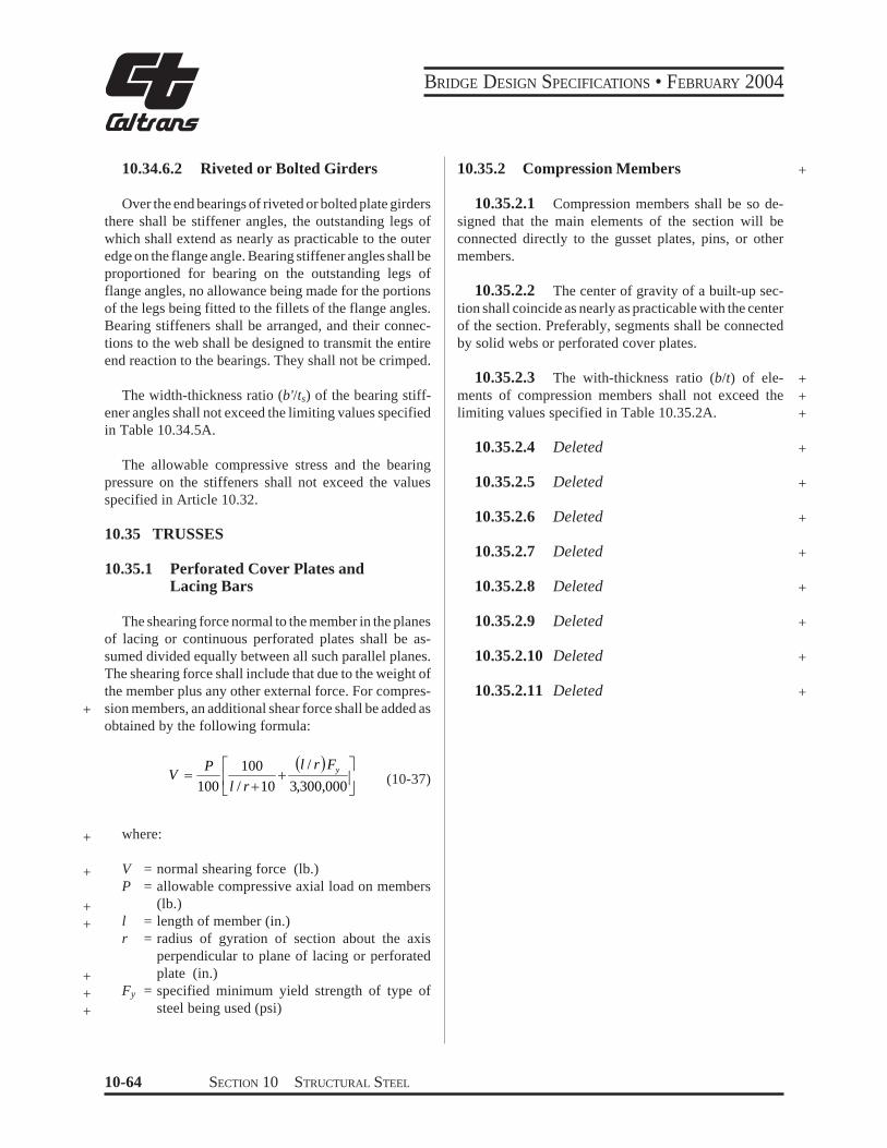
BRIDGE DESIGN SPECIFICATIONS bull FEBRUARY 2004
103462 Riveted or Bolted Girders
Over the end bearings of riveted or bolted plate girders there shall be stiffener angles the outstanding legs of which shall extend as nearly as practicable to the outer edge on the flange angle Bearing stiffener angles shall be proportioned for bearing on the outstanding legs of flange angles no allowance being made for the portions of the legs being fitted to the fillets of the flange angles Bearing stiffeners shall be arranged and their connecshytions to the web shall be designed to transmit the entire end reaction to the bearings They shall not be crimped
The width-thickness ratio (bts) of the bearing stiffshyener angles shall not exceed the limiting values specified in Table 10345A
The allowable compressive stress and the bearing pressure on the stiffeners shall not exceed the values specified in Article 1032
1035 TRUSSES
10351 Perforated Cover Plates and Lacing Bars
+
The shearing force normal to the member in the planes of lacing or continuous perforated plates shall be asshysumed divided equally between all such parallel planes The shearing force shall include that due to the weight of the member plus any other external force For compresshysion members an additional shear force shall be added as obtained by the following formula
V ( )
+
+ =
3300000
10 100
100 yr Fl
rl P
(10-37)
+ where
+
+ +
+ + +
V P
l r
Fy
= normal shearing force (lb) = allowable compressive axial load on members
(lb) = length of member (in) = radius of gyration of section about the axis
perpendicular to plane of lacing or perforated plate (in)
= specified minimum yield strength of type of steel being used (psi)
10352 Compression Members +
103521 Compression members shall be so deshysigned that the main elements of the section will be connected directly to the gusset plates pins or other members
103522 The center of gravity of a built-up secshytion shall coincide as nearly as practicable with the center of the section Preferably segments shall be connected by solid webs or perforated cover plates
103523 The with-thickness ratio (bt) of eleshyments of compression members shall not exceed the limiting values specified in Table 10352A
+ + +
103524 Deleted +
103525 Deleted +
103526 Deleted +
103527 Deleted +
103528 Deleted +
103529 Deleted +
1035210 Deleted +
1035211 Deleted +
10-64 SECTION 10 STRUCTURAL STEEL
BRIDGE DESIGN SPECIFICATIONS bull FEBRUARY 2004
+
+
+
+
+ + + + +
+ + + + + +
+ + + + + +
+ + + + + +
+ + + +
+ + + + +
TABLE 10352A Limiting Width-Thickness Ratios for Compression Member Elements
Description of Component Limiting (bt) When f a
= 044 F y
F y(psi)
Limiting bt
Plates supported on one side outstanding legs of angles and perforated platesndashfor outstanding plates outstanding legs of angles and perforated plates at the perforations (10-38)
le for secondary member16
12 for main members1625
af
36000 50000 70000 90000 100000
12 11 9 8
75
Plates supported on two edges or webs of main component segments ndashfor members of box shape consisting of main plates rolled sections or made up component segments with cover plates
(10-39)454000
le af
36000 50000 70000 90000 100000
32 27 23 20 19
Solid cover plates supported on two edges or webs connecting main members or segmentsndashfor members of H or box shapes consisting of solid cover plates or solid webs connecting main plates or segments
(10-40)505000
le af
36000 50000 70000 90000 100000
40 34 28 25 24
Perforated cover plates supported on two edgesndashfor members of box shapes consisting of perforated cover plates connecting main plates or segments perforated cover plates supported on one side
(10-41)556000
le af
36000 50000 70000 90000 100000
48 41 34 30 29
b = distance between points of support (in) fa = calculated compressive stress in the component under consideration (psi) Fy = specified minimum yield strength of the component under consideration (psi) t = component plate thickness (in)
Note The point of support shall be the inner line of fasteners or fillet welds connecting the plate to the main segment For plates butt welded to the flange edge of rolled segments the point of support may be taken as the weld whenever the ratio of outstanding flange width to flange thickness of the rolled segment is less than seven Otherwise point of support shall be the root of flange of rolled segment Terminations of the butt welds are to be ground smooth
SECTION 10 STRUCTURAL STEEL 10-65
BRIDGE DESIGN SPECIFICATIONS bull FEBRUARY 2004
1036 COMBINED STRESSES
All members subjected to both axial compression and + flexure shall be proportioned to satisfy the following
requirements
fa +Fa
and
fa
0472 yF
where
+ fa
+ fbx fby
+ + Fa
+ + Fbx Fby
+
+ Fe
+ + E
Kb
+ Lb
rb
+ Cmx Cmy
FS
Cmx fbx Cmy fby+ le 10
f fa a1minus Fbx 1minus Fby
(10-42)F prime prime ex Fey
f fbx by+ + le 10 (at points of support)F Fbx by
(10-43)
π 2 EFe prime = )2 (10-44)FS(K L rb b b
= calculated axial stress (psi) = calculated compressive bending stress
about the x axis and y axis respectively (psi)
= allowable axial if axial force alone exists regardless of the plane of bending (psi)
= allowable compressive bending stress if bending moment alone exists about the x axis and the y axis respectively as evalushyated according to Table 10321A (psi)
= Euler buckling stress divided by a factor of safety (psi)
= modulus of elasticity of steel (psi) = effective length factor in the plane of
bending (see Appendix C) = actual unbraced length in the plane of
bending (in) = radius of gyration in the plane of bending
(in) = coefficient about the x axis and y axis
respectively whose value is taken from Table 1036A
= factor of safety = 212
10-66 SECTION 10 STRUCTURAL STEEL
BRIDGE DESIGN SPECIFICATIONS bull FEBRUARY 2004
+
+ +
+ +
TABLE 1036A Bending-Compression Interaction Coeffcients
Loading Conditions Remarks Cm
Computed moments maximum at end joint translation 085p p not prevented
r
Computed moments maximum at end no transverseloading joint translation prevented
( )
+ 0604
2
1
M M
r p
p
Transverse loading joint translation prevented 085r
p
p
p pTransverse loading joint translation prevented 10
r
M1 = smaller end moment M1M2 is positive when member is bent in single curvature M1M2 is negative when member is bent in reverse curvature In all cases Cm may be conservatively taken equal to 10
1037 SOLID RIB ARCHES
2
2
=
r KL
EFe
π
(10-46)
10371 Moment Amplification and Allowable Stress
103711 The calculated compressive bending stress due to live load plus impact loading that are determined by an analysis which neglects arch rib deflecshytion shall be increased by an amplification factor AF
e
F
A F TA
171
1
minus =
(10-45)
L = one half of the length of the arch rib (in) A = area of cross section (in2) r = radius of gyration (in) K = effective length factor of the arch rib
K Values for Use in Calculating Fe and Fa
Rise to Span 3-Hinged 2-Hinged Fixed Ratio Arch Arch Arch
01 - 02 116 104 070
where
T = arch rib thrust at the quarter point from dead plus live plus impact loading (lb)
Fe = Euler buckling stress (psi)
02 - 03 113 110 070
03 - 04 116 116 072
+
+
+
SECTION 10 STRUCTURAL STEEL 10-67
BRIDGE DESIGN SPECIFICATIONS bull FEBRUARY 2004
103712 The arch rib shall be proportioned to 103723 If two longitudinal stiffeners are used at satisfy the following requirement the one-third points of the web depth D the moment of
inertia of each stiffener shall meet the following require- + fa
Fa
+ ment +fb le 10 (10-47)Fb
I s ge 22Dtw 3 (10-53) +
where
+ fa = the calculated axial stress (psi) + fb = the calculated bending stress including moshy+ ment amplification at the extreme fiber (psi) + Fa = the allowable axial stress (psi) + Fb = the allowable bending stress (psi)
103713 For buckling in the vertical plane
103724 The width-thickness ratio (bts) of any outstanding element of the web stiffeners shall not exshyceed the limiting values specified in Table 10372A +
103725 Deleted +
10373 Flange Plates
The width-thickness ratio (btf) of flange plates shall not + +exceed the limiting values specified in Table 10372A
2
Fy
K L
2π
Fa = Fy
FS103731 Deleted +
103732 Deleted +
r1minus4 E (10-48)
+ where KL as defined above and FS is factor of safety = + 212
103714 The effects of lateral slenderness should be investigated Tied arch ribs with the tie and roadway suspended from the rib are not subject to moment amplishyfication and Fa shall be based on an effective length equal to the distance along the arch axis between susshypenders for buckling in the vertical plane However the smaller cross-sectional area of cable suspenders may result in an effective length slightly longer than the distance between suspenders
10372 Web Plates
+ 103721 The width-thickness ratio (Dtw) of the + web plates shall not exceed the limiting values specified + in Table 10372A
103722 If one longitudinal stiffener is used at mid-depth of the web the moment of inertia of the stiffener about an axis parallel to the web and at the base
+ of the stiffener shall meet the following requirement
+ I s ge 075Dtw 3 (10-51)
10-68 SECTION 10 STRUCTURAL STEEL
BRIDGE DESIGN SPECIFICATIONS bull FEBRUARY 2004
TABLE 10372A Limiting Width-Thickness Ratios for Solid Rib Arches +
Web Plates
Flange Plates
b = fa = fb = tf = ts = tw =
Description of Component
Without longitudinal stiffiners
With one longitudinal stiffener at the one-third point of the web depth
With two longitudinal stiffeners at the one-third point of the web design
Outstanding element of stiffiners
Web plate equations apply between limits
Plates between webs
Overhang plates
Width +Thickness Limiting Width-Thickness Ratio
Ratio
5000 +pound 60 (10-49)fa
7500 pound 90 (10-50) +D t w fa
10000 pound 120 (10-52) +fa
1625 pound 12 (10-54)b tcent +s fa + fb 3
fb02 pound pound 07 +(10-55)fa + fb 3
4250 pound 47 (10-56) +
fa + fb
centb t f 1625 (10-57)
fa + fb
pound 12 +
width of flange plate or width of outstanding element of web stiffeners (in) + calculated axial compressive stress in the component under consideration (psi) + calculated compressive bending stress in the component under consideration (psi) + flange plate thickness (in) + web stiffener outstanding element thickness (in) + web plate thickness (in) +
SECTION 10 STRUCTURAL STEEL 10-69
BRIDGE DESIGN SPECIFICATIONS bull FEBRUARY 2004
+ 1038 COMPOSITE BEAMS AND GIRDERS +
10381 General
+ 103811 This section pertains to structures comshy
posed of steel beams or girders with concrete slabs connected by shear connectors
103812 General specifications pertaining to the design of concrete and steel structures shall apply to strucshytures utilizing composite girders where such specifications are applicable Composite girders and slabs shall be deshysigned and the stresses computed by the composite moment of inertia method and shall be consistent with the predetershymined properties of the various materials used
+ 103813 The ratio of the modulus of elasticity of steel (29000000 psi) to those of normal weight concrete (W = 145 pcf) of various design strengths shall be as follows
+
+
+
f c
n
f c
= specified compressive strength of concrete as determined by cylinder tests at the age of 28 days (psi)
= ratio of modulus of elasticity of steel to that of concrete The value of n as a function of the specified compressive strength of concrete shall be assumed as follows
= 2000 - 2300 n = 11 2400 - 2800 n = 10 2900 - 3500 n = 9 3600 - 4500 n = 8 4600 - 5900 n = 7 6000 or more n = 6
+ +
+
103814 The effect of creep shall be considered in the design of composite girders which have dead loads acting on the composite section In such structures bendshying stresses and horizontal shears produced by dead loads acting on the composite section shall be computed for n as given above or for this value multiplied by 3 whichshyever gives the higher bending stresses and shears
103815 If concrete with expansive characterisshytics is used composite design should be used with caushytion and provision must be made in the design to accomshymodate the expansion
103816 Composite sections in simple spans and the positive moment regions of continuous spans should
preferably be proportioned so that the neutral axis lies below the top surface of the steel beam Concrete on the tension side of the neutral axis shall not be considered in calculating resisting moments In the negative moment regions of continuous spans only the slab reinforcement can be considered to act compositely with the steel beams in calculating resisting moments Mechanical anchorshyages shall be provided in the composite regions to deshyvelop stresses on the plane joining the concrete and the steel Concrete on the tension side of the neutral axis may be considered in computing moments of inertia for deshyflection calculations for determining stiffness used in + calculating moments and shears and for computing fashytigue stress ranges and fatigue shear ranges as permitted under the provisions of Article1031and 103851
103817 The steel beams or girders especially if not supported by intermediate falsework shall be invesshytigated for stability and strength for the loading applied during the time the concrete is in place and before it has hardened The casting or placing sequence specified in the plans for the composite concrete deck shall be considshyered when calculating the moments and shears on the steel section The maximum flange compression stress shall not exceed the value specified in Table 10321A for partially supported or unsupported compression flanges multiplied by a factor of 14 but not exceed 055Fy The sum of the non-composite and composite dead-load shear stresses in the web shall not exceed the shear-buckling capacity of the web multiplied by a factor of 135 nor the allowable shear stress as follows
Fv = 045CFy le 033Fy (10-57a)
where
+C = constant specified in Article 103442
10382 Shear Connectors
103821 The mechanical means used at the juncshytion of the girder and slab for the purpose of developing the shear resistance necessary to produce composite action shall conform to the specifications of the respecshytive materials The shear connectors shall be of types that + permit a thorough compaction of the concrete in order to ensure that their entire surfaces are in contact with the concrete They shall be capable of resisting both horizonshytal and vertical movement between the concrete and the steel
10-70 SECTION 10 STRUCTURAL STEEL
BRIDGE DESIGN SPECIFICATIONS bull FEBRUARY 2004
103822 The capacity of stud and channel shear connectors welded to the girders is given in Article 10385 Channel shear connectors shall have at least 316-inch fillet welds placed along the heel and toe of the channel
103823 The clear depth of concrete cover over the tops of the shear connectors shall be not less than 2 inches Shear connectors shall penetrate at least 2 inches above bottom of slab
103824 The clear distance between the edge of a girder flange and the edge of the shear connectors shall be not less than 1 inch Adjacent stud shear connectors shall not be closer than 4 diameters center to center
10383 Effective Flange Width
103831 In composite girder construction the asshysumed effective width of the slab as a T-beam flange shall not exceed the following
(1) One-fourth of the span length of the girder (2) The distance center to center of girders (3) Twelve times the least thickness of the slab
103832 For girders having a flange on one side only the effective flange width shall not exceed oneshytwelfth of the span length of the girder or six times the thickness of the slab or one-half the distance center to center of the next girder
10384 Stresses
103841 Maximum compressive and tensile stresses in girders that are not provided with temporary supports during the placing of the permanent dead load shall be the sum of the stresses produced by the dead loads acting on the steel girders alone and the stresses produced by the superimshyposed loads acting on the composite girder When girders are provided with effective intermediate supports that are kept in place until the concrete has attained 75 percent of its required 28-day strength the dead and live load stresses shall be computed on the basis of the composite section
103842 A continuous composite bridge may be built with shear connectors either in the positive moment regions or throughout the length of the bridge The positive moment regions may be designed with composshyite sections as in simple spans Shear connectors shall be
provided in the negative moment portion in which the reinforcement steel embedded in the concrete is considshyered a part of the composite section In case the reinforceshyment steel embedded in the concrete is not used in computing section properties for negative moments shear connectors need not be provided in these portions of the spans but additional anchorage connectors shall be placed in the region of the point of dead load contra-flexure in accordance with Article 1038513 Shear connectors shall be provided in accordance with Article 10385
103843 The minimum longitudinal reinforceshyment including the longitudinal distribution reinforceshyment must equal or exceed one percent of the crossshysectional area of the concrete slab whenever the longitushydinal tensile stress in the concrete slab due to either the construction loads or the design loads exceeds f specifiedt in Article 815211 The area of the concrete slab shall be equal to the structural thickness times the entire width of the bridge deck The required reinforcement shall be No 6 bars or smaller spaced at not more than 12 inches Two-thirds of this required reinforcement is to be placed in the top layer of slab Placement of distribution steel as specified in Article 32410 is waived
103844 When shear connectors are omitted from the negative moment region the longitudinal reinforceshyment shall be extended into the positive moment region beyond the anchorage connectors at least 40 times the reinforcement diameter For epoxy-coated bars the length to be extended into the positive moment region beyond the anchorage connectors should be modified to comply with Article 82523
10385 Shear
103851 Horizontal Shear
The maximum pitch of shear connectors shall not exceed 24 inches except over the interior supports of continuous beams where wider spacing may be used to avoid placing connectors at locations of high stresses in the tension flange
Resistance to horizontal shear shall be provided by meshychanical shear connectors at the junction of the concrete slab and the steel girder The shear connectors shall be mechanical devices placed transversely across the flange
SECTION 10 STRUCTURAL STEEL 10-71
BRIDGE DESIGN SPECIFICATIONS bull FEBRUARY 2004
of the girder spaced at regular or variable intervals The shear connectors shall be designed for fatigue and
+ checked for design strength
1038511 Fatigue
The range of horizontal shear shall be computed by the formula
VrQSr = (10-58)I
where
+ Sr = range of horizontal shear (lbin) at the junction of the slab and girder at the point in the span under consideration
+ Vr = range of shear due to live loads and impact (lb) at any section the range of shear shall be taken as the difference in the minimum and maximum shear envelopes (excluding dead loads)
Q = statical moment about the neutral axis of the composite section of the transformed concrete
+ area (in3) Between points of dead-load contraflexure the static moment about the neushytral axis of the composite section of the area of reinforcement embedded in the concrete may be used unless the transformed concrete area is considered to be fully effective for the negative moment in computing the longitudinal ranges of stress
+ I = moment of inertia of the transformed short-term + composite section (in4) Between points of deadshy
load contraflexure the moment of inertia of the steel girder including the area of reinforcement embedded in the concrete may be used unless the transformed concrete area is considered to be fully effective for the negative moment in
+ computing the longitudinal ranges of stress
+ (In the formula the concrete area is transformed into an equivalent area of steel by dividing the effective concrete flange width by the modular ratio n)
Reference is made to the paper titled ldquoFatigue Strength of Shear Connectorsrdquo by Roger G Slutter and John W Fisher in Highway Research Record No 147 published by the Highway Research Board Washington DC 1966
The allowable range of horizontal shear Zr (lb) on an + individual connector is as follows
Channels
Zr = Bw (10-59)
Welded studs (for Hd ge 4)
Zr = α d2 (10-60)
where
w = length of a channel shear connector (in) mea- + sured in a transverse direction on the flange of a girder
d = diameter of stud (in) + α = 13000 for 100000 cycles +
10600 for 500000 cycles 7850 for 2000000 cycles 5500 for over 2000000 cycles
B = 4000 for 100000 cycles 3000 for 500000 cycles 2400 for 2000000 cycles 2100 for over 2000000 cycles
H = height of stud (in) +
The required pitch of shear connectors is determined by dividing the allowable range of horizontal shear of all connectors at one transverse girder cross-section (ΣZr) by the horizontal range of shear Sr but not to exceed the maximum pitch specified in Article 103851 Over the interior supports of continuous beams the pitch may be modified to avoid placing the connectors at locations of high stresses in the tension flange provided that the total number of connectors remains unchanged
1038512 Design Strength +
The number of connectors so provided for fatigue shall be checked to ensure that adequate connectors are provided for design strength +
10-72 SECTION 10 STRUCTURAL STEEL
BRIDGE DESIGN SPECIFICATIONS bull FEBRUARY 2004
+ The number of shear connectors required shall meet + the following requirement
PN1 Dagger (10-61)f Su
where
N1 = number of connectors between points of maxishymum positive moment and adjacent end supports
+ Su = design strength of the shear connector as given + below (lb)
f = reduction factor = 085 + P = horizontal shear force transferred by shear conshy+ nectors as defined hereafter as P1 or P2
At points of maximum positive moment the force in the slab is taken as the smaller value of the formulas
P1 = AsFy (10-62)
or
P = 085 f centbt (10-63)2 c s
where
As = total area of the steel section including cover shy+ plates (in2) + Fy = specified minimum yield strength of the steel + being used (psi) + fc
cent = specified compressive strength of concrete at + age of 28 days (psi) + b = effective flange width given in Article 10383 (in) + ts = thickness of the concrete slab (in)
The number of connectors N2 required between the points of maximum positive moment and points of adjashy
+ cent maximum negative moment shall meet the followshy+ ing requirement
P + PN Dagger 3
2 (10-64)f Su
At points of maximum negative moment the force in the slab is taken as
r rP3 = As Fy (10-65)
where
Asr = total area of longitudinal reinforcing steel at
the interior support within the effective flange width (in2) +
F r y = specified minimum yield strength of the rein- +
forcing steel (psi) +
The design strength of the shear connector is given + as follows Channels
[ t ) centSu = 550 h+ W fc (10-66)Ł 2 ł
Welded studs (for Hd gt 4)
S = 04 d 2 f c E pound 60000A (10-67)u c sc
where
Ec = modulus of elasticity of the concrete (psi) + Ec = w
3 233 f ccent (10-68)
Su = design strength of individual shear connector + (lb) +
h = average flange thickness of the channel flange (in) +
t = thickness of the web of a channel (in) + W = length of a channel shear connector (in) + fc cent = specified compressive strength of the concrete
at 28 days (psi) + d = diameter of stud (in) + w = unit weight of concrete (pcf) + Asc = area of welded stud cross section (in2) +
SECTION 10 STRUCTURAL STEEL 10-73
BRIDGE DESIGN SPECIFICATIONS bull FEBRUARY 2004
1038513 Additional Connectors to Develop Slab Stresses
The number of additional connectors required at points of contraflexure when reinforcing steel embedded in the concrete is not used in computing section propershyties for negative moments shall be computed by the formula
cN = r
r s r
Z A f
(10-69)
where
Nc = number of additional connectors for each beam at point of contraflexure
+ s rA = total area of longitudinal slab reinforcing steel
for each beam over interior support (in2) + fr = range of stress due to live load plus impact in
the slab reinforcement over the support (psi) (in lieu of more accurate computations fr may be taken as equal to 10000 psi)
+ Zr = allowable range of horizontal shear on an individual shear connector (lb)
The additional connectorsNc shall be placed adjacent to the point of dead load contraflexure within a distance equal to one-third the effective slab width ie placed either side of this point or centered about it It is prefershyable to locate field splices so that they clear the connecshytors
+ 103852 Vertical Shear
The intensity of shearing stress in a composite girder may be determined on the basis that the web of the steel girder carries the total external shear neglecting the effects of the steel flanges and of the concrete slab The shear may be assumed to be uniformly distributed throughout the gross area of the web
10386 Deflection
103861 The provisions of Article 106 in regard to deflections from live load plus impact also shall be applicable to composite girders
103862 When the girders are not provided with falsework or other effective intermediate support during
the placing of the concrete slab the deflection due to the weight of the slab and other permanent dead loads added before the concrete has attained 75 percent of its required 28-day strength shall be computed on the basis of noncomposite action
1039 COMPOSITE BOX GIRDERS
10391 General
103911 This section pertains to the design of simple and continuous bridges of moderate length supshyported by two or more single cell composite box girders The distance center-to-center of flanges of each box should be the same and the average distance center-toshycenter of flanges of adjacent boxes shall be not greater than 12 times and not less than 08 times the distance center-to-center of flanges of each box In addition to the above when nonparallel girders are used the distance center-to-center of adjacent flanges at supports shall be no greater than 135 times and not less than 065 times the distance center-to-center of flanges of each box The cantilever overhang of the deck slab including curbs and parapets shall be limited to 60 percent of the average distance center-to-center of flanges of adjacent boxes but shall in no case exceed 6 feet +
103912 The provisions of these Specifications shall govern where applicable except as specifically modified by Articles 10391 through 10398
10392 Lateral Distribution of Loads for Bending Moment
103921 The live load bending moment for each box girder shall be determined by applying to the girder the fraction WL of a wheel load (both front and rear) determined by the following equation
085WL = 01 + 17 R + (10-70)Nw
where
N wR = (10-71)Numberof Box Girders
10-74 SECTION 10 STRUCTURAL STEEL
BRIDGE DESIGN SPECIFICATIONS bull FEBRUARY 2004
Nw = Wc12 reduced to the nearest whole number + Wc = roadway width between curbs (ft) or barriers
if curbs are not used
+ R shall not be less than 05 or greater than 15
103922 The provision of Article 312 Reducshytion of Load Intensity shall not apply in the design of box girders when using the design load WL given by the above equation
+ 10393 Web Plates
103931 Vertical Shear
The design shear Vw for a web shall be calculated using the following equation
VvVw =
10394 Bottom Flange Plates +
103941 General +
The tension flange and the compression flange shall + be considered completely effective in resisting bending if + its width does not exceed one-fifth the span length If the + flange plate width exceeds one-fifth of the span an + amount equal to one-fifth of the span only shall be + considered effective Effective flange plate width shall + be used to calculate the flange bending stress Full flange + plate width shall be used to calculate the allowable + compressive bending stress
1039412 Deleted +
103942 Compression Flanges Unstiffened
1039421 For unstiffened compression flanges + (10-72) the calculated bending stress shall not exceed the allow- +cosθ
able bending stress Fb (psi) determined by either of the + following equations +
where
b
t F
6140 +le+ Vv = vertical shear (lb) for
θ = angle of inclination of the web plate to the vertical
y
Fb = 055 Fy (10-73) + 103932 Secondary Bending Stresses
+
yy Ft b
F
6140 13300lelt1039321 Web plates may be plumb (90deg to botshy for
tom of flange) or inclined If the inclination of the web plates to a plane normal to bottom flange is no greater than 1 to 4 and the width of the bottom flange is no greater than 20 percent of the span the transverse bendshy b Fy
t
minus13300
2 7160
ing stresses resulting from distortion of the span and the transverse bending stresses resulting from distortion of
πFb 055Fy 0224 Fyminus minussin= + the girder cross section and from vibrations of the bottom plate need not be considered For structures in this catshyegory transverse bending stresses due to supplementary
1
(10-74)loadings such as utilities shall not exceed 5000 psi
b 13300 +ge
t Ffor1039322 For structures exceeding these limits a y
detailed evaluation of the transverse bending stresses due to all causes shall be made These stresses shall be limited
2to a maximum stress or range of stress of 20000 psi
t times106 (10-75) +Fb = 576
b
SECTION 10 STRUCTURAL STEEL 10-75
BRIDGE DESIGN SPECIFICATIONS bull FEBRUARY 2004
where+
+ b = flange width between webs (in) + t = flange thickness (in)
1039422 Deleted+
1039423 Deleted+
1039424 The bt ratio preferably should not exshyceed 60 except in areas of low stress near points of dead load contraflexure
+ 1039425 If the bt ratio exceeds 45 longitudinal + stiffeners may be considered
+ 1039426 Deleted
103943 Compression Flanges Stiffened Longitudinally
1039431 Longitudinal stiffeners shall be at equal spacings across the flange width and shall be proporshytioned so that the moment of inertia of each stiffener about an axis parallel to the flange and at the base of the
+ stiffener Is (in4) shall meet the following requirement
+ I s ge φ t3 f w (10-76)
where
φ = 007 k3n4 for values of n greater than 1 + φ = 0125 k3 for a value of n = 1
tf = thickness of the flange (in) w = width of flange between longitudinal stiffeners
+ or distance from a web to the nearest longitudishynal stiffener (in)
n = number of longitudinal stiffeners k = buckling coefficient which shall not exceed 4
+ 1039432 For the longitudinally stiffened flange + including stiffeners the calculated bending stress shall + not exceed the allowable bending stress Fb (psi) detershy+ mined by either of the following equations
w 3070 kle+ for t Fy
In solving these equations a value of k between 2 and 4 generally should be assumed
F = 055 Fb y
3070 k w for Fy
lt le smaller of 60 or t
w
Fb = 055Fy
minus0224 Fy 1minussin
6650 k minus
2 3580 π
k t
y
+
(10-78)
for 6650
Fy
k le
t w le 60
+
Fb t
2 6= 144 k times10 (10-79) +
+1039433 Deleted
+1039434 Deleted
1039435 When longitudinal stiffeners are used it is preferable to have at least one transverse stiffener placed near the point of dead load contraflexure The stiffener should have a size equal to that of a longitudinal stiffener
1039436 If the longitudinal stiffeners are placed at their maximum wt ratio to be designed for the basic allowable design stresses of 055Fy and the number of longitudinal stiffeners exceeds 2 then transverse stiffenshyers should be considered
1039437 Deleted +
(10-77) +
6650 k + F y
w F
10-76 SECTION 10 STRUCTURAL STEEL
0
BRIDGE DESIGN SPECIFICATIONS bull FEBRUARY 2004
100
90
80
70
60
50
Is bt
40
0
0
10
0
k = 4 k = 4 k = 4
=
4
Ffr = Fy
Ffr = 096 Fy
NO STbtbb = 055 Fy
bbb = 05 Fy
IFFENERS REQUIRED
Fy = 6140
Fy = 0800
=
4
=4
Ffr = 085 Fy
t btbb = 047 Fy Fy = 10060
Note Ffr refebb refersFy is in
rs to Load Factor to Working Stres
1bin
Design s Design
=
k = 56
=
k = 56 k
=
= 56
b b =
05
5 F y
F fr =
Fy
b b =
05
F y
fr =
09
6 F y
F y y
WITHOUT TRANSVERSE STIFFENERS
F
b b =
047
F f
r = 0
85 F
k = 4 k = 4 k = 4
k = 5
= k = 5
=
=
k = 5 WITSH TRANSVERSE TIFFENERS
k
= 1
k = 4= 178
k = 4 = 1
= 1
k = 178
k = 4
k = 178
= = = =
Is = 67bt Is = 00bt 4 Is = 160bt 5 Is = 1bt
5000 10000 15000 0000 5000 0000 5000 40000
b Fyt
FIGURE 103943A Longitudinal StiffenersntildeBox Girder Compression Flange
SECTION 10 STRUCTURAL STEEL 10-77
BRIDGE DESIGN SPECIFICATIONS bull FEBRUARY 2004
3
2 5
2
a b
1 5
1
0 5
0
( fs 0 47 Fy) (Fs 0 85 Fy)
b t
Fy
Is for longitudinal stiffeners 8 t3w (in 4)
k1 4 k1 2 25
k1 2 25k1 4
k1 2 5 k1 4
k1 1 78
k1 1 78
k1 2 78k1 4
2
5
5
4
4
4
3
3
3
2
2
2
3
3
4
3
4 4
5 5 k1 4k1 2 78
k1 2 5
k1 4
k1 2
2
2
Note fs refers to Working Stress Design Fs refers to Load Factor Design Fy is in lbin 2
a b
( fs 0 47 Fy) (Fs 0 85 Fy)
a b
( fs 0 55 Fy) (Fs Fy)
a b ( fs 0 53 Fy) (Fs 0 9 Fy)
It b f Fy
It b f Fy
( fs 0 53 Fy) (Fs 0 9 Fy)
It b f Fy
( fs 0 55 Fy) (Fs Fy)
k1 4
0 09
0 08
0 07
0 0
0 05
0 04
It b f Fy
0 03
0 02
0 01
10000 15000 20000 25000 30000 35000 40000 45000
FIGURE 103943B Spacing and Size of Transverse Stiffeners (for Flange Stiffened Longitudinally and Transversely)
10-78 SECTION 10 STRUCTURAL STEEL
0
BRIDGE DESIGN SPECIFICATIONS bull FEBRUARY 2004
103944 Compression Flanges Stiffened Longitudinally and Transversely
1039441 The longitudinal stiffeners shall be at equal spacings across the flange width and shall be proportioned so that the moment of inertia of each stiffshyeners about an axis parallel to the flange and at the base
+ of the stiffeners meet the following requirement
I s ge 8t3 f w (10-80)
1039442 The transverse stiffeners shall be proshyportioned so that the moment of inertia of each stiffener about an axis through the centroid of the section and parallel
+ to its bottom edge meets the following requirement
3 3 fs Af+ It ge 010 (n + 1) w (10-81)E do
where
Af = area of bottom flange including longitudinal + stiffeners (in2) + do = spacing of transverse stiffeners (in)
fs = maximum longitudinal bending stress in the flange of the panels on either side of the transshy
+ verse stiffeners (psi) + E = modulus of elasticity of steel (psi)
+ 1039443 For the flange including stiffeners the + calculated bending stress shall not exceed the allowable + bending stress Fb (psi) determined by either of the + following equations
w 3070 k1+ lefor t Fy
+ Fb = 055 Fy (10-82)
3070 k1 w 6650 k1 le or + lt smaller of 60for Fy t F y
w F 6650 k1 minus y
π t F = 055F minus0224 F 1minussinb y y + 2 3580 k1
(10-83)
6650 k1 wle le 60 +for Fy t
t 2
6Fb = 144 k1 times10 (10-84) + w
where
( ) [ ( ) ( ) 1
1 22
2
1 +
+ =
a bn
a bk ]
( ) [ 1 ]011 873
2
++
+
n (10-85) +
1039444 Deleted +
1039445 Deleted +
1039446 The maximum value of the buckling coefficient k1 shall be 4 When k1 has its maximum value the transverse stiffeners shall have a spacing a equal to or less than 4w If the ratio ab exceeds 3 transverse stiffeners are not necessary
1039447 The transverse stiffeners need not be connected to the flange plate but shall be connected to the webs of the box and to each longitudinal stiffener The connection to the web shall be designed to resist the vertical force determined by the formula
R = FySs
w (10-86)2 b
where
Ss = section modulus of the transverse stiffener (in3) +
SECTION 10 STRUCTURAL STEEL 10-79
BRIDGE DESIGN SPECIFICATIONS bull FEBRUARY 2004
1039448 The connection to each longitudinal stiffener shall be designed to resist the vertical force determined by the formula
F S =Rs n
y
bs
(10-87)
103945 Compression Flange Stiffeners General
+ 1039451 The width-thickness ratio (bts) of any outstanding element of the flange stiffeners shall not
+ exceed the limiting values specified in Table 10345A
1039452 Longitudinal stiffeners shall be exshytended to locations where the maximum stress in the flange does not exceed that allowed for base metal adjacent to or connected by fillet welds
+ 10395 Flange to Web Welds
The total effective thickness of the web-flange welds + shall be not less than the thickness of the web Regardless
of the type weld used welds shall be deposited on both sides of the connecting flange or web plate
10396 Diaphragms
103961 Diaphragms cross-frames or other means shall be provided within the box girders at each support to resist transverse rotation displacement and distortion
103962 Intermediate diaphragms or cross-frames are not required for steel box girder bridges designed in accordance with this specification
10397 Lateral Bracing
Generally no lateral bracing system is required beshytween box girders A horizontal wind load of 50 pounds per square foot shall be applied to the area of the supershystructure exposed in elevation Half of the resulting force shall be applied in the plane of the bottom flange The section assumed to resist the horizontal load shall consist of the bottom flange acting as a web and 12 times the thickness of the webs acting as flanges A lateral bracing system shall be provided if the combined stresses due to the specified horizontal force and dead load of steel and deck exceed 150 percent of the allowable design stress
10398 Access and Drainage
Consistent with climate location and materials considshyeration shall be given to the providing of manholes or other openings either in the deck slab or in the steel box for form removal inspection maintenance drainage etc
1040 HYBRID GIRDERS
10401 General
104011 This section pertains to the design of girders that utilize a lower strength steel in the web than in one or both of the flanges It applies to composite and noncomposite plate girders and composite box girders At any cross section where the bending stress in either flange exceeds 55 percent of minimum specified yield strength of the web steel the compression-flange area shall not be less than the tension-flange area The top-flange area shall include the transformed area of any portion of the slab or reinforcing steel that is considered to act compositely with the steel girder
104012 The provisions of these Specifications shall govern where applicable except as specifically modified by Articles 10401 through 10404
+
10402 Allowable Stresses
104021 Bending
1040211 The bending stress in the web may exceed the allowable stress for the web steel provided that the stress in each flange does not exceed the allowshyable stress from Articles 103 or 1032 for the steel in that flange multiplied by the reduction factor R
( ) ( ) ( ψ )βψ
ψαψαβψ minus+
+minusminusminus=
36 31
1 2
R (10-89)
(See Figures 104021A and 104021B)
where
α = specified minimum yield strength of the web divided by the specified minimum yield strength of the tension flange
β = area of the web divided by the area of the tension flange
Bottom flange of orthotropic deck bridge
+
10-80 SECTION 10 STRUCTURAL STEEL
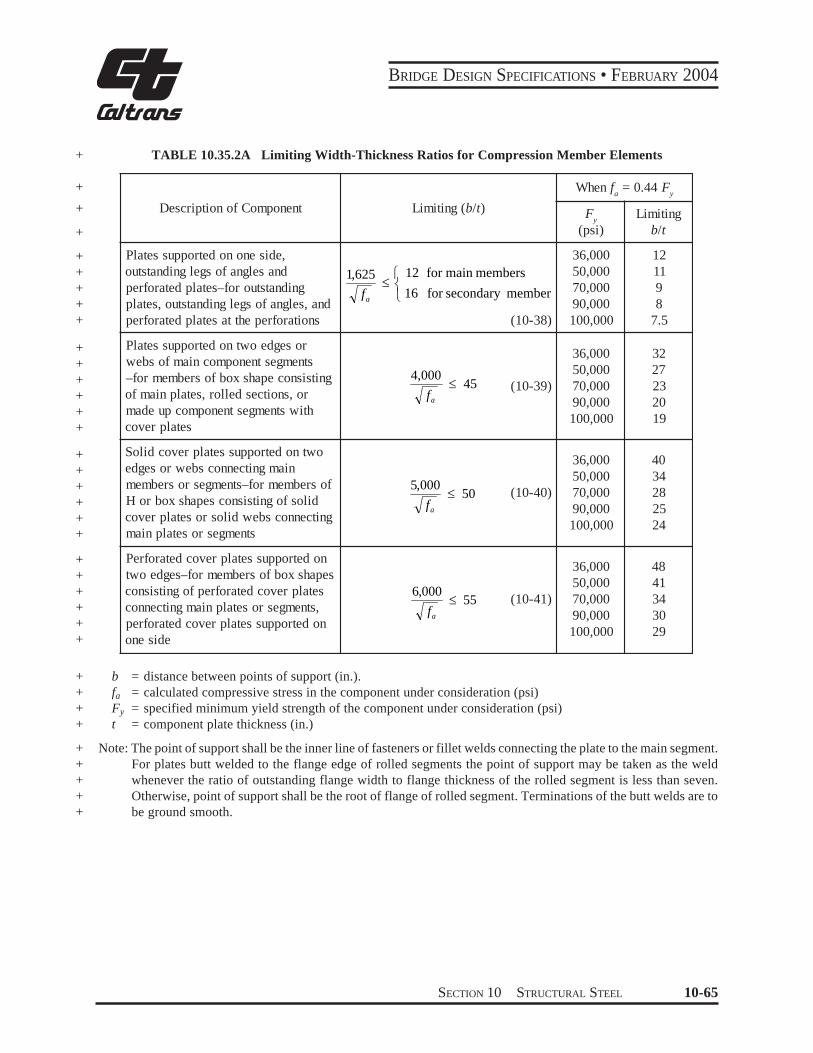
BRIDGE DESIGN SPECIFICATIONS bull FEBRUARY 2004
+
+
+
+
+ + + + +
+ + + + + +
+ + + + + +
+ + + + + +
+ + + +
+ + + + +
TABLE 10352A Limiting Width-Thickness Ratios for Compression Member Elements
Description of Component Limiting (bt) When f a
= 044 F y
F y(psi)
Limiting bt
Plates supported on one side outstanding legs of angles and perforated platesndashfor outstanding plates outstanding legs of angles and perforated plates at the perforations (10-38)
le for secondary member16
12 for main members1625
af
36000 50000 70000 90000 100000
12 11 9 8
75
Plates supported on two edges or webs of main component segments ndashfor members of box shape consisting of main plates rolled sections or made up component segments with cover plates
(10-39)454000
le af
36000 50000 70000 90000 100000
32 27 23 20 19
Solid cover plates supported on two edges or webs connecting main members or segmentsndashfor members of H or box shapes consisting of solid cover plates or solid webs connecting main plates or segments
(10-40)505000
le af
36000 50000 70000 90000 100000
40 34 28 25 24
Perforated cover plates supported on two edgesndashfor members of box shapes consisting of perforated cover plates connecting main plates or segments perforated cover plates supported on one side
(10-41)556000
le af
36000 50000 70000 90000 100000
48 41 34 30 29
b = distance between points of support (in) fa = calculated compressive stress in the component under consideration (psi) Fy = specified minimum yield strength of the component under consideration (psi) t = component plate thickness (in)
Note The point of support shall be the inner line of fasteners or fillet welds connecting the plate to the main segment For plates butt welded to the flange edge of rolled segments the point of support may be taken as the weld whenever the ratio of outstanding flange width to flange thickness of the rolled segment is less than seven Otherwise point of support shall be the root of flange of rolled segment Terminations of the butt welds are to be ground smooth
SECTION 10 STRUCTURAL STEEL 10-65
BRIDGE DESIGN SPECIFICATIONS bull FEBRUARY 2004
1036 COMBINED STRESSES
All members subjected to both axial compression and + flexure shall be proportioned to satisfy the following
requirements
fa +Fa
and
fa
0472 yF
where
+ fa
+ fbx fby
+ + Fa
+ + Fbx Fby
+
+ Fe
+ + E
Kb
+ Lb
rb
+ Cmx Cmy
FS
Cmx fbx Cmy fby+ le 10
f fa a1minus Fbx 1minus Fby
(10-42)F prime prime ex Fey
f fbx by+ + le 10 (at points of support)F Fbx by
(10-43)
π 2 EFe prime = )2 (10-44)FS(K L rb b b
= calculated axial stress (psi) = calculated compressive bending stress
about the x axis and y axis respectively (psi)
= allowable axial if axial force alone exists regardless of the plane of bending (psi)
= allowable compressive bending stress if bending moment alone exists about the x axis and the y axis respectively as evalushyated according to Table 10321A (psi)
= Euler buckling stress divided by a factor of safety (psi)
= modulus of elasticity of steel (psi) = effective length factor in the plane of
bending (see Appendix C) = actual unbraced length in the plane of
bending (in) = radius of gyration in the plane of bending
(in) = coefficient about the x axis and y axis
respectively whose value is taken from Table 1036A
= factor of safety = 212
10-66 SECTION 10 STRUCTURAL STEEL
BRIDGE DESIGN SPECIFICATIONS bull FEBRUARY 2004
+
+ +
+ +
TABLE 1036A Bending-Compression Interaction Coeffcients
Loading Conditions Remarks Cm
Computed moments maximum at end joint translation 085p p not prevented
r
Computed moments maximum at end no transverseloading joint translation prevented
( )
+ 0604
2
1
M M
r p
p
Transverse loading joint translation prevented 085r
p
p
p pTransverse loading joint translation prevented 10
r
M1 = smaller end moment M1M2 is positive when member is bent in single curvature M1M2 is negative when member is bent in reverse curvature In all cases Cm may be conservatively taken equal to 10
1037 SOLID RIB ARCHES
2
2
=
r KL
EFe
π
(10-46)
10371 Moment Amplification and Allowable Stress
103711 The calculated compressive bending stress due to live load plus impact loading that are determined by an analysis which neglects arch rib deflecshytion shall be increased by an amplification factor AF
e
F
A F TA
171
1
minus =
(10-45)
L = one half of the length of the arch rib (in) A = area of cross section (in2) r = radius of gyration (in) K = effective length factor of the arch rib
K Values for Use in Calculating Fe and Fa
Rise to Span 3-Hinged 2-Hinged Fixed Ratio Arch Arch Arch
01 - 02 116 104 070
where
T = arch rib thrust at the quarter point from dead plus live plus impact loading (lb)
Fe = Euler buckling stress (psi)
02 - 03 113 110 070
03 - 04 116 116 072
+
+
+
SECTION 10 STRUCTURAL STEEL 10-67
BRIDGE DESIGN SPECIFICATIONS bull FEBRUARY 2004
103712 The arch rib shall be proportioned to 103723 If two longitudinal stiffeners are used at satisfy the following requirement the one-third points of the web depth D the moment of
inertia of each stiffener shall meet the following require- + fa
Fa
+ ment +fb le 10 (10-47)Fb
I s ge 22Dtw 3 (10-53) +
where
+ fa = the calculated axial stress (psi) + fb = the calculated bending stress including moshy+ ment amplification at the extreme fiber (psi) + Fa = the allowable axial stress (psi) + Fb = the allowable bending stress (psi)
103713 For buckling in the vertical plane
103724 The width-thickness ratio (bts) of any outstanding element of the web stiffeners shall not exshyceed the limiting values specified in Table 10372A +
103725 Deleted +
10373 Flange Plates
The width-thickness ratio (btf) of flange plates shall not + +exceed the limiting values specified in Table 10372A
2
Fy
K L
2π
Fa = Fy
FS103731 Deleted +
103732 Deleted +
r1minus4 E (10-48)
+ where KL as defined above and FS is factor of safety = + 212
103714 The effects of lateral slenderness should be investigated Tied arch ribs with the tie and roadway suspended from the rib are not subject to moment amplishyfication and Fa shall be based on an effective length equal to the distance along the arch axis between susshypenders for buckling in the vertical plane However the smaller cross-sectional area of cable suspenders may result in an effective length slightly longer than the distance between suspenders
10372 Web Plates
+ 103721 The width-thickness ratio (Dtw) of the + web plates shall not exceed the limiting values specified + in Table 10372A
103722 If one longitudinal stiffener is used at mid-depth of the web the moment of inertia of the stiffener about an axis parallel to the web and at the base
+ of the stiffener shall meet the following requirement
+ I s ge 075Dtw 3 (10-51)
10-68 SECTION 10 STRUCTURAL STEEL
BRIDGE DESIGN SPECIFICATIONS bull FEBRUARY 2004
TABLE 10372A Limiting Width-Thickness Ratios for Solid Rib Arches +
Web Plates
Flange Plates
b = fa = fb = tf = ts = tw =
Description of Component
Without longitudinal stiffiners
With one longitudinal stiffener at the one-third point of the web depth
With two longitudinal stiffeners at the one-third point of the web design
Outstanding element of stiffiners
Web plate equations apply between limits
Plates between webs
Overhang plates
Width +Thickness Limiting Width-Thickness Ratio
Ratio
5000 +pound 60 (10-49)fa
7500 pound 90 (10-50) +D t w fa
10000 pound 120 (10-52) +fa
1625 pound 12 (10-54)b tcent +s fa + fb 3
fb02 pound pound 07 +(10-55)fa + fb 3
4250 pound 47 (10-56) +
fa + fb
centb t f 1625 (10-57)
fa + fb
pound 12 +
width of flange plate or width of outstanding element of web stiffeners (in) + calculated axial compressive stress in the component under consideration (psi) + calculated compressive bending stress in the component under consideration (psi) + flange plate thickness (in) + web stiffener outstanding element thickness (in) + web plate thickness (in) +
SECTION 10 STRUCTURAL STEEL 10-69
BRIDGE DESIGN SPECIFICATIONS bull FEBRUARY 2004
+ 1038 COMPOSITE BEAMS AND GIRDERS +
10381 General
+ 103811 This section pertains to structures comshy
posed of steel beams or girders with concrete slabs connected by shear connectors
103812 General specifications pertaining to the design of concrete and steel structures shall apply to strucshytures utilizing composite girders where such specifications are applicable Composite girders and slabs shall be deshysigned and the stresses computed by the composite moment of inertia method and shall be consistent with the predetershymined properties of the various materials used
+ 103813 The ratio of the modulus of elasticity of steel (29000000 psi) to those of normal weight concrete (W = 145 pcf) of various design strengths shall be as follows
+
+
+
f c
n
f c
= specified compressive strength of concrete as determined by cylinder tests at the age of 28 days (psi)
= ratio of modulus of elasticity of steel to that of concrete The value of n as a function of the specified compressive strength of concrete shall be assumed as follows
= 2000 - 2300 n = 11 2400 - 2800 n = 10 2900 - 3500 n = 9 3600 - 4500 n = 8 4600 - 5900 n = 7 6000 or more n = 6
+ +
+
103814 The effect of creep shall be considered in the design of composite girders which have dead loads acting on the composite section In such structures bendshying stresses and horizontal shears produced by dead loads acting on the composite section shall be computed for n as given above or for this value multiplied by 3 whichshyever gives the higher bending stresses and shears
103815 If concrete with expansive characterisshytics is used composite design should be used with caushytion and provision must be made in the design to accomshymodate the expansion
103816 Composite sections in simple spans and the positive moment regions of continuous spans should
preferably be proportioned so that the neutral axis lies below the top surface of the steel beam Concrete on the tension side of the neutral axis shall not be considered in calculating resisting moments In the negative moment regions of continuous spans only the slab reinforcement can be considered to act compositely with the steel beams in calculating resisting moments Mechanical anchorshyages shall be provided in the composite regions to deshyvelop stresses on the plane joining the concrete and the steel Concrete on the tension side of the neutral axis may be considered in computing moments of inertia for deshyflection calculations for determining stiffness used in + calculating moments and shears and for computing fashytigue stress ranges and fatigue shear ranges as permitted under the provisions of Article1031and 103851
103817 The steel beams or girders especially if not supported by intermediate falsework shall be invesshytigated for stability and strength for the loading applied during the time the concrete is in place and before it has hardened The casting or placing sequence specified in the plans for the composite concrete deck shall be considshyered when calculating the moments and shears on the steel section The maximum flange compression stress shall not exceed the value specified in Table 10321A for partially supported or unsupported compression flanges multiplied by a factor of 14 but not exceed 055Fy The sum of the non-composite and composite dead-load shear stresses in the web shall not exceed the shear-buckling capacity of the web multiplied by a factor of 135 nor the allowable shear stress as follows
Fv = 045CFy le 033Fy (10-57a)
where
+C = constant specified in Article 103442
10382 Shear Connectors
103821 The mechanical means used at the juncshytion of the girder and slab for the purpose of developing the shear resistance necessary to produce composite action shall conform to the specifications of the respecshytive materials The shear connectors shall be of types that + permit a thorough compaction of the concrete in order to ensure that their entire surfaces are in contact with the concrete They shall be capable of resisting both horizonshytal and vertical movement between the concrete and the steel
10-70 SECTION 10 STRUCTURAL STEEL
BRIDGE DESIGN SPECIFICATIONS bull FEBRUARY 2004
103822 The capacity of stud and channel shear connectors welded to the girders is given in Article 10385 Channel shear connectors shall have at least 316-inch fillet welds placed along the heel and toe of the channel
103823 The clear depth of concrete cover over the tops of the shear connectors shall be not less than 2 inches Shear connectors shall penetrate at least 2 inches above bottom of slab
103824 The clear distance between the edge of a girder flange and the edge of the shear connectors shall be not less than 1 inch Adjacent stud shear connectors shall not be closer than 4 diameters center to center
10383 Effective Flange Width
103831 In composite girder construction the asshysumed effective width of the slab as a T-beam flange shall not exceed the following
(1) One-fourth of the span length of the girder (2) The distance center to center of girders (3) Twelve times the least thickness of the slab
103832 For girders having a flange on one side only the effective flange width shall not exceed oneshytwelfth of the span length of the girder or six times the thickness of the slab or one-half the distance center to center of the next girder
10384 Stresses
103841 Maximum compressive and tensile stresses in girders that are not provided with temporary supports during the placing of the permanent dead load shall be the sum of the stresses produced by the dead loads acting on the steel girders alone and the stresses produced by the superimshyposed loads acting on the composite girder When girders are provided with effective intermediate supports that are kept in place until the concrete has attained 75 percent of its required 28-day strength the dead and live load stresses shall be computed on the basis of the composite section
103842 A continuous composite bridge may be built with shear connectors either in the positive moment regions or throughout the length of the bridge The positive moment regions may be designed with composshyite sections as in simple spans Shear connectors shall be
provided in the negative moment portion in which the reinforcement steel embedded in the concrete is considshyered a part of the composite section In case the reinforceshyment steel embedded in the concrete is not used in computing section properties for negative moments shear connectors need not be provided in these portions of the spans but additional anchorage connectors shall be placed in the region of the point of dead load contra-flexure in accordance with Article 1038513 Shear connectors shall be provided in accordance with Article 10385
103843 The minimum longitudinal reinforceshyment including the longitudinal distribution reinforceshyment must equal or exceed one percent of the crossshysectional area of the concrete slab whenever the longitushydinal tensile stress in the concrete slab due to either the construction loads or the design loads exceeds f specifiedt in Article 815211 The area of the concrete slab shall be equal to the structural thickness times the entire width of the bridge deck The required reinforcement shall be No 6 bars or smaller spaced at not more than 12 inches Two-thirds of this required reinforcement is to be placed in the top layer of slab Placement of distribution steel as specified in Article 32410 is waived
103844 When shear connectors are omitted from the negative moment region the longitudinal reinforceshyment shall be extended into the positive moment region beyond the anchorage connectors at least 40 times the reinforcement diameter For epoxy-coated bars the length to be extended into the positive moment region beyond the anchorage connectors should be modified to comply with Article 82523
10385 Shear
103851 Horizontal Shear
The maximum pitch of shear connectors shall not exceed 24 inches except over the interior supports of continuous beams where wider spacing may be used to avoid placing connectors at locations of high stresses in the tension flange
Resistance to horizontal shear shall be provided by meshychanical shear connectors at the junction of the concrete slab and the steel girder The shear connectors shall be mechanical devices placed transversely across the flange
SECTION 10 STRUCTURAL STEEL 10-71
BRIDGE DESIGN SPECIFICATIONS bull FEBRUARY 2004
of the girder spaced at regular or variable intervals The shear connectors shall be designed for fatigue and
+ checked for design strength
1038511 Fatigue
The range of horizontal shear shall be computed by the formula
VrQSr = (10-58)I
where
+ Sr = range of horizontal shear (lbin) at the junction of the slab and girder at the point in the span under consideration
+ Vr = range of shear due to live loads and impact (lb) at any section the range of shear shall be taken as the difference in the minimum and maximum shear envelopes (excluding dead loads)
Q = statical moment about the neutral axis of the composite section of the transformed concrete
+ area (in3) Between points of dead-load contraflexure the static moment about the neushytral axis of the composite section of the area of reinforcement embedded in the concrete may be used unless the transformed concrete area is considered to be fully effective for the negative moment in computing the longitudinal ranges of stress
+ I = moment of inertia of the transformed short-term + composite section (in4) Between points of deadshy
load contraflexure the moment of inertia of the steel girder including the area of reinforcement embedded in the concrete may be used unless the transformed concrete area is considered to be fully effective for the negative moment in
+ computing the longitudinal ranges of stress
+ (In the formula the concrete area is transformed into an equivalent area of steel by dividing the effective concrete flange width by the modular ratio n)
Reference is made to the paper titled ldquoFatigue Strength of Shear Connectorsrdquo by Roger G Slutter and John W Fisher in Highway Research Record No 147 published by the Highway Research Board Washington DC 1966
The allowable range of horizontal shear Zr (lb) on an + individual connector is as follows
Channels
Zr = Bw (10-59)
Welded studs (for Hd ge 4)
Zr = α d2 (10-60)
where
w = length of a channel shear connector (in) mea- + sured in a transverse direction on the flange of a girder
d = diameter of stud (in) + α = 13000 for 100000 cycles +
10600 for 500000 cycles 7850 for 2000000 cycles 5500 for over 2000000 cycles
B = 4000 for 100000 cycles 3000 for 500000 cycles 2400 for 2000000 cycles 2100 for over 2000000 cycles
H = height of stud (in) +
The required pitch of shear connectors is determined by dividing the allowable range of horizontal shear of all connectors at one transverse girder cross-section (ΣZr) by the horizontal range of shear Sr but not to exceed the maximum pitch specified in Article 103851 Over the interior supports of continuous beams the pitch may be modified to avoid placing the connectors at locations of high stresses in the tension flange provided that the total number of connectors remains unchanged
1038512 Design Strength +
The number of connectors so provided for fatigue shall be checked to ensure that adequate connectors are provided for design strength +
10-72 SECTION 10 STRUCTURAL STEEL
BRIDGE DESIGN SPECIFICATIONS bull FEBRUARY 2004
+ The number of shear connectors required shall meet + the following requirement
PN1 Dagger (10-61)f Su
where
N1 = number of connectors between points of maxishymum positive moment and adjacent end supports
+ Su = design strength of the shear connector as given + below (lb)
f = reduction factor = 085 + P = horizontal shear force transferred by shear conshy+ nectors as defined hereafter as P1 or P2
At points of maximum positive moment the force in the slab is taken as the smaller value of the formulas
P1 = AsFy (10-62)
or
P = 085 f centbt (10-63)2 c s
where
As = total area of the steel section including cover shy+ plates (in2) + Fy = specified minimum yield strength of the steel + being used (psi) + fc
cent = specified compressive strength of concrete at + age of 28 days (psi) + b = effective flange width given in Article 10383 (in) + ts = thickness of the concrete slab (in)
The number of connectors N2 required between the points of maximum positive moment and points of adjashy
+ cent maximum negative moment shall meet the followshy+ ing requirement
P + PN Dagger 3
2 (10-64)f Su
At points of maximum negative moment the force in the slab is taken as
r rP3 = As Fy (10-65)
where
Asr = total area of longitudinal reinforcing steel at
the interior support within the effective flange width (in2) +
F r y = specified minimum yield strength of the rein- +
forcing steel (psi) +
The design strength of the shear connector is given + as follows Channels
[ t ) centSu = 550 h+ W fc (10-66)Ł 2 ł
Welded studs (for Hd gt 4)
S = 04 d 2 f c E pound 60000A (10-67)u c sc
where
Ec = modulus of elasticity of the concrete (psi) + Ec = w
3 233 f ccent (10-68)
Su = design strength of individual shear connector + (lb) +
h = average flange thickness of the channel flange (in) +
t = thickness of the web of a channel (in) + W = length of a channel shear connector (in) + fc cent = specified compressive strength of the concrete
at 28 days (psi) + d = diameter of stud (in) + w = unit weight of concrete (pcf) + Asc = area of welded stud cross section (in2) +
SECTION 10 STRUCTURAL STEEL 10-73
BRIDGE DESIGN SPECIFICATIONS bull FEBRUARY 2004
1038513 Additional Connectors to Develop Slab Stresses
The number of additional connectors required at points of contraflexure when reinforcing steel embedded in the concrete is not used in computing section propershyties for negative moments shall be computed by the formula
cN = r
r s r
Z A f
(10-69)
where
Nc = number of additional connectors for each beam at point of contraflexure
+ s rA = total area of longitudinal slab reinforcing steel
for each beam over interior support (in2) + fr = range of stress due to live load plus impact in
the slab reinforcement over the support (psi) (in lieu of more accurate computations fr may be taken as equal to 10000 psi)
+ Zr = allowable range of horizontal shear on an individual shear connector (lb)
The additional connectorsNc shall be placed adjacent to the point of dead load contraflexure within a distance equal to one-third the effective slab width ie placed either side of this point or centered about it It is prefershyable to locate field splices so that they clear the connecshytors
+ 103852 Vertical Shear
The intensity of shearing stress in a composite girder may be determined on the basis that the web of the steel girder carries the total external shear neglecting the effects of the steel flanges and of the concrete slab The shear may be assumed to be uniformly distributed throughout the gross area of the web
10386 Deflection
103861 The provisions of Article 106 in regard to deflections from live load plus impact also shall be applicable to composite girders
103862 When the girders are not provided with falsework or other effective intermediate support during
the placing of the concrete slab the deflection due to the weight of the slab and other permanent dead loads added before the concrete has attained 75 percent of its required 28-day strength shall be computed on the basis of noncomposite action
1039 COMPOSITE BOX GIRDERS
10391 General
103911 This section pertains to the design of simple and continuous bridges of moderate length supshyported by two or more single cell composite box girders The distance center-to-center of flanges of each box should be the same and the average distance center-toshycenter of flanges of adjacent boxes shall be not greater than 12 times and not less than 08 times the distance center-to-center of flanges of each box In addition to the above when nonparallel girders are used the distance center-to-center of adjacent flanges at supports shall be no greater than 135 times and not less than 065 times the distance center-to-center of flanges of each box The cantilever overhang of the deck slab including curbs and parapets shall be limited to 60 percent of the average distance center-to-center of flanges of adjacent boxes but shall in no case exceed 6 feet +
103912 The provisions of these Specifications shall govern where applicable except as specifically modified by Articles 10391 through 10398
10392 Lateral Distribution of Loads for Bending Moment
103921 The live load bending moment for each box girder shall be determined by applying to the girder the fraction WL of a wheel load (both front and rear) determined by the following equation
085WL = 01 + 17 R + (10-70)Nw
where
N wR = (10-71)Numberof Box Girders
10-74 SECTION 10 STRUCTURAL STEEL
BRIDGE DESIGN SPECIFICATIONS bull FEBRUARY 2004
Nw = Wc12 reduced to the nearest whole number + Wc = roadway width between curbs (ft) or barriers
if curbs are not used
+ R shall not be less than 05 or greater than 15
103922 The provision of Article 312 Reducshytion of Load Intensity shall not apply in the design of box girders when using the design load WL given by the above equation
+ 10393 Web Plates
103931 Vertical Shear
The design shear Vw for a web shall be calculated using the following equation
VvVw =
10394 Bottom Flange Plates +
103941 General +
The tension flange and the compression flange shall + be considered completely effective in resisting bending if + its width does not exceed one-fifth the span length If the + flange plate width exceeds one-fifth of the span an + amount equal to one-fifth of the span only shall be + considered effective Effective flange plate width shall + be used to calculate the flange bending stress Full flange + plate width shall be used to calculate the allowable + compressive bending stress
1039412 Deleted +
103942 Compression Flanges Unstiffened
1039421 For unstiffened compression flanges + (10-72) the calculated bending stress shall not exceed the allow- +cosθ
able bending stress Fb (psi) determined by either of the + following equations +
where
b
t F
6140 +le+ Vv = vertical shear (lb) for
θ = angle of inclination of the web plate to the vertical
y
Fb = 055 Fy (10-73) + 103932 Secondary Bending Stresses
+
yy Ft b
F
6140 13300lelt1039321 Web plates may be plumb (90deg to botshy for
tom of flange) or inclined If the inclination of the web plates to a plane normal to bottom flange is no greater than 1 to 4 and the width of the bottom flange is no greater than 20 percent of the span the transverse bendshy b Fy
t
minus13300
2 7160
ing stresses resulting from distortion of the span and the transverse bending stresses resulting from distortion of
πFb 055Fy 0224 Fyminus minussin= + the girder cross section and from vibrations of the bottom plate need not be considered For structures in this catshyegory transverse bending stresses due to supplementary
1
(10-74)loadings such as utilities shall not exceed 5000 psi
b 13300 +ge
t Ffor1039322 For structures exceeding these limits a y
detailed evaluation of the transverse bending stresses due to all causes shall be made These stresses shall be limited
2to a maximum stress or range of stress of 20000 psi
t times106 (10-75) +Fb = 576
b
SECTION 10 STRUCTURAL STEEL 10-75
BRIDGE DESIGN SPECIFICATIONS bull FEBRUARY 2004
where+
+ b = flange width between webs (in) + t = flange thickness (in)
1039422 Deleted+
1039423 Deleted+
1039424 The bt ratio preferably should not exshyceed 60 except in areas of low stress near points of dead load contraflexure
+ 1039425 If the bt ratio exceeds 45 longitudinal + stiffeners may be considered
+ 1039426 Deleted
103943 Compression Flanges Stiffened Longitudinally
1039431 Longitudinal stiffeners shall be at equal spacings across the flange width and shall be proporshytioned so that the moment of inertia of each stiffener about an axis parallel to the flange and at the base of the
+ stiffener Is (in4) shall meet the following requirement
+ I s ge φ t3 f w (10-76)
where
φ = 007 k3n4 for values of n greater than 1 + φ = 0125 k3 for a value of n = 1
tf = thickness of the flange (in) w = width of flange between longitudinal stiffeners
+ or distance from a web to the nearest longitudishynal stiffener (in)
n = number of longitudinal stiffeners k = buckling coefficient which shall not exceed 4
+ 1039432 For the longitudinally stiffened flange + including stiffeners the calculated bending stress shall + not exceed the allowable bending stress Fb (psi) detershy+ mined by either of the following equations
w 3070 kle+ for t Fy
In solving these equations a value of k between 2 and 4 generally should be assumed
F = 055 Fb y
3070 k w for Fy
lt le smaller of 60 or t
w
Fb = 055Fy
minus0224 Fy 1minussin
6650 k minus
2 3580 π
k t
y
+
(10-78)
for 6650
Fy
k le
t w le 60
+
Fb t
2 6= 144 k times10 (10-79) +
+1039433 Deleted
+1039434 Deleted
1039435 When longitudinal stiffeners are used it is preferable to have at least one transverse stiffener placed near the point of dead load contraflexure The stiffener should have a size equal to that of a longitudinal stiffener
1039436 If the longitudinal stiffeners are placed at their maximum wt ratio to be designed for the basic allowable design stresses of 055Fy and the number of longitudinal stiffeners exceeds 2 then transverse stiffenshyers should be considered
1039437 Deleted +
(10-77) +
6650 k + F y
w F
10-76 SECTION 10 STRUCTURAL STEEL
0
BRIDGE DESIGN SPECIFICATIONS bull FEBRUARY 2004
100
90
80
70
60
50
Is bt
40
0
0
10
0
k = 4 k = 4 k = 4
=
4
Ffr = Fy
Ffr = 096 Fy
NO STbtbb = 055 Fy
bbb = 05 Fy
IFFENERS REQUIRED
Fy = 6140
Fy = 0800
=
4
=4
Ffr = 085 Fy
t btbb = 047 Fy Fy = 10060
Note Ffr refebb refersFy is in
rs to Load Factor to Working Stres
1bin
Design s Design
=
k = 56
=
k = 56 k
=
= 56
b b =
05
5 F y
F fr =
Fy
b b =
05
F y
fr =
09
6 F y
F y y
WITHOUT TRANSVERSE STIFFENERS
F
b b =
047
F f
r = 0
85 F
k = 4 k = 4 k = 4
k = 5
= k = 5
=
=
k = 5 WITSH TRANSVERSE TIFFENERS
k
= 1
k = 4= 178
k = 4 = 1
= 1
k = 178
k = 4
k = 178
= = = =
Is = 67bt Is = 00bt 4 Is = 160bt 5 Is = 1bt
5000 10000 15000 0000 5000 0000 5000 40000
b Fyt
FIGURE 103943A Longitudinal StiffenersntildeBox Girder Compression Flange
SECTION 10 STRUCTURAL STEEL 10-77
BRIDGE DESIGN SPECIFICATIONS bull FEBRUARY 2004
3
2 5
2
a b
1 5
1
0 5
0
( fs 0 47 Fy) (Fs 0 85 Fy)
b t
Fy
Is for longitudinal stiffeners 8 t3w (in 4)
k1 4 k1 2 25
k1 2 25k1 4
k1 2 5 k1 4
k1 1 78
k1 1 78
k1 2 78k1 4
2
5
5
4
4
4
3
3
3
2
2
2
3
3
4
3
4 4
5 5 k1 4k1 2 78
k1 2 5
k1 4
k1 2
2
2
Note fs refers to Working Stress Design Fs refers to Load Factor Design Fy is in lbin 2
a b
( fs 0 47 Fy) (Fs 0 85 Fy)
a b
( fs 0 55 Fy) (Fs Fy)
a b ( fs 0 53 Fy) (Fs 0 9 Fy)
It b f Fy
It b f Fy
( fs 0 53 Fy) (Fs 0 9 Fy)
It b f Fy
( fs 0 55 Fy) (Fs Fy)
k1 4
0 09
0 08
0 07
0 0
0 05
0 04
It b f Fy
0 03
0 02
0 01
10000 15000 20000 25000 30000 35000 40000 45000
FIGURE 103943B Spacing and Size of Transverse Stiffeners (for Flange Stiffened Longitudinally and Transversely)
10-78 SECTION 10 STRUCTURAL STEEL
0
BRIDGE DESIGN SPECIFICATIONS bull FEBRUARY 2004
103944 Compression Flanges Stiffened Longitudinally and Transversely
1039441 The longitudinal stiffeners shall be at equal spacings across the flange width and shall be proportioned so that the moment of inertia of each stiffshyeners about an axis parallel to the flange and at the base
+ of the stiffeners meet the following requirement
I s ge 8t3 f w (10-80)
1039442 The transverse stiffeners shall be proshyportioned so that the moment of inertia of each stiffener about an axis through the centroid of the section and parallel
+ to its bottom edge meets the following requirement
3 3 fs Af+ It ge 010 (n + 1) w (10-81)E do
where
Af = area of bottom flange including longitudinal + stiffeners (in2) + do = spacing of transverse stiffeners (in)
fs = maximum longitudinal bending stress in the flange of the panels on either side of the transshy
+ verse stiffeners (psi) + E = modulus of elasticity of steel (psi)
+ 1039443 For the flange including stiffeners the + calculated bending stress shall not exceed the allowable + bending stress Fb (psi) determined by either of the + following equations
w 3070 k1+ lefor t Fy
+ Fb = 055 Fy (10-82)
3070 k1 w 6650 k1 le or + lt smaller of 60for Fy t F y
w F 6650 k1 minus y
π t F = 055F minus0224 F 1minussinb y y + 2 3580 k1
(10-83)
6650 k1 wle le 60 +for Fy t
t 2
6Fb = 144 k1 times10 (10-84) + w
where
( ) [ ( ) ( ) 1
1 22
2
1 +
+ =
a bn
a bk ]
( ) [ 1 ]011 873
2
++
+
n (10-85) +
1039444 Deleted +
1039445 Deleted +
1039446 The maximum value of the buckling coefficient k1 shall be 4 When k1 has its maximum value the transverse stiffeners shall have a spacing a equal to or less than 4w If the ratio ab exceeds 3 transverse stiffeners are not necessary
1039447 The transverse stiffeners need not be connected to the flange plate but shall be connected to the webs of the box and to each longitudinal stiffener The connection to the web shall be designed to resist the vertical force determined by the formula
R = FySs
w (10-86)2 b
where
Ss = section modulus of the transverse stiffener (in3) +
SECTION 10 STRUCTURAL STEEL 10-79
BRIDGE DESIGN SPECIFICATIONS bull FEBRUARY 2004
1039448 The connection to each longitudinal stiffener shall be designed to resist the vertical force determined by the formula
F S =Rs n
y
bs
(10-87)
103945 Compression Flange Stiffeners General
+ 1039451 The width-thickness ratio (bts) of any outstanding element of the flange stiffeners shall not
+ exceed the limiting values specified in Table 10345A
1039452 Longitudinal stiffeners shall be exshytended to locations where the maximum stress in the flange does not exceed that allowed for base metal adjacent to or connected by fillet welds
+ 10395 Flange to Web Welds
The total effective thickness of the web-flange welds + shall be not less than the thickness of the web Regardless
of the type weld used welds shall be deposited on both sides of the connecting flange or web plate
10396 Diaphragms
103961 Diaphragms cross-frames or other means shall be provided within the box girders at each support to resist transverse rotation displacement and distortion
103962 Intermediate diaphragms or cross-frames are not required for steel box girder bridges designed in accordance with this specification
10397 Lateral Bracing
Generally no lateral bracing system is required beshytween box girders A horizontal wind load of 50 pounds per square foot shall be applied to the area of the supershystructure exposed in elevation Half of the resulting force shall be applied in the plane of the bottom flange The section assumed to resist the horizontal load shall consist of the bottom flange acting as a web and 12 times the thickness of the webs acting as flanges A lateral bracing system shall be provided if the combined stresses due to the specified horizontal force and dead load of steel and deck exceed 150 percent of the allowable design stress
10398 Access and Drainage
Consistent with climate location and materials considshyeration shall be given to the providing of manholes or other openings either in the deck slab or in the steel box for form removal inspection maintenance drainage etc
1040 HYBRID GIRDERS
10401 General
104011 This section pertains to the design of girders that utilize a lower strength steel in the web than in one or both of the flanges It applies to composite and noncomposite plate girders and composite box girders At any cross section where the bending stress in either flange exceeds 55 percent of minimum specified yield strength of the web steel the compression-flange area shall not be less than the tension-flange area The top-flange area shall include the transformed area of any portion of the slab or reinforcing steel that is considered to act compositely with the steel girder
104012 The provisions of these Specifications shall govern where applicable except as specifically modified by Articles 10401 through 10404
+
10402 Allowable Stresses
104021 Bending
1040211 The bending stress in the web may exceed the allowable stress for the web steel provided that the stress in each flange does not exceed the allowshyable stress from Articles 103 or 1032 for the steel in that flange multiplied by the reduction factor R
( ) ( ) ( ψ )βψ
ψαψαβψ minus+
+minusminusminus=
36 31
1 2
R (10-89)
(See Figures 104021A and 104021B)
where
α = specified minimum yield strength of the web divided by the specified minimum yield strength of the tension flange
β = area of the web divided by the area of the tension flange
Bottom flange of orthotropic deck bridge
+
10-80 SECTION 10 STRUCTURAL STEEL

BRIDGE DESIGN SPECIFICATIONS bull FEBRUARY 2004
+
+ +
+ +
TABLE 1036A Bending-Compression Interaction Coeffcients
Loading Conditions Remarks Cm
Computed moments maximum at end joint translation 085p p not prevented
r
Computed moments maximum at end no transverseloading joint translation prevented
( )
+ 0604
2
1
M M
r p
p
Transverse loading joint translation prevented 085r
p
p
p pTransverse loading joint translation prevented 10
r
M1 = smaller end moment M1M2 is positive when member is bent in single curvature M1M2 is negative when member is bent in reverse curvature In all cases Cm may be conservatively taken equal to 10
1037 SOLID RIB ARCHES
2
2
=
r KL
EFe
π
(10-46)
10371 Moment Amplification and Allowable Stress
103711 The calculated compressive bending stress due to live load plus impact loading that are determined by an analysis which neglects arch rib deflecshytion shall be increased by an amplification factor AF
e
F
A F TA
171
1
minus =
(10-45)
L = one half of the length of the arch rib (in) A = area of cross section (in2) r = radius of gyration (in) K = effective length factor of the arch rib
K Values for Use in Calculating Fe and Fa
Rise to Span 3-Hinged 2-Hinged Fixed Ratio Arch Arch Arch
01 - 02 116 104 070
where
T = arch rib thrust at the quarter point from dead plus live plus impact loading (lb)
Fe = Euler buckling stress (psi)
02 - 03 113 110 070
03 - 04 116 116 072
+
+
+
SECTION 10 STRUCTURAL STEEL 10-67
BRIDGE DESIGN SPECIFICATIONS bull FEBRUARY 2004
103712 The arch rib shall be proportioned to 103723 If two longitudinal stiffeners are used at satisfy the following requirement the one-third points of the web depth D the moment of
inertia of each stiffener shall meet the following require- + fa
Fa
+ ment +fb le 10 (10-47)Fb
I s ge 22Dtw 3 (10-53) +
where
+ fa = the calculated axial stress (psi) + fb = the calculated bending stress including moshy+ ment amplification at the extreme fiber (psi) + Fa = the allowable axial stress (psi) + Fb = the allowable bending stress (psi)
103713 For buckling in the vertical plane
103724 The width-thickness ratio (bts) of any outstanding element of the web stiffeners shall not exshyceed the limiting values specified in Table 10372A +
103725 Deleted +
10373 Flange Plates
The width-thickness ratio (btf) of flange plates shall not + +exceed the limiting values specified in Table 10372A
2
Fy
K L
2π
Fa = Fy
FS103731 Deleted +
103732 Deleted +
r1minus4 E (10-48)
+ where KL as defined above and FS is factor of safety = + 212
103714 The effects of lateral slenderness should be investigated Tied arch ribs with the tie and roadway suspended from the rib are not subject to moment amplishyfication and Fa shall be based on an effective length equal to the distance along the arch axis between susshypenders for buckling in the vertical plane However the smaller cross-sectional area of cable suspenders may result in an effective length slightly longer than the distance between suspenders
10372 Web Plates
+ 103721 The width-thickness ratio (Dtw) of the + web plates shall not exceed the limiting values specified + in Table 10372A
103722 If one longitudinal stiffener is used at mid-depth of the web the moment of inertia of the stiffener about an axis parallel to the web and at the base
+ of the stiffener shall meet the following requirement
+ I s ge 075Dtw 3 (10-51)
10-68 SECTION 10 STRUCTURAL STEEL
BRIDGE DESIGN SPECIFICATIONS bull FEBRUARY 2004
TABLE 10372A Limiting Width-Thickness Ratios for Solid Rib Arches +
Web Plates
Flange Plates
b = fa = fb = tf = ts = tw =
Description of Component
Without longitudinal stiffiners
With one longitudinal stiffener at the one-third point of the web depth
With two longitudinal stiffeners at the one-third point of the web design
Outstanding element of stiffiners
Web plate equations apply between limits
Plates between webs
Overhang plates
Width +Thickness Limiting Width-Thickness Ratio
Ratio
5000 +pound 60 (10-49)fa
7500 pound 90 (10-50) +D t w fa
10000 pound 120 (10-52) +fa
1625 pound 12 (10-54)b tcent +s fa + fb 3
fb02 pound pound 07 +(10-55)fa + fb 3
4250 pound 47 (10-56) +
fa + fb
centb t f 1625 (10-57)
fa + fb
pound 12 +
width of flange plate or width of outstanding element of web stiffeners (in) + calculated axial compressive stress in the component under consideration (psi) + calculated compressive bending stress in the component under consideration (psi) + flange plate thickness (in) + web stiffener outstanding element thickness (in) + web plate thickness (in) +
SECTION 10 STRUCTURAL STEEL 10-69
BRIDGE DESIGN SPECIFICATIONS bull FEBRUARY 2004
+ 1038 COMPOSITE BEAMS AND GIRDERS +
10381 General
+ 103811 This section pertains to structures comshy
posed of steel beams or girders with concrete slabs connected by shear connectors
103812 General specifications pertaining to the design of concrete and steel structures shall apply to strucshytures utilizing composite girders where such specifications are applicable Composite girders and slabs shall be deshysigned and the stresses computed by the composite moment of inertia method and shall be consistent with the predetershymined properties of the various materials used
+ 103813 The ratio of the modulus of elasticity of steel (29000000 psi) to those of normal weight concrete (W = 145 pcf) of various design strengths shall be as follows
+
+
+
f c
n
f c
= specified compressive strength of concrete as determined by cylinder tests at the age of 28 days (psi)
= ratio of modulus of elasticity of steel to that of concrete The value of n as a function of the specified compressive strength of concrete shall be assumed as follows
= 2000 - 2300 n = 11 2400 - 2800 n = 10 2900 - 3500 n = 9 3600 - 4500 n = 8 4600 - 5900 n = 7 6000 or more n = 6
+ +
+
103814 The effect of creep shall be considered in the design of composite girders which have dead loads acting on the composite section In such structures bendshying stresses and horizontal shears produced by dead loads acting on the composite section shall be computed for n as given above or for this value multiplied by 3 whichshyever gives the higher bending stresses and shears
103815 If concrete with expansive characterisshytics is used composite design should be used with caushytion and provision must be made in the design to accomshymodate the expansion
103816 Composite sections in simple spans and the positive moment regions of continuous spans should
preferably be proportioned so that the neutral axis lies below the top surface of the steel beam Concrete on the tension side of the neutral axis shall not be considered in calculating resisting moments In the negative moment regions of continuous spans only the slab reinforcement can be considered to act compositely with the steel beams in calculating resisting moments Mechanical anchorshyages shall be provided in the composite regions to deshyvelop stresses on the plane joining the concrete and the steel Concrete on the tension side of the neutral axis may be considered in computing moments of inertia for deshyflection calculations for determining stiffness used in + calculating moments and shears and for computing fashytigue stress ranges and fatigue shear ranges as permitted under the provisions of Article1031and 103851
103817 The steel beams or girders especially if not supported by intermediate falsework shall be invesshytigated for stability and strength for the loading applied during the time the concrete is in place and before it has hardened The casting or placing sequence specified in the plans for the composite concrete deck shall be considshyered when calculating the moments and shears on the steel section The maximum flange compression stress shall not exceed the value specified in Table 10321A for partially supported or unsupported compression flanges multiplied by a factor of 14 but not exceed 055Fy The sum of the non-composite and composite dead-load shear stresses in the web shall not exceed the shear-buckling capacity of the web multiplied by a factor of 135 nor the allowable shear stress as follows
Fv = 045CFy le 033Fy (10-57a)
where
+C = constant specified in Article 103442
10382 Shear Connectors
103821 The mechanical means used at the juncshytion of the girder and slab for the purpose of developing the shear resistance necessary to produce composite action shall conform to the specifications of the respecshytive materials The shear connectors shall be of types that + permit a thorough compaction of the concrete in order to ensure that their entire surfaces are in contact with the concrete They shall be capable of resisting both horizonshytal and vertical movement between the concrete and the steel
10-70 SECTION 10 STRUCTURAL STEEL
BRIDGE DESIGN SPECIFICATIONS bull FEBRUARY 2004
103822 The capacity of stud and channel shear connectors welded to the girders is given in Article 10385 Channel shear connectors shall have at least 316-inch fillet welds placed along the heel and toe of the channel
103823 The clear depth of concrete cover over the tops of the shear connectors shall be not less than 2 inches Shear connectors shall penetrate at least 2 inches above bottom of slab
103824 The clear distance between the edge of a girder flange and the edge of the shear connectors shall be not less than 1 inch Adjacent stud shear connectors shall not be closer than 4 diameters center to center
10383 Effective Flange Width
103831 In composite girder construction the asshysumed effective width of the slab as a T-beam flange shall not exceed the following
(1) One-fourth of the span length of the girder (2) The distance center to center of girders (3) Twelve times the least thickness of the slab
103832 For girders having a flange on one side only the effective flange width shall not exceed oneshytwelfth of the span length of the girder or six times the thickness of the slab or one-half the distance center to center of the next girder
10384 Stresses
103841 Maximum compressive and tensile stresses in girders that are not provided with temporary supports during the placing of the permanent dead load shall be the sum of the stresses produced by the dead loads acting on the steel girders alone and the stresses produced by the superimshyposed loads acting on the composite girder When girders are provided with effective intermediate supports that are kept in place until the concrete has attained 75 percent of its required 28-day strength the dead and live load stresses shall be computed on the basis of the composite section
103842 A continuous composite bridge may be built with shear connectors either in the positive moment regions or throughout the length of the bridge The positive moment regions may be designed with composshyite sections as in simple spans Shear connectors shall be
provided in the negative moment portion in which the reinforcement steel embedded in the concrete is considshyered a part of the composite section In case the reinforceshyment steel embedded in the concrete is not used in computing section properties for negative moments shear connectors need not be provided in these portions of the spans but additional anchorage connectors shall be placed in the region of the point of dead load contra-flexure in accordance with Article 1038513 Shear connectors shall be provided in accordance with Article 10385
103843 The minimum longitudinal reinforceshyment including the longitudinal distribution reinforceshyment must equal or exceed one percent of the crossshysectional area of the concrete slab whenever the longitushydinal tensile stress in the concrete slab due to either the construction loads or the design loads exceeds f specifiedt in Article 815211 The area of the concrete slab shall be equal to the structural thickness times the entire width of the bridge deck The required reinforcement shall be No 6 bars or smaller spaced at not more than 12 inches Two-thirds of this required reinforcement is to be placed in the top layer of slab Placement of distribution steel as specified in Article 32410 is waived
103844 When shear connectors are omitted from the negative moment region the longitudinal reinforceshyment shall be extended into the positive moment region beyond the anchorage connectors at least 40 times the reinforcement diameter For epoxy-coated bars the length to be extended into the positive moment region beyond the anchorage connectors should be modified to comply with Article 82523
10385 Shear
103851 Horizontal Shear
The maximum pitch of shear connectors shall not exceed 24 inches except over the interior supports of continuous beams where wider spacing may be used to avoid placing connectors at locations of high stresses in the tension flange
Resistance to horizontal shear shall be provided by meshychanical shear connectors at the junction of the concrete slab and the steel girder The shear connectors shall be mechanical devices placed transversely across the flange
SECTION 10 STRUCTURAL STEEL 10-71
BRIDGE DESIGN SPECIFICATIONS bull FEBRUARY 2004
of the girder spaced at regular or variable intervals The shear connectors shall be designed for fatigue and
+ checked for design strength
1038511 Fatigue
The range of horizontal shear shall be computed by the formula
VrQSr = (10-58)I
where
+ Sr = range of horizontal shear (lbin) at the junction of the slab and girder at the point in the span under consideration
+ Vr = range of shear due to live loads and impact (lb) at any section the range of shear shall be taken as the difference in the minimum and maximum shear envelopes (excluding dead loads)
Q = statical moment about the neutral axis of the composite section of the transformed concrete
+ area (in3) Between points of dead-load contraflexure the static moment about the neushytral axis of the composite section of the area of reinforcement embedded in the concrete may be used unless the transformed concrete area is considered to be fully effective for the negative moment in computing the longitudinal ranges of stress
+ I = moment of inertia of the transformed short-term + composite section (in4) Between points of deadshy
load contraflexure the moment of inertia of the steel girder including the area of reinforcement embedded in the concrete may be used unless the transformed concrete area is considered to be fully effective for the negative moment in
+ computing the longitudinal ranges of stress
+ (In the formula the concrete area is transformed into an equivalent area of steel by dividing the effective concrete flange width by the modular ratio n)
Reference is made to the paper titled ldquoFatigue Strength of Shear Connectorsrdquo by Roger G Slutter and John W Fisher in Highway Research Record No 147 published by the Highway Research Board Washington DC 1966
The allowable range of horizontal shear Zr (lb) on an + individual connector is as follows
Channels
Zr = Bw (10-59)
Welded studs (for Hd ge 4)
Zr = α d2 (10-60)
where
w = length of a channel shear connector (in) mea- + sured in a transverse direction on the flange of a girder
d = diameter of stud (in) + α = 13000 for 100000 cycles +
10600 for 500000 cycles 7850 for 2000000 cycles 5500 for over 2000000 cycles
B = 4000 for 100000 cycles 3000 for 500000 cycles 2400 for 2000000 cycles 2100 for over 2000000 cycles
H = height of stud (in) +
The required pitch of shear connectors is determined by dividing the allowable range of horizontal shear of all connectors at one transverse girder cross-section (ΣZr) by the horizontal range of shear Sr but not to exceed the maximum pitch specified in Article 103851 Over the interior supports of continuous beams the pitch may be modified to avoid placing the connectors at locations of high stresses in the tension flange provided that the total number of connectors remains unchanged
1038512 Design Strength +
The number of connectors so provided for fatigue shall be checked to ensure that adequate connectors are provided for design strength +
10-72 SECTION 10 STRUCTURAL STEEL
BRIDGE DESIGN SPECIFICATIONS bull FEBRUARY 2004
+ The number of shear connectors required shall meet + the following requirement
PN1 Dagger (10-61)f Su
where
N1 = number of connectors between points of maxishymum positive moment and adjacent end supports
+ Su = design strength of the shear connector as given + below (lb)
f = reduction factor = 085 + P = horizontal shear force transferred by shear conshy+ nectors as defined hereafter as P1 or P2
At points of maximum positive moment the force in the slab is taken as the smaller value of the formulas
P1 = AsFy (10-62)
or
P = 085 f centbt (10-63)2 c s
where
As = total area of the steel section including cover shy+ plates (in2) + Fy = specified minimum yield strength of the steel + being used (psi) + fc
cent = specified compressive strength of concrete at + age of 28 days (psi) + b = effective flange width given in Article 10383 (in) + ts = thickness of the concrete slab (in)
The number of connectors N2 required between the points of maximum positive moment and points of adjashy
+ cent maximum negative moment shall meet the followshy+ ing requirement
P + PN Dagger 3
2 (10-64)f Su
At points of maximum negative moment the force in the slab is taken as
r rP3 = As Fy (10-65)
where
Asr = total area of longitudinal reinforcing steel at
the interior support within the effective flange width (in2) +
F r y = specified minimum yield strength of the rein- +
forcing steel (psi) +
The design strength of the shear connector is given + as follows Channels
[ t ) centSu = 550 h+ W fc (10-66)Ł 2 ł
Welded studs (for Hd gt 4)
S = 04 d 2 f c E pound 60000A (10-67)u c sc
where
Ec = modulus of elasticity of the concrete (psi) + Ec = w
3 233 f ccent (10-68)
Su = design strength of individual shear connector + (lb) +
h = average flange thickness of the channel flange (in) +
t = thickness of the web of a channel (in) + W = length of a channel shear connector (in) + fc cent = specified compressive strength of the concrete
at 28 days (psi) + d = diameter of stud (in) + w = unit weight of concrete (pcf) + Asc = area of welded stud cross section (in2) +
SECTION 10 STRUCTURAL STEEL 10-73
BRIDGE DESIGN SPECIFICATIONS bull FEBRUARY 2004
1038513 Additional Connectors to Develop Slab Stresses
The number of additional connectors required at points of contraflexure when reinforcing steel embedded in the concrete is not used in computing section propershyties for negative moments shall be computed by the formula
cN = r
r s r
Z A f
(10-69)
where
Nc = number of additional connectors for each beam at point of contraflexure
+ s rA = total area of longitudinal slab reinforcing steel
for each beam over interior support (in2) + fr = range of stress due to live load plus impact in
the slab reinforcement over the support (psi) (in lieu of more accurate computations fr may be taken as equal to 10000 psi)
+ Zr = allowable range of horizontal shear on an individual shear connector (lb)
The additional connectorsNc shall be placed adjacent to the point of dead load contraflexure within a distance equal to one-third the effective slab width ie placed either side of this point or centered about it It is prefershyable to locate field splices so that they clear the connecshytors
+ 103852 Vertical Shear
The intensity of shearing stress in a composite girder may be determined on the basis that the web of the steel girder carries the total external shear neglecting the effects of the steel flanges and of the concrete slab The shear may be assumed to be uniformly distributed throughout the gross area of the web
10386 Deflection
103861 The provisions of Article 106 in regard to deflections from live load plus impact also shall be applicable to composite girders
103862 When the girders are not provided with falsework or other effective intermediate support during
the placing of the concrete slab the deflection due to the weight of the slab and other permanent dead loads added before the concrete has attained 75 percent of its required 28-day strength shall be computed on the basis of noncomposite action
1039 COMPOSITE BOX GIRDERS
10391 General
103911 This section pertains to the design of simple and continuous bridges of moderate length supshyported by two or more single cell composite box girders The distance center-to-center of flanges of each box should be the same and the average distance center-toshycenter of flanges of adjacent boxes shall be not greater than 12 times and not less than 08 times the distance center-to-center of flanges of each box In addition to the above when nonparallel girders are used the distance center-to-center of adjacent flanges at supports shall be no greater than 135 times and not less than 065 times the distance center-to-center of flanges of each box The cantilever overhang of the deck slab including curbs and parapets shall be limited to 60 percent of the average distance center-to-center of flanges of adjacent boxes but shall in no case exceed 6 feet +
103912 The provisions of these Specifications shall govern where applicable except as specifically modified by Articles 10391 through 10398
10392 Lateral Distribution of Loads for Bending Moment
103921 The live load bending moment for each box girder shall be determined by applying to the girder the fraction WL of a wheel load (both front and rear) determined by the following equation
085WL = 01 + 17 R + (10-70)Nw
where
N wR = (10-71)Numberof Box Girders
10-74 SECTION 10 STRUCTURAL STEEL
BRIDGE DESIGN SPECIFICATIONS bull FEBRUARY 2004
Nw = Wc12 reduced to the nearest whole number + Wc = roadway width between curbs (ft) or barriers
if curbs are not used
+ R shall not be less than 05 or greater than 15
103922 The provision of Article 312 Reducshytion of Load Intensity shall not apply in the design of box girders when using the design load WL given by the above equation
+ 10393 Web Plates
103931 Vertical Shear
The design shear Vw for a web shall be calculated using the following equation
VvVw =
10394 Bottom Flange Plates +
103941 General +
The tension flange and the compression flange shall + be considered completely effective in resisting bending if + its width does not exceed one-fifth the span length If the + flange plate width exceeds one-fifth of the span an + amount equal to one-fifth of the span only shall be + considered effective Effective flange plate width shall + be used to calculate the flange bending stress Full flange + plate width shall be used to calculate the allowable + compressive bending stress
1039412 Deleted +
103942 Compression Flanges Unstiffened
1039421 For unstiffened compression flanges + (10-72) the calculated bending stress shall not exceed the allow- +cosθ
able bending stress Fb (psi) determined by either of the + following equations +
where
b
t F
6140 +le+ Vv = vertical shear (lb) for
θ = angle of inclination of the web plate to the vertical
y
Fb = 055 Fy (10-73) + 103932 Secondary Bending Stresses
+
yy Ft b
F
6140 13300lelt1039321 Web plates may be plumb (90deg to botshy for
tom of flange) or inclined If the inclination of the web plates to a plane normal to bottom flange is no greater than 1 to 4 and the width of the bottom flange is no greater than 20 percent of the span the transverse bendshy b Fy
t
minus13300
2 7160
ing stresses resulting from distortion of the span and the transverse bending stresses resulting from distortion of
πFb 055Fy 0224 Fyminus minussin= + the girder cross section and from vibrations of the bottom plate need not be considered For structures in this catshyegory transverse bending stresses due to supplementary
1
(10-74)loadings such as utilities shall not exceed 5000 psi
b 13300 +ge
t Ffor1039322 For structures exceeding these limits a y
detailed evaluation of the transverse bending stresses due to all causes shall be made These stresses shall be limited
2to a maximum stress or range of stress of 20000 psi
t times106 (10-75) +Fb = 576
b
SECTION 10 STRUCTURAL STEEL 10-75
BRIDGE DESIGN SPECIFICATIONS bull FEBRUARY 2004
where+
+ b = flange width between webs (in) + t = flange thickness (in)
1039422 Deleted+
1039423 Deleted+
1039424 The bt ratio preferably should not exshyceed 60 except in areas of low stress near points of dead load contraflexure
+ 1039425 If the bt ratio exceeds 45 longitudinal + stiffeners may be considered
+ 1039426 Deleted
103943 Compression Flanges Stiffened Longitudinally
1039431 Longitudinal stiffeners shall be at equal spacings across the flange width and shall be proporshytioned so that the moment of inertia of each stiffener about an axis parallel to the flange and at the base of the
+ stiffener Is (in4) shall meet the following requirement
+ I s ge φ t3 f w (10-76)
where
φ = 007 k3n4 for values of n greater than 1 + φ = 0125 k3 for a value of n = 1
tf = thickness of the flange (in) w = width of flange between longitudinal stiffeners
+ or distance from a web to the nearest longitudishynal stiffener (in)
n = number of longitudinal stiffeners k = buckling coefficient which shall not exceed 4
+ 1039432 For the longitudinally stiffened flange + including stiffeners the calculated bending stress shall + not exceed the allowable bending stress Fb (psi) detershy+ mined by either of the following equations
w 3070 kle+ for t Fy
In solving these equations a value of k between 2 and 4 generally should be assumed
F = 055 Fb y
3070 k w for Fy
lt le smaller of 60 or t
w
Fb = 055Fy
minus0224 Fy 1minussin
6650 k minus
2 3580 π
k t
y
+
(10-78)
for 6650
Fy
k le
t w le 60
+
Fb t
2 6= 144 k times10 (10-79) +
+1039433 Deleted
+1039434 Deleted
1039435 When longitudinal stiffeners are used it is preferable to have at least one transverse stiffener placed near the point of dead load contraflexure The stiffener should have a size equal to that of a longitudinal stiffener
1039436 If the longitudinal stiffeners are placed at their maximum wt ratio to be designed for the basic allowable design stresses of 055Fy and the number of longitudinal stiffeners exceeds 2 then transverse stiffenshyers should be considered
1039437 Deleted +
(10-77) +
6650 k + F y
w F
10-76 SECTION 10 STRUCTURAL STEEL
0
BRIDGE DESIGN SPECIFICATIONS bull FEBRUARY 2004
100
90
80
70
60
50
Is bt
40
0
0
10
0
k = 4 k = 4 k = 4
=
4
Ffr = Fy
Ffr = 096 Fy
NO STbtbb = 055 Fy
bbb = 05 Fy
IFFENERS REQUIRED
Fy = 6140
Fy = 0800
=
4
=4
Ffr = 085 Fy
t btbb = 047 Fy Fy = 10060
Note Ffr refebb refersFy is in
rs to Load Factor to Working Stres
1bin
Design s Design
=
k = 56
=
k = 56 k
=
= 56
b b =
05
5 F y
F fr =
Fy
b b =
05
F y
fr =
09
6 F y
F y y
WITHOUT TRANSVERSE STIFFENERS
F
b b =
047
F f
r = 0
85 F
k = 4 k = 4 k = 4
k = 5
= k = 5
=
=
k = 5 WITSH TRANSVERSE TIFFENERS
k
= 1
k = 4= 178
k = 4 = 1
= 1
k = 178
k = 4
k = 178
= = = =
Is = 67bt Is = 00bt 4 Is = 160bt 5 Is = 1bt
5000 10000 15000 0000 5000 0000 5000 40000
b Fyt
FIGURE 103943A Longitudinal StiffenersntildeBox Girder Compression Flange
SECTION 10 STRUCTURAL STEEL 10-77
BRIDGE DESIGN SPECIFICATIONS bull FEBRUARY 2004
3
2 5
2
a b
1 5
1
0 5
0
( fs 0 47 Fy) (Fs 0 85 Fy)
b t
Fy
Is for longitudinal stiffeners 8 t3w (in 4)
k1 4 k1 2 25
k1 2 25k1 4
k1 2 5 k1 4
k1 1 78
k1 1 78
k1 2 78k1 4
2
5
5
4
4
4
3
3
3
2
2
2
3
3
4
3
4 4
5 5 k1 4k1 2 78
k1 2 5
k1 4
k1 2
2
2
Note fs refers to Working Stress Design Fs refers to Load Factor Design Fy is in lbin 2
a b
( fs 0 47 Fy) (Fs 0 85 Fy)
a b
( fs 0 55 Fy) (Fs Fy)
a b ( fs 0 53 Fy) (Fs 0 9 Fy)
It b f Fy
It b f Fy
( fs 0 53 Fy) (Fs 0 9 Fy)
It b f Fy
( fs 0 55 Fy) (Fs Fy)
k1 4
0 09
0 08
0 07
0 0
0 05
0 04
It b f Fy
0 03
0 02
0 01
10000 15000 20000 25000 30000 35000 40000 45000
FIGURE 103943B Spacing and Size of Transverse Stiffeners (for Flange Stiffened Longitudinally and Transversely)
10-78 SECTION 10 STRUCTURAL STEEL
0
BRIDGE DESIGN SPECIFICATIONS bull FEBRUARY 2004
103944 Compression Flanges Stiffened Longitudinally and Transversely
1039441 The longitudinal stiffeners shall be at equal spacings across the flange width and shall be proportioned so that the moment of inertia of each stiffshyeners about an axis parallel to the flange and at the base
+ of the stiffeners meet the following requirement
I s ge 8t3 f w (10-80)
1039442 The transverse stiffeners shall be proshyportioned so that the moment of inertia of each stiffener about an axis through the centroid of the section and parallel
+ to its bottom edge meets the following requirement
3 3 fs Af+ It ge 010 (n + 1) w (10-81)E do
where
Af = area of bottom flange including longitudinal + stiffeners (in2) + do = spacing of transverse stiffeners (in)
fs = maximum longitudinal bending stress in the flange of the panels on either side of the transshy
+ verse stiffeners (psi) + E = modulus of elasticity of steel (psi)
+ 1039443 For the flange including stiffeners the + calculated bending stress shall not exceed the allowable + bending stress Fb (psi) determined by either of the + following equations
w 3070 k1+ lefor t Fy
+ Fb = 055 Fy (10-82)
3070 k1 w 6650 k1 le or + lt smaller of 60for Fy t F y
w F 6650 k1 minus y
π t F = 055F minus0224 F 1minussinb y y + 2 3580 k1
(10-83)
6650 k1 wle le 60 +for Fy t
t 2
6Fb = 144 k1 times10 (10-84) + w
where
( ) [ ( ) ( ) 1
1 22
2
1 +
+ =
a bn
a bk ]
( ) [ 1 ]011 873
2
++
+
n (10-85) +
1039444 Deleted +
1039445 Deleted +
1039446 The maximum value of the buckling coefficient k1 shall be 4 When k1 has its maximum value the transverse stiffeners shall have a spacing a equal to or less than 4w If the ratio ab exceeds 3 transverse stiffeners are not necessary
1039447 The transverse stiffeners need not be connected to the flange plate but shall be connected to the webs of the box and to each longitudinal stiffener The connection to the web shall be designed to resist the vertical force determined by the formula
R = FySs
w (10-86)2 b
where
Ss = section modulus of the transverse stiffener (in3) +
SECTION 10 STRUCTURAL STEEL 10-79
BRIDGE DESIGN SPECIFICATIONS bull FEBRUARY 2004
1039448 The connection to each longitudinal stiffener shall be designed to resist the vertical force determined by the formula
F S =Rs n
y
bs
(10-87)
103945 Compression Flange Stiffeners General
+ 1039451 The width-thickness ratio (bts) of any outstanding element of the flange stiffeners shall not
+ exceed the limiting values specified in Table 10345A
1039452 Longitudinal stiffeners shall be exshytended to locations where the maximum stress in the flange does not exceed that allowed for base metal adjacent to or connected by fillet welds
+ 10395 Flange to Web Welds
The total effective thickness of the web-flange welds + shall be not less than the thickness of the web Regardless
of the type weld used welds shall be deposited on both sides of the connecting flange or web plate
10396 Diaphragms
103961 Diaphragms cross-frames or other means shall be provided within the box girders at each support to resist transverse rotation displacement and distortion
103962 Intermediate diaphragms or cross-frames are not required for steel box girder bridges designed in accordance with this specification
10397 Lateral Bracing
Generally no lateral bracing system is required beshytween box girders A horizontal wind load of 50 pounds per square foot shall be applied to the area of the supershystructure exposed in elevation Half of the resulting force shall be applied in the plane of the bottom flange The section assumed to resist the horizontal load shall consist of the bottom flange acting as a web and 12 times the thickness of the webs acting as flanges A lateral bracing system shall be provided if the combined stresses due to the specified horizontal force and dead load of steel and deck exceed 150 percent of the allowable design stress
10398 Access and Drainage
Consistent with climate location and materials considshyeration shall be given to the providing of manholes or other openings either in the deck slab or in the steel box for form removal inspection maintenance drainage etc
1040 HYBRID GIRDERS
10401 General
104011 This section pertains to the design of girders that utilize a lower strength steel in the web than in one or both of the flanges It applies to composite and noncomposite plate girders and composite box girders At any cross section where the bending stress in either flange exceeds 55 percent of minimum specified yield strength of the web steel the compression-flange area shall not be less than the tension-flange area The top-flange area shall include the transformed area of any portion of the slab or reinforcing steel that is considered to act compositely with the steel girder
104012 The provisions of these Specifications shall govern where applicable except as specifically modified by Articles 10401 through 10404
+
10402 Allowable Stresses
104021 Bending
1040211 The bending stress in the web may exceed the allowable stress for the web steel provided that the stress in each flange does not exceed the allowshyable stress from Articles 103 or 1032 for the steel in that flange multiplied by the reduction factor R
( ) ( ) ( ψ )βψ
ψαψαβψ minus+
+minusminusminus=
36 31
1 2
R (10-89)
(See Figures 104021A and 104021B)
where
α = specified minimum yield strength of the web divided by the specified minimum yield strength of the tension flange
β = area of the web divided by the area of the tension flange
Bottom flange of orthotropic deck bridge
+
10-80 SECTION 10 STRUCTURAL STEEL
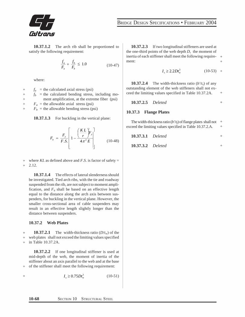
BRIDGE DESIGN SPECIFICATIONS bull FEBRUARY 2004
TABLE 10372A Limiting Width-Thickness Ratios for Solid Rib Arches +
Web Plates
Flange Plates
b = fa = fb = tf = ts = tw =
Description of Component
Without longitudinal stiffiners
With one longitudinal stiffener at the one-third point of the web depth
With two longitudinal stiffeners at the one-third point of the web design
Outstanding element of stiffiners
Web plate equations apply between limits
Plates between webs
Overhang plates
Width +Thickness Limiting Width-Thickness Ratio
Ratio
5000 +pound 60 (10-49)fa
7500 pound 90 (10-50) +D t w fa
10000 pound 120 (10-52) +fa
1625 pound 12 (10-54)b tcent +s fa + fb 3
fb02 pound pound 07 +(10-55)fa + fb 3
4250 pound 47 (10-56) +
fa + fb
centb t f 1625 (10-57)
fa + fb
pound 12 +
width of flange plate or width of outstanding element of web stiffeners (in) + calculated axial compressive stress in the component under consideration (psi) + calculated compressive bending stress in the component under consideration (psi) + flange plate thickness (in) + web stiffener outstanding element thickness (in) + web plate thickness (in) +
SECTION 10 STRUCTURAL STEEL 10-69
BRIDGE DESIGN SPECIFICATIONS bull FEBRUARY 2004
+ 1038 COMPOSITE BEAMS AND GIRDERS +
10381 General
+ 103811 This section pertains to structures comshy
posed of steel beams or girders with concrete slabs connected by shear connectors
103812 General specifications pertaining to the design of concrete and steel structures shall apply to strucshytures utilizing composite girders where such specifications are applicable Composite girders and slabs shall be deshysigned and the stresses computed by the composite moment of inertia method and shall be consistent with the predetershymined properties of the various materials used
+ 103813 The ratio of the modulus of elasticity of steel (29000000 psi) to those of normal weight concrete (W = 145 pcf) of various design strengths shall be as follows
+
+
+
f c
n
f c
= specified compressive strength of concrete as determined by cylinder tests at the age of 28 days (psi)
= ratio of modulus of elasticity of steel to that of concrete The value of n as a function of the specified compressive strength of concrete shall be assumed as follows
= 2000 - 2300 n = 11 2400 - 2800 n = 10 2900 - 3500 n = 9 3600 - 4500 n = 8 4600 - 5900 n = 7 6000 or more n = 6
+ +
+
103814 The effect of creep shall be considered in the design of composite girders which have dead loads acting on the composite section In such structures bendshying stresses and horizontal shears produced by dead loads acting on the composite section shall be computed for n as given above or for this value multiplied by 3 whichshyever gives the higher bending stresses and shears
103815 If concrete with expansive characterisshytics is used composite design should be used with caushytion and provision must be made in the design to accomshymodate the expansion
103816 Composite sections in simple spans and the positive moment regions of continuous spans should
preferably be proportioned so that the neutral axis lies below the top surface of the steel beam Concrete on the tension side of the neutral axis shall not be considered in calculating resisting moments In the negative moment regions of continuous spans only the slab reinforcement can be considered to act compositely with the steel beams in calculating resisting moments Mechanical anchorshyages shall be provided in the composite regions to deshyvelop stresses on the plane joining the concrete and the steel Concrete on the tension side of the neutral axis may be considered in computing moments of inertia for deshyflection calculations for determining stiffness used in + calculating moments and shears and for computing fashytigue stress ranges and fatigue shear ranges as permitted under the provisions of Article1031and 103851
103817 The steel beams or girders especially if not supported by intermediate falsework shall be invesshytigated for stability and strength for the loading applied during the time the concrete is in place and before it has hardened The casting or placing sequence specified in the plans for the composite concrete deck shall be considshyered when calculating the moments and shears on the steel section The maximum flange compression stress shall not exceed the value specified in Table 10321A for partially supported or unsupported compression flanges multiplied by a factor of 14 but not exceed 055Fy The sum of the non-composite and composite dead-load shear stresses in the web shall not exceed the shear-buckling capacity of the web multiplied by a factor of 135 nor the allowable shear stress as follows
Fv = 045CFy le 033Fy (10-57a)
where
+C = constant specified in Article 103442
10382 Shear Connectors
103821 The mechanical means used at the juncshytion of the girder and slab for the purpose of developing the shear resistance necessary to produce composite action shall conform to the specifications of the respecshytive materials The shear connectors shall be of types that + permit a thorough compaction of the concrete in order to ensure that their entire surfaces are in contact with the concrete They shall be capable of resisting both horizonshytal and vertical movement between the concrete and the steel
10-70 SECTION 10 STRUCTURAL STEEL
BRIDGE DESIGN SPECIFICATIONS bull FEBRUARY 2004
103822 The capacity of stud and channel shear connectors welded to the girders is given in Article 10385 Channel shear connectors shall have at least 316-inch fillet welds placed along the heel and toe of the channel
103823 The clear depth of concrete cover over the tops of the shear connectors shall be not less than 2 inches Shear connectors shall penetrate at least 2 inches above bottom of slab
103824 The clear distance between the edge of a girder flange and the edge of the shear connectors shall be not less than 1 inch Adjacent stud shear connectors shall not be closer than 4 diameters center to center
10383 Effective Flange Width
103831 In composite girder construction the asshysumed effective width of the slab as a T-beam flange shall not exceed the following
(1) One-fourth of the span length of the girder (2) The distance center to center of girders (3) Twelve times the least thickness of the slab
103832 For girders having a flange on one side only the effective flange width shall not exceed oneshytwelfth of the span length of the girder or six times the thickness of the slab or one-half the distance center to center of the next girder
10384 Stresses
103841 Maximum compressive and tensile stresses in girders that are not provided with temporary supports during the placing of the permanent dead load shall be the sum of the stresses produced by the dead loads acting on the steel girders alone and the stresses produced by the superimshyposed loads acting on the composite girder When girders are provided with effective intermediate supports that are kept in place until the concrete has attained 75 percent of its required 28-day strength the dead and live load stresses shall be computed on the basis of the composite section
103842 A continuous composite bridge may be built with shear connectors either in the positive moment regions or throughout the length of the bridge The positive moment regions may be designed with composshyite sections as in simple spans Shear connectors shall be
provided in the negative moment portion in which the reinforcement steel embedded in the concrete is considshyered a part of the composite section In case the reinforceshyment steel embedded in the concrete is not used in computing section properties for negative moments shear connectors need not be provided in these portions of the spans but additional anchorage connectors shall be placed in the region of the point of dead load contra-flexure in accordance with Article 1038513 Shear connectors shall be provided in accordance with Article 10385
103843 The minimum longitudinal reinforceshyment including the longitudinal distribution reinforceshyment must equal or exceed one percent of the crossshysectional area of the concrete slab whenever the longitushydinal tensile stress in the concrete slab due to either the construction loads or the design loads exceeds f specifiedt in Article 815211 The area of the concrete slab shall be equal to the structural thickness times the entire width of the bridge deck The required reinforcement shall be No 6 bars or smaller spaced at not more than 12 inches Two-thirds of this required reinforcement is to be placed in the top layer of slab Placement of distribution steel as specified in Article 32410 is waived
103844 When shear connectors are omitted from the negative moment region the longitudinal reinforceshyment shall be extended into the positive moment region beyond the anchorage connectors at least 40 times the reinforcement diameter For epoxy-coated bars the length to be extended into the positive moment region beyond the anchorage connectors should be modified to comply with Article 82523
10385 Shear
103851 Horizontal Shear
The maximum pitch of shear connectors shall not exceed 24 inches except over the interior supports of continuous beams where wider spacing may be used to avoid placing connectors at locations of high stresses in the tension flange
Resistance to horizontal shear shall be provided by meshychanical shear connectors at the junction of the concrete slab and the steel girder The shear connectors shall be mechanical devices placed transversely across the flange
SECTION 10 STRUCTURAL STEEL 10-71
BRIDGE DESIGN SPECIFICATIONS bull FEBRUARY 2004
of the girder spaced at regular or variable intervals The shear connectors shall be designed for fatigue and
+ checked for design strength
1038511 Fatigue
The range of horizontal shear shall be computed by the formula
VrQSr = (10-58)I
where
+ Sr = range of horizontal shear (lbin) at the junction of the slab and girder at the point in the span under consideration
+ Vr = range of shear due to live loads and impact (lb) at any section the range of shear shall be taken as the difference in the minimum and maximum shear envelopes (excluding dead loads)
Q = statical moment about the neutral axis of the composite section of the transformed concrete
+ area (in3) Between points of dead-load contraflexure the static moment about the neushytral axis of the composite section of the area of reinforcement embedded in the concrete may be used unless the transformed concrete area is considered to be fully effective for the negative moment in computing the longitudinal ranges of stress
+ I = moment of inertia of the transformed short-term + composite section (in4) Between points of deadshy
load contraflexure the moment of inertia of the steel girder including the area of reinforcement embedded in the concrete may be used unless the transformed concrete area is considered to be fully effective for the negative moment in
+ computing the longitudinal ranges of stress
+ (In the formula the concrete area is transformed into an equivalent area of steel by dividing the effective concrete flange width by the modular ratio n)
Reference is made to the paper titled ldquoFatigue Strength of Shear Connectorsrdquo by Roger G Slutter and John W Fisher in Highway Research Record No 147 published by the Highway Research Board Washington DC 1966
The allowable range of horizontal shear Zr (lb) on an + individual connector is as follows
Channels
Zr = Bw (10-59)
Welded studs (for Hd ge 4)
Zr = α d2 (10-60)
where
w = length of a channel shear connector (in) mea- + sured in a transverse direction on the flange of a girder
d = diameter of stud (in) + α = 13000 for 100000 cycles +
10600 for 500000 cycles 7850 for 2000000 cycles 5500 for over 2000000 cycles
B = 4000 for 100000 cycles 3000 for 500000 cycles 2400 for 2000000 cycles 2100 for over 2000000 cycles
H = height of stud (in) +
The required pitch of shear connectors is determined by dividing the allowable range of horizontal shear of all connectors at one transverse girder cross-section (ΣZr) by the horizontal range of shear Sr but not to exceed the maximum pitch specified in Article 103851 Over the interior supports of continuous beams the pitch may be modified to avoid placing the connectors at locations of high stresses in the tension flange provided that the total number of connectors remains unchanged
1038512 Design Strength +
The number of connectors so provided for fatigue shall be checked to ensure that adequate connectors are provided for design strength +
10-72 SECTION 10 STRUCTURAL STEEL
BRIDGE DESIGN SPECIFICATIONS bull FEBRUARY 2004
+ The number of shear connectors required shall meet + the following requirement
PN1 Dagger (10-61)f Su
where
N1 = number of connectors between points of maxishymum positive moment and adjacent end supports
+ Su = design strength of the shear connector as given + below (lb)
f = reduction factor = 085 + P = horizontal shear force transferred by shear conshy+ nectors as defined hereafter as P1 or P2
At points of maximum positive moment the force in the slab is taken as the smaller value of the formulas
P1 = AsFy (10-62)
or
P = 085 f centbt (10-63)2 c s
where
As = total area of the steel section including cover shy+ plates (in2) + Fy = specified minimum yield strength of the steel + being used (psi) + fc
cent = specified compressive strength of concrete at + age of 28 days (psi) + b = effective flange width given in Article 10383 (in) + ts = thickness of the concrete slab (in)
The number of connectors N2 required between the points of maximum positive moment and points of adjashy
+ cent maximum negative moment shall meet the followshy+ ing requirement
P + PN Dagger 3
2 (10-64)f Su
At points of maximum negative moment the force in the slab is taken as
r rP3 = As Fy (10-65)
where
Asr = total area of longitudinal reinforcing steel at
the interior support within the effective flange width (in2) +
F r y = specified minimum yield strength of the rein- +
forcing steel (psi) +
The design strength of the shear connector is given + as follows Channels
[ t ) centSu = 550 h+ W fc (10-66)Ł 2 ł
Welded studs (for Hd gt 4)
S = 04 d 2 f c E pound 60000A (10-67)u c sc
where
Ec = modulus of elasticity of the concrete (psi) + Ec = w
3 233 f ccent (10-68)
Su = design strength of individual shear connector + (lb) +
h = average flange thickness of the channel flange (in) +
t = thickness of the web of a channel (in) + W = length of a channel shear connector (in) + fc cent = specified compressive strength of the concrete
at 28 days (psi) + d = diameter of stud (in) + w = unit weight of concrete (pcf) + Asc = area of welded stud cross section (in2) +
SECTION 10 STRUCTURAL STEEL 10-73
BRIDGE DESIGN SPECIFICATIONS bull FEBRUARY 2004
1038513 Additional Connectors to Develop Slab Stresses
The number of additional connectors required at points of contraflexure when reinforcing steel embedded in the concrete is not used in computing section propershyties for negative moments shall be computed by the formula
cN = r
r s r
Z A f
(10-69)
where
Nc = number of additional connectors for each beam at point of contraflexure
+ s rA = total area of longitudinal slab reinforcing steel
for each beam over interior support (in2) + fr = range of stress due to live load plus impact in
the slab reinforcement over the support (psi) (in lieu of more accurate computations fr may be taken as equal to 10000 psi)
+ Zr = allowable range of horizontal shear on an individual shear connector (lb)
The additional connectorsNc shall be placed adjacent to the point of dead load contraflexure within a distance equal to one-third the effective slab width ie placed either side of this point or centered about it It is prefershyable to locate field splices so that they clear the connecshytors
+ 103852 Vertical Shear
The intensity of shearing stress in a composite girder may be determined on the basis that the web of the steel girder carries the total external shear neglecting the effects of the steel flanges and of the concrete slab The shear may be assumed to be uniformly distributed throughout the gross area of the web
10386 Deflection
103861 The provisions of Article 106 in regard to deflections from live load plus impact also shall be applicable to composite girders
103862 When the girders are not provided with falsework or other effective intermediate support during
the placing of the concrete slab the deflection due to the weight of the slab and other permanent dead loads added before the concrete has attained 75 percent of its required 28-day strength shall be computed on the basis of noncomposite action
1039 COMPOSITE BOX GIRDERS
10391 General
103911 This section pertains to the design of simple and continuous bridges of moderate length supshyported by two or more single cell composite box girders The distance center-to-center of flanges of each box should be the same and the average distance center-toshycenter of flanges of adjacent boxes shall be not greater than 12 times and not less than 08 times the distance center-to-center of flanges of each box In addition to the above when nonparallel girders are used the distance center-to-center of adjacent flanges at supports shall be no greater than 135 times and not less than 065 times the distance center-to-center of flanges of each box The cantilever overhang of the deck slab including curbs and parapets shall be limited to 60 percent of the average distance center-to-center of flanges of adjacent boxes but shall in no case exceed 6 feet +
103912 The provisions of these Specifications shall govern where applicable except as specifically modified by Articles 10391 through 10398
10392 Lateral Distribution of Loads for Bending Moment
103921 The live load bending moment for each box girder shall be determined by applying to the girder the fraction WL of a wheel load (both front and rear) determined by the following equation
085WL = 01 + 17 R + (10-70)Nw
where
N wR = (10-71)Numberof Box Girders
10-74 SECTION 10 STRUCTURAL STEEL
BRIDGE DESIGN SPECIFICATIONS bull FEBRUARY 2004
Nw = Wc12 reduced to the nearest whole number + Wc = roadway width between curbs (ft) or barriers
if curbs are not used
+ R shall not be less than 05 or greater than 15
103922 The provision of Article 312 Reducshytion of Load Intensity shall not apply in the design of box girders when using the design load WL given by the above equation
+ 10393 Web Plates
103931 Vertical Shear
The design shear Vw for a web shall be calculated using the following equation
VvVw =
10394 Bottom Flange Plates +
103941 General +
The tension flange and the compression flange shall + be considered completely effective in resisting bending if + its width does not exceed one-fifth the span length If the + flange plate width exceeds one-fifth of the span an + amount equal to one-fifth of the span only shall be + considered effective Effective flange plate width shall + be used to calculate the flange bending stress Full flange + plate width shall be used to calculate the allowable + compressive bending stress
1039412 Deleted +
103942 Compression Flanges Unstiffened
1039421 For unstiffened compression flanges + (10-72) the calculated bending stress shall not exceed the allow- +cosθ
able bending stress Fb (psi) determined by either of the + following equations +
where
b
t F
6140 +le+ Vv = vertical shear (lb) for
θ = angle of inclination of the web plate to the vertical
y
Fb = 055 Fy (10-73) + 103932 Secondary Bending Stresses
+
yy Ft b
F
6140 13300lelt1039321 Web plates may be plumb (90deg to botshy for
tom of flange) or inclined If the inclination of the web plates to a plane normal to bottom flange is no greater than 1 to 4 and the width of the bottom flange is no greater than 20 percent of the span the transverse bendshy b Fy
t
minus13300
2 7160
ing stresses resulting from distortion of the span and the transverse bending stresses resulting from distortion of
πFb 055Fy 0224 Fyminus minussin= + the girder cross section and from vibrations of the bottom plate need not be considered For structures in this catshyegory transverse bending stresses due to supplementary
1
(10-74)loadings such as utilities shall not exceed 5000 psi
b 13300 +ge
t Ffor1039322 For structures exceeding these limits a y
detailed evaluation of the transverse bending stresses due to all causes shall be made These stresses shall be limited
2to a maximum stress or range of stress of 20000 psi
t times106 (10-75) +Fb = 576
b
SECTION 10 STRUCTURAL STEEL 10-75
BRIDGE DESIGN SPECIFICATIONS bull FEBRUARY 2004
where+
+ b = flange width between webs (in) + t = flange thickness (in)
1039422 Deleted+
1039423 Deleted+
1039424 The bt ratio preferably should not exshyceed 60 except in areas of low stress near points of dead load contraflexure
+ 1039425 If the bt ratio exceeds 45 longitudinal + stiffeners may be considered
+ 1039426 Deleted
103943 Compression Flanges Stiffened Longitudinally
1039431 Longitudinal stiffeners shall be at equal spacings across the flange width and shall be proporshytioned so that the moment of inertia of each stiffener about an axis parallel to the flange and at the base of the
+ stiffener Is (in4) shall meet the following requirement
+ I s ge φ t3 f w (10-76)
where
φ = 007 k3n4 for values of n greater than 1 + φ = 0125 k3 for a value of n = 1
tf = thickness of the flange (in) w = width of flange between longitudinal stiffeners
+ or distance from a web to the nearest longitudishynal stiffener (in)
n = number of longitudinal stiffeners k = buckling coefficient which shall not exceed 4
+ 1039432 For the longitudinally stiffened flange + including stiffeners the calculated bending stress shall + not exceed the allowable bending stress Fb (psi) detershy+ mined by either of the following equations
w 3070 kle+ for t Fy
In solving these equations a value of k between 2 and 4 generally should be assumed
F = 055 Fb y
3070 k w for Fy
lt le smaller of 60 or t
w
Fb = 055Fy
minus0224 Fy 1minussin
6650 k minus
2 3580 π
k t
y
+
(10-78)
for 6650
Fy
k le
t w le 60
+
Fb t
2 6= 144 k times10 (10-79) +
+1039433 Deleted
+1039434 Deleted
1039435 When longitudinal stiffeners are used it is preferable to have at least one transverse stiffener placed near the point of dead load contraflexure The stiffener should have a size equal to that of a longitudinal stiffener
1039436 If the longitudinal stiffeners are placed at their maximum wt ratio to be designed for the basic allowable design stresses of 055Fy and the number of longitudinal stiffeners exceeds 2 then transverse stiffenshyers should be considered
1039437 Deleted +
(10-77) +
6650 k + F y
w F
10-76 SECTION 10 STRUCTURAL STEEL
0
BRIDGE DESIGN SPECIFICATIONS bull FEBRUARY 2004
100
90
80
70
60
50
Is bt
40
0
0
10
0
k = 4 k = 4 k = 4
=
4
Ffr = Fy
Ffr = 096 Fy
NO STbtbb = 055 Fy
bbb = 05 Fy
IFFENERS REQUIRED
Fy = 6140
Fy = 0800
=
4
=4
Ffr = 085 Fy
t btbb = 047 Fy Fy = 10060
Note Ffr refebb refersFy is in
rs to Load Factor to Working Stres
1bin
Design s Design
=
k = 56
=
k = 56 k
=
= 56
b b =
05
5 F y
F fr =
Fy
b b =
05
F y
fr =
09
6 F y
F y y
WITHOUT TRANSVERSE STIFFENERS
F
b b =
047
F f
r = 0
85 F
k = 4 k = 4 k = 4
k = 5
= k = 5
=
=
k = 5 WITSH TRANSVERSE TIFFENERS
k
= 1
k = 4= 178
k = 4 = 1
= 1
k = 178
k = 4
k = 178
= = = =
Is = 67bt Is = 00bt 4 Is = 160bt 5 Is = 1bt
5000 10000 15000 0000 5000 0000 5000 40000
b Fyt
FIGURE 103943A Longitudinal StiffenersntildeBox Girder Compression Flange
SECTION 10 STRUCTURAL STEEL 10-77
BRIDGE DESIGN SPECIFICATIONS bull FEBRUARY 2004
3
2 5
2
a b
1 5
1
0 5
0
( fs 0 47 Fy) (Fs 0 85 Fy)
b t
Fy
Is for longitudinal stiffeners 8 t3w (in 4)
k1 4 k1 2 25
k1 2 25k1 4
k1 2 5 k1 4
k1 1 78
k1 1 78
k1 2 78k1 4
2
5
5
4
4
4
3
3
3
2
2
2
3
3
4
3
4 4
5 5 k1 4k1 2 78
k1 2 5
k1 4
k1 2
2
2
Note fs refers to Working Stress Design Fs refers to Load Factor Design Fy is in lbin 2
a b
( fs 0 47 Fy) (Fs 0 85 Fy)
a b
( fs 0 55 Fy) (Fs Fy)
a b ( fs 0 53 Fy) (Fs 0 9 Fy)
It b f Fy
It b f Fy
( fs 0 53 Fy) (Fs 0 9 Fy)
It b f Fy
( fs 0 55 Fy) (Fs Fy)
k1 4
0 09
0 08
0 07
0 0
0 05
0 04
It b f Fy
0 03
0 02
0 01
10000 15000 20000 25000 30000 35000 40000 45000
FIGURE 103943B Spacing and Size of Transverse Stiffeners (for Flange Stiffened Longitudinally and Transversely)
10-78 SECTION 10 STRUCTURAL STEEL
0
BRIDGE DESIGN SPECIFICATIONS bull FEBRUARY 2004
103944 Compression Flanges Stiffened Longitudinally and Transversely
1039441 The longitudinal stiffeners shall be at equal spacings across the flange width and shall be proportioned so that the moment of inertia of each stiffshyeners about an axis parallel to the flange and at the base
+ of the stiffeners meet the following requirement
I s ge 8t3 f w (10-80)
1039442 The transverse stiffeners shall be proshyportioned so that the moment of inertia of each stiffener about an axis through the centroid of the section and parallel
+ to its bottom edge meets the following requirement
3 3 fs Af+ It ge 010 (n + 1) w (10-81)E do
where
Af = area of bottom flange including longitudinal + stiffeners (in2) + do = spacing of transverse stiffeners (in)
fs = maximum longitudinal bending stress in the flange of the panels on either side of the transshy
+ verse stiffeners (psi) + E = modulus of elasticity of steel (psi)
+ 1039443 For the flange including stiffeners the + calculated bending stress shall not exceed the allowable + bending stress Fb (psi) determined by either of the + following equations
w 3070 k1+ lefor t Fy
+ Fb = 055 Fy (10-82)
3070 k1 w 6650 k1 le or + lt smaller of 60for Fy t F y
w F 6650 k1 minus y
π t F = 055F minus0224 F 1minussinb y y + 2 3580 k1
(10-83)
6650 k1 wle le 60 +for Fy t
t 2
6Fb = 144 k1 times10 (10-84) + w
where
( ) [ ( ) ( ) 1
1 22
2
1 +
+ =
a bn
a bk ]
( ) [ 1 ]011 873
2
++
+
n (10-85) +
1039444 Deleted +
1039445 Deleted +
1039446 The maximum value of the buckling coefficient k1 shall be 4 When k1 has its maximum value the transverse stiffeners shall have a spacing a equal to or less than 4w If the ratio ab exceeds 3 transverse stiffeners are not necessary
1039447 The transverse stiffeners need not be connected to the flange plate but shall be connected to the webs of the box and to each longitudinal stiffener The connection to the web shall be designed to resist the vertical force determined by the formula
R = FySs
w (10-86)2 b
where
Ss = section modulus of the transverse stiffener (in3) +
SECTION 10 STRUCTURAL STEEL 10-79
BRIDGE DESIGN SPECIFICATIONS bull FEBRUARY 2004
1039448 The connection to each longitudinal stiffener shall be designed to resist the vertical force determined by the formula
F S =Rs n
y
bs
(10-87)
103945 Compression Flange Stiffeners General
+ 1039451 The width-thickness ratio (bts) of any outstanding element of the flange stiffeners shall not
+ exceed the limiting values specified in Table 10345A
1039452 Longitudinal stiffeners shall be exshytended to locations where the maximum stress in the flange does not exceed that allowed for base metal adjacent to or connected by fillet welds
+ 10395 Flange to Web Welds
The total effective thickness of the web-flange welds + shall be not less than the thickness of the web Regardless
of the type weld used welds shall be deposited on both sides of the connecting flange or web plate
10396 Diaphragms
103961 Diaphragms cross-frames or other means shall be provided within the box girders at each support to resist transverse rotation displacement and distortion
103962 Intermediate diaphragms or cross-frames are not required for steel box girder bridges designed in accordance with this specification
10397 Lateral Bracing
Generally no lateral bracing system is required beshytween box girders A horizontal wind load of 50 pounds per square foot shall be applied to the area of the supershystructure exposed in elevation Half of the resulting force shall be applied in the plane of the bottom flange The section assumed to resist the horizontal load shall consist of the bottom flange acting as a web and 12 times the thickness of the webs acting as flanges A lateral bracing system shall be provided if the combined stresses due to the specified horizontal force and dead load of steel and deck exceed 150 percent of the allowable design stress
10398 Access and Drainage
Consistent with climate location and materials considshyeration shall be given to the providing of manholes or other openings either in the deck slab or in the steel box for form removal inspection maintenance drainage etc
1040 HYBRID GIRDERS
10401 General
104011 This section pertains to the design of girders that utilize a lower strength steel in the web than in one or both of the flanges It applies to composite and noncomposite plate girders and composite box girders At any cross section where the bending stress in either flange exceeds 55 percent of minimum specified yield strength of the web steel the compression-flange area shall not be less than the tension-flange area The top-flange area shall include the transformed area of any portion of the slab or reinforcing steel that is considered to act compositely with the steel girder
104012 The provisions of these Specifications shall govern where applicable except as specifically modified by Articles 10401 through 10404
+
10402 Allowable Stresses
104021 Bending
1040211 The bending stress in the web may exceed the allowable stress for the web steel provided that the stress in each flange does not exceed the allowshyable stress from Articles 103 or 1032 for the steel in that flange multiplied by the reduction factor R
( ) ( ) ( ψ )βψ
ψαψαβψ minus+
+minusminusminus=
36 31
1 2
R (10-89)
(See Figures 104021A and 104021B)
where
α = specified minimum yield strength of the web divided by the specified minimum yield strength of the tension flange
β = area of the web divided by the area of the tension flange
Bottom flange of orthotropic deck bridge
+
10-80 SECTION 10 STRUCTURAL STEEL
BRIDGE DESIGN SPECIFICATIONS bull FEBRUARY 2004
103822 The capacity of stud and channel shear connectors welded to the girders is given in Article 10385 Channel shear connectors shall have at least 316-inch fillet welds placed along the heel and toe of the channel
103823 The clear depth of concrete cover over the tops of the shear connectors shall be not less than 2 inches Shear connectors shall penetrate at least 2 inches above bottom of slab
103824 The clear distance between the edge of a girder flange and the edge of the shear connectors shall be not less than 1 inch Adjacent stud shear connectors shall not be closer than 4 diameters center to center
10383 Effective Flange Width
103831 In composite girder construction the asshysumed effective width of the slab as a T-beam flange shall not exceed the following
(1) One-fourth of the span length of the girder (2) The distance center to center of girders (3) Twelve times the least thickness of the slab
103832 For girders having a flange on one side only the effective flange width shall not exceed oneshytwelfth of the span length of the girder or six times the thickness of the slab or one-half the distance center to center of the next girder
10384 Stresses
103841 Maximum compressive and tensile stresses in girders that are not provided with temporary supports during the placing of the permanent dead load shall be the sum of the stresses produced by the dead loads acting on the steel girders alone and the stresses produced by the superimshyposed loads acting on the composite girder When girders are provided with effective intermediate supports that are kept in place until the concrete has attained 75 percent of its required 28-day strength the dead and live load stresses shall be computed on the basis of the composite section
103842 A continuous composite bridge may be built with shear connectors either in the positive moment regions or throughout the length of the bridge The positive moment regions may be designed with composshyite sections as in simple spans Shear connectors shall be
provided in the negative moment portion in which the reinforcement steel embedded in the concrete is considshyered a part of the composite section In case the reinforceshyment steel embedded in the concrete is not used in computing section properties for negative moments shear connectors need not be provided in these portions of the spans but additional anchorage connectors shall be placed in the region of the point of dead load contra-flexure in accordance with Article 1038513 Shear connectors shall be provided in accordance with Article 10385
103843 The minimum longitudinal reinforceshyment including the longitudinal distribution reinforceshyment must equal or exceed one percent of the crossshysectional area of the concrete slab whenever the longitushydinal tensile stress in the concrete slab due to either the construction loads or the design loads exceeds f specifiedt in Article 815211 The area of the concrete slab shall be equal to the structural thickness times the entire width of the bridge deck The required reinforcement shall be No 6 bars or smaller spaced at not more than 12 inches Two-thirds of this required reinforcement is to be placed in the top layer of slab Placement of distribution steel as specified in Article 32410 is waived
103844 When shear connectors are omitted from the negative moment region the longitudinal reinforceshyment shall be extended into the positive moment region beyond the anchorage connectors at least 40 times the reinforcement diameter For epoxy-coated bars the length to be extended into the positive moment region beyond the anchorage connectors should be modified to comply with Article 82523
10385 Shear
103851 Horizontal Shear
The maximum pitch of shear connectors shall not exceed 24 inches except over the interior supports of continuous beams where wider spacing may be used to avoid placing connectors at locations of high stresses in the tension flange
Resistance to horizontal shear shall be provided by meshychanical shear connectors at the junction of the concrete slab and the steel girder The shear connectors shall be mechanical devices placed transversely across the flange
SECTION 10 STRUCTURAL STEEL 10-71
BRIDGE DESIGN SPECIFICATIONS bull FEBRUARY 2004
of the girder spaced at regular or variable intervals The shear connectors shall be designed for fatigue and
+ checked for design strength
1038511 Fatigue
The range of horizontal shear shall be computed by the formula
VrQSr = (10-58)I
where
+ Sr = range of horizontal shear (lbin) at the junction of the slab and girder at the point in the span under consideration
+ Vr = range of shear due to live loads and impact (lb) at any section the range of shear shall be taken as the difference in the minimum and maximum shear envelopes (excluding dead loads)
Q = statical moment about the neutral axis of the composite section of the transformed concrete
+ area (in3) Between points of dead-load contraflexure the static moment about the neushytral axis of the composite section of the area of reinforcement embedded in the concrete may be used unless the transformed concrete area is considered to be fully effective for the negative moment in computing the longitudinal ranges of stress
+ I = moment of inertia of the transformed short-term + composite section (in4) Between points of deadshy
load contraflexure the moment of inertia of the steel girder including the area of reinforcement embedded in the concrete may be used unless the transformed concrete area is considered to be fully effective for the negative moment in
+ computing the longitudinal ranges of stress
+ (In the formula the concrete area is transformed into an equivalent area of steel by dividing the effective concrete flange width by the modular ratio n)
Reference is made to the paper titled ldquoFatigue Strength of Shear Connectorsrdquo by Roger G Slutter and John W Fisher in Highway Research Record No 147 published by the Highway Research Board Washington DC 1966
The allowable range of horizontal shear Zr (lb) on an + individual connector is as follows
Channels
Zr = Bw (10-59)
Welded studs (for Hd ge 4)
Zr = α d2 (10-60)
where
w = length of a channel shear connector (in) mea- + sured in a transverse direction on the flange of a girder
d = diameter of stud (in) + α = 13000 for 100000 cycles +
10600 for 500000 cycles 7850 for 2000000 cycles 5500 for over 2000000 cycles
B = 4000 for 100000 cycles 3000 for 500000 cycles 2400 for 2000000 cycles 2100 for over 2000000 cycles
H = height of stud (in) +
The required pitch of shear connectors is determined by dividing the allowable range of horizontal shear of all connectors at one transverse girder cross-section (ΣZr) by the horizontal range of shear Sr but not to exceed the maximum pitch specified in Article 103851 Over the interior supports of continuous beams the pitch may be modified to avoid placing the connectors at locations of high stresses in the tension flange provided that the total number of connectors remains unchanged
1038512 Design Strength +
The number of connectors so provided for fatigue shall be checked to ensure that adequate connectors are provided for design strength +
10-72 SECTION 10 STRUCTURAL STEEL
BRIDGE DESIGN SPECIFICATIONS bull FEBRUARY 2004
+ The number of shear connectors required shall meet + the following requirement
PN1 Dagger (10-61)f Su
where
N1 = number of connectors between points of maxishymum positive moment and adjacent end supports
+ Su = design strength of the shear connector as given + below (lb)
f = reduction factor = 085 + P = horizontal shear force transferred by shear conshy+ nectors as defined hereafter as P1 or P2
At points of maximum positive moment the force in the slab is taken as the smaller value of the formulas
P1 = AsFy (10-62)
or
P = 085 f centbt (10-63)2 c s
where
As = total area of the steel section including cover shy+ plates (in2) + Fy = specified minimum yield strength of the steel + being used (psi) + fc
cent = specified compressive strength of concrete at + age of 28 days (psi) + b = effective flange width given in Article 10383 (in) + ts = thickness of the concrete slab (in)
The number of connectors N2 required between the points of maximum positive moment and points of adjashy
+ cent maximum negative moment shall meet the followshy+ ing requirement
P + PN Dagger 3
2 (10-64)f Su
At points of maximum negative moment the force in the slab is taken as
r rP3 = As Fy (10-65)
where
Asr = total area of longitudinal reinforcing steel at
the interior support within the effective flange width (in2) +
F r y = specified minimum yield strength of the rein- +
forcing steel (psi) +
The design strength of the shear connector is given + as follows Channels
[ t ) centSu = 550 h+ W fc (10-66)Ł 2 ł
Welded studs (for Hd gt 4)
S = 04 d 2 f c E pound 60000A (10-67)u c sc
where
Ec = modulus of elasticity of the concrete (psi) + Ec = w
3 233 f ccent (10-68)
Su = design strength of individual shear connector + (lb) +
h = average flange thickness of the channel flange (in) +
t = thickness of the web of a channel (in) + W = length of a channel shear connector (in) + fc cent = specified compressive strength of the concrete
at 28 days (psi) + d = diameter of stud (in) + w = unit weight of concrete (pcf) + Asc = area of welded stud cross section (in2) +
SECTION 10 STRUCTURAL STEEL 10-73
BRIDGE DESIGN SPECIFICATIONS bull FEBRUARY 2004
1038513 Additional Connectors to Develop Slab Stresses
The number of additional connectors required at points of contraflexure when reinforcing steel embedded in the concrete is not used in computing section propershyties for negative moments shall be computed by the formula
cN = r
r s r
Z A f
(10-69)
where
Nc = number of additional connectors for each beam at point of contraflexure
+ s rA = total area of longitudinal slab reinforcing steel
for each beam over interior support (in2) + fr = range of stress due to live load plus impact in
the slab reinforcement over the support (psi) (in lieu of more accurate computations fr may be taken as equal to 10000 psi)
+ Zr = allowable range of horizontal shear on an individual shear connector (lb)
The additional connectorsNc shall be placed adjacent to the point of dead load contraflexure within a distance equal to one-third the effective slab width ie placed either side of this point or centered about it It is prefershyable to locate field splices so that they clear the connecshytors
+ 103852 Vertical Shear
The intensity of shearing stress in a composite girder may be determined on the basis that the web of the steel girder carries the total external shear neglecting the effects of the steel flanges and of the concrete slab The shear may be assumed to be uniformly distributed throughout the gross area of the web
10386 Deflection
103861 The provisions of Article 106 in regard to deflections from live load plus impact also shall be applicable to composite girders
103862 When the girders are not provided with falsework or other effective intermediate support during
the placing of the concrete slab the deflection due to the weight of the slab and other permanent dead loads added before the concrete has attained 75 percent of its required 28-day strength shall be computed on the basis of noncomposite action
1039 COMPOSITE BOX GIRDERS
10391 General
103911 This section pertains to the design of simple and continuous bridges of moderate length supshyported by two or more single cell composite box girders The distance center-to-center of flanges of each box should be the same and the average distance center-toshycenter of flanges of adjacent boxes shall be not greater than 12 times and not less than 08 times the distance center-to-center of flanges of each box In addition to the above when nonparallel girders are used the distance center-to-center of adjacent flanges at supports shall be no greater than 135 times and not less than 065 times the distance center-to-center of flanges of each box The cantilever overhang of the deck slab including curbs and parapets shall be limited to 60 percent of the average distance center-to-center of flanges of adjacent boxes but shall in no case exceed 6 feet +
103912 The provisions of these Specifications shall govern where applicable except as specifically modified by Articles 10391 through 10398
10392 Lateral Distribution of Loads for Bending Moment
103921 The live load bending moment for each box girder shall be determined by applying to the girder the fraction WL of a wheel load (both front and rear) determined by the following equation
085WL = 01 + 17 R + (10-70)Nw
where
N wR = (10-71)Numberof Box Girders
10-74 SECTION 10 STRUCTURAL STEEL
BRIDGE DESIGN SPECIFICATIONS bull FEBRUARY 2004
Nw = Wc12 reduced to the nearest whole number + Wc = roadway width between curbs (ft) or barriers
if curbs are not used
+ R shall not be less than 05 or greater than 15
103922 The provision of Article 312 Reducshytion of Load Intensity shall not apply in the design of box girders when using the design load WL given by the above equation
+ 10393 Web Plates
103931 Vertical Shear
The design shear Vw for a web shall be calculated using the following equation
VvVw =
10394 Bottom Flange Plates +
103941 General +
The tension flange and the compression flange shall + be considered completely effective in resisting bending if + its width does not exceed one-fifth the span length If the + flange plate width exceeds one-fifth of the span an + amount equal to one-fifth of the span only shall be + considered effective Effective flange plate width shall + be used to calculate the flange bending stress Full flange + plate width shall be used to calculate the allowable + compressive bending stress
1039412 Deleted +
103942 Compression Flanges Unstiffened
1039421 For unstiffened compression flanges + (10-72) the calculated bending stress shall not exceed the allow- +cosθ
able bending stress Fb (psi) determined by either of the + following equations +
where
b
t F
6140 +le+ Vv = vertical shear (lb) for
θ = angle of inclination of the web plate to the vertical
y
Fb = 055 Fy (10-73) + 103932 Secondary Bending Stresses
+
yy Ft b
F
6140 13300lelt1039321 Web plates may be plumb (90deg to botshy for
tom of flange) or inclined If the inclination of the web plates to a plane normal to bottom flange is no greater than 1 to 4 and the width of the bottom flange is no greater than 20 percent of the span the transverse bendshy b Fy
t
minus13300
2 7160
ing stresses resulting from distortion of the span and the transverse bending stresses resulting from distortion of
πFb 055Fy 0224 Fyminus minussin= + the girder cross section and from vibrations of the bottom plate need not be considered For structures in this catshyegory transverse bending stresses due to supplementary
1
(10-74)loadings such as utilities shall not exceed 5000 psi
b 13300 +ge
t Ffor1039322 For structures exceeding these limits a y
detailed evaluation of the transverse bending stresses due to all causes shall be made These stresses shall be limited
2to a maximum stress or range of stress of 20000 psi
t times106 (10-75) +Fb = 576
b
SECTION 10 STRUCTURAL STEEL 10-75
BRIDGE DESIGN SPECIFICATIONS bull FEBRUARY 2004
where+
+ b = flange width between webs (in) + t = flange thickness (in)
1039422 Deleted+
1039423 Deleted+
1039424 The bt ratio preferably should not exshyceed 60 except in areas of low stress near points of dead load contraflexure
+ 1039425 If the bt ratio exceeds 45 longitudinal + stiffeners may be considered
+ 1039426 Deleted
103943 Compression Flanges Stiffened Longitudinally
1039431 Longitudinal stiffeners shall be at equal spacings across the flange width and shall be proporshytioned so that the moment of inertia of each stiffener about an axis parallel to the flange and at the base of the
+ stiffener Is (in4) shall meet the following requirement
+ I s ge φ t3 f w (10-76)
where
φ = 007 k3n4 for values of n greater than 1 + φ = 0125 k3 for a value of n = 1
tf = thickness of the flange (in) w = width of flange between longitudinal stiffeners
+ or distance from a web to the nearest longitudishynal stiffener (in)
n = number of longitudinal stiffeners k = buckling coefficient which shall not exceed 4
+ 1039432 For the longitudinally stiffened flange + including stiffeners the calculated bending stress shall + not exceed the allowable bending stress Fb (psi) detershy+ mined by either of the following equations
w 3070 kle+ for t Fy
In solving these equations a value of k between 2 and 4 generally should be assumed
F = 055 Fb y
3070 k w for Fy
lt le smaller of 60 or t
w
Fb = 055Fy
minus0224 Fy 1minussin
6650 k minus
2 3580 π
k t
y
+
(10-78)
for 6650
Fy
k le
t w le 60
+
Fb t
2 6= 144 k times10 (10-79) +
+1039433 Deleted
+1039434 Deleted
1039435 When longitudinal stiffeners are used it is preferable to have at least one transverse stiffener placed near the point of dead load contraflexure The stiffener should have a size equal to that of a longitudinal stiffener
1039436 If the longitudinal stiffeners are placed at their maximum wt ratio to be designed for the basic allowable design stresses of 055Fy and the number of longitudinal stiffeners exceeds 2 then transverse stiffenshyers should be considered
1039437 Deleted +
(10-77) +
6650 k + F y
w F
10-76 SECTION 10 STRUCTURAL STEEL
0
BRIDGE DESIGN SPECIFICATIONS bull FEBRUARY 2004
100
90
80
70
60
50
Is bt
40
0
0
10
0
k = 4 k = 4 k = 4
=
4
Ffr = Fy
Ffr = 096 Fy
NO STbtbb = 055 Fy
bbb = 05 Fy
IFFENERS REQUIRED
Fy = 6140
Fy = 0800
=
4
=4
Ffr = 085 Fy
t btbb = 047 Fy Fy = 10060
Note Ffr refebb refersFy is in
rs to Load Factor to Working Stres
1bin
Design s Design
=
k = 56
=
k = 56 k
=
= 56
b b =
05
5 F y
F fr =
Fy
b b =
05
F y
fr =
09
6 F y
F y y
WITHOUT TRANSVERSE STIFFENERS
F
b b =
047
F f
r = 0
85 F
k = 4 k = 4 k = 4
k = 5
= k = 5
=
=
k = 5 WITSH TRANSVERSE TIFFENERS
k
= 1
k = 4= 178
k = 4 = 1
= 1
k = 178
k = 4
k = 178
= = = =
Is = 67bt Is = 00bt 4 Is = 160bt 5 Is = 1bt
5000 10000 15000 0000 5000 0000 5000 40000
b Fyt
FIGURE 103943A Longitudinal StiffenersntildeBox Girder Compression Flange
SECTION 10 STRUCTURAL STEEL 10-77
BRIDGE DESIGN SPECIFICATIONS bull FEBRUARY 2004
3
2 5
2
a b
1 5
1
0 5
0
( fs 0 47 Fy) (Fs 0 85 Fy)
b t
Fy
Is for longitudinal stiffeners 8 t3w (in 4)
k1 4 k1 2 25
k1 2 25k1 4
k1 2 5 k1 4
k1 1 78
k1 1 78
k1 2 78k1 4
2
5
5
4
4
4
3
3
3
2
2
2
3
3
4
3
4 4
5 5 k1 4k1 2 78
k1 2 5
k1 4
k1 2
2
2
Note fs refers to Working Stress Design Fs refers to Load Factor Design Fy is in lbin 2
a b
( fs 0 47 Fy) (Fs 0 85 Fy)
a b
( fs 0 55 Fy) (Fs Fy)
a b ( fs 0 53 Fy) (Fs 0 9 Fy)
It b f Fy
It b f Fy
( fs 0 53 Fy) (Fs 0 9 Fy)
It b f Fy
( fs 0 55 Fy) (Fs Fy)
k1 4
0 09
0 08
0 07
0 0
0 05
0 04
It b f Fy
0 03
0 02
0 01
10000 15000 20000 25000 30000 35000 40000 45000
FIGURE 103943B Spacing and Size of Transverse Stiffeners (for Flange Stiffened Longitudinally and Transversely)
10-78 SECTION 10 STRUCTURAL STEEL
0
BRIDGE DESIGN SPECIFICATIONS bull FEBRUARY 2004
103944 Compression Flanges Stiffened Longitudinally and Transversely
1039441 The longitudinal stiffeners shall be at equal spacings across the flange width and shall be proportioned so that the moment of inertia of each stiffshyeners about an axis parallel to the flange and at the base
+ of the stiffeners meet the following requirement
I s ge 8t3 f w (10-80)
1039442 The transverse stiffeners shall be proshyportioned so that the moment of inertia of each stiffener about an axis through the centroid of the section and parallel
+ to its bottom edge meets the following requirement
3 3 fs Af+ It ge 010 (n + 1) w (10-81)E do
where
Af = area of bottom flange including longitudinal + stiffeners (in2) + do = spacing of transverse stiffeners (in)
fs = maximum longitudinal bending stress in the flange of the panels on either side of the transshy
+ verse stiffeners (psi) + E = modulus of elasticity of steel (psi)
+ 1039443 For the flange including stiffeners the + calculated bending stress shall not exceed the allowable + bending stress Fb (psi) determined by either of the + following equations
w 3070 k1+ lefor t Fy
+ Fb = 055 Fy (10-82)
3070 k1 w 6650 k1 le or + lt smaller of 60for Fy t F y
w F 6650 k1 minus y
π t F = 055F minus0224 F 1minussinb y y + 2 3580 k1
(10-83)
6650 k1 wle le 60 +for Fy t
t 2
6Fb = 144 k1 times10 (10-84) + w
where
( ) [ ( ) ( ) 1
1 22
2
1 +
+ =
a bn
a bk ]
( ) [ 1 ]011 873
2
++
+
n (10-85) +
1039444 Deleted +
1039445 Deleted +
1039446 The maximum value of the buckling coefficient k1 shall be 4 When k1 has its maximum value the transverse stiffeners shall have a spacing a equal to or less than 4w If the ratio ab exceeds 3 transverse stiffeners are not necessary
1039447 The transverse stiffeners need not be connected to the flange plate but shall be connected to the webs of the box and to each longitudinal stiffener The connection to the web shall be designed to resist the vertical force determined by the formula
R = FySs
w (10-86)2 b
where
Ss = section modulus of the transverse stiffener (in3) +
SECTION 10 STRUCTURAL STEEL 10-79
BRIDGE DESIGN SPECIFICATIONS bull FEBRUARY 2004
1039448 The connection to each longitudinal stiffener shall be designed to resist the vertical force determined by the formula
F S =Rs n
y
bs
(10-87)
103945 Compression Flange Stiffeners General
+ 1039451 The width-thickness ratio (bts) of any outstanding element of the flange stiffeners shall not
+ exceed the limiting values specified in Table 10345A
1039452 Longitudinal stiffeners shall be exshytended to locations where the maximum stress in the flange does not exceed that allowed for base metal adjacent to or connected by fillet welds
+ 10395 Flange to Web Welds
The total effective thickness of the web-flange welds + shall be not less than the thickness of the web Regardless
of the type weld used welds shall be deposited on both sides of the connecting flange or web plate
10396 Diaphragms
103961 Diaphragms cross-frames or other means shall be provided within the box girders at each support to resist transverse rotation displacement and distortion
103962 Intermediate diaphragms or cross-frames are not required for steel box girder bridges designed in accordance with this specification
10397 Lateral Bracing
Generally no lateral bracing system is required beshytween box girders A horizontal wind load of 50 pounds per square foot shall be applied to the area of the supershystructure exposed in elevation Half of the resulting force shall be applied in the plane of the bottom flange The section assumed to resist the horizontal load shall consist of the bottom flange acting as a web and 12 times the thickness of the webs acting as flanges A lateral bracing system shall be provided if the combined stresses due to the specified horizontal force and dead load of steel and deck exceed 150 percent of the allowable design stress
10398 Access and Drainage
Consistent with climate location and materials considshyeration shall be given to the providing of manholes or other openings either in the deck slab or in the steel box for form removal inspection maintenance drainage etc
1040 HYBRID GIRDERS
10401 General
104011 This section pertains to the design of girders that utilize a lower strength steel in the web than in one or both of the flanges It applies to composite and noncomposite plate girders and composite box girders At any cross section where the bending stress in either flange exceeds 55 percent of minimum specified yield strength of the web steel the compression-flange area shall not be less than the tension-flange area The top-flange area shall include the transformed area of any portion of the slab or reinforcing steel that is considered to act compositely with the steel girder
104012 The provisions of these Specifications shall govern where applicable except as specifically modified by Articles 10401 through 10404
+
10402 Allowable Stresses
104021 Bending
1040211 The bending stress in the web may exceed the allowable stress for the web steel provided that the stress in each flange does not exceed the allowshyable stress from Articles 103 or 1032 for the steel in that flange multiplied by the reduction factor R
( ) ( ) ( ψ )βψ
ψαψαβψ minus+
+minusminusminus=
36 31
1 2
R (10-89)
(See Figures 104021A and 104021B)
where
α = specified minimum yield strength of the web divided by the specified minimum yield strength of the tension flange
β = area of the web divided by the area of the tension flange
Bottom flange of orthotropic deck bridge
+
10-80 SECTION 10 STRUCTURAL STEEL

BRIDGE DESIGN SPECIFICATIONS bull FEBRUARY 2004
of the girder spaced at regular or variable intervals The shear connectors shall be designed for fatigue and
+ checked for design strength
1038511 Fatigue
The range of horizontal shear shall be computed by the formula
VrQSr = (10-58)I
where
+ Sr = range of horizontal shear (lbin) at the junction of the slab and girder at the point in the span under consideration
+ Vr = range of shear due to live loads and impact (lb) at any section the range of shear shall be taken as the difference in the minimum and maximum shear envelopes (excluding dead loads)
Q = statical moment about the neutral axis of the composite section of the transformed concrete
+ area (in3) Between points of dead-load contraflexure the static moment about the neushytral axis of the composite section of the area of reinforcement embedded in the concrete may be used unless the transformed concrete area is considered to be fully effective for the negative moment in computing the longitudinal ranges of stress
+ I = moment of inertia of the transformed short-term + composite section (in4) Between points of deadshy
load contraflexure the moment of inertia of the steel girder including the area of reinforcement embedded in the concrete may be used unless the transformed concrete area is considered to be fully effective for the negative moment in
+ computing the longitudinal ranges of stress
+ (In the formula the concrete area is transformed into an equivalent area of steel by dividing the effective concrete flange width by the modular ratio n)
Reference is made to the paper titled ldquoFatigue Strength of Shear Connectorsrdquo by Roger G Slutter and John W Fisher in Highway Research Record No 147 published by the Highway Research Board Washington DC 1966
The allowable range of horizontal shear Zr (lb) on an + individual connector is as follows
Channels
Zr = Bw (10-59)
Welded studs (for Hd ge 4)
Zr = α d2 (10-60)
where
w = length of a channel shear connector (in) mea- + sured in a transverse direction on the flange of a girder
d = diameter of stud (in) + α = 13000 for 100000 cycles +
10600 for 500000 cycles 7850 for 2000000 cycles 5500 for over 2000000 cycles
B = 4000 for 100000 cycles 3000 for 500000 cycles 2400 for 2000000 cycles 2100 for over 2000000 cycles
H = height of stud (in) +
The required pitch of shear connectors is determined by dividing the allowable range of horizontal shear of all connectors at one transverse girder cross-section (ΣZr) by the horizontal range of shear Sr but not to exceed the maximum pitch specified in Article 103851 Over the interior supports of continuous beams the pitch may be modified to avoid placing the connectors at locations of high stresses in the tension flange provided that the total number of connectors remains unchanged
1038512 Design Strength +
The number of connectors so provided for fatigue shall be checked to ensure that adequate connectors are provided for design strength +
10-72 SECTION 10 STRUCTURAL STEEL
BRIDGE DESIGN SPECIFICATIONS bull FEBRUARY 2004
+ The number of shear connectors required shall meet + the following requirement
PN1 Dagger (10-61)f Su
where
N1 = number of connectors between points of maxishymum positive moment and adjacent end supports
+ Su = design strength of the shear connector as given + below (lb)
f = reduction factor = 085 + P = horizontal shear force transferred by shear conshy+ nectors as defined hereafter as P1 or P2
At points of maximum positive moment the force in the slab is taken as the smaller value of the formulas
P1 = AsFy (10-62)
or
P = 085 f centbt (10-63)2 c s
where
As = total area of the steel section including cover shy+ plates (in2) + Fy = specified minimum yield strength of the steel + being used (psi) + fc
cent = specified compressive strength of concrete at + age of 28 days (psi) + b = effective flange width given in Article 10383 (in) + ts = thickness of the concrete slab (in)
The number of connectors N2 required between the points of maximum positive moment and points of adjashy
+ cent maximum negative moment shall meet the followshy+ ing requirement
P + PN Dagger 3
2 (10-64)f Su
At points of maximum negative moment the force in the slab is taken as
r rP3 = As Fy (10-65)
where
Asr = total area of longitudinal reinforcing steel at
the interior support within the effective flange width (in2) +
F r y = specified minimum yield strength of the rein- +
forcing steel (psi) +
The design strength of the shear connector is given + as follows Channels
[ t ) centSu = 550 h+ W fc (10-66)Ł 2 ł
Welded studs (for Hd gt 4)
S = 04 d 2 f c E pound 60000A (10-67)u c sc
where
Ec = modulus of elasticity of the concrete (psi) + Ec = w
3 233 f ccent (10-68)
Su = design strength of individual shear connector + (lb) +
h = average flange thickness of the channel flange (in) +
t = thickness of the web of a channel (in) + W = length of a channel shear connector (in) + fc cent = specified compressive strength of the concrete
at 28 days (psi) + d = diameter of stud (in) + w = unit weight of concrete (pcf) + Asc = area of welded stud cross section (in2) +
SECTION 10 STRUCTURAL STEEL 10-73
BRIDGE DESIGN SPECIFICATIONS bull FEBRUARY 2004
1038513 Additional Connectors to Develop Slab Stresses
The number of additional connectors required at points of contraflexure when reinforcing steel embedded in the concrete is not used in computing section propershyties for negative moments shall be computed by the formula
cN = r
r s r
Z A f
(10-69)
where
Nc = number of additional connectors for each beam at point of contraflexure
+ s rA = total area of longitudinal slab reinforcing steel
for each beam over interior support (in2) + fr = range of stress due to live load plus impact in
the slab reinforcement over the support (psi) (in lieu of more accurate computations fr may be taken as equal to 10000 psi)
+ Zr = allowable range of horizontal shear on an individual shear connector (lb)
The additional connectorsNc shall be placed adjacent to the point of dead load contraflexure within a distance equal to one-third the effective slab width ie placed either side of this point or centered about it It is prefershyable to locate field splices so that they clear the connecshytors
+ 103852 Vertical Shear
The intensity of shearing stress in a composite girder may be determined on the basis that the web of the steel girder carries the total external shear neglecting the effects of the steel flanges and of the concrete slab The shear may be assumed to be uniformly distributed throughout the gross area of the web
10386 Deflection
103861 The provisions of Article 106 in regard to deflections from live load plus impact also shall be applicable to composite girders
103862 When the girders are not provided with falsework or other effective intermediate support during
the placing of the concrete slab the deflection due to the weight of the slab and other permanent dead loads added before the concrete has attained 75 percent of its required 28-day strength shall be computed on the basis of noncomposite action
1039 COMPOSITE BOX GIRDERS
10391 General
103911 This section pertains to the design of simple and continuous bridges of moderate length supshyported by two or more single cell composite box girders The distance center-to-center of flanges of each box should be the same and the average distance center-toshycenter of flanges of adjacent boxes shall be not greater than 12 times and not less than 08 times the distance center-to-center of flanges of each box In addition to the above when nonparallel girders are used the distance center-to-center of adjacent flanges at supports shall be no greater than 135 times and not less than 065 times the distance center-to-center of flanges of each box The cantilever overhang of the deck slab including curbs and parapets shall be limited to 60 percent of the average distance center-to-center of flanges of adjacent boxes but shall in no case exceed 6 feet +
103912 The provisions of these Specifications shall govern where applicable except as specifically modified by Articles 10391 through 10398
10392 Lateral Distribution of Loads for Bending Moment
103921 The live load bending moment for each box girder shall be determined by applying to the girder the fraction WL of a wheel load (both front and rear) determined by the following equation
085WL = 01 + 17 R + (10-70)Nw
where
N wR = (10-71)Numberof Box Girders
10-74 SECTION 10 STRUCTURAL STEEL
BRIDGE DESIGN SPECIFICATIONS bull FEBRUARY 2004
Nw = Wc12 reduced to the nearest whole number + Wc = roadway width between curbs (ft) or barriers
if curbs are not used
+ R shall not be less than 05 or greater than 15
103922 The provision of Article 312 Reducshytion of Load Intensity shall not apply in the design of box girders when using the design load WL given by the above equation
+ 10393 Web Plates
103931 Vertical Shear
The design shear Vw for a web shall be calculated using the following equation
VvVw =
10394 Bottom Flange Plates +
103941 General +
The tension flange and the compression flange shall + be considered completely effective in resisting bending if + its width does not exceed one-fifth the span length If the + flange plate width exceeds one-fifth of the span an + amount equal to one-fifth of the span only shall be + considered effective Effective flange plate width shall + be used to calculate the flange bending stress Full flange + plate width shall be used to calculate the allowable + compressive bending stress
1039412 Deleted +
103942 Compression Flanges Unstiffened
1039421 For unstiffened compression flanges + (10-72) the calculated bending stress shall not exceed the allow- +cosθ
able bending stress Fb (psi) determined by either of the + following equations +
where
b
t F
6140 +le+ Vv = vertical shear (lb) for
θ = angle of inclination of the web plate to the vertical
y
Fb = 055 Fy (10-73) + 103932 Secondary Bending Stresses
+
yy Ft b
F
6140 13300lelt1039321 Web plates may be plumb (90deg to botshy for
tom of flange) or inclined If the inclination of the web plates to a plane normal to bottom flange is no greater than 1 to 4 and the width of the bottom flange is no greater than 20 percent of the span the transverse bendshy b Fy
t
minus13300
2 7160
ing stresses resulting from distortion of the span and the transverse bending stresses resulting from distortion of
πFb 055Fy 0224 Fyminus minussin= + the girder cross section and from vibrations of the bottom plate need not be considered For structures in this catshyegory transverse bending stresses due to supplementary
1
(10-74)loadings such as utilities shall not exceed 5000 psi
b 13300 +ge
t Ffor1039322 For structures exceeding these limits a y
detailed evaluation of the transverse bending stresses due to all causes shall be made These stresses shall be limited
2to a maximum stress or range of stress of 20000 psi
t times106 (10-75) +Fb = 576
b
SECTION 10 STRUCTURAL STEEL 10-75
BRIDGE DESIGN SPECIFICATIONS bull FEBRUARY 2004
where+
+ b = flange width between webs (in) + t = flange thickness (in)
1039422 Deleted+
1039423 Deleted+
1039424 The bt ratio preferably should not exshyceed 60 except in areas of low stress near points of dead load contraflexure
+ 1039425 If the bt ratio exceeds 45 longitudinal + stiffeners may be considered
+ 1039426 Deleted
103943 Compression Flanges Stiffened Longitudinally
1039431 Longitudinal stiffeners shall be at equal spacings across the flange width and shall be proporshytioned so that the moment of inertia of each stiffener about an axis parallel to the flange and at the base of the
+ stiffener Is (in4) shall meet the following requirement
+ I s ge φ t3 f w (10-76)
where
φ = 007 k3n4 for values of n greater than 1 + φ = 0125 k3 for a value of n = 1
tf = thickness of the flange (in) w = width of flange between longitudinal stiffeners
+ or distance from a web to the nearest longitudishynal stiffener (in)
n = number of longitudinal stiffeners k = buckling coefficient which shall not exceed 4
+ 1039432 For the longitudinally stiffened flange + including stiffeners the calculated bending stress shall + not exceed the allowable bending stress Fb (psi) detershy+ mined by either of the following equations
w 3070 kle+ for t Fy
In solving these equations a value of k between 2 and 4 generally should be assumed
F = 055 Fb y
3070 k w for Fy
lt le smaller of 60 or t
w
Fb = 055Fy
minus0224 Fy 1minussin
6650 k minus
2 3580 π
k t
y
+
(10-78)
for 6650
Fy
k le
t w le 60
+
Fb t
2 6= 144 k times10 (10-79) +
+1039433 Deleted
+1039434 Deleted
1039435 When longitudinal stiffeners are used it is preferable to have at least one transverse stiffener placed near the point of dead load contraflexure The stiffener should have a size equal to that of a longitudinal stiffener
1039436 If the longitudinal stiffeners are placed at their maximum wt ratio to be designed for the basic allowable design stresses of 055Fy and the number of longitudinal stiffeners exceeds 2 then transverse stiffenshyers should be considered
1039437 Deleted +
(10-77) +
6650 k + F y
w F
10-76 SECTION 10 STRUCTURAL STEEL
0
BRIDGE DESIGN SPECIFICATIONS bull FEBRUARY 2004
100
90
80
70
60
50
Is bt
40
0
0
10
0
k = 4 k = 4 k = 4
=
4
Ffr = Fy
Ffr = 096 Fy
NO STbtbb = 055 Fy
bbb = 05 Fy
IFFENERS REQUIRED
Fy = 6140
Fy = 0800
=
4
=4
Ffr = 085 Fy
t btbb = 047 Fy Fy = 10060
Note Ffr refebb refersFy is in
rs to Load Factor to Working Stres
1bin
Design s Design
=
k = 56
=
k = 56 k
=
= 56
b b =
05
5 F y
F fr =
Fy
b b =
05
F y
fr =
09
6 F y
F y y
WITHOUT TRANSVERSE STIFFENERS
F
b b =
047
F f
r = 0
85 F
k = 4 k = 4 k = 4
k = 5
= k = 5
=
=
k = 5 WITSH TRANSVERSE TIFFENERS
k
= 1
k = 4= 178
k = 4 = 1
= 1
k = 178
k = 4
k = 178
= = = =
Is = 67bt Is = 00bt 4 Is = 160bt 5 Is = 1bt
5000 10000 15000 0000 5000 0000 5000 40000
b Fyt
FIGURE 103943A Longitudinal StiffenersntildeBox Girder Compression Flange
SECTION 10 STRUCTURAL STEEL 10-77
BRIDGE DESIGN SPECIFICATIONS bull FEBRUARY 2004
3
2 5
2
a b
1 5
1
0 5
0
( fs 0 47 Fy) (Fs 0 85 Fy)
b t
Fy
Is for longitudinal stiffeners 8 t3w (in 4)
k1 4 k1 2 25
k1 2 25k1 4
k1 2 5 k1 4
k1 1 78
k1 1 78
k1 2 78k1 4
2
5
5
4
4
4
3
3
3
2
2
2
3
3
4
3
4 4
5 5 k1 4k1 2 78
k1 2 5
k1 4
k1 2
2
2
Note fs refers to Working Stress Design Fs refers to Load Factor Design Fy is in lbin 2
a b
( fs 0 47 Fy) (Fs 0 85 Fy)
a b
( fs 0 55 Fy) (Fs Fy)
a b ( fs 0 53 Fy) (Fs 0 9 Fy)
It b f Fy
It b f Fy
( fs 0 53 Fy) (Fs 0 9 Fy)
It b f Fy
( fs 0 55 Fy) (Fs Fy)
k1 4
0 09
0 08
0 07
0 0
0 05
0 04
It b f Fy
0 03
0 02
0 01
10000 15000 20000 25000 30000 35000 40000 45000
FIGURE 103943B Spacing and Size of Transverse Stiffeners (for Flange Stiffened Longitudinally and Transversely)
10-78 SECTION 10 STRUCTURAL STEEL
0
BRIDGE DESIGN SPECIFICATIONS bull FEBRUARY 2004
103944 Compression Flanges Stiffened Longitudinally and Transversely
1039441 The longitudinal stiffeners shall be at equal spacings across the flange width and shall be proportioned so that the moment of inertia of each stiffshyeners about an axis parallel to the flange and at the base
+ of the stiffeners meet the following requirement
I s ge 8t3 f w (10-80)
1039442 The transverse stiffeners shall be proshyportioned so that the moment of inertia of each stiffener about an axis through the centroid of the section and parallel
+ to its bottom edge meets the following requirement
3 3 fs Af+ It ge 010 (n + 1) w (10-81)E do
where
Af = area of bottom flange including longitudinal + stiffeners (in2) + do = spacing of transverse stiffeners (in)
fs = maximum longitudinal bending stress in the flange of the panels on either side of the transshy
+ verse stiffeners (psi) + E = modulus of elasticity of steel (psi)
+ 1039443 For the flange including stiffeners the + calculated bending stress shall not exceed the allowable + bending stress Fb (psi) determined by either of the + following equations
w 3070 k1+ lefor t Fy
+ Fb = 055 Fy (10-82)
3070 k1 w 6650 k1 le or + lt smaller of 60for Fy t F y
w F 6650 k1 minus y
π t F = 055F minus0224 F 1minussinb y y + 2 3580 k1
(10-83)
6650 k1 wle le 60 +for Fy t
t 2
6Fb = 144 k1 times10 (10-84) + w
where
( ) [ ( ) ( ) 1
1 22
2
1 +
+ =
a bn
a bk ]
( ) [ 1 ]011 873
2
++
+
n (10-85) +
1039444 Deleted +
1039445 Deleted +
1039446 The maximum value of the buckling coefficient k1 shall be 4 When k1 has its maximum value the transverse stiffeners shall have a spacing a equal to or less than 4w If the ratio ab exceeds 3 transverse stiffeners are not necessary
1039447 The transverse stiffeners need not be connected to the flange plate but shall be connected to the webs of the box and to each longitudinal stiffener The connection to the web shall be designed to resist the vertical force determined by the formula
R = FySs
w (10-86)2 b
where
Ss = section modulus of the transverse stiffener (in3) +
SECTION 10 STRUCTURAL STEEL 10-79
BRIDGE DESIGN SPECIFICATIONS bull FEBRUARY 2004
1039448 The connection to each longitudinal stiffener shall be designed to resist the vertical force determined by the formula
F S =Rs n
y
bs
(10-87)
103945 Compression Flange Stiffeners General
+ 1039451 The width-thickness ratio (bts) of any outstanding element of the flange stiffeners shall not
+ exceed the limiting values specified in Table 10345A
1039452 Longitudinal stiffeners shall be exshytended to locations where the maximum stress in the flange does not exceed that allowed for base metal adjacent to or connected by fillet welds
+ 10395 Flange to Web Welds
The total effective thickness of the web-flange welds + shall be not less than the thickness of the web Regardless
of the type weld used welds shall be deposited on both sides of the connecting flange or web plate
10396 Diaphragms
103961 Diaphragms cross-frames or other means shall be provided within the box girders at each support to resist transverse rotation displacement and distortion
103962 Intermediate diaphragms or cross-frames are not required for steel box girder bridges designed in accordance with this specification
10397 Lateral Bracing
Generally no lateral bracing system is required beshytween box girders A horizontal wind load of 50 pounds per square foot shall be applied to the area of the supershystructure exposed in elevation Half of the resulting force shall be applied in the plane of the bottom flange The section assumed to resist the horizontal load shall consist of the bottom flange acting as a web and 12 times the thickness of the webs acting as flanges A lateral bracing system shall be provided if the combined stresses due to the specified horizontal force and dead load of steel and deck exceed 150 percent of the allowable design stress
10398 Access and Drainage
Consistent with climate location and materials considshyeration shall be given to the providing of manholes or other openings either in the deck slab or in the steel box for form removal inspection maintenance drainage etc
1040 HYBRID GIRDERS
10401 General
104011 This section pertains to the design of girders that utilize a lower strength steel in the web than in one or both of the flanges It applies to composite and noncomposite plate girders and composite box girders At any cross section where the bending stress in either flange exceeds 55 percent of minimum specified yield strength of the web steel the compression-flange area shall not be less than the tension-flange area The top-flange area shall include the transformed area of any portion of the slab or reinforcing steel that is considered to act compositely with the steel girder
104012 The provisions of these Specifications shall govern where applicable except as specifically modified by Articles 10401 through 10404
+
10402 Allowable Stresses
104021 Bending
1040211 The bending stress in the web may exceed the allowable stress for the web steel provided that the stress in each flange does not exceed the allowshyable stress from Articles 103 or 1032 for the steel in that flange multiplied by the reduction factor R
( ) ( ) ( ψ )βψ
ψαψαβψ minus+
+minusminusminus=
36 31
1 2
R (10-89)
(See Figures 104021A and 104021B)
where
α = specified minimum yield strength of the web divided by the specified minimum yield strength of the tension flange
β = area of the web divided by the area of the tension flange
Bottom flange of orthotropic deck bridge
+
10-80 SECTION 10 STRUCTURAL STEEL
BRIDGE DESIGN SPECIFICATIONS bull FEBRUARY 2004
+ The number of shear connectors required shall meet + the following requirement
PN1 Dagger (10-61)f Su
where
N1 = number of connectors between points of maxishymum positive moment and adjacent end supports
+ Su = design strength of the shear connector as given + below (lb)
f = reduction factor = 085 + P = horizontal shear force transferred by shear conshy+ nectors as defined hereafter as P1 or P2
At points of maximum positive moment the force in the slab is taken as the smaller value of the formulas
P1 = AsFy (10-62)
or
P = 085 f centbt (10-63)2 c s
where
As = total area of the steel section including cover shy+ plates (in2) + Fy = specified minimum yield strength of the steel + being used (psi) + fc
cent = specified compressive strength of concrete at + age of 28 days (psi) + b = effective flange width given in Article 10383 (in) + ts = thickness of the concrete slab (in)
The number of connectors N2 required between the points of maximum positive moment and points of adjashy
+ cent maximum negative moment shall meet the followshy+ ing requirement
P + PN Dagger 3
2 (10-64)f Su
At points of maximum negative moment the force in the slab is taken as
r rP3 = As Fy (10-65)
where
Asr = total area of longitudinal reinforcing steel at
the interior support within the effective flange width (in2) +
F r y = specified minimum yield strength of the rein- +
forcing steel (psi) +
The design strength of the shear connector is given + as follows Channels
[ t ) centSu = 550 h+ W fc (10-66)Ł 2 ł
Welded studs (for Hd gt 4)
S = 04 d 2 f c E pound 60000A (10-67)u c sc
where
Ec = modulus of elasticity of the concrete (psi) + Ec = w
3 233 f ccent (10-68)
Su = design strength of individual shear connector + (lb) +
h = average flange thickness of the channel flange (in) +
t = thickness of the web of a channel (in) + W = length of a channel shear connector (in) + fc cent = specified compressive strength of the concrete
at 28 days (psi) + d = diameter of stud (in) + w = unit weight of concrete (pcf) + Asc = area of welded stud cross section (in2) +
SECTION 10 STRUCTURAL STEEL 10-73
BRIDGE DESIGN SPECIFICATIONS bull FEBRUARY 2004
1038513 Additional Connectors to Develop Slab Stresses
The number of additional connectors required at points of contraflexure when reinforcing steel embedded in the concrete is not used in computing section propershyties for negative moments shall be computed by the formula
cN = r
r s r
Z A f
(10-69)
where
Nc = number of additional connectors for each beam at point of contraflexure
+ s rA = total area of longitudinal slab reinforcing steel
for each beam over interior support (in2) + fr = range of stress due to live load plus impact in
the slab reinforcement over the support (psi) (in lieu of more accurate computations fr may be taken as equal to 10000 psi)
+ Zr = allowable range of horizontal shear on an individual shear connector (lb)
The additional connectorsNc shall be placed adjacent to the point of dead load contraflexure within a distance equal to one-third the effective slab width ie placed either side of this point or centered about it It is prefershyable to locate field splices so that they clear the connecshytors
+ 103852 Vertical Shear
The intensity of shearing stress in a composite girder may be determined on the basis that the web of the steel girder carries the total external shear neglecting the effects of the steel flanges and of the concrete slab The shear may be assumed to be uniformly distributed throughout the gross area of the web
10386 Deflection
103861 The provisions of Article 106 in regard to deflections from live load plus impact also shall be applicable to composite girders
103862 When the girders are not provided with falsework or other effective intermediate support during
the placing of the concrete slab the deflection due to the weight of the slab and other permanent dead loads added before the concrete has attained 75 percent of its required 28-day strength shall be computed on the basis of noncomposite action
1039 COMPOSITE BOX GIRDERS
10391 General
103911 This section pertains to the design of simple and continuous bridges of moderate length supshyported by two or more single cell composite box girders The distance center-to-center of flanges of each box should be the same and the average distance center-toshycenter of flanges of adjacent boxes shall be not greater than 12 times and not less than 08 times the distance center-to-center of flanges of each box In addition to the above when nonparallel girders are used the distance center-to-center of adjacent flanges at supports shall be no greater than 135 times and not less than 065 times the distance center-to-center of flanges of each box The cantilever overhang of the deck slab including curbs and parapets shall be limited to 60 percent of the average distance center-to-center of flanges of adjacent boxes but shall in no case exceed 6 feet +
103912 The provisions of these Specifications shall govern where applicable except as specifically modified by Articles 10391 through 10398
10392 Lateral Distribution of Loads for Bending Moment
103921 The live load bending moment for each box girder shall be determined by applying to the girder the fraction WL of a wheel load (both front and rear) determined by the following equation
085WL = 01 + 17 R + (10-70)Nw
where
N wR = (10-71)Numberof Box Girders
10-74 SECTION 10 STRUCTURAL STEEL
BRIDGE DESIGN SPECIFICATIONS bull FEBRUARY 2004
Nw = Wc12 reduced to the nearest whole number + Wc = roadway width between curbs (ft) or barriers
if curbs are not used
+ R shall not be less than 05 or greater than 15
103922 The provision of Article 312 Reducshytion of Load Intensity shall not apply in the design of box girders when using the design load WL given by the above equation
+ 10393 Web Plates
103931 Vertical Shear
The design shear Vw for a web shall be calculated using the following equation
VvVw =
10394 Bottom Flange Plates +
103941 General +
The tension flange and the compression flange shall + be considered completely effective in resisting bending if + its width does not exceed one-fifth the span length If the + flange plate width exceeds one-fifth of the span an + amount equal to one-fifth of the span only shall be + considered effective Effective flange plate width shall + be used to calculate the flange bending stress Full flange + plate width shall be used to calculate the allowable + compressive bending stress
1039412 Deleted +
103942 Compression Flanges Unstiffened
1039421 For unstiffened compression flanges + (10-72) the calculated bending stress shall not exceed the allow- +cosθ
able bending stress Fb (psi) determined by either of the + following equations +
where
b
t F
6140 +le+ Vv = vertical shear (lb) for
θ = angle of inclination of the web plate to the vertical
y
Fb = 055 Fy (10-73) + 103932 Secondary Bending Stresses
+
yy Ft b
F
6140 13300lelt1039321 Web plates may be plumb (90deg to botshy for
tom of flange) or inclined If the inclination of the web plates to a plane normal to bottom flange is no greater than 1 to 4 and the width of the bottom flange is no greater than 20 percent of the span the transverse bendshy b Fy
t
minus13300
2 7160
ing stresses resulting from distortion of the span and the transverse bending stresses resulting from distortion of
πFb 055Fy 0224 Fyminus minussin= + the girder cross section and from vibrations of the bottom plate need not be considered For structures in this catshyegory transverse bending stresses due to supplementary
1
(10-74)loadings such as utilities shall not exceed 5000 psi
b 13300 +ge
t Ffor1039322 For structures exceeding these limits a y
detailed evaluation of the transverse bending stresses due to all causes shall be made These stresses shall be limited
2to a maximum stress or range of stress of 20000 psi
t times106 (10-75) +Fb = 576
b
SECTION 10 STRUCTURAL STEEL 10-75
BRIDGE DESIGN SPECIFICATIONS bull FEBRUARY 2004
where+
+ b = flange width between webs (in) + t = flange thickness (in)
1039422 Deleted+
1039423 Deleted+
1039424 The bt ratio preferably should not exshyceed 60 except in areas of low stress near points of dead load contraflexure
+ 1039425 If the bt ratio exceeds 45 longitudinal + stiffeners may be considered
+ 1039426 Deleted
103943 Compression Flanges Stiffened Longitudinally
1039431 Longitudinal stiffeners shall be at equal spacings across the flange width and shall be proporshytioned so that the moment of inertia of each stiffener about an axis parallel to the flange and at the base of the
+ stiffener Is (in4) shall meet the following requirement
+ I s ge φ t3 f w (10-76)
where
φ = 007 k3n4 for values of n greater than 1 + φ = 0125 k3 for a value of n = 1
tf = thickness of the flange (in) w = width of flange between longitudinal stiffeners
+ or distance from a web to the nearest longitudishynal stiffener (in)
n = number of longitudinal stiffeners k = buckling coefficient which shall not exceed 4
+ 1039432 For the longitudinally stiffened flange + including stiffeners the calculated bending stress shall + not exceed the allowable bending stress Fb (psi) detershy+ mined by either of the following equations
w 3070 kle+ for t Fy
In solving these equations a value of k between 2 and 4 generally should be assumed
F = 055 Fb y
3070 k w for Fy
lt le smaller of 60 or t
w
Fb = 055Fy
minus0224 Fy 1minussin
6650 k minus
2 3580 π
k t
y
+
(10-78)
for 6650
Fy
k le
t w le 60
+
Fb t
2 6= 144 k times10 (10-79) +
+1039433 Deleted
+1039434 Deleted
1039435 When longitudinal stiffeners are used it is preferable to have at least one transverse stiffener placed near the point of dead load contraflexure The stiffener should have a size equal to that of a longitudinal stiffener
1039436 If the longitudinal stiffeners are placed at their maximum wt ratio to be designed for the basic allowable design stresses of 055Fy and the number of longitudinal stiffeners exceeds 2 then transverse stiffenshyers should be considered
1039437 Deleted +
(10-77) +
6650 k + F y
w F
10-76 SECTION 10 STRUCTURAL STEEL
0
BRIDGE DESIGN SPECIFICATIONS bull FEBRUARY 2004
100
90
80
70
60
50
Is bt
40
0
0
10
0
k = 4 k = 4 k = 4
=
4
Ffr = Fy
Ffr = 096 Fy
NO STbtbb = 055 Fy
bbb = 05 Fy
IFFENERS REQUIRED
Fy = 6140
Fy = 0800
=
4
=4
Ffr = 085 Fy
t btbb = 047 Fy Fy = 10060
Note Ffr refebb refersFy is in
rs to Load Factor to Working Stres
1bin
Design s Design
=
k = 56
=
k = 56 k
=
= 56
b b =
05
5 F y
F fr =
Fy
b b =
05
F y
fr =
09
6 F y
F y y
WITHOUT TRANSVERSE STIFFENERS
F
b b =
047
F f
r = 0
85 F
k = 4 k = 4 k = 4
k = 5
= k = 5
=
=
k = 5 WITSH TRANSVERSE TIFFENERS
k
= 1
k = 4= 178
k = 4 = 1
= 1
k = 178
k = 4
k = 178
= = = =
Is = 67bt Is = 00bt 4 Is = 160bt 5 Is = 1bt
5000 10000 15000 0000 5000 0000 5000 40000
b Fyt
FIGURE 103943A Longitudinal StiffenersntildeBox Girder Compression Flange
SECTION 10 STRUCTURAL STEEL 10-77
BRIDGE DESIGN SPECIFICATIONS bull FEBRUARY 2004
3
2 5
2
a b
1 5
1
0 5
0
( fs 0 47 Fy) (Fs 0 85 Fy)
b t
Fy
Is for longitudinal stiffeners 8 t3w (in 4)
k1 4 k1 2 25
k1 2 25k1 4
k1 2 5 k1 4
k1 1 78
k1 1 78
k1 2 78k1 4
2
5
5
4
4
4
3
3
3
2
2
2
3
3
4
3
4 4
5 5 k1 4k1 2 78
k1 2 5
k1 4
k1 2
2
2
Note fs refers to Working Stress Design Fs refers to Load Factor Design Fy is in lbin 2
a b
( fs 0 47 Fy) (Fs 0 85 Fy)
a b
( fs 0 55 Fy) (Fs Fy)
a b ( fs 0 53 Fy) (Fs 0 9 Fy)
It b f Fy
It b f Fy
( fs 0 53 Fy) (Fs 0 9 Fy)
It b f Fy
( fs 0 55 Fy) (Fs Fy)
k1 4
0 09
0 08
0 07
0 0
0 05
0 04
It b f Fy
0 03
0 02
0 01
10000 15000 20000 25000 30000 35000 40000 45000
FIGURE 103943B Spacing and Size of Transverse Stiffeners (for Flange Stiffened Longitudinally and Transversely)
10-78 SECTION 10 STRUCTURAL STEEL
0
BRIDGE DESIGN SPECIFICATIONS bull FEBRUARY 2004
103944 Compression Flanges Stiffened Longitudinally and Transversely
1039441 The longitudinal stiffeners shall be at equal spacings across the flange width and shall be proportioned so that the moment of inertia of each stiffshyeners about an axis parallel to the flange and at the base
+ of the stiffeners meet the following requirement
I s ge 8t3 f w (10-80)
1039442 The transverse stiffeners shall be proshyportioned so that the moment of inertia of each stiffener about an axis through the centroid of the section and parallel
+ to its bottom edge meets the following requirement
3 3 fs Af+ It ge 010 (n + 1) w (10-81)E do
where
Af = area of bottom flange including longitudinal + stiffeners (in2) + do = spacing of transverse stiffeners (in)
fs = maximum longitudinal bending stress in the flange of the panels on either side of the transshy
+ verse stiffeners (psi) + E = modulus of elasticity of steel (psi)
+ 1039443 For the flange including stiffeners the + calculated bending stress shall not exceed the allowable + bending stress Fb (psi) determined by either of the + following equations
w 3070 k1+ lefor t Fy
+ Fb = 055 Fy (10-82)
3070 k1 w 6650 k1 le or + lt smaller of 60for Fy t F y
w F 6650 k1 minus y
π t F = 055F minus0224 F 1minussinb y y + 2 3580 k1
(10-83)
6650 k1 wle le 60 +for Fy t
t 2
6Fb = 144 k1 times10 (10-84) + w
where
( ) [ ( ) ( ) 1
1 22
2
1 +
+ =
a bn
a bk ]
( ) [ 1 ]011 873
2
++
+
n (10-85) +
1039444 Deleted +
1039445 Deleted +
1039446 The maximum value of the buckling coefficient k1 shall be 4 When k1 has its maximum value the transverse stiffeners shall have a spacing a equal to or less than 4w If the ratio ab exceeds 3 transverse stiffeners are not necessary
1039447 The transverse stiffeners need not be connected to the flange plate but shall be connected to the webs of the box and to each longitudinal stiffener The connection to the web shall be designed to resist the vertical force determined by the formula
R = FySs
w (10-86)2 b
where
Ss = section modulus of the transverse stiffener (in3) +
SECTION 10 STRUCTURAL STEEL 10-79
BRIDGE DESIGN SPECIFICATIONS bull FEBRUARY 2004
1039448 The connection to each longitudinal stiffener shall be designed to resist the vertical force determined by the formula
F S =Rs n
y
bs
(10-87)
103945 Compression Flange Stiffeners General
+ 1039451 The width-thickness ratio (bts) of any outstanding element of the flange stiffeners shall not
+ exceed the limiting values specified in Table 10345A
1039452 Longitudinal stiffeners shall be exshytended to locations where the maximum stress in the flange does not exceed that allowed for base metal adjacent to or connected by fillet welds
+ 10395 Flange to Web Welds
The total effective thickness of the web-flange welds + shall be not less than the thickness of the web Regardless
of the type weld used welds shall be deposited on both sides of the connecting flange or web plate
10396 Diaphragms
103961 Diaphragms cross-frames or other means shall be provided within the box girders at each support to resist transverse rotation displacement and distortion
103962 Intermediate diaphragms or cross-frames are not required for steel box girder bridges designed in accordance with this specification
10397 Lateral Bracing
Generally no lateral bracing system is required beshytween box girders A horizontal wind load of 50 pounds per square foot shall be applied to the area of the supershystructure exposed in elevation Half of the resulting force shall be applied in the plane of the bottom flange The section assumed to resist the horizontal load shall consist of the bottom flange acting as a web and 12 times the thickness of the webs acting as flanges A lateral bracing system shall be provided if the combined stresses due to the specified horizontal force and dead load of steel and deck exceed 150 percent of the allowable design stress
10398 Access and Drainage
Consistent with climate location and materials considshyeration shall be given to the providing of manholes or other openings either in the deck slab or in the steel box for form removal inspection maintenance drainage etc
1040 HYBRID GIRDERS
10401 General
104011 This section pertains to the design of girders that utilize a lower strength steel in the web than in one or both of the flanges It applies to composite and noncomposite plate girders and composite box girders At any cross section where the bending stress in either flange exceeds 55 percent of minimum specified yield strength of the web steel the compression-flange area shall not be less than the tension-flange area The top-flange area shall include the transformed area of any portion of the slab or reinforcing steel that is considered to act compositely with the steel girder
104012 The provisions of these Specifications shall govern where applicable except as specifically modified by Articles 10401 through 10404
+
10402 Allowable Stresses
104021 Bending
1040211 The bending stress in the web may exceed the allowable stress for the web steel provided that the stress in each flange does not exceed the allowshyable stress from Articles 103 or 1032 for the steel in that flange multiplied by the reduction factor R
( ) ( ) ( ψ )βψ
ψαψαβψ minus+
+minusminusminus=
36 31
1 2
R (10-89)
(See Figures 104021A and 104021B)
where
α = specified minimum yield strength of the web divided by the specified minimum yield strength of the tension flange
β = area of the web divided by the area of the tension flange
Bottom flange of orthotropic deck bridge
+
10-80 SECTION 10 STRUCTURAL STEEL

BRIDGE DESIGN SPECIFICATIONS bull FEBRUARY 2004
where+
+ b = flange width between webs (in) + t = flange thickness (in)
1039422 Deleted+
1039423 Deleted+
1039424 The bt ratio preferably should not exshyceed 60 except in areas of low stress near points of dead load contraflexure
+ 1039425 If the bt ratio exceeds 45 longitudinal + stiffeners may be considered
+ 1039426 Deleted
103943 Compression Flanges Stiffened Longitudinally
1039431 Longitudinal stiffeners shall be at equal spacings across the flange width and shall be proporshytioned so that the moment of inertia of each stiffener about an axis parallel to the flange and at the base of the
+ stiffener Is (in4) shall meet the following requirement
+ I s ge φ t3 f w (10-76)
where
φ = 007 k3n4 for values of n greater than 1 + φ = 0125 k3 for a value of n = 1
tf = thickness of the flange (in) w = width of flange between longitudinal stiffeners
+ or distance from a web to the nearest longitudishynal stiffener (in)
n = number of longitudinal stiffeners k = buckling coefficient which shall not exceed 4
+ 1039432 For the longitudinally stiffened flange + including stiffeners the calculated bending stress shall + not exceed the allowable bending stress Fb (psi) detershy+ mined by either of the following equations
w 3070 kle+ for t Fy
In solving these equations a value of k between 2 and 4 generally should be assumed
F = 055 Fb y
3070 k w for Fy
lt le smaller of 60 or t
w
Fb = 055Fy
minus0224 Fy 1minussin
6650 k minus
2 3580 π
k t
y
+
(10-78)
for 6650
Fy
k le
t w le 60
+
Fb t
2 6= 144 k times10 (10-79) +
+1039433 Deleted
+1039434 Deleted
1039435 When longitudinal stiffeners are used it is preferable to have at least one transverse stiffener placed near the point of dead load contraflexure The stiffener should have a size equal to that of a longitudinal stiffener
1039436 If the longitudinal stiffeners are placed at their maximum wt ratio to be designed for the basic allowable design stresses of 055Fy and the number of longitudinal stiffeners exceeds 2 then transverse stiffenshyers should be considered
1039437 Deleted +
(10-77) +
6650 k + F y
w F
10-76 SECTION 10 STRUCTURAL STEEL
0
BRIDGE DESIGN SPECIFICATIONS bull FEBRUARY 2004
100
90
80
70
60
50
Is bt
40
0
0
10
0
k = 4 k = 4 k = 4
=
4
Ffr = Fy
Ffr = 096 Fy
NO STbtbb = 055 Fy
bbb = 05 Fy
IFFENERS REQUIRED
Fy = 6140
Fy = 0800
=
4
=4
Ffr = 085 Fy
t btbb = 047 Fy Fy = 10060
Note Ffr refebb refersFy is in
rs to Load Factor to Working Stres
1bin
Design s Design
=
k = 56
=
k = 56 k
=
= 56
b b =
05
5 F y
F fr =
Fy
b b =
05
F y
fr =
09
6 F y
F y y
WITHOUT TRANSVERSE STIFFENERS
F
b b =
047
F f
r = 0
85 F
k = 4 k = 4 k = 4
k = 5
= k = 5
=
=
k = 5 WITSH TRANSVERSE TIFFENERS
k
= 1
k = 4= 178
k = 4 = 1
= 1
k = 178
k = 4
k = 178
= = = =
Is = 67bt Is = 00bt 4 Is = 160bt 5 Is = 1bt
5000 10000 15000 0000 5000 0000 5000 40000
b Fyt
FIGURE 103943A Longitudinal StiffenersntildeBox Girder Compression Flange
SECTION 10 STRUCTURAL STEEL 10-77
BRIDGE DESIGN SPECIFICATIONS bull FEBRUARY 2004
3
2 5
2
a b
1 5
1
0 5
0
( fs 0 47 Fy) (Fs 0 85 Fy)
b t
Fy
Is for longitudinal stiffeners 8 t3w (in 4)
k1 4 k1 2 25
k1 2 25k1 4
k1 2 5 k1 4
k1 1 78
k1 1 78
k1 2 78k1 4
2
5
5
4
4
4
3
3
3
2
2
2
3
3
4
3
4 4
5 5 k1 4k1 2 78
k1 2 5
k1 4
k1 2
2
2
Note fs refers to Working Stress Design Fs refers to Load Factor Design Fy is in lbin 2
a b
( fs 0 47 Fy) (Fs 0 85 Fy)
a b
( fs 0 55 Fy) (Fs Fy)
a b ( fs 0 53 Fy) (Fs 0 9 Fy)
It b f Fy
It b f Fy
( fs 0 53 Fy) (Fs 0 9 Fy)
It b f Fy
( fs 0 55 Fy) (Fs Fy)
k1 4
0 09
0 08
0 07
0 0
0 05
0 04
It b f Fy
0 03
0 02
0 01
10000 15000 20000 25000 30000 35000 40000 45000
FIGURE 103943B Spacing and Size of Transverse Stiffeners (for Flange Stiffened Longitudinally and Transversely)
10-78 SECTION 10 STRUCTURAL STEEL
0
BRIDGE DESIGN SPECIFICATIONS bull FEBRUARY 2004
103944 Compression Flanges Stiffened Longitudinally and Transversely
1039441 The longitudinal stiffeners shall be at equal spacings across the flange width and shall be proportioned so that the moment of inertia of each stiffshyeners about an axis parallel to the flange and at the base
+ of the stiffeners meet the following requirement
I s ge 8t3 f w (10-80)
1039442 The transverse stiffeners shall be proshyportioned so that the moment of inertia of each stiffener about an axis through the centroid of the section and parallel
+ to its bottom edge meets the following requirement
3 3 fs Af+ It ge 010 (n + 1) w (10-81)E do
where
Af = area of bottom flange including longitudinal + stiffeners (in2) + do = spacing of transverse stiffeners (in)
fs = maximum longitudinal bending stress in the flange of the panels on either side of the transshy
+ verse stiffeners (psi) + E = modulus of elasticity of steel (psi)
+ 1039443 For the flange including stiffeners the + calculated bending stress shall not exceed the allowable + bending stress Fb (psi) determined by either of the + following equations
w 3070 k1+ lefor t Fy
+ Fb = 055 Fy (10-82)
3070 k1 w 6650 k1 le or + lt smaller of 60for Fy t F y
w F 6650 k1 minus y
π t F = 055F minus0224 F 1minussinb y y + 2 3580 k1
(10-83)
6650 k1 wle le 60 +for Fy t
t 2
6Fb = 144 k1 times10 (10-84) + w
where
( ) [ ( ) ( ) 1
1 22
2
1 +
+ =
a bn
a bk ]
( ) [ 1 ]011 873
2
++
+
n (10-85) +
1039444 Deleted +
1039445 Deleted +
1039446 The maximum value of the buckling coefficient k1 shall be 4 When k1 has its maximum value the transverse stiffeners shall have a spacing a equal to or less than 4w If the ratio ab exceeds 3 transverse stiffeners are not necessary
1039447 The transverse stiffeners need not be connected to the flange plate but shall be connected to the webs of the box and to each longitudinal stiffener The connection to the web shall be designed to resist the vertical force determined by the formula
R = FySs
w (10-86)2 b
where
Ss = section modulus of the transverse stiffener (in3) +
SECTION 10 STRUCTURAL STEEL 10-79
BRIDGE DESIGN SPECIFICATIONS bull FEBRUARY 2004
1039448 The connection to each longitudinal stiffener shall be designed to resist the vertical force determined by the formula
F S =Rs n
y
bs
(10-87)
103945 Compression Flange Stiffeners General
+ 1039451 The width-thickness ratio (bts) of any outstanding element of the flange stiffeners shall not
+ exceed the limiting values specified in Table 10345A
1039452 Longitudinal stiffeners shall be exshytended to locations where the maximum stress in the flange does not exceed that allowed for base metal adjacent to or connected by fillet welds
+ 10395 Flange to Web Welds
The total effective thickness of the web-flange welds + shall be not less than the thickness of the web Regardless
of the type weld used welds shall be deposited on both sides of the connecting flange or web plate
10396 Diaphragms
103961 Diaphragms cross-frames or other means shall be provided within the box girders at each support to resist transverse rotation displacement and distortion
103962 Intermediate diaphragms or cross-frames are not required for steel box girder bridges designed in accordance with this specification
10397 Lateral Bracing
Generally no lateral bracing system is required beshytween box girders A horizontal wind load of 50 pounds per square foot shall be applied to the area of the supershystructure exposed in elevation Half of the resulting force shall be applied in the plane of the bottom flange The section assumed to resist the horizontal load shall consist of the bottom flange acting as a web and 12 times the thickness of the webs acting as flanges A lateral bracing system shall be provided if the combined stresses due to the specified horizontal force and dead load of steel and deck exceed 150 percent of the allowable design stress
10398 Access and Drainage
Consistent with climate location and materials considshyeration shall be given to the providing of manholes or other openings either in the deck slab or in the steel box for form removal inspection maintenance drainage etc
1040 HYBRID GIRDERS
10401 General
104011 This section pertains to the design of girders that utilize a lower strength steel in the web than in one or both of the flanges It applies to composite and noncomposite plate girders and composite box girders At any cross section where the bending stress in either flange exceeds 55 percent of minimum specified yield strength of the web steel the compression-flange area shall not be less than the tension-flange area The top-flange area shall include the transformed area of any portion of the slab or reinforcing steel that is considered to act compositely with the steel girder
104012 The provisions of these Specifications shall govern where applicable except as specifically modified by Articles 10401 through 10404
+
10402 Allowable Stresses
104021 Bending
1040211 The bending stress in the web may exceed the allowable stress for the web steel provided that the stress in each flange does not exceed the allowshyable stress from Articles 103 or 1032 for the steel in that flange multiplied by the reduction factor R
( ) ( ) ( ψ )βψ
ψαψαβψ minus+
+minusminusminus=
36 31
1 2
R (10-89)
(See Figures 104021A and 104021B)
where
α = specified minimum yield strength of the web divided by the specified minimum yield strength of the tension flange
β = area of the web divided by the area of the tension flange
Bottom flange of orthotropic deck bridge
+
10-80 SECTION 10 STRUCTURAL STEEL

0
BRIDGE DESIGN SPECIFICATIONS bull FEBRUARY 2004
100
90
80
70
60
50
Is bt
40
0
0
10
0
k = 4 k = 4 k = 4
=
4
Ffr = Fy
Ffr = 096 Fy
NO STbtbb = 055 Fy
bbb = 05 Fy
IFFENERS REQUIRED
Fy = 6140
Fy = 0800
=
4
=4
Ffr = 085 Fy
t btbb = 047 Fy Fy = 10060
Note Ffr refebb refersFy is in
rs to Load Factor to Working Stres
1bin
Design s Design
=
k = 56
=
k = 56 k
=
= 56
b b =
05
5 F y
F fr =
Fy
b b =
05
F y
fr =
09
6 F y
F y y
WITHOUT TRANSVERSE STIFFENERS
F
b b =
047
F f
r = 0
85 F
k = 4 k = 4 k = 4
k = 5
= k = 5
=
=
k = 5 WITSH TRANSVERSE TIFFENERS
k
= 1
k = 4= 178
k = 4 = 1
= 1
k = 178
k = 4
k = 178
= = = =
Is = 67bt Is = 00bt 4 Is = 160bt 5 Is = 1bt
5000 10000 15000 0000 5000 0000 5000 40000
b Fyt
FIGURE 103943A Longitudinal StiffenersntildeBox Girder Compression Flange
SECTION 10 STRUCTURAL STEEL 10-77
BRIDGE DESIGN SPECIFICATIONS bull FEBRUARY 2004
3
2 5
2
a b
1 5
1
0 5
0
( fs 0 47 Fy) (Fs 0 85 Fy)
b t
Fy
Is for longitudinal stiffeners 8 t3w (in 4)
k1 4 k1 2 25
k1 2 25k1 4
k1 2 5 k1 4
k1 1 78
k1 1 78
k1 2 78k1 4
2
5
5
4
4
4
3
3
3
2
2
2
3
3
4
3
4 4
5 5 k1 4k1 2 78
k1 2 5
k1 4
k1 2
2
2
Note fs refers to Working Stress Design Fs refers to Load Factor Design Fy is in lbin 2
a b
( fs 0 47 Fy) (Fs 0 85 Fy)
a b
( fs 0 55 Fy) (Fs Fy)
a b ( fs 0 53 Fy) (Fs 0 9 Fy)
It b f Fy
It b f Fy
( fs 0 53 Fy) (Fs 0 9 Fy)
It b f Fy
( fs 0 55 Fy) (Fs Fy)
k1 4
0 09
0 08
0 07
0 0
0 05
0 04
It b f Fy
0 03
0 02
0 01
10000 15000 20000 25000 30000 35000 40000 45000
FIGURE 103943B Spacing and Size of Transverse Stiffeners (for Flange Stiffened Longitudinally and Transversely)
10-78 SECTION 10 STRUCTURAL STEEL
0
BRIDGE DESIGN SPECIFICATIONS bull FEBRUARY 2004
103944 Compression Flanges Stiffened Longitudinally and Transversely
1039441 The longitudinal stiffeners shall be at equal spacings across the flange width and shall be proportioned so that the moment of inertia of each stiffshyeners about an axis parallel to the flange and at the base
+ of the stiffeners meet the following requirement
I s ge 8t3 f w (10-80)
1039442 The transverse stiffeners shall be proshyportioned so that the moment of inertia of each stiffener about an axis through the centroid of the section and parallel
+ to its bottom edge meets the following requirement
3 3 fs Af+ It ge 010 (n + 1) w (10-81)E do
where
Af = area of bottom flange including longitudinal + stiffeners (in2) + do = spacing of transverse stiffeners (in)
fs = maximum longitudinal bending stress in the flange of the panels on either side of the transshy
+ verse stiffeners (psi) + E = modulus of elasticity of steel (psi)
+ 1039443 For the flange including stiffeners the + calculated bending stress shall not exceed the allowable + bending stress Fb (psi) determined by either of the + following equations
w 3070 k1+ lefor t Fy
+ Fb = 055 Fy (10-82)
3070 k1 w 6650 k1 le or + lt smaller of 60for Fy t F y
w F 6650 k1 minus y
π t F = 055F minus0224 F 1minussinb y y + 2 3580 k1
(10-83)
6650 k1 wle le 60 +for Fy t
t 2
6Fb = 144 k1 times10 (10-84) + w
where
( ) [ ( ) ( ) 1
1 22
2
1 +
+ =
a bn
a bk ]
( ) [ 1 ]011 873
2
++
+
n (10-85) +
1039444 Deleted +
1039445 Deleted +
1039446 The maximum value of the buckling coefficient k1 shall be 4 When k1 has its maximum value the transverse stiffeners shall have a spacing a equal to or less than 4w If the ratio ab exceeds 3 transverse stiffeners are not necessary
1039447 The transverse stiffeners need not be connected to the flange plate but shall be connected to the webs of the box and to each longitudinal stiffener The connection to the web shall be designed to resist the vertical force determined by the formula
R = FySs
w (10-86)2 b
where
Ss = section modulus of the transverse stiffener (in3) +
SECTION 10 STRUCTURAL STEEL 10-79
BRIDGE DESIGN SPECIFICATIONS bull FEBRUARY 2004
1039448 The connection to each longitudinal stiffener shall be designed to resist the vertical force determined by the formula
F S =Rs n
y
bs
(10-87)
103945 Compression Flange Stiffeners General
+ 1039451 The width-thickness ratio (bts) of any outstanding element of the flange stiffeners shall not
+ exceed the limiting values specified in Table 10345A
1039452 Longitudinal stiffeners shall be exshytended to locations where the maximum stress in the flange does not exceed that allowed for base metal adjacent to or connected by fillet welds
+ 10395 Flange to Web Welds
The total effective thickness of the web-flange welds + shall be not less than the thickness of the web Regardless
of the type weld used welds shall be deposited on both sides of the connecting flange or web plate
10396 Diaphragms
103961 Diaphragms cross-frames or other means shall be provided within the box girders at each support to resist transverse rotation displacement and distortion
103962 Intermediate diaphragms or cross-frames are not required for steel box girder bridges designed in accordance with this specification
10397 Lateral Bracing
Generally no lateral bracing system is required beshytween box girders A horizontal wind load of 50 pounds per square foot shall be applied to the area of the supershystructure exposed in elevation Half of the resulting force shall be applied in the plane of the bottom flange The section assumed to resist the horizontal load shall consist of the bottom flange acting as a web and 12 times the thickness of the webs acting as flanges A lateral bracing system shall be provided if the combined stresses due to the specified horizontal force and dead load of steel and deck exceed 150 percent of the allowable design stress
10398 Access and Drainage
Consistent with climate location and materials considshyeration shall be given to the providing of manholes or other openings either in the deck slab or in the steel box for form removal inspection maintenance drainage etc
1040 HYBRID GIRDERS
10401 General
104011 This section pertains to the design of girders that utilize a lower strength steel in the web than in one or both of the flanges It applies to composite and noncomposite plate girders and composite box girders At any cross section where the bending stress in either flange exceeds 55 percent of minimum specified yield strength of the web steel the compression-flange area shall not be less than the tension-flange area The top-flange area shall include the transformed area of any portion of the slab or reinforcing steel that is considered to act compositely with the steel girder
104012 The provisions of these Specifications shall govern where applicable except as specifically modified by Articles 10401 through 10404
+
10402 Allowable Stresses
104021 Bending
1040211 The bending stress in the web may exceed the allowable stress for the web steel provided that the stress in each flange does not exceed the allowshyable stress from Articles 103 or 1032 for the steel in that flange multiplied by the reduction factor R
( ) ( ) ( ψ )βψ
ψαψαβψ minus+
+minusminusminus=
36 31
1 2
R (10-89)
(See Figures 104021A and 104021B)
where
α = specified minimum yield strength of the web divided by the specified minimum yield strength of the tension flange
β = area of the web divided by the area of the tension flange
Bottom flange of orthotropic deck bridge
+
10-80 SECTION 10 STRUCTURAL STEEL
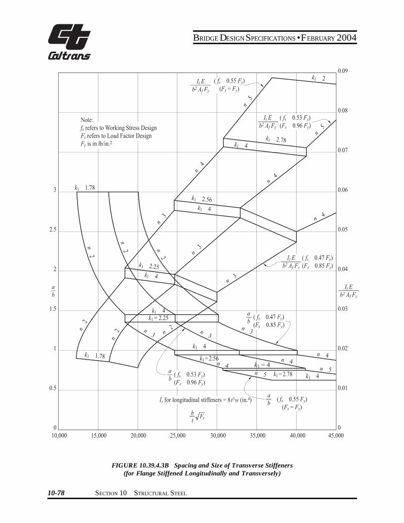
BRIDGE DESIGN SPECIFICATIONS bull FEBRUARY 2004
3
2 5
2
a b
1 5
1
0 5
0
( fs 0 47 Fy) (Fs 0 85 Fy)
b t
Fy
Is for longitudinal stiffeners 8 t3w (in 4)
k1 4 k1 2 25
k1 2 25k1 4
k1 2 5 k1 4
k1 1 78
k1 1 78
k1 2 78k1 4
2
5
5
4
4
4
3
3
3
2
2
2
3
3
4
3
4 4
5 5 k1 4k1 2 78
k1 2 5
k1 4
k1 2
2
2
Note fs refers to Working Stress Design Fs refers to Load Factor Design Fy is in lbin 2
a b
( fs 0 47 Fy) (Fs 0 85 Fy)
a b
( fs 0 55 Fy) (Fs Fy)
a b ( fs 0 53 Fy) (Fs 0 9 Fy)
It b f Fy
It b f Fy
( fs 0 53 Fy) (Fs 0 9 Fy)
It b f Fy
( fs 0 55 Fy) (Fs Fy)
k1 4
0 09
0 08
0 07
0 0
0 05
0 04
It b f Fy
0 03
0 02
0 01
10000 15000 20000 25000 30000 35000 40000 45000
FIGURE 103943B Spacing and Size of Transverse Stiffeners (for Flange Stiffened Longitudinally and Transversely)
10-78 SECTION 10 STRUCTURAL STEEL
0
BRIDGE DESIGN SPECIFICATIONS bull FEBRUARY 2004
103944 Compression Flanges Stiffened Longitudinally and Transversely
1039441 The longitudinal stiffeners shall be at equal spacings across the flange width and shall be proportioned so that the moment of inertia of each stiffshyeners about an axis parallel to the flange and at the base
+ of the stiffeners meet the following requirement
I s ge 8t3 f w (10-80)
1039442 The transverse stiffeners shall be proshyportioned so that the moment of inertia of each stiffener about an axis through the centroid of the section and parallel
+ to its bottom edge meets the following requirement
3 3 fs Af+ It ge 010 (n + 1) w (10-81)E do
where
Af = area of bottom flange including longitudinal + stiffeners (in2) + do = spacing of transverse stiffeners (in)
fs = maximum longitudinal bending stress in the flange of the panels on either side of the transshy
+ verse stiffeners (psi) + E = modulus of elasticity of steel (psi)
+ 1039443 For the flange including stiffeners the + calculated bending stress shall not exceed the allowable + bending stress Fb (psi) determined by either of the + following equations
w 3070 k1+ lefor t Fy
+ Fb = 055 Fy (10-82)
3070 k1 w 6650 k1 le or + lt smaller of 60for Fy t F y
w F 6650 k1 minus y
π t F = 055F minus0224 F 1minussinb y y + 2 3580 k1
(10-83)
6650 k1 wle le 60 +for Fy t
t 2
6Fb = 144 k1 times10 (10-84) + w
where
( ) [ ( ) ( ) 1
1 22
2
1 +
+ =
a bn
a bk ]
( ) [ 1 ]011 873
2
++
+
n (10-85) +
1039444 Deleted +
1039445 Deleted +
1039446 The maximum value of the buckling coefficient k1 shall be 4 When k1 has its maximum value the transverse stiffeners shall have a spacing a equal to or less than 4w If the ratio ab exceeds 3 transverse stiffeners are not necessary
1039447 The transverse stiffeners need not be connected to the flange plate but shall be connected to the webs of the box and to each longitudinal stiffener The connection to the web shall be designed to resist the vertical force determined by the formula
R = FySs
w (10-86)2 b
where
Ss = section modulus of the transverse stiffener (in3) +
SECTION 10 STRUCTURAL STEEL 10-79
BRIDGE DESIGN SPECIFICATIONS bull FEBRUARY 2004
1039448 The connection to each longitudinal stiffener shall be designed to resist the vertical force determined by the formula
F S =Rs n
y
bs
(10-87)
103945 Compression Flange Stiffeners General
+ 1039451 The width-thickness ratio (bts) of any outstanding element of the flange stiffeners shall not
+ exceed the limiting values specified in Table 10345A
1039452 Longitudinal stiffeners shall be exshytended to locations where the maximum stress in the flange does not exceed that allowed for base metal adjacent to or connected by fillet welds
+ 10395 Flange to Web Welds
The total effective thickness of the web-flange welds + shall be not less than the thickness of the web Regardless
of the type weld used welds shall be deposited on both sides of the connecting flange or web plate
10396 Diaphragms
103961 Diaphragms cross-frames or other means shall be provided within the box girders at each support to resist transverse rotation displacement and distortion
103962 Intermediate diaphragms or cross-frames are not required for steel box girder bridges designed in accordance with this specification
10397 Lateral Bracing
Generally no lateral bracing system is required beshytween box girders A horizontal wind load of 50 pounds per square foot shall be applied to the area of the supershystructure exposed in elevation Half of the resulting force shall be applied in the plane of the bottom flange The section assumed to resist the horizontal load shall consist of the bottom flange acting as a web and 12 times the thickness of the webs acting as flanges A lateral bracing system shall be provided if the combined stresses due to the specified horizontal force and dead load of steel and deck exceed 150 percent of the allowable design stress
10398 Access and Drainage
Consistent with climate location and materials considshyeration shall be given to the providing of manholes or other openings either in the deck slab or in the steel box for form removal inspection maintenance drainage etc
1040 HYBRID GIRDERS
10401 General
104011 This section pertains to the design of girders that utilize a lower strength steel in the web than in one or both of the flanges It applies to composite and noncomposite plate girders and composite box girders At any cross section where the bending stress in either flange exceeds 55 percent of minimum specified yield strength of the web steel the compression-flange area shall not be less than the tension-flange area The top-flange area shall include the transformed area of any portion of the slab or reinforcing steel that is considered to act compositely with the steel girder
104012 The provisions of these Specifications shall govern where applicable except as specifically modified by Articles 10401 through 10404
+
10402 Allowable Stresses
104021 Bending
1040211 The bending stress in the web may exceed the allowable stress for the web steel provided that the stress in each flange does not exceed the allowshyable stress from Articles 103 or 1032 for the steel in that flange multiplied by the reduction factor R
( ) ( ) ( ψ )βψ
ψαψαβψ minus+
+minusminusminus=
36 31
1 2
R (10-89)
(See Figures 104021A and 104021B)
where
α = specified minimum yield strength of the web divided by the specified minimum yield strength of the tension flange
β = area of the web divided by the area of the tension flange
Bottom flange of orthotropic deck bridge
+
10-80 SECTION 10 STRUCTURAL STEEL
BRIDGE DESIGN SPECIFICATIONS bull FEBRUARY 2004
103944 Compression Flanges Stiffened Longitudinally and Transversely
1039441 The longitudinal stiffeners shall be at equal spacings across the flange width and shall be proportioned so that the moment of inertia of each stiffshyeners about an axis parallel to the flange and at the base
+ of the stiffeners meet the following requirement
I s ge 8t3 f w (10-80)
1039442 The transverse stiffeners shall be proshyportioned so that the moment of inertia of each stiffener about an axis through the centroid of the section and parallel
+ to its bottom edge meets the following requirement
3 3 fs Af+ It ge 010 (n + 1) w (10-81)E do
where
Af = area of bottom flange including longitudinal + stiffeners (in2) + do = spacing of transverse stiffeners (in)
fs = maximum longitudinal bending stress in the flange of the panels on either side of the transshy
+ verse stiffeners (psi) + E = modulus of elasticity of steel (psi)
+ 1039443 For the flange including stiffeners the + calculated bending stress shall not exceed the allowable + bending stress Fb (psi) determined by either of the + following equations
w 3070 k1+ lefor t Fy
+ Fb = 055 Fy (10-82)
3070 k1 w 6650 k1 le or + lt smaller of 60for Fy t F y
w F 6650 k1 minus y
π t F = 055F minus0224 F 1minussinb y y + 2 3580 k1
(10-83)
6650 k1 wle le 60 +for Fy t
t 2
6Fb = 144 k1 times10 (10-84) + w
where
( ) [ ( ) ( ) 1
1 22
2
1 +
+ =
a bn
a bk ]
( ) [ 1 ]011 873
2
++
+
n (10-85) +
1039444 Deleted +
1039445 Deleted +
1039446 The maximum value of the buckling coefficient k1 shall be 4 When k1 has its maximum value the transverse stiffeners shall have a spacing a equal to or less than 4w If the ratio ab exceeds 3 transverse stiffeners are not necessary
1039447 The transverse stiffeners need not be connected to the flange plate but shall be connected to the webs of the box and to each longitudinal stiffener The connection to the web shall be designed to resist the vertical force determined by the formula
R = FySs
w (10-86)2 b
where
Ss = section modulus of the transverse stiffener (in3) +
SECTION 10 STRUCTURAL STEEL 10-79
BRIDGE DESIGN SPECIFICATIONS bull FEBRUARY 2004
1039448 The connection to each longitudinal stiffener shall be designed to resist the vertical force determined by the formula
F S =Rs n
y
bs
(10-87)
103945 Compression Flange Stiffeners General
+ 1039451 The width-thickness ratio (bts) of any outstanding element of the flange stiffeners shall not
+ exceed the limiting values specified in Table 10345A
1039452 Longitudinal stiffeners shall be exshytended to locations where the maximum stress in the flange does not exceed that allowed for base metal adjacent to or connected by fillet welds
+ 10395 Flange to Web Welds
The total effective thickness of the web-flange welds + shall be not less than the thickness of the web Regardless
of the type weld used welds shall be deposited on both sides of the connecting flange or web plate
10396 Diaphragms
103961 Diaphragms cross-frames or other means shall be provided within the box girders at each support to resist transverse rotation displacement and distortion
103962 Intermediate diaphragms or cross-frames are not required for steel box girder bridges designed in accordance with this specification
10397 Lateral Bracing
Generally no lateral bracing system is required beshytween box girders A horizontal wind load of 50 pounds per square foot shall be applied to the area of the supershystructure exposed in elevation Half of the resulting force shall be applied in the plane of the bottom flange The section assumed to resist the horizontal load shall consist of the bottom flange acting as a web and 12 times the thickness of the webs acting as flanges A lateral bracing system shall be provided if the combined stresses due to the specified horizontal force and dead load of steel and deck exceed 150 percent of the allowable design stress
10398 Access and Drainage
Consistent with climate location and materials considshyeration shall be given to the providing of manholes or other openings either in the deck slab or in the steel box for form removal inspection maintenance drainage etc
1040 HYBRID GIRDERS
10401 General
104011 This section pertains to the design of girders that utilize a lower strength steel in the web than in one or both of the flanges It applies to composite and noncomposite plate girders and composite box girders At any cross section where the bending stress in either flange exceeds 55 percent of minimum specified yield strength of the web steel the compression-flange area shall not be less than the tension-flange area The top-flange area shall include the transformed area of any portion of the slab or reinforcing steel that is considered to act compositely with the steel girder
104012 The provisions of these Specifications shall govern where applicable except as specifically modified by Articles 10401 through 10404
+
10402 Allowable Stresses
104021 Bending
1040211 The bending stress in the web may exceed the allowable stress for the web steel provided that the stress in each flange does not exceed the allowshyable stress from Articles 103 or 1032 for the steel in that flange multiplied by the reduction factor R
( ) ( ) ( ψ )βψ
ψαψαβψ minus+
+minusminusminus=
36 31
1 2
R (10-89)
(See Figures 104021A and 104021B)
where
α = specified minimum yield strength of the web divided by the specified minimum yield strength of the tension flange
β = area of the web divided by the area of the tension flange
Bottom flange of orthotropic deck bridge
+
10-80 SECTION 10 STRUCTURAL STEEL