m arlb o ro u gh & sto ckto n lo g effect sto ve r an ge · m arlb o ro u gh & sto ckto n...
TRANSCRIPT

Marlborough & StocktonLog Effect Stove Range
Conventional FlueWith upgradeable control valve
Instructions for Use,Installation and ServicingFor use in GB, IE (Great Britain and Eire)
PR0842 Issue 2 (February 2007)
IMPORTANTDo not attempt to burn rubbish in this fire. This stove must only be operated with the door secured firmly in position. The outer casing of this stove will become hot whilst in operation, it is therefore recommended that the appliance be
guarded to protect the young and infirm using a suitable guard.Ensure that fabrics such as curtains are not positioned above or near to the stoves outer casing.
Please read these Instructions carefully and keep them in a safe place.They will be needed when servicing the fire.
The commissioning sheet found on page 3 of these instructions should be completed by the installer.
This appliance has been certified for use in countries other than those stated. To install this appliance in these countries, it is essential to obtain thetranslated instructions and in some cases the appliance will require modification. Contact Gazco for further information.
2
CONTENTSCOVERING THE FOLLOWING MODELS
MARLBOROUGH – 8610LUC – P8610LUCSTOCKTON – 8617LUC – P8617LUC
PAGE
APPLIANCE COMMISIONING CHECKLIST 3
USER INSTRUCTIONS 4
INSTALLATION INSTRUCTIONS 8
Technical Specifications 8
Site Requirements 9
Installation 10
Commissioning 14
SERVICING INSTRUCTIONS 15Servicing Requirements 15
Fault Finding 15
How to replace parts 17
Basic spare parts list 21
Service Record 22

3
FLUE CHECK PASS FAIL
1. Flue is correct for appliance
2. Flue flow test
3. Spillage test
GAS CHECK
1. Gas soundness & let by test
2. Standing pressure test mb
3. Appliance working pressure (on High Setting) mb
NB All other gas appliances must be operating on full
4. Gas rate
5. Does ventilation meet appliance requirements
6. Have controls been upgraded (Upgradeable models only) 8455 Standard YES NO
8456 Programmable Time & Temperature YES NO
APPLIANCE COMMISSIONING CHECKLIST
Dealer . . . . . . . . . . . . . . . . . . . . . . . . . . . . . . . . . . . . . . . . . . . . . . . . . . . . . . . . . . . . . . . . . . . . . . .
. . . . . . . . . . . . . . . . . . . . . . . . . . . . . . . . . . . . . . . . . . . . . . . . . . . . . . . . . . . . . . . . . . . . . . . . . . . . . . . .
. . . . . . . . . . . . . . . . . . . . . . . . . . . . . . . . . . . . . . . . . . . . . . . . . . . . . . . . . . . . . . . . . . . . . . . . . . . . . . . .
Contact No. . . . . . . . . . . . . . . . . . . . . . . . . . . . . . . . . . . . . . . . . . . . . . . . . . . . . . . . . . . . . . . .
Date of Purchase. . . . . . . . . . . . . . . . . . . . . . . . . . . . . . . . . . . . . . . . . . . . . . . . . . . . . . . .
Model No. . . . . . . . . . . . . . . . . . . . . . . . . . . . . . . . . . . . . . . . . . . . . . . . . . . . . . . . . . . . . . . . . .
Serial No. . . . . . . . . . . . . . . . . . . . . . . . . . . . . . . . . . . . . . . . . . . . . . . . . . . . . . . . . . . . . . . . . . .
Gas Type . . . . . . . . . . . . . . . . . . . . . . . . . . . . . . . . . . . . . . . . . . . . . . . . . . . . . . . . . . . . . . . . . . .
Installation Company. . . . . . . . . . . . . . . . . . . . . . . . . . . . . . . . . . . . . . . . . . . . . . . . . .
. . . . . . . . . . . . . . . . . . . . . . . . . . . . . . . . . . . . . . . . . . . . . . . . . . . . . . . . . . . . . . . . . . . . . . . . . . . . . . . . .
. . . . . . . . . . . . . . . . . . . . . . . . . . . . . . . . . . . . . . . . . . . . . . . . . . . . . . . . . . . . . . . . . . . . . . . . . . . . . . . . .
Engineer . . . . . . . . . . . . . . . . . . . . . . . . . . . . . . . . . . . . . . . . . . . . . . . . . . . . . . . . . . . . . . . . . . . .
Contact No.. . . . . . . . . . . . . . . . . . . . . . . . . . . . . . . . . . . . . . . . . . . . . . . . . . . . . . . . . . . . . . . .
Corgi Reg No.. . . . . . . . . . . . . . . . . . . . . . . . . . . . . . . . . . . . . . . . . . . . . . . . . . . . . . . . . . . . .
Date of Installation . . . . . . . . . . . . . . . . . . . . . . . . . . . . . . . . . . . . . . . . . . . . . . . . . . . . .
IMPORTANT NOTICEExplain the operation of the appliance to the end user, hand the completed instructions to them for safe keeping,
as the information will be required when making any guaranteed claims.
DEALER AND INSTALLER INFORMATION
This product is guaranteed for 2 years from the date of installation, as set out in the terms and conditions of sale between Gazco and yourlocal Gazco dealer. This guarantee will be invalid, to the extent permitted by law, if the above Appliance Commissioning Checklistis not fully completed by the installer and available for inspection by a Gazco engineer. The guarantee will only be valid during thesecond year, to the extent permitted by law, if the annual service recommended in the Instructions for Use has been completed by aCorgi registered engineer, and a copy of the service visit report is available for inspection by a Gazco engineer.
4
USER INSTRUCTIONS
1. GENERAL
1.1 Installation and servicing must be carried out by acompetent person in accordance with Gas Safety (Installationand Use) Regulations 1998, the relevant British Standards forInstallation, appropriate Codes of Practice and in accordancewith the manufacturer’s instructions. It is recommended thata CORGI registered engineer be used for this purpose asthey are approved by the HSE under the above regulations.
1.2 This appliance is suitable for use in G.B. and I.E. usingNatural Gas at a supply pressure of 20mbar or LPG at asupply pressure of 29mbar (Butane) or 37mbar (Propane).
1.3 The installation shall also be completed in accordance with:The Building Regulations issued by The Department of TheEnvironment.The Building Standards (Scotland) Regulations issued by theScottish Development Department. For Republic of Ireland,reference should be made to the relevant standardsgoverning installations (IS813:1996)
1.4 Read all these Instructions before commencing installation.1.5 This appliance must be installed in accordance with the rules
in force and only used in a sufficiently ventilated space.1.6 Ensure that curtains are not positioned above the stove, and
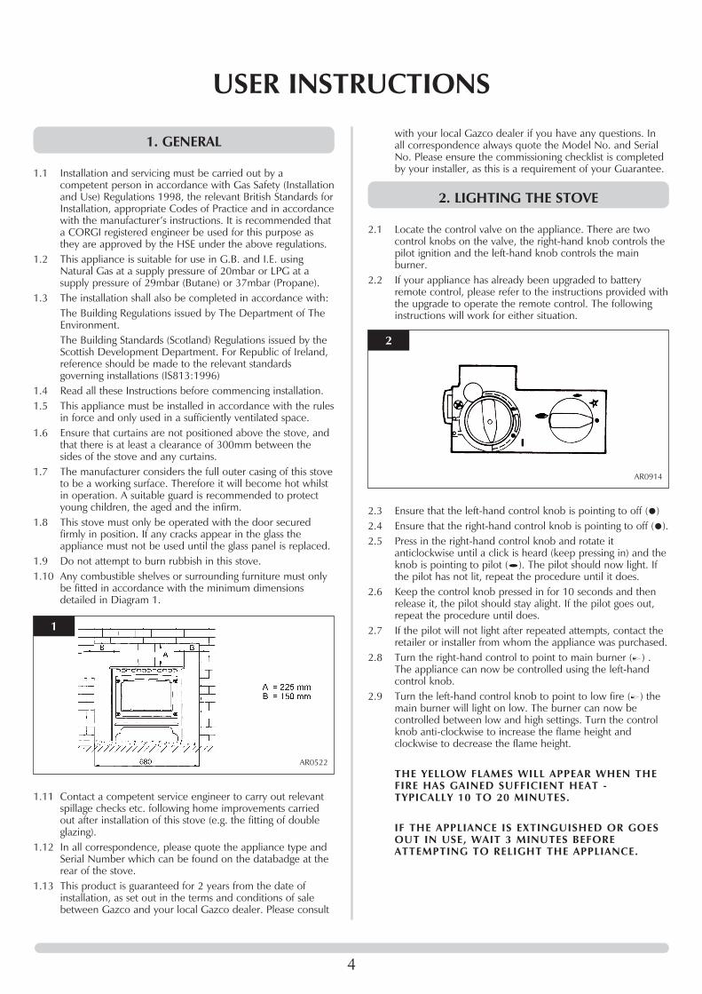
that there is at least a clearance of 300mm between thesides of the stove and any curtains.
1.7 The manufacturer considers the full outer casing of this stoveto be a working surface. Therefore it will become hot whilstin operation. A suitable guard is recommended to protectyoung children, the aged and the infirm.
1.8 This stove must only be operated with the door securedfirmly in position. If any cracks appear in the glass theappliance must not be used until the glass panel is replaced.
1.9 Do not attempt to burn rubbish in this stove.1.10 Any combustible shelves or surrounding furniture must only
be fitted in accordance with the minimum dimensionsdetailed in Diagram 1.
1.11 Contact a competent service engineer to carry out relevantspillage checks etc. following home improvements carriedout after installation of this stove (e.g. the fitting of doubleglazing).
1.12 In all correspondence, please quote the appliance type andSerial Number which can be found on the databadge at therear of the stove.
1.13 This product is guaranteed for 2 years from the date ofinstallation, as set out in the terms and conditions of salebetween Gazco and your local Gazco dealer. Please consult
with your local Gazco dealer if you have any questions. Inall correspondence always quote the Model No. and SerialNo. Please ensure the commissioning checklist is completedby your installer, as this is a requirement of your Guarantee.
2. LIGHTING THE STOVE
2.1 Locate the control valve on the appliance. There are twocontrol knobs on the valve, the right-hand knob controls thepilot ignition and the left-hand knob controls the mainburner.
2.2 If your appliance has already been upgraded to batteryremote control, please refer to the instructions provided withthe upgrade to operate the remote control. The followinginstructions will work for either situation.
2.3 Ensure that the left-hand control knob is pointing to off ( ) 2.4 Ensure that the right-hand control knob is pointing to off ( ).2.5 Press in the right-hand control knob and rotate it
anticlockwise until a click is heard (keep pressing in) and theknob is pointing to pilot ( ). The pilot should now light. Ifthe pilot has not lit, repeat the procedure until it does.
2.6 Keep the control knob pressed in for 10 seconds and thenrelease it, the pilot should stay alight. If the pilot goes out,repeat the procedure until does.
2.7 If the pilot will not light after repeated attempts, contact theretailer or installer from whom the appliance was purchased.
2.8 Turn the right-hand control to point to main burner ( ) .The appliance can now be controlled using the left-handcontrol knob.
2.9 Turn the left-hand control knob to point to low fire ( ) themain burner will light on low. The burner can now becontrolled between low and high settings. Turn the controlknob anti-clockwise to increase the flame height andclockwise to decrease the flame height.
THE YELLOW FLAMES WILL APPEAR WHEN THEFIRE HAS GAINED SUFFICIENT HEAT -TYPICALLY 10 TO 20 MINUTES.
IF THE APPLIANCE IS EXTINGUISHED OR GOESOUT IN USE, WAIT 3 MINUTES BEFOREATTEMPTING TO RELIGHT THE APPLIANCE.
1
AR0522
2
AR0914

6. CLEANING THE FIRE
WARNING: DO NOT ATTEMPT TO CLEAN THESTOVE UNTIL IN A COLD CONDITION. THESTOVE RETAINS ITS HEAT FOR A CONSIDERABLETIME AFTER SHUTDOWN.
NOTE: THE CAST IRON DOOR IS HEAVY, TAKEEXTREME CARE WHEN HANDLING.
6.1 Remove the door by undoing the four dome nuts using thetool supplied and place to one side.
6.2 Carefully remove the ceramic fuel bed components andplace to one side taking care to protect floor coverings etc.PLEASE HANDLE WITH CARE.
6.3 The logs should not require cleaning. Do not use a vacuumcleaner or brush to clean the logs. Any large pieces of debrismay be removed by hand.
6.4 Ensure any debris is removed from the burner ports.6.5 Replace the ceramics and door referring to Section 7 below.6.7 Use a damp cloth to clean the outer casing of the
appliance.
7. FUEL BED ARRANGEMENTS
Remove the cast iron door using the tool provided. Removethe front coal retainer by lifting vertically.NOTE: THE CAST IRON DOOR IS HEAVY, TAKE EXTREMECARE WHEN HANDLING TO AVOID DAMAGING THEOUTER CASING.The fuel bed consists of 5 logs and 2 ash panels. The logshave letters A,B,C,D and E moulded into them foridentification.
7.1 Take the rear log A and place it up against the rear of thefire sitting on the two flat ledges of the burner. The two legsof the log should sit between the rear burner ports. Seediagram 3. Ensure there is an equal gap between each sideof the log and the side of the firebox.
5
3. TURNING OFF THE STOVE
3.1 To turn the stove off, locate the control valve, turn the left-hand control knob until it points to off ( ). The main burnerwill go out leaving the pilot burning.
3.2 To turn the pilot off, locate the control valve, turn the right-hand control knob until it points to off ( ), the pilot will goout.
4. UPGRADING YOUR STOVE
4.1 Your stove is fitted with a control valve that can be easilyupgraded to battery powered remote control. This upgradecan be fitted by anyone capable of simple DIY jobs andrequires no special training. There are two versions of thiscontrol which can be obtained through your local Gazcostockist.
4.2 STANDARD REMOTE CONTROL This remote control cancontrol the gas appliance after the pilot has been lit. It canturn the main burner on and regulate it from low through tohigh and back again. It can turn the main burner off leavingthe pilot burning. GAZCO PART NUMBER 8455.
4.3 THERMOSTATIC AND TIMER REMOTE CONTROL Thisremote control can control the gas appliance after the pilothas been lit. In ‘MANUAL MODE’ it can be used to turn themain burner on and manually regulate it from low throughto high and back again. It can also be used to turn the mainburner off leaving the pilot burning. In ‘AUTO MODE’ it willautomatically regulate the room temperature. In ‘TIMERMODE’ it will turn the fire on and off according to a pre-setprogramme and automatically regulate the roomtemperature during two ON periods. GAZCO PARTNUMBER 8456.
5. HANDLING & DISPOSAL OF FIRE CERAMICS
The fuel effect and side panels in this appliance are madefrom Refractory Ceramic Fibre (RCF), a material which iscommonly used for this application.Protective clothing is not required when handling thesearticles, but we recommend you follow normal hygiene rulesof not smoking, eating or drinking in the work area andalways wash your hands before eating or drinking. To ensure that the release of RCF fibres are kept to aminimum, during installation and servicing a HEPA filteredvacuum is recommended to remove any dust accumulatedin and around the appliance before and after working on it.When servicing the appliance it is recommended that thereplaced items are not broken up, but are sealed withinheavy duty polythene bags and labelled as RCF waste.RCF waste is classed as stable, non-reactive hazardous wasteand may be disposed of at a licensed landfill site.Excessive exposure to these materials may cause temporaryirritation to eyes, skin and respiratory tract; wash handsthoroughly after handling the material.
USER INSTRUCTIONS
3
AR1610

6
7.2 Place log B on the left-hand side of the burner with thelocation bar on the underside of the log fully located in thelong slot of the burner. Make sure the log is as far to the leftas possible. See diagram 4.
7.3 Place log C on the right-hand side of the burner with thelocation bar on the underside of the log fully located in thelong slot in the burner. Make sure the log is as far right aspossible. See diagram 5.
7.4 Place log D across from the rear log A to log B on the left-hand side. There are cut-outs in both logs for location. Seediagram 6.
7.5 There are two ash panels which lay across the front of theburner skin. Place the panel with the flat edge facing the leftside of the firebox. There are location holes on this logwhich fit over the screw holes of the burner skin.
7.6 Place the second ash panel to the right of the first, with thepointed end of the panel fitting into the V shape. This panelshould locate on the screw holes of the burner skin. Ensurethat both logs are horizontal to the burner ports.
7.7 Place log E across from the rear of log A to log C on theright-hand side. Again, there are cut-outs for location. Thefront of the log should sit on the front ash panels and shouldfit tight to log C. See diagram 9.
USER INSTRUCTIONS
4
AR1611
5
AR1612
6
AR1613
7
AR1614
8
AR1615
9
AR1616

7.8 Carefully insert the front coal retainer into the front panel ofthe firebox. Take care not the scrape/damage the logs. Thiscoal retainer sits in two brackets. Ensure it is fully inserted,leaving approximately a 4 mm gap between the fireboxledge and the bottom of the coal retainer.
7.9 Ensure that the fibreglass seal on the back of the door isintact, locate the door on the four studs and slide back tothe firebox. Secure in place using the four dome nuts andtool supplied. Do not overtigthen the nuts, see diagram 11.
NEVER OPERATE THE STOVE WHEN THE DOORIS REMOVED.
8. GAZCO FLUE SURE SYSTEM
8.1 The stove is fitted with the Gazco Flue Sure System, whichwill act to cut off the gas supply to the burners in the eventof incorrect operation of the flue. If the system acts to cut offthe gas supply, this indicates that there is insufficient fluepull. If this occurs a minimum of 10 minutes should beallowed before trying to relight. Continued operation of thissafety device means there may be a serious problem withthe flue system. A qualified gas engineer should inspect this.DO NOT USE THE STOVE UNTIL AN ENGINEERSAYS IT IS SAFE TO DO SO.
9. THE FLAME FAILURE DEVICE
9.1 This is a safety feature incorporated in all GAZCO fireswhich automatically switches off the gas supply if the pilotlight goes out and fails to heat the thermocouple.
10. ‘RUNNING IN’
10.1 The surface coating on your GAZCO fires will "burn off"during the first 24 hours of use, producing a harmless andtemporary odour. This will disappear after the short periodof use. If the odour persists, ask your retailer for advice.
11. SERVICING
11.1 A qualified gas engineer must service the stove every 12months. In all correspondence, always quote the appliancetype and the Serial Number that may be found on thedatabadge on the appliance.
12. VENTILATION
12.1 Any purpose provided ventilation should be checkedperiodically to ensure that it is free from obstruction.
13. INSTALLATION DETAILS
13.1 To assist in any future correspondence, your installer shouldhave completed the commissioning sheet at the front of thismanual. This records the essential installation details of thisappliance. In all correspondence always quote the ModelNo. and Serial No.
14. HOT SURFACES
14.1 The manufacturer consider the full outer casing of this stoveto be a working surface. Therefore it will become hot whilstin operation. A suitable guard is recommended to protectyoung children, the aged and the infirm.
7
USER INSTRUCTIONS
10
AR1617
11
AR0390

8
INSTALLATION INSTRUCTIONSTECHNICAL SPECIFICATION
COVERING THE FOLLOWING MODELS:MARLBOROUGH – 8610LUC – P8610LUC
STOCKTON – 8617LUC – P8617LUC
Model Gas Gas Working NOX Aeration Injector Gas Rate Input kW (Gross) Country
CAT. Type Pressure Class m3/h High Low
Marlborough 8610LUC I2H Natural 20 mbar 3 Ø 14.5 375 0.623 6.6 3.6 GB, IE(G20) Gross Gross
Marlborough P8610LUC I3P Propane 37 mbar 3 Ø 11.5 x 2 165 0.232 6.4 3.6 GB, IE(G31) Gross Gross
Stockton – 8617LUC I2H Natural 20mbar 3 Ø 14.5 375 0.623 6.6 3.6 GB, IE
(G20) Gross Gross
Stockton – P8617LUC I3P Propane 37mbar 3 Ø 11.5 x 2 165 0.232 6.4 3.6 GB, IE
(G31) Gross Gross
Packing ChecklistQty Description
1 Stove
1 Flue Blanking plate
1 Coal Retainer
1 Log set (5 logs)*
2 Ash Panels* (2 sections)*
1 Fixing Kit Containing
1 Instruction Manual
1 Wood Screw
1 Rawplug
1 Box spanner
*Packed in appliance
1
AR1623
Efficiency Class II
Flue Outlet Size 127mm (5”) Ø
Gas Inlet Connection Size 8mm Ø
Minimum Flue Specification T260 / N2 / 0 / D / 1
Maximum Flue Temperature 180°C
9
INSTALLATION INSTRUCTIONSSITE REQUIREMENTS
1. FLUE AND CHIMNEY REQUIREMENTS
1.1 The chimney or flue system must comply with the rules inforce and must be a minimum of 127mm in diameter. (5").
1.2 The minimum effect height of the flue or chimney must be 3metres (10ft). Any horizontal flue run from the rear outletshould not exceed 100mm from the back of the appliance.
1.3 The chimney or flue must be free from any obstruction. Anydamper plates should be removed or secured in the fullyopen position and no restrictor plates should be fitted.
1.4 The chimney should be swept prior to the installation of theappliance. However, where it can be seen that the chimneyis clean and unobstructed throughout its entire length, itneed not be swept.NOTE: If it is intended to fit the stove into a existing brickbuilt chimney without a closure plate, a 5" (127mm) linermust be used. Larger lined flues may work, but in someinstances could cause cold start flue problems resulting innuisance shutdown. Lined flues above 7" (175mm) are notrecommended.Due to recent changes to European chimney standards, newflues and chimneys are now described by their temperature,pressure and resistance to corrosion, condensation and fire.To assist in identifying the correct flue system, the minimumflue specification is shown in the technical specification ofthis book. Existing chimneys are not covered by this system.* Closure Plate InstallationThis appliance can be installed into a standard fireplaceopening with the optional closure plate and spigot extensionmade for the appliance. Note the stove and plate willrequire removing, when carrying out the annual service.(Not suitable for precast letterbox flues).
2. VENTILATION
2.1 Consult the rules in force. Note: This appliance does not normally require anyadditional ventilation when installed in G.B.
3. INSTALLATION OF THE GAS SUPPLY
3.1 Before installation, ensure that the local distributionconditions (identification of the type of gas and pressure)and the adjustment of the appliance are compatible.
3.2 Ensure that the gas supply is capable of delivering therequired amount of gas and is in accordance with the rulesin force.
3.3 Soft copper tubing and soft soldered joints can be used butmust not be closer than 50mm to the base of the tray.
3.4 A means of isolating the gas supply to the appliance must beprovided independent of any appliance control.
3.5 All supply gas pipes must be purged of any debris that mayhave entered prior to connection to the appliance.
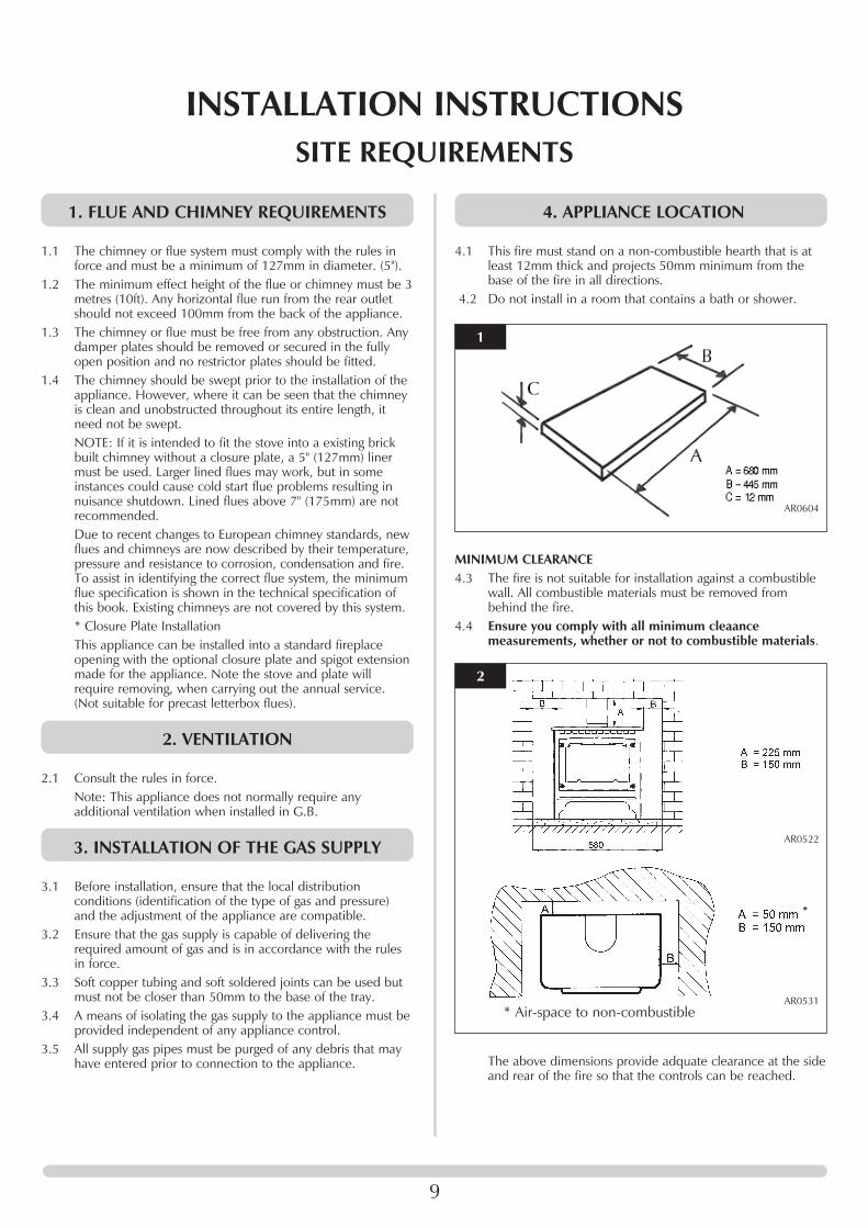
4. APPLIANCE LOCATION
4.1 This fire must stand on a non-combustible hearth that is atleast 12mm thick and projects 50mm minimum from thebase of the fire in all directions.
4.2 Do not install in a room that contains a bath or shower.
MINIMUM CLEARANCE4.3 The fire is not suitable for installation against a combustible
wall. All combustible materials must be removed frombehind the fire.
4.4 Ensure you comply with all minimum cleaancemeasurements, whether or not to combustible materials.
The above dimensions provide adquate clearance at the sideand rear of the fire so that the controls can be reached.
1
AR0604
2
AR0522
AR0531
*
* Air-space to non-combustible

10
IMPORTANT: ENSURE THAT THE APPLIANCE ISCORRECTLY ADJUSTED FOR THE GAS TYPE ANDCATEGORY APPLICABLE IN THE COUNTRY OFUSE. REFER TO DATABADGE AND TECHNICALSPECIFICATIONS OF THIS BOOKLET. FORDETAILS OF CHANGING BETWEEN GAS TYPESREFER TO SECTION 11, REPLACING PARTS.
1. CONTROL UPGRADE
1.1 This stove is fitted with a control valve that can be easilyupgraded to battery powered remote control. There are twoversions of this control which can be obtained through yourlocal Gazco stockist.
1.2 This upgrade can be fitted before or after installation but ifside clearances are limited then it will be easier to upgradethe stove before installation. Full instructions are includedwith the kit.
1.3 STANDARD REMOTE CONTROL This remote control can control the gas appliance after thepilot has been lit. It can turn the main burner on andregulate it from low through to high and back again. It canturn the main burner off leaving the pilot burning. GAZCOPART NUMBER 8455.
1.4 THERMOSTATIC AND TIMER REMOTE CONTROL This remote control can control the gas appliance after thepilot has been lit. In "MANUAL MODE" it can be used toturn the main burner on and manually regulate it from lowthrough to high and back again. It can also be used to turnthe main burner off leaving the pilot burning. In "AUTOMODE" it will automatically regulate the room temperature.In "TIMER MODE" it will turn the fire on and off accordingto a pre-set programme and automatically regulate the roomtemperature during two on periods. GAZCO PART NUMBER8456.
2. SAFETY PRECAUTIONS
2.1 This appliance must be installed in accordance with the rulesin force, and used only in a sufficiently ventilated space.Place read these instructions before installation and use ofthis appliance.
2.2 All the instructions must be left intact with the user.2.3 In your own interests and those of safety, this appliance must
be installed by a competent person in accordancewith local and national codes of practice. Failure to installthe appliance correctly could lead to prosecution.
2.4 This appliance is intended for use on a governed gasinstallation and set to the required pressure.
2.5 Keep all plastic bags away from young children.2.6 Do not place any object on or near to the stove. Allow
adequate clearance above the stove. See diagram 2 SiteRequirements, Appliance Location.
2.7 The stove is fitted with the Gazco Flue Sure System, whichwill act to cut off the gas supply to the appliance in theevent of incorrect operation of the flue. If the system acts toshut off the gas supply, this indicates that there is insufficientflue pull. If this occurs a minimum of 10 minutes should be
allowed before trying to relight. Continued operation of thissafety device means that there may be a serious problemwith the flue system; a qualified gas engineer should inspectthis. DO NOT USE THE STOVE UNTIL AN ENGINEER SAYSIT IS SAFE TO DO SO.
2.8 The Flue Sure System must not be tampered with. Use onlygenuine Gazco replacement parts when servicing the system- refer to Servicing section, Replacing Parts.
3. INSTALLATION OF THE STOVE
FLUE PIPE INSTALLATION3.1 Open the carton and remove accessory carton and stove
unit. It will now be necessary to decide upon top or rear flueexit, the stove is factory built for rear flue exit, but it may bechanged to top exit by using the following method.
3.1.1 Remove the flue spigot from the rear of the stove andreplace with the blanking plate from the top of the stove andvice versa.
3.2 Position the stove ensuring all appropriate clearances areobserved. Using a pencil, mark the position of the holes inthe fixing brackets attached to the inside of the rear legs.
3.3 Remove the stove and drill the holes using a number 12masonry drill. Push rawlplugs into the holes and insert thewoodscrews until the head is approximately 3mm proud ofthe hearth. Place the stove in position over the bracket sothat the screw heads locate in the large part of the slot. Pushthe stove back so that the screw heads engage fully into thenarrow part of the slot, tighten the screws if desired.
3.4 Having run the gas supply to the stove, PURGE THE SUPPLYPIPE, this is essential to expel any debris that may block thegas controls. Connect the gas supply to the 8mmcompression elbow at the right-hand rear corner of thestove. There is a cutout in the right-hand rear leg to enable adirect straight connection to be made to the rear of thestove. See diagram 1. A gas soundness check must becompleted up to the gas inlet connection.
3.5 Check the pull of the flue system by applying a lightedsmoke pellet to the flue system opening. If there is a definiteflow into the chimney, proceed with the installation. If not,warm the chimney for a few minutes.IF THERE IS STILL NO DEFINITE FLOW, THEFLUE MAY REQUIRE ATTENTION - SEEK EXPERTADVICE
INSTALLATION INSTRUCTIONSINSTALLATION
1
AR0934

in and around the appliance before and after working on it.When servicing the appliance it is recommended that thereplaced items are not broken up, but are sealed withinheavy duty polythene bags and labelled as RCF waste.RCF waste is classed as stable, non-reactive hazardous wasteand may be disposed of at a licensed landfill site.Excessive exposure to these materials may cause temporaryirritation to eyes, skin and respiratory tract; wash handsthoroughly after handling the material.
5. FUELBED ARRANGEMENTS
Remove the cast iron door using the tool provided. Themain ceramic components are inside the firebox.NOTE: THE CAST IRON DOOR IS HEAVY, TAKEEXTREME CARE WHEN HANDLING TO AVOIDDAMAGING THE OUTER CASING.The fuel bed consists of 5 logs and 2 ash panels. The logshave letters A,B,C,D and E moulded into them foridentification.
5.1 Take the rear log A and place it up against the rear of thefire sitting on the two flat ledges of the burner. The two legsof the log should sit between the rear burner ports. Seediagram 3. Ensure an equal gap between each side of thelog and the side of the firebox.
5.2 Place log B on the left-hand side of the burner with thelocation bar on the underside of the log fully located in thelong slot of the burner. Make sure the log is as far to the leftas possible. See diagram 4.
11
3.6 The flue system may now be connected to the stove. Ensurethat all joints are sealed with a suitable fire resistant sealant.It is also recommended that a physical retention method beused at the flue spigot joint, self-tapping screws beingfavoured.
3.7 Connect a suitable pressure gauge to the test point locatedon the inlet fitting, and turn the gas supply on. Light theappliance and check all gas joints for gas soundness. Turnthe appliance to maximum and check that the supplypressure is as stated on the databadge. Turn the gas off andreplace the test point screw. Turn the gas on and check thetest point for gas soundness.
CLOSURE PLATE INSTALLATIONNOTE: The stove is also suitable for installation onto a fireplace
opening. The following method illustrates how this can beachieved with the aid of the optional closure plate andspigot extension. Ensure the fireplace dimensions are asshown in diagram 2.
3.8 Place the closure plate against the fireplace opening andensure that there is sufficient overlap around the perimeterto allow a fume tight seal to be made. Cut straight across thetop of the plate if trimming is required.
3.9 Seal the plate to the opening and the hearth with a suitableheat resisting material. Ensure that any relief opening at thebottom of the plate is left unobstructed.
3.10 Secure the spigot extension to the engine assembly and sealwith heat resisting tape or similar. Position the engineassembly ensuring that the 50mm rear clearance ismaintained, then proceed with the installation as detailed inpoints 3.2 to 3.7 above. See diagram 2.
4. HANDLING & DISPOSAL OF FIRE CERAMICS
The fuel effect and side panels in this appliance are madefrom Refractory Ceramic Fibre (RCF), a material which iscommonly used for this application.Protective clothing is not required when handling thesearticles, but we recommend you follow normal hygiene rulesof not smoking, eating or drinking in the work area andalways wash your hands before eating or drinking. To ensure that the release of RCF fibres are kept to aminimum, during installation and servicing a HEPA filteredvacuum is recommended to remove any dust accumulated
INSTALLATION INSTRUCTIONSINSTALLATION
2
AR0377
3
AR1610
4
AR1611
12
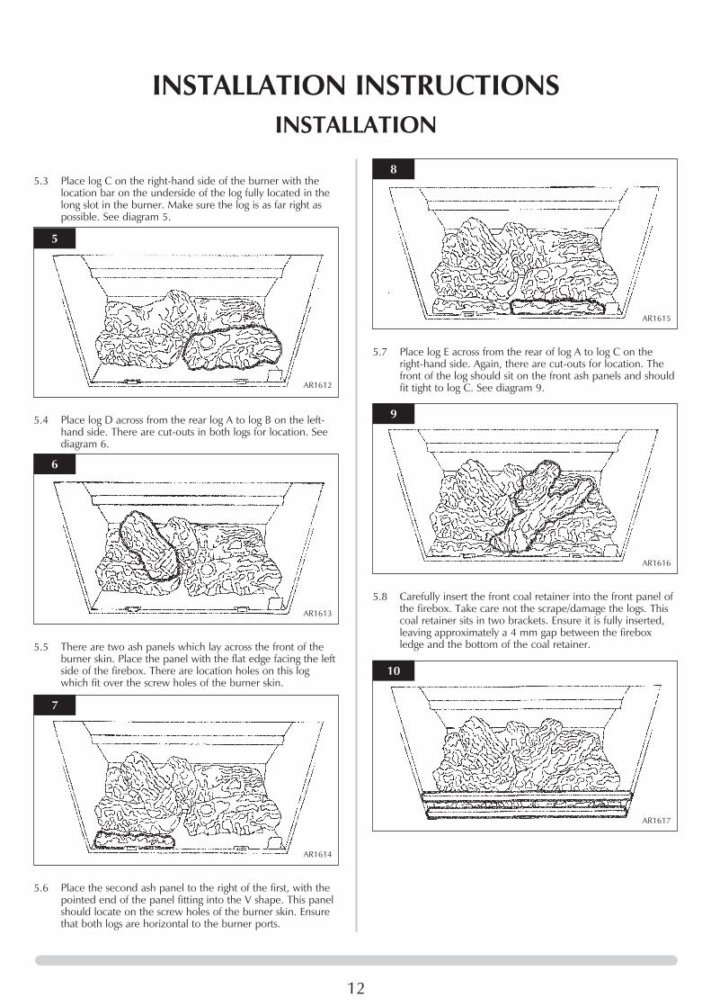
5.3 Place log C on the right-hand side of the burner with thelocation bar on the underside of the log fully located in thelong slot in the burner. Make sure the log is as far right aspossible. See diagram 5.
5.4 Place log D across from the rear log A to log B on the left-hand side. There are cut-outs in both logs for location. Seediagram 6.
5.5 There are two ash panels which lay across the front of theburner skin. Place the panel with the flat edge facing the leftside of the firebox. There are location holes on this logwhich fit over the screw holes of the burner skin.
5.6 Place the second ash panel to the right of the first, with thepointed end of the panel fitting into the V shape. This panelshould locate on the screw holes of the burner skin. Ensurethat both logs are horizontal to the burner ports.
INSTALLATION INSTRUCTIONSINSTALLATION
5.7 Place log E across from the rear of log A to log C on theright-hand side. Again, there are cut-outs for location. Thefront of the log should sit on the front ash panels and shouldfit tight to log C. See diagram 9.
5.8 Carefully insert the front coal retainer into the front panel ofthe firebox. Take care not the scrape/damage the logs. Thiscoal retainer sits in two brackets. Ensure it is fully inserted,leaving approximately a 4 mm gap between the fireboxledge and the bottom of the coal retainer.
5
AR1612
6
AR1613
7
AR1614
8
AR1615
9
AR1616
10
AR1617

13
5.9 Ensure that the fibreglass seal on the back of the door isintact, locate the door on the four studs and slide back tothe firebox. Secure in place using the four dome nuts andtool supplied, do not overtigthen the nuts, see diagram 11.
NEVER OPERATE THE STOVE WHEN THE DOORIS REMOVED OR WHEN THE GLASS IS BROKEN.
6. LIGHTING
6.1 Full instructions are given in the User section under Lightingthe Stove.
INSTALLATION INSTRUCTIONSINSTALLATION
11
AR0390

1. COMMISSIONING
1.1 Close all openable doors and windows in the room, ignitethe stove and operate on maximum for 10 minutes. Removethe plastic sight plug from the right-hand side of the stove.Position a lighted smoke match just inside the draughtdiverter opening and check that all smoke is drawn into theopening by viewing through the sight hole. See diagram 1. Ifthere is any doubt, run the stove for a further 10 minutesand repeat the test.
1.2 If there are any extractor fans in adjacent rooms, the testmust be repeated with the fans running on maximum andinterconnecting doors open.IF SPILLAGE PERSISTS, DISCONNECT THEAPPLIANCE AND SEEK EXPERT ADVICE.For future reference record the installation details on thecommissioning sheet at the end of the User Section of theseinstructions.
14
INSTALLATION INSTRUCTIONSCOMMISSIONING
AR1493
1

15
1. SERVICING REQUIREMENTS
This appliance must be serviced at least once a year by acompetent person.All tests must be serviced by best practice as described bythe current CORGI recommendations.
1.1 Before any tests are undertaken on the appliance, conduct agas soundness test for the property to ensure that there areno gas leaks prior to starting work.
1.2 Before any tests are undertaken on the appliance it is alsorecommended to fully check the operation of the appliance
1.3 Special checks1.3.1 Clean any lint or fluff from the pilot1.3.2 Clean away any fluff or lint from under the
burner1.3.3 Check that the spark gap on the pilot is
correct1.3.4 Check all of the screws which secure the burner skins
and tighten if they are loose.
1.4 Correct any faults found during the initial tests and thenrecommission the appliance conducting the usual safetychecks.
1.5 Advise the customer of any remedial action taken.
SERVICING INSTRUCTIONSSERVICING / FAULT FINDING CHARTS
AR0620
1
PILO
TW
ILL
NO
TLI
GH
T
Ensu
re th
ere
is no
deb
ris a
roun
d th
e pi
lot a
ssem
bly,
(e.g
. soo
t, et
c.) w
hich
cou
ld s
hort
the
spar
k.
Cle
an th
e ar
ea.
Ope
rate
the
valv
e. Is
ther
e a
spar
k?YE
SN
OYE
S
NO
NO
YES
NO
YES
YES
NO
NO
NO
YES
YES
Doe
s th
e pi
lot l
ight
?
Con
sult
Use
r In
stru
ctio
ns a
nd r
etry
.Is
the
cont
rol b
eing
ope
rate
dco
rrec
tly?
Che
ck is
olat
ion
tap
and
gas
met
er.
Retry
.Is
the
gas
turn
ed o
n to
the
appl
ianc
e?
Cor
rect
and
ret
ry.
Is th
e ga
s pr
essu
re c
orre
ct?
Purg
e th
e ga
s pi
pes
and
retry
.H
as th
e sy
stem
got
any
air
in it
?
GO
TO
TH
E N
EXT
CH
ARG
EIG
NIT
ION
FU
NC
TIO
NAL
CH
ECK
2SY
STEM
OK
Ther
e is
a bl
ock
in th
e sy
stem
. Che
ck th
e in
let t
est p
oint
and
the
mag
sea
ting.
Che
ck a
lignm
ent o
f pilo
t bur
ner
head
. Cha
nge
the
igni
tion
lead
. See
Repl
acin
g Pa
rts, S
ectio
n 2.
Will
the
pilo
t lig
ht w
ith a
mat
ch?
IGN
ITIO
N F
UN
CTI
ON
AL C
HEC
K 1

16
SERVICING INSTRUCTIONSSERVICING / FAULT FINDING CHARTS
NO
SPAR
K
IGN
ITIO
N F
UN
CTI
ON
AL C
HEC
K 2
Ensu
re th
ere
is no
deb
ris a
roun
d th
e pi
lot a
ssem
bly,
(e.g
. coa
l, so
otet
c.) w
hich
cou
ld s
hort
the
spar
k, c
lear
the
area
.
From
Igni
tion
Faul
t Fin
ding
Cha
rt Pa
rt 1.
Con
sult
the
Use
rs In
stru
ctio
ns,
retry
.
Ope
rate
the
valv
e to
ligh
t the
pilo
t, do
es th
e va
lve
‘clic
k’?
Is th
e va
lve
bein
g op
erat
edpr
oper
ly?
Is th
e pi
lot b
urne
r ho
rizon
tal?
See
diag
ram
1 o
n pa
ge 1
5.Re
set t
he e
lect
rode
gap
, ret
ry.
Repl
ace
the
pilo
t uni
t.Re
plac
e th
e el
ectro
de le
adan
d re
try.
Rem
ove
the
elec
trode
lead
from
ele
ctro
de w
ith in
sula
ted
plie
rs. H
old
the
tip 4
mm
from
the
pilo
t pip
ewor
k, is
ther
e a
spar
k w
hen
the
valv
e ‘c
licks
’?
Che
ck th
e de
fect
ive
orda
mag
ed c
ontro
l kno
b sp
indl
eor
cam
ope
ratio
n. C
heck
for
corr
ect l
ocat
ion
of p
iezo
com
pone
nts.
Cor
rect
and
retry
.
Is th
e el
ectro
de w
ire d
etac
hed
from
the
piez
o in
the
valv
e?
Repl
ace
the
com
bine
d le
ad,
retry
.
Rem
ove
the
elec
trode
lead
from
the
piez
o. O
pera
te th
eva
lve.
Doe
s a
spar
k ju
mp
from
the
piez
o to
the
valv
e bo
dy?
Has
igni
tion
lead
bec
ome
deta
ched
or
is co
nnec
tion
poor
?
Cor
rect
and
ret
ry.
NO
NO
YES
NO
NO
NO
NO
NO
NO
NO
NO
NO
NO NO
YES
YES
YES
YES
YES
YES
YES
YES
YES
YES
YES
YES
YES
PILO
T W
ILL
NO
T ST
AY L
IT O
R FI
RE G
OES
OU
T IN
USE
SYST
EMO
K
FLAM
EFA
ILU
REFU
NC
TIO
NAL
CH
ECK
3
Ensu
re th
ere
is no
deb
ris a
roun
d th
e pi
lot a
ssem
bly,
(e.g
. coa
l, so
otet
c.) w
hich
cou
ld s
hort
the
spar
k, c
lear
the
area
.
Ligh
t the
pilo
t and
kee
p th
e co
ntro
l kno
b pu
shed
in a
t lea
st 1
0se
cond
s be
fore
letti
ng g
o.
With
the
pilo
tru
nnin
g, is
the
gas
pres
sure
sta
ted
onth
e da
taba
dge?
With
the
fire
runn
ing
on fu
ll, is
the
gas
at th
epr
essu
re s
tate
d on
the
data
badg
e?
Run
for
no m
ore
than
60
seco
nds,
turn
off,
tim
ein
terv
al u
ntil
mag
unit
shut
s w
ith a
clic
k. Is
this
grea
ter
than
7 s
econ
ds?
Tigh
ten
the
conn
ectio
n an
dre
try.
Run
for
60 s
econ
ds,
turn
off,
tim
ein
terv
al u
ntil
mag
unit
shut
s w
ith a
clic
k. Is
this
grea
ter
than
7 s
econ
ds?
Will
the
pilo
t sta
ylit
?
Is th
erm
ocou
ple
conn
ectio
n go
od in
back
of v
alve
?
Repl
ace
the
ther
moc
oupl
e.
Will
pilo
t sta
y al
ight
?C
hang
e th
e pi
lot
unit.
Cha
nge
mag
uni
t.
Is th
e pi
lot f
lam
e of
the
corr
ect l
engt
h?Se
e di
agra
m 1
on
page
19.
Prob
lem
is w
ith th
epi
pew
ork
or fi
tting
sw
hich
lead
to th
efir
e. C
orre
ct a
ndre
try.
17
SERVICING INSTRUCTIONSREPLACING PARTS
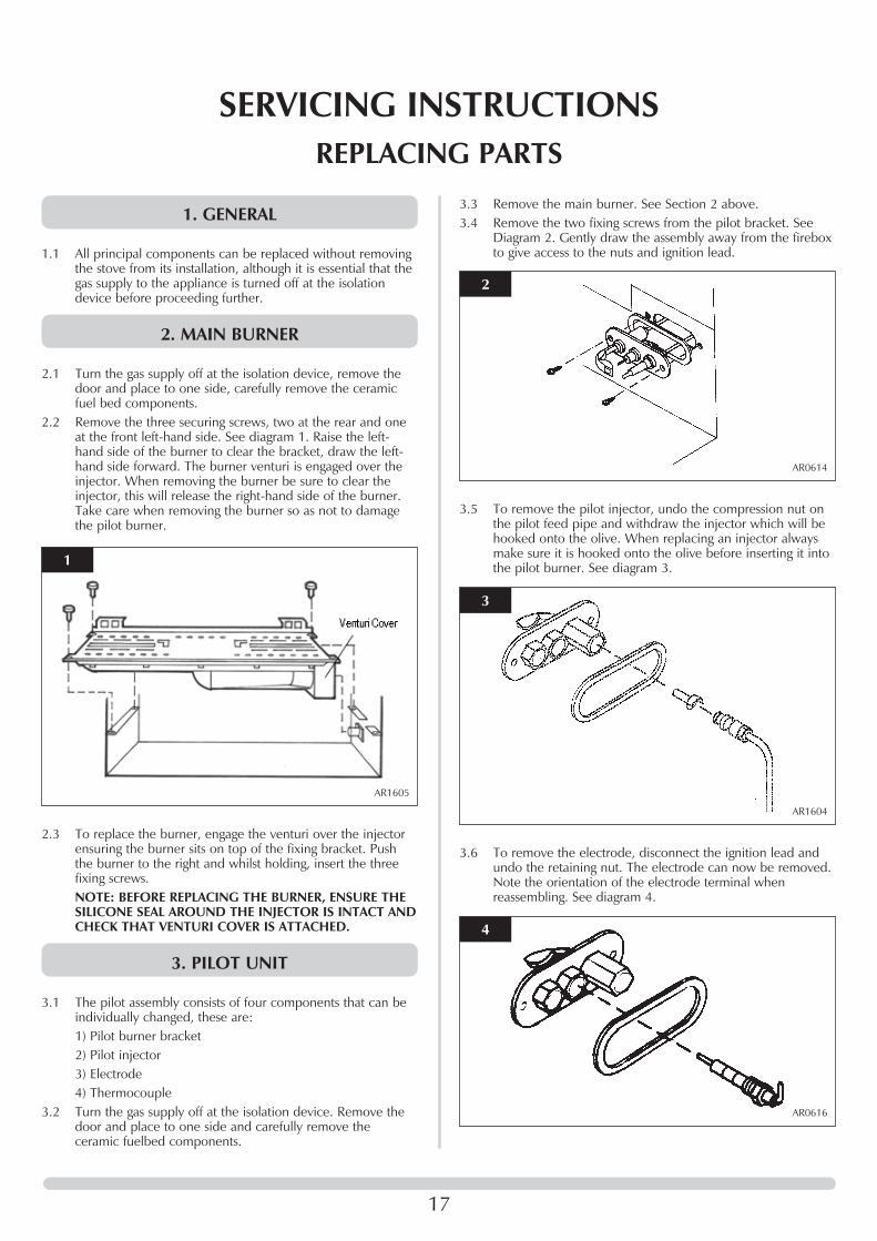
1. GENERAL
1.1 All principal components can be replaced without removingthe stove from its installation, although it is essential that thegas supply to the appliance is turned off at the isolationdevice before proceeding further.
2. MAIN BURNER
2.1 Turn the gas supply off at the isolation device, remove thedoor and place to one side, carefully remove the ceramicfuel bed components.
2.2 Remove the three securing screws, two at the rear and oneat the front left-hand side. See diagram 1. Raise the left-hand side of the burner to clear the bracket, draw the left-hand side forward. The burner venturi is engaged over theinjector. When removing the burner be sure to clear theinjector, this will release the right-hand side of the burner.Take care when removing the burner so as not to damagethe pilot burner.
2.3 To replace the burner, engage the venturi over the injectorensuring the burner sits on top of the fixing bracket. Pushthe burner to the right and whilst holding, insert the threefixing screws.NOTE: BEFORE REPLACING THE BURNER, ENSURE THESILICONE SEAL AROUND THE INJECTOR IS INTACT ANDCHECK THAT VENTURI COVER IS ATTACHED.
3. PILOT UNIT
3.1 The pilot assembly consists of four components that can beindividually changed, these are:1) Pilot burner bracket2) Pilot injector3) Electrode4) Thermocouple
3.2 Turn the gas supply off at the isolation device. Remove thedoor and place to one side and carefully remove theceramic fuelbed components.
AR1605
1
3.3 Remove the main burner. See Section 2 above.3.4 Remove the two fixing screws from the pilot bracket. See
Diagram 2. Gently draw the assembly away from the fireboxto give access to the nuts and ignition lead.
3.5 To remove the pilot injector, undo the compression nut onthe pilot feed pipe and withdraw the injector which will behooked onto the olive. When replacing an injector alwaysmake sure it is hooked onto the olive before inserting it intothe pilot burner. See diagram 3.
3.6 To remove the electrode, disconnect the ignition lead andundo the retaining nut. The electrode can now be removed.Note the orientation of the electrode terminal whenreassembling. See diagram 4.
AR0614
2
AR0616
4
AR1604
3

18
SERVICING INSTRUCTIONSREPLACING PARTS
3.7 To remove the thermocouple, undo the retaining nut andwithdraw the thermocouple. Undo the thermocouple fromthe back of the gas valve. See Diagrams 5 and 6. Reassemblein reverse order. Do not overtighten.
NOTE: SPECIAL CARE SHOULD BE TAKEN WHENREPLACING THE THERMOCOUPLE TO THE BACK OFTHE GAS VALVE ENSURING THAT THE SENSOR WIRESFOR THE GAZCO FLUE SURE SYSTEM ARE NOTDISCONNECTED.
4. IGNITION LEAD
4.1 Gain access to the back of the pilot assembly, see Section 3above and disconnect the ignition lead from the electrode.
4.2 Undo the single screw that secures the left-hand side of thecontrol cover, see Diagram 7.
4.3 To release the right-hand side of the control cover insert thenarrow blade screwdriver into the slot shown in diagram 8.Lever it gently and pull from the right-hand side at the sametime. The cover will now come off. There is a smallcylindrical metal spacer inside the cover; this must be keptand replaced on the fixing screw during reassembly.
4.4 Disconnect the end of the ignition lead from the valve body,see diagram 9, Arrow B, note the existing route of theignition lead.
4.5 Replace with a new ignition lead following the same route asthe old one. Replace the valve cover and the pilot assembly.
4.6 Check the operation of the new ignition lead.
5. PIEZO
5.1 The piezo assembly used on this appliance is not serviceableand is unlikely to fail.
6. GAS VALVE
6.1 Turn the gas supply off at the isolation device.6.2 Disconnect the 2 x 8mm and 1 x 4mm gas pipe fittings at
the back of the gas valve and also disconnect thethermocouple, see Diagram 10, Arrow A.
6.3 Remove the control valve cover and disconnect the ignitionlead from the gas valve, see section 4.
6.4 Undo the two bolts securing the gas valve to the applianceand remove the valve, see diagram 10, Arrow C
6.5 Replace in reverse order.
AR0617
5
AR0943
6
AR0915
7
AR0916
8
AR0943a
9

19
SERVICING INSTRUCTIONSREPLACING PARTS
6.6 Check all joints for gas leaks. Check the operation of thethermocouple and ignition lead.
7. MAGNETIC SAFETY VALVE
7.1 Turn the gas supply off at the isolation device. Undo thethermocouple connection from the back of the gas valve.Pull the sensor leads clear and remove the interrupter block.
7.2 Undo the mag valve retaining nut at the back of the controlvalve. Gently tap out the mag valve and replace with a newunit. Replace the retaining nut and tighten. See diagram 11,Arrow A.
7.3 Reassemble the interrupter block and leads. Secure thethermocouple connection in the rear of the gas control (Donot overtighten). Turn the gas supply on and check theentire pipework and valve joints for any leaks.
8. MAIN INJECTOR
8.1 Turn the gas supply off at the isolation device. Refer toSection 2, Replacing Parts to remove the main burner.
8.2 Undo the compression nut from the feed pipe at the gascontrol under the appliance.
8.3 Working from inside the firebox, remove the lock nut fromthe injector, see diagram 12 and withdraw the injectorcomplete with the feed pipe from under the appliance. Seediagram 12.
8.4 Holding the injector with a spanner, undo the feed pipe.NOTE: THE ORIENTATION OF THE INJECTOR.
8.5 Reassemble in reverse order. Turn on the gas supply andcheck for any leaks.
9. GAZCO FLUE SURE SYSTEM
9.1 Remove the front door by undoing the four dome nuts andremove the cast iron door. NOTE: THE CAST IRON DOORIS HEAVY. TAKE EXTREME CARE WHEN HANDLING.Carefully remove the coal retainer and ceramic componentsand place to one side. Remove the burner casting byremoving the three screws located on the sides of the burnerskin.
9.2 Remove the screw on the back panel and remove the panel.Refer to Diagram 14.
AR0943b
10
AR0618
12
AR0943c
11
AR1605
13
AR1606
14

10. PRIMARY AERATION PLATE
10.1 Turn the gas supply off at the isolation device.10.2 Refer to Section 2 to remove the main burner.10.3 Remove the two screws on the burner skin to detach the
venturi cover from the venturi. Slide the venturi cover off theventuri as per diagram 19.
10.4 Change the aeration plates to those stated in the technicalspecification for the gas the product will be using, refer tothe databadge.
20
SERVICING INSTRUCTIONSREPLACING PARTS
9.3 Undo the two screws at the back of the firebox and carefullywithdraw the bracket.
9.4 Disconnect the two slender wires. Undo the two taptitescrews and remove the sensor and the two plastic spacers.See diagram 16.
9.5 Refit the new sensor, ensuring that the plastic spacers arebetween the sensor and the bracket. Refit the leads. SeeDiagram 17.
9.6 Feed the cable back through the hole as you replace thebracket. When the bracket is located correctly it will sitflush with the back panel without force required. If notpositioned correctly the bracket will sit at an angle. SeeDiagram 18.
AR1607
15
AR1446
16
AR1608
19
AR1452
17
AR1447 AR1448
18
AR0619
20

21
SERVICING INSTRUCTIONSREPLACING PARTS
11. CHANGING BETWEEN GAS TYPES
In order to change between gas types, it will be necessary tochange the following items.- Pilot Injector- Control Valve- Main Injector- Main Burner- Aeration Plate (if required)- DatabadgeThe relevant parts can be ordered from Gazco, always quotethe appliance type and serial number when ordering spareparts.
** NOTE: THE CONTROL VALVE IS FACTORY PRESET FORCORRECT GAS TYPE AND MODEL, A NEW UNIT WILLNEED TO BE ORDERED WHEN CHANGING BETWEENGAS TYPES.
12. CONTROL UPGRADE
See Installation, Section 1.
13. SHORT SPARES LIST
Component NG LPGG20 G30 G31
20mb 29mb 37mbMain Injector IN0045 IN0030 IN0030Aeration plate N/A N/A GZ5387Pilot injector PI0026 PI0015Burner assembly GZ5369 GZ5388Thermocouple PI0010Magnetic unit GC0092Electrode PI0053Pilot Gasket PI0052Gas valve GC0088KIgnition lead GC0090Complete log set CEO583Log A CEO584Log B CEO585Log C CEO586Log D CEO587Log E CEO588Left ash panel CEO589Right ash panel CEO590TTB EL0001TTB Lead EL0064Interupter block GC0026Standard upgrade kit 8455Thermostat/timer kit 8456
22
SERVICE RECORDS
1ST SERVICE
Date of Service:...........................................................................
Next Service Due:.......................................................................
Signed:........................................................................................
Dealer's Stamp/CORGI Registration Number
3RD SERVICE
Date of Service:...........................................................................
Next ServiceDue:........................................................................
Signed:........................................................................................
Dealer's Stamp/CORGI Registration Number
5TH SERVICE
Date of Service:...........................................................................
Next Service Due:.......................................................................
Signed:........................................................................................
Dealer's Stamp/CORGI Registration Number
7TH SERVICE
Date of Service:...........................................................................
Next Service Due:.......................................................................
Signed:........................................................................................
Dealer's Stamp/CORGI Registration Number
9TH SERVICE
Date of Service:...........................................................................
Next Due:........................................................................
Signed:........................................................................................
Dealer's Stamp/CORGI Registration Number
2ND SERVICE
Date of Service:...........................................................................
Next Service Due:.......................................................................
Signed:........................................................................................
Dealer's Stamp/CORGI Registration Number
4TH SERVICE
Date of Service:...........................................................................
Next Service Due:.......................................................................
Signed:........................................................................................
Dealer's Stamp/CORGI Registration Number
6TH SERVICE
Date ofService:............................................................................
Next Service Due:.......................................................................
Signed:........................................................................................
Dealer's Stamp/CORGI Registration Number
8TH SERVICE
Date of Service:...........................................................................
Next Due:........................................................................
Signed:........................................................................................
Dealer's Stamp/CORGI Registration Number
10TH SERVICE
Date of Service:...........................................................................
Next Service Due:.......................................................................
Signed:........................................................................................
Dealer's Stamp/CORGI Registration Number

Gazco Limited, Osprey Road, Sowton Industrial Estate, Exeter, Devon, England EX2 7JGTel: (01392) 261999 Fax: (01392) 444148 E-mail: [email protected]
A member of the Stovax Group