m a r e c o n information document onshore and coastal applications
TRANSCRIPT

M A R E C O N MARINE ENVIRONMENTAL AND CONSTRUCTION CONSULTANTS
1
INFORMATION DOCUMENT FOR
ONSHORE AND COASTAL APPLICATIONS
CONTENTS
(1) INTRODUCTION
(2) GENERAL
(3) PRODUCT INFORMATION
(4) ONSHORE APPLICATIONS
(5) COASTAL AND OFFSHORE APPLICATIONS (pipeline stabilisation and scour control)
(6) NON-STANDARD FLEXMAT APPLICATIONS
(7) SELECTION GUIDELINES
- TABLE 1: standard Flexmat data - TABLE 2: flow velocities in water courses - TABLE 3: required mattress version as a function of flow velocity - TABLES 4-6: required mattress version as a function of wave height - TABLE 7: required mattress version as a function of vehicle weight
(8) ANCHORING
(9) ALTERNATIVE FIXATION METHODS
(10) GROOVE FILLING
(11) EDGE STABILISATION
(12) CURVED ALIGNMENTS
(13) ENVIRONMENTAL ENHANCEMENT
(14) INSTALLATION
(15) MAINTENANCE
ATTACHMENTS
(1) Drawing of Standard Flexmat (2) Installation Summary Sheet (3) Tubular Lifting Assembly Specifications (4) Design Examples
1 & 2: roadways3 & 4: embankments5: commercial ramp (boat ramp)6: open drain (channel)7: spillway (chute)8: rainwater outfall

M A R E C O N MARINE ENVIRONMENTAL AND CONSTRUCTION CONSULTANTS
2
(1) INTRODUCTION
This document provides detailed DESIGN- and INSTALLATION Guidelines for professional engineers wishing to determine whether the Flexmat™ system could be applied at the project under consideration and -if so- select the most suitable Flexmat™ version.
The contents of the document are based on conservative engineering and design practice, in compliance with Australian and international Standards and Codes. (where applicable)However, as environmental- and site conditions may differ significantly from the normative conditions assumed in this document it is a condition of the use of the information in this document that all rights of action (including any claim for damages for negligence or want of care on the part of Marecon) which may arise against Marecon as a consequence of that use be irrevocably waived. To the extent permitted by law, Marecon accepts no responsibility whatsoever for any loss or damage (including any consequential loss) arising out of the selection or installation of the Flexmat system, or for the information in this document being incorrect, incomplete or misleading. You should make your own enquiries and form your own opinion as to the suitability of the Flexmat system, and the manner in which the Flexmat system should be installed.In case of doubt Marecon should be consulted (free of charge, time permitting).
(2) GENERAL
The concept of regular concrete block patterns, precast on permeable geotextile matting was developed more than thirty years ago in Western Europe. In these early mattresses the blocks were bonded to the matting by means of synthetic pins.
After introduction of the system into Australia, almost twenty years ago, the pins were replaced by a dense pattern of stiff synthetic loops tufted into the matting.
During the concrete casting- and vibrating process the loops penetrate into the fluidized base of the blocks, providing superior bonding strength between blocks and matting at significantly reduced cost. (compared to connection by pins)
As a result the precast Flexmat system is highly competitive, if compared to in-situ systems such as rip-rap, grout-filled mattresses, placed armour rock or, in case of harbour- or coastal works, rigid structures such as quay walls, sheetpiling or stacked concrete (seabee) units.
Principal merits of the FLEXMAT system are as follows:
- virtually maintenance free and long-lasting
- environmentally attractive, particularly if dyed
- adequate (broom finished) surface roughness, greatly reducing the risk of pedestrians losing their footing on slippery (algael growth) surfaces, for example in the case of boatramps.
- hydraulically smooth surface, preventing weeds, plastics or other forms of rubbish from sticking to the lining.
- retrievable and redeployable in case of seasonal boatramps or other temporary applications or in cases where smoothing of the deformed (subsided) base layer is required.
- insensitive to vandalism (if installed correctly)

M A R E C O N MARINE ENVIRONMENTAL AND CONSTRUCTION CONSULTANTS
3
(3) PRODUCT INFORMATION
Standard Flexmats consist of a uniform rectangular pattern of square trapezoidal concrete blocks cast onto durable polypropylene fabric, called loopmatting. Mattress dimensions and other parameters are presented in Attachment 1.
Concrete durability is assured by adopting the right type of cement and aggregates for the anticipated envi-ronmental conditions. (ensuring adequate imperviousness when applied under water)
The matting has excellent durability in water and on land, containing special additives toprovide long term protection against leaching degradation in (sea)water and/or UV light.
The matting also has good resistance to bio-organisms, common chemicals, abrasion and wear and tear. More information and the results of extensive testing programmes are contained in the document ‘Compre-hensive Documentation on Robusta Polypropylene Matting’ (Email version is available on request)
TABLE 1: Data for standard Flexmats consisting of 18 rows of 8 blocks (*) at a concrete density of 2350 kg/m3 (with reference to Attachment 1)
block total loopmat hght (mm) wght (T) type
FM40 40 0.95 325-SFM65 65 1.50 600-SFMI00 100 2.25 600-SFMI50 150 3.30 600-S
IMPORTANT: If applied on fine erodable base material such as sand or clay with low cohesion, a separate underskirt(*) would need to be pre-installed centrally below the edge line of adjoining mats to prevent wash-out of such material in cases of wave action and/or current and, in the case of onshore embankments, heavy rainwater runoff from higher terrain. (with substantial catchment area)
(*) strips of light (non-woven or woven) fabric such as Bidim A12, Propex 2001 or equivalent. Required strip widths: FM40: 0.9m: FM65: 1.3m; FM100 and FM150: 1.9m
Note: In cases of fully submerged scour control Flexmats™, installation of strips may be problematic and/or costly, especially in relatively deep water. In such situations the use of strips can be avoided by decreasing the number of blocks per row(*) during the casting process rendering in a wider loopmatting skirt (with suf-ficient overlap width) (*) at an additional installed cost as indicated below. (per square metre of concrete block area) For unchanged concrete density of 2350 kg/m3 and 18 block rows per mattress, the numbers for each
version then become as follows:

M A R E C O N MARINE ENVIRONMENTAL AND CONSTRUCTION CONSULTANTS
4
Mattress no. of blocks mat weight indicative extra cost version: per row: (in Tonnes) per m2 (in %)FM40 7 0.80 5FM65 6 1.10 10FMI00 5 1.40 15FMI50 5 2.10 15
Note: If there is no risk of slippage, creep or hydrodynamic lift, the strips are only required if there is a risk of the (fine) base material escaping at the joint lines during rainfall run-off or wave-induced wash.
(4) ONSHORE APPLICATIONS
These are categorized as follows:recommended
TERRAIN MATS for: type:
- bicycle tracks FM40
- pedestrian passage ways, malls, walkways in FM40 parks, jogging tracks, beach/dune crossings
- terrain cover in utility areas (requiring occasional access to buried drains/cables) FM40(*)
- farm applications (cattle feed areas, pens and other hardstand areas) FM40(*)
- speed control humps in roads, driveways to garages, carports (also at steep inclines): FM65
- ROADWAYS to building sites, parking- and loading bays, field roads for minerals exploration, sewage re: table 7 treatment plants and other utility areas (for bogging prevention)
(*) if some block cracking is acceptable, otherwise type FM65 should be adopted.

M A R E C O N MARINE ENVIRONMENTAL AND CONSTRUCTION CONSULTANTS
5
EMBANKMENTS
- road/rail embankments and overpass abutments not exposed to vehicle traffic: FM40
- embankments as above, subject to occasional maintenance traffic: FM65
HYDRAULIC APPLICATIONS
- linings of small lakes, ponds, sewage treatment reservoirs, sumps, basins and other applications with little current or wave action (if any) FM40
- embankments of water courses, channels, lakes, reservoirs; linings of open drains re: tables 2 to 5 channels exposed to wave/current action - fully submerged mats on the floor of harbours, estuaries etc. exposed to re: table 6 significant wave/current action
- shore protection, erosion prevention or dune stabilization at exposed coastlines
- scour prevention mats below rainwater drain outlets and drop structures
(5) COASTAL AND OFFSHORE APPLICATIONS
Flexmats are also used for marine pipeline stabilisation and scour control, with a sixteen year history of successful application at many offshore projects, mainly for Woodside, WAPET and Western Mining Corp. (with reference to images on the website www.marecon.com)
Successful field testing in shallow water for pipelines up to 1200 mm diameter and subsequent application of Flexmats by Shell Brunei on its Tutong pipeline have demonstrated that, by using high-density concrete, Flexmats are also highly effective and economical for stabilisation of intake- and outfall pipelines in shallow water up to the shore point.
Consequently it is no longer necessary to tie the pipelines to a jetty or piles structure or to adopt the tradi-tional (high cost) methods of trenching or rockdumping. (anchoring should be ruled out because of consider-able failure history)
Recent examples of successful Flexmat applications in this category include CSIRO’s water intake line at Marmion (W.A.), Albany’s Aquaculture Park outfall line, SCM Chemicals Ltd’s outfall line near Bunbury and two intake- and discharge pipeline bundles at abalone farm at Bremer Bay (W.A.) (with reference to images on the website www.marecon.com)
Detailed information about the system and its applications is contained in the document ‘FLEXMAT CON-CRETE BLOCK MAT SYSTEM for Stabilization and Free Span control of Marine Pipelines’ (Email ver-sion is available on request)
M A R E C O N MARINE ENVIRONMENTAL AND CONSTRUCTION CONSULTANTS
6
(6) NON-STANDARD FLEXMAT APPLICATIONS
In situations where Flexmats heavier than FM150 would be required it would be more economical to apply non-standard Flexmats. (with increased concrete density and block size)
A typical example, as shown on website, www.marecon.com is the protection of WAPET’s facilities at Thevenard Island at the North West Shelf against cyclonic wave action.
Note: it would be technically possible to apply very heavy Flexmats, up to a weight of roughly 1 T/m2
(7) SELECTION GUIDELINES
(A) Flexmat lining mainly subject to WATER FLOW:
For example: linings of water courses, open drains, road sections (levees) subject to occasional overflow after heavy rainfall or flooding. A certain minimum mattress weight is required to counter the hydrody-namic lift force, generated by the flow velocity.
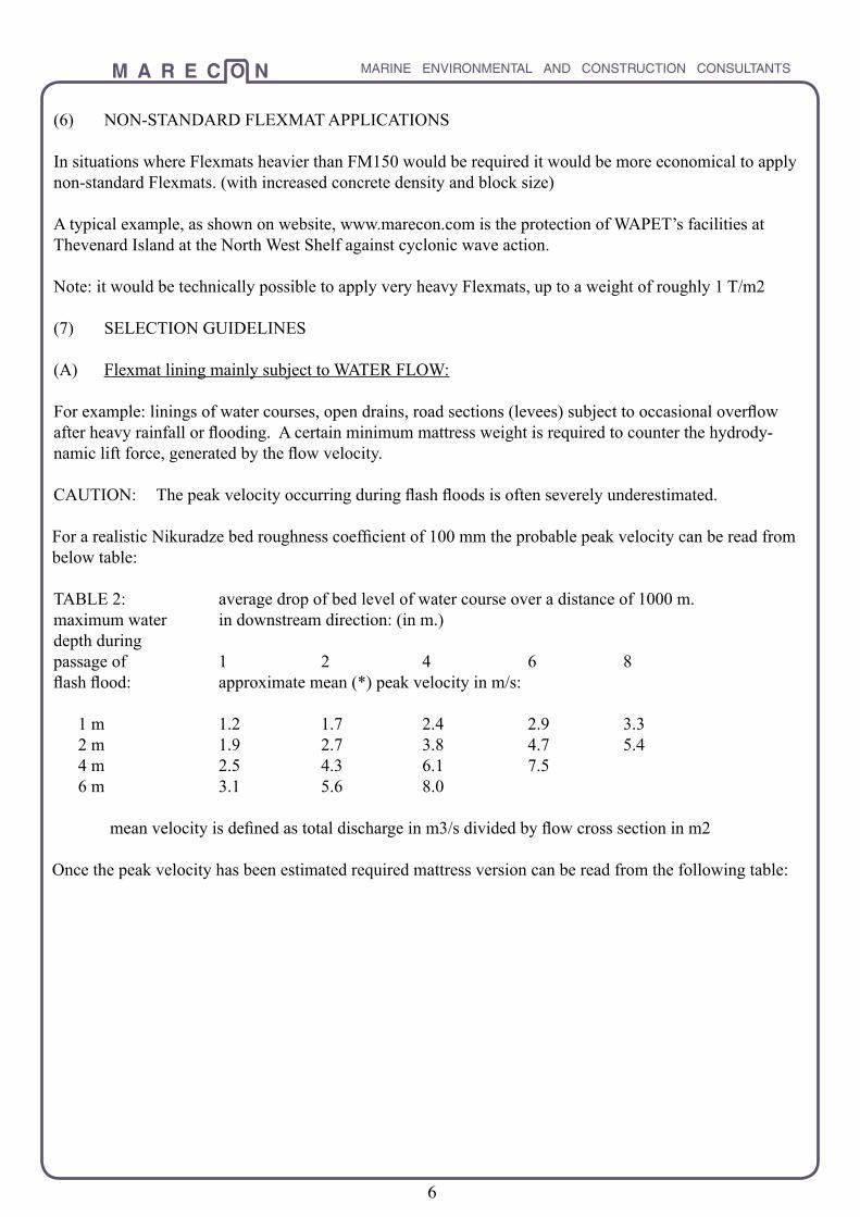
CAUTION: The peak velocity occurring during flash floods is often severely underestimated.
For a realistic Nikuradze bed roughness coefficient of 100 mm the probable peak velocity can be read from below table:
TABLE 2: average drop of bed level of water course over a distance of 1000 m.maximum water in downstream direction: (in m.)depth duringpassage of 1 2 4 6 8 flash flood: approximate mean (*) peak velocity in m/s:
1 m 1.2 1.7 2.4 2.9 3.3 2 m 1.9 2.7 3.8 4.7 5.4 4 m 2.5 4.3 6.1 7.5 6 m 3.1 5.6 8.0
mean velocity is defined as total discharge in m3/s divided by flow cross section in m2
Once the peak velocity has been estimated required mattress version can be read from the following table:

M A R E C O N MARINE ENVIRONMENTAL AND CONSTRUCTION CONSULTANTS
7
TABLE 3: ALLOWABLE PEAK VELOCITY in m/s for uniform stable(*) flow in water courses, channels and across flooded roadways, spillways, levees etc.
embankment gradient 1 : 1.5 1 : 2 1 : 4 (and gentler)
mat version: FM40 2.5 2.7 2.9 FM65 3.2 3.4 3.7 FM100 3.8 4.1 4.4 FM150 4.6 4.9 5.3CAUTION: in areas of non-uniform confined flow or downstream of turbulence generating structures such as bridge pylons, piles, groyne heads, jetties etc. there would be a large increase in hydrodynamic lift force on the Flexmat blocks. As a consequence, the allowable peak velocity decreases significantly. (the above table would no longer apply)
Note 1: if concrete density exceeds 2350 kg/m3 the allowable velocity increases in proportion to the square root of the increase in submerged weight. For example: at a density of -say- 2500 kg/m3, submerged rela-tive density increases from 1.35 to 1.50 (ratio 1.11). Consequently the allowable velocity increases by a ratio 1.05 (square root of 1.11)
Note 2: if the entire channel cross section is lined with correctly installed mats (with block level differences not exceeding 10 mm) Nikuradzels roughness coefficient (k) is approximately 5 mm. The channels flow capacity then follows from Chezy’s expression Q = 18*A*Iog(12*R/k)*((R*I)exp(.5)) in which R is hydrau-lic radius (m), A is flow cross section (m2), 1 is channel gradient and Q is flow capacity in m3/s.
(B) Flexmat lining on straight embankment without berm, mainly subject to WAVE ACTION.
It is important to correctly estimate the maximum wave height that could occur during the projeet’s design life.
In this assessment one should allow for an increase, if any, in the height of the approaching waves caused by shoaling, refraction or reflection from either the embankment itself or from nearby structures such as quay walls, groynes etc.
Maximum allowable wave height (*) immediately prior to impact on the Flexmat lining, is given in tables 4 and 5 below, for wave approach direction perpendicular to the shore line (worst case scenario) and for long-shore current at the water surface, at 10 metres distance from the lining, not exceeding 50% of the velocity limit given in table 3.(*) to prevent damage or deformation of the Flexmat lining.

M A R E C O N MARINE ENVIRONMENTAL AND CONSTRUCTION CONSULTANTS
8
TABLE 4A: wave spectrum: WIND WAVES (without swell component) base material: FINE SAND (d50 not exceeding .2 mm) or cohesive CLAY or SOIL with undis-
turbed shear strength at least 25 kN/m2 and, for clay, a consistency index not smaller than 0.75
bank gradient: 1:1.75 1:2 1:2.5 1:3 1:7 or less (*) allowable maximum weight height (in m.): FM40 .25 .30 .35 .40 - FM65 .35 .45 .55 .60 .60 FM100 .50 .60 .90 1.05 .95 FM150 .60 .75 1.05 1.40 1.40
TABLE 4B: wave spectrum: LONG REGULAR WAVES such as residual swell motion or seiches in har-bours, marina’s etc. base material: as specified above, in table 4A
bank gradient: 1:1.75 1:2 1:2.5 1:3 1:7 or less (*) allowable maximum weight height (in m): FM40 .10 .15 .25 .30 n.a. FM65 .15 .25 .35 .40 .45 FM100 .25 .35 .50 .60 .70 FM150 .35 .45 .60 .70 .90
(*) commercial ramps or boatramps with (required) bedding layer of approximately 150 mm thickness, consisting of fines or roadbase with Darcy permeability (k) not exceeding
5 mm/sec
TABLE 5A: wave spectrum: WIND WAVES (without swell component) base material: COARSE SAND (D50 at least .8 mm)
bank gradient: 1:1.75 1:2 1:2.5 1:3 1:7 or less (*)allowable maximum weight height (in m.):
FM40 .25 .25 .30 .35 n.a. FM65 .40 .40 .45 .50 .60 FMI00 .60 .65 .75 .80 .95 FM150 .85 .90 1.00 1.10 1.40

M A R E C O N MARINE ENVIRONMENTAL AND CONSTRUCTION CONSULTANTS
9
TABLE 5B: wave spectrum: LONG REGULAR WAVES such as residual swell motion or seiches in harbours, marina’s etc. Base material: COARSE SAND (D50 at least .8 mm)
bank gradient: 1:1.75 1:2 1:2.5 1:3 1:7 or less (*) allowable maximum weight height (in m.): FM40 .15 .20 .25 .25 n.a FM65 .25 .30 .35 .40 .50 FM100 .35 .45 .55 .65 .70 FM150 .50 .65 .70 .80 .90
(*) bedding layer is not required as (compacted) sand is strong enough to absorb typical vehicle wheel loadings (up to 4WD) without deformation (rutting)
For MEDIUM sand (0.2<d50<0.8 mm) the allowable wave height is found by averaging the values found for fine and coarse sand.
Note 1: in cases of highly permeable base material, e.g. rock groynes, it is necessary to apply a bedding layer of fines or roadbase with a thickness of at least three times required block height. In such cases NON-STANDARD Flexmats should be applied. (adequate design could be provided by Marecon)
Note 2: in case of wave action generated by ships or leisure craft, the above tables 4B and 5B would apply.
TABLE 6: ALLOWABLE MAXIMUM (reflected) WAVE HEIGHT (in m) for FULLY SUBMERGED FLEXMATS resting on sand, for bed gradient not steeper than 1 : 5 and a steady current at 1 m. above bed level not exceeding 50% of the allowable value given in table 3, for concrete density of 2350 kg/m3
depth (d) in m. 2 3 5 7 10
FM40 .40 .60 1.00 1.45 1.90FM65 .70 1.00 1.60 2.20 2.80FM100 .95 1.40 2.10 2.90 3.70FM150 1.35 1.85 2.85 3.75 4.60
Note: at a concrete density higher than 2350 kg/m3 allowable wave height figures given in above tables increase in linear proportion to the increase in concrete density.
(C) FLEXMATS FOR COASTAL PROTECTION
At oceanic and other locations exposed to severe wave action, heavy NON-STANDARD Flexmats would need to be applied. (with enlarged, high-density, blocks of oblong shape)In the previously mentioned example of coastal stabilisation at Thevenard Island (W.A), heavy Flexmats with a weight of 0.54 T/m2 were applied to provide the required protection during extreme cyclonic events, for an assumed (breaking) design wave height of 3.5 m.Designs for similar applications can be provided by Marecon. (time permitting)

M A R E C O N MARINE ENVIRONMENTAL AND CONSTRUCTION CONSULTANTS
10
(D) Flexmat lining below DRAIN OUTFLOWS and DROP STRUCTURES
The Flexmat lining is potentially subject to instability due to increased pore pressure and associated steep pressure gradients in the base material.
This could cause mattress uplift and/or surface deformation due to lateral particle migration or shear failure in the base material.
To prevent this from happening a minimum dry lining weight is required, as indicatively given by the expression:
Wm = .3 * h(exp(0.875)) * Q(exp(0.5) (*)whereby the expression ‘exp’ stands for ‘to the power of’in which:
- Wm is required dry Flexmat weight in T/m2
- Q is flow rate in m3/sec
- h is head drop (‘fall height’) in m.
(*) applying to a base material of fine sand (worst case scenario) and subject to the condition that the block grooves are to be filled to -at least- half block height with lean grout, with reference to installa-tion procedure outlined in par. 8
(E) Standard Flexmat lining subject to VEHICLE TRAFFIC
TABLE 7: Recommended Flexmat type for vehicle traffic on boatramps, commercial ramps, driveways, parking bays, roadways and road shoulders
- cars or lighter vehicles: FM40
- 4WD vehicles, light trucks and trailered up to a weight of approximately 5 Tonne: FM65
- tyred vehicles up to a loaded weight of approximately 15 Tonne: FM100
- heavy tyred vehicles (from 15 T. upward) FM150

M A R E C O N MARINE ENVIRONMENTAL AND CONSTRUCTION CONSULTANTS
11
Note: if traffic is sporadic or slow (for example maintenance vehicles) or if some cracking (*) of blocks over time can be accepted, the preceding -lighter- mat version can be adopted.
(*) this type of damage would not adversely affect mattress performance as the fractured block components would remain attached to the embedded matting loops.
CAUTION: Flexmats or other lining types do not significantly increase the internal stability of the supporting base material. Consequently, at relatively steep embankment, the internal slipcircle stability of the base material should be checked by means of, for example, Bishop’s well known slices method.
(8) ANCHORING
Normally, the FLEXMATS would require anchoring to prevent creep or slippage caused by vehicle motion or wave dynamics. For this purpose standard steel anchor pins are most often used. The short pins are used for type FM40 whilst the long pins are used for all heavier Flexmat versions.
At each mattress, the transverse pins are placed between the upper edge block rows 1 and 2, as shown. In case of vehicle loading this is the edge facing the main traffic flow.
The pins are driven down until wedged between the blocks. During the final stage, when the pin head approaches the block surface, a steel extension rod is used in order to prevent hammer impact (chipping) damage to the block’s edges. Pin driving is halted as soon as the pin head become wedged between the blocks, preventing contact with the matting.

M A R E C O N MARINE ENVIRONMENTAL AND CONSTRUCTION CONSULTANTS
12
The number of anchor pins required to prevent creep, slippage or hydrodynamic lifting of blocks is estab-lished as follows:
(a) for Flexmat lining of flow channels, water courses, open drains etc. without significant wave action:
At the section of the lining that would be permanently or occasionally submerged (during floods) the upstream edge row of blocks facing the flow direction is anchored by 1 pin every 2rd block (this is nec-essary to counter the additional lift force generated if the edges of the upstream blocks protrude above the mean lining surface.)
For the more elevated, permanently ‘dry’, section of the lining, at gradients steeper than 1 in 3, anchor pins may be required transversely (as calculated according to expression 2 below) to prevent downward mattress slippage.
(b) for Flexmats on embankments exposed to wave action:
np1 =Wmat*(sin(a)-0.33*cos(a))/Fa (1)
(c) for Flexmats exposed to vehicle traffic:
np2 =(0.15*Wveh*cos(a)+Wmat*(sin(a)-0.65*cos(a)))/Fa (2)
in which- np is number of transverse pins required per Flexmat (section) (*) with weight Wmat (in T) - Wveh is predominant vehicle weight in T. - Fa is minimum lateral holding power per pin. (for long pin: .25 T. For short pin: .125 T.)
- (a) is slope angle of embankment
(*) in cases of slow or sporadic traffic (e.g. maintenance vehicles) the calculated number of pins can be halved.
Note: for Flexmats subject to wave action and traffic loading (at different points in time) the highest calcu-lated np value should be adopted. (values of np1 and np2 not to be added up)
Note: a negative np value indicates that there is sufficient base friction against slippage. Consequently no pins would be required, up to a positive np value of 2 (due to the generous safety margin in above expres-sions) For np values between 2 and 3.5 the number of pins should be rounded up to one installed pin every second block transversely and one pin every fourth block longitudinally. These figures are also the mini-mum required transverse and longitudinal spacings in permanent roadway applications. to avoid gradual lateral mattress separation over time.
Normally, longitudinal pins are spaced twice as wide as the transverse pins (without exceeding 1 pin every 4th block)

M A R E C O N MARINE ENVIRONMENTAL AND CONSTRUCTION CONSULTANTS
13
Note: if anchoring is required it is important that, on embankments steeper than 1 in 3, one ensures that:
(a) proper anchoring occurs at all joint lines to ensure that all mats are interconnected, acting as one large assembly.
(b) the top edge of the upper mats to be well fixed in order to eliminate any risk of the entire Flexmat assembly sliding downslope. (with reference to the alternative fixation methods described in par. 9)
Note: by interconnecting all Flexmats in downslope direction, the slippage force is not primarily absorbed by the holding power (*) of the pins in the base material but, rather, by the tensile strength of the intercon-nected matting.
(*) which may be low in soft base material
(9) ALTERNATIVE FIXATION METHODS
(a) by means of grouting
Mattress block rows would need to be cast centrally, with equal skirt width at either side.
After installation, the skirts of adjoining mats are tightly rolled up and firmly pinned down by means of knit-ting-type needles, placed at at approximately 0.5 m. intervals.
The gap (roughly one block wide) is then filled by means of a grout pump/hose system. This method is eco-nomical and preferable if visual appearance is irrelevant. (e.g. under water)
(b) by means of steel cords
This method is advantageous if there is the prospect that mattresses may, at some point in future, need to be lifted and repositioned. (in such situation it would be easy to disengage the cord system)
After installation of the mattresses the flexible stainless steel cords are directed through small diameter pvc tubes, precast in every second edge block.

M A R E C O N MARINE ENVIRONMENTAL AND CONSTRUCTION CONSULTANTS
14
This ‘shoe lacing’ method was successfully applied at the Thevenard project mentioned in par. 5C of this document.
(c) by means of steel strip connectors (or pins driven into pre-drilled holes)
In case of hard base material such as rock or limestone the Flexmats are to be placed on a bedding layer of sand, fines or roadbase. Such layer would normally be thin, with just suf-ficient thickness to fill the depressions between the base materials protrusions. Consequently anchor pins would not penetrate deep enough to render sufficient holding power.
In such situation one could use steel strip con-nectors as shown above. The number of connectors required would be half of the required number of anchor pins, subject to spacings not exceeding specified upper limits.
In areas accessible to the general public it is recommended (if the block grooves are left unfilled) to ‘fix’ each connector by means of small lumps of grout.
Alternatively it is possible to use anchor pins after having drilled holes at the pin’s intended locations, with hole diameter equal to anchor pin diameter.
The pointed pins, reduced to roughly half length, are then hammered in, providing adequate holding power as a result of tight fit. By using a drill with elongated stem, holes can be drilled to considerable depth under water, for adequate pinning of fully submerged mattress sections.
This method was found to be effective during upgrading of the Leeuwin Barracks ramp in the Swan River (W.A) where a Flexmat lining was placed directly on top of a degraded (cracked) concrete ramp. (using pins at one third of standard length)
(10) GROOVE FILLING
In traffic applications it is beneficial to fill the grooves to, roughly, half block height with a lean mix of blue metal, sand (10%) and cement (5%)
The mix is then brushed into the grooves and its adhesion, after curing, will prevent any substantial dislodg-ing of particles from the grooves.
Such measure eliminates potential mattress slippage or creep. As a result the required number of anchor pins can be halved by doubling the pin spacings.
In addition, groove filling prevents the growth of weeds and effectively shields the matting from UV light.

M A R E C O N MARINE ENVIRONMENTAL AND CONSTRUCTION CONSULTANTS
15
(11) EDGE STABILIZATION
If the mattress’ edges could be undermined by scour or if there is a perceived risk of vandalism in areas accessible to the general public it is recommended to bury the edge skirts as well as any exposed head skirts or toe skirts.
Note: in water courses with erodable bed material the toe of the lining needs to be extended to cope with possible descent of the mean bed level during the lining’s design life.
CAUTION: in the case of boatramps the toe skirt should be cut off to prevent the exposed, buoyant, skirt from getting hooked by the under-carriage of trailers or the skeg of outboard engines.
Also and most importantly, the toe row of blocks should be at least 1 m. (*) below the lowest possible water level, to prevent lifting of blocks by the hydrodynamic lift force generated by propeller wash.
(*) for typical conditions
If necessary, at low water, the toe row of blocks could be lowered by manual excavation along its edge (using spades or rakes), creating a trench into which the undermined toe block row would collapse.
In marine applications the fill material used for the burial and weighing down of skirts would be concrete rubble, rock or limestone pieces with average particle weight at least three times the weight of a single Flex-mat block.
In dry applications the side skirts could be stabilised by any low-cost granular material as may be available such as (compacted) sand, soil, clay, fines, blue metal or road base.
Note: in boatramp applications it would be beneficial to cover the top skirt by extending the bitumen- or concrete seal of the access road onto the fully stretched, skirt up to the first (upper) row of blocks.
If the road seal material has sufficient tensile strength, the penetration of loops into the seal would effec-tively prevent the upper mattresses from sliding downslope and, as a consequence, would eliminate the need to anchor the upper mats by pinning.

M A R E C O N MARINE ENVIRONMENTAL AND CONSTRUCTION CONSULTANTS
16
In dry applications accessible to the general public one may consider to bury the edge row of blocks. It would eliminate the risk of vandalism by making it virtually impossible to manually dislodge the edge blocks.
(12) CURVED ALIGNMENTS
In non-straight alignments, tapered mats would be required. These could be precast.
A more flexible option would be to cut the lighter Flexmat versions, up to FM100, to the required shape on site. A portable disk grinder is used to cut through the blocks at the intended cut line.
Mats would also be cut to fit the outline of adjoining structures. Any gaps remaining would then be grouted up if there is a risk of the base material escaping, using a grout pump with pressure hose in underwater applications.
(13) ENVIRONMENTAL ENHANCEMENT
In environmentally sensitive areas it would be beneficial to dye the concrete grout during manufacture or to spray the blocks after curing, using UV-resistant paint, in order to ensure the the lining would blend in well with surrounding natural materials such as limestone or grass.
In regions with sufficient rainfall the visual appearance of embankment Flexmats could be further enhanced by filling the grooves with grass-seeded soil.
(14) FLEXMAT INSTALLATION
Flexmats can be swiftly installed, using a tubulars/slings/hooks assembly as shown in Attachment 3. The squeezing arrangement, as shown ensures that the suspended mattress can not dislodge prematurely.
The mats are normally lifted by mobile crane from one end. However, for short mats with reduced number of block rows, a front-end loader or back-hoe could be used.
No special installation expertise is required except for normal care to be exercised by machine operator and supervisor, in accordance with detailed instructions as summarized in attachment 2.
Note: heavy non-standard Flexmats, including those for marine pipeline stabilisation and scour control, are provided with swiftlift points at every second block and installed by means of a parallel beam installation frame.

M A R E C O N MARINE ENVIRONMENTAL AND CONSTRUCTION CONSULTANTS
17
Installation directives can be summarized as follows:(a) base material to be well-smoothed by means of transverse skimmer beam (supported at its ends by
longitudinal ‘runner’ beams) followed by mechanical compacting.
(b) in marine application: mats to be installed at the lowest possible water level. It may be feasible to install the Flexmats ‘in the dry’ by constructing a temporary bund wall of sand or soil. (e.g. in case of boatramps)
(c) during mattress suspension the lifting tubulars must be kept perfectly horizontal, to avoid progres-sively worsening misalignment (skewing) of successive mattresses.
(d) special care should be taken that the side skirt is fully stretched (not dislodged by wind) at the moment the blocks of the following Flexmat touch down on it. (to ensure that effective overlap width is not reduced)
The installation directives are condensed in attached summary sheet. It is crucial that it is handed to the installation supervisor on site, well before the work commences.
(15) MAINTENANCE
Over time, some cracking or chipping of blocks could occur, caused by excessive wheel loads, dropped objects etc. At a certain stage of cumulative damage the affected blocks should be cut out and replaced by a precast insert section.
Its skirt, at least 800 mm wide in all directions, is then pushed sideways below the surrounding blocks until fully stretched and then secured by pins as shown.
Single damaged or crushed blocks can be replaced by chipping away the concrete residue without damag-ing the base matting and then perform an in-situ recast, using a portable (single or double) block mould, made out of steel or plywood.
Document revision 14(d.d 20 September 2005)
Prepared and solely owned (*) by MARECON Pty. Ltd. Tel: (61) 8 9445 2772 Fax: (61) 8 9445 3773 Mobile: 0409 3666 12 Email: [email protected]
(*) with full copyright- and infringement protection in accordance with relevant Australian and International legislation.

M A R E C O N MARINE ENVIRONMENTAL AND CONSTRUCTION CONSULTANTS
18
DRAWING OF STANDARD FLEXMAT for mattress versions FM40 to FM150.
ATTACHMENT 1
road seal or grass verge
(*) WWW.MARECON.COM The website contains full information about the Flexmat System including comprehensive design- and installation guidelines for Consulting- and Public Service Engineers (including typical design calculations and detailed visual information in the form of many pictures of applications, in Australia and abroad)
GROOVE FILLING: brushed in grout (in dry applications) and (optional) fines in hydraulic appli-cations (as specified on website)
Concrete density: 2.35 T/m3Strength: 30 MPa Concreted mat area: 11.7 m2 Weights:FM40: 0.90 T. FM65: 1.5 TFM100: 2.2 T FM150: 3.3 T
optional head skirt (only required if, downslope, more than one mattress is required.)
MAIN FEATURES:- easy and fast installation- highly UV resistant- long life in (sea)water- hydraulically smooth (low head loss
in flow channels)- environmentally (visually) attractive,
especially if concrete is dyed- allows ‘beaching’ of pleasure craft
without risk of holing
ANCHORING:is required in cases of substan-tial traffic or hydrody-namic loading(*) with ref. to website document(*) requiring anti-scour under-layer (BidimA14 or equiv.)Strip width: 15 times block height, placed centrally below mattress joint lines.
lower mat
upper mat
RANGE OF APPLICATIONS (summary)- lining of embankments (‘dry’ and marine)- riverbed and seafloor scour prevention- lining of flow channels and open drains- boatramps, access roadways to farms and
mining sites; pathways (FM40) across national parks and dunes (beach access)
- seasonal and permanent boatramps. (safe to walk on due to high surface friction)
M A R E C O N MARINE ENVIRONMENTAL AND CONSTRUCTION CONSULTANTS
19
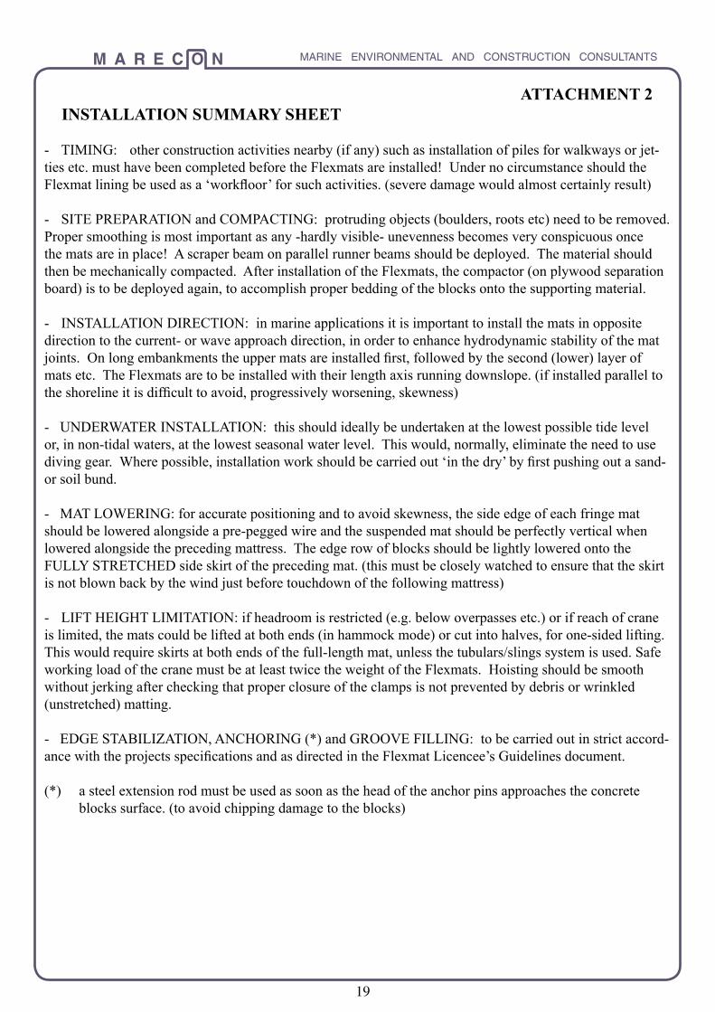
ATTACHMENT 2INSTALLATION SUMMARY SHEET
- TIMING: other construction activities nearby (if any) such as installation of piles for walkways or jet-ties etc. must have been completed before the Flexmats are installed! Under no circumstance should the Flexmat lining be used as a ‘workfloor’ for such activities. (severe damage would almost certainly result)
- SITE PREPARATION and COMPACTING: protruding objects (boulders, roots etc) need to be removed. Proper smoothing is most important as any -hardly visible- unevenness becomes very conspicuous once the mats are in place! A scraper beam on parallel runner beams should be deployed. The material should then be mechanically compacted. After installation of the Flexmats, the compactor (on plywood separation board) is to be deployed again, to accomplish proper bedding of the blocks onto the supporting material.
- INSTALLATION DIRECTION: in marine applications it is important to install the mats in opposite direction to the current- or wave approach direction, in order to enhance hydrodynamic stability of the mat joints. On long embankments the upper mats are installed first, followed by the second (lower) layer of mats etc. The Flexmats are to be installed with their length axis running downslope. (if installed parallel to the shoreline it is difficult to avoid, progressively worsening, skewness)
- UNDERWATER INSTALLATION: this should ideally be undertaken at the lowest possible tide level or, in non-tidal waters, at the lowest seasonal water level. This would, normally, eliminate the need to use diving gear. Where possible, installation work should be carried out ‘in the dry’ by first pushing out a sand- or soil bund.
- MAT LOWERING: for accurate positioning and to avoid skewness, the side edge of each fringe mat should be lowered alongside a pre-pegged wire and the suspended mat should be perfectly vertical when lowered alongside the preceding mattress. The edge row of blocks should be lightly lowered onto the FULLY STRETCHED side skirt of the preceding mat. (this must be closely watched to ensure that the skirt is not blown back by the wind just before touchdown of the following mattress)
- LIFT HEIGHT LIMITATION: if headroom is restricted (e.g. below overpasses etc.) or if reach of crane is limited, the mats could be lifted at both ends (in hammock mode) or cut into halves, for one-sided lifting. This would require skirts at both ends of the full-length mat, unless the tubulars/slings system is used. Safe working load of the crane must be at least twice the weight of the Flexmats. Hoisting should be smooth without jerking after checking that proper closure of the clamps is not prevented by debris or wrinkled (unstretched) matting.
- EDGE STABILIZATION, ANCHORING (*) and GROOVE FILLING: to be carried out in strict accord-ance with the projects specifications and as directed in the Flexmat Licencee’s Guidelines document.
(*) a steel extension rod must be used as soon as the head of the anchor pins approaches the concrete blocks surface. (to avoid chipping damage to the blocks)

M A R E C O N MARINE ENVIRONMENTAL AND CONSTRUCTION CONSULTANTS
20
TUBULARS LIFTING ASSEMBLY SPECIFICATION FOR STANDARD FLEXMATS
(1) ACCESSORIES:
- 2 Tubulars (ERW electronic resistance welded linepipe, grade 350) Length: 2800 mm each- 2 wire rope slings with end loops, as shown below- 2 hooks (mild steel) as shown below. (to prevent slippage of slings along tubular)
Allowable mattress weights as a function of pipe diameter and wall thickness are as follows: (for a lifting angle of slings at least 45 degrees, as shown below)
Tubulars: Hooks Allowable mat OD wall thickness rod diam. weight in (mm) (mm) d in mm: metric Tonnes
88.9 5.5 12 1.0 114.3 6.0 14 1.7 141.3 6.5 16 2.4 168.3 6.4 18 3.4
ATTACHMENT 3

M A R E C O N MARINE ENVIRONMENTAL AND CONSTRUCTION CONSULTANTS
21
cross section (n.t.s.)
Assumed traffic: 4WD vehicles and light trucks.According to table 7: mattress version FM65 is required Mattress weight, for 8 block rows (as shown):From table 1: Wmat = (8/20)*1.65 = 0.66 T.
From par. 8, expression (2) for -say- level road and assumed predominant laden vehicle weight of -say- 7.5 T: np=0.15*Wveh*cos(a)+0.66*cos(a)+Wmat*((sin(a)-0.65*cos(a)))/Fa so that, for sin(a)=0, cos(a)=1 and Fa=0.25 T: np=(0.15*7.5*1.0+0.66*(0-0.65*1.0))/0.25=2.8 (*)
This is larger than 2.0 so that number of pins needs to be rounded up to one pin every second block, as shown below:
Comments: in the case of field roads inaccessible to the public the mat’s edges would not normally be buried. Full length (or overlength) mats, 7 or 8 blocks wide, could then be installed lengthwise, reducing the number of joints and pins required.Also: grouting of the grooves would eliminate any risk of creep.
Design Example 1ROADWAY (Either permanent, for example to farm building or temporary, for example to construction site)
Sheet 1 of 8

M A R E C O N MARINE ENVIRONMENTAL AND CONSTRUCTION CONSULTANTS
22
Design Example 2ROADWAY LEVEE (scour protection at the shoulders of occasionally overflowing roadway sections)
cross section(n.t.s.)
Design overflow velocity:
- for upstream area (l): vl≈ 3.2*h0.5 (1)
- for downstream area (2): v2≈5.5*h0.5 (2)
For an assumed maximum head (h) of -say- 0.5 m.
- area (l): v1=3.2*(0.5)0.5 = 2.3 m/s. From table 3: adopt FM40- area (2): v2=5.5*(0.5)0.5 = 3.9 m/s. From table 3: adopt FM100
Note: if the road shoulders also would need to cope with (temporarily) parked vehicles and/or operation of maintenance vehicles heavier than -say- 5 T: from table 7: adopt FM100 This implies that, in such situation, mattress version FM100 would be required in both areas (1 and 2)
Anchor pin requirement and spacing: similar to cale. example 1
(*) minimum skirt length: at least 1.5 times head drop (h)(**) as required by customer
Sheet 2 of 8

M A R E C O N MARINE ENVIRONMENTAL AND CONSTRUCTION CONSULTANTS
23
Design Example 3ROAD (OVERPASS) EMBANKMENT
Sheet 3 of 8
In regard to area (1), no vehicle traffic is possible because of the steepness of the bank: mattress version FM40 would suffice. Anchor pins are not required, provided that the upper skirt of the mats is adequately buried under compacted sand or soil fill.,
In regard to area (2), for medium weight (maintenance) trafficup to vehicle weight of -say- 4 T. acc. to table 7, required mattress version would be FM65. Anchor pin requirement, ace. to par.8, expression 2, would be minimal, with reference to calculation examples 1 and 2.
Mattresses (1) would be installed first, after which the upper block rows of each mat-tress (2) are lowered onto the end skirt of mattress (1), as shown above.

M A R E C O N MARINE ENVIRONMENTAL AND CONSTRUCTION CONSULTANTS
24
From tables 4A and 5A (by linear interpolation): required Flexmat version is FM100
Required no. of anchor pins for mattress of -say- 16 block rows and 7 blocks per row:
From table 1: Wmat=(16/20)*2.35=1.88 T. From par. 8, expression (l):np= Wmat*sin(a)-0.33*cos(a))/Fa= (1.88*0.45-0.33*0.89)/0.25= 2.2 This is larger than 2 so number of pins to be rounded up to 3.5 (one pin every second block: pin spacing 572 mm)
Note 1: instead of driving the pins between block rows 1 and 2 it is preferable to drive the pins into the upper skirt, as shown above, at the same (572 mm) spacings.
Note 2: if light (maint.) vehicles would traverse the lining, expression (2) renders, for a vehicle weight of--say- 3.0 T. np= (0.15*Wveh*cos(a)+Wmat*(sin(a)-0.65*cos(a)))/Fa or np= (0.15*3.0*0.89+1.88*(0.45*-0.65*0.89)))/0.251-0.6 This value is smaller than 2.0 so that no pins would be required at the top. However, the above requirement against wave action (1 pin required every 2nd block) would prevail.
Note 3: if there is a ‘split’ mattress situation, as shown in calculation example 5, the lower inats would need to be pinned as shown, to prevent downslope creep of the upper row of blocks. Longitudinal pins are required at the (usual) double spacing of the transverse pins at a (max) spacing of 1 pin every 4th block.
Note 4: for Flexmat FM100, table 3 shows that allowable peak vel. is 3.8 m/s, 50% of which far exceeds the design current (0.5 m/s). Consequently, the use of tables 4A/5A was permitted.
Design Example 4MARINE EMBANKMENT
Sheet 4 of 8

M A R E C O N MARINE ENVIRONMENTAL AND CONSTRUCTION CONSULTANTS
25
Acc. to table 4A, for gradient 1:7 (less favourable than 1:10) required Flexmat version: FM150. (table 1: Wmat = 3.35 T.)
Acc. to table 3 its vel. limit exceeds 5.3 m/s (more than twice the longshore current value: use of table 4a was justified)
Required number of anchor pins for standard mats with 20 block rows and 7 blocks per row:
In regard to wave action, with ref. to par. 8, expression (l): np= Wmat*sin(a)-0.33*cos(a))/Fa= (3.35*0.10-0.33*1.0)/0.25= .02 This is smaller than 2.0 so that no anchor pins are required. (a small or negative value of np indicates suffi-cient base friction against downslope slippage during severe wave action)
In regard to vehicle traffic, with reference to expression (2): np= (0.15*Wveh*cos(a)+Wmat*(sin(a)-0.65*cos(a)))/Fa or np=(0.15*25*1.00+3.35*(0.10*-0.65*1.00)))/0.25= 7.6 Applying a reduction factor of 2, because vehicles would move slowly (without severe sudden deceleration as in the case of boat ramps), the required no. of pins becomes 7.6/2 = 3.8 > 3.5 Consequently the number of pins needs to rounded up to 7. (one transverse pin every block, pin spacing 286 mm)
In longitudinal direction the required pin spacing is twice as large. In other words: one pin every second block.
Note: in case of BOATRAMPS with gradient of 1:7 and vehicle weight of 2.5 T. (laden Landcruiser) one finds for mat FM150: np= (0.15*2.5*0.99+3.35*(0.14-0.65*0.99))/0.25= - 0.5 Although this (negative) value is less than 2.0 the minimum transverse pin requirement applies (1 pin every 2nd block) to prevent gradual downslope creep due to the common (improper) procedure of ‘brake launch-ing’ of boats from their trailers.
Design Example 5COMMERCIAL RAMP
Sheet 5 of 8

M A R E C O N MARINE ENVIRONMENTAL AND CONSTRUCTION CONSULTANTS
26
Acc. to table 2: approximate peak (mean) velocity is 1.9 m/s.
Acc. to table 3, for maximum runoff velocity of 1.9 m/s and gradient of 1:1.5, required Flexmat version is FM40
In the absence of significant wave action, only the upstream mattress edges would require minimum anchor-ing: 1 short pin every 2nd block. (this is to counter additional hydrodynamic lift force which occurs in areas where the upstream edge blocks protrude above the mean lining surface)
Note: if the channel or drain seasonally ‘dries out’, enabling maintenance (cleaning) vehicles to operate down the channels centre line it is necessary to check adopted mattress version. For example, for a vehicle weight up to -say- 4 Tonne, table 7 indicates that Flexmat version FM65 should be adopted unless some degree of block cracking could be accepted. (in which case FM40 would suffice)
Required number of anchor pins would be calculated in the same manner as undertaken in the roadway examples.
Design Example 6FLOW CHANNEL or OPEN DRAIN (A)WATER COURSE EMBANKMENT (B)
Sheet 6 of 8

M A R E C O N MARINE ENVIRONMENTAL AND CONSTRUCTION CONSULTANTS
27
For maximum head (h) during flood runoff, peak velocity (v) follows from: v2/(2*g) ≈ 1.5*h (Bernoulli) or v ≈ 5.5*h0.5
For max. grad. of 1:2 and head drop (h) of -say- 0.75 m. one finds: v = 5.5*(0.75)0.5 = 4.8 m/s
According to table 3 this would require mattress version FM150
If the cross section is ‘spanned’ by one full-length mattress, properly trenched at both ends, the concave pro-file generates considerable additional stability. This makes it possible to adopt the lighter mattress version FM100
In wide cross sections, covered by two (or more) mattresses the joint line(s) need to be secured by anchor pins, spaced every second block. In such case the concave profile does not generate additional stability. Consequently mattress weight can not be reduced. (FM150 to be adopted as previously calculated)
In all cases, skirt overlap with the next (adjoining) row of mattresses needs to be at least 0.5 m, to be secured by one longitudinal pin every second block.
(*) average particle weight to be twice as heavy as the Flexmat’s individual block weight.
(**) average particle weight: four times block weight.
Design Example 7OVERFLOW SILL (*)
Sheet 7 of 8

M A R E C O N MARINE ENVIRONMENTAL AND CONSTRUCTION CONSULTANTS
28
For example:For discharge (Q) of -say- 0.8 m3/s at a head drop (h) of -say- 0.6 m, from par. 7D:
dry mat weight required: Wm = .3*h0.875*Q0.25 = .181 T/m2
Acc. to table 1: required mattress version is FM100 (having a dry weight of 2.35/(2.0*5.7) = .206 T/m2)
(*) for single mattress width (in cross section), a side skirt would not be required. Consequently the number of blocks per row could be increased from 7 to 8. (w becomes 2.3 m.)
If necessary. required width (w) could be increased by installing two (or more) mattresses of standard width side by side, longitudinally joined by one anchor pin every 2nd block, driven through the skirt overlap zone.
Design Example 8DRAIN PIPE OUTFALL
Sheet 8 of 8