lumenstudiotm - lumenpulse · lumenstudio software user manual lumenstudio software user manual 4 5...
TRANSCRIPT

use with lumentouchTM 2.0 and lumencueTM controllers* Please remove protective film before use to ensure proper operation of the lumentouch controller.
software user manual lumenstudioTM

lumenstudio™ software user manual 3
Table Of Contents
LUMENPULSE, LUMENTOUCH and other trademarks indicated in this document are either trademarks of Lumenpulse Lighting Inc. or their respective owners. All rights reserved. No parts of this work may be reproduced in any form or by any means - graphic, electronic, or mechanical, including photocopying,recording, taping, or information storage and retrieval systems - without the written permission of the publisher. While every precaution has been taken in the preparation of this document, the publisher and the author assume no responsibility for errors or omissions, or for damages resulting from the use of information contained in this document or from the use of programs and source code that may accompany it. In no event shall the publisher and the author be liable for any loss of profit or any other commercial damage caused or alleged to have been caused directly or indirectly by this document.Copyright © 2015 Lumenpulse Lighting Inc., all rights reserved.
I Welcome ............................................................................................................................................ 4II Contents ............................................................................................................................................. 5III Installation .......................................................................................................................................... 6
3.1. Programming the Controller ....................................................................................................... 63.2. Connections .......................................................................................................................... 73.3. BLACKOUT Relay (energy saving) .............................................................................................. 83.4. RS232 Triggering ................................................................................................................... 83.5. Dry Contact Port Triggering ....................................................................................................... 83.6. Network Control ..................................................................................................................... 83.7. TCP Triggering ....................................................................................................................... 83.8. Remote Apps and Software Control - iPhone/iPad/Android ............................................................ 9
IV Creating A New Show ...................................................................................................................... 104.1. Adding Your DMX Devices ...................................................................................................... 10
4.1.1. The fixtures patch ........................................................................................................ 104.1.2. The areas patch .......................................................................................................... 11
4.2. Creating your scenes ............................................................................................................. 134.2.1. Fixtures selection ......................................................................................................... 13
4.2.1.1. The fixtures mode ............................................................................................... 144.2.1.1.1. Setting up the positions .............................................................................. 144.2.1.1.2. Selecting the fixtures .................................................................................. 15
4.2.1.2. The Rects mode ................................................................................................. 164.2.2. Scenes construction ...................................................................................................... 16
4.2.2.1. Adding an effect to the timelines ........................................................................... 174.2.2.2. The effects ........................................................................................................ 18
4.2.2.2.1. Static level .............................................................................................. 194.2.2.2.2. Gradient ................................................................................................. 204.2.2.2.3. Curve ..................................................................................................... 214.2.2.2.4. Color mixing ........................................................................................... 224.2.2.2.5. Matrix .................................................................................................... 234.2.2.2.6. Picture .................................................................................................... 244.2.2.2.7. Gif ........................................................................................................ 254.2.2.2.8. Video ..................................................................................................... 264.2.2.2.9. Text ........................................................................................................ 274.2.2.2.10. Color Manager ...................................................................................... 28
4.2.2.3. Rect Layers........................................................................................................ 294.2.2.4. RGBW Options ................................................................................................. 30
V Playing Your Scenes In Live Mode ......................................................................................................... 31VI Calendar Mode ............................................................................................................................... 32VII Uploading a Show - Direct to Device ................................................................................................... 33VIII Uploading a Show - Direct to SD Card ................................................................................................ 39IX Hardware Configuration ..................................................................................................................... 45X Set The Date-Time-Location Settings Via The Menu .................................................................................... 48XI Service............................................................................................................................................ 49

lumenstudio™ software user manual lumenstudio™ software user manual 4 5
I Welcome
This software has been specifically designed for the Lumentouch™ 2.0 controller and the Lumencue™. It is the perfect tool to simply create your architectural show and to control the latest generation of Lumenpulse™ products.
We will see how to setup and create your show within the next chapters. Then, we will see how to upload your show into the Lumentouch or Lumencue memory and to assign your scenes to the touch-sensitive buttons.
Please note that this a quick start type of guide and may not to apply to all installations.
II Contents
· Lumentouch 2.0 hardware (stand alone wall mounted DMX controller) · Mini-USB cable · Micro SDCARD and adapter · 6V DC power supply (100-240V AC input voltage) with connector block for DMX connection · EXT Port connector
A PDF User manual available for download on the Lumenpulse website.Troubleshooting Tips document available for download on the Lumenpulse websiteLumenstudio programming software available for download on the Lumenpulse website (Hardware Manager is part of the software download).
Lumencue hardware (stand alone USB based DMX512 lighting controller) · User manual · Mini-USB cable · Mini-SDCARD and adapter · 6V power supply
To be fully operational, these packages should be used with a PC having the following features :
· Windows XP, VISTA or 7 (32-bit or 64-bit) · 1024x768 screen resolution (1280x1024 recommended) · 512MB Memory (1GB recommended) · Clock frequency : 1 Ghz · Microsoft DirectX 9.0 compatible video card to use Easy View 3D software
Lumentouch™ Package Contains:
Lumencue™ Package Contains:
Welcome to the lumenstudio™ software

lumenstudio™ software user manual lumenstudio™ software user manual 6 7
III Installation
The Lumentouch 2.0 and Lumencue are stand alone DMX controllers which are perfect for any DMX application. They feature touch sensitive controls, 2 full universes of DMX control, astronomical clock mechanisms, remote control capabilities and much more. Lumenstudio is your direct link to accessing the full potential of your controller with an intuitive, user friendly interface that will have you programming your own shows quickly and easily.
The Lumentouch interface must be connected to a computer with Lumenstudio installed. Connection could be with the mini USB cable provided, or an ethernet connection over a network. Drivers will be installed automatically when first connected if needed.
The controller can be programmed from a PC using the software available on our website.
Refer to the corresponding user manual for more information. The firmware can be updated using the Hardware Manager which is included with the programming software.
Lumenstudio Software and hardware (Windows)http://www.lumenpulse.com/products/128/lumentouch-20
All connections (DMX, power, ports…) are made with the rear connectors. The 6V DC power supply must be con-nected to the 2 Power pins, and the 1st DMX universe to the 3 DMX pins of the main 5pin connector block. Power can also be provided via the Power + DMX RJ-45 connection. Using the EXT Port connection, this interface has 8 ports (1 to 8) to trigger scenes. To use the input ports, you must create a connection between the Ground pin and the ports. This EXT Port connection also adds the capabilities of RS232 and access to the second Universe of DMX.
All connections (DMX, power, ports…) are made with the rear connectors. The 6V DC power supply must be con-nected to the 2 Power pins, and the 1st DMX universe to the 3 DMX pins of the main 5pin connector block. Power can also be provided by POE (Power over Ethernet) via the Power + DMX RJ-45 connection. Using the EXT Port connection, this interface has 8 ports (1 to 8) to trigger scenes. To use the input ports, you must create a connection between the Ground pin and the ports. This EXT Port connection also adds the capabilities of RS232 and access to the second Universe of DMX.
Wire Color Code for Lumentouch 2.0 (DE-3) EXT Port ConnectorNOTE: connector should be installed with ribbon facing Ethernet port
Pin Color PortP1 Brown1 RS232 TXP2 Red1 GND DMXP3 Pink1 RS232 RXP4 Yellow1 DMX U1 (-)P5 Green1 Port8P6 Blue1 DMX U1 (+)P7 Purple1 Port7P8 Grey1 DMX U2 (-)P9 White1 Port6P10 Black1 DMX U2 (+)P11 Brown2 Port5P12 Red2 RelayP13 Pink2 Port4P14 Yellow2 3.3VP15 Green2 Port3P16 Blue2 IR RXP17 Purple2 Port2P18 Grey2 GNDP19 White2 Port1P20 Black2 VIN
EXT Port Connector Pin Detail
5 Pin Connector Block DetailPower + DMX with the connector block
3.2. Connections
VINGNDIR_RX3.3V
RELAYDMX2+DMX2 -DMX1+DMX1 -
GND_DMX
201816141210
8642
191715131197531
PORT 1PORT 2PORT 3PORT 4PORT 5PORT 6PORT 7PORT 8RS232 RXRS232 TX
c l w ?Jcl w?J
POWERDC + POWERGroundDMXGroundDMX -
DMX +
EXT Port Connector
5 Pin Connector
Ethernet Port
3.1. Programming the Controller

lumenstudio™ software user manual lumenstudio™ software user manual 8 9
The controller can be used with one of 3 different apps. Each available at Google Play and the App store.
DMX Lightpad 3Designed to work seamlessly with the controller, DMX Lightpad 3 provides an easy way to control your lights over a local WiFi network. Use the wheel to change the dimmer, color or speed, and the arrows to select scenes and effects just like the wall panel. Swipe down to reveal quick access scene selection buttons.
Easy RemoteCreate an entirely customized remote controller for your tablet or smartphone. Easy Remote is a powerful and intuitive app allowing you to easily add buttons, faders, color wheels and more. Connect to a WiFi network and the app will find all compatible devices.
ArcolisThe Arcolis application is a comprehensive tool allowing you to directly control and re-program the controller from your smartphone or tablet. This is a simple application which can be used by just about everyone in any situation. Mobile, easy to use and powerful, Arcolis is the ideal controller for dimming or switching traditional, LED and RGB color mixing DMX lighting fixtures. Program static and dynamic lighting scenes and effects.
A relay can be connected between the RELAY and GND sockets of the 20 pin extension socket. This can be used to turn off other equipment such as lighting drivers. The signal is connected when the controller is in standby.
Make a cable using the 3 pins : TX, RX and G (GND) Set the RS232 parameters to : 9600bds 8 bits, no Parity, 2 Stop bits Messages should be hexadecimal (not ASCII)
- To play a scene, send 4 bytes : 1 x y 255 - To stop a scene, send 4 bytes : 2 x y 255 - To pause a scene, send 4 bytes : 3 x y 255 - To release a pause, send 4 bytes : 4 x y 255 - To reset a scene, send 4 bytes : 5 x y 255
When (y)=0, (x) can be set between 0 and 255 - To stop scene 145, send the command: 2 145 0 255
When (y)=1, (x) can be set between 0 and 243 to trigger scenes 256-499 - To play scene 300, send the command: 1 44 1 255
It is possible to start scenes using the input ports (contact closure). To activate a port, a brief contact of at least 1/25 second must be established between the ports (1...8) and the ground (GND). Note: the scene will not be switched off when the switch is released.
The controller can be connected to a local network, allowing it to be controlled from a smartphone or tablet over WiFi.- Connect the controller to a router or switch with an RJ45 cable.- The controller is set by default to get an IP address from the router via DHCP. If the network is not working with DHCP, amanual IP address and subnet mask can be set using the Hardware Manager.- If the network has a firewall enabled, allow ports 2430 and 2431.
The controller can be connected to an existing automation system over a network and triggered via TCP package on port 2431 or UDP packets on 2430. Refer to the remote protocol document for more information.
3.8. Remote Apps and Software Control - iPhone/iPad/Android3.3. BLACKOUT Relay (energy saving)
3.4. RS232 Triggering
3.5. Dry Contact Port Triggering
3.6. Network Control
3.7. TCP Triggering
Example of relay:FINDER Ref.22.23.9.012.4000
P1 P2 P3 P4 ... GND

lumenstudio™ software user manual lumenstudio™ software user manual 10 11
IV Creating A New Show
Once the software is started, you will need to save your show. The files are saved with the .arc extension. Click on the left-side icon of the software title bar to open the main software menu and select “Save” to open the “Save as” window.
Make sure to save your show on a regular basis in order to avoid any loss of data.
The Editor screen is the place where you will have to patch your fixtures. This is the first thing to do to create your show. Click on the “Add fixtures(s)” button from the toolbar to open the “Patch manager” window.
Here is the procedure to add new fixtures :
- select the profile from the left-side manufacturer list- select the DMX universe- enter the first DMX channel (address of the 1st fixture)- enter the number of devices- validate by clicking on the “Patch” button
There is a different method to add a fixture, you can directly drag&drop the profile to the grid. Then, you can right-click with your mouse on the fixture and select “Duplicate” from the menu to add more devices (using the same profile).
Click on the “Areas patch” button from the toolbar to assign your fixtures.
You can assign your DMX devices to an area within the Areas tab or the Fixtures tab.
Using the Areas tab, simply select the area on the left (1) then select the devices you wish to include within the area (2).
4.1. Adding Your DMX Devices4.1.1. The fixtures patch
4.1.2. The areas patch

lumenstudio™ software user manual lumenstudio™ software user manual 12 13
This window shows a list of all DMX devices. To assign a DMX device to a zone, you must select the corresponding checkbox on the right side of the list. There is a column for each zone and you can check their name by moving your mouse on the column header as show below.
Note: A DMX device cannot be assigned to more than one area. Assigning a fixture to a new area will remove its previous assignment.
4.2. Creating your scenes
4.2.1. Fixtures selection
It is important to select a zone before to create a new scene. There is a list of scenes for every zone (areas). Select a zone from the “Areas” window to display the attached scenes in the “Scenes” window.
Click on the “+” button (left-side of the “Scenes” window) to create a new scene. A scene is made with the timelines but the first thing to do is to select the fixtures you want to use from the “Groups” window. We will see how to setup and use the groups in the next chapter.
It is not possible to edit a scene without any fixture selected from the “Groups” window. Two modes are available : Fixtures and Rects. Let us see now how to use them.

lumenstudio™ software user manual lumenstudio™ software user manual 14 15
It is important to setup the positions of your fixtures in order to visualize them correctly.It is often easier to build your sequences if you have an idea of your fixtures actual positions.
To alter to position of a fixture, simply select the fixture and drag to the desired location within the group window. Use the line, circle, square or matrix icons on the group toolbar to quickly arrange your fixtures into a shape.
This section explains how to set up a matrix of fixtures, such as a colored wall matrix or an LEDdancefloor. In the example below, we will be using the “Matrix” tool to set up a 10x10 matrix.
Procedure to create a 10x10 matrix :
- Select all fixtures using your mouse or the “Select all” button from the toolbar - Click on the “Matrix” button from the toolbar - Enter 10 x 10 in the Matrix window - Validate by clicking on “OK”
Every fixture is represented by a little square. The selection is made with the mouse. You can use the “Ctrl” key for a mul-tiselection or the various option from the toolbar (select ALL, HALF, INVERT...).
It is also possible to create groups of fixtures. Follow this procedure to create a new one :
- Select the fixtures to be added to the group - Click on the “Add” button (left-side of the toolbar)
A group can be deleted or renamed using the buttons on the toolbar.
Every fixture is represented by a little square. This is the default mode, the selection is made with the mouse. You can use the “Ctrl” key for a multiselection or the various option from the toolbar (select ALL, HALF, INVERT...). You can also use this mode to setup the positions of your fixtures. It is possible to manually drag&drop the devices or use the different tools from the toolbar.
4.2.1.1. The fixtures mode
4.2.1.1.1. Setting up the positions
4.2.1.1.2. Selecting the fixtures

lumenstudio™ software user manual lumenstudio™ software user manual 16 17
An effect can be added to the timeline with a simple drag&drop. You can read the next chapter for a description of the available effects. An effect can be added to a single fixture or to a group of fixtures. Click on the desired effect from the “Effects” window and drag it to the time line as show below. Once the mouse button is released, the software will open the effect options window.
4.2.2. Scenes construction
4.2.2.1. Adding an effect to the timelinesA rect is a virtual zone where a sequence can be played. You can for instance, play several sequences on the same LED screen at different positions using several rects. From the Rects window, click on the “Add rect” button to create a new rect, this will highlight the button and activate the rect drawing function. Just click on the grid and hold the button to draw a new rect. It is possible to modify its size and position with the mouse.
4.2.1.2. The Rects mode

lumenstudio™ software user manual lumenstudio™ software user manual 18 19
This effect enables you to setup a static level for the selected fixture. Once the effect is assigned to the timeline the following window is opened (if the effect is assigned to a color channel).
3 modes are available to setup a color :
- color picker - preset colors (red, green, cyan...) - manual selection of the RGB values
Note : it is possible to setup the duration of the effect by clicking on the left-side icon from the toolbar.
Once the selection is made, you must select an effect from the “Effects” window and drag it to the timeline. It is not possible to drag an effect is there is no fixtures selected. Here is a briefdescription of available effects :
– Constant level : enables to assign a constant DMX level to the selected fixtures (a static color for example)
– Gradient : enables to create a fade between 2 (or more) colors, from red to green or from red to yellow, to blue, to green...
– Curve (advanced) : enables to assign a curve (wave form, square...) to one ore several channels (R+G+B for example)
– Color : enables to assign a preset effect (chaser, rainbow...) to the selected fixtures
– Matrix effect : enables to assign a matrix effect (circle, square, rain...) to the selected LED matrix
– Picture : enables to display a picture on the selected matrix
– GIF : enables to display an animated .gif file on the selected matrix
– Video : enables to display a video on the selected matrix
– Text : enables to write a text (static or dynamic) on the selected matrix
4.2.2.2.1. Static level4.2.2.2. The effects

lumenstudio™ software user manual lumenstudio™ software user manual 20 21
This tool allows you to have more control over the individual channels of your fixtures and is extremely useful with LEDs. The first thing to do is to select the channel you want to work with (Red, Green...) and then select a waveform from the list (Sinus, Square...).
Several options are available like Amplitude, Offset. We advise that you play with these options to see how they work with your fixtures.
Phasing : It is possible to add a delay between your fixtures using the “Phasing” option. It is very useful to create a rainbow effect for instance.
You must click on the “Fixtures order” button (3rd button from the left in the toolbar) to setup a direction for your phasing. The following window is opened and you can use the UP and DOWN buttons to change the order or record a complete new direction using the “rec” button”.
4.2.2.2.3. CurveThis effect allows you to create a fade between DMX values (color, positions...). In the case of a color gradient, it is possible to add more points. You must double click on the gradient zone to add a new step. Then, you can select it and change the color or its position within the gradient.
Phasing : It is possible to add a delay between your fixtures using the “Phasing” option. It is very useful to create a rainbow effect for instance.
Do not forget to use the “Play” button to preview your effect. It is possible to edit an effect by double clicking on it from the time line.
4.2.2.2.2. Gradient

lumenstudio™ software user manual lumenstudio™ software user manual 22 23
The color mixing tool is the easiest way to create complex color effects. Firstly, select an effect from the drop down menu and then modify the different options. You can vary the size, speed and duration of the effect as well as changing the colors used by clicking the pallet icon. You can also change the number of colors used.
Do not forget it is possible to change the order and direction of the effect by clicking on the “Fixtures order” button from the toolbar (see the “Curve” chapter for more information).
It is important to know that matrix effects can only be used with Rects. It is not possible to drag this kind of effect onto a regular fixture selection. Read the “Rects mode” chapter to see how to use Rects.
Once the matrix effect has been selected and dragged to the timeline, a window is opened and you will have to select the type of effect (square, circle...).
Several options are available : number of colors, size and speed. It is possible to adjust these settings with the correspond-ing rotary buttons. Once the number of colors has been changed, you can select the colors from the color picker.
4.2.2.2.4. Color mixing
4.2.2.2.5. Matrix

lumenstudio™ software user manual lumenstudio™ software user manual 24 25
It is important to know that matrix effects can only be used with Rects. It is not possible to drag this kind of effect onto a regular fixtures selection. Read the “Rects mode” chapter to see how to use Rects.
Once the Picture effect has been selected and dragged to the timeline, a window is opened and you will have to select a picture (BMP, JPG or PNG) file to be displayed on the matrix.
It is important to select a picture with good dimensions. It is not possible to display a 100x100 picture on a 5x5 matrix for example.
An animated GIF file can be displayed on the matrix.
It is important to know that matrix effects can only be used with Rects. It is not possible to drag this kind of effect onto a regular fixtures selection. Read the “Rects mode” chapter to see how to use Rects. Once the GIF effect has been selected and dragged to the timeline, a window is opened and you will have to select a GIF file to be displayed on the matrix and then press the playback button to visualize the animation.
It is important to select a picture with good dimensions. It is not possible to display a 100x100 picture on a 5x5 matrix for example.
4.2.2.2.6. Picture 4.2.2.2.7. Gif
lumenstudio™ software user manual lumenstudio™ software user manual 26 27
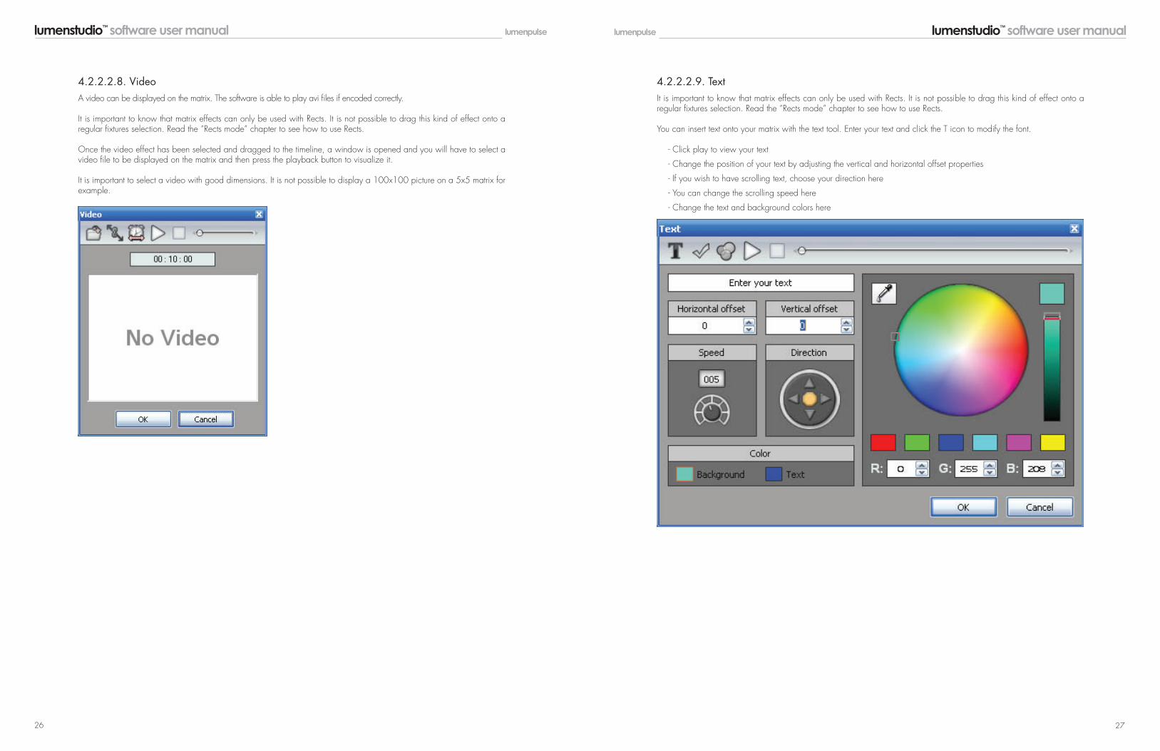
A video can be displayed on the matrix. The software is able to play avi files if encoded correctly.
It is important to know that matrix effects can only be used with Rects. It is not possible to drag this kind of effect onto a regular fixtures selection. Read the “Rects mode” chapter to see how to use Rects.
Once the video effect has been selected and dragged to the timeline, a window is opened and you will have to select a video file to be displayed on the matrix and then press the playback button to visualize it.
It is important to select a video with good dimensions. It is not possible to display a 100x100 picture on a 5x5 matrix for example.
It is important to know that matrix effects can only be used with Rects. It is not possible to drag this kind of effect onto a regular fixtures selection. Read the “Rects mode” chapter to see how to use Rects.
You can insert text onto your matrix with the text tool. Enter your text and click the T icon to modify the font.
- Click play to view your text
- Change the position of your text by adjusting the vertical and horizontal offset properties
- If you wish to have scrolling text, choose your direction here
- You can change the scrolling speed here
- Change the text and background colors here
4.2.2.2.8. Video 4.2.2.2.9. Text

lumenstudio™ software user manual lumenstudio™ software user manual 28 29
Perhaps you have used all of the effects and combined them in every way possible, but you are still looking for something different, perhaps you want to create your own effect from scratch. The color manager allows you to do precisely this.
Draw onto a matrix by selecting a color from the color wheel and clicking the pencil tool. The color manager tool works in a similar way to your standard painting software package, with the ability to fill, draw lines, draw squares and insert images.
- Move your image around the matrix here (1) - Once you are happy with the image, click here (2) to create a new step
When you create a new step, the previous step is copied. Other steps can be copied and pasted here (3). The fade and wait time between each step can be changed by double clicking here (4).
If you are not familiar with “RECTS”, please refer to the Rects Mode topic. When creating effects on a rect timeline, it is possible to add several layers and drag different effects onto each layer.
Click here to add or remove a layer (1)
In the example below, there is a gradient layer with an overlaying text layer. The text is currently blocking the effect. Colors can be made transparent by right clicking the text layer and selecting properties.
- Click here (1) to enable masking
- Select the color you wish to mask (in the example below it is the text background color, blue)
- Adjust the tolerance here (2)
- The opacity of the layer can also be changed
4.2.2.2.10. Color Manager 4.2.2.3. Rect Layers

lumenstudio™ software user manual lumenstudio™ software user manual 30 31
Lumenstudio automatically calculates the RGB or RGBW values required to produce a specific color. However, certain fixtures calculate the RGBW color slightly differently. We can edit the way Lumenstudio calculates the values from the op-tions menu.
By default, the automatic adjustment of the white channel is linear.
LINEAR : If all the Red, Green, and Blue channels are lit to 30%, this 30% will be added by the white channel
SEMI-LINEAR : The white channel will stay at 0 unless there is at least 50% of each color
EXPONENTIAL : The white channel will accelerate as the RGB values are raised. e.g. If the RGB values are at 50%, the white fa der is only at 5%. At 75%, the white fader is at 22%Then in the last 25%, the white fader jumps up to 100%
You can also choose to have manual control of the white color fader if there is a specific color tone you wish to produce from your fixture
- The LIVE tab allows you to test your scenes while programming. Live mode does not serve as a remote control interface for end user use.- Click here (1) to view your fixtures in 3D.
4.2.2.4. RGBW Options V Playing Your Scenes In Live Mode

lumenstudio™ software user manual lumenstudio™ software user manual 32 33
The Lumentouch and Lumencue controllers have an internal clock and calendar with battery backup. This allows you to trigger your scenes by date and time, for a maximum of 40 different calendar triggers. Simply drag your scenes onto the calendar. The example below will trigger scene 1 at 10am on the 26th June. - Note that the controller needs to be ON in order for the triggers to activate.
Double click a trigger to edit. Re-occuring events can be set here. In the example below,our scene is set to be triggered every Saturday in August.
VI Calendar Mode
To begin, before plugging your Lumentouch into your computer be sure that the switch on the bottom marked USB/EXT is switched to USB. Next, plug the USB cable from your laptop/computer to the mini-USB port on the bottom of the Lumen-touch beside the USB/EXT switch.
NOTE: REMOVE PROTECTIVE FILM FROM LUMENTOUCH, this will affect the touch capabilities.
Now you can open Lumenstudio. A dialogue box will pop up. If your Lumentouch device is properly connected, the middle option ‘Click here to work with the USB-DMX interface’ will be available. Choose this option and hit OK.
Lumenstudio will now open with no shows loaded. To load a pre-existing show, choose the File button in the top left corner and choose Open…
VII Uploading a Show - Direct to Device
Connecting the Lumentouch to a Laptop via USB
Setup

lumenstudio™ software user manual lumenstudio™ software user manual 34 35
A dialogue will pop up; here you will go to where your program file is saved. Be sure your file is a .arc file.
Once you have selected the file, click OPEN. The show will then load into the program. Now select the ‘Stand Alone’ tab at the top.
You will want to be sure you are connected to the correct device. If using a Lumencue you want to see SIUDI above the ‘Interface’ type
Now you are ready to assign scenes. (Lumentouch shown from this point forward, Lumencue is similar) You will see on the right hand side the fixtures assigned in this show. On the left side you will see all the scenes created. If you have used AREAS, you will need to click on each area to see the scenes.
For Lumentouch you want to choose STICK:3

lumenstudio™ software user manual lumenstudio™ software user manual 36 37
You will see in the middle, an interactive Lumentouch image. Currently there is no scene assigned. To assign scenes you can drag and drop from the left hand side into the display screen in the center of the device. As soon as you have assigned one scene the image will now show the scene name and the area assigned.
Use the buttons below the display to toggle through the zones (if applicable). Use the left and right arrows to toggle though the assigned scenes.
If multiple zones have been established (10 Max) each must be assigned to an individual page.
Alternately right clicking in the display shows options for assigning/removing scenes, including assign al or remove all .
Deleting or removing a scene here will not delete it from the program, just remove it from the device until it has been as-signed again.
A scene needs to be assigned to the device to function. Once you have assigned all the scenes to the device, you will want to write the show to your Lumentouch.
Choose the Scene button on the interface, and cycle through the Zones and Scenes to see a simulation on the right.
Follow the dialogues as they pop up. The first will ask if you wish to save a copy of the show file to the memory. This will allow you to have a copy of the show on the card, in case you do not have access to it on your computer if you ever want to edit it. Recommended!!
Once you have assigned all the scenes to the buttons, you will want to write the show to your Lumentouch.Select ‘Write the Interface Memory’

lumenstudio™ software user manual lumenstudio™ software user manual 38 39
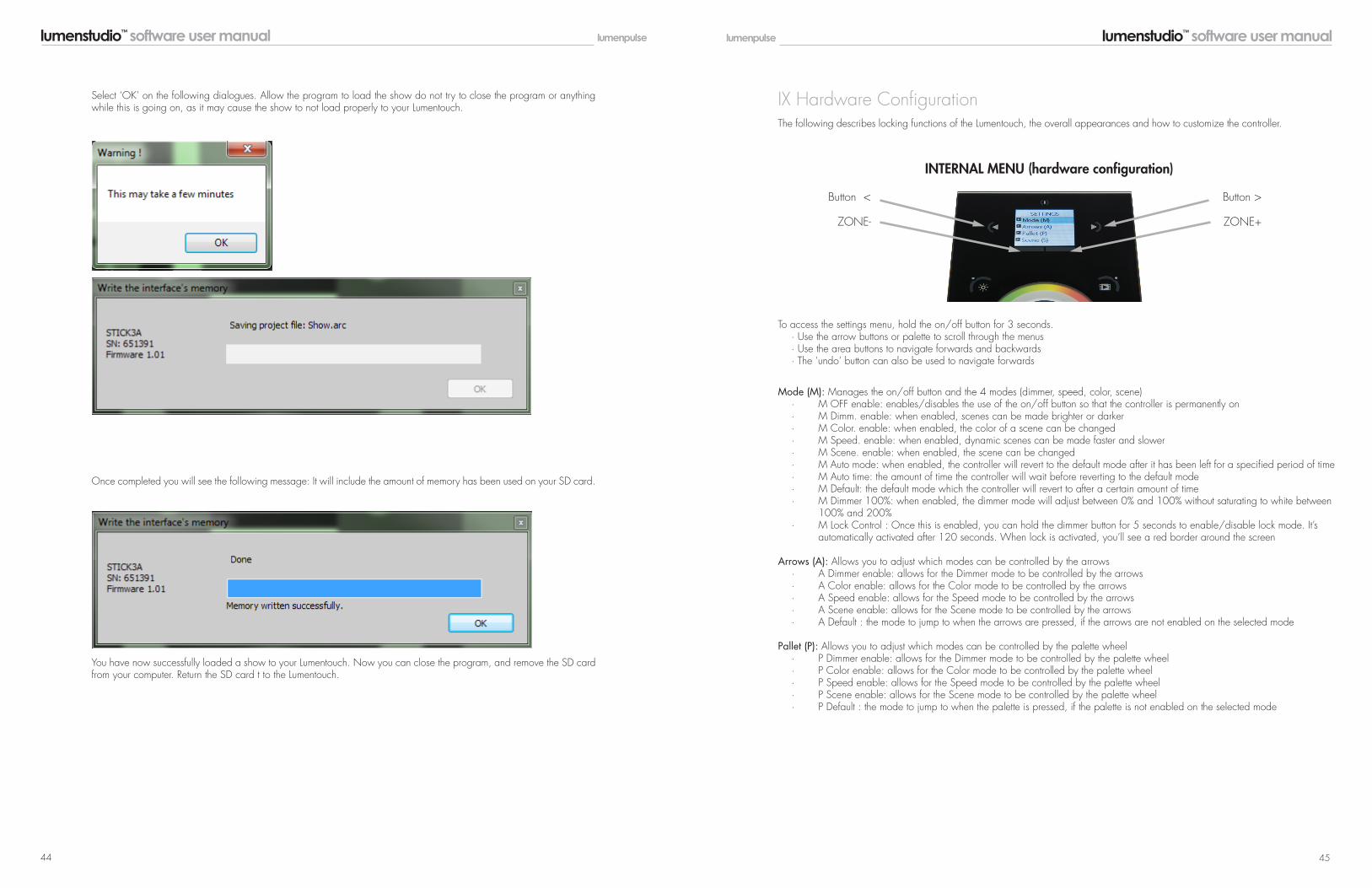
Select ‘OK’ on the following dialogues. Allow the program to load the show do not try to close the program or anything while this is going on, as it may cause the show to not load properly to your Lumentouch.
Once completed you will see the following message: It will include the amount of memory has been used on your SD card.
You have now successfully loaded a show to your Lumentouch. Now you can close the program, and remove the Lu-mentouch from your computer. Be sure to return the USB/EXT switch back to EXT after you have unplugged it from your computer.
VIII Uploading a Show - Direct to SD Card
Open Lumenstudio. A dialogue box will pop up.
Lumenstudio will now open with no shows loaded. To load a pre-existing show, choose the File button in the top left corner and choose Open…
When putting an SD card into the computer, choose ‘Demo Mode’
Setup

lumenstudio™ software user manual lumenstudio™ software user manual 40 41
If trying to edit a show that was successfully saved on SD card, choose SD_CARD (likely the E\: Drive), then folder Show1, then the file Show.arc
A dialogue will pop up; here you will go to where your program file is saved. Be sure your file is a .arc file.
Once you have selected the file, click OPEN. The show will then load into the program. Now select the ‘Stand Alone’ tab at the top.
You will see in the middle, an interactive Lumentouch image. Currently there is no scene assigned. To assign scenes you can drag and drop from the left hand side into the display screen in the center of the device. As soon as you have assigned one scene the image will now show the scene name and the area assigned.
Use the buttons below the display to toggle through the zones (if applicable). Use the left and right arrows to toggle though the assigned scenes.
If multiple zones have been established (10 Max) each must be assigned to an individual page.
Alternately right clicking in the display shows options for assigning/removing scenes.
Deleting or removing a scene here will not delete it from the program, just remove it from the device until it has been as-signed again.
A scene needs to be assigned to the device to function. Once you have assigned all the scenes to the device, you will want to write the show to your Lumentouch.
Choose the Scene button on the interface, and cycle through the Zones and Scenes to see a simulation on the right.

lumenstudio™ software user manual lumenstudio™ software user manual 42 43
Follow the dialogues as they pop up. The first will ask if you wish to save a copy of the show file to the memory. This will allow you to have a copy of the show on the card, in case you do not have access to it on your computer if you ever want to edit it.
Once you have assigned all the scenes to the buttons, you will want to write the show to yourLumentouch. Select ‘Write the Show on Computer’. A dialogue will pop up, save it onto the SDCard. It will overwrite what is on the card. Another dialogue will pop up asking which device typeto save for, choose ‘1024 CHANNELS (STICK)’ for LTO or ‘1024 Channels (SUIDI7) for LCU..
lumenstudio™ software user manual lumenstudio™ software user manual 44 45
Select ‘OK’ on the following dialogues. Allow the program to load the show do not try to close the program or anything while this is going on, as it may cause the show to not load properly to your Lumentouch.
Once completed you will see the following message: It will include the amount of memory has been used on your SD card.
You have now successfully loaded a show to your Lumentouch. Now you can close the program, and remove the SD card from your computer. Return the SD card t to the Lumentouch.
Button <
ZONE-
Button >
ZONE+
INTERNAL MENU (hardware configuration)
Mode (M): Manages the on/off button and the 4 modes (dimmer, speed, color, scene) · M OFF enable: enables/disables the use of the on/off button so that the controller is permanently on · M Dimm. enable: when enabled, scenes can be made brighter or darker · M Color. enable: when enabled, the color of a scene can be changed · M Speed. enable: when enabled, dynamic scenes can be made faster and slower · M Scene. enable: when enabled, the scene can be changed · M Auto mode: when enabled, the controller will revert to the default mode after it has been left for a specified period of time · M Auto time: the amount of time the controller will wait before reverting to the default mode · M Default: the default mode which the controller will revert to after a certain amount of time · M Dimmer 100%: when enabled, the dimmer mode will adjust between 0% and 100% without saturating to white between 100% and 200% · M Lock Control : Once this is enabled, you can hold the dimmer button for 5 seconds to enable/disable lock mode. It’s automatically activated after 120 seconds. When lock is activated, you’ll see a red border around the screen
Arrows (A): Allows you to adjust which modes can be controlled by the arrows · A Dimmer enable: allows for the Dimmer mode to be controlled by the arrows · A Color enable: allows for the Color mode to be controlled by the arrows · A Speed enable: allows for the Speed mode to be controlled by the arrows · A Scene enable: allows for the Scene mode to be controlled by the arrows · A Default : the mode to jump to when the arrows are pressed, if the arrows are not enabled on the selected mode
Pallet (P): Allows you to adjust which modes can be controlled by the palette wheel · P Dimmer enable: allows for the Dimmer mode to be controlled by the palette wheel · P Color enable: allows for the Color mode to be controlled by the palette wheel · P Speed enable: allows for the Speed mode to be controlled by the palette wheel · P Scene enable: allows for the Scene mode to be controlled by the palette wheel · P Default : the mode to jump to when the palette is pressed, if the palette is not enabled on the selected mode
IX Hardware Configuration
To access the settings menu, hold the on/off button for 3 seconds. · Use the arrow buttons or palette to scroll through the menus · Use the area buttons to navigate forwards and backwards · The ‘undo’ button can also be used to navigate forwards
The following describes locking functions of the Lumentouch, the overall appearances and how to customize the controller.

lumenstudio™ software user manual lumenstudio™ software user manual 46 47
Scene (S): Scene management · S 0(off) enable: displays an empty off scene before scene 0 in each area · S Pause enable: allows a scene to be paused if the scene mode button is held for 1 second · S Stop enable: allows a scene to be stopped if the scene mode button is held for 4 seconds · S Fade config : manages the fading between scenes From Show : the fade time set inside the show file will be used Force : the automatic fade time set in the menu will override all fadetimes in the show file Force Max : the controller will look at the show file fade time and the menu fade time and use the greatest Force Min : the controller will look at the show file fade time and the menu fade time and use the smallest Never : the controller will never fade between scenes · S Fade time: the time of the automatic fade between scenes · S Auto reset: when enabled, any color, dimmer or speed overrides will be reset each time the scene is changed · S Trigger : sets the scene triggering mode. Time Delay and Scene Butt allow for scenes to be scrolled through without playing Auto : the scene will be triggered as soon as it’s selected Time Delay : a short delay is added before a scene is triggered Scene Butt. : the selected scene will not play until the scene button is pressed
First Start (F): Default settings when the unit is first powered up · F Scene Nr.: specify a default scene number · F Display Time: when enabled, the time will be displayed on the screen at startup · F Scene Nr.: enables the triggering of a scene at startup. If disabled, no scene will be triggered
Trigger (T): Manages the controllers external triggering properties · T Time enable: enables the clock triggering · T Ports enable: enables the 8 dry contact ports · T RS232 enable: enables scene triggering by RS232 · T IR enable: enables the infra red port (disabled by default to prevent interference) · T UDP enable: allows the controller to send and receive UDP messages required for network control · T Blackout port : enables the blackout relay output which is triggered when the standby button is touched
Ethernet (E): Manages the controllers network settings · Ethernet: Enables the Ethernet socket on the controller · Dynamic IP Addr : enables dynamic IP addressing (DHCP) which allows the controller to obtain an IP address from a router · Sync Blackout: when this open is enabled, all other controllers on the network will go into standby when the standby button is pressed · Enable NTP : enables Network Time Protocol. The controller will synchronise the clock with the internet if a connection is available · NTP Server : the IP address of the server to synchronize the clock. The default is 005.135.141.108 · Device’s IP Add: the controller’s static IP address it will use if it does not receive an IP address via DHCP · Mask: the subnet mask of the controller if not set to DHCP. Generally this is 255.255.255.0 · Default Gateway : the IP address of the router if not set to DHCP · MAC Address : a unique ID used to identify the controller on the network
Date/Time (D): Manages the date and time stored inside the controller · Date: the controller’s date · Time: the controller’s clock time
Graphics (G): Screen management · G Image enable: allows for images to be shown for each scene if they have been assigned in the programming software · G Image full: when enabled, the image will be displayed in full screen and the scene and area will not be visible · G Image time: the time it takes before the image is displayed in full screen · G Sleep enable: when enabled, the screen brightness will dim after a certain amount of time · G Sleep time: the amount of time to wait before sleeping · G Bright normal: the % brightness when the controller is not sleeping · G Bright sleep: the % brightness when the controller is sleeping · G Bright LED: the % brightness of the mode and reset LEDs
DMX Output (X): Manage the timings of the DMX output messages and the page priorities (advanced function!) · X MBB: Mark Before Break- the time to wait between sending each 512 channel DMX message (or ‘packet’) · X Break: Break- the time to wait just before sending a new packet, resetting the DMX line · X MAB: Mark After Break- the message which tells your receiver to begin reading data · X MBS: Mark Between Slots- the delay time between sending each DMX channels data within the DMX packet · Univ-1/Univ-2: each timing can be set differently depending on the universe number · X Alphab Mode: if the same scene is triggered in the global area and a second area, the area with the highest letter will take priority · X LTP Mode: if the same scene is triggered in the global area and a second area, the latest scene triggered takes priority
Sensitive (S): Manage the touch sensitivity settings · S USB Init: reset the touch sensitivity when the USB is connected and disconnected · S Auto Time: the time to wait before automatically resetting the touch sensitivity · S High Sense: when enabled, the sensitivity will be increased · S See Values: see each touch sensitive button number and palette value
Language (L): change the language of the text which appears on the screen
About: Check the firmware release date and version number and assign a name for the controller
Reset: reset all settings to the factory default

lumenstudio™ software user manual lumenstudio™ software user manual 48 49
X Set The Date-Time-Location Settings Via The Menu
- Use the scene buttons (left and right arrows) to scroll through the menus.- Use the area buttons to navigate forwards and backwards.- The fields turn red when they can be edited.
To access the settings menu, hold the standby button for 3 seconds.
Press next scene to scroll down to date/time (D). Press next area to enter the sub menu.
Date (dd-mm-yyyy):Press next area and use the scene buttons to set the correct day.Press next area and use the scene buttons to set the correct month.Press next area and use the scene buttons to set the correct year.Press next area to exit the date setting.
Time (hh:mm:ss):Press next scene to scroll down to the time setting. Press next area and use the scene buttons to set the correct hour.Press next area and use the scene buttons to set the correct minute.Press next area and use the scene buttons to set the correct second.Press next area to exit the time setting.
Country:Press next scene to scroll down to the country name setting.Press next area and use the scene buttons to set the correct country.Press next area to exit the country setting.
City zip:Press next scene to scroll down to the city zip setting.Press next area and use the scene buttons to set the closest city zip.Press next area to exit the city zip setting.
Weekday Winter:Press next scene to scroll down to the weekday winter setting.Press next area and use the scene buttons to set the correct day.Press next area to exit the weekday winter setting.
Month Winter:Press next scene to scroll down to the month winter setting.Press next area and use the scene buttons to set the correct month.Press next area to exit the month winter setting.
Week Number Winter:Press next scene to scroll down to the week number winter setting.Press next area and use the scene buttons to set the correct week.Press next area to exit the week number winter setting.
Weekday Summer:Press next scene to scroll down to the weekday summer setting.Press next area and use the scene buttons to set the correct day.Press next area to exit the weekday summer setting.
Month Summer:Press next scene to scroll down to the month summer setting.Press next area and use the scene buttons to set the correct month.Press next area to exit the month summer setting.
Week Number Summer:Press next scene to scroll down to the week number summer setting.Press next area and use the scene buttons to set the correct week.Press next area to exit the week number summer setting.
Press the standby button to save and exit to normal operation.
XI Service
- Memory card - used to store the scenes- Battery - used to store the clock/calendar- DMX Chips - used to drive the DMX
To replace the Li-Ion rechargeable battery:- You need a rechargeable 3.6v LIR 2032 replacement battery- Remove the back panel by pulling down and sliding it out- Using a paper clip push the battery from the bottom so it slides out of its cage- Slide the replacement battery in from the top, making sure the positive side is facing up- Replace the back panel by pushing it up into place
The firmware can be updated using the Hardware Manager which is available as part of the Lumenstudio Software downloadon the Lumenpulse website: http://www.lumenpulse.com/products/128/lumentouch-20.
Serviceable Parts Include:
Firmware:

© Lumenpulse™ Printed in Canada
2017 / 06
# 116307
Sales Offices and Manufacturing Facilities
Corporate Headquarters
1220 Marie-Victorin Blvd. Longueuil, QC J4G 2H9 Canada
1.877.937.3003 T 514.937.3003 F 514.937.6289
Manchester, UK
4th Avenue, The Village Trafford Park, Manchester M17 1DB UK
T +44 (0) 161 872 6868 F +44 (0) 161 872 6869
Vancouver, Canada
9255 - 194th Street Surrey, BC V4N 4G1 Canada
T 604.549.9379 F 604.549.9555
Florence, Italy
Via della Chiesa, 38 50041 Calenzano (FI) Italy
T +39 055-541754 F +39 055-5417575
Boston, US
10 Post Office Square, Suite 900 Boston, MA 02109 USA
1.877.937.3003 T 617.307.5700 F 617.350.9912
London, UK
The Leathermarket 11/13 Weston Street Unit no 13.3.2, London SE1 3ER UK
T +44 (0) 2031 765370 F +44 (0) 2031 765377 Paris, France
19 Vivienne 75002 Paris France
T +33 (0) 1 40 41 60 10
SE Asia – Partner
25 Tagore Lane, #03-10 Singapore Godown 787602 Singapore
T +65 6305 7680
[email protected] www.lumenpulsegroup.com