ls tractor operator's manual - gml...
TRANSCRIPT

LS T
RA
CT
OR
OPE
RA
TO
R‘S
MA
NU
AL
LS TRACTOR
OPERATOR'S MANUAL
XR
-SE
RIE
S
XR45 XR45HST XR50 XR50HST XR60
P/NO 52113201DATE 20130000
Contents
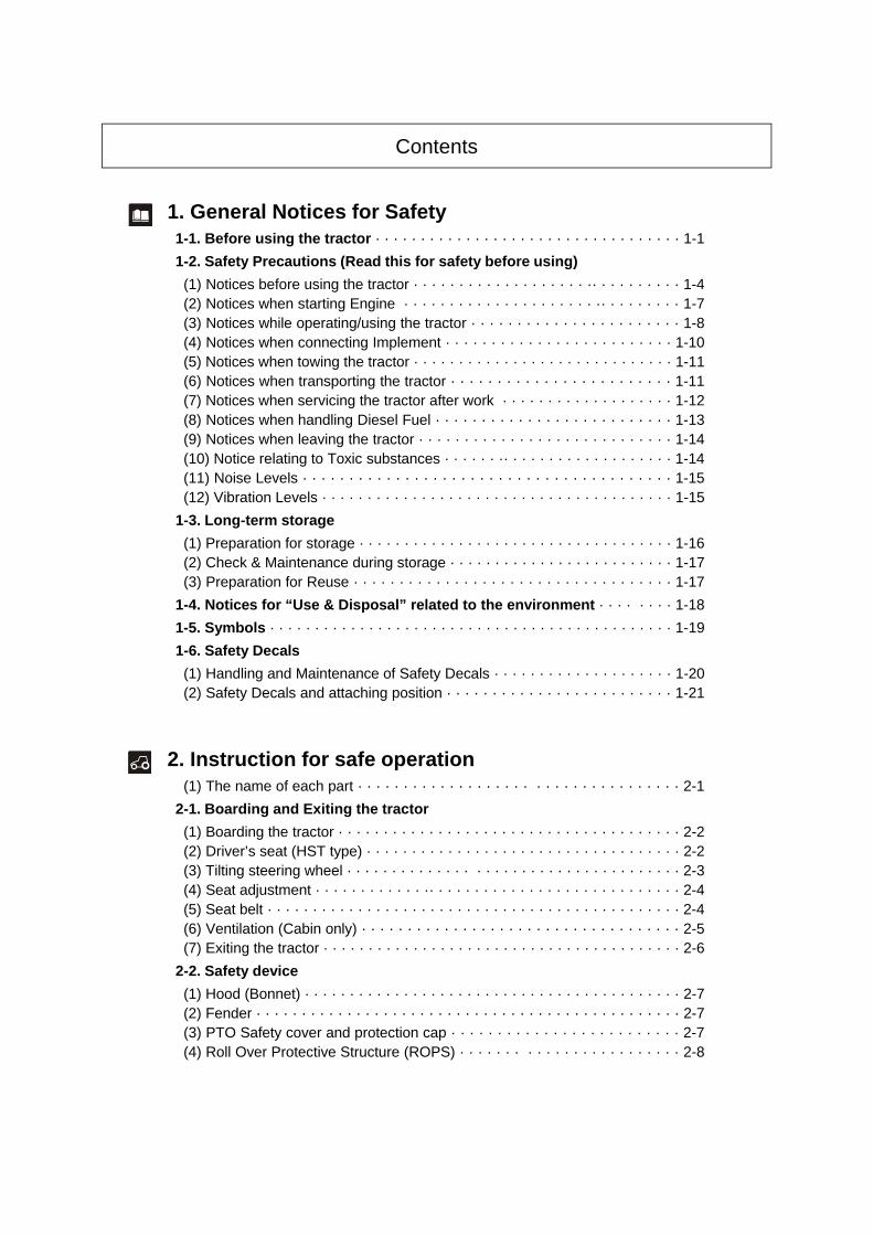
1. General Notices for Safety1-1. Before using the tractor · · · · · · · · · · · · · · · · · · · · · · · · · · · · · · · · · · 1-1
1-2. Safety Precautions (Read this for safety before using)
(1) Notices before using the tractor · · · · · · · · · · · · · · · · · · · ·· · · · · · · · · · 1-4(2) Notices when starting Engine · · · · · · · · · · · · · · · · · · · · · ·· · · · · · · · · 1-7(3) Notices while operating/using the tractor · · · · · · · · · · · · · · · · · · · · · · · 1-8(4) Notices when connecting Implement · · · · · · · · · · · · · · · · · · · · · · · · · 1-10(5) Notices when towing the tractor · · · · · · · · · · · · · · · · · · · · · · · · · · · · · 1-11(6) Notices when transporting the tractor · · · · · · · · · · · · · · · · · · · · · · · · 1-11(7) Notices when servicing the tractor after work · · · · · · · · · · · · · · · · · · · 1-12(8) Notices when handling Diesel Fuel · · · · · · · · · · · · · · · · · · · · · · · · · · 1-13(9) Notices when leaving the tractor · · · · · · · · · · · · · · · · · · · · · · · · · · · · 1-14(10) Notice relating to Toxic substances · · · · · · ·· · · · · · · · · · · · · · · · · · · 1-14(11) Noise Levels · · · · · · · · · · · · · · · · · · · · · · · · · · · · · · · · · · · · · · · · 1-15(12) Vibration Levels · · · · · · · · · · · · · · · · · · · · · · · · · · · · · · · · · · · · · · · 1-15
1-3. Long-term storage
(1) Preparation for storage · · · · · · · · · · · · · · · · · · · · · · · · · · · · · · · · · · · 1-16(2) Check & Maintenance during storage · · · · · · · · · · · · · · · · · · · · · · · · · 1-17(3) Preparation for Reuse · · · · · · · · · · · · · · · · · · · · · · · · · · · · · · · · · · · 1-17
1-4. Notices for “Use & Disposal” related to the environment · · · · · · · · 1-18
1-5. Symbols · · · · · · · · · · · · · · · · · · · · · · · · · · · · · · · · · · · · · · · · · · · · · 1-19
1-6. Safety Decals
(1) Handling and Maintenance of Safety Decals · · · · · · · · · · · · · · · · · · · · 1-20(2) Safety Decals and attaching position · · · · · · · · · · · · · · · · · · · · · · · · · 1-21
2. Instruction for safe operation(1) The name of each part · · · · · · · · · · · · · · · · · · · · · · · · · · · · · · · · · · · 2-1
2-1. Boarding and Exiting the tractor
(1) Boarding the tractor · · · · · · · · · · · · · · · · · · · · · · · · · · · · · · · · · · · · · · 2-2(2) Driver’s seat (HST type) · · · · · · · · · · · · · · · · · · · · · · · · · · · · · · · · · · · 2-2(3) Tilting steering wheel · · · · · · · · · · · · · · · · · · · · · · · · · · · · · · · · · · · · · 2-3(4) Seat adjustment · · · · · · · · · · · · ·· · · · · · · · · · · · · · · · · · · · · · · · · · · · 2-4(5) Seat belt · · · · · · · · · · · · · · · · · · · · · · · · · · · · · · · · · · · · · · · · · · · · · · 2-4(6) Ventilation (Cabin only) · · · · · · · · · · · · · · · · · · · · · · · · · · · · · · · · · · · 2-5(7) Exiting the tractor · · · · · · · · · · · · · · · · · · · · · · · · · · · · · · · · · · · · · · · · 2-6
2-2. Safety device
(1) Hood (Bonnet) · · · · · · · · · · · · · · · · · · · · · · · · · · · · · · · · · · · · · · · · · · 2-7(2) Fender · · · · · · · · · · · · · · · · · · · · · · · · · · · · · · · · · · · · · · · · · · · · · · · 2-7(3) PTO Safety cover and protection cap · · · · · · · · · · · · · · · · · · · · · · · · · 2-7(4) Roll Over Protective Structure (ROPS) · · · · · · · · · · · · · · · · · · · · · · · · 2-8
CONTENTS
3. Instruments and Controls3-1. Instrument Panel and Front controls
(1) Instrument panel · · · · · · · · · · · · · · · · · · · · · · · · · · · · · · · · · · · · · · · · 3-3(2) Key switch · · · · · · · · · · · · · · · · · · · · · · · · · · · · · · · · · · · · · · · · · · · · 3-6(3) Turn signal light switch · · · · · · · · · · · · · · · · · · · · · · · · · · · · · · · · · · · · 3-6(4) Light switch · · · · · · · · · · · · · · · · · · · · · · · · · · · · · · · · · · · · · · · · · · · · 3-6(5) Horn switch · · · · · · · · · · · · · · · · · · · · · · · · · · · · · · · · · · · · · · · · · · · · 3-7(6) Hazard warning light switch · · · · · · · · · · · · · · · · · · · · · · · ·· · · · · · · · · 3-7(7) Grille work light switch · · · · · · · · · · · · · · · · · · · · · · · · · · · ·· · · · · · · · 3-7(8) Beacon lamp switch (if fitted) · · · · · · · · · · · · · · · · · · · · · · · ·· · · · · · · · 3-8(9) Cruise control switch (HST type) · · · · · · · · · · · · · · · · · · · · ·· · · · · · · · 3-8(10) PTO switch · · · · · · · · · · · · · · · · · · · · · · · · · · · · · · · · · · · · · · · · · · · 3-9(11) PTO mode switch (if fitted) · · · · · · · · · · · · · · · · · · · · · · · · · · · · · · · · 3-9(12) Shuttle lever (Mechanical) · · · · · · · · · · · · · · · · · · · · · · · · · · · · · · · · 3-10(13) Throttle lever · · · · · · · · · · · · · · · · · · · · · · · · · · · · · · · · · · · · · · · · · 3-10(14) Throttle pedal (Mechanical) · · · · · · · · · · · · · · · · · · · · · · · · · · · · · · 3-10(15) Clutch pedal (Mechanical) · · · · · · · · · · · · · · · · · · · · · · · · · · · · · · · · 3-11(16) Brake pedals · · · · · · · · · · · · · · · · · · · · · · · · · · · · · · · · · · · · · · · · · 3-11(17) HST forward/reverse pedal (HST type) · · · · · · · · · · · · · · ·· · · · · · · · 3-12(18) Creeper lever (MEC, if fitted) · · · · · · · · · · · · · · · · · · · · · · · · · · · · · · 3-12
3-2. Right-hand controls and Cabin pillar
(1) Main gear shift lever (Mechanical) · · · · · · · · · · · · · · · · · · · · · · · · · · · 3-13(2) Range gear shift lever (HST type) · · · · · · · · · · · · · · · · · · · · · · · · · · · 3-14(3) Parking brake lever · · · · · · · · · · · · · · · · · · · · · · · · · · · · ·· · · · · · · · · 3-15(4) Differential lock pedal · · · · · · · · · · · · · · · · · · · · · · · · · · · · · · · · · · · · 3-15(5) Work light switch · · · · · · · · · · · · · · · · · · · · · · · · · · · · · · · · · · · · · · · 3-16(6) Window wiper switch (Front, Rear) · · · · · · · · · · · · · · · · · · · · · · · · · · 3-16(7) Electrical power outlet socket (cabin only) · · · · · · · · · · · · · · · · · · · · · 3-17(8) Indoor light (Cabin only) · · · · · · · · · · · · · · · · · · · · · · · · · · · · · · · · · · 3-17(9) Audio player (Cabin only) (if fitted) · · · · · · · · · · · · · · · · · · · · · · · · · · · 3-17
3-3. Left-hand controls
(1) Range gear shift lever (Mechanical only) · · · · · · · · · · · · · · · · · · · · · · 3-19(2) PTO gear lever (if fitted) · · · · · · · · · · · · · · · · · · · · · · · · · · · · · · · · · 3-19(3) Four wheel drive lever (4WD) · · · · · · · · · · · · · · · · · · · · · · · · · · · · · · 3-20(4) GSP lever (if fitted) · · · · · · · · · · · · · · · · · · · · · · · · · · · · · · · · · · · · · 3-20(5) Middle PTO lever (if fitted) · · · · · · · · · · · · · · · · · · · · · · · · · · · · · · · 3-20
3-4. Hydraulic system
(1) Safety precautions · · · · · · · · · · · · · · · · · · · · · · · · · · · · · ·· · · · · · · · 3-21(2) Steering system · · · · · · · · · · · · · · · · · · · · · · · · · · · · · · · ·· · · · · · · · 3-22(3) Hydraulic lift Control (MHL) · · · · · · · · · · · · · · · · · · · · · · · · · · · · · · · 3-22(4) Remote control lever and Quick coupler (optional) · · · · · · · · · · · · · · · 3-24(5) Joystick lever (optional) · · · · · · · · · · · · · · · · · · · · · · · · · · · · · · · · · · 3-25(6) Hydraulic System Diagram · · · · · · · · · · · · · · · · · · · · · · · · · ·· · · · · · 3-26

CONTENTS
4. Operation and Work4-1. Engine start and stop
(1) Engine start · · · · · · · · · · · · · · · · · · · · · · · · · · · · · · · · · · · · · · · · · · · · 4-1(2) Start in cold weather · · · · · · · · · · · · · · · · · · · · · · · · · · · · · · · · · ·· · · · 4-3(3) Engine stop · · · · · · · · · · · · · · · · · · · · · · · · · · · · · · · · · · · · · · · · · · · 4-3
4-2. How to Drive and how to Stop
(1) How to drive · · · · · · · · · · · · · · · · · · · · · · · · · · · · · · · · · · · · · · · · · · · 4-4(2) Changing speed · · · · · · · · · · · · · · · · · · · · · · · · · · · · · · · · · · · · · · · · 4-6(3) Emergency Stop · · · · · · · · · · · · · · · · · · · · · · · · · · · · · · · · · · · · · · · · 4-7(4) Stopping tractor · · · · · · · · · · · · · · · · · · · · · · · · · · · · · · · · · · · · · · · · · 4-8(5) Driving tractor on the road · · · · · · · · · · · · · · · · · · · · · · · · · · · · · · · · 4-9(6) Parking · · · · · · · · · · · · · · · · · · · · · · · · · · · · · · · · · · · · · · · · · · · · · · 4-10(7) Handling Turbocharger (if fitted) · · · · · · · · · · · · · · · · · · · · · · · · · · · · 4-10
4-3. How to handle new tractor
(1) Check points · · · · · · · · · · · · · · · · · · · · · · · · · · · · · · · · · · · · · · · · · · 4-11(2) Notices in handling new Tractor · · · · · · · · · · · · · · · · · · · · · · · · · · · · · 4-11
4-4. Attaching Implement
(1) 3-point linkage · · · · · · · · · · · · · · · · · · · · · · · · · · · · · · · · · · · · · · · · · 4-12(2) Power take-off (PTO) shaft · · · · · · · · · · · · · · · · · · · · · · · · · · · · · · · · 4-16(3) Hitch and Drawbar (optional) · · · · · · · · · · · · · · · · · · · · · ·· · · · · · · · · 4-18(4) 7-Pole connector (optional) · · · · · · · · · · · · · · · · · · · · · · · · · · · · · · · · 4-19(5) Technically maximum permissible mass · · · · · · · · · · · · · · · · · · · · · · · 4-20(6) Tires and Load capacity · · · · · · · · · · · · · · · · · · · · · · · · · · · · · · · · · · 4-21(7) Adjusting Wheel tracks and tire replacement · · · · · · · · · · · · · · · · · · · · 4-22(8) Using Front-end loader (optional) · · · · · · · · · · · · · · · · · · · · · · · · · · · · 4-25(9) Adjusting Steering angle · · · · · · · · · · · · · · · · · · · · · · · · · · · · · · · · · · 4-27(10) Recommended maximum specification of implements · · · · · · · · · · · · 4-28
4-5. Working in hazardous area · · · · · · · · · · · · · · · · · · · · · · · · · · · · · · 4-29
4-6. Driving Speed· · · · · · · · · · · · · · · · · · · · · · · · · · · · · · · · · · · · · · · · · 4-30

CONTENTS
5. Lubrication and Maintenance5-1. Access for maintenance · · · · · · · · · · · · · · · · · · · · · · · · · · · · · · · · · · 5-1
5-2. Maintenance chart · · · · · · · · · · · · · · · · · · · · · · · · · · · · · · · · · · · · · · 5-2
5-3. Lubricants and Capacity · · · · · · · · · · · · · · · · · · · · · · · · · · · · · · · · · 5-6
5-4. First 50 hour check · · · · · · · · · · · · · · · · · · · · · · · · · · · · · · · · · · · · · 5-7
5-5. When the warning indicator lights
(1) Drain water from Fuel filter · · · · · · · · · · · · · · · · · · · · · · · · · · · · · · · · · 5-8
5-6. Check before starting (Daily check)
(1) Engine oil · · · · · · · · · · · · · · · · · · · · · · · · · · · · · · · · · · · · · · · · · · · · · 5-9(2) Fuel tank · · · · · · · · · · · · · · · · · · · · · · · · · · · · · · · · · · · · · · · · · · · · · 5-10(3) Instrument panel & Indicators · · · · · · · · · · · · · · ·· · · · · · · · · · · · · · · · 5-10(4) Turn signal lights, Lights and Horn · · · · · · · · · · · · · · · · · · · · · · · · · · 5-11(5) Engine coolant · · · · · · · · · · · · · · · · · · · · · · · · · · · · · · · · · · · · · · · · · 5-12(6) Air cleaner (Dry type) · · · · · · · · · · · · · · · · · · · · · · · · · · · · · · · · · · · · 5-12(7) Cleaning of Radiator and Radiator screen · · · · · · · · · · · · · · · · · · · · · 5-13(8) Tire air pressure damage · · · · · · · · · · · · · · · · · ·· · · · · · · · · · · · · · · · 5-13(9) Tightening state of bolt and nut of each part · · · · · · · · · · · · · · · · · · · · 5-14(10) Adjustment of Clutch pedal play (Mechanical type) · · · · · · · · · · · · · · 5-14(11) Adjustment of brake pedal play · · · · · · · · · · · · · · · · · · · · · · · · · · · · 5-14(12) Adjusting HST control linkage (HST type) · · · · · · · · · · · · · · · · · · · · · 5-15
5-7. Every 50 hour check
(1) Lubricating grease nipple · · · · · · · · · · · · · · · · · · · · · · · · · · · · · · · · · 5-16(2) Cleaning of Radiator and Radiator screen · · · · · · · · · · · · · · · · · · · · · 5-16(3) Checking Transmission oil · · · · · · · · · · · · · · · · · · · · · · · · · · · · · · · · 5-17(4) Checking Front axle oil · · · · · · · · · · · · · · · · · · · · · · · · · · · · · · · · · · 5-17(5) Battery check · · · · · · · · · · · · · · · · · · · · · · · · · · · · · · · · · · · · · · · · · 5-17(6) Air cleaner (Dry type) · · · · · · · · · · · · · · · · · · · · · · · · · · · · · · · · · · · · 5-17(7) Hydraulic hoses and Leakage · · · · · · · · · · · · · · · · · · · · · · · · · · · · · · 5-17(8) Cleaning Cabin air filters · · · · · · · · · · · · · · · · · · · · ·· · · · · · · · · · · · · 5-18
5-8. Every 300 hour check
(1) Replacing Engine oil and Filter · · · · · · · · · · · · · · · · · · · · · · · · · · · · · 5-19(2) Replacing Hydraulic oil filter · · · · · · · · · · · · · · · · · · · · · · · · · · · · · · · 5-20(3) Tension adjustment of Engine belt · · · · · · · · · · · · · · ·· · · · · · · · · · · · 5-21(4) Replacing Air cleaner element (Dry type) · · · · · · · · · · · · · · · · · · · · · · 5-22(5) Toe-in · · · · · · · · · · · · · · · · · · · · · · · · · · · · · · · · · · · · · · · · · · · · · · · 5-22
5-9. Every 600 hour check
(1) Changing Front axle oil · · · · · · · · · · · · · · · · · · · · · · · · · · · · · · · · · · · 5-23(2) Changing Transmission oil · · · · · · · · · · · · · · · · · · · ·· · · · · · · · · · · · · 5-23(3) Replacing Fuel filter cartridge · · · · · · · · · · · · · · · · · ·· · · · · · · · · · · · · 5-24(4) Adjusting Engine valve clearance · · · · · · · · · · · · · · · · · · · · · · · · · · · 5-24(5) Checking Nozzle injection pressure · · · · · · · · · · · · · · · · · · · · · · · · · · 5-24(6) Replacing Cabin air filters · · · · · · · · · · · · · · · · · · · · · · · · · · · · · · · · · 5-25

CONTENTS
5-10. Every 2-year check
(1) Replacement of Engine coolant · · · · · · · · · · · · · · · · · · · · · · · · · · · · · 5-26
5-11. General maintenance (When required)
(1) Air-bleeding from Fuel system · · · · · · · · · · · · · · · · · · · · · · · · · · · · · · 5-27(2) Fuse & Main fuse · · · · · · · · · · · · · · · · · · · · · · · · · · · · · · · · · · · · · · · 5-29(3) Battery handling and Notices · · · · · · · · · · · · · · · · · · · · · · · · · · · · · · · 5-30
5-12. Troubleshooting · · · · · · · · · · · · · · · · · · · · · · · · · · · · · · · · · · · · · 5-34
6. Air conditioning System6-1. The name of each part of cooling and heating system · · · · ·· · · · · · · 6-1
6-2. How to use air conditioner and heater
(1) How to operate air conditioner and heater · · · · · · · · · · · · · · · ·· · · · · · · 6-2(2) Air direction control · · · · · · · · · · · · · · · · · · · · · · · · · · · · · · · ·· · · · · · · 6-2
6-3. Every 6 month check
(1) Checking refrigerant amount · · · · · · · · · · · · · · · · · · · · · · · · · · · · · · · · 6-3(2) Cleaning condenser and Radiator screen · · · · · · · · · · · · · · · · · · · · · · 6-3(3) Checking leakage · · · · · · · · · · · · · · · · · · · · · · · · · · · · · · · · · · · · · · · 6-3(4) Belt tension adjustment · · · · · · · · · · · · · · · · · · · · · · · · · · · · · · · · · · · 6-3
6-4. Every year check
(1) Compressor check · · · · · · · · · · · · · · · · · · · · · · · · · · · · · · · · · · · · · · · 6-4(2) Control switch check · · · · · · · · · · · · · · · · · · · · · · · · · · · · · · · · · · · · · 6-4
6-5. Troubleshooting · · · · · · · · · · · · · · · · · · · · · · · · · · · · · · · · · · · · · · · 6-5
6-6. System diagram · · · · · · · · · · · · · · · · · · · · · · · · · · · · · · · · · · · · · · · · 6-7
7. Dimension & Specification · · · · · · · · · · · · · · · · · · · · · · · · · 7-1

1 - 1
1. General Notices for Safety1-1. Before using the tractor
※ Have to read and understand this Operator’s manual carefully and always refer to information and prescriptions outlined in this manual to prevent all potential health and safety risks.
◆ General information for intended use
Your tractor is designed and manufactured to pull, to carry, to supply the power a variety of mounted
or towed equipment for agriculture. Do not use the product for other purposes than intended by the
manufacturer and outlined in this manual. Do not use this tractor for light/heavy forestry applications.
Do not use the product beyond its limits of terrain gradient and stability than outlined in this manual.
Using the tractor beyond these limits may cause a overturning accident.
Do not use the tractor on higher speeds than allowed by the load of the tractor and road condition.
Always choice a suitable driving speed to maintain the stability of the tractor.
Do not use the tractor near or on soft verges of canals and brooks or banks and verges that are
undermined by rodents. The tractor may sink sideways and roll-over.
Do not use the tractor on brittle bridge heads and poor bridge floors, These constructions may
collapse and cause overturning of the tractor. Always check out the condition and carrying
capacity of bridges and ramps prior to engage.
Do not use the tractor without wearing the seat belt and Roll-Over Protective Structure (ROPS)
during operations where roll-over or tip-over hazards exist. The ROPS will only be fully effective when
the driver remains attached to his seat.
Do not use equipment mounted on the tractor which is not correctly matching and firmly fixed.
Such equipment may increase the risk for roll-over and hit the tractor when coming loose.
Do not use the tractor in combination with equipment arbitrary, without having consulted the
specific operator’s manual provided with the equipment. This manual alone cannot provide you
with all the information about safety operation of the combination.
Do not use the tractor beyond its limits of dynamic stability. High speed, abrupt maneuvers, and
fast and short cornering will increase the risk of roll-over.
Do not use the tractor for overloaded pulling work, in cases where you don’t know if the load will
yield, for instance when pulling stumps. The tractor may flip over when the stump is not yielding.
Be extremely cautious when working with the tractor on forage silos without lateral concrete walls.
A wide track setting may improve the lateral stability of the tractor.
Be cautious that the center of gravity of the tractor may increase when the front-end loader is
loaded or the three-point linkage are raised. In these conditions, the tractor may roll-over earlier than
expected.
Do not step down from the tractor without shutting down the PTO, shifting the transmission
to neutral and applying the parking brake.

1 - 2
◆ Safety Mark Description
- In the places where the cautions in usage are required, the marks such as “DANGER”, “WARNING”,
“CAUTION” are found.
- You should comply with the description marked on the decals attached on the product or the contents
marked with safety mark in this Operator's Manual..
Warning – This indicates a potential dangerous situation that may cause a serious
injury or death if not avoided.
Caution – This indicates a potential dangerous situation that may cause a light
injury or damage to the properties if not avoided.
Notice – This indicates the instructions for right use for the safety of persons or
products.
Danger – This indicates a fatal dangerous situation that may cause a serious injury
or death if not avoided.
Notice
Caution
Warning
Danger
Never remove or modify or change the driver’s protection device or safety device arbitrary.
You must take the necessary precautions to always be aware of the possible presence of bystanders, certainly when maneuvering in confined areas. Keep people away from the tractor during work. Pay the necessary attention while operating next to public roads or footpaths. Thrown objects can get projected outside the field and hit unprotected people like bikers or pedestrians. Wait until it is clear of bystanders.
Do not violate the local traffic rules related to public roads and highways
Do not allow riders on the tractor; do not allow people standing on the access way or step to the cab when the tractor is moving. Your view to the left will be obstructed and a rider risks to fall from the tractor during unforeseen or abrupt movements.
This tractor has only one operator station and is a one man operated vehicle. Other people on or around the tractor during normal operation are not allowed.
Always stay clear from implements operating area and especially do not stand between tractor and trailed vehicle either three-point linkage when operating lift controls; ensure no bystanders are near these operating areas.
This tractor may be equipped with a number of sensors to control safety functions. Do not attempt to bypass any function on the tractor. You will be exposed to serious hazards, and moreover, the behavior of the tractor may become unpredictable.
The manufacturer will not be responsible for the damage or safety problems caused by maintenance
or repair with non-genuine parts. It must be requested to use the genuine parts.
When cleaning the tractor by using high pressurized water, do not inject water directly to the
electronic parts, wiring, air intake pipe, hot engine or muffler inside the bonnet.
Maintenance and repair of the tractor is performed by skilled technical experts with the proper
tools authorized by the manufacturer.
For damage or accidents caused by the miss use or operation in violation of these rules, the
manufacturer and its distributors will not have any responsibility and warranty.
Keep this Operator’s manual for future reference at hand (on the tractor).

1 - 3
◆ Terminology
When reading this Operator's Manual, refer to
the right figure for the discrimination of the front/
rear/ left/ right direction.
Front
Rear
RightLeft
Fig.1-1
◆ Product Identification
Your tractor has a exclusive chassis number and
engine number marked with product serial number
tag to identify the product. (See Fig.1-1)
In case of requesting service or parts from your
dealer
Dealer will need chassis serial number, engine
serial number, TM number, and also running hours
displayed on the instrument panel. (See Fig. 1-3)
Chassis No.
Fig.1-2
Engine No.
Fig.1-3
Hour meter
Fig.1-4
TM number

1 - 4
1-2. Safety Precautions - read this for safety before using.
(1) Notices before using the tractor For Safety Instruction : Before using the tractor,
read this Operator's Manual carefully and
understand the instructions fully for the safety
prevention and right usage of the tractor and then
use the tractor safely according to the instructions.
Read Operator’sManual.
▶Additional seat (where fitted) is used for driver training or instruction. Do not permit
anyone to ride on the tractor.Warning
Operator’s condition : The persons such as
patients, drunks, people on drugs, etc. are never
allowed to operate this tractor.
Only educated operators can use the tractor after
learning the usage of controls for moving, stopping,
turning and other operating.
Suitable Clothes & Protect Entanglement :
When checking or operating the tractor, wear tight
fitting clothes and safety equipment instead of
loose or long clothes. Also, slippers, high heel
shoes are not suitable for operation. Wear the low
shoes or work shoes or boots.
Warning ▶Do not approach the rotating shaft such as PTO shaft or cooling fan, especially,
with loose clothing and long clothes. The entanglement in rotating shaft can cause
serious injury or death.
▶Stop the engine and be sure PTO shaft is stopped before getting near it.
Keep Riders off : Riders on the tractor or implements obstruct the operator’s view and can be
thrown off the tractor. It can cause a serious injury or death. Riders should not be carried on the
tractor at any time.
Safety Decals : For right use and personal safety of the operator, the safety decals are attached to
the parts related with safety operation. Before using the tractor, comply with the safety instructions.
(For further information, refer to “1-6 Safety Decals”, See page 1-20)
Especially, special cares must be taken for using the tractor in the places where the safety
signs such as Danger, Warning, Caution etc. are marked. (See page 1-2)

1 - 5
Protect Children : Pay special attention to children (or a child) while using the tractor or during
storage.
- Make sure children keep a safe distance from the tractor and all implements before using the
tractor. Be alert to the presence of children.
- Do not let children or an untrained person operate the tractor.
- Do not allow children to approach the tractor while the engine is running.
- When parking the tractor, remove the ignition key and lower implements to the ground for
children’s safety.
▶As children are very curious, they may do unexpected movements or actions.
Special care must be taken, when operating tractor or equipment. Warning
Periodical Check : “Lubrication and Maintenance” must be performed periodically. If necessary,
do it immediately and if not, it may cause the failure, reduction of product life or physical injury.
* Periodic Lubrication and Maintenance
Fuel, Oil, Filter, Air cleaner, Battery, Belt, Cable, Grease, Pedals such as clutch and brake pedal,
Tire air pressure, Wheel bolts, Toe-in, Electrical wirings, other items related to safety.
Genuine Parts : When replacing parts, you must use “Genuine Parts” of LS tractor. Contact your
authorized dealer. If not, it may cause a reduction of product life, failure and serious injury.
Restrict Maintenance : If you repair or change some components and settings arbitrary, the
performance of the tractor can NOT be guaranteed, and may void the warranty And also,
maintenance of the heavy weighted parts without special tools can cause serious injury.
If it is required to check or repair the tractor due to trouble, or if you have any questions for the
usage or operation of the tractor, contact your authorized dealer.
* The items that are not allowed to be modified or changed or removed arbitrarily by user are
below :
- Protection structures such as PTO cover, Guards, Safety frame (Roll-bar), Cab, etc.
- Engine components, Fuel injection control and setting, etc.
- Automatic control equipment, Lamps, Transmission, Hydraulic valve and pressure settings.
- Other parts that detail and where complicated adjustments are needed.
▶ Skilled professional technology is needed for the repair.
▶ For derail maintenance or repair, contact your authorized dealer.Warning
Lamps : Do not modify the lamps or change the bulb capacity arbitrarily.
▶ Modified lamps or change bulb capacity may cause the traffic accident by
disturbing approaching driver’s views.
▶ If the lamp is blown out, replace it immediately with a genuine part. In case of
driving at night, it may cause a traffic accident.
Warning

1 - 6
Protective Structures : For the operator’s safety, various protective structures, i.e. Bonnet (Hood),
Fan cover, PTO safety cover, PTO shaft protection cap, Roll-bar or another Roll-over Protective
Structure, etc are attached on the tractor. If these structures are modified or removed by user
arbitrarily, it may cause serious accident. Such behaviors are prohibited strictly.
▶ The Protective Structure and interconnecting components are a certified system.
Any damage, Fire, corrosion or modification will weaken the structure and reduce
your protection. If this occurs, the Protective Structure MUST be replaced with a
new one. Contact your authorized dealer for Protective Structure inspection and
replacement.
▶ In case of an accident, fire, tip or roll-over, the following MUST be performed by a
qualified technician before operating the tractor again.
- The Protective Structure MUST be replaced.
- The mounting or suspension for the Protective Structure , operator seat and
suspension, seat belt and mounting components and wiring within the operator’s
protective system MUST be carefully inspected for damage.
- All damaged parts MUST be replaced.
▶ DO NOT attach any device to the Protective Structure for pulling purposes.
▶ DO NOT weld, drill holes, attempt to straighten or repair the protective
structure. The modification can reduce the structural integrity of the
structure which can cause death or serious injury in the event of fire, tip, roll
over, collision or accident and void the warranty.
Warning
Level of protection of the FOPS (Falling Objects Protective Structure) :
- For cabin model, it provides protection against falling objects according to OECD code 10
standard. The energy level of drop test is 1365 J. But it does not mean that the cabin provide full
protection against all the falling objects in the work field.
- For roll-bar model, it does NOT any protection against falling objects. It is recommended to use a
certified FOPS structure when working with front-end loaders.
Level of protection against hazardous substances :
- For cabin model of this tractor, it provides protection against hazardous substances according to
EN15695-1:2009 (Category 2). But it can provide only dust protection level by pressurizing air
in the cabin with air filters, Do not use the tractor with crop sprayers in chemical hazardous area.
Level of protection of the OPS (Operators Protection Structure) : This tractor does NOT
provide protection against
- low hanging wires and branches in the forest, orchard or construction area, etc
- toppling trees, primarily in case a rear-mounted tree grab-crane is mounted at the rear of the
tractor
- penetrating objects in the operator’s enclosure, primarily in case a winch is mounted at the rear of
the tractor.
- potential risks by using any optional equipment that might be available to deal with those hazards.
NEVER enter or operate these hazardous area without certified Operator Protective Structure
installed.

1 - 7
(2) Notices when starting Engine
Check each part with reference of “5. Lubrication
and Maintenance” in this manual. If necessary,
repair or replace it immediately. Especially,
check if safety protection structures or covers
are attached originally and the bolts and nuts
are tightened well.
Before starting, check again if there are other
workers or children around the tractor and
implements and keep a safe distance.
Start engine and operate the tractor after sitting
on the driver’s seat correctly with seat belt
fastened.
Place the shuttle lever, transmission gear lever in
NEUTRAL and especially check if parking brake
is applied.
Lower the implements on the ground.
Ensure that rear view mirrors and the other
mirrors (if fitted) are adjusted correctly, and check
the operation of the headlights and other lights
Put PTO switch to OFF position. If the PTO switch
is ON position, the engine can NOT be started.
(See Fig.1-5 )
Depress the clutch pedal fully (if fitted). If not, the
start safety switch does not contacted enough and
the engine can NOT start.
Warning
▶Do not start the engine in a closed area. The poisonous exhaust gas can cause
fatal damage to the driver or persons around.
Fig.1-5
PTO switch
ON : PUSH AND TURNOFF : PUSH
PTO switch

1 - 8
Connect left and right brake pedals while driving
on the road. (if fitted)
DO NOT use differential lock device while driving
on the road or turning in the field.
DO NOT ride your foot on the brake pedal or
clutch pedal.
Lower the driving speed enough before turning a
sharp curve. Especially, when you drive the tractor
with implements, make the turning radius wider.
DO NOT start or stop the tractor suddenly. Engage
the clutch and brake softly. If not, front wheels can
be lifted up and it is very dangerous.
Do not jump up and down while tractor is moving.
When getting off or on the tractor, use the grip or
handrail and sub step to prevent falls.
(3) Notices while operating/using the tractor
Ventilation
Warning▶It is very dangerous to work in
a closed area. The poisonous
exhaust gas may cause serious
damage to the human body. If
you should work in this area,
make sure to ventilate well and
put on the protective mask.
When driving the tractor in reverse, lower the
engine speed. Make sure to check if there is any
obstacle or person in the rear.
DO NOT permit other people and especially
children approach within working area while
operating tractor and equipment.
Noise and Vibration : When working between buildings or in confined spaces, the sound pressure
level can be increased. Wear suitable ear protectors in high noise level conditions. When working
with equipment in the field, Vibration may intensity from the equipment may be increased. To reduce
the harm to the body, take a rest periodically.

1 - 9
When working at the edge of steep slope, take
special care about a turn-over.
When working, wear the protection equipment
and tighten the seat belt.
If the authorized passenger seat are not installed,
keep riders off.
On a downhill, operate the throttle pedal and
brake pedal slowly and DO NOT drive while the
transmission gear is in NEUTRAL.
To climb a steep slope, drive tractor slowly in
reverse up the slope rather than forward. It is
much safer.
When turning the tractor on a slope, pay
attention to safety especially.
When crossing a high ridge, let down the
implement and go straight across the ridge at
low speed.
When connecting the implements to the
front/rear of the tractor, install the proper
additional weights in the rear/front of the tractor
to keep the balance of the tractor.
Obey the traffic rules while driving on public roads.
Do not exceed the local legal speed limit.
Use a sing beacon or slow moving vehicle (SMV)
to indicate that the vehicle is slow moving.
If you can not drive the tractor due to a failure,
move the tractor to a safe place and install
troubled vehicle (safety tripod).
(Day : backward 100m ( 328 ft )
Night : backward 200m ( 656 ft))
Do not overuse the fuel, oil, etc and pay attention not to contact the skin directly. Generally, these
materials contain harmful materials to the human body. When you work in a area where hazardous
chemicals are sprayed, check the cabin filter (if fitted) and replace the filter with suitable one for the
purpose being used. To protect the body completely from these harmful materials, wear a safe
protection equipment such as mask, and clean the body after working.
1 - 10
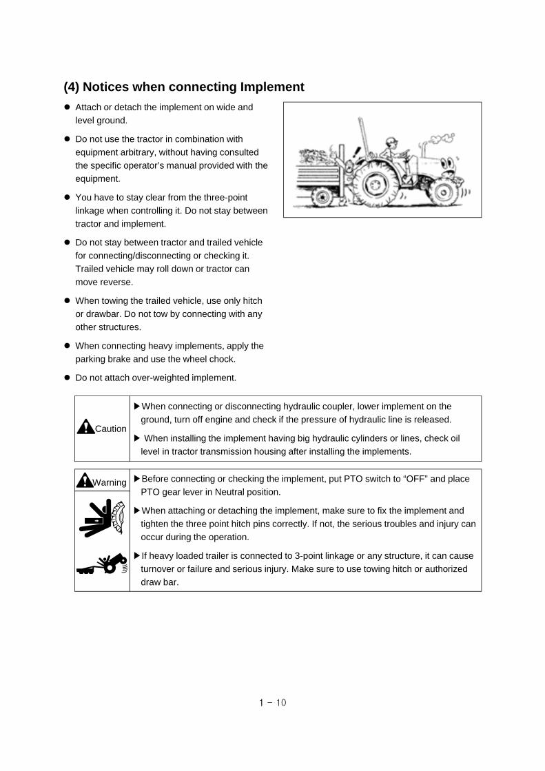
Attach or detach the implement on wide and
level ground.
Do not use the tractor in combination with
equipment arbitrary, without having consulted
the specific operator’s manual provided with the
equipment.
You have to stay clear from the three-point
linkage when controlling it. Do not stay between
tractor and implement.
Do not stay between tractor and trailed vehicle
for connecting/disconnecting or checking it.
Trailed vehicle may roll down or tractor can
move reverse.
When towing the trailed vehicle, use only hitch
or drawbar. Do not tow by connecting with any
other structures.
When connecting heavy implements, apply the
parking brake and use the wheel chock.
Do not attach over-weighted implement.
▶Before connecting or checking the implement, put PTO switch to “OFF” and place
PTO gear lever in Neutral position.
▶When attaching or detaching the implement, make sure to fix the implement and
tighten the three point hitch pins correctly. If not, the serious troubles and injury can
occur during the operation.
▶If heavy loaded trailer is connected to 3-point linkage or any structure, it can cause
turnover or failure and serious injury. Make sure to use towing hitch or authorized
draw bar.
Warning
(4) Notices when connecting Implement
▶When connecting or disconnecting hydraulic coupler, lower implement on the
ground, turn off engine and check if the pressure of hydraulic line is released.
▶ When installing the implement having big hydraulic cylinders or lines, check oil
level in tractor transmission housing after installing the implements.
Caution

1 - 11
Check the horizontal and vertical permissible load of the hitch (or drawbar) before towing. The load
is different with trailer brake, and stopping distance increases with speed and weight of towed loads
and slope. Make sure you consider the total weight of the equipment and its load. (See section 4. “Hitch and Drawbar” in this manual.)
Drive slowly when towing extremely heavy loads.
Do not tow trailers that are not fitted with an independent braking system.
(5) Notices when towing the tractor
If your tractor needs to be towed for a short
distance, Use the hitch (or drawbar) or front
towing hook. Do not connect to other structures
such as rear axle, ROPS, front axle, steering
components for towing.
Tractor can be steered for a short distance
without engine running, but it will be hard to turn
the steering wheel. If possible, run the engine for
steering and lubrication.
When being towed, disengage the 4WD,
differential lock, parking brake and place all gear
shift levers in neutral position.
(6) Notices when transporting the tractor
When transporting the tractor by truck, trailer,
etc, use suitable equipment or facilities to
load or unload the tractor.
Fix the tractor tightly to the vehicle with heavy-
duty straps or chains.
When fixing the rear of the tractor, use the hitch
or hitch support.
When fixing the front of the tractor, use the
towing hook.
When driving on public roads, the transporting
vehicle must have signs and lights required by
local regulation to avoid collision with a vehicle.
▶ When fixing the tractor, Do not hook or connect chains to the 4WD shaft, steering
cylinder, tie-rod or front axle. These can be damaged by the chain or excessive
strain.
▶ In case of turbocharger engine (where fitted), cover the exhaust outlet to protect
that the turbocharger does not rotate by air without lubrication.
Caution

1 - 12
(7) Notices when servicing the tractor after work
The check and maintenance must be performed after stopping the engine and cooling down the
engine sufficiently.
Warning▶When opening the radiator cap,
hot cooling water or steam may
explode. Remove the cap using
a thick rag or glove to prevent
serious burns.
Keep an approved fire extinguisher on your tractor.
Never fill the fuel tank while the engine is running or the engine is hot. And never smoke or have
flames around fuel tank.
To prevent fire or explosion, keep flames or sparks away from battery. Do not grind or smoke or
weld near a battery. For further information, see section 5. “Battery handling and Notices”.
▶Always remove grounded (-) battery clamp first and assemble it last. If not, It can
cause an explosion by spark.
▶The gas generated from the battery is explosive. Keep cigarettes, sparks and
flames away from battery. Never check battery charge by placing a metal object
across the terminals.
▶Sulfuric acid in battery electrolyte is poisonous. It is strong enough to burn skin,
clothing and can cause blindness if splashed into eyes. Do not touch the battery or
liquid by bare hand without gloves or any protection. Flush eyes with clean water for
about 20 minutes If the electrolyte is splashed into the eyes. Get medical attention
immediately.
▶Do not short circuit the battery posts with metal items.
▶Battery post, terminals and related accessories contain lead and lead compounds.
MUST WASH YOUR HANDS AFTER HANDLING.
Warning
DO NOT pour water into the radiator or engine
when the engine is hot. The engine or radiator
may crack.
Warning ▶Before removing hydraulic pipes or hoses and other parts, make sure to check that
hydraulic pressure is relieved completely. The leaks of pressurized oil can cause a
fatal physical injury.
▶Use proper protection equipments, before servicing hydraulic system.
▶Before connecting or disconnecting the hydraulic quick coupler, lower the
implements to the ground, and check that hydraulic pressure is relieved.
Before checking or repairing the hydraulic system and fuel system, make sure the engine is stopped,
and all the transmission gears are in neutral, and lower the implements to the ground. The leaks of
pressurized fluid can cause a fatal physical injury. If injured by leaking fluid, get medical attention
immediately

1 - 13
(8) Notices when handling Diesel Fuel
Do not mix gasoline, alcohol or blended fuels to diesel fuel. These mixtures are explosive in fuel
tank.
Never remove the fuel cap or refuel with the engine running or hot.
Do not smoke while refueling the tractor. Keep any type of flame away.
Maintain control of the fuel filler nozzle when filling the fuel tank.
Do not fill the fuel tank to capacity. Fill only to the bottom of the filler neck to allow room for
expansion.
Wipe up spilled fuel immediately and always tighten the fuel tank cap securely.
If the original fuel tank cap is lost, replace it with an approved one.
Never use fuel for cleaning purposes.
Arrange fuel purchases so that summer grade fuels are not held over and used in the winter.
Before operating with Bio-Diesel, contact your authorized dealer for information relating to the use
and storage of Bio-Diesel.
Before servicing the tractor, attach a “DO NOT
OPERATE” warning tag to the tractor in an area
that will be visible.
See other side
Reason :
DO NOT
OPERATE
DO NOT
OPERATE
Signed by :
Tel :
It is advisable to keep a First-aid kit on your tractor.
Keep the area used for servicing the tractor clean and dry. Wet or oily floors are slippery. It can be
dangerous when working with electrical equipment.
Remove all litter or debris from the tractor. Especially check the engine area and exhaust system.
Do not attempt to remove or unfasten the air conditioning components arbitrary. There is a possible
to be severely frostbitten or injured by escaping refrigerant. Contact your authorized dealer to work
air conditioning systems.

1 - 14
Stop the tractor on level ground.
Place the transmission gear in neutral and put
PTO switch to “OFF” position.
Lower the mounted implements on the ground.
Apply the parking brake.
Stop the engine and remove the ignition key.
Before you leave the operator’s station, wait for
engine and all moving parts to stop.
Have to apply the wheel chock when parking the
tractor on a slope unavoidably.
▶ When parking the tractor on a slope unavoidably while attaching the loaded
equipment, the tractor may move even if the parking brake is applied. Apply the
wheel chock and low speed transmission gear as follow.
-. Mechanical : downhill ⇒ Reverse 1gear / uphill ⇒ Forward 1gear
-. HST type : Lowest gear
Caution
(9) Notices when leaving the tractor
(10) Notices relating to Toxic substances
Exhaust gas and some its constituents of the Diesel engine are known to the State of California to
cause cancer, birth defects, and other reproductive harm. (California proposition 65)
Battery post, terminals and related accessories contain lead and lead compounds. MUST WASH
YOUR HANDS AFTER HANDLING.

1 - 15
XR45 / XR45HST XR50 / XR50HST XR60
Driver-perceived sound level
Noise level 85.8 / 87.2dB(A) 87.8 / 89.2dB(A) 87.9dB(A)
Test method Annex Ⅱ / Ⅰ Annex Ⅰ Annex Ⅰ
Directives 2009/76/EC
Pass-by N
oise
Noise level 79.1 / 80.1dB(A) 80.2 / 81.2dB(A) 80.2dB(A)
Directives 2009/63/EC-Annex Ⅵ
(11) Noise Levels
This tractor has an equivalent continuous A–weighted sound pressure level at the operator ear as
below.
(12) Vibration Levels
The Whole Body Vibration (WBV) level will depend on a lot of parameters. The properties of the
track or field surface and the driving speed will be the main parameters.
The vibrations of the tractor cause discomfort to the driver and in some cases his health and safety
may be at risk.
Adjust the driver’s seat to suit operator’s size and weight.
Do not start or stop the tractor quickly. Operate the tractor smoothly.
In compliance with EU standards, 78/764/EEC, the vibration level measured on seat for tractors
described in this manual are as below.
Seat Model / Type Vibration m/s² (ft/s²) Testing mass
WOOCHANG (W08SSS or W09SSS or
W10SSS)
1.24 (4.07) 59kg
1.12 (3.67) 98kg
Input Vibration : Category A Class Ⅰ,Ⅱ, Ⅲ
1 - 16
1-3. Long-term storage
(1) Preparation for storage
※ Wash the tractor cleanly and follow the procedure
as below.
Apply grease or lubricant oil or spray paint to the
non-painted metal to avoid corrosion. Keep the
tractor in a covered, dry and well-ventilated place.
Temperature : 10 ~ 35 (50 ~ 95 )
Humidity : 45% ~ 70%
Place all controls, including electrical switches, in
neutral position and apply the wheel chock to the
tires and disengage the parking brake.
Check the lubricant capacity of each part and if the
engine oil has exceeded 100 hours of work,
change the oil and run the engine for 5 minutes at
idle rpm.
Drain the engine coolant completely. If the engine
coolant is anti-freeze solution, it is not necessary
to drain but check its concentration.
Fill the fuel tank full with fuel.
Loosen all drive belts and clean the air cleaner.
Loosen the rubber plug (if fitted) under the clutch
chamber to drain water.
Remove the battery, clean the cover and smear the
terminals with grease. Place the battery in a
ventilated place not less than 10°C (50°F) and
away from direct sunlight.
Warning▶ When restarting the engine at the end of long-term storage, follow the instructions
of “Preparation for Reuse”. (See next page)
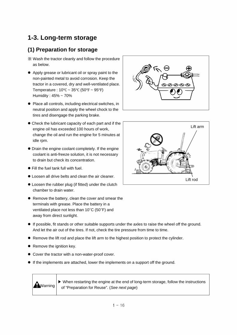
Lift rod
Lift arm
If possible, fit stands or other suitable supports under the axles to raise the wheel off the ground.
And let the air out of the tires. If not, check the tire pressure from time to time.
Remove the lift rod and place the lift arm to the highest position to protect the cylinder.
Remove the ignition key.
Cover the tractor with a non-water-proof cover.
If the implements are attached, lower the implements on a support off the ground.
1 - 17
(2) Check & Maintenance during storage
Apply grease or lubricant oil to non-painted metal to avoid corrosion.
Check the leakage of fuel, oil and coolant. If necessary, repair the damaged part.
Check the tire air pressure and maintain the proper pressure.
The battery should be charged about once a month not to be discharged entirely.
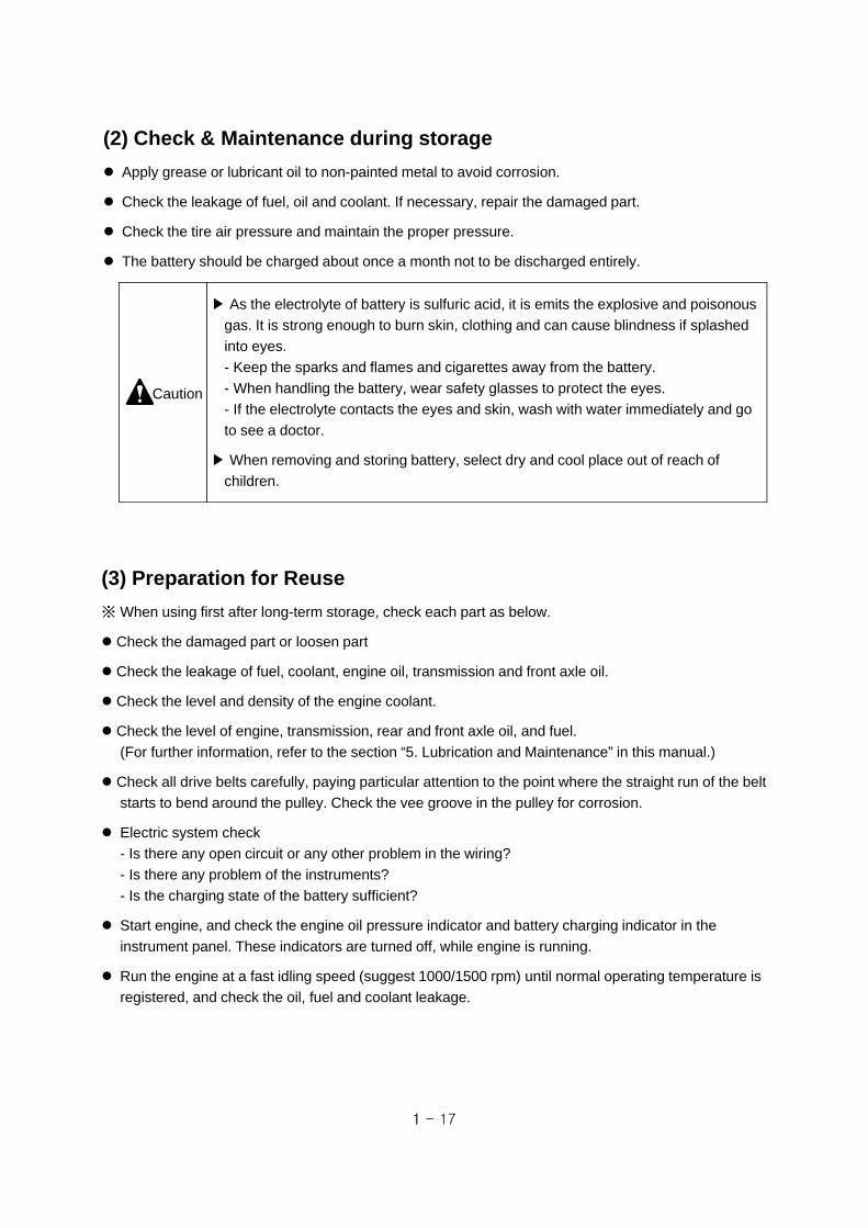
▶ As the electrolyte of battery is sulfuric acid, it is emits the explosive and poisonous
gas. It is strong enough to burn skin, clothing and can cause blindness if splashed
into eyes.
- Keep the sparks and flames and cigarettes away from the battery.
- When handling the battery, wear safety glasses to protect the eyes.
- If the electrolyte contacts the eyes and skin, wash with water immediately and go
to see a doctor.
▶ When removing and storing battery, select dry and cool place out of reach of
children.
Caution
(3) Preparation for Reuse
※ When using first after long-term storage, check each part as below.
Check the damaged part or loosen part
Check the leakage of fuel, coolant, engine oil, transmission and front axle oil.
Check the level and density of the engine coolant.
Check the level of engine, transmission, rear and front axle oil, and fuel.
(For further information, refer to the section “5. Lubrication and Maintenance” in this manual.)
Check all drive belts carefully, paying particular attention to the point where the straight run of the belt
starts to bend around the pulley. Check the vee groove in the pulley for corrosion.
Electric system check
- Is there any open circuit or any other problem in the wiring?
- Is there any problem of the instruments?
- Is the charging state of the battery sufficient?
Start engine, and check the engine oil pressure indicator and battery charging indicator in the
instrument panel. These indicators are turned off, while engine is running.
Run the engine at a fast idling speed (suggest 1000/1500 rpm) until normal operating temperature is
registered, and check the oil, fuel and coolant leakage.

1 - 18
Soil, Air and Water are essential elements for human life. To contribute to environment
preservation of the Earth, we are trying to minimize the environment pollution necessitated by
general business activity such as product design, manufacturing, distribution, etc.
Several substances and products derived from chemical and petrochemical products are major
portion of environment pollution and must be disposed of according to environment laws or
related regulations, and common sense.
We’d like to notify the following items for “Use & Disposal” related to environment preservation.
1. Avoid the overload work after reading the Operator's Manual.
Overload work may reduce the life of the product as well as the unburned exhaust gas
occurred during overload work becomes the major cause of air pollution.
2. When you replace various oils (engine, transmission, anti-freeze solution) directly, do not
throw the exhausted waste oil to any place.
This may pollute the soil and water seriously and also is prohibited legally. If violating, you
would be responsible for that by civil or criminal case. The waste oil must be disposed
according to the environment laws.
3. Use the product according to the Operator's Manual and if the life of product ended, do not
throw away (or dispose) to any place. The rust water or oil coming from the disposed
product may cause the pollution of soil or water. Thus, the wasted product must be
disposed lawfully, contact your authorized dealer nearby.
4. Modern lubricants contain additives. Do not burn the disposed oil or fuel in conventional
heating systems.
5. When you drain or fill the fuel, lubricants oil and coolants, do not left to be absorbed into the
ground. They must be collected and disposed in a suitable manner.
6. Do not adjust the setting of the fuel delivery system. This will alter the emission of exhaust
fumes.
1-4. Notices for ”Use & Disposal” related to the environment

1 - 19
Gear Neutral
The followings show the symbols and its meaning used for the tractor.
1-5. Symbols
Low speed
High speed
Engine speed control (throttle)
Engine speed control (throttle)
Position control(Up)
Position control(Down)
Draft control(Deep)
Draft control(Shallow)
Forward/Rearward
Forward
Backward
4WD disconnection
4WD connection
Quick turn(optional)
Parking brake
Turn signal light
Headlights (downward)
Side lights
Headlights(upward)
Work light
Light switch
Emergency lights
Cylinder rod (shorten)
Cylinder rod (extend)
Cylinder rod (floating)
Window wiper
Window wiper/ Washer (front)
Window wiper/ Washer (rear)
Cruise drive(optional)
Cruise driverelease (optional)
Fuel level
Refer to operator’sManual.
Fuel filter
Battery charging
Caution!
Transmissionoil pressure
Engine oil press-ure
Engine coolanttemperature
Diesel engine preheat
Differential lockdevice
horn
Engine stop
PTO in operation
PTO stop
Engine start
One side brakelight (optional)
DPF temperatureDPF regeneration DPF inhibited
Engine warning

1 - 20
(2) Safety Decals and Attaching position
1-6. Safety Decals
(1) Handling and Maintenance of Safety Decals
For intended use and personal safety of the operator, the safety decals (labels) are attached to the
parts related with safety operation.
Before operating or maintenance of the tractor, check the position and read the instructions carefully.
▶ The instructions described on the safety decals are very important for the safety of
the operator and workers around. If ignored, it may cause the death or serious
injury.
▶ If the decals are dirty, wash them with soap water and wipe with soft rags. Do not
use the thinner, acetone, or other harsh chemicals as it may erase the instructions.
▶ If the decal is detached or damaged, replace it with a new one on original position.
▶ When cleaning the tractor with pressurized water, the decals can be detached.
▶ If a decal is on a part that is replaced, make sure the decal is attached on the new
part.
Caution
If you find “Read Operator’s Manual” symbol (1) in
the decals, refer to the appropriate page of the
operator’s manual for further information regarding
operation, adjustment and maintenance.
1
7
8
2
5
4
9
11
3
1
1 - 21
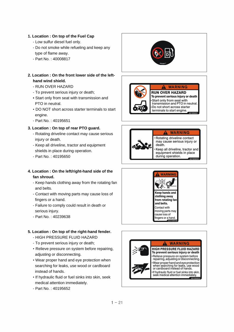
1. Location : On top of the Fuel Cap
- Low sulfur diesel fuel only.
- Do not smoke while refueling and keep any
type of flame away.
- Part No. : 40008817
2. Location : On the front lower side of the left-
hand wind shield.
- RUN OVER HAZARD
- To prevent serious injury or death;
• Start only from seat with transmission and
PTO in neutral.
• DO NOT short across starter terminals to start
engine.
- Part No. : 40195651
3. Location : On top of rear PTO guard.
- Rotating driveline contact may cause serious
injury or death.
- Keep all driveline, tractor and equipment
shields in place during operation.
- Part No. : 40195650
4. Location : On the left/right-hand side of the
fan shroud.
- Keep hands clothing away from the rotating fan
and belts.
- Contact with moving parts may cause loss of
fingers or a hand.
- Failure to comply could result in death or
serious injury.
- Part No. : 40239638
5. Location : On top of the right-hand fender.
- HIGH PRESSURE FLUID HAZARD
- To prevent serious injury or death;
• Relieve pressure on system before repairing,
adjusting or disconnecting.
• Wear proper hand and eye protection when
searching for leaks, use wood or cardboard
instead of hands.
• If hydraulic fluid or fuel sinks into skin, seek
medical attention immediately.
- Part No. : 40195652
1 - 22
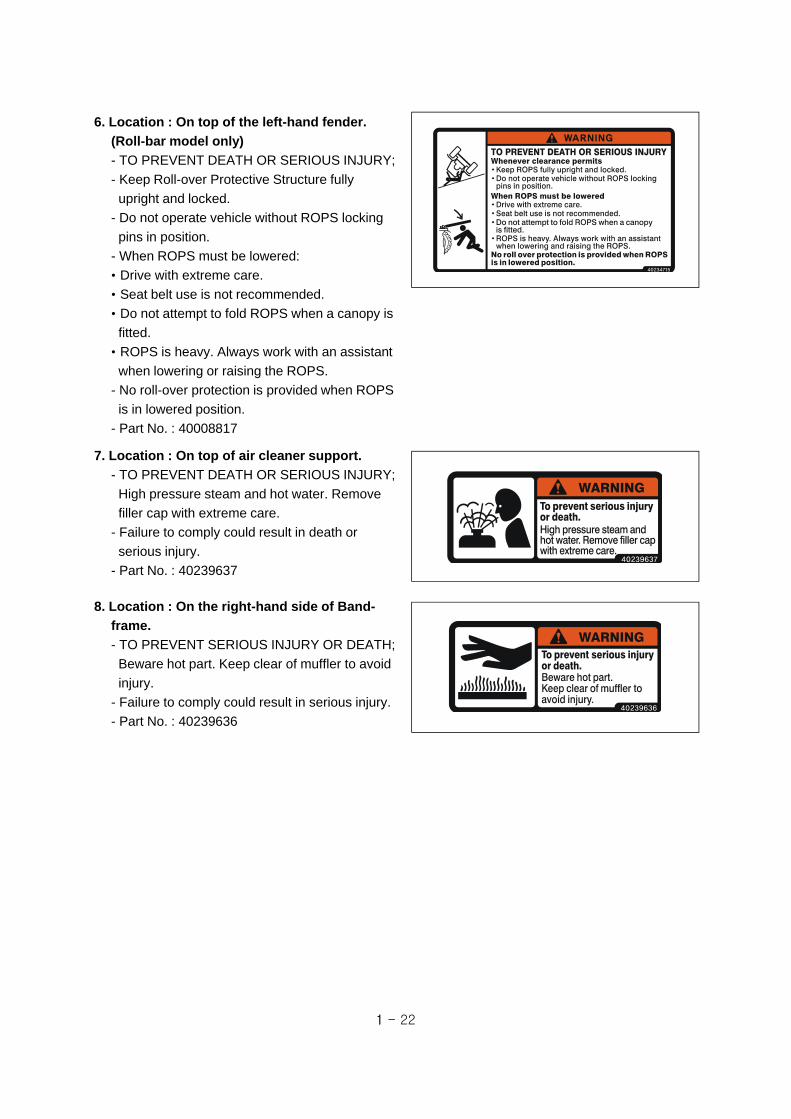
6. Location : On top of the left-hand fender.
(Roll-bar model only)
- TO PREVENT DEATH OR SERIOUS INJURY;
- Keep Roll-over Protective Structure fully
upright and locked.
- Do not operate vehicle without ROPS locking
pins in position.
- When ROPS must be lowered:
• Drive with extreme care.
• Seat belt use is not recommended.
• Do not attempt to fold ROPS when a canopy is
fitted.
• ROPS is heavy. Always work with an assistant
when lowering or raising the ROPS.
- No roll-over protection is provided when ROPS
is in lowered position.
- Part No. : 40008817
7. Location : On top of air cleaner support.
- TO PREVENT DEATH OR SERIOUS INJURY;
High pressure steam and hot water. Remove
filler cap with extreme care.
- Failure to comply could result in death or
serious injury.
- Part No. : 40239637
8. Location : On the right-hand side of Band-
frame.
- TO PREVENT SERIOUS INJURY OR DEATH;
Beware hot part. Keep clear of muffler to avoid
injury.
- Failure to comply could result in serious injury.
- Part No. : 40239636

1 - 23
9. Location : On the left-hand pillar for Cabin
model / On top of left-hand fender for Roll-
bar model.
① CAUTION
- PTO selector & lever must be in “OFF” position
to start engine.
- Do not operate on hard surfaces with 4WD
engaged.
② WARNING
- TO PREVENT SERIOUS INJURY OR DEATH;
• After first hour of operation and daily thereafter,
check front and rear wheel lug nuts and bolts
for proper torque.
• PTO - keep hands, feet and clothing away from
PTO & other moving parts.
• Disengage PTO and shut off engine before
servicing tractor or implements, or attaching /
detaching implements.
• Keep all safety shields in place for your
protection.
• Pull only from approved drawbar or lower links
of 3-point hitch at horizontal position or below.
• Lock tractor brake pedals together for travel on
roads or highways.
• Always apply parking brake and shift
transmission to neutral before dismounting.
• Always use a seat belt when you operate the
tractor.
• Allow no riders on tractor or implements.
• Do not use a seat belt when operating with
folding ROPS in lowered position.
• Engine exhaust fumes can cause death or
sickness. Always try to work in a ventilated
area.
• Disengage the differential lock when turning
the tractor. Always disengage the differential
lock when driving on roads.
• Depress on or both brake pedals to disengage
the differential lock.
- Failure to comply could result in death or
serious injury.
- Part No. : 40195656

1 - 24
10. Location : On the left-hand side of the
ROPS frame. (Roll-bar model only)
- TO PREVENT SERIOUS INJURY OR DEATH;
• Never operate a tractor without a certified
ROPS.
• Always fasten seat belt when operating tractor
with ROPS in upright position.
• Do not operate the tractor on steep slopes or
drop-off.
• Avoid sharp turns at high speeds.
• Use of ROPS and seat belt reduce the chance
of injury or death in roll-over or upset occur.
• Do not attach ropes or chains to ROPS for
pulling purpose.
- Failure to comply could result in death or
serious injury.
- Part No. : 40234561
11. Location : On the right-hand pillar for Cabin
model / On the right-hand fender for Roll-bar
model. (optional)
- JOYSTICK LEVER USAGE.
- TO AVOID PERSONAL INJURY; Wrong
operation causes serious injury easily.
Push the lever(1) in to lock the joystick in
neutral.
- Failure to comply could result in death or
serious injury.
- Part number : 40194109

2 - 1
2. Instruction for safe operation
(1) The name of each part
① Cabin type
Instrument panel
Steering wheel
Driver’s Seat
Sub step
Head lights
Cabin
Bonnet (Hood)
Front ballast weight(optional)
Front axle
Fender
Fuel tank

2 - 2
▶ Operator’s condition : The persons such as patients, drunks, people on drugs,
etc. are never allowed to operate this tractor.
Only well educated operators can use the tractor after learning the usage of
controls for moving, stopping, turning and other operating.
▶ Do not grasp the gear levers when entering the cabin from the right-hand side.
2-1. Boarding and Exiting the tractor
Push button
Door grip
Sub step
Grab handle
Caution
(1) Boarding the tractor
① Cabin type
Whenever possible, use the left-hand side door for entering.
Release the cabin door locked with the provided key and open the cabin door after pressing the push-button.
When boarding the tractor, use the sub-step and grab handles provided on the cabin frame and door.
Do not jump up/down for your safety.
When leaving the tractor, lock the cabin door and remove the key.

2 - 3
(3) Tilting steering wheel
Push the tilt lever downward to release the
steering wheel and tilt the steering wheel to
desired position.
Release the tilt lever to lock the steering wheel in
place, and check to make sure the column does
not moved forward and backward.
Adjust the steering wheel only when the tractor
has stopped.
▶DO NOT adjust steering wheel while driving. It may cause a serious accident.Caution
Lock
ReleaseTilt lever
warning▶Do not arbitrarily remove the seat switch. If it is necessary to replace the seat, the
seat switch has to be replaced together. If not, the engine is not started.
(2) Driver’s seat (HST type)
At the lower end of the seat, there is a switch to detect that operator is sitting in seat.
If the operator gets up from the seat while engine is running, the engine will stop automatically for safety in case of ;
- getting up from the seat for more than 2 seconds with HST pedal NOT in neutral position.
- the HST pedal is in NEUTRAL and rear PTO is engaged without applying the parking brake.
- the Middle PTO lever (optional) is engaged.
Seat switch
Before leaving the driver’s seat, turn the PTO switch to OFF and place the Middle PTO lever (optional) on OFF position, and apply the parking brake.

2 - 4
Seat belt(5) Seat belt
Always wear the seat belt before operating the
tractor and adjust the belt to fit the operator.
1. Insert the seat belt end into the buckle until a
“click” indicates it is properly engaged.
2. To remove the seat belt from the buckle,
press the red release button on the buckle.
Check the seat belt regularly. If damaged or
frayed, replace it with a new one.
Warning ▶If not wearing the seat belt, it may cause serious injury in case of accident.
- During operation, it must be required to wear seat belt with a cab or safety frame
installed.
- After wearing the seat belt, adjust the belt to fit the operator.
▶If safety frame is folded down for frame model, do not wear the seat belt.
Buckle
warning
▶DO NOT put your hand under the seat while sitting. It may cause a injury by seat suspension.
▶DO NOT adjust the seat position while driving.
(4) Seat adjustment
Before operating the tractor, adjust the position of driver’s seat according to body size and length.
Seat F/R adjustment lever
1) After sitting on driver’s seat, move the seat F/R adjustment lever up to release the lock.
2) Move the driver’s seat forward or backward depending on driver’s body length.
3) Release the seat F/R adjustment lever and check the seat is locked.
Seat height adjustment knob
1) If you turn the seat height adjustment knob clockwise, the seat height shall be lowered.
Weight adjustment knob
1) Adjust the seat suspension depending on your body weight by using the weight adjustment knob. If you turn the knob clockwise, the suspension stiffness shall be increased.
Seat height
adjustment knob
Seat F/R
adjustment lever
Weight
adjustment knob
2 - 5
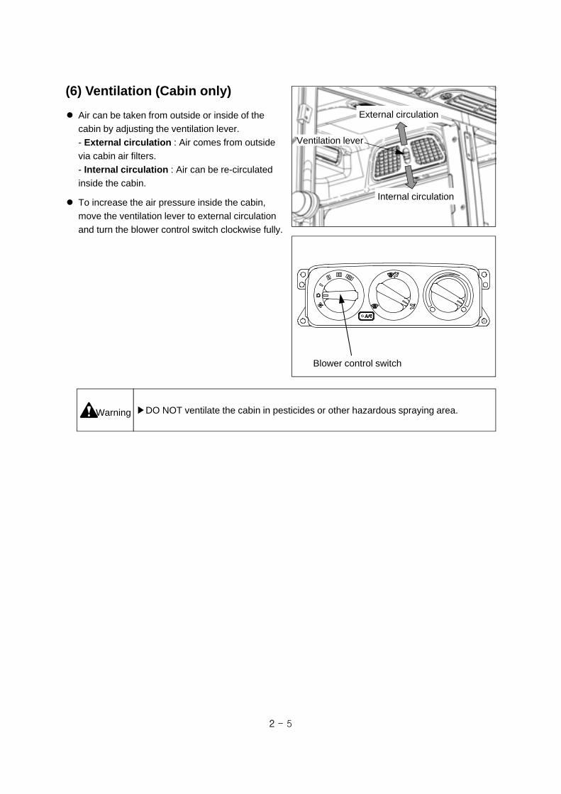
(6) Ventilation (Cabin only)
Air can be taken from outside or inside of the
cabin by adjusting the ventilation lever.
- External circulation : Air comes from outside
via cabin air filters.
- Internal circulation : Air can be re-circulated
inside the cabin.
To increase the air pressure inside the cabin,
move the ventilation lever to external circulation
and turn the blower control switch clockwise fully.
Blower control switch
Warning ▶DO NOT ventilate the cabin in pesticides or other hazardous spraying area.
Ventilation lever
External circulation
Internal circulation
2 - 6
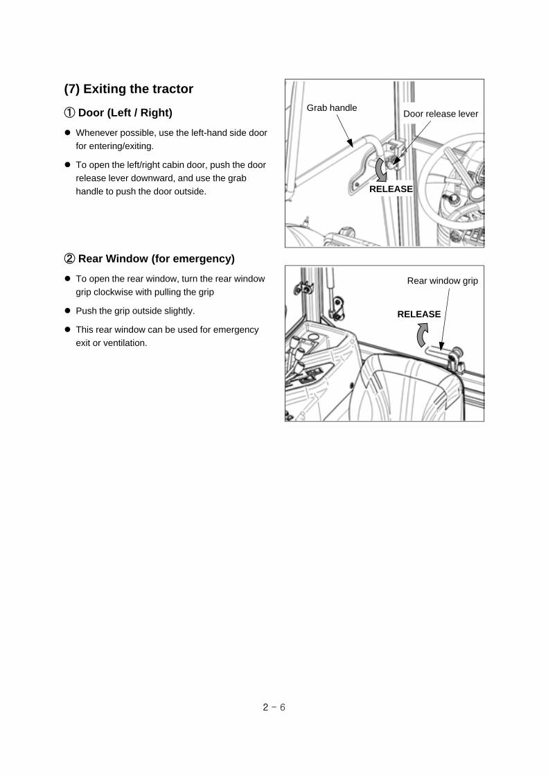
Grab handle
(7) Exiting the tractor
① Door (Left / Right)
Whenever possible, use the left-hand side door
for entering/exiting.
To open the left/right cabin door, push the door
release lever downward, and use the grab
handle to push the door outside.
Door release lever
RELEASE
Rear window grip
RELEASE
② Rear Window (for emergency)
To open the rear window, turn the rear window
grip clockwise with pulling the grip
Push the grip outside slightly.
This rear window can be used for emergency
exit or ventilation.

2 - 7
2-2. Safety device
(2) Fender
Fender is a protection device to prevent an
unintended access to the rear tires and to
prevent mud from irrupting to the driver.
Do not remove and modify the fender.
(1) Hood (Bonnet)
Hood is a protection device to prevent an
unintended access to the rotating parts around
engine ; cooling fan, fan belt and rotating shaft
and pulley.
Do not remove and modify the hood.
PTO shaft protection cap
PTO safety cover
Warning ▶If you contact the rotating shaft, it may cause a severe injury.
- DO NOT try to touch the rotating shafts.
- DO NOT remove the protection covers.
- Avoid loose clothes that can easily be rolled up in the rotating shaft.
(3) PTO safety cover and protection cap
PTO safety cover is a protection device to prevent
an unintended access to the PTO shaft and to
prevent an accident causing by the rotating drive
shaft.
Do not remove the PTO safety cover. If the PTO
safety cover or protection cap is damaged or
removed, replace it with a genuine part.
Do not step on the PTO safety cover.
After using the PTO shaft, apply grease and insert
the PTO shaft protection cap.
Fender
Hood (Bonnet)

2 - 8
(4) Roll Over Protective Structure (ROPS)
① Cabin
The Protective Structure (Roll-bar or Cabin) and interconnecting components are a certified system.
Any damage, Fire, corrosion or modification will weaken the structure and reduce your protection. If
this occurs, the Protective Structure MUST be replaced with a new one. Contact your authorized
dealer for Protective Structure inspection and replacement.
Warning
▶As the cabin is very important structure for driver’s safety, DO NOT modify (welding,
drilling, cutting, etc) or remove it arbitrarily.
▶Do not step on the fender for the maintenance of cabin roof.
Cabinframe
3 - 1
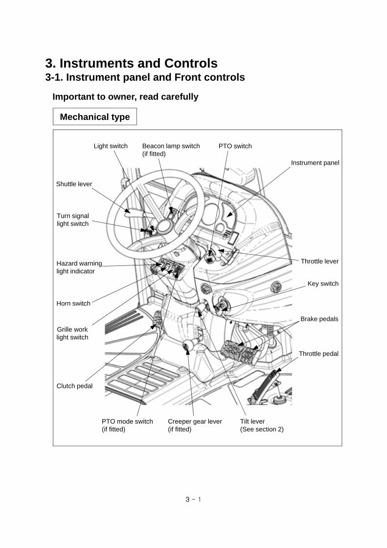
3. Instruments and Controls3-1. Instrument panel and Front controls
Clutch pedal
Light switch
Turn signallight switch
Hazard warninglight indicator
Horn switch
Grille worklight switch
Shuttle lever
Key switch
Brake pedals
Throttle pedal
Instrument panel
Important to owner, read carefully
Throttle lever
PTO switchBeacon lamp switch(if fitted)
PTO mode switch(if fitted)
Creeper gear lever(if fitted)
Tilt lever(See section 2)
Mechanical type

3 - 2
Brake pedals
Light switch
Turn signallight switch
Hazard warninglight indicator
Horn switch
Grille worklight switch
Key switch
HST forwardpedal
HST reversepedal
Instrument panel
Throttle lever
PTO switchBeacon lamp switch(if fitted)
PTO mode switch(if fitted)
Tilt lever(See section 2)
HST type
Cruise control switch

3 - 3
(1) Instrument panel
12
6
2
7
8
910 11 12 13
15
16
14
17
3
4
5 18
21
19
20
22 Turn signal indicator
3 Cold start aid indicator
4 PTO operation indicator
5 4WD indicator (Not used)
6 Quick turn indicator (Not used)
7 Creeper speed indicator (Not used)
8 High beam indicator
9 Low / High speed indicator (Not used)
10 Engine coolant temperature gauge
11 Tachometer
12 Hour meter
13 Fuel level gauge
14 Fuel filter warning indicator
15 Hyd. oil pressure indicator (Not used)
16 Battery charging indicator
17 Engine oil pressure indicator
18 Parking brake indicator
19 One side brake indicator (Not used)
20 Cruise drive indicator (HST only)
21 Differential lock indicator (Not used)
1 Forward-reverse indicator (Not used)
This indicator is not used.
1 Forward-reverse indicator (Not used)
2 Turn signal indicator (Left / Right)
When the front/rear turn signal lights are blinked, This indicator shall be blinked simultaneously.

3 - 4
When turning the key switch to ON position, the
cold start aid device begins to work, and this
indicator shall be ON for about 10 seconds.
3 Cold start aid indicator
4 PTO operation indicator
5 4WD indicator (Not used)
6 Quick-Turn indicator (Not used)
7 Creeper speed indicator (Not used)
8 High beam indicator
When turning on high beam of the headlamp,
This indicator shall be ON simultaneously.
43
5
6
9 Low / High speed indicator (Not used)
7
8
9 10
This gauge indicates the temperature of engine coolant.
The closer the needle approaches H, the higher the temperature of engine coolant is.
The coolant is very hot. When checking the coolant, comply with instructions of the section 5
“Maintenance and Lubrication” in this manual.
10 Engine coolant temperature gauge
The tachometer shows the engine revolutions
per minute (“30” means 3000rpm).
The operating hour 0019.1 means the tractor
has been operated for 19.1hr (19 hr 6 min).
11 12
11 Tachometer
12 Hour meter
When key switch is ON, PTO switch is ON and
PTO mode switch(if fitted) is MANUAL, this
indicator shall be ON.
If the PTO mode switch is AUTO, this indicator
will be ON when clutch pedal is NOT depressed
and/or the 3-point linkage is NOT lifted up over
the upper limit.
(For further information, See page 3-9)
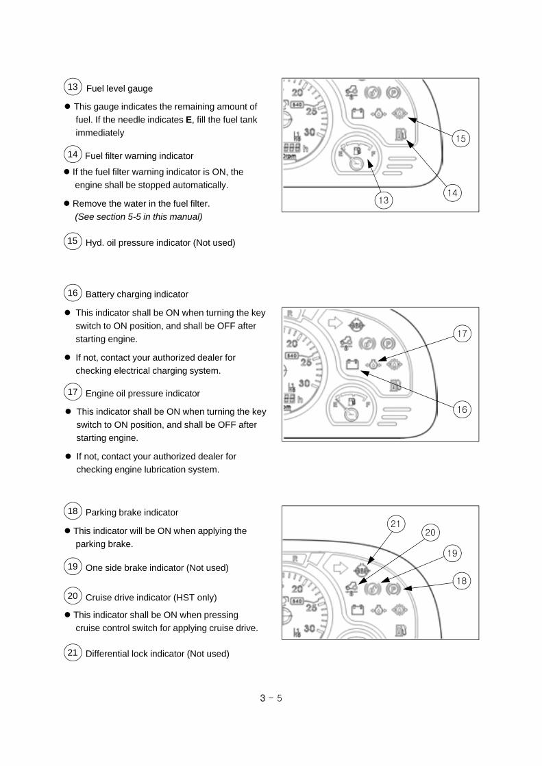
3 - 5
This gauge indicates the remaining amount of
fuel. If the needle indicates E, fill the fuel tank
immediately
If the fuel filter warning indicator is ON, the
engine shall be stopped automatically.
Remove the water in the fuel filter.
(See section 5-5 in this manual)
13 Fuel level gauge
14 Fuel filter warning indicator
15 Hyd. oil pressure indicator (Not used)
1314
15
This indicator shall be ON when turning the key
switch to ON position, and shall be OFF after
starting engine.
If not, contact your authorized dealer for
checking engine lubrication system.
This indicator shall be ON when turning the key
switch to ON position, and shall be OFF after
starting engine.
If not, contact your authorized dealer for
checking electrical charging system.
16
17
16 Battery charging indicator
17 Engine oil pressure indicator
18
2021
19
This indicator will be ON when applying the
parking brake.
18 Parking brake indicator
19 One side brake indicator (Not used)
20 Cruise drive indicator (HST only)
21 Differential lock indicator (Not used)
This indicator shall be ON when pressing
cruise control switch for applying cruise drive.

3 - 6
Turn signallight switch
(3) Turn signal light switch This switch is used to give information to other
vehicles when turning to the left or right.
If turning the switch to clockwise, the right turn
signal lights are blinking.
-If turning the switch to counter-clockwise, the
left turn signal lights are blinking.
▶ When changing direction
during running on the road,
operate the turn signal lights to
inform other vehicles of your
direction.
Left turn
Right turn
(4) Light switch
OFF - Instrument panel and lights OFF
- Instrument light and side lights ON
- Instrument light, side lights, head lights
(low beam) ON
- Instrument light, side lights, head lights
(high beam) ON
▶When passing with other vehicles in the opposite lane at night, turn the headlights
to low beam not to disturb on coming cars.
Light switch
Caution
Caution
(2) Key switch
OFF - power off (engine stop)
ON - power on & automatic glow
START - engine start
▶ Because the safety switch for start is engaged, start the tractor after pressing
clutch pedal.
▶ If the tractor is not in use, the ignition key should be removed.
Key switch
Caution
OFF
ON
Start

3 - 7
Hazard warninglight switch
(6) Hazard warning light switch
This is used to warn other vehicles in case of
emergency status. If you press the upper side of
the triangle switch, all turn signal lights
(front/rear, left/right) shall be blinking.
▶If you use the hazard warning lights for a long time, it may cause a increase of
electrical consumption. Do not use the hazard warning lights for a long time.Notice
Grille worklight switch
(7) Grille work light switch
This is used to turn on/off the work light of the
front grille.
ON - Press the upper side of the switch.
OFF - Press the lower side of the switch.
(5) Horn switch
Press the upper side of the switch for sounding
off the horn.
Horn switch

3 - 8
(8) Beacon lamp switch (if fitted)
It is used to turn on/off the beacon lamp
connected to the beacon connectors. The
beacon connectors are installed to the left/right-
hand side under cabin roof.
Press the upper side of the switch to turn on the
beacon lamp.
Beacon lamp switch
The cruise control switch is for HST type tractor.
Position A : Release the cruise drive.
Position B : Neutral.
Position C : Apply the cruise drive.
For cruise drive, press the upper side of the
cruise control switch in the state of pressing the
forward pedal. And then, the forward pedal shall
be fixed and the switch shall return to the
NEUTRAL.
To stop the cruise drive, press the both brake pedals or lower side of the cruise control switch. The
forward pedal returns to the neutral position and the cruise drive shall be disengaged.
▶DO NOT press the one-side brake during cruise driving. You have to connect the
left and right brake to avoid the possible accident before driving.
▶Do not operate the cruise control switch when pressing the reverse pedal.
Caution
Cruise control switch
(9) Cruise control switch (HST type)
Neutral

3 - 9
PTO switch
(10) PTO switch
The engine starts only when PTO switch is
placed in OFF position for safety.
After starting the engine, you must comply with
the operation procedure of the PTO switch as
follow.
1. Check the safety around the implement.
2. Turn the PTO switch to ON position to operate
the PTO.
3. Press the PTO mode switch to desired
position. Refer to the following instruction.
4. When the PTO is working, PTO operation
indicator on the instrument panel shall be ON.
5. If you want to stop the PTO temporarily while
operating, push the PTO switch to OFF position.
The PTO operation shall be OFF.
▶ Before attaching or checking the PTO driven equipment,
- Always place the PTO switch in OFF position, and PTO gear lever in NEUTRAL
position.
▶ If the PTO mode switch is placed in MANUAL position, PTO rotates even if the
implement moves up to upper limit. Pay attention to the surroundings to prevent a
accident.
▶ Do not engage the PTO at high engine speed. Sudden engagement can cause
damage to some implements and PTO clutch. Engage PTO at low RPM, and then
raise the engine speed up.
Warning
ON : PUSH AND TURNOFF : PUSH
PTO mode switch
(11) PTO mode switch (if fitted)
It is used to select AUTO or MANUAL mode of
PTO operation
When the PTO mode switch is placed on ;
- MANUAL : PTO shaft will rotate independent
on the clutch pedal or position control lever.
- AUTO : If pressing clutch pedal or lifting rear
implement over the specified position, the PTO
shaft shall be stopped.
PTO switch

3 - 10
(12) Shuttle lever (Mechanical)
This is used to select Forward or Reverse.
Forward : push the lever forward.
Reverse : pull the lever backward.
Before reversing the tractor, lower the engine
rpm and check the safety behind the tractor.
▶The operation of shuttle lever must be done after the tractor has stopped
completely. DO NOT operate the shuttle lever while tractor is moving. It may cause
a damage of synchronizer rings and gears.Caution
Forward
Reverse
Shuttle lever
(14) Throttle pedal (Mechanical)
This pedal is used to control engine speed when
running on the road.
When using the Throttle pedal, the throttle lever
must be placed on Low speed.
An electronic control sensor is attached on this
pedal. If there is an error relating with this sensor
while the engine is running, the engine speed
shall be fixed to 1500 rev/min, so called LIMP
HOME mode. Contact your authorized dealer.
Throttle pedal
(13) Throttle lever
This lever is used to control engine speed.
- Pull it backward for Low speed,
- Push it forward for High speed.
The throttle lever must be used only for work
field. When driving on the road, place the throttle
lever to low speed, and use the throttle pedal.
For HST model, An electronic control sensor is
attached on this lever. If there is an error relating
with this sensor while the engine is running, the
engine speed shall be fixed to 1500 rev/min, so
called LIMP HOME mode. Contact your
authorized dealer.
Throttle lever High speed
Low speed

3 - 11
▶ DO NOT ride your foot on the clutch pedal while driving.
▶ As the start safety switch is installed for the operator’s safety, if you don’t press the
pedal fully, it does not start.
Caution
(15) Clutch pedal (Mechanical)
This is used to engage or disengage the main
transmission clutch for starting engine and
shifting transmission gear.
Depress the clutch pedal quickly and fully and
release it slowly.
If the PTO mode switch is placed on MANUAL,
the PTO shaft will NOT stop, if the switch is
placed on AUTO, the PTO shaft will stop, when
pushing down on clutch pedal.
Clutch pedal
(16) Brake pedals
The brake pedals of your tractor can be operated
independently after disconnecting the brake
pedal lock pin. The left/right brake pedals
transmit braking force on each wheel.
When stopping the tractor, press both brake
pedals together.
To reduce the turning radius in the work field,
remove the brake pedal lock pin, and press only
the left/right pedal firmly.
DO NOT press the one side brake pedal while
the differential lock is engaged. It may cause
damage or failure of the axles.
Caution
▶When driving on the road,
engage the left/right brake
pedal by the lock pin.
- If pressing one side of brake
when running, the tractor may
turnover.
▶ While driving, do not ride brake
and clutch pedal.
Brake pedal lock pin
Brake pedals
Brake pedallock pin
Brake pedals
MEC
HST

3 - 12
Creeper gear lever
Creeper speed
Standard
▶As the revolution force of wheel axle is very high when working in creeper speed
range, the machine may not stop even if you press the brake pedals.
In this case, press the clutch pedal to cut off the power and operate the brake
pedals.
Caution
(18) Creeper lever (MEC, if fitted)
It is used to work with very low driving speed.
When doing general work or driving on road,
push the creeper lever downward for standard
speed.
Move the lever upward for creeper speed.
For driving speed, refer to the section 4, “Driving
speed”.
(17) HST forward/reverse pedal
(HST type)
Press the HST forward pedal slowly in order to
move forward and if release the pedal, it returns
back to the NEUTRAL position, and tractor stops.
The HST reverse pedal is as same as the HST
forward pedal operation.
warning
▶Press the brake pedal to prevent stopping distance from being extended when
driving in high speed .
▶DO NOT operate the pedal hastily. It may cause a shock to you.
HST reversepedal
HST forward
pedal

3 - 13
3-2. Right-hand controls and Cabin pillar
Work light switch (Cabin only)
Differential lock pedal
Important to owner, read carefully
Joystick lever(Section 3-4)
Window wiper switch (Cabin only)
Main gear shift lever
Electrical power outlet socket (Cabin only)
Indoor light (Cabin only)
Remote control lever (Section 3-4)
Back up switch(if fitted)
Position control lever(Section 3-4)
Turn up switch(if fitted)
Draft control lever(Section 3-4)
Mechanical type
(1) Main gear shift lever
(Mechanical) Four speed gear shift is available.
Main gear shift lever can be shifted with just depressing clutch pedal without stopping tractor.
Main gearshift lever
Notice
▶Operate main gear shift lever by correct H pattern. If operated diagonally, it may cause a failure.
42
31
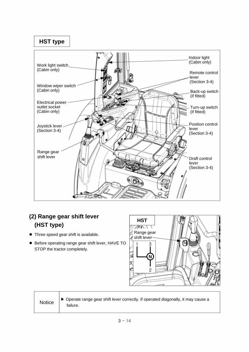
3 - 14
HST type
Work light switch (Cabin only)
Joystick lever(Section 3-4)
Window wiper switch (Cabin only)
Range gear shift lever
Electrical power outlet socket (Cabin only)
Indoor light (Cabin only)
Remote control lever (Section 3-4)
Back-up switch(if fitted)
Position control lever(Section 3-4)
Turn-up switch(if fitted)
Draft control lever(Section 3-4)
(2) Range gear shift lever
(HST type)
Three speed gear shift is available.
Before operating range gear shift lever, HAVE TO
STOP the tractor completely.
HST
Range gearshift lever
1
2
3
N
Notice▶ Operate range gear shift lever correctly. If operated diagonally, it may cause a
failure.
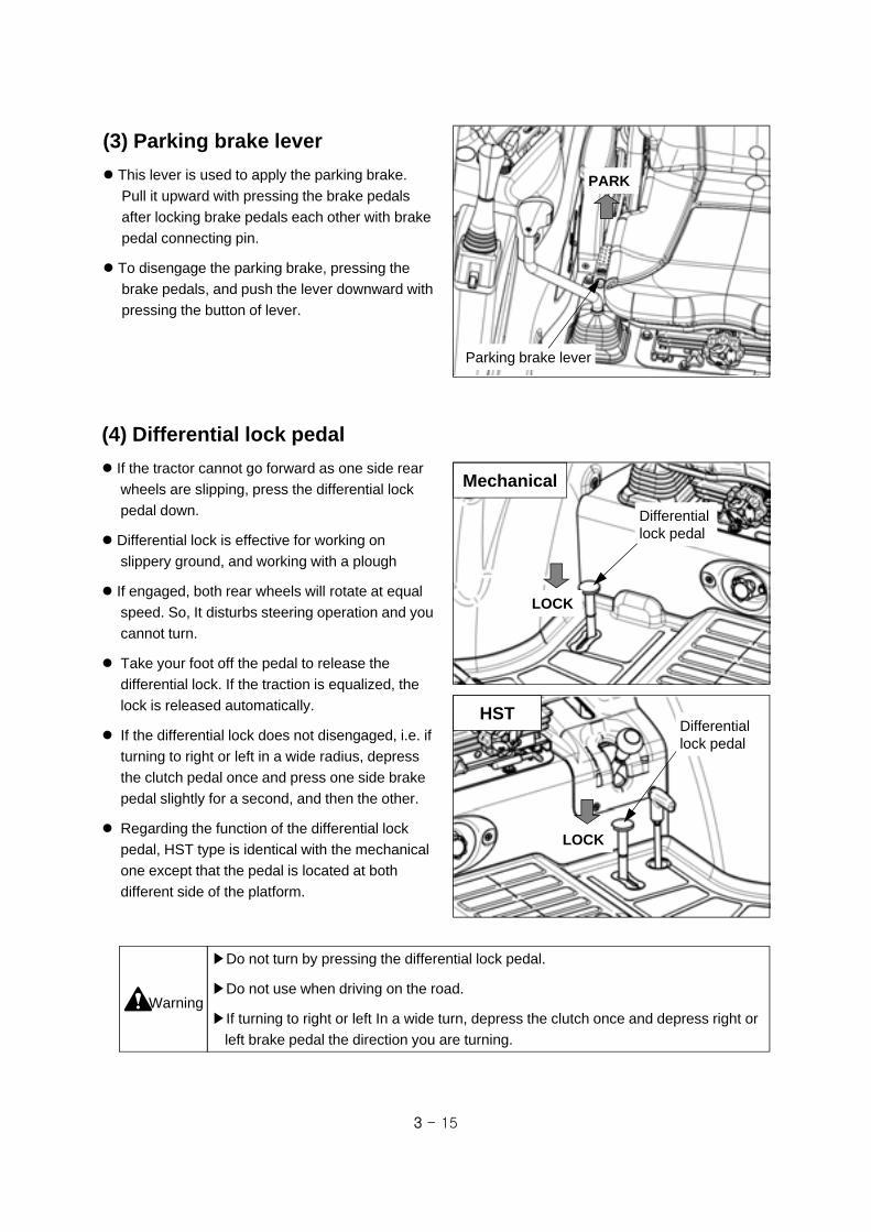
3 - 15
▶Do not turn by pressing the differential lock pedal.
▶Do not use when driving on the road.
▶If turning to right or left In a wide turn, depress the clutch once and depress right or
left brake pedal the direction you are turning.
Warning
Differential lock pedal
(3) Parking brake lever
This lever is used to apply the parking brake.
Pull it upward with pressing the brake pedals
after locking brake pedals each other with brake
pedal connecting pin.
To disengage the parking brake, pressing the
brake pedals, and push the lever downward with
pressing the button of lever.
Parking brake lever
PARK
(4) Differential lock pedal
If the tractor cannot go forward as one side rear
wheels are slipping, press the differential lock
pedal down.
Differential lock is effective for working on
slippery ground, and working with a plough
If engaged, both rear wheels will rotate at equal
speed. So, It disturbs steering operation and you
cannot turn.
Take your foot off the pedal to release the
differential lock. If the traction is equalized, the
lock is released automatically.
If the differential lock does not disengaged, i.e. if
turning to right or left in a wide radius, depress
the clutch pedal once and press one side brake
pedal slightly for a second, and then the other.
Regarding the function of the differential lock
pedal, HST type is identical with the mechanical
one except that the pedal is located at both
different side of the platform.
Mechanical
Differential lock pedal
HST
LOCK
LOCK

3 - 16
② Cabin type (Front, Rear)
This is used to turn on the front/rear work lights.
ON - Press the upper side (symbol part) of the
switch.
OFF - Press the lower side of the switch
(5) Work light switch
① Frame type (Rear)
Rear work light has a switch on its back. To turn
on/off the rear work light, operate the switch as
the right figure.
▶When driving on the road at
night, do not let the rear work
light stay “ON”. It may cause a
disturbance to the driver of the
following car.
Caution
Frontwork lightswitch
Rearwork lightSwitch(if fitted)
ON
OFF
This switch is used for operating front and rear
window wiper.
Press the upper side of its switch for operating
only the front/rear wiper.
If you press and hold the upper side of the
switch again, the washer liquid shall be sprayed
out.
▶Use wind shield washer liquid for automobile in winter time.
▶Do not operate the wiper without wind shield washer liquid, it may cause damage to
the wiper motor.
Caution
(6) Window wiper switch (Front, Rear)
Front windowwiper switch
Rear windowwiper switch(if fitted)

3 - 17
This is used to withdraw the electric power for
charging of the cigarette lighter jack or cellular
phone.
In case of using cigarette lighter jack (optional)
-If you push the cigarette lighter jack, the heating
coil generates heat and shall be used as
alternative of lighter.
In case of using as power supply (12V)
-Use the cellular phone charger less 10A.
Caution▶ When using a cigarette lighter jack, cares must be taken not to touch the heating
coil. The heat generated coil is very hot and may cause the danger of a burn.
(7) Electrical power outlet socket (Cabin only)
Power out socket
(8) Indoor light (Cabin only)
Press the lower side of indoor light to turn on the
light.
Press the lower side of indoor light again to turn
off the light. Indoorlight
(9) Audio player (Cabin only) (if fitted) Refer to the attached user’s manual for Audio player.
▶For safer operation, turn down the player volume so that you can hear sound from
outside of the tractor.
▶Do not use the headset while driving tractor.
Caution
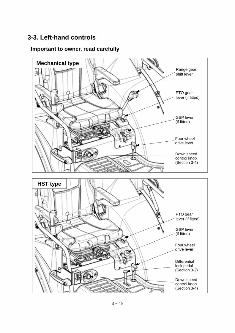
3 - 18
3-3. Left-hand controls
Four wheel drive lever
Range gearshift lever
PTO gearlever (if fitted)
Important to owner, read carefully
GSP lever(if fitted)
Down speed control knob (Section 3-4)
Mechanical type
HST type
Four wheel drive lever
PTO gearlever (if fitted)
GSP lever(if fitted)
Down speed control knob (Section 3-4)
Differentiallock pedal(Section 3-2)

3 - 19
(1) Range gear shift lever
(Mechanical only)
Four speed gear shift is available.
Before operating range gear shift lever, HAVE
TO STOP the tractor completely.
Range gearshift lever
3rd
2nd
Neutral
1st
4th
Mechanical
Notice▶ Operate range gear shift lever correctly. If operated diagonally, it may cause a
failure.
(2) PTO gear lever (if fitted)
540 / 750 / 1000 rev/min and neutral position is
available.
Before operating the lever, press the clutch
pedal and put PTO switch to OFF position, and
stop the PTO shaft completely.
PTO gearlever
▶If the PTO gear lever is NOT engaged smoothly, lift up and down on implement to
align the drive shaft.Caution
1000rpm
750rpm
540rpm
Neutral

3 - 20
(3) Four wheel drive lever (4WD)
This lever is used to engage/disengage the four
wheel drive (4WD). Push it downward for
engaging 4WD.
Before operating the 4WD lever, press the clutch
pedal and stop the tractor completely.
4WD is very effective in the following cases.
- When increasing the towing power for heavy
work.
- In case of working in sandy soil.
- To prevent tractor from spinning in wet land.
Four wheeldrive lever
GSP lever
(4) GSP lever (if fitted)
If you pull the lever backward, the ground speed
PTO (GSP) is engaged.
If you push the lever forward fully, the ground
speed PTO (GSP) is disengaged and
independent PTO is available.
Before operating the GSP lever, press a clutch
pedal and stop the tractor completely.
2WD
4WD
GSP
Independent PTO
(5) Middle PTO lever (if fitted)
Pull the middle PTO lever up to engage the
middle PTO gear.
The middle PTO shaft rotates counter-clock wise
(CCW) when looking at middle PTO shaft end.
Speed : 2000 rev/min when engine rotates 2563
rev/min.
Middle PTO lever
ON
3 - 21
3-4. Hydraulic system
(1) Safety precautions Hydraulic oil leaking under pressure can penetrate the skin and cause infection or other injury. To
prevent personal injury, comply with as below.
-. Relieve all pressure before disconnecting hydraulic lines.
-. Before applying pressure, make sure all connections are tight and components are in good
condition.
-. Never use your hand to check for suspected leaks under pressure.
-. If injured by leaking fluid, get medical attention immediately.
The hydraulic hoses and fittings on your tractor meet engineering specifications for the particular
function. When replacing damaged parts, use only manufacture authorized service parts.
Care in hydraulic hose installation is a must:
-. Make sure pressure is relieved before starting installation procedure.
-. DO NOT kink or twist a hose, failure may occur. Properly route the hose.
-. Have a certified hydraulic technician install the hose.
-. Remove air from the hydraulic system after installing any hydraulic component.
Periodically check hydraulic system for leaks or damaged parts - kinked, crushed, flattened, hard
blistered, heat cracked, charred, twisted, soft or loose covered hoses and fittings.
DO NOT pull or apply external forces to the hose. The hose may fail and cause injury.
Keep all persons away from the working area. If a hose fails, mechanisms controlled by fluid power
can become hazardous. Lifted mechanisms can fall to the ground, steering system may fail, etc.
Stay clear of a pressurized hose assembly that has blown apart. Hose fittings can be thrown off at
high speed and a loose hose can whip around with great force.
Hydraulic oil can reach high temperatures. Allow fluid to cool before servicing the system.
Vibration can reduce hose service life. Make sure all retaining clamps and/or devices are secured.
Environmental conditions can cause hose and fittings to deteriorate. Inspect hydraulic hoses
periodically. Replace worn or damaged hoses and fittings.
Warning ▶Before removing hydraulic pipes or hoses and other parts, make sure to check that
hydraulic pressure is relieved completely. The leaks of pressurized oil can cause a
fatal physical injury.
▶Use proper protection equipments, before servicing hydraulic system.
▶Before connecting or disconnecting the hydraulic quick coupler, lower the
implements to the ground, and check that hydraulic pressure is relieved.
Before checking or repairing the hydraulic system, make sure the engine is stopped, and all the
transmission gears are in neutral, and lower the implements to the ground.
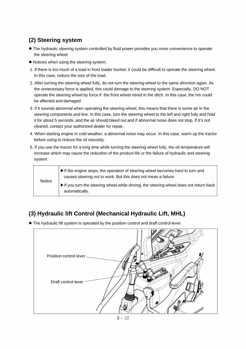
3 - 22
▶If the engine stops, the operation of steering wheel becomes hard to turn and
causes steering not to work. But this does not mean a failure.
▶If you turn the steering wheel while driving, the steering wheel does not return back
automatically.
Notice
(2) Steering system The hydraulic steering system controlled by fluid power provides you more convenience to operate
the steering wheel.
Notices when using the steering system.
1. If there is too much of a load in front loader bucket, it could be difficult to operate the steering wheel.
In this case, reduce the size of the load.
2. After turning the steering wheel fully, do not turn the steering wheel to the same direction again. As
the unnecessary force is applied, this could damage to the steering system. Especially, DO NOT
operate the steering wheel by force if the front wheel mired in the ditch. In this case, the rim could
be affected and damaged.
3. If it sounds abnormal when operating the steering wheel, this means that there is some air in the
steering components and line. In this case, turn the steering wheel to the left and right fully and hold
it for about 5 seconds, and the air should bleed out and if abnormal noise does not stop. If it’s not
cleared, contact your authorized dealer for repair.
4. When starting engine in cold weather, a abnormal noise may occur. In this case, warm up the tractor
before using to reduce the oil viscosity.
5. If you use the tractor for a long time while turning the steering wheel fully, the oil temperature will
increase which may cause the reduction of the product life or the failure of hydraulic and steering
system.
Position control lever
Draft control lever
(3) Hydraulic lift Control (Mechanical Hydraulic Lift, MHL)
The hydraulic lift system is operated by the position control and draft control lever.

3 - 23
In working by draft control
In working by position control
Draft sensorstopper
Stopper A
Positioncontrol lever
UP
DOWN
Stopper B
Draft Control
lever
① Position control
To set the position (height) of the rear implement,
move the position control lever up/down during
the engine is running. Generally, this lever is
used for tiller, fertilizer distributor, mower, rake
and other rear implements.
1.Push the position control lever forward and let
the implement down by its own weight.
2.Move up the lever to desired position, the rear
implement shell be located on the position
corresponding to the lever position.
3.To set the lowest position of the lever, Turn
stopper A counter-clockwise, move and lock the
stopper A at desired position.
② Draft control
The working depth of the implement under the
draft control is controlled automatically by the
draft load of the implement that detected from
draft load sensor bracket and transmitted to the
lift control valve. Generally, this mode is used for
the implement which receives the draft load.
In this case, operate the lever as follows.
1.Remove the draft sensor stopper of upper link
bracket.
2.Move the position control lever forward fully
(Down) and let the implement down by its own
weight.
3.The draft load to lift control valve shall be
determined according to the position of draft
control lever.
That is, the more the lever moves back (up), the
more the implement rises up by light draft
load.
4.If you want to lift the rear implement, use the
position control lever instead of the draft control
lever
Light load
Heavy load
③ Mixed control
If using above two levers in combination, mixed control is available. Set the position of the implement
first, and set the draft control lever depending on the draft load. At this time, working depth can be
controlled by draft control lever under position control.

3 - 24
④ Down speed control knob Turn the valve knob to the right to lower the
implement slowly and to the left to rise speed
faster. If turning right fully, the implement shall
be fixed and even if lowering down the position
control lever, the implement does not let down.
Tiller work : Slow in down speed
plough work : Fast in down speed
When working in hard ground, slow down the
down speed to avoid the bounding of the
implements.
▶When running on the road, turn right the down speed control knob slightly to lock.
▶When changing the blades of tiller or removing grass, stop the engine and turn the
down speed control knob to right slightly to lock.
Warning
(4) Remote control lever and Quick coupler (optional)
These levers are used to operate the hydraulic cylinder and/or motor of the implement attached to
the tractor.
Push the remote control lever forward, and the hydraulic pressure can be delivered to the left-hand coupler of the related lever and right-hand coupler shall be connected to the drain.
Each lever of the remote control valve can be operated respectively, and when operating the levers
at the same time, the one received less pressure begins to start first.
After connecting and preliminary operating the hydraulic equipment, check again transmission oil
level of the tractor.
Down speed control knob
FastSlow
Lever②
Lever①
Push
Pull
When pushing lever②
When pushing lever① When pulling lever①
When pulling lever②

3 - 25
(5) Joystick lever (optional)
※ Remote joystick lever helps to operate front loader comfortably.
When connecting hydraulic hoses, follow the instruction below.► loader down - opening ①► loader up - opening ②► bucket up - opening ③► bucket dump - opening ④
The standard of hydraulic opening is PS3/8”.
Use the adapter for hydraulic connection.
Joystick can be operated at 4 directions as shown
in the right figure.
If you move joystick diagonally, loader and bucket
shall be operated at the same time. Then, small
loads move first.
When you want to float bucket, lower the loader
and push forward the lever at floating position.
After finishing work, pull the lever and place it in
neutral position.
Loader up
Loader down
Bucket up
Bucket dump
Bucket floating<Meaning of symbols>
Locking lever(safety device)
Joystick lever
Locking lever shown in the right figure is used to
lock the joystick lever.
- Pull from the joystick : Unlock
- Push to the joystick : Lock
For further information, See section 4-4 in this manual.
▶To prevent accidents, push and lock the locking lever when you do not use joystick
lever.Warning
Lock
①
②
③
④
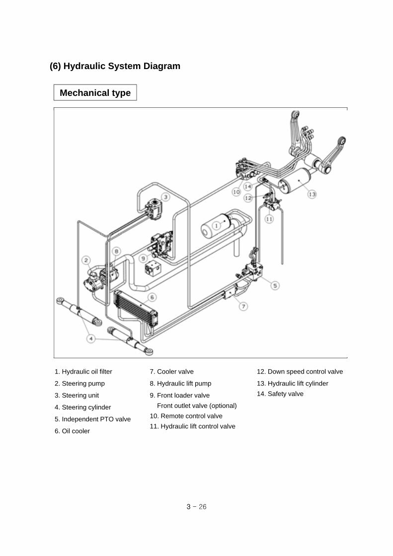
3 - 26
(6) Hydraulic System Diagram
1. Hydraulic oil filter
2. Steering pump
3. Steering unit
4. Steering cylinder
5. Independent PTO valve
6. Oil cooler
7. Cooler valve
8. Hydraulic lift pump
9. Front loader valve
Front outlet valve (optional)
10. Remote control valve
11. Hydraulic lift control valve
12. Down speed control valve
13. Hydraulic lift cylinder
14. Safety valve
Mechanical type
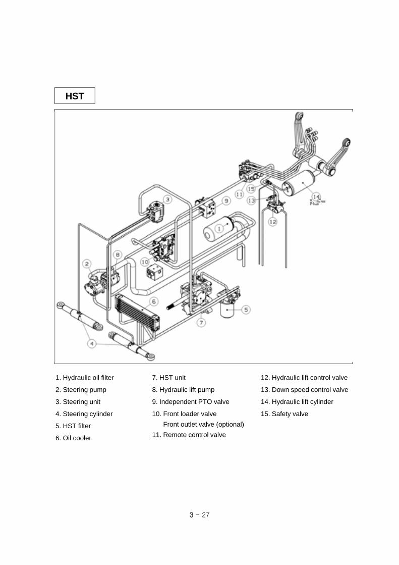
3 - 27
HST
1. Hydraulic oil filter
2. Steering pump
3. Steering unit
4. Steering cylinder
5. HST filter
6. Oil cooler
7. HST unit
8. Hydraulic lift pump
9. Independent PTO valve
10. Front loader valve
Front outlet valve (optional)
11. Remote control valve
12. Hydraulic lift control valve
13. Down speed control valve
14. Hydraulic lift cylinder
15. Safety valve

4 - 1
1. Sit in driver’s
seat and apply
parking brake
2. Place main gear shift, range gear
shift lever, shuttle lever in NEUTRAL
and PTO switch in OFF position.
3. Pull throttle lever to the
middle position of the full
throttle.
4. Turn key switch to ON
and check if engine oil
pressure indicator,
battery charging indicator,
cold start aid indicator is
ON.
5. Wait until the cold start
aid indicator is OFF.
(about 10 seconds)
6. Depress clutch pedal
fully and turn key switch
to START position. As
soon as the engine starts,
release the key switch to
ON position.
7. Check if engine oil
pressure indicator and
battery charging indicator
is OFF. If not, stop the
engine immediately and
check the problem.
8. Run engine for a few
minutes to allow engine oil
and transmission oil to warm
up.
4. Operation and Work4-1. Engine start and stop
(1) Engine start
Caution
▶Check each part before starting the
engine.
▶Check if there is some other people
around before starting.
▶Place all the levers and switches in
NEUTRAL or OFF position.
Brake pedals
Clutch pedal
Main gearshift lever
PTO switch
OFF
Key switch
OFF
ON/PRE-HEAT
Start
42
31
N
Mechanical type

4 - 2
1. Sit in the driver’s seat and apply the parking brake lever.
2. Place the range gear shift lever and HST forward/reverse pedal in NEUTRAL, and PTO switch in OFF.
HST type
Brake pedals
HST reversepedal
Throttle lever
HST forwardpedal
3. Push the throttle
lever to the middle
position of the full
throttle.
4. Turn the key switch
to “ON” and check if
engine oil pressure
indicator, battery
charging indicator, cold
start aid indicator is ON.
5. Wait until cold start
aid indicator is OFF.
(about 10~15 seconds)
Caution
▶Check each part before starting
engine.
▶Check if there is some other
people around before starting.
▶Place all the levers and switches in
NEUTRAL or OFF position.
6. Turn the key switch to
“START” position. As soon
as the engine starts,
release the key switch to
“ON” position.
7. Check if engine oil pressure
indicator, battery charging
indicator is OFF. If any these
indicators is ON, stop the
engine immediately and check.
8. Run engine a few
minutes to allow engine
oil and transmission oil to
warm up.
PTO switch
Key switch

4 - 3
(3) Engine Stop
Push the Throttle lever forward to reduce the engine speed and place the key switch on “OFF”
position to stop the engine.
Caution ▶Only start engine outdoors or in a well ventilated place, as the engine exhaust
fumes may cause sickness or death. .
▶To avoid an explosion, never use starting fluid to start engine.
▶Start the engine ONLY from the driver’s seat with depressing clutch pedal fully.
▶DO NOT start the engine by shorting across the terminals of start motor. If the
engine starts, the tractor can move suddenly.
▶ To stop the engine after finishing heavy work, run engine for 5 minutes in low
speed RPM. If you stop the engine suddenly, the engine life could be reduced.Notice
Caution
▶If not pressing the clutch pedal fully, the start safety switch does not work even if
turning the key switch to “START” position, until you press clutch all the way down.
▶The running time of start switch must be within 10 seconds and if it does not start,
stop and wait 1~2 minutes and then restart.
▶Place the PTO switch OFF when starting.
▶ When the engine is turning, do not turn the start key to “START” position.
It may cause the failure of start motor.
▶ In cold weather, carry out warming procedure. If the machine is used in the state
that the engine does not reach the normal temperature, the engine life shall be
reduced.
▶When storing the tractor in the cold weather, the battery must be removed and
stored in a cool and dry place where it is warm and is isolated from the children.
▶Allowing engine to idle for a long time will waste fuel and cause a build up of carbon.
Notice
(2) Start in cold weather
Push the throttle lever to the middle position of full throttle.
Start the engine after cold start aid indicator goes OFF. (If fitted)
If engine runs rough, push the throttle pedal down 2~3 times for a while. (Mechanical type)
If engine runs smoothly, carry out warming up for 5~10 minutes at 1500 rpm.
Use the engine oil for winter in cold weather. Refer to “Lubricants and Capacity” at the end of this
manual.
Use the diesel for winter when it is very cold weather. It is much easier to start engine.

4 - 4
1. Pull position control lever
backward to lift the implement after
starting engine.
2. Press clutch pedal fully and place
all the transmission gear levers
(main, range, shuttle lever) on
desired position.
3. Pressing brake pedals, and release parking brake lever.
4. Release clutch pedal slowly with
pressing throttle pedal slowly.
Position control lever
4-2. How to drive and how to stop
▶Release the clutch pedal slowly. If not, the transmission gear life shall be reduced
and it may cause a sudden start.Notice
Throttle pedal
Brake pedals
Shuttle lever
Clutch pedal
Throttle lever
(1) How to drive
Mechanical type
Main gear shift lever
Range gear shift lever
Parking brake lever

4 - 5
HST type
1. Pull the position control lever
back to lift the implement up after
starting engine.
2. Set the engine speed more than
1500 rev/min.
3. Place the range gear shift lever
in desired position.
5. Press the brake pedal and
release the parking brake lever.
5. Press the HST pedal slowly
forward or backward to move the
tractor.
6. If necessary, pull the cruise
control lever up for constant driving
speed.
▶ If you press the brake pedal or push down the cruise control lever, the cruise
control drive shall be stopped.
▶ For HST model, there is a switch to control engine cut-off for driver’s safety. If the
operator leaves the driver’s seat without proper action for safety, the engine shall be
stop automatically. (For further information about seat, see section 2.)
▶ When driving or working with a tractor, operate it more than 1500 rev/min.
▶ Press the HST forward / reverse pedal slowly. If you depress the HST forward /
reverse pedal hastily, It might start suddenly.
Caution
Brake pedals
HST reverse pedal
Throttle lever
HST forward pedal
Position control lever
Range gear shift lever
Parking brake lever
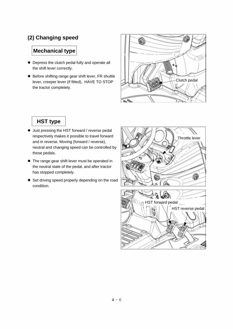
4 - 6
(2) Changing speed
Depress the clutch pedal fully and operate all
the shift lever correctly.
Before shifting range gear shift lever, FR shuttle
lever, creeper lever (if fitted), HAVE TO STOP
the tractor completely.
Mechanical type
HST type
Just pressing the HST forward / reverse pedal
respectively makes it possible to travel forward
and in reverse. Moving (forward / reverse),
neutral and changing speed can be controlled by
these pedals.
The range gear shift lever must be operated in
the neutral state of the pedal, and after tractor
has stopped completely.
Set driving speed properly depending on the road
condition.
HST forward pedal
Throttle lever
HST reverse pedal
Clutch pedal

4 - 7
(3) Emergency Stop
1. Press the clutch pedal and brake
pedals at the same time to stop the
tractor. Turn OFF the key switch.
2. DO NOT release clutch pedal until all
moving parts have stopped.
Mechanical type
3. Apply parking brake.
3. Apply parking brake.
1. Release the HST forward/reverse
pedal and press the brake pedals
immediately.
HST type
2. Pull throttle lever backward to
decrease the engine speed.
Turn OFF the key switch.
Brake pedals
Clutch pedal
Throttle lever Key switch
HST forward pedal
Throttle lever
HST reverse pedal
Brake pedals

4 - 8
1. Press the clutch and brake pedal.
Place the shuttle lever, main gear shift
lever in NEUTRAL and PTO switch to
OFF position.
3. Apply parking brake and release the
brake pedal and clutch pedal slowly.
2. Push the position control lever forward
to lower implements to the ground. Turn
key switch to “OFF” position.
(4) Stopping tractor
Caution
▶ DO NOT keep apart from the tractor in the state that the transmission gear is
placed in NEUTRAL and the parking brake is not applied. The tractor may roll.
Apply the parking brake at all times before leaving the tractor.
▶ Remove the ignition key always after stopping engine.
Mechanical type
Throttle lever
Key switch
PTO switch
1. Release the HST forward/ reverse
pedal slowly and pull the throttle lever
backward to reduce the engine speed,
and place the range gear shift lever in
NEUTRAL and PTO switch to OFF.
3. Apply parking brake and release the
brake pedal slowly.
2. Push the position control lever forward
to lower implements to the ground. Turn
key switch to “OFF” position..
HST Type
Parking brake lever
Brake pedals
Clutch pedal
Throttle lever Key switch
Brake pedals

4 - 9
▶ Connect the left/right brake pedal with brake pedal connecting pin before driving (if
fitted).
▶ Avoid a sudden start, sudden brake and sudden turning.
▶ DO NOT allow people on the tractor or on other implements.
▶ DO NOT place the baggage on the tractor or implement.
▶ Place PTO gear lever in Neutral position and put the PTO switch in “OFF” position.
▶ DO NOT use the differential lock pedal and front wheel drive (2WD use only).
▶ When traveling with implement on rear 3-point linkage, tighten the stabilizer to
avoid lateral movement.
▶ When traveling with implements installed, turn slowly by wide turning radius.
▶ While traveling, DO NOT ride your foot on the clutch pedal (if fitted) or brake pedal.
▶ While traveling, DO NOT operate any implement such as tiller, loader etc.
Caution
Position control lever
(5) Driving tractor on the road
When facing downhill, DO NOT place the gear lever in Neutral position.
When driving the tractor on a unpaved road by attaching a implement to 3-point linkage, place the
gear lever to low speed and DO NOT lift the implement up to the highest position. When driving in
the highest position, it may cause the vibration of implement and the failure of hydraulic system.
(In this case, place the position control lever on ¾ rising position of full stroke for safety.)

4 - 10
(6) Parking
Stop the tractor on a level surface, not a slope.
Disengage PTO and place all the transmission
shift levers in NEUTRAL position.
Lower the mounted implements on the ground.
Apply parking brake.
Stop engine and remove ignition key.
Before you leave the operator’s station, wait for
engine and all moving parts to stop.
Have to apply the wheel chocks when parking
the tractor on a slope unavoidably.
▶If it is necessary to park the tractor on a slope, furthermore with loaded trailer, the
tractor may roll down, even though the parking brake is applied. In this case, apply
the gear in low speed and apply the chocks or blocks to all the tire.
- Mechanical : downward slope ⇒ reverse 1 gear / upward slope ⇒ forward 1 gear.
- HST : Lowest range gear
Caution
(7) Handling Turbocharger
(if fitted)
Before accelerating or starting the tractor fitted
with the turbocharger, allow the engine to idle at
1000 rpm for about 30 seconds to ensure that
the turbocharger is correctly lubricated.
Before stopping engine fitted with the
turbocharger, allow the engine to idle at 1000
rpm for at least 5 minutes. This allows the
turbocharger and manifold to cool, preventing
deformation of the components.
After stopping engine fitted with the turbocharger,
cover the exhaust tail pipe to prevent the
turbocharger rotating in the wind, resulting in
possible damage to the bearings. The
turbocharger turbine must be prevented from
rotating freely with the engine off, as the shaft
bearings will not be lubricated.
Turbocharger
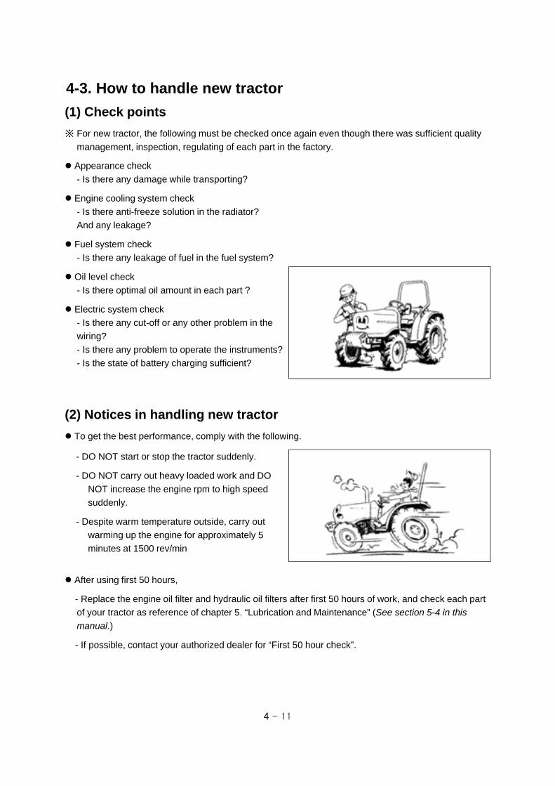
4 - 11
4-3. How to handle new tractor
(2) Notices in handling new tractor
To get the best performance, comply with the following.
- DO NOT start or stop the tractor suddenly.
- DO NOT carry out heavy loaded work and DO
NOT increase the engine rpm to high speed
suddenly.
- Despite warm temperature outside, carry out
warming up the engine for approximately 5
minutes at 1500 rev/min
(1) Check points
※ For new tractor, the following must be checked once again even though there was sufficient quality
management, inspection, regulating of each part in the factory.
After using first 50 hours,
- Replace the engine oil filter and hydraulic oil filters after first 50 hours of work, and check each part
of your tractor as reference of chapter 5. “Lubrication and Maintenance” (See section 5-4 in this manual.)
- If possible, contact your authorized dealer for “First 50 hour check”.
Appearance check
- Is there any damage while transporting?
Engine cooling system check
- Is there anti-freeze solution in the radiator?
And any leakage?
Fuel system check
- Is there any leakage of fuel in the fuel system?
Oil level check
- Is there optimal oil amount in each part ?
Electric system check
- Is there any cut-off or any other problem in the
wiring?
- Is there any problem to operate the instruments?
- Is the state of battery charging sufficient?

4 - 12
(1) 3-point linkage
4-4. Attaching equipment
1. Lift rod (LH)
2. Stabilizer
3. Lower link
4. Lift rod (RH)
5. Upper link
6. Lift rod pin
7. Upper link pin
①
④
③
⑤
②
⑥
⑦
Warning ▶Before attaching/detaching implement, place PTO switch in OFF position and PTO
gear lever in NEUTRAL ,and apply the parking brake.
▶When attaching/detaching implement, make sure to assemble and tighten the
connecting parts correctly.
▶if the tractor is used to tow heavy loads, always use the approved drawbar or hitch
to avoid injury. Never connect to lower link or upper link of 3-point linkage. If not, it
may cause tipping or turnover.
▶DO NOT connect the implements that require more power than can be generated
by your tractor.
▶Never stand between implement and tractor when backing up.
When attaching the implement, comply with the followings.
1. Set the implement upright on a level surface and approach the implement in reverse.
2. Stop the tractor on attaching position and apply the parking brake.
3. Connect the lower link(3) to implement and insert firmly the lock pin. (left, right)
4. Connect the upper link(5) to implement and insert firmly the lock pin. Wide adjustable range of the
upper link provides you easier attachment.
5. Fix the implement firmly with stabilizer(2).(left, right).

4 - 13
Adjustment range
Lift rod
430~540 mm(16.9 ~ 21.3in)
Upper link
480~ 700 mm(18.9 ~ 27.6in)
① Adjustment of Lift rod and Upper link Do not adjust the lift rod and upper link over the
described range as below.
For lift rod (RH)
- Lift up the lift rod handle and turn left or right to
adjust the length.
- Lock the lift rod handle to the lower part after
adjusting.
For upper link
- Lift up the lock spring to release the handle and
turn the upper link by using the handle.
- Apply the lock spring after adjusting.
Lift rod (LH)
Lift rod (RH)
Upper link
Lift rod handle
② Adjustment of stabilizer’s length
ⓐ Check chain type
Turn the knob(2) to adjust the length of the
stabilizer(1). After the adjustment , let it tightened
firmly by fixing nut(1).
▶When adjusting the stabilizer’s
length, adjust the implement’s
swinging clearance to be
20~40mm (0.79~1.57 in.) left
and right.
Notice
①
③
②

4 - 14
③ Reference of implement installation part
ⓑ Telescopic type
Pull up the link pin (1) and adjust the stabilizer by
moving the pin in stabilizer holes.
After the adjustment, insert the pin into the
desired hole and let it tightened firmly by locking
spring.
▶When adjusting the stabilizer’s
length, adjust the implement’s
swinging clearance to be
20~40mm (0.79~1.57 in.) left
and right.
Notice
①
Telescopic stabilizer
19(0.74)
A BC
(Max) G H J L N
CAT.119.3
(0.75)683
(26.8)12
(0.47)39
(1.53)35
(1.53)22.4
(0.88)22
(0.86)44.5
(1.75)69
(2.71)76
(2.99)44
(1.73)
Unit : mm(unit : inch)
D(Min) K
E(Max)
F(Min)
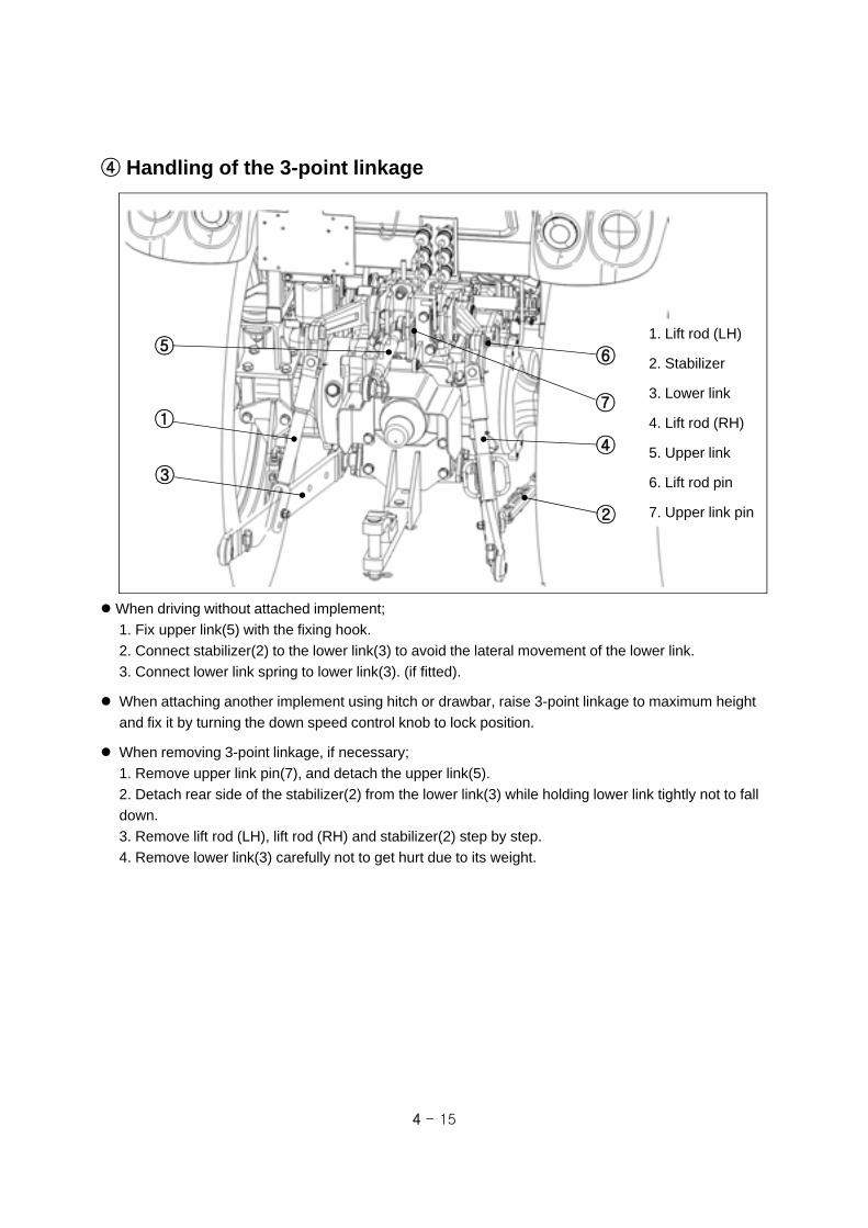
4 - 15
④ Handling of the 3-point linkage
When driving without attached implement;
1. Fix upper link(5) with the fixing hook.
2. Connect stabilizer(2) to the lower link(3) to avoid the lateral movement of the lower link.
3. Connect lower link spring to lower link(3). (if fitted).
When attaching another implement using hitch or drawbar, raise 3-point linkage to maximum height
and fix it by turning the down speed control knob to lock position.
When removing 3-point linkage, if necessary;
1. Remove upper link pin(7), and detach the upper link(5).
2. Detach rear side of the stabilizer(2) from the lower link(3) while holding lower link tightly not to fall
down.
3. Remove lift rod (LH), lift rod (RH) and stabilizer(2) step by step.
4. Remove lower link(3) carefully not to get hurt due to its weight.
1. Lift rod (LH)
2. Stabilizer
3. Lower link
4. Lift rod (RH)
5. Upper link
6. Lift rod pin
7. Upper link pin
①
④
③
⑤
②
⑥
⑦

4 - 16
(2) Power take-off (PTO) shaft
PTO gear(s)
PTO / Engine speed
Revolution direction
Ground clearance
1 2(optional) 3(optional)
540 / 2409 rpm 750 / 2375 rpm 1000 / 2381 rpm
Clockwise (When looking at PTO shaft end)
Shaft dimension(Unit : inch)
(3.0 in)
(1.5 in)
(0.34 in)
(1.1 in)
(1 3
/8 in
)
= Tire radius + 17.5mm (0.69 in.)
① Safety precautions
When PTO shaft is rotating, NEVER APPROACH the shaft.
Check if PTO shield is attached correctly. If the shield is removed or damaged, replace it with a new
one.
Suitable Clothes & Protect Entanglement :
When checking or attaching implement to the PTO
shaft, wear tight fitting clothes and safety
equipment instead of loose or long clothes. Also,
slippers, high heel shoes are not suitable. Wear
the suitable clothes.
Warning ▶Do not approach the rotating shaft such as PTO shaft or cooling fan, especially,
with loose clothing and long clothes. The entanglement in rotating shaft can cause
serious injury or death.
▶Stop the engine and be sure PTO shaft is stopped before getting near it.
Refer to the followings about PTO shaft dimension.

4 - 17
② Attaching PTO drive shaft
When attaching implements with power take-off drive shafts, refer to the drawings as below.
After installing implements, check the inclination of the drive shaft, and interference with PTO safety
cover and other structure. The stiff inclination of the drive shaft make a loud noise and may cause a
failure of the driveline.

4 - 18
HitchFixing pin
Hitch pin
(3) Hitch and Drawbar (optional)
When attaching towing equipments, use the hitch
or drawbar. DO NOT use the 3-point linkage or
other parts. If so, the tractor could turnover.
Insert the hitch pin and snap pin correctly after
attaching/detaching equipment.
DO NOT exceed the maximum permissible
vertical and horizontal load as below.
Snap pinDrawbarw/clevis
① Hitch
Vertical load : 900kg (1984 lbs)
Horizontal load : 3600kg (7937 lbs)
② Drawbar (w/clevis)
It is used to tow the equipments having 2 axles.
It is available to adjust the length of the draw bar
after removing snap pin and lock-pin in the right
figure. After adjusting, assemble the pins firmly.
Vertical load : 400kg (when pulled) (882 lbs)
575kg (when pushed) (1268 lbs)
Horizontal load : 2800kg (6173 lbs)
▶ Pulling from the tractor rear axle or any point above the axle may cause the tractor
to overturn. Use always the drawbar or hitch for pulling work.
▶ Do not tow equipment without brakes, weighing more than twice the tractor weight.
▶ When locking the hitch or drawbar with pin after aligning to the towing equipment,
apply the parking brake and stop the engine.
▶ Before transporting equipment on public roads, make sure you comply with your
local traffic regulation.
Caution
Technically permissible towable mass(es) are as below according to type of coupling.
Hitch Drawbar (w/clevis)
Unbraked towable mass 1800kg 1400kg
Independently braked towable mass 3600kg 2800kg
Inertia-braked towable mass 3600kg 2800kg
Hydraulic or pneumatic braked towable mass N/A N/A
Hitch pin

4 - 19
(4) 7-Pole connector (optional)
The one of the standard 7-pole trailer connectors is provided and is mounted at the rear of the tractor.
The connections of the 7-pole connector (viewed from the rear of the tractor) are as follows;
EC Version
Pin No. Function
1 Left turn signal light
2 NA
3 Ground (Earth)
4 Right turn signal light
5 Side light
6 Brake light
7 Side light
ASAE Version
Pin No. Function
1 Ground (Earth)
2 Working light
3 Left turn signal light
4 Brake light
5 Right turn signal light
6 License number plate light
7 Auxiliary
7-Pole Connector (EC) 7-Pole Connector (ASAE)

4 - 20
(5) Technically maximum permissible mass
When working with front loader or rear heavy loaded attachments installed to the 3-point linkage,
install ballast weights on the counter-part axle to maintain the front and rear weight balance of the
tractor. If not, front or rear axle can be strained by the overloaded weight.
When working with the front loader, place the attached rear weight to the highest position and turn
the down speed control knob to the “lock” position.
DO NOT exceed the total maximum permissible mass and/or permissible maximum mass on
each axle declared by manufacturer as below, even if the load capacity of the tire is sufficient.
If the load capacity of the tires is lower than maximum permissible mass on each axle, the
maximum mass on each axle must be loaded under the load capacity of the tire.
Check the load capacity of the tires.
All models Remarks
Technically total maximum permissible mass
3008kg (6631 lb)
It depends on the load capacity of the tires. (See next page)Front axle (*) 1320kg (2910 lb)
Rear axle 2105kg (4641 lb)
▶ Maximum permissible mass is measured with only the front or rear wheels on the
scales inclusive of ballasts and with mounted equipments in the raised position.
▶ Do not exceed the maximum permissible mass above and/or the load
capacity of the tires. Overloaded operation may invalidate the warranty.
▶ DO NOT change the setting pressure of the relief valve arbitrarily to increase the
lift capacity of the front loader or 3-point linkage. It can cause fatal damage to the
hydraulic system and front axle.
Caution
* includes front mounted equipment or loader in the raised position but without load in the bucket.
Restrict operation : In case of driving speed does not exceed 8km/h (5 mph) and standard
front/rear wheel track (See page 4-22), Intermittent maximum permissible load of the front axle can
be ;
1995kg (4398 lb) for all models ; Have to check the load capacity of the tires. (See next page).

4 - 21
(6) Tires and Load capacity
Axle No.(*)
TiresStandard tire air pressure
(kg/cm2)Load capacity (x2)
(kg)Maximum mass(es)
(kg)
1 7-16 4PR 1.8 (180 KPa, 26 psi) 810 (1786 lb)2915(6426 lb)
2 11.2-24 8PR 2.4 (240 KPa, 35 psi) 2220 (4894 lb)
1 8-16 4PR 1.6 (160 KPa, 23 psi) 950 (2094 lb)3008(6631 lb)
2 12.4-24 6PR 1.6 (160 KPa, 23 psi) 2180 (4806 lb)
1 8-18 4PR 1.6 (160 KPa, 23 psi) 1040 (2293 lb)3008(6631 lb)
2 13.6-24 8PR 2.2 (220 KPa, 32 psi) 3230 (7121 lb)
1 9.5-16 6PR 2.2 (220 KPa, 32 psi) 1450 (3197 lb)3008(6631 lb)
2 13.6-24 8PR 2.2 (220 KPa, 32 psi) 3230 (7121 lb)
1 8.3-20 6PR 2.4 (240 KPa, 35 psi) 1420 (3130 lb)3008(6631 lb)
2 12.4-28 6PR 1.6 (160 KPa, 23 psi) 2550 (5622 lb)
Optional Tire
1 200/70R16 2.4 (240 KPa, 35 psi) 1340 (2954 lb)3008(6631 lb)
2 300/70R20 1.6 (160 KPa, 23 psi) 2120 (4674 lb)
1 250/75R16 4.2 (420KPa, 60 psi) 2800 (6173 lb)3008(6631 lb)
2 340/80R24 3.5 (350KPa, 50 psi) 4360 (9612 lb)
(*) 1 : Front axle, 2 : Rear axle

4 - 22
(7) Adjusting Wheel tracks and
tire replacement
If the front wheel track is adjusted, check the
clearance between tires and tractor body case
by case. If necessary, the steering angle must
be adjusted.
(See page 4-27 in this manual.)
When adjusting rear wheel track, check the
radial and lateral clearance between rear tire
and tractor chassis as below.
- A : 30mm (1.2 in) (Minimum)
- B : 15mm (0.6 in) (Minimum)
Depending on rim or disk type, the front and
rear wheel tracks may vary.
“A”
“B”
① Front wheel track- 8.3-20 6PR with rim & disk (W7x20)
- Standard wheel track : See next page.
② Rear wheel track- 12.4-28 6PR with rim & disk (W10x28)
- Standard wheel track : See next page.
▶ When adjusting the wheel track, pay attention to the direction of tire lugs. if it shows “/\” shape when looked behind, it is correct.
▶ Actual settings may vary depending on the brand of the rim and type of tire.
Notice

4 - 23
① Front wheel track – 8.3-20 6PR with rim & disk (W7x20) Unit : mm (inch)
1444(56.9in)
N/A
N/A
N/A
(Standard track)
1244(49.0in)
1391(54.8in)
1336(52.6in)
1283(50.5in)

4 - 24
② Rear wheel track – 12.4-28 6PR with rim & disk (W10x28) Unit : mm (inch)
1140(44.9in)N/A
N/A
N/A
N/A
(Standard track)
1194(47.0in)
1252(49.3in)
1306(51.4in)

4 - 25
① Safety precautions
Multi-functional joystick lever provides you more convenient operation for front-end loader.
When operating the tractor with front-end loader,
The center of gravity of the tractor may be higher,
and the stability of the vehicle may be worse than
unattached vehicle.
-. DO NOT drive fast on a traffic road. The rolling
or tipping of the tractor can be happened easily.
-. When loading/unloading the bucket on a slope,
move the tractor straight against the slope.
-. DO NOT try to approach a stiff slope.
-. Attach the ballast weight on the 3-point linkage
to prevent the overload of the front axle, and to
improve the stability of the vehicle.
When working with front-end loader, the front
visibility of the tractor may be worse than
unattached vehicle. Have to observe people and
other vehicles around the tractor.
DO NOT allow to stay people under the front-end
loader.
DO NOT allow people on the bucket.
Only install a front-end loader with a parallel
guidance system and use it all the time; this
system will ensure that the load in the bucket will
remain horizontal, regardless of the height of the
lifting booms.
▶After using the front-end loader, lock the joystick lever to prevent the accident.
(if fitted)
▶When leaving the tractor, lower down the front-end loader on ground.
Warning
(8) Using Front-end loader (optional)
Locking lever(safety device)
Joystick lever
Lock
▶Have to strictly observe the following precautions;
- Do not lift the front-end loader to a height from which objects may fall or roll onto
the driver.
- Use always the correct attachment (grab forks, buckets.. etc) for the specific task
to perform and ensure that the load is securely kept in place.
Warning

4 - 26
② Attaching points for Front-end loader
When attaching the front-end loader for all models, refer to the drawings as below.

4 - 27
1) Loosen the locking nut on both sides.
2) Connect the front hook of the tractor to the crane
by using specified wire. And, lift up the front axle
off the ground sufficiently.
3) Lift up one side of the front axle fully and turn the
steering wheel to the left and right with checking
that the clearances between tire and other parts
are over 20mm (0.79 in.) at least.
4) At this time, set each steering stopper of the both
sides to be contacted with the cast. Check all the
possible interferences by combinations of the
steering and oscillation of the front axle.
5) Tighten the locking nuts of the each side.
(9) Adjusting Steering angle
If the front wheel track is adjusted or front tires are replaced with new tires having bigger diameter or
width, or one of the front equipments is attached, the steering angle must be adjusted as below.
▶DO NOT shorten the length of the steering stopper rather than factory condition.
If the stopper does not contact at maximum steering condition, it can damage the
steering cylinder or tie-rod.
Notice
Steering stopper

4 - 28
(10) Recommended maximum specification of implements
When attaching implements to the tractor, refer to the followings recommended as maximum
specification of each implement. DO NOT attach bigger implements then this specification. For other
implements, contact your authorized dealer.
No. Implements SpecificationXR45 /
XR45HSTXR50 /
XR50HSTXR60
1 Front loaderMax lift capacity
(Bucket pivot point)1134 kg(2500 lb)
1197 kg(2639 lb)
1197 kg(2639 lb)
2 Rotavator Max tilling width1650 mm
(65 in)1750 mm(68.9 in)
1850 mm(72.8 in)
3 Backhoe Max digging depth2280 mm(89.8 in)
2280 mm(89.8 in)
-
4 Rotary cutter Max working width1829 mm
(72 in)2134 mm
(84 in)-
5 Mid mower Max working width1829 mm
(72 in)1829 mm
(72 in)-
6 Landscape lake Max working width1524 mm
(60 in)1829 mm
(72 in)-
7 Box blade Max working width1524 mm
(60 in)1829 mm
(72 in)-
8 Rear blade Max working width1829 mm
(72 in)2134 mm
(84 in)-

4 - 29
▶ The filters are made of specially treated media with a rubber sealing strip bonded
around the sides. Take care not to damage the element during installation.Notice
Warning
▶The charcoal filters do not guarantee full protection against all pesticides.
▶These specific filters only reduce the harmful effects of these products. As a result,
operator has to comply with the safety rules recommended for using each single
product. Wear the protection clothing, globes, mask, etc before operating in that
area.
▶DO NOT operate the tractor in heavy pesticides or other hazardous spraying area.
Caution
▶Do not use these filters during other work, as they will quickly become clogged with
dust. When replacing the charcoal filters at the end of spraying work, return them to
the original packaging and make sure that they are carefully sealed.
▶The charcoal filters last for approximately 50 hours of work. They must, however,
be replaced each year. If, when working with pesticides, toxic odors are noted, stop
the work immediately and replace the filters with new one.
▶These filters must never be washed or cleaned with compressed air. Discarded
filters must not be thrown away. Take disposed filters to authorized collection points.
② Cleaning the cabin inside
Protective clothing worn when handling the sprayer with pesticides or when carrying out external
works, must be removed and stored away carefully before re-entering the cabin.
After working with pesticides, ventilate the cabin and clean the inside parts (interior trim, panels, step,
etc) of the cabin with clean damp cloth to remove the chemical residue.
Cabinair filters
Bolt
Filtercover
① Cabin air filters (LH/RH)
When operating with pesticides, cabin air filters
should be replaced with specific charcoal filters.
Contact your authorized dealer.
In additional, you should wear the protective
clothing, globes, mask, etc before operating in
such a hazardous spraying area.
These filters must only be fitted when working
with pesticides and replaced with the normal
paper filters at the end of work.
4-5. Working in hazardous area Level of protection against hazardous substances : For cabin model, it provides protection
against hazardous substances according to EN15695-1:2009 (Category 2). But it can provide only
dust protection level by pressurizing air in the cabin with air filters. Do not use the tractor with crop
sprayers in hazardous area. If unavoidable, comply with the following instruction.

4 - 30
4-6. Driving speed
The driving speed of tractor or the revolution speed of PTO depends on the work, tire and ground
condition. For safety, operate the tractor at suitable speed.
Table of driving speed (unit : Km/h -> Mile/h)
Note) Engine rated speed : 2600 rev/min, Dynamic load radius : 610mm (24.0 in.)
XR45 / XR50 / XR60
① Standard speed (creeper off)
Range gear
1 2 3 4
Main gear
1 2 3 4 1 2 3 4 1 2 3 4 1 2 3 4
Forward 1.18 1.40 1.65 2.21 2.67 3.17 3.73 4.99 5.91 7.01 8.24 11.0 15.3 18.1 21.3 28.6
(mph) (0.73) (0.87) (1.02) (1.37) (1.66) (1.97) (2.32) (3.10) (3.67) (4.36) (5.12) (6.86) (9.51) (11.3) (13.3) (17.8)
Reverse 1.05 1.24 1.46 1.96 2.37 2.82 3.31 4.43 5.25 6.22 7.31 9.79 13.6 16.1 18.9 25.4
(mph) (0.65) (0.77) (0.91) (1.22) (1.48) (1.75) (2.06) (2.75) (3.26) (3.87) (4.54) (6.06) (8.44) (10.0) (11.8) (15.8)
Range gear
1 2 3 4
Main gear
1 2 3 4 1 2 3 4 1 2 3 4 1 2 3 4
Forward 0.18 0.22 0.26 0.34 0.42 0.49 0.58 0.78 0.92 1.09 1.29 1.72 2.39 2.83 3.33 4.46
(mph) (0.11) (0.14) (0.16) (0.21) (0.26) (0.31) (0.36) (0.48) (0.57) (0.68) (0.80) (1.07) (1.48) (1.76) (2.07) (2.77)
Reverse 1.05 1.24 1.46 1.96 2.37 2.82 3.31 4.43 5.25 6.22 7.31 9.79 13.6 16.1 18.9 25.4
(mph) (0.65) (0.77) (0.91) (1.22) (1.48) (1.75) (2.06) (2.75) (3.26) (3.87) (4.54) (6.06) (8.44) (10.0) (11.8) (15.8)
② Optional speed (creeper on)
XR45 / XR50 / XR60
Note) Engine rated speed : 2600 rev/min, Dynamic load radius : 610mm (24.0 in.)
Mechanical Type

4 - 31
HST Type
Driving speed (unit : Km/h -> Mile/h)
Range gear 1 2 3
Forward0~5.8
(0~3.6)0~13.1(0~8.1)
0~30.1(0~18.7)
Reverse0~5.8
(0~3.6)0~13.1(0~8.1)
0~30.1(0~18.7)
XR45HST / XR50HST
Note) Engine rated speed : 2600 rev/min, Dynamic load radius : 610mm (24.0 in.)

5 - 1
For safety, the hood must be closed and
correctly latched before operating the tractor.
The hood is hinged at the rear and a gas
cylinder is attached to provide easy access to
the engine for check and maintenance.
To open the hood, push hood opening knob and
lift the hood upward.
To close the hood, pull the hood and push it
down to locking position slightly.
5-1. Access for maintenance
① Opening Hood
Hood opening knob
▶ After the engine has stopped completely, you have to open the hood for checking.
▶ If you open the hood while the engine is running, it can cause serious damage by the intended or unintended access to the rotating shaft, pulley, V-belt, cooling fan of the engine or engine application parts. BE CAREFUL.
Caution
5. Lubrication and Maintenance
The jacking points for maintenance is depending
on serviced parts case by case. Do not hesitate
to contact your authorized dealer for asking.
Do not use the front axle assembly or steering
linkage and cylinder for jacking point. These
components have some rotating pivots and/or
does not have enough structural strength.
For general maintenance, use flat surface under
the engine frame end or bumper for jacking point,
and connect additionally hoist to the front towing
hook for safety.
For rear jacking points, flat surface under the
rear axle housing is recommended, and
additionally use the top-link bracket and its pin
for lifting point after removing the top-link.
② Jacking points
Front jacking point
Front towing hook
▶ When lifting the rear of the tractor, apply chocks to the slots between front axle and engine frame symmetrically to prevent the rolling of the front axle.
Caution
Rear jacking point
Rear jacking point
Top link pin
Top link
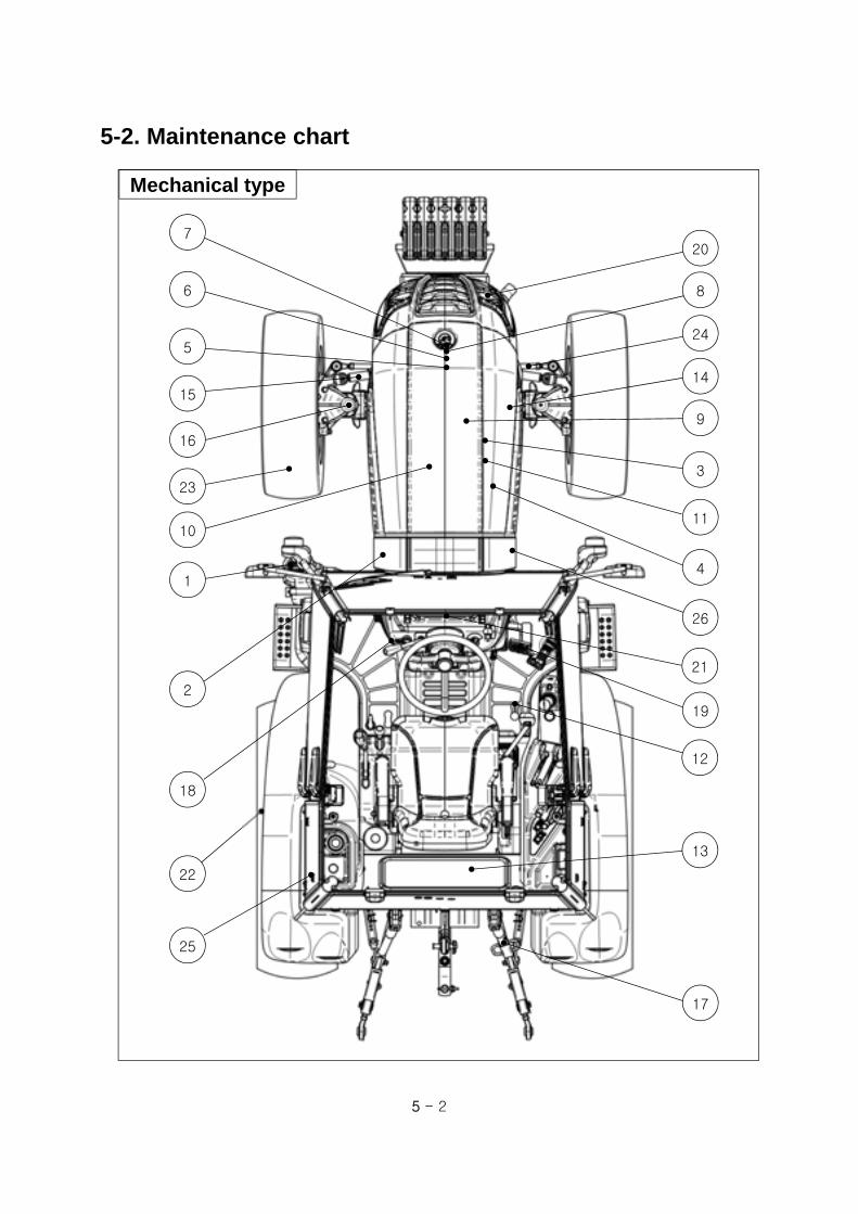
5 - 2
5-2. Maintenance chart
8
9
14
3
4
11
12
13
19
17
7
6
5
23
10
15
2
22
1
18
21
16
20
26
25
24
Mechanical type

5 - 3
★ First Replacement ● Replacement ▲ Check, Adjustment and Supply ■ Clean up
No. Checking Parts Page No.Check period (hr)
Daily 50 300 600 2-year
1 Fuel tank 5-10 ▲
2 Fuel filter 5-24 ▲ ●
3 Engine oil 5-9, 5-19 ▲ ●
4 Engine oil filter 5-7, 5-19 ★ ●
5 Engine coolant 5-12, 5-26 ▲ ●
6 Radiator screen 5-13, 5-16 ▲ ■
7 Air cleaner 5-12, 5-17, 5-22 ▲ ■ ●
8 Battery 5-17 ▲
9 Engine belt tension 5-21 ▲ ●
10 Valve clearance 5-24 ▲
11Nozzle injection
pressure5-24 ▲
12 Hydraulic oil filter 5-7, 5-20 ★ ●
13 Transmission oil 5-17, 5-23 ▲ ●
14 Front axle oil 5-17, 5-23 ▲ ●
15 Steering cylinder 5-16 ▲
16Front axle holder &
Steering arm5-16 ▲
17 3-Point linkage 5-16 ▲
18 Clutch pedal play 5-14 ▲
19 Brake pedal play 5-14 ▲
20Turn signal lights,
Lights, Horn5-11 ▲
21Instrument panel &
Indicators5-10 ▲
22 Bolts and Nuts 5-14 ▲
23 Tire air pressure 5-13 ▲
24 Toe-in 5-22 ▲
25 Cabin air filter 5-18, 5-25 ■ ●
26 Hydraulic hoses 5-17 ▲

5 - 4
8
9
14
3
4
11
12
13
18
17
7
6
5
23
10
15
2
22
1
19
21
16
20
26
25
24
HST type

5 - 5
★ First Replacement ● Replacement ▲ Check, Adjustment and Supply ■ Clean up
No. Checking Parts Page No.Check period (hr)
Daily 50 300 600 2-year
1 Fuel tank 5-10 ▲
2 Fuel filter 5-24 ▲ ●
3 Engine oil 5-9, 5-19 ▲ ●
4 Engine oil filter 5-7, 5-19 ★ ●
5 Engine coolant 5-12, 5-26 ▲ ●
6 Radiator screen 5-13, 5-16 ▲ ■
7 Air cleaner 5-12, 5-17, 5-22 ▲ ■ ●
8 Battery 5-17 ▲
9 Engine belt tension 5-21 ▲ ●
10 Valve clearance 5-24 ▲
11Nozzle injection
pressure5-24 ▲
12 Hydraulic oil filter 5-7, 5-20 ★ ●
13 Transmission oil 5-17, 5-23 ▲ ●
14 Front axle oil 5-17, 5-23 ▲ ●
15 Steering cylinder 5-16 ▲
16Front axle holder &
Steering arm5-16 ▲
17 3-Point linkage 5-16 ▲
18HST Pedal
Neutral state5-15 ▲
19 Brake pedal play 5-14 ▲
20Turn signal lights,
Lights, Horn5-11 ▲
21Instrument panel &
Indicators5-10 ▲
22 Bolts and Nuts 5-14 ▲
23 Tire air pressure 5-13 ▲
24 Toe-in 5-22 ▲
25 Cabin air filter 5-18, 5-25 ■ ●
26 Hydraulic hoses 5-17 ▲

5 - 6
5-3. Lubricants and Capacity
Lubricants Capacity International StandardRecommended products
Engine coolant
(Radiator)
6.1 L
(1.6 U.S.gals.)ASTM D5216
Soft water (50%) +
Anti-freeze (50%)
Fuel47 L
(12.4 U.S.gals.)ASTM D975 No.2
Low Sulfuric
Diesel Fuel
Engine oil
(Crank case)
7.0 L
(1.9 U.S.gals.)
API CF-4 or CG-4
Winter : SAE 10W/30
Summer : SAE 20W/40
Spring/ Fall :
SAE 15W/40, SAE 20
KIXX DL(Manufacturer :
GS Caltex)
Transmission oil
(common use for
hydraulic lift and
steering system)
43 L
(11.4 U.S.gals.)
API GL4
ISO VG 46/68
LSTH570
( Manufacturer :
GS Caltex or S-OIL
TOTAL Co. Ltd.)
Front axle oil8 L
(2.1 U.S.gals.)
API GL4
SAE 80W
EPK 80W90
(Manufacturer :
S-OIL TOTAL Co. Ltd.)
Grease
(Front axle holder,
Steering cylinder pin,
3-point linkage, etc.)
Proper
amountNLGI 2
RECOMMENDED OIL VISCOSITIES
The correct engine oil viscosity grade is dependent upon ambient temperature. Refer to the chart
below when selecting oil for your tractor engine.
In areas where prolonged periods of extreme temperatures are encountered, local lubricant practices
are acceptable ; such as the use of SAE 5W 30 in extreme low temperatures or SAE 50 in extreme
high temperatures.
StartingTemperature
( )
OilViscosity
-30(-22)
-25(-13)
-20(-4)
-15(-5)
-1014)
-5(23)
0(32)
-10(50)
20(68)
30(86)
40(104)
SAE 10W-30
SAE 15W-40
SAE 5W-20
5 - 7
After using first 50 hours, contact your authorized dealer for maintenance if possible.
- Replace engine oil filter. (⇒ Refer to Every 300 hour check. See page 5-19)
- Replace hydraulic oil filter. (⇒ Refer to Every 300 hour check. See page 5-20)
- Check transmission / rear axle / hydraulics oil level
- Check front axle oil level
- Check and adjust parking brake
- Check torque of exhaust manifold bolts
- Check and adjust V-belts and tension
- Tighten all cooling system hose connections
- Check torque of safety cab or frame mounting bolts
- Check torque of front end weight clamp bolts (Where fitted)
- Check torque of wheel bolts and nuts
- Check tire pressures and condition
- Clean radiator, oil cooler and A/C condenser cores (Where fitted)
- Check radiator coolant level and specific gravity
- Check clutch pedal free play
- Check brake adjustment and pedal equalization
- Lubricate all grease fittings
- Neutral start switches operative
5-4. First 50 hour check

5 - 8
5-5. When the warning indicator lights(1) Drain water from Fuel filter
1. Loosen the drain plug and drain water inside of
the filter. (Approx. 150cc(9.1 in³))
2. Tighten the drain plug and bleed the air from the fuel filter. (See page 5-27)
Drain plug
BodyElement
O-ring
Fuel filter sensor
Fuel filter warning indicator

5 - 9
Check the following check points before using to avoid a failure.
5-6. Check before starting (Daily check)
Wheel bolts and tightening of
each part
Brake, Clutchoperation
Amount ofengine coolant
Damage of Headlights, Turn signal lights,
Horn etc.
Fuel amount
Cleanness of radiator screen
Amount ofEngine oil
Operation of Indicators
Tire air pressureand damage
Condition of aircleaner primary
element
Checking oil level
- Check oil level before starting engine or at 5
minutes later after stopping engine.
- Check If the oil is between MAX and MIN mark of
the oil gauge. If necessary, add new oil.
- It must only be performed while the engine is
stopped.
Season Temperature Lubricant No.
Winter-20 ~ 0
( -4 ~ 32 )SAE 10W/30
Spring/Fall
0 ~20( 32 ~ 68 )
SAE 15W/40, SAE20
Summer≥20≥68
SAE 20W/40
(1) Engine oil
Oil capacity : 7.0 L ( 1.9 U.S.gals. )
Using Engine oil
- Diesel engine oil ; API CF-4 or CG-4.
Select engine oil according to the temperature
as shown in the right table.

5 - 10
(2) Fuel tank
① Using Fuel
Use low sulfuric diesel.
If contaminants like water or dusts are mixed in
the fuel, it may cause a severe damage to the
engine. To fill the tank, the fuel storage facility
must be equipped as shown in the figure. If
possible, fill the tank at the gas station.
② Using Diesel for winter
General diesel fuel tends to generate paraffin
dregs In winter time which may cause a bad
engine start. Thus, it is recommended to use
diesel for winter in winter time.
If the ambient temperature is below -15°C(5 ),
it is advised to mix diesel with kerosene as
shown on the right.
③ Checking Fuel level
Check the fuel gauge and if it’s not sufficient, fill the fuel tank with fuel.
Capacity : 47L (12.4 U.S.gals.)
▶If the engine stops after finishing work, fill the tank fully.
As the temperature drops down, the humidity in the fuel tank is condensed and may
mix with the fuel.Notice
(3) Instrument panel & Indicators
Turn the key switch to ON position and check if
the engine oil pressure indicator and battery
charging indicator are ON.
If the indicators are not OFF after starting engine,
Contact your authorized dealer for check.
Temp.≥ -15(5 )
≤-15(5 )
Fuel100% Diesel fuel
for winter
20% kerosene
added
DrumImpurities
Battery chargingindicator
Engine oil pressure indicator

5 - 11
Illuminating Lights
Headlights (low beam / high beam)
turn signal lights / work lights (front)
turn signal lights (rear)
Brake lights / tail lights
Work light(s)
Instrument panel light
Warning indicators
Light bulb specification
12V 55W / 60W
12V 21W / 5W
12V 21W
12V 21W / 5W
12V 27W (Grille) / 37.5W (Cab)
LED
LED
(4) Turn signal lights, Lights and Horn
Check the operation status of light, turn signal lights, horn etc.
▶Use the bulb of rated capacity.
▶In case of using the improper bulb, it may cause a failure of electric systemNotice
Horn switch
Turn signallight switch
Light switch
If the light is OFF suddenly when operating the switch, check the problems as followings.
1. Check the relating fuse in the fuse box.
2. Check the light bulb. If necessary, replace it by a new one as referring to below.
Indoor light (Cabin only) 12V 10W
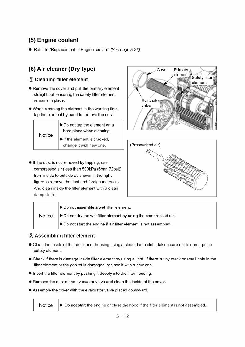
5 - 12
▶Do not assemble a wet filter element.
▶Do not dry the wet filter element by using the compressed air.
▶Do not start the engine if air filter element is not assembled.
Notice
② Assembling filter element
Clean the inside of the air cleaner housing using a clean damp cloth, taking care not to damage the
safety element.
Check if there is damage inside filter element by using a light. If there is tiny crack or small hole in the
filter element or the gasket is damaged, replace it with a new one.
Insert the filter element by pushing it deeply into the filter housing.
Remove the dust of the evacuator valve and clean the inside of the cover.
Assemble the cover with the evacuator valve placed downward.
▶ Do not start the engine or close the hood if the filter element is not assembled..Notice
If the dust is not removed by tapping, use
compressed air (less than 500kPa (5bar; 72psi))
from inside to outside as shown in the right
figure to remove the dust and foreign materials.
And clean inside the filter element with a clean
damp cloth.
▶Do not tap the element on a
hard place when cleaning.
▶If the element is cracked,
change it with new one.
Notice
(6) Air cleaner (Dry type)
① Cleaning filter element
Remove the cover and pull the primary element
straight out, ensuring the safety filter element
remains in place.
When cleaning the element in the working field,
tap the element by hand to remove the dust
Cover Primary element
Evacuatorvalve
Safety filter element
(5) Engine coolant
Refer to “Replacement of Engine coolant” (See page 5-26)
(Pressurized air)

5 - 13
(7) Cleaning of Radiator and
Radiator screen
Remove dust or dry grass stuck to the radiator or
radiator screen daily.
When cleaning the radiator with water, let water
flow from the fan side.
▶ If there are lots of foreign materials such as dry grass stuck to the radiator screen,
the cooling efficiency will be reduced and the engine can be overheated.
▶ Clean the radiator only while the engine is stopped.
Caution
Low Good Exceed
② Standard air pressure - See section 4-4-(6), “Tires and Load capacity” in this manual.
▶ It is not allowed to remove/attach or change the tire arbitrarily.Carry out the work in the tire repair center equipped with a expert and special safety tools.
▶ When checking tire pressures, keep the body away from the valve mechanism orcap.
▶ The tire pressures vary depending on the load weighing on the axles.
Caution
(8) Tire air pressure and damage
① Check
Check the air pressure or the damage of the tires
daily. Always use the correct pressure for each
axle, and If the tire is damaged, change it with a
new one.
Ensure tire pressures are not lower than the
correct values, to prevent ;
- blown tires;
- bead wear;
- internal damage;
- irregular wear and short service life.
Do not over-inflate the tires, as this may lead to damage in the event of impact and, in extreme
conditions, the tire rim may be deformed or the tire may burst.
Radiator screen

5 - 14
(9) Tightening state of bolt and nut of each part
Check if the bolts or nuts of each part are loosened and if loosened, tighten it again.
Especially, check the bolts and nuts of the tires before starting engine, if necessary, tighten them.
(10) Adjustment of Clutch pedal
play (Mechanical type)
Normal distance : 20~30mm (0.79~1.18 in.)
if the distance is over 20mm (0.79 in.),
adjust it as below.
1. Loosen locking nut and turn adjuster to adjust.
2. If the adjuster is tightened, the pedal play shall be
decreased, and if adjuster is loosened, it shall be
increased.
3. After adjusting the pedal play, tighten the locking
nut.
4. Check if the clutch is disengaged completely.
Brake pedal Adjuster
Locking nut
(11) Adjustment of Brake pedal play
Normal distance : 50~60mm. (1.96~2.36 in.)
If the pedal play distance is over 60mm (2.36 in.),
adjust it as below.
1. Loosen the locking nut and turn brake rod to adjust.
2. If brake rod is tightened, the pedal play shall be
reduced and if brake rod is loosened, it shall be
increased.
3. After adjusting the pedal play, tighten the locking
nut.
4. Check if the brake distance of the left and right
brake is same as below.
Checking the brake distance
1. Connect left and right brake pedal using
connecting pin.
2. Check the skid mark of the tire or stability of the
tractor while driving at a suitable speed.
3. If the brake distance is different as shown in the
right figure, adjust the pedal play again.
Left/ Right brake distance is different.
Normal
Clutch pedal
Locking nut
Adjuster
Clutch rod

5 - 15
(12) Adjusting HST control linkage (HST type)
Run engine and place the range gear shift lever in lowest range.
Check if the HST tractor stops by taking the foot off from the pedal while driving.If the tractor does not stop, stop the tractor immediately by using brake pedal. And, adjust the neutral position as below.
Adjustment of NEUTRAL set of
the HST control.
1. Stop tractor on a flat ground and stop the engine.
2. Lift the rear wheels of the tractor off the ground
sufficiently by using a hoist. If there is no hoist,
use the suitable device can lift the tractor safely.
For tractor weight, refer to “6. Dimension and
Specification” in this manual.
3. Place the 4WD lever to 2WD and apply the wheel
chock to the front wheels. It is necessary for the
tractor not to move when the engine starts.
4. After loosening bolt(1) in half, adjust the height of
forward pedal and reverse pedal to be same by
turning shaft(2) to the left/right little by little. After
adjusting, tighten the bolt(1).
5. Start the engine after checking that HST neutral
switch is pressed by the linkage.
▶ When lifting the rear of the tractor, The tractor may incline to the left or right by
oscillating angle of the front axle. Insert the chock between the front axle and
engine frame tightly.Caution
6. Loosen locking nut(5) and turn HST rod(6) slightly to the left or right with checking that rear axle does
not rotate anymore. Tighten the locking nut(5).
7. Check if HST neutral switch(3) is pressed or not. If the switch is not pressed, loosen bolt(4) and adjust
the position of HST neutral switch(3).
①②
③④
⑤
⑤⑥

5 - 16
(1) Lubricating grease nipple
Steering cylinder pins (LH/RH)
Front axle holder & Steering arm (LH/RH)
3-point linkage
5-7. Every 50 hour check Grease nipple
Grease nipple
Grease nipple
(2) Cleaning Radiator and Radiator screen
(See page 5-13 )
Grease nipple

5 - 17
(5) Battery check
Refer to “Batter handling and Notices” (See page 5-30)
(6) Air cleaner (Dry type)
(See page 5-12 )
(4) Checking Front axle oil
Open the plug of oil check port and check if there
is oil leakage.
If necessary, add new oil into the oil filling inlet.
(after 5~10 minutes later, check the oil level
again)
For oil specification, refer to “Lubricants and
Capacity” at the end of this manual.
(See page 5-6)
Oil filling inlet
Oil check port
(7) Hydraulic hoses and Leakage
Stop the engine and place all the transmission gears in neutral and lower down the implement to the
ground.
Periodically check hydraulic system for leaks or damaged parts - kinked, crushed, flattened, hard
blistered, heat cracked, charred, twisted, soft or loose covered hoses and fittings.
Before removing hydraulic components, make sure to check that hydraulic pressure is relieved
completely. The leaks of pressurized oil can cause a fatal physical injury.
For further information, refer to the section, “3-5. Hydraulic system” in this manual.
(3) Checking Transmission oil
Stop the tractor on level surface and apply the Parking brake and lower implements to the ground.
Clean around oil filling inlet and pull the gauge straight out.
If oil level is between “Min” and “Max” of oil gauge, it means ‘Proper amount’.
For oil specification, refer to “Lubricants and Capacity” at the end of this manual.(or See page 5-6)
▶ The contaminated oil may reduce the durability of transmission and cause the
failure of hydraulic system. Clean around oil filling inlet and then open the cap.Caution
<Oil gauge >
Max.
Min.
Oil filling Inlet andOil gauge
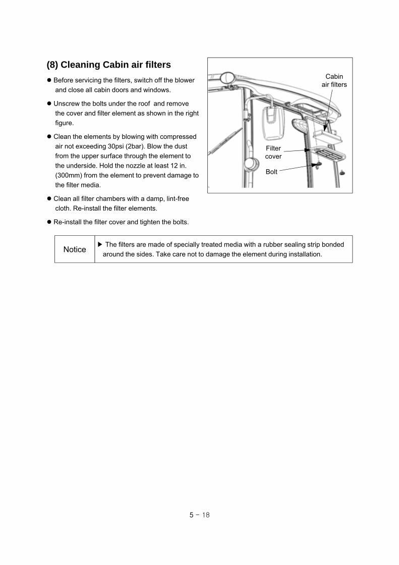
5 - 18
(8) Cleaning Cabin air filters
Before servicing the filters, switch off the blower
and close all cabin doors and windows.
Unscrew the bolts under the roof and remove
the cover and filter element as shown in the right
figure.
Clean the elements by blowing with compressed
air not exceeding 30psi (2bar). Blow the dust
from the upper surface through the element to
the underside. Hold the nozzle at least 12 in.
(300mm) from the element to prevent damage to
the filter media.
Clean all filter chambers with a damp, lint-free
cloth. Re-install the filter elements.
Re-install the filter cover and tighten the bolts.
▶ The filters are made of specially treated media with a rubber sealing strip bonded
around the sides. Take care not to damage the element during installation.Notice
Cabinair filters
Bolt
Filtercover
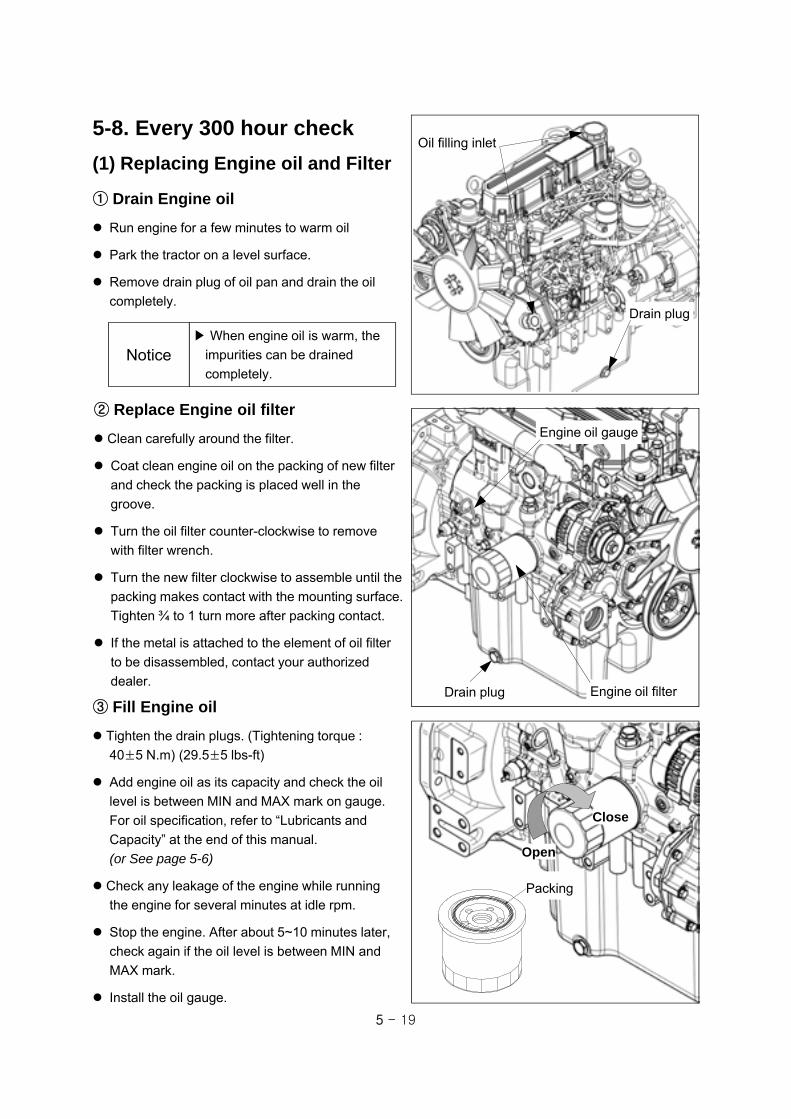
5 - 19
5-8. Every 300 hour check
(1) Replacing Engine oil and Filter
▶ When engine oil is warm, the
impurities can be drained
completely.Notice
① Drain Engine oil
Run engine for a few minutes to warm oil
Park the tractor on a level surface.
Remove drain plug of oil pan and drain the oil
completely.
③ Fill Engine oil
Tighten the drain plugs. (Tightening torque :
40±5 N.m) (29.5±5 lbs-ft)
Add engine oil as its capacity and check the oil
level is between MIN and MAX mark on gauge.
For oil specification, refer to “Lubricants and
Capacity” at the end of this manual.
(or See page 5-6)
Check any leakage of the engine while running
the engine for several minutes at idle rpm.
Stop the engine. After about 5~10 minutes later,
check again if the oil level is between MIN and
MAX mark.
Install the oil gauge.
② Replace Engine oil filter
Clean carefully around the filter.
Coat clean engine oil on the packing of new filter
and check the packing is placed well in the
groove.
Turn the oil filter counter-clockwise to remove
with filter wrench.
Turn the new filter clockwise to assemble until the
packing makes contact with the mounting surface.
Tighten ¾ to 1 turn more after packing contact.
If the metal is attached to the element of oil filter
to be disassembled, contact your authorized
dealer.
Engine oil gauge
Drain plug Engine oil filter
Close
Open
Packing
Drain plug
Oil filling inlet

5 - 20
▶ Be sure to stop the engine before loosening the oil filter.
▶ If the filter or oil is very hot, it may cause serious burns. After cooling down the
tractor sufficiently, replace the filters.
Warning
Hydraulicoil filter
Replace the HST filter according to the same
procedure of the hydraulic oil filter.
② HST filter
(2) Replacing Hydraulic Oil Filter
① Hydraulic oil filter (Main)
Park tractor on level surface and apply parking
brake and lower implements and stop the engine.
Carefully clean around the filter and set a clean
container under the filter.
Coat clean hydraulic oil on the packing of new
filter and check the packing is placed well in the
groove.
Turn the oil filter CCW to remove with filter wrench.
Turn the new filter CW to assemble until the packing makes contact with the mounting surface.
Tighten ¾ to 1 turn more after packing contact.
Run the engine at idle and check any leakage.
Check the oil level. If necessary, add new oil.
Open
Lock
HST filter
Close
Open

5 - 21
(3) Tension adjustment of Engine belt
Adjusting plateBolt
Generator pulley Water
pump pulley
Crank axle pulley
Check the tension of fan belt. If it’s not normal,
loosen the bolt and adjust the tension.
- Belt tension : crank shaft pulley ~ water pump
pulley
- Normal : approx. 10~12mm (0.4~0.5in.)
(if pressed by 98 N (22 lb))
When adjusting the tension,
1. loosen two locking bolts of alternator and bolt of
adjusting plate slightly
2. Tighten or loose the tension bolt to apply the
standard tension to the belt.
3. Tighten the locking bolts of alternator and
adjusting plate.
(4) Replacing Air cleaner element
(Dry type)
Remove the cover and pull the primary element
straight out, ensuring the safety filter element
remains in place.
Clean the inside of the air cleaner housing using
a clean damp cloth, taking care not to damage
the safety element.
Check if there is damage inside filter element by
using a light. If finding tiny crack or small holes
in the filter element or the gasket is damaged,
change it with a new one.
Insert the filter element by pushing it deeply into the filter housing.
Remove the dust of the evacuator valve and clean the inside of the cover.
Assemble the cover with the evacuator valve placed downward.
▶ Do not start the engine or close the hood if the filter element is not assembled..Notice
Cover Primary element
Evacuatorvalve
Safety filter element

5 - 22
(5) Toe-in
Check and adjust Toe-in of the front wheel as
follow.
Normal value ; B - A = 0~5 mm (0~0.2 in.)
Unscrew the lock nuts of the tie rod.
If you turn the tie rod clockwise at right hand side
“B-A” shall be increased.
After checking that Toe-in is correct, tighten the
lock nuts.
A
Lock nut
Lock nutFRONT
B
Tie rod
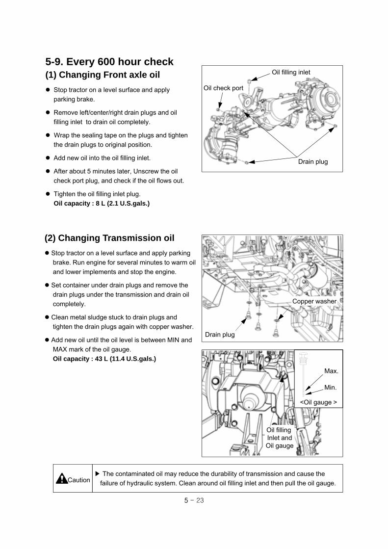
5 - 23
5-9. Every 600 hour check
Drain plug
Oil check port
Oil filling inlet (1) Changing Front axle oil
Stop tractor on a level surface and apply
parking brake.
Remove left/center/right drain plugs and oil
filling inlet to drain oil completely.
Wrap the sealing tape on the plugs and tighten
the drain plugs to original position.
Add new oil into the oil filling inlet.
After about 5 minutes later, Unscrew the oil
check port plug, and check if the oil flows out.
Tighten the oil filling inlet plug.
Oil capacity : 8 L (2.1 U.S.gals.)
(2) Changing Transmission oil
Stop tractor on a level surface and apply parking
brake. Run engine for several minutes to warm oil
and lower implements and stop the engine.
Set container under drain plugs and remove the
drain plugs under the transmission and drain oil
completely.
Clean metal sludge stuck to drain plugs and
tighten the drain plugs again with copper washer.
Add new oil until the oil level is between MIN and
MAX mark of the oil gauge.
Oil capacity : 43 L (11.4 U.S.gals.)
▶ The contaminated oil may reduce the durability of transmission and cause the
failure of hydraulic system. Clean around oil filling inlet and then pull the oil gauge.Caution
Drain plug
Copper washer
<Oil gauge >
Max.
Min.
Oil filling Inlet andOil gauge

5 - 24
(4) Adjusting Engine valve
clearance
Ask your authorized dealer to check the valve
clearance.
Normal : 0.25mm (0.0098 in)
If the gap is large, valves makes a loud tapping
noise and if the gap is too small, it is hard to
compress by which the engine output falls down
or burns a valve.
Valve clearance
1. Loosen the drain plug and drain the fuel inside
of the filter.
2. Disconnect electric wire of the fuel filter sensor.
3. Remove the element from the body
4. Remove the fuel filter sensor from the element and assemble it to the new element.
5. Attach the element to the body.
6. Connect electric wire of the fuel filter sensor.
7. Tighten the drain plug and bleed the air. (For further information, See page 5-26)
▶ Do not fill the new filter with fuel. The invisible fine foreign materials enter the
injection pump and it may cause damage to the fuel injection system.Caution
Drain plug
BodyElement
O-ring
Fuel filter sensor
(3) Replacing Fuel filter cartridge
(5) Checking Nozzle injection pressure
Contact your authorized dealer.
Normal injection pressure :
XR45 / XR45HST / XR50 / XR50HST : 14.7 MPa (2132psi)
XR60 : 11.8 MPa (1707psi)

5 - 25
(6) Replacing Cabin air filters
Before servicing the filters, switch off the blower
and close all cabin doors and windows.
Unscrew the bolts under the roof and remove
the cover and filter element as shown in the right
figure.
Clean both filter chambers with a damp, lint-free
cloth.
Replace the cabin air filters with a new one.
Re-install the filter cover and tighten the bolts.
▶ The filters are made of specially treated media with a rubber sealing strip bonded
around the sides. Take care not to damage the element during installation.Notice
Cabinair filters
Bolt
Filtercover

5 - 26
5-10. Every 2-year check(1) Replacement of Engine Coolant
① Capacity : 6.1 L ( 1.6 U.S.gals.)
② Check
Check the coolant of radiator and expansion tank
whether it is insufficient or not.
Do not open the radiator cap except to check the
coolant or change it.
Anti-freeze solution is filled up from the factory. After first winter, change the coolant to remove
foreign materials.
⑤ Anti-freeze
The amount of anti-freeze in the coolant must be determined on the ambient temperature. If the
amount of anti-freeze in the coolant is low, the coolant can be frozen and the engine and radiator
may be damaged.
Use anti-freeze solution always. if not, change the coolant with anti-freeze solution before winter time.
(Drain port : Radiator - drain cock, Engine - engine coolant drain plug)
Run the engine for 5 minutes after injecting the anti-freeze to mix it with water well.
Warning ▶When opening the radiator cap,
be careful of the escaping hot
water or steam.
▶Cool down the coolant
sufficiently before opening.
Drainage cock
③ Add coolant
Supply the clean soft water to the coolant. If not, the radiator shall be corroded or rust shall be
generated.
④ Replacing coolant
The drain cock must be loosened only when the
engine is cooled down.
Loosen the drain cock under the radiator to drain
the coolant in the engine and radiator.
Before supplying the coolant, wash out the
radiator with clean water 2~3 times.
Apply the overflow tube and supply the coolant up
to the inlet of radiator. Fill up the expansion tank
with coolant above the MIN. Change the coolant
with anti-freeze solution in cold weather.
Radiator cap

5 - 27
5-11. General maintenance (When required)
(1) Air-bleeding from Fuel system
The air in the fuel may cause weak injection or the failure of engine start or stop.
To prevent such failure, bleed the air from fuel system.
< Fuel system >
▶When changing fuel filter or fuel pre-filter, it is not needed to bleed the air from the
high pressure pipe.Notice
Fuel injection nozzle Fuel injection pipe
Fuel return pipe
Fuel injection pumpFuel filter
Fuel tank
1. Loosen the air bleed plug of fuel filter flange.
2. Apply a rag to the air bleed plug and press the
manual feed pump several times.
If no bubbles from the plug, the process
is completed.
3. Tighten the air bleed plug.
▶ If the foreign materials are stuck to the air bleed plug, it may prevent the air-
bleeding. In this case, unscrew the air bleed plug and remove foreign materials by
blowing.Notice
Air bleed plug
Manual feed pump
① Air-bleeding from Fuel filter

5 - 28
Air bleed bolt1. Turn key switch to ON position.
2. Loosen the air-bleed bolt by using a spanner and
turn it by hands until it stops.
3. If clean fuel without bubbles comes out, turn the
key switch to OFF position and tighten the air-bleed
bolt.
Tightening torque : 19.6~29.4 N.m(14.5~21.8 lb-ft)
▶ Cover the bleeding fuel with a rag so that it does not flow to other components.Notice
② Air-bleeding from Fuel injection pump
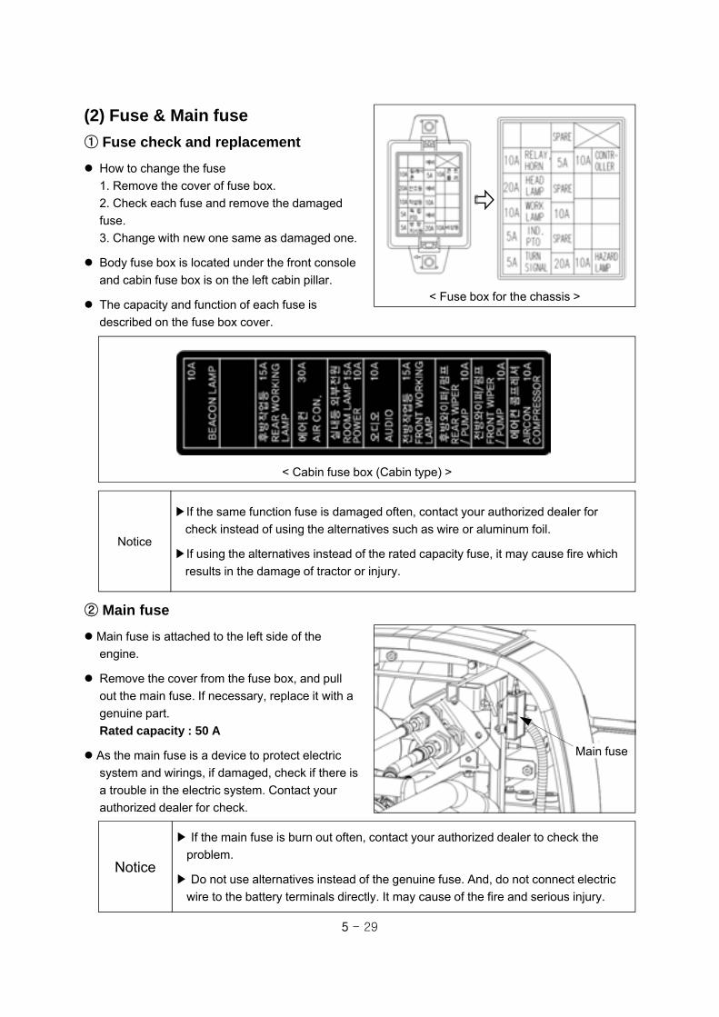
5 - 29
Main fuse
▶ If the main fuse is burn out often, contact your authorized dealer to check the
problem.
▶ Do not use alternatives instead of the genuine fuse. And, do not connect electric
wire to the battery terminals directly. It may cause of the fire and serious injury.
Notice
② Main fuse
Main fuse is attached to the left side of the
engine.
Remove the cover from the fuse box, and pull
out the main fuse. If necessary, replace it with a
genuine part.
Rated capacity : 50 A
As the main fuse is a device to protect electric
system and wirings, if damaged, check if there is
a trouble in the electric system. Contact your
authorized dealer for check.
▶If the same function fuse is damaged often, contact your authorized dealer for
check instead of using the alternatives such as wire or aluminum foil.
▶If using the alternatives instead of the rated capacity fuse, it may cause fire which
results in the damage of tractor or injury.
Notice
① Fuse check and replacement
How to change the fuse
1. Remove the cover of fuse box.
2. Check each fuse and remove the damaged
fuse.
3. Change with new one same as damaged one.
Body fuse box is located under the front console
and cabin fuse box is on the left cabin pillar.
The capacity and function of each fuse is
described on the fuse box cover.
< Cabin fuse box (Cabin type) >
(2) Fuse & Main fuse
< Fuse box for the chassis >
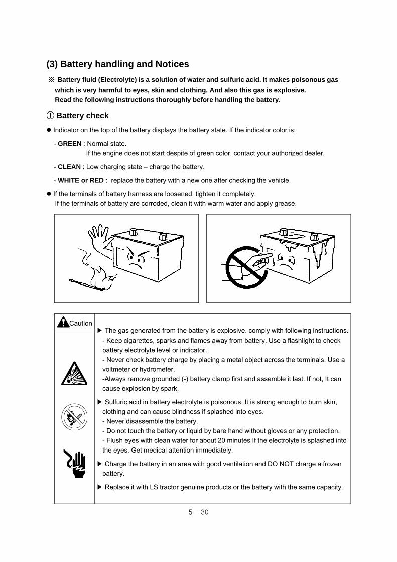
5 - 30
(3) Battery handling and Notices
※ Battery fluid (Electrolyte) is a solution of water and sulfuric acid. It makes poisonous gas
which is very harmful to eyes, skin and clothing. And also this gas is explosive.
Read the following instructions thoroughly before handling the battery.
① Battery check
Indicator on the top of the battery displays the battery state. If the indicator color is;
- GREEN : Normal state.
If the engine does not start despite of green color, contact your authorized dealer.
- CLEAN : Low charging state – charge the battery.
- WHITE or RED : replace the battery with a new one after checking the vehicle.
If the terminals of battery harness are loosened, tighten it completely.
If the terminals of battery are corroded, clean it with warm water and apply grease.
Caution▶ The gas generated from the battery is explosive. comply with following instructions.
- Keep cigarettes, sparks and flames away from battery. Use a flashlight to check
battery electrolyte level or indicator.
- Never check battery charge by placing a metal object across the terminals. Use a
voltmeter or hydrometer.
-Always remove grounded (-) battery clamp first and assemble it last. If not, It can
cause explosion by spark.
▶ Sulfuric acid in battery electrolyte is poisonous. It is strong enough to burn skin,
clothing and can cause blindness if splashed into eyes.
- Never disassemble the battery.
- Do not touch the battery or liquid by bare hand without gloves or any protection.
- Flush eyes with clean water for about 20 minutes If the electrolyte is splashed into
the eyes. Get medical attention immediately.
▶ Charge the battery in an area with good ventilation and DO NOT charge a frozen
battery.
▶ Replace it with LS tractor genuine products or the battery with the same capacity.

5 - 31
< When detaching >
< When attaching >
When detaching battery, remove the negative(-)
terminal from the battery first.
If not, when metal object is contacted between
positive(+) terminal and the body, it may cause
the dangerous spark.
When attaching the battery, the positive (+)
terminal must be attached first and the negative
(-) terminal must be connected last.
② Notices in attaching/detaching the battery
Caution ▶ Stop engine and apply parking brake and remove the ignition key before replacing
the battery.
▶ Put on eye protection and globes to protect human body from poisonous sulfuric
acid before handling the battery .
▶Always remove grounded (-) battery clamp first and assemble it last. If not, It can
cause an explosion by spark.
▶Keep all flames and sparks away and DO NOT smoke while you charge the battery.
▶Replaced old battery must be disposed of in a suitable manner, according to the
national legislation or local regulations. Contact your authorized dealer.
▶ Replace it with LS tractor genuine products or the battery with the same capacity.

5 - 32
< Do not charge the attached battery>
< when connecting the charger >
③ Notices in charging the battery using separate charger
As the battery fluid makes poisonous gas which can explode during the charging, comply with the
following instructions.
1. Detach battery from the tractor.
2. Wait until the battery is warmed to room
temperature.
3. Connect the cable of charger to the (+), (-) terminal
of the battery correctly.
- Connect (+) charger cable to (+) battery terminal.
: Red color
- Connect (–) charger cable to (–) battery terminal.
: Black color
4. Plug in charger cord.
5. Charge battery with a “SLOW CHARGE”.
6. Check the charging current and temperature of
electrolyte during the charging.
7. Unplug charge cord and remove charger cables.
8. Attach battery to the tractor.
▶Put on eye protection and globes to protect human body from poisonous sulfuric
acid before handling the battery .
▶Always remove grounded (-) battery clamp first and assemble it last. If not, It can
cause explosion by spark.
▶Keep all flames and sparks away and DO NOT smoke while you charge battery.
▶Detach battery from the tractor before charging. DO NOT charge directly while the
battery is attached to the tractor.
▶Turn off or unplug the charger cord, before connecting or disconnecting the charger
cable to or from the battery
▶Charge the battery in an area with good ventilation.
▶Do not charge the frozen battery.
▶Use the rated 12V-5A charger.
▶Never check battery charge by placing a metal object across the terminals.
Caution

5 - 33
ⓑ Removing Jumper cables
Remove jumper cables as right figure, “Removing
order of jumper cables”.
▶Pay attention not to change the (+) and (-) pole. If not, it may cause a failure of
electric circuit or the damage of wire and even the polarity of battery can be
changed at over-discharged state.Notice
< Removing order of jumper cables >
①②
③ ④ EngineNormal Discharge
Red cable
Black cable
Caution ▶ The gas generated from the battery can be exploded by spark.
DO NOT connect the negative(-) cable of auxiliary battery to the negative (-)
terminal of tractor battery. Make sure to connect to the engine block.
▶ Keep all flames and sparks away and DO NOT smoke while handling the battery.
④ How to use jumper cables
※ if the battery which is attached to the tractor is discharged and needs to connect a auxiliary battery,
follow the instructions as below.
< Connecting order of jumper cables >
①②
③ ④
EngineNormal Discharge
Red cable
Black cable
ⓐ Connecting Jumper cables
Check followings before connecting the cables.
- is the spring of clamp normal?
- Is the cable and clamp cut-off?
1. Stop engine, apply parking brake and remove the
ignition key.
2. Connect two (+) terminals of both batteries.
with red cable.
(tractor battery-①, auxiliary battery-②)
3. Connect one end of black cable to (-) terminal(③)
of auxiliary battery and the other end to engine
block desired to start (④).
4. Start engine. If the engine does not start,
check the electrolyte level of each battery.

5 - 34
5-12. Troubleshooting
Warning▶ To avoid injury due to sudden start, apply parking brake and place the
transmission gear in NEUTRAL position before checking and repairing.
System Faults Possible causes Solutions
Engine
The start motor does
not turn when turning
the key switch.
▲ Start safety switch is not
contacted.
▲ PTO switch is not on OFF
position.
▲ Discharge of battery
▲ Terminal loosened
▲ Key switch failure
▲ Start motor failure
▲ Depress the clutch pedal
fully
▲ Place PTO switch on OFF
position
▲ Charge or replace
▲ Tighten
▲ Repair or replace
▲ Repair or replace
The start motor turns
but the engine does
not start.
▲ The battery is weak
▲ bad ground
▲ Improper viscosity of engine
oil
▲ Air in fuel system
▲ Fuel filter clogged
▲ Error in engine body
▲ Fuel cock closed
▲ Charge or replace
▲ Tighten the ground
▲ Replace the oil with proper
viscosity.
▲ Bleed the air
▲ Wash or replace the filter
▲ Repair
▲ Open the cock
Engine revolution is
irregular.
▲ Air in fuel system
▲ Fuel filter clogged
▲ Injection nozzle clogged
▲ Fuel leakage
▲ Irregular fuel injection
▲ Bleed air
▲ Clean or replace the filter
▲ Repair or replace
▲ Repair
▲ Repair
Engine turns more
than maximum speed.▲ Impurities in governor ▲ Repair
Engine stops suddenly
during operation.
▲ Fuel shortage
▲ Fault of nozzle
▲ moving parts failure due to bad
lubrication
▲ Add fuel and bleed air.
▲ Repair or replace
▲ Repair
5 - 35
System Faults Possible causes Solutions
Engine
Engine stops at low
rpm.
▲ Fault of injection pump
▲ Valve gap is not correct
▲ Poor nozzle pressure
▲ Repair
▲ Adjust the gap
▲ Repair
Engine overheat
▲ Lack of engine coolant
▲ Bad fan belt tension or broken
▲ Dirt attached to the radiator
▲ Supplement
▲ Adjust belt tension or
replace
▲ Clean
The color of exhausted
smoke is white.
▲ Air cleaner clogged
▲ Engine oil exceeded
▲ Lack of fuel supply
▲ Wash element
▲ Adjust in proper level
▲ Repair
The color of exhausted
smoke is black.
▲ Bad quality of fuel
▲ Oversupply of fuel
▲ Fault of nozzle
▲ Use good quality fuel
▲ Repair
▲ Repair
Engine power is low.
▲ Injection nozzle clogged
▲ Carbon piled to valve seat
▲ Bad adjustment of valve gap
▲ Bad injection timing
▲ Lack of fuel supply
▲ Air cleaner clogged
▲ Repair
▲ Repair
▲ Repair
▲ Repair
▲ Check fuel system
▲ Clean or replace
Engine oil pressure
indicator is ON during
operation.
▲ Lack of engine oil
▲ Low viscosity of engine oil
▲ Warning light switch error
▲ Fault of oil pump
▲ Oil filter element is clogged
▲ Supplement
▲ Replace the proper oil
viscosity
▲ Replace
▲ Repair
▲ Replace element
Battery charging
indicator is ON during
operation
▲ Abnormal wiring
▲ Fault of alternator
▲ Fault of battery
▲ Bad fan belt tension or broken
▲ Check battery terminals and
ground, repair
▲ Repair or replace
▲ Replace
▲ Adjust belt tension or replace
Clutch
Clutch is slipped.▲ Wrong clutch pedal play
▲ Friction lining worn or broken
▲ Adjust
▲ Replace
Clutch does not cut-off.▲ Lining damaged
▲ Wrong clutch pedal play
▲ Repair or replace
▲ Adjust

5 - 36
System Faults Possible causes Solutions
Brake
Brake does not work or
only one side works.
▲ Wrong brake pedal play.
▲ Lining worn or broken
▲ Left/right pedal play is different
▲ Adjust
▲ Replace
▲ Adjust
After brake pedal
working, it does not
return.
▲ Return spring damaged
▲ Lack of grease in shaft parts
▲ Replace the spring
▲ Remove the rust, apply
grease
Hydraulic System
Lift arm does not raise.
▲ Lack of transmission oil
▲ Air in the suction pipe
▲ Hydraulic filter clogged
▲ Hydraulic pump failure
▲ Control valve failure
▲ Cylinder or cylinder related
parts broken
▲ Aid oil
▲ Tighten the filter or replace
seal of connecting parts
▲ Clean the filter or replace
▲ Repair or replace
▲ Repair or replace
▲ Repair or replace
Oil leakage
▲ Connecting part loosened
▲ Oil seal damaged
▲ Pipe cracked
▲ Tighten
▲ Replace
▲ Replace
If lever is placed on the
raising position, and
relief valve sound off.
▲ Upper limit of position control
lever is changed
▲ Adjust the upper limit
Lift arm does not lower
▲ Down speed control valve
locked
▲ Control valve failure
▲ Cylinder damaged
▲ Lift shaft turning part
damaged
▲ Turn the knob counter-
clockwise
▲ Repair or replace
▲ Replace
▲ Repair or replace

5 - 37
System Faults Possible causes Solutions
Steering System
Hydraulic steering
system does not work.
▲ Pump worn or part damaged
▲ Steering unit damaged or worn
▲ Oil leakage by steering
cylinder piston seal damaged or
worn
▲ Oil leakage by pipe damage
▲ Repair or replace
▲ Repair or replace
▲ Repair
▲ Repair or replace
Hard to operate the
steering wheel.
▲ Steering unit
- Steering unit spline and column
spline is not aligned
- Spool and sleeve damaged by
foreign material
- Excessive tightening torque of
end cap bolt
▲ Pump
- Low speed
- Wearing or failure
▲ Relief valve
- Valve spool clogged
- Setting pressure too low
▲
- Check mounted condition of
steering unit and column
- Replace
- Apply regular torque
▲
- Adjust RPM or Repair
- Repair or replace
▲
- Repair or replace
- Reset or adjust
Cylinder does not work
smoothly as steering
wheel movement
▲ Air in steering line if not used
for a long time
▲ Air in suction pipe
▲ Piston seal damaged
▲ Bleed air
▲ Repair
▲ Replace
Steering wheel turns to
the opposite direction.
▲ bad assembly of steering gear
▲ bad assembly of steering hose
▲ Repair
▲ Repair
Oil leakage of steering
pump, steering unit,
cylinder and fittings
▲ Seal damaged ▲ Replace seal
Abnormal noise
▲ Lack of oil
▲ Exceeding resistance of
suction line
▲ Air in system
▲ Aid oil
▲ Replace filter or repair
pump
▲ Bleed air

5 - 38
System Faults Possible causes Solutions
Electric System
Battery is not charge
▲ Abnormal wiring
▲ Alternator failure
▲ Lack of fan belt tension or
broken
▲ Abnormal battery
▲ Check the tightening state
of terminal and ground
▲ Repair or replace
▲ Adjust fan belt tension or
replace
▲ Replace
Headlight is dark.▲ Battery capacity is low
▲ Bad wiring and contact
▲ Charge or replace
▲ Check and repair
Headlight does not
ON.
▲ Light bulb cut-off
▲ Fuse blown
▲ Replace
▲ Check the cause, and
replace
Horn does not sound.
▲ Switch failure
▲ Abnormal wiring
▲ Horn failure
▲ Replace
▲ Repair
▲ Replace
Turn signal Light does
not work.
▲ Light bulb cut-off
▲ Bad connection
▲ Fuse blown
▲ Replace
▲ Tighten terminals
▲ Check the cause, and
replace it
Cold start aid indicator
does not ON. (option)
▲ Relay or timer damaged
▲ Bad connection of preheat
plug wiring
▲ Replace
▲ Check and tighten
Other illuminating and
indicator does not ON.
▲ Fuse blown
▲ Light bulb cut-off
▲ After removing the cause,
and replace
▲ Replace
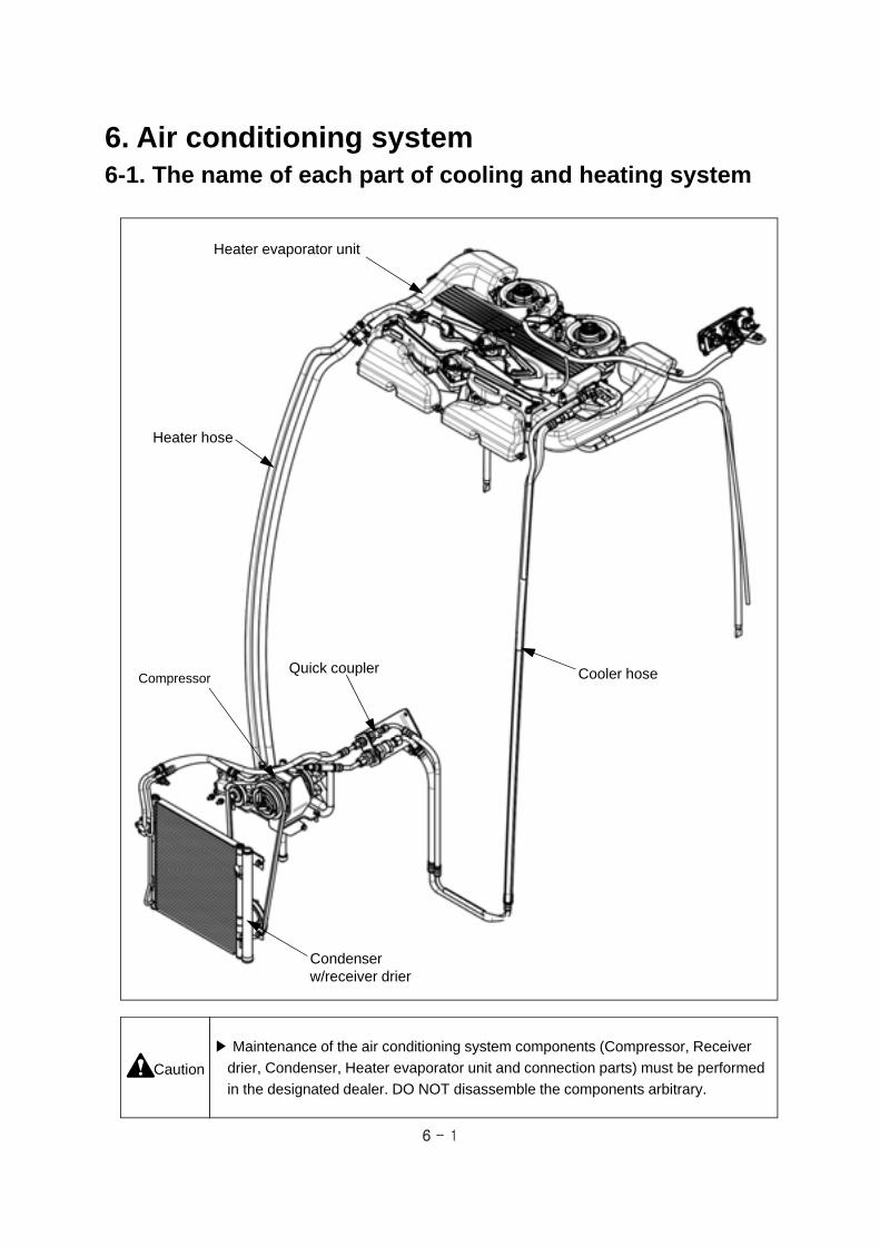
6 - 1
6. Air conditioning system6-1. The name of each part of cooling and heating system
Heater evaporator unit
Cooler hoseCompressor
Heater hose
Quick coupler
▶ Maintenance of the air conditioning system components (Compressor, Receiver
drier, Condenser, Heater evaporator unit and connection parts) must be performed
in the designated dealer. DO NOT disassemble the components arbitrary.Caution
Condenser w/receiver drier

6 - 2
Internal circulation inlet
6-2. How to use Air conditioner and Heater
Caution
Blower outlet
(1) How to operate air conditioner and heater
Air conditioner switch
- It is used to operate the air conditioner. If you press the switch button and turn the blower control
switch to Ⅰ,Ⅱ,Ⅲ or position, the operation lamp shall be ON and the air conditioner begins to
work.
Blower control switch
- Blower is controlled by 4 stages. If blower control switch is on “O”, air conditioner does not work.
Heater control switch
- It is used for selecting warm or cool air. Turn the switch clockwise (blue) for cool air, and otherwise,
turn it counter-clockwise (red).
Air-conditionerswitch
Blower controlswitch
Heater controlswitch
Direction controlswitch
(2) Air direction control
To control the air direction, adjust the blade angle of the blower outlets.
For internal circulation, move the ventilation lever to the internal circulation position.
When operating the air conditioner or heater, open the blower outlets always.
▶Never sleep in the cabin during the air conditioner or heater running.
It may cause suffocation.
▶When operating in the cabin for a long time, ventilate air from the outside
occasionally.
Ventilation lever
External circulation
Internal circulation

6 - 3
6-3. Every 6 month check
(1) Checking refrigerant amount
Check the refrigerant amount periodically. Have to contact your authorized dealer for it.
Refrigerant : R-134a, 850 ~ 900 g (29.98 ~ 31.74 oz)
The components of the air conditioning system have to be handled by authorized service expert.
(2) Cleaning Condenser and Radiator screen
Stop engine and allow engine to cool. Open bonnet and remove the radiator screen.
Wash the mud or foreign materials added to the condenser and radiator screen with soft brush or low
pressurized air or water.
Pay attention that the cooling fin does not damaged. If necessary, repair the distortion of fin.
(4) Belt tension adjustment
Check the belt tension is proper and If necessary,
adjust the tension by compressor adjusting bolt.
Tension : Approx. 10 mm (0.4 in.)
(when pressed by 50N (11.2 lb.f))
Check the damaged part of the belt and if
necessary, after checking the pulley alignment,
replace it by a new one.
(3) Checking Leakage
Check the tightening torque and oil leakage state
of the connecting section.
If oil spot and foreign materials are stuck to the
air conditioner components or line, it means that
there is leakage of refrigerant on that point.
Contact your authorized dealer for check.
Adjusting bolt
Quickcoupler
Belt
Check point
Air-conhose
Compressor
Compressor

6 - 4
6-4. Every year check(1) Compressor check
Check the oil leakage on the magnet clutch in front of the compressor.
Check the abnormal noise sounds and If necessary, contact your authorized dealer for check.
(2) Control switch check
Check the electric switches of the control panel is normally operated.
▶If there is a trouble on air conditioning system, DO NOT disassemble the
components arbitrary, contact your authorized dealer for check.Caution
6 - 5
6-5. Troubleshooting
No. Failures Cause Actions
1 Fan motor does not turn. Fuse blown Check and replace.
Wiring cut off and poor
connection.
Repair the wiring or
connect right.
Failure of fan motor. Replace.
Resistor, relay and switch
cut off.
Replace.
2 Fan motor is normal but the air
volume is small.
Evaporator or heater core
was clogged.
Remove the obstacles
and clean the cores.
Duct was misaligned. Repair the duct.
Fan damaged or Fan motor
failure.
Replace.
Filter was clogged Clean or replace
3 Air
conditioning
is insufficient
despite of
the normal
operation of
compressor
and blower.
Low and high
pressure is low.
Leakage of refrigerant. Contact the dealer.
Low and high
pressure is high.
Refrigerant overcharged. Contact the dealer.
Condenser or radiator screen was clogged.
Clean condenser and
the screen.
Air is in air conditioning line. Contact the dealer.
Expansion valve does not
control the refrigerant flow.
Contact the dealer.
Low pressure is
high, high
pressure is low.
Compressor leakage. Contact the dealer.
Low pressure is
vacuum
intermittently.
Water is in air conditioning
line.
Contact the dealer.
Low pressure is
vacuum, high
pressure is low.
Receiver dryer, pipe or expansion valve is clogged.
Contact the dealer.

6 - 6
No. Failures Cause Actions
4 The compressor does not turn or it is hard to revolve.
Belt loosened. Adjust the belt tension.
Temperature switch or
pressure switch is “ON”.
Check refrigerant
amount.
Coil of magnet clutch was
shorted or cut off.
Contact the dealer.
Compressor failure. Contact the dealer.
Wiring cut off or poor connection such as ground.
Check and repair.
5 The warm airflow does not blow. The amount of warm water is small.
Check and add the
engine coolant.
Heater line is clogged or
distorted.
Check and repair.
Poor operation of the
thermostat of engine
coolant.
Repair or replace.

6 - 7
6-6. System diagram
Heater evaporator
Fan motor
Evaporator core
Heater core
Hot
wat
er
Control panel
Engine
Compressor
Fan
Radiator
Condenser
Quick coupler
Receiver dryer
Heater lose
Cooler hose
Line
Expansion valve

7 - 1
7. Dimension and Specification
(Unit : mm)① Cabin model

7 - 2
XR45 / XR45HST XR50 / XR50HST XR60
WE
IGH
T
Mechanical Type 1910kg (4211 lb) 1910kg (4211 lb) 1925kg (4244 lb)
HST Type 1890kg (4167 lb) 1890kg (4167 lb) N/A
Bumper 21kg (46.3 lb) (optional)
Front weight 20kg (44.1 lb) x 4 (optional)
EN
GIN
E
Model S4Q-L31.6kW S4Q-L34.6kW S4QT(60ps)
Type 4-stroke, vertical, water cooling
No. of cylinder 4
Diameter x stroke 88 x 103mm (3.46 x 4.05 in)
Displacement 2505cc (152.86in3)
Compression ratio 22 : 1
Engine speed 830 ~ 2750 rpm 830 ~ 2780 rpm
Maximum torque 140N.m / 1500 rev/min 140N.m / 1500 rev/min 170N.m / 1500 rev/min
Rated power 32.0kW / 2600 rev/min 35.0kW / 2600 rev/min 41.6kW / 2600 rev/min
FU
EL
INJE
CT
ION
SY
ST
EM
Type Bosch VE Type
Fuel filter Replaceable cartridge type
Injection order 1-3-4-2LU
BR
ICA
TIO
N
SY
ST
EM
Type Forced circulation
Pump Trochoid gear pump
Filter Replaceable cartridge type
CO
OLIN
G
SY
ST
EM
Pump Centrifugal type
Temperature control Thermostat
Air cleaner Dry
TR
AN
SM
ISS
ION
Type 16x16 Mechanical / 32x16 Mechanical with creeper (optional) / HST
Main clutch Dry single clutch for Mechanical only
Forward / Reverse Synchro-shuttle type for Mechanical / HST pedals
Differential lock Mechanical pedal type

7 - 3
XR45 / XR45HST XR50 / XR50HST XR60
PT
O
Type Independent PTO with wet disk clutch / GSP (optional)
No. of speed 3 speed gears (optional)
PTO / Engine
1st speed : 540 rpm / 2409 rpm
2nd speed : 750 rpm / 2375 rpm
3rd speed : 1000 rpm / 2381 rpm
HY
DR
AU
LIC LIF
T
3-Point linkage CAT.1
Draft load detection Upper link (optional)
Lowering speed control and cylinder
fixing deviceDown speed control valve
Pump Gear pump type, Engine drive
Rated flow 31.2LPM (8.2GPM)
System pressure 17MPa (2466psi)
Lift capacity
Lower link end
1245 kgf (2745 lbf)
24” behind lift point
1075 kgf (2370 lbf)
RE
MO
TE
C
ON
TR
OL
Type Double acting (Spring return type / Detent type(optional))
No. of Q/coupler 4EA (optional : 2 or 6EA)
F/Loader coupler Front outlet valve / Joystick loader valve (optional)
ST
EE
RIN
G S
YS
TE
M
Type Hydrostatic
Oil Transmission oil
Min. turning radius (with brake)
2.74m (8.99 ft)
Max. steering angle 57° / 45°
No. of steering turns 2.8 turns (lock to lock)
Oil flow 15.6LPM (4.1GPM)
System pressure 14.0MPa (2031.psi)

7 - 4
XR45 / XR45HST XR50 / XR50HST XR60
ALT
ER
NA
TO
R
Rated output 12V-50A
Voltage control Built-in (IC type)
BA
TT
ER
Y
Voltage 12V
Capacity 80AH
ST
AR
T
MO
TO
R
Output power 12V-2.0kW
Operation Solenoid
LIGH
TS
Headlights(Lower / Upper)
12V 55W / 60W
Turn signal lights 12V 21W
Side lights (front) 12V 5W
Stop light / Taillight (rear)
12V 21W / 5W
Work lights 12V 27W (Grille) / 37.5W (Cab)
Instrument lights LED
Indoor light (CAB) 12V 10W
Instrument indicator lights
LED
Cold start aid Glow plugS
TD
. AG
RI.
TIR
E
Front 8.3-20 (6PR)
Rear 12.4-28 (6PR)
WH
EE
L TR
AC
K
AD
JUS
TM
EN
T
Front
Tracks 5
Dimension 1244 ~1444 mm (49.0 ~ 56.9 in.)
Rear
Tracks 4
Dimension 1140 ~ 1306 mm (44.9 ~ 51.4 in.)
** These specifications are only general product information and can be changed to improve the product qualification without any prior notification **
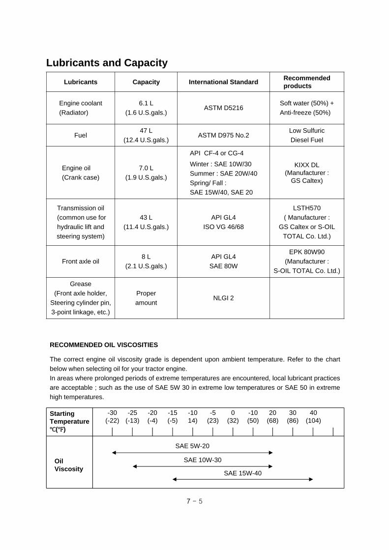
7 - 5
Lubricants and Capacity
Lubricants Capacity International StandardRecommended products
Engine coolant
(Radiator)
6.1 L
(1.6 U.S.gals.)ASTM D5216
Soft water (50%) +
Anti-freeze (50%)
Fuel47 L
(12.4 U.S.gals.)ASTM D975 No.2
Low Sulfuric
Diesel Fuel
Engine oil
(Crank case)
7.0 L
(1.9 U.S.gals.)
API CF-4 or CG-4
Winter : SAE 10W/30
Summer : SAE 20W/40
Spring/ Fall :
SAE 15W/40, SAE 20
KIXX DL(Manufacturer :
GS Caltex)
Transmission oil
(common use for
hydraulic lift and
steering system)
43 L
(11.4 U.S.gals.)
API GL4
ISO VG 46/68
LSTH570
( Manufacturer :
GS Caltex or S-OIL
TOTAL Co. Ltd.)
Front axle oil8 L
(2.1 U.S.gals.)
API GL4
SAE 80W
EPK 80W90
(Manufacturer :
S-OIL TOTAL Co. Ltd.)
Grease
(Front axle holder,
Steering cylinder pin,
3-point linkage, etc.)
Proper
amountNLGI 2
RECOMMENDED OIL VISCOSITIES
The correct engine oil viscosity grade is dependent upon ambient temperature. Refer to the chart
below when selecting oil for your tractor engine.
In areas where prolonged periods of extreme temperatures are encountered, local lubricant practices
are acceptable ; such as the use of SAE 5W 30 in extreme low temperatures or SAE 50 in extreme
high temperatures.
StartingTemperature
( )
OilViscosity
-30(-22)
-25(-13)
-20(-4)
-15(-5)
-1014)
-5(23)
0(32)
-10(50)
20(68)
30(86)
40(104)
SAE 10W-30
SAE 15W-40
SAE 5W-20

LS T
RA
CT
OR
OPE
RA
TO
R‘S
MA
NU
AL
LS TRACTOR
OPERATOR'S MANUAL
XR
-SE
RIE
S
XR45 XR45HST XR50 XR50HST XR60
P/NO 52113201DATE 20130000
GML Sport AB bildades 1994 och utvecklades snabbt till att bli en av landets ledande leverantörer av maskinutrustning för skötsel av gröna sportytor. Företaget har alltid satt en stolthet i att agera både som kunskapsförmedlare och samarbetspartner till användarna.
På senare år har en ny marknad för olika typer av tjänster inom drift, renovering och anläggning av gröna sportytor till golf- och idrottsplaner börjat växa fram. Inom just dessa områden, entreprenad, har GML Sport genom offensiva satsningar snabbt tagit en ledande position. Företaget befinner sig i en stark expansion på tjänstesidan och räknar med att antalet uppdrag och medarbetare kommer att öka kraftigt under de kommande åren.
GML Sport är en komplett leverantör av professionella lösningar för alla idrotter som utövas på gröna sportytor – både när det gäller tjänster och maskiner. Inget annat företag i landet kan matcha den kunskap och erfarenhet inom Sports Turf Management som du möter hos GML Sport.
I vårt dagliga arbete utgår vi från filialer i de tre storstadsområdena men åtar oss naturligtvis uppdrag över hela landet.
GML Sport AB är certifierade enligt båda kvalitet ISO 9001 och miljö 14001.
Kontakta oss – vi har lösningen för dig!
Om GML Sport
GML SPOrT ABGarvaren, SE-341 60 Ljungby
+46 (0)372-885 00 | [email protected] www.gmlsport.se