ls-dyna data management using visual … data management using visual-environment ......
TRANSCRIPT

6th European LS-DYNA Users’ Conference
1.1.2 1.41
LS-DYNA Data Management using Visual-Environment
Authors: Shivakumara H Shetty, Velayudham Ganesan, Suthy C Sivalingam,
Etienne De Pommery, Jean Louis Duval ESI Group
Correspondence: ESI Group
36800 Woodward Avenue, Suite 200 Bloomfield Hills, MI 48304
USA Ph: (248) 203-0642
Email: [email protected] URL: www.esi-group.com
Abstract:
Realistic Simulation is considered to be the most important part of Simulation Based Design (SBD) in the product development cycle. Realistic simulations can not be achieved just by using currently available CAE pre and post processing functionalities alone. Many of the complex requirements of CAE modeling need to be addressed by having a synchronized CAD and CAE environment. CAE analysts need a tool, which will allow them to control variables, manage data, adapt the changes, and transport across different disciplines of analysis such as Crash, Safety, NVH and Durability. ESI’s Open VTOS™ application called “Visual-Environment (VE)” provides such capabilities as a complete solution to SBD. VE is an integrated suite of pre-post, CAE data management tools synchronizing CAD and CAE. It also provides several contexts based on individual FE solvers. Visual-Crash DYNA (VCD) is for LS-DYNA model setup, Visual-Composer (VCO) is for model assembling and data management by linking CAD (Geometry) and FE (Physics). VCO and VCD allow managing LS-DYNA model data linking to corresponding CAD assemblies. It helps to adapt fast design changes, communicate the engineering changes back to design, and to track the models and solutions of multiple iterations. Visual-Safe is an advanced pre-processor for safety features, Visual-Mesh a general purpose meshing tool, Visual-Viewer (VVI)-a general purpose plotting and simulation application, Visual-Life Nastran (VLN) a general purpose pre processor for NASTRAN, Visual-Process Executive-an application for process customization and automation are the other contexts to name a few.

6th European LS-DYNA Users’ Conference
1.42 1.1.2
This paper describes the LS-DYNA data management functionalities of Visual-Environment in Crash and Safety simulation with productivity examples and process automation.
Keywords: Simulation Based Design, Open VTOS, Visual-Environment, Visual-Crash DYNA,
Visual-Composer, Visual-Process, Visual-Viewer, Visual-Mesh, Visual-Safe
Introduction A simulation based design is achievable by increasing the number of simulations to make better engineering decision, which will help to achieve better design with less number of prototypes. The conventional approach of managing the LS-DYNA data takes lot of time and effort to build each iteration models for each load cases (Front Impact, Side Impact, Rear Impact, etc.). Productivity improvement can be achieved if there is an automated approach to track design and engineering changes of iterations and adapt them into a work flow. A tool which can bring both CAD and CAE together and help to monitor the different types of data flow between CAD and CAE is essential to achieve this. ESI’s Visual-Environment (VE) is the tool which provides an environment where CAD and CAE can be bridged to propagate the design and engineering data across domains. Visual-Environment has been built by merging ESI Group’s Open VTOS solution into EASi’s VISTA1 technology. The embedded VISTA data model offers a versatile environment where new applications and interfaces can easily be implemented. VE is supported in all OS platforms including native windows, Unix, Linux and 64-bit version. It is a context based environment for different domain needs such as Visual-Crash Dyna (VCD) for LS-DYNA, Visual-Life Nastran (VLN) for NASTRAN, Visual-Mesh (VME) for meshing and model assembling, Visual-Viewer (VVI) for post processing, Visual-Safe (VSA) for advanced safety applications, Visual-Process (VPR) for CAE process automation, Visual-Composer (VCO) for model assembly and load cases iteration data management and so on. All the contexts are integrated seamlessly to facilitate the user to navigate within one environment for multiple solver domains.
Visual-Environment Contexts As mentioned above, VE has several contexts out of which a few are explained below from the LS-DYNA users point of view. All the dialogs are easily scriptable through Python language for quick customization.

6th European LS-DYNA Users’ Conference
1.1.2 1.43
Visual-Mesh Visual-Mesh is a complete meshing tool, which supports CAD Import, 2D and 3D Meshing and editing features. It also provides batch-meshing utility based on topology meshing with user guidance as well as automatic approach.
Visual-Crash Dyna Visual-Crash Dyna (VCD) is the enhanced version of EASi-CRASH DYNA inheriting all other standard features of VE that makes VCD to be highly productive tool. It provides users with fast iteration and rapid model revision process, from data input to visualization for crashworthiness simulation and design. This environment provides quick model browsing, advanced mesh editing capabilities and rapid graphical assembly of system models. VCD allows graphical creation, modification and deletion of contacts, materials, constraints, control cards and all crash entities. In VCD, model validation tools helps in correcting errors and improve the model before submitting it to a solver, thus saving time and resources.
Visual-Viewer Visual-Viewer is the advanced Post-Processing tool with state-of-the-art Plotting/Viewing utility. This caters to the requirements of the CAE community. Viewer is built on the multi page/multi plot environment, which enables the user to group data into pages and plots. Viewer is designed with intuitive and sleek user interface as windows-look-and-feel. Complete plotting session is captured and it can be re-executed without losing any data. It is also fully command-driven that enables the user to execute at command-line.
Visual-Process Visual-Process is an advanced CAE environment for process customization and automation. The process templates establish high productivity and standardization by customizing any regulatory CAE procedure such as FMVSS, ECE etc and corporate best practices. The environment’s state of the art process execution methodology allows carrying out the model building automatically and semi automatically for consistent results. The process templates for FMVSS201, Pedestrian head impact target identification are to name a few which are available in Visual-Process Executive context.
Visual-Composer Visual-composer is an advanced model assembly management tool for PDM systems. It bridges CAD and CAE data. It allows users to share and re-use the single load case model to create various iteration models for different disciplines (crash, safety, NVH…). It is a database enabled tool containing an integrated “Simulation Content Manager (SCM)” for work flow, user roles and model data management.

6th European LS-DYNA Users’ Conference
1.44 1.1.2
LS-DYNA CAE Life Cycle Management
Visual-Environment provides integrated tools and functionalities to manage the LS-DYNA data through out the product life cycle of any CAE programs. The phases of the data management are
1. Geometry Data Management 2. LS-DYNA Model Data Management 3. Results Data Management 4. CAE Best Practice Management (Process Automation) 5. Enterprise Engineering Data Management
Geometry Data Management Any LS-DYNA simulation starts with finite element mesh generation form CAD model. Visual-Mesh context (Fig. 1) in VE provides tools to create and edit geometries (1D, 2D and 3D). Following geometric data management activities can be carried out in VME. Some of the productivity features of VME are as follows.
a. Automatic Geometry cleanup b. Auto Mesh c. Batch mesh process
Fig. 1: Visual-Mesh Context in Visual-Environment
6th European LS-DYNA Users’ Conference
1.1.2 1.45
LS-DYNA Model Data Management Some of the productive features of model data managements are
1) Sub-Assembly Replace 2) Advanced Part Replace 3) Model Assembler 4) Weld Tools 5) Integrated Environment for Basic and Extended Coupling 6) Automatic Seatbelt Routing and Dummy Positioning
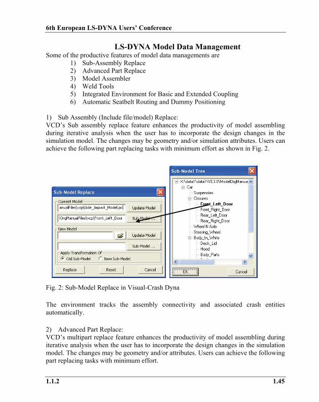
1) Sub Assembly (Include file/model) Replace: VCD’s Sub assembly replace feature enhances the productivity of model assembling during iterative analysis when the user has to incorporate the design changes in the simulation model. The changes may be geometry and/or simulation attributes. Users can achieve the following part replacing tasks with minimum effort as shown in Fig. 2.
Fig. 2: Sub-Model Replace in Visual-Crash Dyna The environment tracks the assembly connectivity and associated crash entities automatically. 2) Advanced Part Replace: VCD’s multipart replace feature enhances the productivity of model assembling during iterative analysis when the user has to incorporate the design changes in the simulation model. The changes may be geometry and/or attributes. Users can achieve the following part replacing tasks with minimum effort.

6th European LS-DYNA Users’ Conference
1.46 1.1.2
• Replace single part by multiple parts • Multiple parts by single part • Multiple parts by multiple parts.
The environment tracks the part connectivity and associated crash entities automatically. 3) Model Assembler: Organizing the data easily, quickly and efficiently:
• Retaining include files without merging all data into one single model has become simple task in VCD.
• Creating, modifying, deleting and viewing of include files as sub-models and main model is available in the interface.
• Identification and automatic grouping of connections – both within and between sub-models (include files)
• Ability to locate any entity and identify the appropriate sub-model • Ability to work with and export only selected sub-models as include files as
shown in Fig. 3.
Fig. 3: Model Organization in Visual-Crash Dyna 4) Weld Tools: Advanced options for weld creation and modification: There are several weld utilities available for LS-DYNA mesh independent and node-node weld elements creation and modification. An intuitive interface is also available which can be invoked instantly for viewing, validating the weld points and weld

6th European LS-DYNA Users’ Conference
1.1.2 1.47
elements associated with the FE model. One of the most valuable features is the weld comparison tool to compare master weld file and/or mesh independent welds between two different models. The feature identifies and displays the difference between two different models. The user can view the matching and/or un-matching welds, delete or copy the welds from one model to another as shown in Fig. 4. Fig. 4: Advanced weld Functionalities in Visual-Crash Dyna 5) LS-DYNA/ Madymo Coupling: A unique feature of coupling Madymo rigid body models with LS-DYNA FE models is available with ease-of-use interface. VCD automatically takes care of creating the necessary coupling cards in LS-DYNA and Madymo models accordingly. ESI’s VISTA data model enables both the LS-DYNA and Madymo data in single environment (only software for coupling interface available in industry now is EASi-CRASH DYNA2) to import and export without loosing associated coupling cards3,4. Coupling for latest version of LSDYNA 971-Madymo 6.3 is available.
Results Data Management Some of the productive features of LS-DYNA results data managements are
• Integrated post processing environment for animation, visualization, contour plots, XY plots, and reports.

6th European LS-DYNA Users’ Conference
1.48 1.1.2
• Overlay and Synchronize AVI, Simulation, test results and Plot. • Viewer supports complete session and command Driven Environment. • Instant plotting of iterations using “CHASE IT”erations. Works for both test
and CAE data. • Intelligent sorting and Global control on data as well as template support are
available in Viewer. • Post processing templates can be quickly generated and deployed. • Intuitive object oriented Python scripting interface is made available to
manipulate the post processing data as shown in Fig. 5.
Fig. 5: Advanced Post Processing Functionalities in Visual-Viewer
CAE Best Practice Management (Process Automation) Visual-Process context in the VE environment enables the users seamlessly switch to Process Automation interface. In this interface, customized process templates are available to execute for particular modeling task automatically or semi-automatically. Most commonly used regulatory test simulations such as FMVSS IIHS, etc are captured and automated in this environment.

6th European LS-DYNA Users’ Conference
1.1.2 1.49
Fig. 6: Visual-Process and Process Templates of regulatory test procedures Fig.6 shows Visual-Process interface and a few process templates of standard regulations. There are several other process templates which help to achieve high productivity, especially, these process templates allows to create more models and more iterations in order to achieve better decision towards simulation based design. VE also provides a Software development environment (Visual-SDK) for the users to create and modify the process template. This helps additional flexibility to capture best modelling practice and build a process template to achieve the automation of repetitive and standardized task flow.
Enterprise Engineering Data Management (Visual-
Composer) VE provides CAE data management tool called Visual-Composer, which in turn contains a data manager called “Simulation Content Manager (SCM)”. It is connected to a vault of data using IBM DB2 (or could be any other data bases such as Team Center or File Based system). SCM contains the CAD assembly, corresponding CAE data, simulation attributes of each component of assembly and other attributes (user information, simulation progress, CAD details such as component, gage, material, connections and PDM attributes). The CAE details can have multiple FE mesh representations for different domain applications with FE attributes such as mesh size, intended use of mesh, connection format etc for each component. Thus SCM provides complete data management for CAE including tracking the simulation data. Starting with a Master Assembly which is a replica of the Bill of Material from PDM, Visual-Composer is a front end as a model assembly management tool. It helps to create

6th European LS-DYNA Users’ Conference
1.50 1.1.2
necessary load cases for group of CAE users depending on corporate requirement. SCM allows to assign user/group roles namely Project Manager, Team Manger, Project Engineer etc, to achieving restricted access to the program data.. A typical CAE work flow diagram using Visual-Composer is shown in Fig. 7.
Fig. 7: Visual-Composer Workflow The representation of Master Assembly, Load Cases and Iteration Models are shown in Fig. 8. The load cases can be created as sub model assembly for any type of solver. For example, if a crash model for frontal in LS-DYNA has to be assigned to a particular user group, a load case assembly for frontal crash can be filtered from the master assembly in Visual-Composer interface. Using SCM, the load case assembly can be given privileges to the particular user group. The user group can then query and filter CAE data by giving necessary simulation conditions such as element size, part thickness and create several iteration models. The interface also allows cloning any iteration model for consecutive iterations to reduce modeling time. If any new design change arrives, the tool can trigger an alert till iteration model propagating the changes from PDM to CAE. A quick update of the iteration model for new design changes can be done in the interface by just one click which saves a lot of re-work on the load case or iteration models. In the similar way, the CAE users can propagate the engineering recommendation or changes which are from iteration models to Master Assembly.
PDM
Links
Visual-Composer
Mesh Visual-Mesh/Other
S O L V E R
Reports
Quality check processes
Crash
CFD
NVH
Safety
Simulation Content Manager (SCM)
VA
Load Cases for Different Domains
Iteration1 Iteration2 Iteration3
Iteration1 Iteration2 Iteration3
Iteration Models for each Load Case

6th European LS-DYNA Users’ Conference
1.1.2 1.51
Fig. 8: Master Assembly, Load Case and Iteration Model representation in Visual-Composer A schematic view of the design change propagation and engineering change propagation is shown on the Visual-Composer workflow diagram in Fig. 9.
PDM
Links
Visual-Composer
Mesh Visual-Mesh/Other
S O L V E R
Reports
Quality check processes
Crash
CFD
NVH
Safety
Simulation Content Manager (SCM)
VA
Load Cases for Different Domains
Iteration1Iteration2 Iteration3 …
Iteration1Iteration2 Iteration3 …
Iteration Models for each Load Case
Design Change
Engg. Change
Master Assembly Load Cases
Iteration Models
Iteration Models
6th European LS-DYNA Users’ Conference
1.52 1.1.2
Fig. 9: Propagation of Design and Engineering Change Throughout the work flow, the SCM captures the data tracking and allows monitoring the data flow, system efficiency, fast reporting and CAE communication across the domains. For example, a crash model which passed crash worthiness simulation can directly be supplied for NVH or Safety or Durability study and the mutual data access by respective CAE user is tracked accordingly by the user privileges. Hence Visual-Composer and SCM together plays as CAE data management tool having the following salient features
• Database enabled (with security protocols like https, ftps, single sign on using LDAP etc)
• Import of assembly structure from CAD data base (e.g: CATIA, UG master assembly information of CAD parts and their metadata like gage, material etc)
• Bridges CAD and FE models (VE’s single data model stores CAD information and physics of different solvers including LS-DYNA entities)
• Capability to create models for different domains like crash, safe, NVH etc from one single master model
• Re-use of the FE model for different discipline (e.g: one FE model for frontal crash and NVH load case set up)
• Simultaneous creation of iteration models by different users (depending on privileges)
• Store data and track modeling process, system efficiency, communication among different domains
• Update of new component (CAD, FE) instantly without re creating the models • Capability to integrate 3rd party tool (meshing tools, launching solver
submission scripts, queuing tools etc) • User management and privileges assignment
Summary and Conclusions OEMs and suppliers have substantial potential for improving the productivity by synchronized CAD and CAE environment. This paper has presented what this potential is, highlighted how the productivity improvements can be achieved in ESI’s Visual-Environment, and mentioned the CAE automation capabilities within VE for potential time saving. Further improvements in productivity can be achieved with combination of process automation technology with optimisation and robust system design techniques.

6th European LS-DYNA Users’ Conference
1.1.2 1.53
References
1. Velayudham Ganesan, David Piesko, Jean-Louis Duval, “Fast NEW METHODOLOGY FOR Regulatory test simulation” Proceedings from The 8th International LS-DYNA Users Conference, 2004.
2. Shivakumara Shetty, Petter Sahlin, “Productivity Gain in Crashworthiness
Simulation EASi-CRASH for Complete Safety and Crash Modeling for LS-DYNA”, Proceedings from the 5th Euoprean LS-DYNA users Conference, 2005.
3. Shivakumara H Shetty, Velayudham Ganesan, “Productive Environment for Quick
CAE Modeling and Simulation-Visual Environment”, proceeding from 9th International LS-DYNA users conference, 2006.
4. LS-DYNA 971 User Manual, LSTC, USA. 5. MADYMO 6.3 User Manual, TNO, Netherlands.

6th European LS-DYNA Users’ Conference
1.54 1.1.2