lp pyra 10 - ghm group · - 1 - lp pyra 10 1 introduction the pyranometer lp pyra 10 measures the...
TRANSCRIPT
- 1 -
LP PYRA 10
1 Introduction
The pyranometer LP PYRA 10 measures the irradiance on a flat surface (Watt/m2). The radiation measured is the sum of direct solar irradiance and diffuse irradiance (global radiation). The LP PYRA 10 is a pyranometer classified as “Secondary Standard” in accordance with ISO 9060 and according to the publication "Guide to Meteorological Instru-ments and Methods of Observation”, fifth edition (1983) of WMO. The pyranometer is available in four versions: LP PYRA 10 PASSIVE* LP PYRA 10 AC ACTIVE with 4..20 mA CURRENT output LP PYRA 10 AV ACTIVE with 0..1 Vdc, 0..5 Vdc, 0..10 Vdc VOLTAGE out-
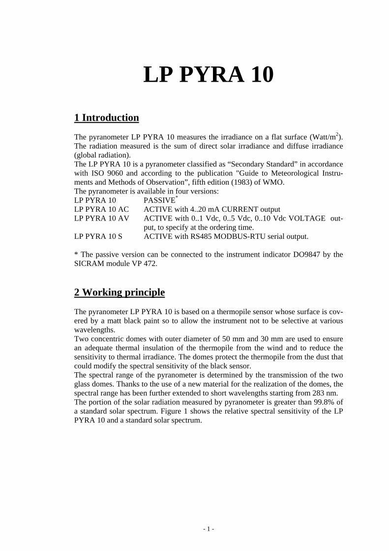
put, to specify at the ordering time. LP PYRA 10 S ACTIVE with RS485 MODBUS-RTU serial output. * The passive version can be connected to the instrument indicator DO9847 by the SICRAM module VP 472. 2 Working principle The pyranometer LP PYRA 10 is based on a thermopile sensor whose surface is cov-ered by a matt black paint so to allow the instrument not to be selective at various wavelengths. Two concentric domes with outer diameter of 50 mm and 30 mm are used to ensure an adequate thermal insulation of the thermopile from the wind and to reduce the sensitivity to thermal irradiance. The domes protect the thermopile from the dust that could modify the spectral sensitivity of the black sensor. The spectral range of the pyranometer is determined by the transmission of the two glass domes. Thanks to the use of a new material for the realization of the domes, the spectral range has been further extended to short wavelengths starting from 283 nm. The portion of the solar radiation measured by pyranometer is greater than 99.8% of a standard solar spectrum. Figure 1 shows the relative spectral sensitivity of the LP PYRA 10 and a standard solar spectrum.
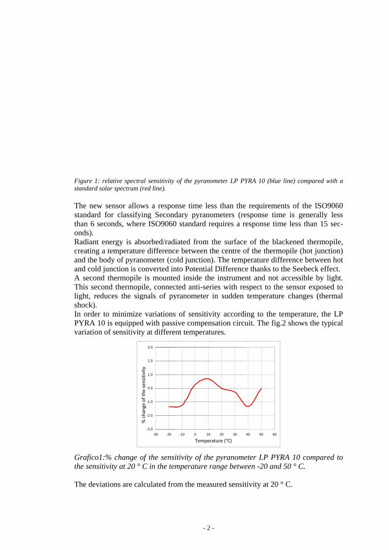
Figure 1: restandard sol The new standard fthan 6 seconds). Radiant encreating a and the boand cold juA second This seconlight, redushock). In order tPYRA 10 variation o
Grafico1:the sensiti The deviat
elative spectrlar spectrum (
sensor allowfor classifyconds, wher
nergy is abtemperatur
ody of pyranunction is cthermopile
nd thermopuces the sig
o minimizeis equipped
of sensitivit
% change oivity at 20 °
tions are ca
ral sensitivity (red line).
ws a responying Secondre ISO9060
bsorbed/radire differencnometer (coconverted ine is mountepile, connecgnals of py
e variationsd with passity at differen
of the sensiC in the tem
alculated fro
-3.0
-2.0
-1.0
0.0
1.0
2.0
3.0
-30 -20
Var
iazi
one
% d
ella
sen
sibi
lità
% c
hang
e of
the
sens
itivi
ty
- 2
of the pyrano
nse time ledary pyrano0 standard r
iated from e between t
old junctionnto Potentialed inside thcted anti-seryranometer
of sensitivive compennt temperatu
itivity of themperature r
om the meas
-10 0 10
TempeTemper
-
ometer LP PY
ss than the ometers (rerequires a re
the surfacethe centre o). The templ Differencee instrumenries with rein sudden
vity accordinsation circuures.
e pyranomerange betwe
sured sensit
20 30 4
eratura (C°) rature (°C)
YRA 10 (blue
requiremenesponse timesponse tim
e of the blaof the thermperature diffe thanks to tnt and not spect to thetemperatur
ing to the tuit. The fig.
eter LP PYReen -20 and
tivity at 20 °
40 50 60
line) compar
nts of the Ime is generame less than
ackened themopile (hot j
ference betwthe Seebeckaccessible be sensor expe changes
emperature.2 shows the
RA 10 comp
d 50 ° C.
° C.
red with a
ISO9060 ally less
n 15 sec-
ermopile, unction)
ween hot k effect. by light. posed to (thermal
, the LP e typical
pared to
- 3 -
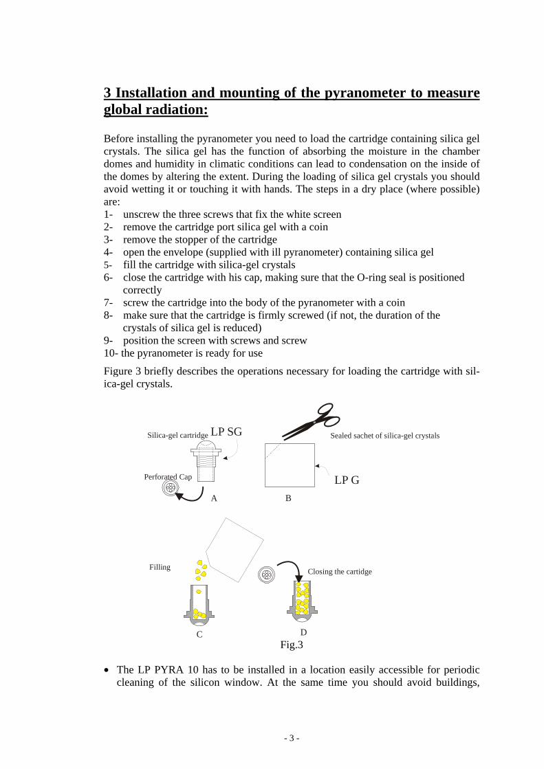
3 Installation and mounting of the pyranometer to measure global radiation: Before installing the pyranometer you need to load the cartridge containing silica gel crystals. The silica gel has the function of absorbing the moisture in the chamber domes and humidity in climatic conditions can lead to condensation on the inside of the domes by altering the extent. During the loading of silica gel crystals you should avoid wetting it or touching it with hands. The steps in a dry place (where possible) are: 1- unscrew the three screws that fix the white screen 2- remove the cartridge port silica gel with a coin 3- remove the stopper of the cartridge 4- open the envelope (supplied with ill pyranometer) containing silica gel 5- fill the cartridge with silica-gel crystals 6- close the cartridge with his cap, making sure that the O-ring seal is positioned correctly 7- screw the cartridge into the body of the pyranometer with a coin 8- make sure that the cartridge is firmly screwed (if not, the duration of the crystals of silica gel is reduced) 9- position the screen with screws and screw 10- the pyranometer is ready for use
Figure 3 briefly describes the operations necessary for loading the cartridge with sil-ica-gel crystals.
A B
C D
Silica-gel cartridge
Perforated Cap
Sealed sachet of silica-gel crystals
Filling Closing the cartidge
LP G
LP SG
Fig.3
• The LP PYRA 10 has to be installed in a location easily accessible for periodic
cleaning of the silicon window. At the same time you should avoid buildings,
- 4 -
trees or obstacles of any kind exceed the horizontal plane on which the pyranome-ter lies. In case this is not possible it is advisable to choose a location where the obstacles are lower than 5°. N.B. The presence of obstructions on the horizon line significantly affects the measurement of direct irradiance.
• The pyranometer should be located far from any kind of obstacle that can project the reflection of the sun (or shadow) on the same pyranometer.
• When the pyranometer is used without the white screen should be positioned so that the cable comes out from the North pole if you use it in the NORTH hemi-sphere, and from the SOUTHERN pole if you use it in the SOUTH hemisphere, according to the ISO TR9901 standard and other WMO recommendations. In any case, it is preferable to comply with WMO/ISO recommendations also when the screen is used.
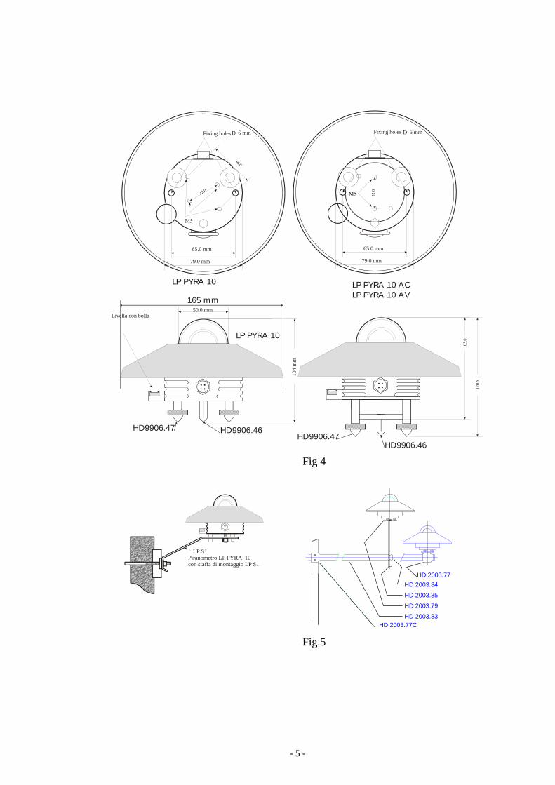
• For an accurate horizontal positioning, the pyranometer LP PYRA 10 is equipped with a spirit level, which adjustment is by two screws with lock nut that allows changing the pyranometer inclination. The fixing on a flat base can be performed by using two 6 mm diam. holes and 65 mm wheelbase. In order to access the holes, remove the screen and re-place it back after mounting, see figure 4.
• In order to facilitate the installation of the pyranometer, Delta Ohm provides on request a range of accessories illustrated in Figure 5. The installer must take care that the height of the mast does not exceed the floor of the pyranometer, not to in-troduce errors extent caused by reflections and shadows caused by the pole.
• It is better to insulate the pyranometer from its support, while ensuring that there is a good electrical contact to earth.
- 5 -
HD 2003.83HD 2003.77C
HD 2003.77
HD 2003.79
HD 2003.85
HD 2003.84
Fig 4
Fig.5
104
mm
50.0 mm
Fixing holes
Livella con bolla
65.0 mm
Fixing holes
65.0 mm
79.0 mm 79.0 mm
D D 6 mm 6 mm
165 mm
LP PYRA 10 ACLP PYRA 10 AV
LP PYRA 10
LP PYRA 10
HD9906.47HD9906.47
HD9906.46
HD9906.46
Μ5
Μ532.0
32.0
46.0
103.
0
120.
5
Piranometro LP PYRA 10con staffa di montaggio LP S1
LP S1
4 Electreading The LP PYPYRA AV• The LP• Version
is: 10
155-3
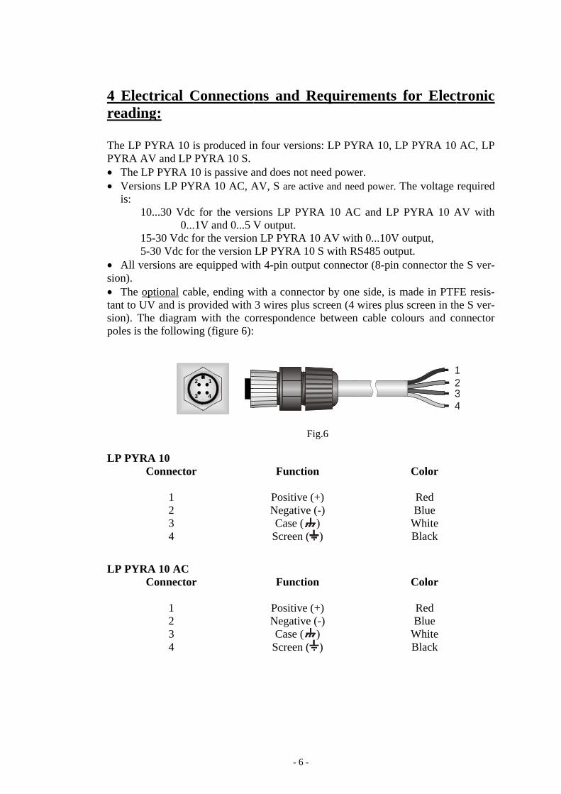
• All version). • The optant to UVsion). Thepoles is th
LP PYRAC
LP PYRAC
trical Cog:
YRA 10 is V and LP PYP PYRA 10 ns LP PYRA
...30 Vdc f0...1V
-30 Vdc for30 Vdc for trsions are eq
ptional cableV and is proe diagram whe following
A 10 Connector
1 2 3 4
A 10 AC Connector
1 2 3 4
2
3
onnectio
produced inYRA 10 S. is passive aA 10 AC, A
for the versV and 0...5 Vr the versionthe version quipped wit
e, ending wovided with with the cog (figure 6):
1
4
- 6
ons and
n four versi
and does noAV, S are ac
ions LP PYV output. n LP PYRALP PYRA th 4-pin out
with a conne3 wires plu
orresponden
Funct
PositiveNegativCase (
Screen
Funct
PositiveNegativCase (
Screen
-
Require
ions: LP PY
ot need powective and nee
YRA 10 AC
A 10 AV wit10 S with Rtput connec
ector by onus screen (4 nce between
Fig.6
ion
e (+) ve (-)
) ( )
ion
e (+) ve (-)
) ( )
ements f
YRA 10, LP
er. ed power. T
C and LP P
th 0...10V oRS485 outpuctor (8-pin c
e side, is mwires plus
n cable colo
for Elec
P PYRA 10
The voltage
PYRA 10 A
output, ut. connector th
made in PTFscreen in thours and co
Color
Red Blue
White Black
Color
Red Blue
White Black
23
1
4
tronic
AC, LP
required
AV with
he S ver-
FE resis-he S ver-onnector
23
1
4
•
LP PYRAC
Connectin
LP PYRAConnec
1 2 4 5 6 8
LP PYRAcally, the of the inst
A 10 AV Connector
1 2 3 4
ng scheme
1234 5 6
8
A 10 S ctor
A 10 is connsignal from
trument read
CBlu
for LP PYR
67
Power supPower sup
RR
NoNo
nected to a m pyranomeding in orde
C
Therm
ue
Temperacompens
- 7
Funct
(+) V(-) Vout and
(+) VScreen
RA 10 S
Fig
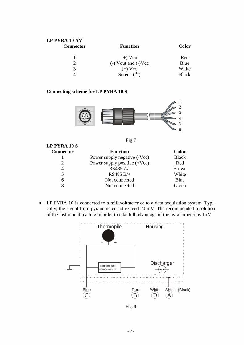
Function pply negativpply positiveRS485 A/-RS485 B/+ot connectedot connected
millivoltmeeter not exceer to take fu
Fig.
mopile
R
aturesation
-
ion
out d (-)Vcc
Vcc ( )
.7
ve (-Vcc) e (+Vcc)
d d
eter or to a eed 20 mV
ull advantag
. 8
B D
Hou
Di
Red Wh
CBR
BWB
G
data acquis. The recome of the pyr
AD
sing
ischarger
hite Shield
Color
Red Blue
White Black
45
321
6
Color Black Red rown
White Blue
Green
sition systemmmended reranometer, i
(Black)
m. Typi-esolution is 1μV.
- 8 -
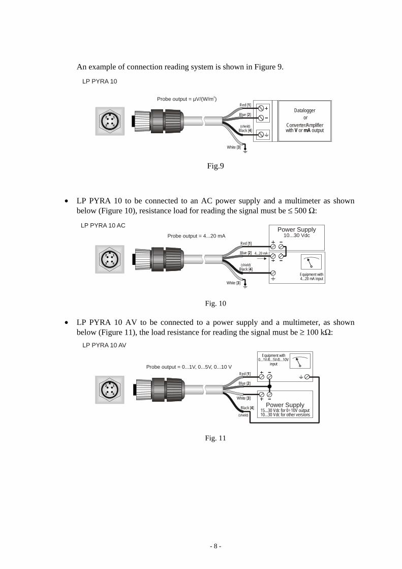
An example of connection reading system is shown in Figure 9.
Fig.9
• LP PYRA 10 to be connected to an AC power supply and a multimeter as shown below (Figure 10), resistance load for reading the signal must be ≤ 500 Ω:
Fig. 10
• LP PYRA 10 AV to be connected to a power supply and a multimeter, as shown
below (Figure 11), the load resistance for reading the signal must be ≥ 100 kΩ:
Fig. 11
LP PYRA 10
Red [ ]1
Blue [ ]2
Black [ ]4
White [ ]3
Probe output µV/(W/m )2 =
12
3 4 (shield) Converter/Amplifierwith or outputV mA
Dataloggeror
Red [ ]1
Blue [ ]2
White [ ]3
Power SupplyLP PYRA 10 AC10...30 Vdc
4...20 mA
Probe output = 4...20 mA
12
3 4
Black [ ]4(shield)
Equipment with4...20 mA input
LP PYRA 10 AV
Red [ ]1
Blue [ ]2
Black [ ]4
White [ ]3
Power Supply
Probe output 0...1V, 0...5V, 0...10 V =
(shield)
12
3 4
10...30 Vdc for other versions15...30 Vdc for 0÷10V output
Equipment with0...1V/0...5V/0...10V
input
- 9 -
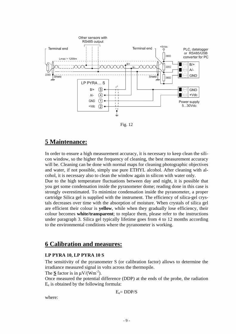
Fig. 12
5 Maintenance: In order to ensure a high measurement accuracy, it is necessary to keep clean the sili-con window, so the higher the frequency of cleaning, the best measurement accuracy will be. Cleaning can be done with normal maps for cleaning photographic objectives and water, if not possible, simply use pure ETHYL alcohol. After cleaning with al-cohol, it is necessary also to clean the window again in silicon with water only. Due to the high temperature fluctuations between day and night, it is possible that you get some condensation inside the pyranometer dome; reading done in this case is strongly overestimated. To minimize condensation inside the pyranometer, a proper cartridge Silica gel is supplied with the instrument. The efficiency of silica-gel crys-tals decreases over time with the absorption of moisture. When crystals of silica gel are efficient their colour is yellow, while when they gradually lose efficiency, their colour becomes white/transparent; to replace them, please refer to the instructions under paragraph 3. Silica gel typically lifetime goes from 4 to 12 months according to the environmental conditions where the pyranometer is working. 6 Calibration and measures:
LP PYRA 10, LP PYRA 10 S The sensitivity of the pyranometer S (or calibration factor) allows to determine the irradiance measured signal in volts across the thermopile. The S factor is in μV/(Wm-2). Once measured the potential difference (DDP) at the ends of the probe, the radiation Ee is obtained by the following formula:
Ee= DDP/S where:

- 10 -
Ee: is the Radiation expressed in W/m2, DDP: is the difference of potential expressed in μV measure by a multimeter, S: is the calibration factor reported on the pyranometer label (and on the calibra-
tion report) in μV/(W/m2).
LP PYRA 10 AC The sensitivity of the pyranometer is factory adjusted so that
4..20 mA = 0.. 2000 W/m2 (0…4000 W/m2 on request)
To get the value of radiation once you know the current (Iout) drawn by the instru-ment, you should apply the following formula:
)4(125 mAIE oute −⋅=
)4(250 mAIE oute −⋅= with full scale 4000 W/m2 where:
Ee: is the Radiation expressed in W/m2, Iout: is the current in mA absorbed by the instrument
LP PYRA 10 AV The sensitivity of the pyranometer is factory adjusted so that, depending on the ver-sion you have chosen, you get: 0..1 V = 0.. 2000 W/m2 (0…4000 W/m2 on request) 0..5 V = 0.. 2000 W/m2 (0…4000 W/m2 on request) 0..10 V = 0.. 2000 W/m2 (0…4000 W/m2 on request) Once you know the output voltage (Vout) of the instrument, to obtain the value of ir-radiation should apply the following formula:
oute VE ⋅=2000 for the version 0…1 V
oute VE ⋅=4000 for the version 0…1 V with full scale 4000 W/m2
oute VE ⋅=400 for the version 0…5 V
oute VE ⋅=800 for the version 0…5 V with full scale 4000 W/m2
oute VE ⋅=200 for the version 0…10 V
oute VE ⋅=400 for the version 0…10 V with full scale 4000 W/m2
- 11 -
where: Ee: is the Radiation expressed in W/m2, Vout: is the output voltage (in Volts) measured with the voltmeter
Each pyranometer is individually factory calibrated and is distinguished by its cali-bration factor. To take full advantage of the LP PYRA 10 features, we recommend performing the calibration annually. The instruments present in the metrology laboratory of Photo-Radiometry at Delta Ohm srl allows the calibration of the pyranometer according to the requirements of WMO, and ensures the traceability of measurements to international standards.
- 12 -
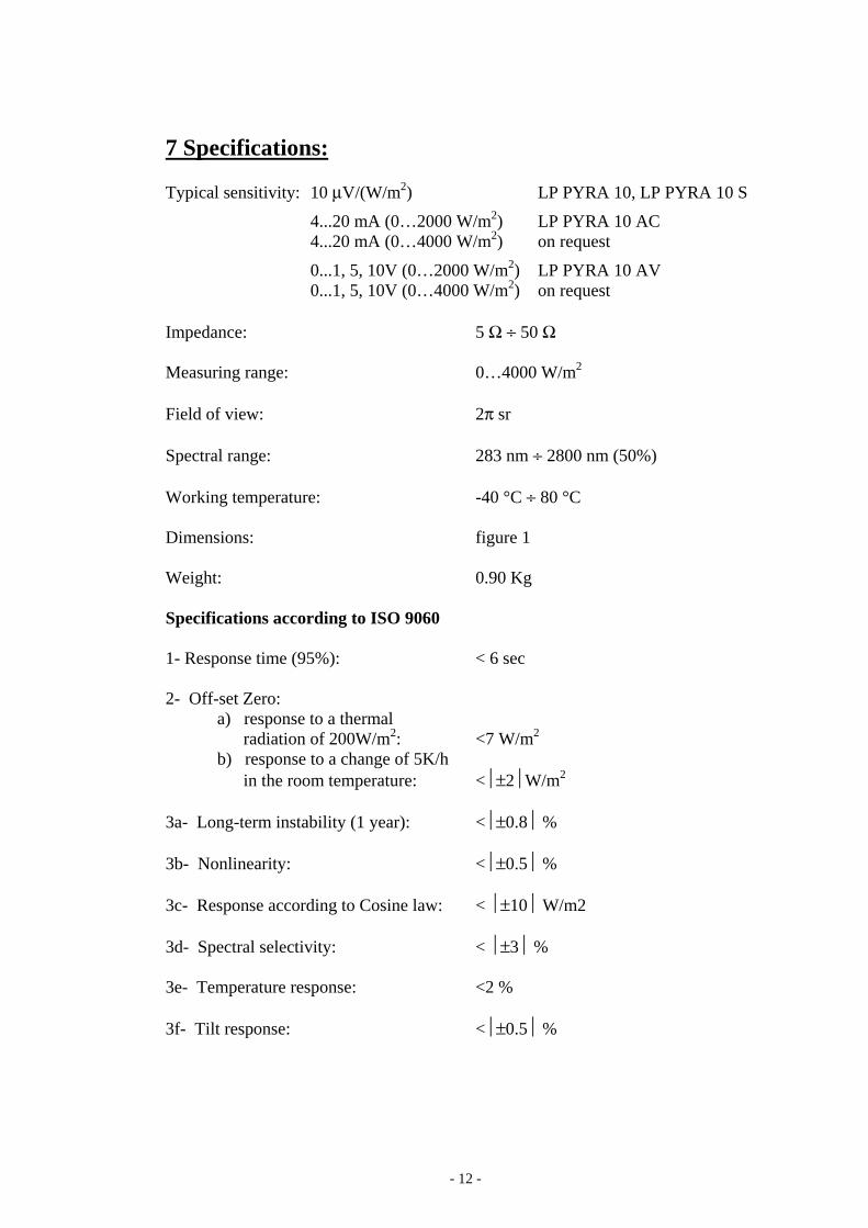
7 Specifications: Typical sensitivity: 10 μV/(W/m2) LP PYRA 10, LP PYRA 10 S
4...20 mA (0…2000 W/m2) LP PYRA 10 AC 4...20 mA (0…4000 W/m2) on request
0...1, 5, 10V (0…2000 W/m2) LP PYRA 10 AV 0...1, 5, 10V (0…4000 W/m2) on request Impedance: 5 Ω ÷ 50 Ω Measuring range: 0…4000 W/m2 Field of view: 2π sr Spectral range: 283 nm ÷ 2800 nm (50%) Working temperature: -40 °C ÷ 80 °C Dimensions: figure 1 Weight: 0.90 Kg Specifications according to ISO 9060 1- Response time (95%): < 6 sec 2- Off-set Zero:
a) response to a thermal radiation of 200W/m2: <7 W/m2 b) response to a change of 5K/h in the room temperature: <⏐±2⏐W/m2
3a- Long-term instability (1 year): <⏐±0.8⏐ % 3b- Nonlinearity: <⏐±0.5⏐ % 3c- Response according to Cosine law: < ⏐±10⏐ W/m2 3d- Spectral selectivity: < ⏐±3⏐ % 3e- Temperature response: <2 % 3f- Tilt response: <⏐±0.5⏐ %
- 13 -
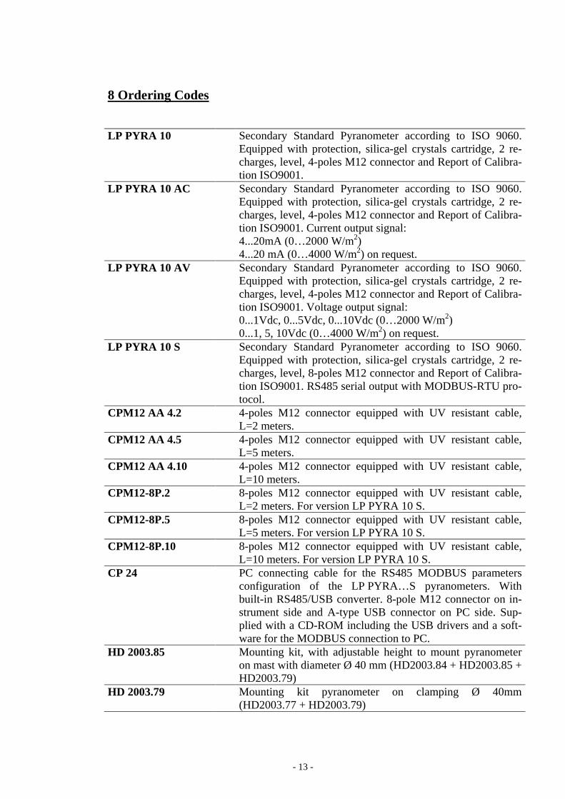
8 Ordering Codes LP PYRA 10 Secondary Standard Pyranometer according to ISO 9060.
Equipped with protection, silica-gel crystals cartridge, 2 re-charges, level, 4-poles M12 connector and Report of Calibra-tion ISO9001.
LP PYRA 10 AC Secondary Standard Pyranometer according to ISO 9060. Equipped with protection, silica-gel crystals cartridge, 2 re-charges, level, 4-poles M12 connector and Report of Calibra-tion ISO9001. Current output signal: 4...20mA (0…2000 W/m2) 4...20 mA (0…4000 W/m2) on request.
LP PYRA 10 AV Secondary Standard Pyranometer according to ISO 9060. Equipped with protection, silica-gel crystals cartridge, 2 re-charges, level, 4-poles M12 connector and Report of Calibra-tion ISO9001. Voltage output signal: 0...1Vdc, 0...5Vdc, 0...10Vdc (0…2000 W/m2) 0...1, 5, 10Vdc (0…4000 W/m2) on request.
LP PYRA 10 S Secondary Standard Pyranometer according to ISO 9060. Equipped with protection, silica-gel crystals cartridge, 2 re-charges, level, 8-poles M12 connector and Report of Calibra-tion ISO9001. RS485 serial output with MODBUS-RTU pro-tocol.
CPM12 AA 4.2 4-poles M12 connector equipped with UV resistant cable, L=2 meters.
CPM12 AA 4.5 4-poles M12 connector equipped with UV resistant cable, L=5 meters.
CPM12 AA 4.10 4-poles M12 connector equipped with UV resistant cable, L=10 meters.
CPM12-8P.2 8-poles M12 connector equipped with UV resistant cable, L=2 meters. For version LP PYRA 10 S.
CPM12-8P.5 8-poles M12 connector equipped with UV resistant cable, L=5 meters. For version LP PYRA 10 S.
CPM12-8P.10 8-poles M12 connector equipped with UV resistant cable, L=10 meters. For version LP PYRA 10 S.
CP 24 PC connecting cable for the RS485 MODBUS parameters configuration of the LP PYRA…S pyranometers. With built-in RS485/USB converter. 8-pole M12 connector on in-strument side and A-type USB connector on PC side. Sup-plied with a CD-ROM including the USB drivers and a soft-ware for the MODBUS connection to PC.
HD 2003.85 Mounting kit, with adjustable height to mount pyranometer on mast with diameter Ø 40 mm (HD2003.84 + HD2003.85 + HD2003.79)
HD 2003.79 Mounting kit pyranometer on clamping Ø 40mm (HD2003.77 + HD2003.79)

- 14 -
HD 2003.77 Clamping for mast Ø 40mm LP SP1 Protective screen plastic UV resistant. LURAN S777K by
BASF® LP S1 Bracket positioning pyranometer LP PYRA 10, suitable for
mast with a maximum diameter of 50mm. LP S6 Kit for the installation of LP PYRA 10 pyranometers. The
kit includes: 1 m mast (LP S6.05), base fitting (LP S6.04), graduated support plate (LP S6.01), bracket for HD9007 or HD32MTT.03.C (HD 9007T29.1), bracket for pyranometers (LP S6.03).
LP SG Cartridge containing silica gel crystals, complete with O-ring and cap.
LP G Pack of 5 cartridges of silica gel crystals.
- 1 -
LP PYRA … S / LP PYRHE 16 S ENGLISH RS485 MODBUS-RTU connection Rev. 2.0 – 31/01/2017
SETTING THE RS485 COMMUNICATION PARAMETERS OF LP PYRA…S PYRANOMETERS AND LP PYRHE 16 S PYRHELIOMETER WITH A STANDARD COMMUNICATION PROGRAM Before connecting the sensor to the RS485 network, an address must be assigned and the communication parameters must be set, if different from the factory preset.
The setting of the parameters is performed by connecting the sensor to the PC in one of the following two ways:
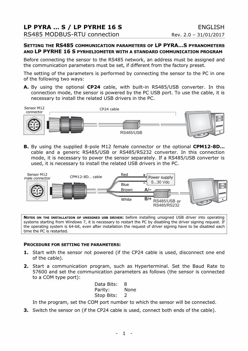
A. By using the optional CP24 cable, with built-in RS485/USB converter. In this connection mode, the sensor is powered by the PC USB port. To use the cable, it is necessary to install the related USB drivers in the PC.
B. By using the supplied 8-pole M12 female connector or the optional CPM12-8D… cable and a generic RS485/USB or RS485/RS232 converter. In this connection mode, it is necessary to power the sensor separately. If a RS485/USB converter is used, it is necessary to install the related USB drivers in the PC.
NOTES ON THE INSTALLATION OF UNSIGNED USB DRIVER: before installing unsigned USB driver into operating systems starting from Windows 7, it is necessary to restart the PC by disabling the driver signing request. If the operating system is 64-bit, even after installation the request of driver signing have to be disabled each time the PC is restarted.
PROCEDURE FOR SETTING THE PARAMETERS:
1. Start with the sensor not powered (if the CP24 cable is used, disconnect one end of the cable).
2. Start a communication program, such as Hyperterminal. Set the Baud Rate to 57600 and set the communication parameters as follows (the sensor is connected to a COM type port):
Data Bits: 8 Parity: None Stop Bits: 2
In the program, set the COM port number to which the sensor will be connected.
3. Switch the sensor on (if the CP24 cable is used, connect both ends of the cable).
Power supply
or
CPM12-8D… cable Red
Blue Brown
White
Sensor M12 male connector
CP24 cable Sensor M12 connector
- 2 -
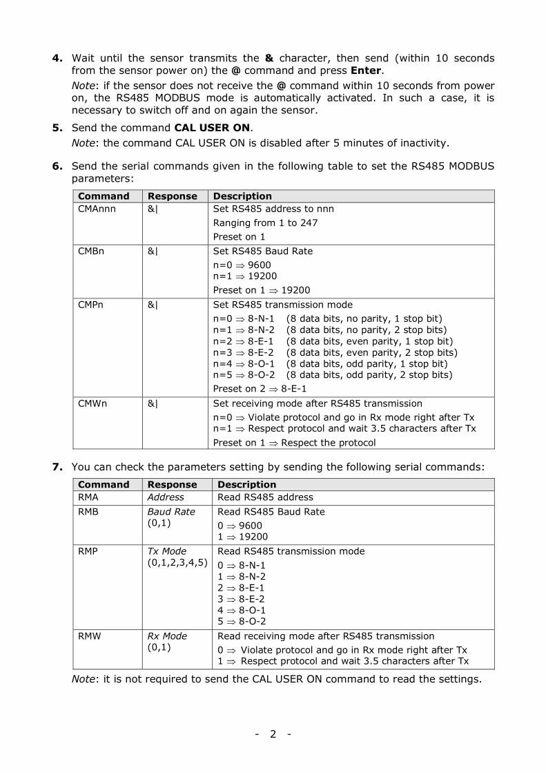
4. Wait until the sensor transmits the & character, then send (within 10 seconds from the sensor power on) the @ command and press Enter.
Note: if the sensor does not receive the @ command within 10 seconds from power on, the RS485 MODBUS mode is automatically activated. In such a case, it is necessary to switch off and on again the sensor.
5. Send the command CAL USER ON. Note: the command CAL USER ON is disabled after 5 minutes of inactivity.
6. Send the serial commands given in the following table to set the RS485 MODBUS parameters:
Command Response Description CMAnnn &| Set RS485 address to nnn
Ranging from 1 to 247 Preset on 1
CMBn &| Set RS485 Baud Rate n=0 ⇒ 9600 n=1 ⇒ 19200 Preset on 1 ⇒ 19200
CMPn &| Set RS485 transmission mode n=0 ⇒ 8-N-1 (8 data bits, no parity, 1 stop bit) n=1 ⇒ 8-N-2 (8 data bits, no parity, 2 stop bits) n=2 ⇒ 8-E-1 (8 data bits, even parity, 1 stop bit) n=3 ⇒ 8-E-2 (8 data bits, even parity, 2 stop bits) n=4 ⇒ 8-O-1 (8 data bits, odd parity, 1 stop bit) n=5 ⇒ 8-O-2 (8 data bits, odd parity, 2 stop bits) Preset on 2 ⇒ 8-E-1
CMWn &| Set receiving mode after RS485 transmission n=0 ⇒ Violate protocol and go in Rx mode right after Tx n=1 ⇒ Respect protocol and wait 3.5 characters after Tx Preset on 1 ⇒ Respect the protocol
7. You can check the parameters setting by sending the following serial commands:
Command Response Description RMA Address Read RS485 address RMB Baud Rate
(0,1) Read RS485 Baud Rate 0 ⇒ 9600 1 ⇒ 19200
RMP Tx Mode (0,1,2,3,4,5)
Read RS485 transmission mode 0 ⇒ 8-N-1 1 ⇒ 8-N-2 2 ⇒ 8-E-1 3 ⇒ 8-E-2 4 ⇒ 8-O-1 5 ⇒ 8-O-2
RMW Rx Mode (0,1)
Read receiving mode after RS485 transmission 0 ⇒ Violate protocol and go in Rx mode right after Tx 1 ⇒ Respect protocol and wait 3.5 characters after Tx
Note: it is not required to send the CAL USER ON command to read the settings.
- 3 -
READING OF THE MEASURES WITH THE MODBUS-RTU PROTOCOL WHEN THE SENSOR IS IN OPERATING CONDITIONS (INSTALLED IN A NETWORK) In MODBUS mode, you can read the values measured by the sensor through the function code 04h (Read Input Registers). The following table lists the quantities available with the appropriate register address:
Address Quantity Format 0 Temperature in °C (x10) [if available in the model] 16-bit Integer
1 Temperature in °F (x10) [if available in the model] 16-bit Integer
2 Solar radiation in W/m2 16-bit Integer
3 Status register bit0=1 ⇒ solar radiation measurement error bit1=1 ⇒ temperature measurement error bit2=1 ⇒ configuration data error bit3=1 ⇒ program memory error
16-bit Integer
4 Average solar radiation in W/m2 The average refers to the last 4 measures
16-bit Integer
5 Signal (in mV x 100) generated by the sensor 16-bit Integer
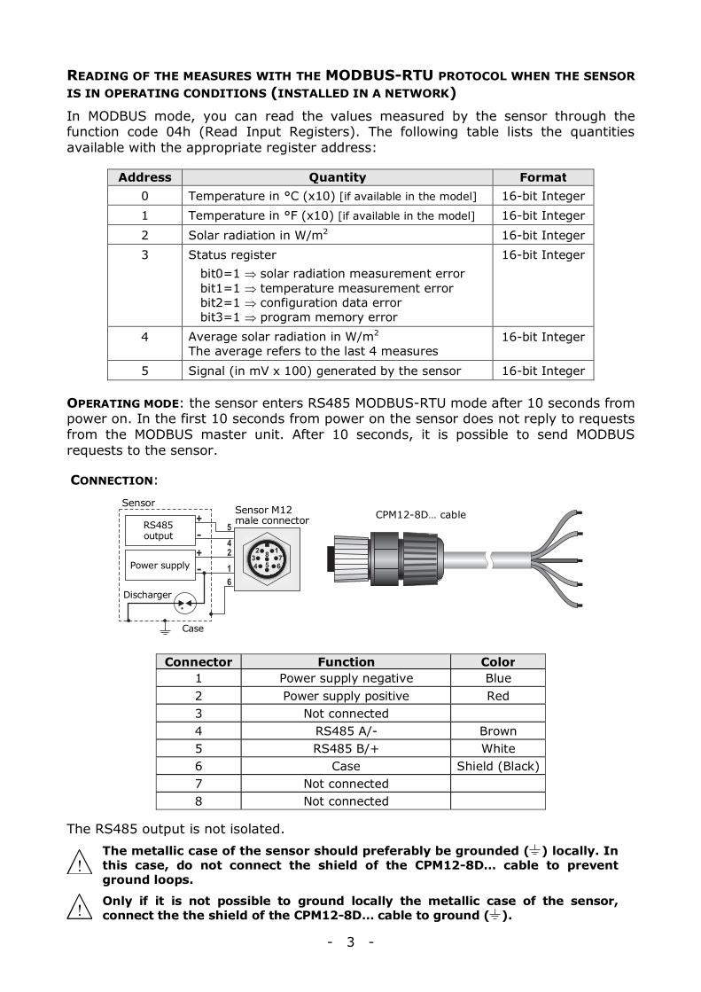
OPERATING MODE: the sensor enters RS485 MODBUS-RTU mode after 10 seconds from power on. In the first 10 seconds from power on the sensor does not reply to requests from the MODBUS master unit. After 10 seconds, it is possible to send MODBUS requests to the sensor.
CONNECTION:
Connector Function Color 1 Power supply negative Blue 2 Power supply positive Red 3 Not connected 4 RS485 A/- Brown 5 RS485 B/+ White 6 Case Shield (Black) 7 Not connected 8 Not connected
The RS485 output is not isolated.
The metallic case of the sensor should preferably be grounded ( ) locally. In this case, do not connect the shield of the CPM12-8D… cable to prevent ground loops.
Only if it is not possible to ground locally the metallic case of the sensor, connect the the shield of the CPM12-8D… cable to ground ( ).
Sensor
Discharger
Case
RS485 output
Power supply
Sensor M12 male connector CPM12-8D… cable
- 4 -
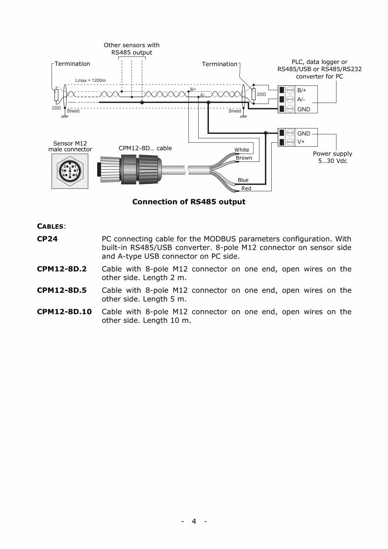
Connection of RS485 output
CABLES:
CP24 PC connecting cable for the MODBUS parameters configuration. With built-in RS485/USB converter. 8-pole M12 connector on sensor side and A-type USB connector on PC side.
CPM12-8D.2 Cable with 8-pole M12 connector on one end, open wires on the other side. Length 2 m.
CPM12-8D.5 Cable with 8-pole M12 connector on one end, open wires on the other side. Length 5 m.
CPM12-8D.10 Cable with 8-pole M12 connector on one end, open wires on the other side. Length 10 m.
Power supply 5…30 Vdc
Red Blue
Brown White CPM12-8D… cable
Sensor M12 male connector
PLC, data logger or RS485/USB or RS485/RS232
converter for PC
Other sensors with RS485 output
Termination Termination
- 1 -
LP PYRA … S12 series ENGLISH Pyranometers with SDI-12 output Rev. 1.1 – 05/10/2016
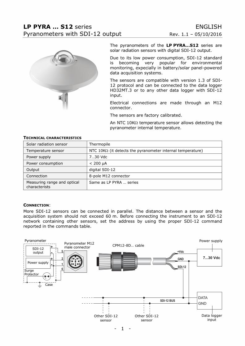
The pyranometers of the LP PYRA…S12 series are solar radiation sensors with digital SDI-12 output.
Due to its low power consumption, SDI-12 standard is becoming very popular for environmental monitoring, expecially in battery/solar panel-powered data acquisition systems.
The sensors are compatible with version 1.3 of SDI-12 protocol and can be connected to the data logger HD32MT.3 or to any other data logger with SDI-12 input.
Electrical connections are made through an M12 connector.
The sensors are factory calibrated.
An NTC 10KΩ temperature sensor allows detecting the pyranometer internal temperature.
TECHNICAL CHARACTERISTICS Solar radiation sensor Thermopile
Temperature sensor NTC 10KΩ (it detects the pyranometer internal temperature)
Power supply 7…30 Vdc
Power consumption < 200 µA
Output digital SDI-12
Connection 8-pole M12 connector
Measuring range and optical characterists
Same as LP PYRA … series
CONNECTION: More SDI-12 sensors can be connected in parallel. The distance between a sensor and the acquisition system should not exceed 60 m. Before connecting the instrument to an SDI-12 network containing other sensors, set the address by using the proper SDI-12 command reported in the commands table.
Data logger
input
Pyranometer
Surge Protector
Case
SDI-12 output
Power supply
Pyranometer M12 male connector CPM12-8D… cable
Power supply
Other SDI-12 sensor
Other SDI-12 sensor
- 2 -
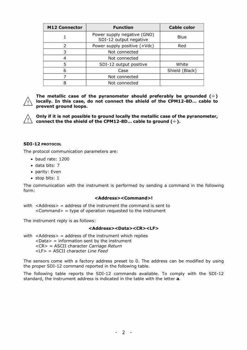
M12 Connector Function Cable color
1 Power supply negative (GND) SDI-12 output negative Blue
2 Power supply positive (+Vdc) Red 3 Not connected 4 Not connected 5 SDI-12 output positive White 6 Case Shield (Black) 7 Not connected 8 Not connected
The metallic case of the pyranometer should preferably be grounded ( ) locally. In this case, do not connect the shield of the CPM12-8D… cable to prevent ground loops.
Only if it is not possible to ground locally the metallic case of the pyranometer, connect the the shield of the CPM12-8D… cable to ground ( ).
SDI-12 PROTOCOL
The protocol communication parameters are:
• baud rate: 1200 • data bits: 7 • parity: Even • stop bits: 1
The communication with the instrument is performed by sending a command in the following form:
<Address><Command>!
with <Address> = address of the instrument the command is sent to <Command> = type of operation requested to the instrument
The instrument reply is as follows:
<Address><Data><CR><LF>
with <Address> = address of the instrument which replies <Data> = information sent by the instrument <CR> = ASCII character Carriage Return <LF> = ASCII character Line Feed
The sensors come with a factory address preset to 0. The address can be modified by using the proper SDI-12 command reported in the following table.
The following table reports the SDI-12 commands available. To comply with the SDI-12 standard, the instrument address is indicated in the table with the letter a.
- 3 -
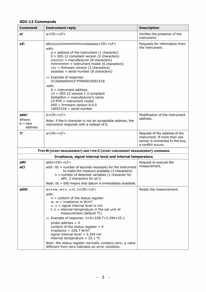
SDI-12 Commands
Command Instrument reply Description
a! a<CR><LF> Verifies the presence of the instrument.
aI! allccccccccmmmmmmvvvssssssss<CR><LF> with: a = address of the instrument (1 character) ll = SDI-12 compliant version (2 characters) cccccccc = manufacturer (8 characters) mmmmmm = instrument model (6 characters) vvv = firmware version (3 characters) ssssssss = serial number (8 characters)
⇒ Example of response: 013DeltaOhmLP-PYRA0016051518 with: 0 = instrument address 13 = SDI-12 version 1.3 compliant DeltaOhm = manufacturer’s name LP-PYR = instrument model A00 = firmware version A.0.0 16051518 = serial number
Requests for information from the instrument.
aAb! Where: b = new
address
b<CR><LF>
Note: if the b character is not an acceptable address, the instrument responds with a instead of b.
Modification of the instrument address.
?! a<CR><LF> Request of the address of the instrument. If more than one sensor is connected to the bus, a conflict occurs.
TYPE M (START MEASUREMENT) AND TYPE C (START CONCURRENT MEASUREMENT) COMMANDS
Irradiance, signal internal level and internal temperature
aM! aC!
atttn<CR><LF> with: ttt = number of seconds necessary for the instrument
to make the measure available (3 characters) n = number of detected variables (1 character for
aM!, 2 characters for aC!) Note: ttt = 000 means that datum is immediately available.
Request to execute the measurement.
aD0! a+n+w…w+v…v+t…t<CR><LF> with: n = content of the status register w…w = irradiance in W/m2 v…v = signal internal level in mV
t…t = internal temperature in the set unit of measurement (default °C)
⇒ Example of response: 0+0+228.7+3.294+25.1 probe address = 0 content of the status register = 0 irradiance = 228.7 W/m2 signal internal level = 3.294 mV internal temperature = 25.1 °C Note: the status register normally contains zero; a value different from zero indicates an error condition.
Reads the measurement.
- 4 -
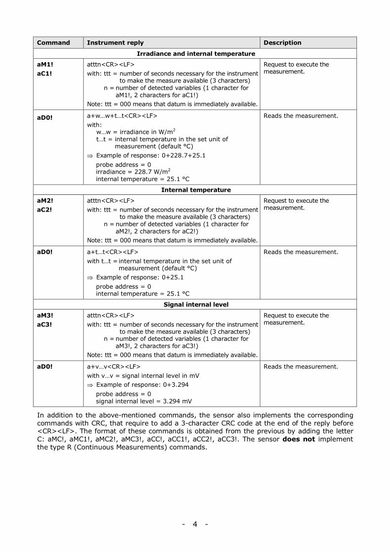
Command Instrument reply Description
Irradiance and internal temperature
aM1! aC1!
atttn<CR><LF> with: ttt = number of seconds necessary for the instrument
to make the measure available (3 characters) n = number of detected variables (1 character for
aM1!, 2 characters for aC1!) Note: ttt = 000 means that datum is immediately available.
Request to execute the measurement.
aD0! a+w…w+t…t<CR><LF> with: w…w = irradiance in W/m2
t…t = internal temperature in the set unit of measurement (default °C)
⇒ Example of response: 0+228.7+25.1 probe address = 0 irradiance = 228.7 W/m2 internal temperature = 25.1 °C
Reads the measurement.
Internal temperature
aM2! aC2!
atttn<CR><LF> with: ttt = number of seconds necessary for the instrument
to make the measure available (3 characters) n = number of detected variables (1 character for
aM2!, 2 characters for aC2!) Note: ttt = 000 means that datum is immediately available.
Request to execute the measurement.
aD0! a+t…t<CR><LF> with t…t = internal temperature in the set unit of
measurement (default °C) ⇒ Example of response: 0+25.1 probe address = 0 internal temperature = 25.1 °C
Reads the measurement.
Signal internal level
aM3! aC3!
atttn<CR><LF> with: ttt = number of seconds necessary for the instrument
to make the measure available (3 characters) n = number of detected variables (1 character for
aM3!, 2 characters for aC3!) Note: ttt = 000 means that datum is immediately available.
Request to execute the measurement.
aD0! a+v…v<CR><LF> with v…v = signal internal level in mV ⇒ Example of response: 0+3.294 probe address = 0 signal internal level = 3.294 mV
Reads the measurement.
In addition to the above-mentioned commands, the sensor also implements the corresponding commands with CRC, that require to add a 3-character CRC code at the end of the reply before <CR><LF>. The format of these commands is obtained from the previous by adding the letter C: aMC!, aMC1!, aMC2!, aMC3!, aCC!, aCC1!, aCC2!, aCC3!. The sensor does not implement the type R (Continuous Measurements) commands.
- 5 -
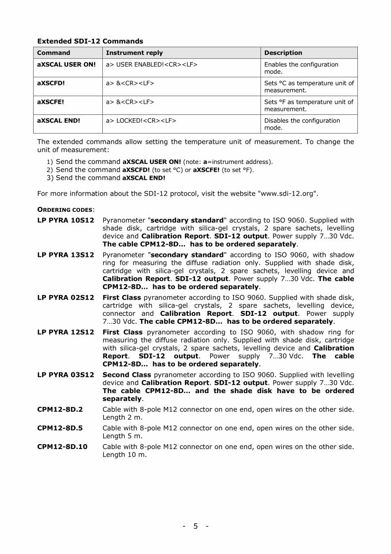
Extended SDI-12 Commands
Command Instrument reply Description
aXSCAL USER ON! a> USER ENABLED!<CR><LF> Enables the configuration mode.
aXSCFD! a> &<CR><LF> Sets °C as temperature unit of measurement.
aXSCFE! a> &<CR><LF> Sets °F as temperature unit of measurement.
aXSCAL END! a> LOCKED!<CR><LF> Disables the configuration mode.
The extended commands allow setting the temperature unit of measurement. To change the unit of measurement:
1) Send the command aXSCAL USER ON! (note: a=instrument address). 2) Send the command aXSCFD! (to set °C) or aXSCFE! (to set °F). 3) Send the command aXSCAL END!
For more information about the SDI-12 protocol, visit the website "www.sdi-12.org".
ORDERING CODES: LP PYRA 10S12 Pyranometer "secondary standard" according to ISO 9060. Supplied with
shade disk, cartridge with silica-gel crystals, 2 spare sachets, levelling device and Calibration Report. SDI-12 output. Power supply 7…30 Vdc. The cable CPM12-8D… has to be ordered separately.
LP PYRA 13S12 Pyranometer "secondary standard" according to ISO 9060, with shadow ring for measuring the diffuse radiation only. Supplied with shade disk, cartridge with silica-gel crystals, 2 spare sachets, levelling device and Calibration Report. SDI-12 output. Power supply 7…30 Vdc. The cable CPM12-8D… has to be ordered separately.
LP PYRA 02S12 First Class pyranometer according to ISO 9060. Supplied with shade disk, cartridge with silica-gel crystals, 2 spare sachets, levelling device, connector and Calibration Report. SDI-12 output. Power supply 7…30 Vdc. The cable CPM12-8D… has to be ordered separately.
LP PYRA 12S12 First Class pyranometer according to ISO 9060, with shadow ring for measuring the diffuse radiation only. Supplied with shade disk, cartridge with silica-gel crystals, 2 spare sachets, levelling device and Calibration Report. SDI-12 output. Power supply 7…30 Vdc. The cable CPM12-8D… has to be ordered separately.
LP PYRA 03S12 Second Class pyranometer according to ISO 9060. Supplied with levelling device and Calibration Report. SDI-12 output. Power supply 7…30 Vdc. The cable CPM12-8D… and the shade disk have to be ordered separately.
CPM12-8D.2 Cable with 8-pole M12 connector on one end, open wires on the other side. Length 2 m.
CPM12-8D.5 Cable with 8-pole M12 connector on one end, open wires on the other side. Length 5 m.
CPM12-8D.10 Cable with 8-pole M12 connector on one end, open wires on the other side. Length 10 m.