low water fgd technologies - united states energy … water fgd... · 1 introduction low water fgd...
TRANSCRIPT

Low water FGD technologies
Anne M Carpenter
CCC/210 ISBN 978-92-9029-530-3
November 2012
copyright © IEA Clean Coal Centre
Abstract
Conventional flue gas desulphurisation (FGD) systems require large supplies of water. Technologieswhich reduce water usage are becoming more important with the large number of FGD systems beinginstalled in response to ever tightening emission regulations. Reducing water loss is particularlyimportant in arid regions of the world. This report reviews commercial and near commercial lowwater FGD processes for coal-fired power plants, including dry, semi-dry and multi-pollutanttechnologies. Wet scrubbers, the most widely deployed FGD technology, account for around 10–15%of the water losses in power plants with water cooling systems. This figure is considerably higherwhen dry/air cooling systems are employed. The evaporative water losses can be reduced by some40–50% when the flue gas is cooled before it enters the wet scrubber, a common practice in Europeand Japan. Technologies are under development to capture over 20% of the water in the flue gasexiting the wet scrubber, enabling the power plant to become a water supplier instead of a consumer.The semi-dry spray dry scrubbers and circulating dry scrubbers consume some 60% less water thanconventional wet scrubbers. The commercial dry sorbent injection processes have the lowest waterconsumption, consuming no water, or a minimal amount if the sorbent needs hydrating or the flue gasis humidified to improve performance. Commercial multi-pollutant systems are available thatconsume no water.

Acronyms and abbreviations
2 IEA CLEAN COAL CENTRE
ABS ammonium bisulphateAC activated cokeACI activated carbon injectionCapEx capital expenditureCCS carbon capture and storageCDS circulating dry scrubberCFB circulating fluidised bed CFD computational fluid dynamicsDSI duct sorbent injectionESI economiser sorbent injectionESP electrostatic precipitatorFGD flue gas desulphurisationFSI furnace sorbent injectiongal gallonGSA gas suspension absorptionID induced draftO&M operation and maintenanceOpEx operating expenditureppm parts per millionppmv parts per million by volumePRB Powder River Basin (USA)SCR selective catalytic reductionSDS spray dry scrubberSNCR selective non-catalytic reductionSR stoichiometric ratioSRS sulphur reactor systemTMC transport membrane condenser
Conversionlb/Btu to kg/kJ multiply by 0.4299 (that is, 0.4536/1.055)
Contents
3Low water FGD technologies
Acronyms and abbreviations . . . . . . . . . . . . . . . . . . . . . . . . . . . . . . . . . . . . . . . . . . . . . . . . 2
Contents. . . . . . . . . . . . . . . . . . . . . . . . . . . . . . . . . . . . . . . . . . . . . . . . . . . . . . . . . . . . . . . . 3
1 Introduction . . . . . . . . . . . . . . . . . . . . . . . . . . . . . . . . . . . . . . . . . . . . . . . . . . . . . . . . . 5
2 FGD fundamentals . . . . . . . . . . . . . . . . . . . . . . . . . . . . . . . . . . . . . . . . . . . . . . . . . . . . 72.1 Chemistry . . . . . . . . . . . . . . . . . . . . . . . . . . . . . . . . . . . . . . . . . . . . . . . . . . . . . . . 8
2.1.1 Calcium-based sorbents . . . . . . . . . . . . . . . . . . . . . . . . . . . . . . . . . . . . . . 92.1.2 Sodium-based sorbents . . . . . . . . . . . . . . . . . . . . . . . . . . . . . . . . . . . . . . 10
2.2 CO2 emissions. . . . . . . . . . . . . . . . . . . . . . . . . . . . . . . . . . . . . . . . . . . . . . . . . . . 112.3 By-product utilisation . . . . . . . . . . . . . . . . . . . . . . . . . . . . . . . . . . . . . . . . . . . . . 11
3 Wet scrubbers . . . . . . . . . . . . . . . . . . . . . . . . . . . . . . . . . . . . . . . . . . . . . . . . . . . . . . . 133.1 Limestone wet scrubbers . . . . . . . . . . . . . . . . . . . . . . . . . . . . . . . . . . . . . . . . . . 153.2 Reducing evaporative water losses . . . . . . . . . . . . . . . . . . . . . . . . . . . . . . . . . . . 163.3 Recovery of water vapour . . . . . . . . . . . . . . . . . . . . . . . . . . . . . . . . . . . . . . . . . . 17
3.3.1 Condensing heat exchangers. . . . . . . . . . . . . . . . . . . . . . . . . . . . . . . . . . 183.3.2 Membranes . . . . . . . . . . . . . . . . . . . . . . . . . . . . . . . . . . . . . . . . . . . . . . . 193.3.3 Liquid desiccants . . . . . . . . . . . . . . . . . . . . . . . . . . . . . . . . . . . . . . . . . . 21
4 Dry scrubbers . . . . . . . . . . . . . . . . . . . . . . . . . . . . . . . . . . . . . . . . . . . . . . . . . . . . . . . 234.1 Spray dry scrubbers . . . . . . . . . . . . . . . . . . . . . . . . . . . . . . . . . . . . . . . . . . . . . . 234.2 Duct spray dry process . . . . . . . . . . . . . . . . . . . . . . . . . . . . . . . . . . . . . . . . . . . . 254.3 Circulating dry scrubbers . . . . . . . . . . . . . . . . . . . . . . . . . . . . . . . . . . . . . . . . . . 25
4.3.1 Circulating fluidised bed scrubbers . . . . . . . . . . . . . . . . . . . . . . . . . . . . 264.3.2 Gas suspension absorption process. . . . . . . . . . . . . . . . . . . . . . . . . . . . . 284.3.3 NID™ system . . . . . . . . . . . . . . . . . . . . . . . . . . . . . . . . . . . . . . . . . . . . . 29
4.4 Comments . . . . . . . . . . . . . . . . . . . . . . . . . . . . . . . . . . . . . . . . . . . . . . . . . . . . . . 31
5 Sorbent injection processes . . . . . . . . . . . . . . . . . . . . . . . . . . . . . . . . . . . . . . . . . . . . 345.1 Furnace sorbent injection . . . . . . . . . . . . . . . . . . . . . . . . . . . . . . . . . . . . . . . . . . 37
5.1.1 Sulphur dioxide. . . . . . . . . . . . . . . . . . . . . . . . . . . . . . . . . . . . . . . . . . . . 375.1.2 Sulphur trioxide . . . . . . . . . . . . . . . . . . . . . . . . . . . . . . . . . . . . . . . . . . . 40
5.2 Economiser sorbent injection . . . . . . . . . . . . . . . . . . . . . . . . . . . . . . . . . . . . . . . 415.3 Duct sorbent injection. . . . . . . . . . . . . . . . . . . . . . . . . . . . . . . . . . . . . . . . . . . . . 42
5.3.1 Sulphur dioxide. . . . . . . . . . . . . . . . . . . . . . . . . . . . . . . . . . . . . . . . . . . . 425.3.2 Sulphur trioxide . . . . . . . . . . . . . . . . . . . . . . . . . . . . . . . . . . . . . . . . . . . 45
5.4 Comments . . . . . . . . . . . . . . . . . . . . . . . . . . . . . . . . . . . . . . . . . . . . . . . . . . . . . . 48
6 Multi-pollutant processes . . . . . . . . . . . . . . . . . . . . . . . . . . . . . . . . . . . . . . . . . . . . . . 516.1 Activated carbon/coke process . . . . . . . . . . . . . . . . . . . . . . . . . . . . . . . . . . . . . . 51
6.1.1 ReACT™ process . . . . . . . . . . . . . . . . . . . . . . . . . . . . . . . . . . . . . . . . . . 526.2 Cansolv® technology . . . . . . . . . . . . . . . . . . . . . . . . . . . . . . . . . . . . . . . . . . . . . 546.3 CEFCO process. . . . . . . . . . . . . . . . . . . . . . . . . . . . . . . . . . . . . . . . . . . . . . . . . . 556.4 Electron beam process . . . . . . . . . . . . . . . . . . . . . . . . . . . . . . . . . . . . . . . . . . . . 576.5 EnviroScrub. . . . . . . . . . . . . . . . . . . . . . . . . . . . . . . . . . . . . . . . . . . . . . . . . . . . . 586.6 SNOX™ process. . . . . . . . . . . . . . . . . . . . . . . . . . . . . . . . . . . . . . . . . . . . . . . . . 586.7 SOx-NOx-Rox Box process (SNRB™) . . . . . . . . . . . . . . . . . . . . . . . . . . . . . . . 60
7 Conclusions . . . . . . . . . . . . . . . . . . . . . . . . . . . . . . . . . . . . . . . . . . . . . . . . . . . . . . . . 61
8 References . . . . . . . . . . . . . . . . . . . . . . . . . . . . . . . . . . . . . . . . . . . . . . . . . . . . . . . . . 65

4 IEA CLEAN COAL CENTRE

1 Introduction
5Low water FGD technologies
When coal is combusted in a power plant boiler, the sulphur in the fuel combines with oxygen to formsulphur dioxide (SO2) and small amounts of sulphur trioxide (SO3). Further amounts of SO3 aregenerated in the selective catalytic reactor, which is widely used for NOx control. Both SO2 and SO3are undesirable for a number of reasons. Sulphur dioxide has been linked with the formation of acidrain, urban smog and health hazards. Sulphur trioxide, if present in sufficient quantity, can formsulphuric acid, leading to corrosion and fouling of power plant equipment and plume opacityproblems.
According to the US Environment Protection Agency, power plants are responsible for 66% ofworldwide SO2 emissions, with the majority (over 98%) coming from coal-fired power plants(Morris, 2012). In 2009, coal-fired power plants provided about 40% of the world’s electricity. Underthe New Policy Scenario of the International Energy Agency’s World energy outlook 2011, coaldemand is expected to continue to grow in the emerging economies for the next 10 y, driven inparticular by the power generation industry in China and India (IEA, 2011). Consequently, SOx(SO2 + SO3) emissions will increase unless captured. Coal is widely distributed around the world, andis the most abundant fossil fuel with reserves totalling 1 trillion tonnes or some 150 y at currentproduction rates. Hence coal is likely to remain a major fuel source for power generation for sometime, although its overall share in the global power generation industry is expected to have decreasedby the 2035 reference year. However, if stronger environmental policies are introduced to restrict therising CO2 emissions to limit the global temperature increase, then coal demand is likely to decreaseearlier. This is unless an effective, and not too expensive system for CO2 capture and storage isdeveloped.
With the concern over the environmental and health consequences of sulphur oxide (SOx) emissions,various legislation and regulations have been implemented limiting the amount of these and other airpollutants that can be emitted from coal-fired power plants and other industrial facilities. The regionaland national emission limit values for SO2 and other major air pollutants from coal combustion plantsare given in the IEA Clean Coal Centre’s freely available emissions standards database(see www.iea-coal.org.uk/site/2010/emission-standards).
The legislation and regulations have become increasingly stringent over the years, and this continuesto be the case today, with new regulations further tightening controls on emissions of air pollutants.An example is the revised Gothenburg Protocol to Abate Acidification, Eutrophication andGround-level Ozone, which was finalised in May 2012 at a meeting of the Convention on Long-rangeTransboundary Air Pollution in Geneva. The Protocol sets national emission reduction commitmentsfor the main air pollutants (and includes for the first time PM2.5, particulate matter less than 2.5 µm indiameter) to be achieved by 2020. As part of the agreement, the European Union member states, forexample, are jointly committed to reduce their SO2 emissions by 59% between 2005 and 2020(UNECE, 2012). The Protocol also sets emission limits for specific emission sources and the requiredbest available technologies to be used to control them. The European Union is revising the IndustrialEmissions Directive (IED), which will supercede the current Large Combustion Plant Directive in2016. This will introduce stricter controls on levels of SO2 and other air pollutants from industrialfacilities over a longer timescale (Hitchin, 2011). China has recently issued a new emission standardfor thermal power plants (GB 13223-2011), where SO2 is now limited to 50 mg/m3 in nine keyregions, and to 100 or 200 mg/m3 for new or existing plants, respectively, in the rest of the country. Inaddition, in several provinces which are dependent on the use of local higher sulphur coals, the SO2limits are relaxed to 200 or 400 mg/m3 for new and existing plants, respectively (Minchener, 2012).The standard also, for the first time, limits mercury emissions to 0.03 mg/m3. Several regulations areset to target SOx emissions in the USA, including the proposed Cross State Air Pollution Rule (whichreplaces and strengthens the 2005 Clean Air Interstate rule) and the secondary National Air Ambient

Air Quality Standards. While the Mercury and Air Toxics Standards (also known as utility MaximumAchievable Control Technology rules) do not limit SO2 emissions directly, an alternative is providedwherein power plants can meet a SO2 standard in place of the hydrogen chloride (HCl) limit. Plantscan opt to meet the SO2 limit instead of installing HCl monitoring equipment (Morris, 2012).
There are various measures for controlling SOx emissions from coal combustion. Flue gasdesulphurisation (FGD) is an effective measure that is applied widely on coal-fired power plants. Themarket for FGD equipment is expected to increase as power plant operators install FGD systems orupgrade their existing systems in order to meet stricter SOx emission levels. Otherwise they will haveto shutdown the power plant or switch to a low sulphur fuel, such as natural gas (which requiressubstantial modifications and may be too costly for older coal-fired power plants). Switching to a lowsulphur coal can sometimes bring SOx emissions within acceptable levels, as can cofiring withbiomass. New coal-fired power plants will usually need to install an FGD system to comply withemission regulations.
There are a wide range of commercially available FGD processes for removing SOx from flue gas.The processes can be categorised by their water usage, namely wet processes (wet scrubbing), whichconsume the largest amount of water, followed by the semi-dry and the dry processes. Wet scrubbingis by far the most common FGD system, with a share of over 80% of the total installed worldwideFGD capacity. Semi-dry processes account for less than 10%, and the dry processes for a smallerproportion. In addition, some multi-pollutant systems capture SO2. Large amounts of water are used incoal-fired power plants, with wet scrubbers commonly the second largest consumer of water in plantswith water cooling systems. The biggest use of water is for condenser cooling. Studies have shownthat the per capita availability of water is reducing (Couch, 2005). Therefore competition betweenagricultural, urban/domestic and industrial use is likely to intensify. Moreover, many power plants arebuilt, or are being built, in arid areas or areas subject to drought, including regions in Australia, China,South Africa, and the USA. Consequently, low water FGD processes would be preferred in thesesituations.
This report discusses low water FGD processes for coal-fired power plants. It covers processes thatare or nearly commercial, but not those that are at the early stages of development. The report beginsby discussing the fundamentals of FGD. The next chapter examines wet scrubbers, the most commonFGD system. Over half the water in the flue gas can be lost in wet scrubbers due to evaporation.Technologies being developed to reduce the evaporative water losses or to recover the flue gas watervapour for recirculation are reviewed. For the purposes of this report, low water FGD systems aredefined as those that consume less than 60% of the amount used by conventional wet scrubbers.Semi-dry scrubbing systems, where the water consumption is between the wet and dry processes, arecovered in Chapter 4. These include the spray dry scrubbers (lime spray scrubbers) and circulating dryscrubbers. The commercial dry sorbent injection processes are discussed in Chapter 5. Theyessentially consume no water, or only a minimal amount. Finally, multi-pollutant systems, includingthose where the desulphurisation component can be installed separately, are described. The economicsof the processes are site-specific, and therefore are discussed only in general terms.
6 IEA CLEAN COAL CENTRE
Introduction

2 FGD fundamentals
7Low water FGD technologies
Sulphur occurs in coal in three main forms, as:� organically-bound sulphur;� sulphide minerals (pyritic sulphur);� sulphate minerals (sulphate sulphur).
During combustion both the organic and pyritic sulphur are oxidised to SO2. Some of the SO2 isfurther oxidised to SO3, catalysed by the presence of transition metals in the coal. Overall, around0.5% to 2% of fuel sulphur is typically oxidised to SO3 in the boiler (Moser, 2006), the amountdepending on the boiler design, coal sulphur content and combustion conditions. The sulphateminerals represent a small fraction of the total sulphur in coal and have no significant role in thecombustion process itself or in contributing to emissions. Small amounts (~5–10%) of the fuel sulphurmay be retained in the fly ash and the remainder, in the absence of emissions control, escapes to theatmosphere, principally as SO2. On the other hand, some coals, such as the US Powder River Basin(PRB) subbituminous coals, produce virtually no SO3. Their highly alkaline fly ash removes the bulkof any SO3 that is generated (EPRI, 2007).
The combustion of high sulphur coals and cofiring coal with high sulphur fuels, such as petroleumcoke or residual fuel oil, can increase the amount of SO2 and SO3 in the flue gas. The installation ofSelective Catalytic Reduction (SCR) units, widely used for NOx control, leads to catalytic oxidationof SO2, which can more than double the amount of SO3 in the flue gas passing through it. The amountof SO2 converted to SO3 is a function of the catalyst properties. Poisoning of SCR catalysts andfouling of downstream equipment, such as air heaters, can occur due to the reaction of SO3 withammonia (used in the SCR units). SO3 combines with moisture in the flue gas to form sulphuric acid.Problems with corrosion can result if the acid condenses on air heater surfaces, in ducts or otherequipment (such as electrostatic precipitators (ESPs) or induced draft (ID) fans). Hence it is importantto keep the back-end temperatures above the acid dew point. But raising the air heater outlettemperature to avoid corrosion has a negative effect on unit efficiency. When SO3 or vapour phasesulphuric acid is emitted into the atmosphere and cools, fine particles of sulphuric acid aerosol areformed. The visible plume appears as a blue-white haze or a brown-orange cloud, depending onatmospheric conditions. The effect is more prominent in power plants with wet FGD systems fitted forSO2 control. The threshold concentration above which a visible plume may be seen is ~5 ppmv in thestack discharge (Gray and others, 2008). Regulations on plume opacity are becoming more stringentin countries such as the USA, and therefore the importance of SO3 removal. The terms ‘SO3’ and‘sulphuric acid’ represent different forms of the same pollutant and are often used interchangeably inthe literature, as is the case in this report.
SO3 in the flue gas can absorb onto the fly ash and activated carbon injected to control mercuryemissions, consequently competing with mercury for active adsorption sites. Thus the removal of SO3can have a number of benefits by mitigating these problems. For example, removing 90–95% of theSO3 will reduce the acid dew point of the flue gas by around 4–16ºC (depending on the SO3 level),thereby providing protection against acid corrosion for all equipment and ductwork downstream of thesorbent injection point. This lower acid dew point allows for flexibility in the temperature of operationof the air heater and, in some cases, can result in substantial savings by improving heat rate (Wilhelm,2004). If the power plant’s mercury control strategy includes the use of a high oxidation catalyst in itsSCR system for enhanced oxidation of mercury (and its subsequent removal in a wet FGD system),removal of the additional SO3 generated across the catalyst will be essential to avoid the negativeimpacts discussed above (Moser, 2007). However, SO3 is not always undesirable as lowconcentrations are essential for adequate ESP performance. If there is insufficient levels of SO3, thenflue gas conditioning may be required. SO3 issues for coal-fired plants have been reviewed in the IEAClean Coal Centre report by Fernando (2003).

There are a wide range of commercially available FGD processes for removing SO2 and/or SO3 fromflue gas. They differ in terms of sorbent used, by-products produced, SO2/SO3 removal efficiency, andcosts. The major processes can be categorised by the amount of water consumed, namely:� wet processes, which use the highest amount of water;� semi-dry processes, where water consumption is between the wet and dry processes;� dry processes which consume no process water, or only a minimal amount.
These processes can be further classified into ‘once-through’ or ‘regenerable’, based on how the solidsgenerated by the process are handled. Once-through systems either dispose of the spent sorbent as awaste or utilise it as a by-product. Regenerable systems recycle the sorbent back into the system.Regenerable processes generally have higher costs than once-through processes. However,regenerable processes may be preferred if space or disposal options are limited and markets forby-products are unavailable.
Almost all commercial FGD processes are based on the fact that SO2 and SO3 are acidic and so can beremoved by reaction with a suitable alkaline sorbent. The most commonly used material is limestone(calcium carbonate) due to its availability and price. Quicklime (calcium oxide) is more reactive thanlimestone due to its higher surface area and porosity. Hydrated or slaked lime (calcium hydroxide) ismore reactive than either limestone or quicklime. Both quicklime and hydrated lime are made byheating limestone (calcination). Compounds, such as fly ash, may be mixed with the calcium-basedsorbents to improve their reactivity and performance. Other common sorbents used includesodium-based compounds (sodium carbonate, bicarbonate and trona), magnesium carbonate andammonia. The sorbents react with SO2 and SO3 in the flue gas to produce a mixture of sulphite andsulphate salts. The proportions of sulphite and sulphate are determined by the process conditions; insome processes, all the sulphite is converted to sulphate (DTI, 2000). The sorbents also react with anygaseous sulphuric acid to form sulphate and bisulphate compounds.
In wet FGD processes, the flue gas is brought into contact with the sorbent (either as a solution ormore commonly as a slurry) in a separate absorber unit (wet scrubber). The SO2 in the flue gasdissolves in the water to form a dilute acid solution that then reacts with, and is neutralised by, thedissolved alkaline sorbent. The sulphite and sulphate salts produced precipitate out of solution,depending on the relative solubility of the different salts present. Calcium sulphate, for example, isrelatively insoluble and readily precipitates out. Sodium and ammonium sulphates are much moresoluble.
In dry and semi-dry systems, the sorbent is brought into contact with the flue gas, either by injectingor spraying it into the gas stream or by passing the flue gas through the sorbent in a separate vessel. Ineither case, SO2 and SO3 react directly with the solid to form the corresponding sulphite and sulphate.For this to be effective, the solid needs to be porous and/or finely divided. In semi-dry systems, wateris added to the flue gas to form a liquid film on the particles in which the SOx dissolves, promotingthe reaction with the solid (DTI, 2000). In some processes, the sorbent is introduced as a concentratedslurry or solution. The spent sorbent, along with the fly ash (if it is not pre-collected), is removed inthe particulate collection device – a cold-side ESP or fabric filter (baghouse).
2.1 Chemistry
The performance of sorbents is a function of a number of variables such as particle size, morphology,temperature, sorbent dispersion, reactivity and residence time. A smaller particle size usuallyimproves SO2 and SO3 removal efficiency, and less material is required to achieve the same removallevel. If milling on-site, then the cost of doing so must be balanced against the cost of the equipmentand maintenance. Particle size is more important for plants with ESPs than fabric filters since there isa longer contact time through the fabric filter cake buildup for reactions to continue.
8 IEA CLEAN COAL CENTRE
FGD fundamentals

One measure of the performance of sorbents is its utilisation. This is the efficiency with which thesorbent fed to the FGD system reacts with SO2 (or SO3). Sorbent utilisation is generally better withwet FGD processes than with dry and semi-dry ones, and better at low SO2 removal efficiencies thanhigh ones. It depends on many variables, as listed above, as well as the concentration of SO2 enteringthe FGD vessel. Sorbent utilisation is usually expressed in terms of the stoichiometric ratio (SR). SRis defined as moles of reagent per mole of SO2. Different methods for calculating the SR are appliedfor wet and dry/semi-dry processes. In wet FGD processes, the SR is calculated as moles of reagentper mole of SO2 removed, whereas dry/semi-dry processes calculate the SR as moles of reagent permole of SO2 at the inlet to the FGD system (Sargent and Lundy, 2007). Thus care is required whencomparing SR values for wet and dry/semi-dry processes.
The following sections outline the principal reactions occurring between calcium- and sodium-basedsorbents and SO2 and SO3 as these are the more commonly used sorbents in dry and semi-dryprocesses. Calcium-based sorbents (limestone) is the most common sorbent used in wet scrubbers.
2.1.1 Calcium-based sorbents
The reactions of limestone (CaCO3) and hydrated lime (Ca(OH)2) with SO2 and SO3 are influencedby the temperature. In the power plant furnace (see Section 5.1), at optimum temperatures between980 and 1230ºC, calcination of the limestone and dehydration of the hydrated lime occur to formquicklime (CaO):
CaCO3 � CaO + CO2
Ca(OH)2 � CaO + H2O
The calcium oxide then reacts with SO2/SO3 and oxygen in the flue gas to produce calcium sulphate(CaSO4):
CaO + SO2 + ½O2 � CaSO4
CaO + SO3 � CaSO4
Spray dry scrubbers (see Section 4.1) and the duct spray process (see Section 4.2) inject the calciumhydroxide sorbent as a slurry. The heat in the flue gas evaporates the water from the slurry and, at thesame time, the evaporation cools the flue gas. The calcium hydroxide then reacts directly with SO2 toform calcium sulphite hemihydrate (CaSO3.½H2O), as the temperature is too low for its dehydration:
Ca(OH)2 + SO2 � CaSO3.½H2O + ½H2O
A smaller portion of the SO2 can also react with oxygen in the flue gas and the calcium hydroxide toproduce calcium sulphate dihydrate (gypsum):
Ca(OH)2 + SO2 + H2O + ½O2 � CaSO4.2H2O
In addition, the SO3 reacts with calcium hydroxide (EPRI, 2007) as follows:
Ca(OH)2 + SO3 + H2O � CaSO4.2H2O
Circulating dry scrubbers (see Section 4.3) typically utilise dry calcium hydroxide and inject waterseparately into the flue gas to improve the SO2 removal efficiency. The chemical reactions of thesorbent with SO2 and SO3 are similar to those given above for spray dry scrubbers. Some dry sorbentinjection processes (see Chapter 5) also inject dry calcium hydroxide which reacts similarly with SO2
9Low water FDG technologies
FGD fundamentals
and SO3 to produce calcium sulphite and sulphate, respectively.
The principal reactions occurring in the limestone wet scrubbers with forced oxidation(see Section 3.1) are:
SO2 + H2O � H2SO3
CaCO3 + H2SO3 � CaSO3 + H2O + CO2
CaSO3 + ½O2 + 2H2O � CaSO4.2H2O
In the absence of oxygen, the calcium sulphite precipitates out as a hemihydrate (CaSO3.½H2O),which is difficult to handle. Hence oxygen is injected into the reaction tank at the bottom of theabsorber to oxidise the calcium sulphite to gypsum, as shown in the last equation above (EuropeanCommission, 2006).
2.1.2 Sodium-based sorbents
Solid sodium carbonate (Na2CO3), sodium bicarbonate (NaHCO3) and trona are the dominantsodium-based sorbents used for FGD. Trona (Na2CO3.NaHCO3.2H2O) is a naturally occurring sodiumsesquicarbonate mineral, produced as a fine powder.
Sodium bicarbonate and trona thermally decompose to form sodium carbonate when injected into hotflue gas (above ~125ºC):
2NaHCO3 � Na2CO3 + CO2 + H2O
2(Na2CO3�NaHCO3�2H2O) � 3Na2CO3 + CO2 + 5H2O
The evolution of water vapour and carbon dioxide creates a network of void spaces (micropores)throughout the particles, a phenomenon often called the ‘popcorn’ effect. It results in a much highersurface area, around 5 to 20 times the original surface area, depending on the sorbent (EuropeanCommission, 2006). The specific surface area for trona is ~10 m2/g (Kong and Wood, 2010). Thisrelatively high surface area enables fast reactions between sodium carbonate and SOx. The generatedor natural sodium carbonate reacts with SO2 or SO3 to produce sodium sulphite (Na2SO3) or sodiumsulphate (Na2SO4) as follows:
Na2CO3 + SO2 � Na2SO3 + CO2
Na2CO3 + SO2 + ½O2 � Na2SO4 + CO2
Na2CO3 + SO3 � Na2SO4 + CO2
Because of the ‘popcorn’ effect, sodium bicarbonate is more efficient in removing SO2/SO3 thantrona, which in turn is more efficient than purchased sodium carbonate. Cho (2007) has developed amethod for converting the Na2CO3 fraction of the parent trona to NaHCO3 to improve SOx removalefficiency in dry sorbent injection systems. A 20% increase in SO2 removal was achieved with themodified trona at a SR ratio of 1. However, trona is more difficult to handle than hydrated lime orother typical powdered sorbents due to the small particle size (~28 µm average particle size) andcohesiveness of the product. It has a chemical affinity to water and therefore needs to be very dry(<0.04% free moisture) to avoid handling problems, such as flow blockages due to agglomeration(Ritzenthaler, 2007; Ritzenthaler and others, 2007).
10 IEA CLEAN COAL CENTRE
FGD fundamentals

Sodium bisulphite (NaHSO3) and sodium sulphite (Na2SO3) are injected as solutions to remove SO3(see Section 5.3.2) according to the following chemical reactions:
NaHSO3 + SO3 � NaHSO4 + SO2
Na2SO3 + 2SO3 + H2O � 2NaHSO4 + SO2
When the Na:SO3 molar ratio exceeds 1, then the reactions (Wilhelm, 2004) become:
2NaHSO3 + SO3 � Na2SO4 + 2SO2 + H2O
Na2SO3 + SO3 � Na2SO4 + SO2
2.2 CO2 emissions
The type of FGD technology installed influences overall CO2 emissions from the power plant. AllFGD processes require varying amounts of electric power to operate. This adds to the overall parasiticload of the unit, and hence CO2 emissions. Parasitic power consumption for wet limestone scrubbersis typically between 1–2% of the gross output of the facility. FGD processes that utilise acarbonate-based reagent (such as limestone, sodium carbonate, sodium bicarbonate and trona), formCO2 as a by-product of the chemical reactions of the reagent with SO2 (see Section 2.1). For a typicalunit, CO2 emissions from the wet limestone scrubber can add an extra 1% to the overall CO2emissions, but it can be as high as 3% for facilities burning high sulphur coals.
Although by-product CO2 is not generated by the lime-based processes, CO2 is produced during themanufacture of lime. Limestone is heated in the absence of oxygen to remove a molecule of CO2, asshown in the following equation:
CaCO3 + heat � CaO + CO2
Unless the CO2 from the on-site lime kiln is captured and stored, overall CO2 emissions from plantswith lime-based scrubbers (dry scrubbers) will be similar to those using wet scrubbers (US EPA,2010).
CO2 capture and storage from coal-fired power plants is of increasing concern. There are severalcommercially available technologies which could be used for capturing CO2 from flue gases.Absorption processes based on chemical solvents are currently the preferred option. They offer highcapture efficiency and selectivity, and the lowest energy use and costs when compared with otherexisting post-combustion capture processes. The presence of SOx, water vapour and other impuritiesin the flue gas affects CO2 removal. The allowable SOx content is determined primarily by the cost ofthe solvent, since the solvent is consumed by reaction with SOx. Amines, such as monoethanolamine,may require SOx concentrations of around 10 ppm (~20 mg/m3) to keep the solvent consumption andmakeup costs at reasonable values (Adams, 2010). An additional FGD step may be necessary if theFGD system cannot meet the required SOx level. The effects of flue gas impurities onpost-combustion CO2 capture technologies are discussed in the IEA Clean Coal Centre report byAdams (2010).
2.3 By-product utilisation
The solid products from dry and semi-dry FGD processes are mostly or completely dry and aretherefore easily handled, unlike those from wet FGD processes. The limestone wet scrubberscommonly produce gypsum, a saleable product. Applications for gypsum include wallboard
11Low water FDG technologies
FGD fundamentals

manufacture, the cement and concrete industry, gypsum-based plasters and mortars, and agriculture asa soil amendment. The market for gypsum (and any saleable by-product from the various FGDprocesses) is largely limited by proximity to the end market and the availability of cheap transport. Asingle large power plant can easily overwhelm the by-product market in a fairly large region, and sowould be unable to sell all of their by-products. A market for the products from the dry and semi-dryprocesses needs to be developed otherwise this could become a barrier for further implementation ofthe technologies.
A concern with dry and semi-dry processes is the effect of the spent sorbent on the saleability of thefly ash. If the fly ash cannot be sold, then it is landfilled at a cost to the plant operator. One of themain markets for fly ash is in the production of cement and concrete products. In the semi-dryprocesses (dry scrubbers – see Chapter 4), the pre-collection of fly ash is widely practised in Europebut is not as common in the USA. Ash from the circulating fluidised bed scrubbers is usuallypre-collected in China (Jiang and others, 2011). Pre-collecting the fly ash allows it to be sold,generating income for the plant operator. In general, the by-products from the different processes,which typically use a calcium hydroxide sorbent, have similar chemical, physical and mineralogicalproperties. The properties vary from unit to unit as the quantities and characteristics of theby-products are affected by factors such as the coal type and composition, combustion conditions,sorbent composition, SO2 uptake efficiency (Ca:S ratio), fly ash collection location and efficiency,composition and mineralogy of the fly ash, sorbent recirculation rate, and load level (Heebink andothers, 2007). The by-products consist principally of calcium sulphite, calcium sulphate, calciumhydroxide and calcium carbonate. Commercial applications include road construction, landscaping,mine backfilling, acid mine drainage control, light weight aggregates, fertilisers, and reagent in wetFGD processes. The latter two require a low fly ash concentration. These and potential applicationshave been reviewed by the University of North Dakota Energy & Environmental Research Center(2007).
In the sorbent injection processes, where the sorbent is injected into the ductwork, the solid productsare collected with the fly ash in the particulate collection device. Fly ash that contains too high a levelof sodium cannot be used by the cement industry. Consequently, the recovered fly ash/spent sorbentmixture from sodium-based processes (see Section 5.3) typically has little economic value. Thesodium sulphate and, to a lesser extent, sodium sulphite reaction products are water soluble and socould leach into soils and the water table when landfilled. Therefore their disposal can be expensive.Collecting the fly ash before the sorbent injection point could allow the fly ash to be sold.
Ammonia (see Section 5.3.2) tends to be adsorbed readily on the fly ash from high sulphur coals, andcould substantially modify the range of potential commercial uses for the ash. The solid reactionproducts, ammonium sulphate and ammonium bisulphite, are readily soluble in water, liberatingammonia into the air with just the moisture from the air. This can result in a strong odour of ammoniaeven at very low concentrations of ammonia in the fly ash. Fly ash with high amounts of ammoniawill be unacceptable for use in concrete due to the odour problems associated with the mixing,pouring and curing of concrete. However, additives or other beneficiation processes are available tosolve this problem (EPRI, 2007). If the ammonium sulphate is collected separately from the fly ashthan it could be sold as a fertiliser product.
Applications for the by-products from sorbent injection processes are being investigated. Potentialapplications of the fly ash/spent sorbent mixtures, when using calcium-based sorbents, include roadconstruction, landscaping, and mine backfilling. If the calcium sulphate is collected separately fromthe fly ash then it could be sold as a fertiliser. More research on ways to utilise the spent sorbentmixture from dry and semi-dry processes is needed.
12 IEA CLEAN COAL CENTRE
FGD fundamentals
3 Wet scrubbers
13Low water FGD technologies
Large amounts of water are consumed within a coal-fired power plant for cooling purposes, FGDmake-up, boiler make-up and other uses. The amount consumed varies depending on the type of plant(subcritical, supercritical or ultra-supercritical), the cooling system employed, the FGD process andmany other factors.
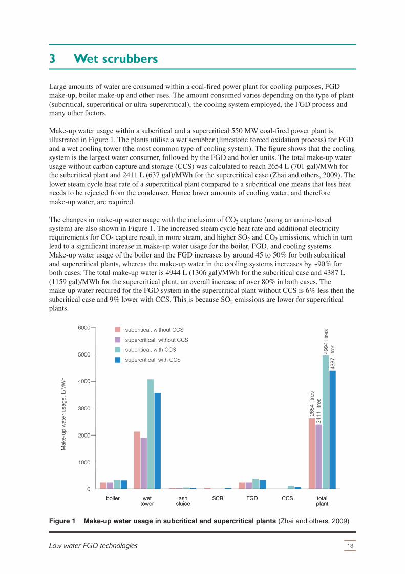
Make-up water usage within a subcritical and a supercritical 550 MW coal-fired power plant isillustrated in Figure 1. The plants utilise a wet scrubber (limestone forced oxidation process) for FGDand a wet cooling tower (the most common type of cooling system). The figure shows that the coolingsystem is the largest water consumer, followed by the FGD and boiler units. The total make-up waterusage without carbon capture and storage (CCS) was calculated to reach 2654 L (701 gal)/MWh forthe subcritical plant and 2411 L (637 gal)/MWh for the supercritical case (Zhai and others, 2009). Thelower steam cycle heat rate of a supercritical plant compared to a subcritical one means that less heatneeds to be rejected from the condenser. Hence lower amounts of cooling water, and thereforemake-up water, are required.
The changes in make-up water usage with the inclusion of CO2 capture (using an amine-basedsystem) are also shown in Figure 1. The increased steam cycle heat rate and additional electricityrequirements for CO2 capture result in more steam, and higher SO2 and CO2 emissions, which in turnlead to a significant increase in make-up water usage for the boiler, FGD, and cooling systems.Make-up water usage of the boiler and the FGD increases by around 45 to 50% for both subcriticaland supercritical plants, whereas the make-up water in the cooling systems increases by ~90% forboth cases. The total make-up water is 4944 L (1306 gal)/MWh for the subcritical case and 4387 L(1159 gal)/MWh for the supercritical plant, an overall increase of over 80% in both cases. Themake-up water required for the FGD system in the supercritical plant without CCS is 6% less then thesubcritical case and 9% lower with CCS. This is because SO2 emissions are lower for supercriticalplants.
supercritical, without CCSsubcritical, without CCS
boiler wettower
ashsluice
SCR FGD CCS totalplant
subcritical, with CCSsupercritical, with CCS
4994
litre
s
0
1000
2000
3000
4000
5000
6000
boiler wettower
ashsluice
SCR FGD CCS totalplant
Mak
e-up
wat
er u
sage
, L/M
Wh
4387
litre
s
2411
litre
s26
54 lit
res
Figure 1 Make-up water usage in subcritical and supercritical plants (Zhai and others, 2009)

Water consumption and losses for both subcritical and supercritical 500 MW coal-fired power plantswere evaluated by NETL in 2005 (Klett and others, 2005) and revised by the authors in 2007 (Klettand others, 2007). Both plants are equipped with limestone forced oxidation FGD systems, utilising alimestone slurry containing 70% water. Here, the cooling water system (wet tower) accounts fornearly 84% of the water loss in both subcritical and supercritical plants (see Table 1), with the waterloss in the flue gas and FGD system accounting for 16% of the total. If the water lost with the gypsumis excluded, then 15% of the water is lost through the flue gas in both plants. Over half the water thatends up in the flue gas is evaporated from just the FGD system. Water must be added to the system tomake up for these evaporative water losses, the amount added being a function of the unit size (fluegas flow) and sulphur feed rate. Wet scrubbers consume some 2160 L/min (571 gal/min) of make-upwater in a 500 MW subcritical plant and around 1900 L/min (502 gal/min) in a 500 MW supercriticalplant when burning 3 wt% S, dry basis, bituminous coal. The values differ from those in Figure 1since different assumptions are used in the models.
On a site which utilises dry/air cooling for the condenser, or where it is seawater cooled (once-throughcooling system), the use of water in wet FGD systems can easily be 40–70% of the total site usage(Couch, 2005). Only ~10% is used for boiler make-up water. This is because water withdrawal from alocal water body (such as a river, lake or the sea) and water consumption for the dry/air coolingsystem is minimal. Power plants equipped with once-through cooling systems have relatively highwater use but low water consumption as the cooling water is returned back to the local water sourcefrom which it was withdrawn. Wet cooling towers have relatively low water use but high waterconsumption compared with once-through systems since only make-up water (to replace evaporativewater losses and blowdown) is withdrawn. The cooling water is recycled in the system. Power plantswith a hybrid cooling system (which uses both air and water for cooling) will have a waterconsumption between those with a wet cooling tower or an air/dry cooling system.
14 IEA CLEAN COAL CENTRE
Wet scrubbers
Table 1 Water consumption and losses in power plants (data from Klett and others, 2007)
Subcritical power plant Supercritical power plant
L/min(gal/min)
L/MWh(gal/MWh)
L/min(gas/min)
L/MWh(gal/min)
Raw waterconsumption
21,800 (5759) 2514 (664) 19,400 (5125) 2249 (594)
Water to FGDsystem
2162 (571.1) 249 (65.8) 1899 (501.6) 220 (58.1)
Make-up water tocooling tower
19,495 (5150) 2247 (593.6) 17,371 (4589) 2013 (531.8)
Make-up water tocondenser
145 (38.2) 17 (4.4) 128 (33.9) 15 (3.9)
Water losses
Water with gypsum 307 (81) 35.2 (9.3) 269 (71) 31.4 (8.3)
Boiler flue gas 3,513 (928) 405 (107) 3096 (818) 360 (95)
Cooling towerblowdown
4,910 (1297) 566 (149.5) 4372 (1155) 506.5 (133.8)
Cooling towerevaporation
14,729 (3891) 1697.8 (448.5) 13,128 (3468) 1521.4 (401.9)
Total water losses 23,459 (6197) 2704 (714.3) 20,865 (5512) 2419.3 (639)

This chapter begins by describing limestone wet scrubbers before looking at methods designed tolower their water consumption, namely the reduction of evaporative water losses and recovering watervapour from the flue gas. The treatment of scrubber waste water to enable it to be recycled to the FGDsystem, thus lowering fresh water consumption, is outside the scope of the report.
3.1 Limestone wet scrubbers
The limestone FGD process is the most widely deployed technology for removing SO2 from flue gas.Although other sorbents, such as lime, magnesium oxide, ammonia and sodium carbonate, are used inwet scrubbers, limestone (calcium carbonate) is normally the cheapest sorbent and is available in largeamounts in many countries. As noted above, limestone wet scrubbers consume some 2160 L/min ofmake-up water in a 500 MW coal-fired subcritical plant (about 4.32 L/min per MW or 1.14 gal/minper MW) and around 1900 L/min in a 500 MW supercritical plant (about 3.8 L/min per MW or1 gal/min per MW) when burning bituminous coal (Klett and others, 2007). These figures, though, aredependent on a number of factors. Typical water consumption figures quoted by Adamson (2008) are5.7–6.8 L/min per MW (1.5–1.8 gal/min per MW). Wet scrubbers commonly remove 95–98% of theSO2, with the latest generation capable of removing 99%. They also remove hydrogen chloride (HCl),hydrogen fluoride (HF), and oxidised mercury (but not elemental mercury), and have been installedon units burning low to high sulphur coals.
A typical wet limestone FGD system consists of a limestone preparation, storage and handlingsystem, a FGD spray tower absorber, a by-product dewatering system, and a wastewater treatmentsystem. The absorber can be a co- or counter-current flow spray tower, with or without internalpacking or trays. The absorber unit is usually installed downstream of the particulate control device.In the USA, the flue gas enters the absorber at a temperature of around 120–180ºC (EPRI, 2007). Thetemperature depends on a number of factors relating to the boiler arrangements, coal type and the loadon the generator. European practice is to use a heat exchanger prior to the absorber, whereby the fluegas is cooled to around 80-90ºC. Passing through the scrubber, with all the evaporation taking place, itis further cooled to ~50ºC. The flue gas is then reheated in the heat exchanger (exchanging with theincoming gas) to ~90ºC before being emitted (Couch, 2005).
A common type of absorber is the counter-flow open spray tower (see Figure 2) where the limestoneslurry is pumped through banks of spray nozzles to atomise it into fine droplets and uniformly contactthe gas. The droplets absorb SO2 from the flue gas, facilitating reaction with the limestone. HCl
15Low water FDG technologies
Wet scrubbers
mist eliminators
flue gasfrom air heater
booster fan
limestone water
oxidation air to dewatering system
recyclepump
stackabsorbertower
reaction tank
ESP
Figure 2 Limestone wet scrubber system (Otter Tail Power, 2009)

present in the flue gas is also absorbed and reacts with the limestone to form calcium chloride. Someof the water in the spray droplets evaporates, cooling the gas and saturating it with water. Thedesulphurised flue gas passes through the mist eliminators to remove entrained droplets and is emittedto the atmosphere via the cooling tower, a wet stack or a dry stack after reheating. The spent sorbentslurry collects in the reaction tank at the bottom of the absorber. Compressed air is commonly injectedinto the reaction tank to oxidise the hydrated calcium sulphite into hydrated calcium sulphate(gypsum, CaSO4.2H2O). This oxidation step is termed forced oxidation. Complete oxidation isensured by maintaining a low pH. Limestone slurry is added to the reaction tank to control the pH andreplenish the limestone consumed in the process. A slurry recycle system recirculates the limestonesorbent from the reaction tank to the spray nozzles. A bleed system removes the appropriate amountof gypsum and solid wastes from the reaction tank to maintain process equilibrium, and transports thisslurry to the gypsum processing system. The gypsum is dewatered and processed to produce saleablequality product or is sent for landfill disposal. Water removed from the gypsum is returned to theprocess. A bleed stream is removed to control the chemistry of the scrubber liquor in the absorber, andthis wastewater has virtually no reuse potential within the power plant (Preston and others, 2011). Itcontains chlorides, heavy metals (including mercury) and other impurities and is treated in the watertreatment plant before it is discharged.
Limestone wet scrubbers have been in operation for over 30 y and, with their widespread application,is a well understood technology. They have a high SO2 removal efficiency (>98%), but do not capturesignificant amounts of SO3. If air pollution regulations require SO3 removal then it could be capturedby injecting an appropriate sorbent into the ductwork upstream of the wet scrubber (see Section 5.3.2)or, in the form of sulphuric acid, with a wet ESP located after the wet scrubber. Unfortunately, CO2 isproduced as a result of the reaction of limestone with SO2 (see Section 2.1.1) and is emitted with thescrubbed flue gas, thus adding to CO2 emissions from the power plant. The presence of sulphuric acidand other corrosive compounds means that the absorber vessel is manufactured from more expensivecorrosion-resistant materials. Similarly, corrosion-resistant materials are required in the downstreamequipment and ductwork due to the presence of corrosive chlorides and sulphuric acid in the flue gasexiting the mist eliminators. Otherwise the flue gas can be reheated to above its dew point to minimisecorrosion. The absorbers are also handling large volumes of abrasive slurries.
Parasitic power consumption is around 1.2–1.5% when burning low sulphur coals and 1.5–2% withhigh sulphur coals (Adamson, 2008). This is due to the additional ID fan power consumption tocompensate for the pressure drop across the absorber and the power requirements for the slurryrecirculation pumps. The gypsum dewatering equipment and wastewater treatment plant is relativelycomplex and expensive. The wastewater contains impurities originating from the coal, limestone andmake-up water, chloride salts and other FGD reaction products. If additives, such as dibasic acid, areintroduced to the limestone slurry to improve SO2 removal efficiency, then these could contaminatethe gypsum and wastewater. Several stages are required to treat the wastewater to meet dischargeregulations. The complexity and cost is likely to increase if future regulations mandate zero liquiddischarge in order to achieve a sufficient quality to enable its reuse in the power plant. The FGDwastewater is typically combined with other water discharges from the plant, such as that from thebottom ash handling system and cooling water, before it is treated. Capital and operating costs arerelatively high due to some of the factors discussed above. However, operating costs are often lowerthan the semi-dry scrubber processes (see Chapter 4) at the same SO2 removal level. The processproduces gypsum which can be sold to offset costs.
3.2 Reducing evaporative water losses
Cooling the flue gas from a typical ~140ºC to 90–100ºC prior to its entry to the wet scrubber reducesthe scrubber’s evaporative water losses. This can lower the water consumption in wet FGD systems by~40–50%. The flue gas exits the scrubber at a temperature of ~50ºC and is then reheated in plantswhere the cooling tower is used as the flue gas stack. This improves stack gas dispersion and helps
16 IEA CLEAN COAL CENTRE
Wet scrubbers

avoid condensation. Typically, the flue gas cooling system is incorporated with the flue gas reheatingsystem to form a regenerative heat recovery system. Otherwise, the extracted heat could be recoveredwithin the steam cycle, leading to an improvement in plant efficiency. The regenerative heat exchangeris installed either before or after the particulate control device, which is upstream of the wet scrubber.Heat exchangers for flue gas cooling are utilised in coal-fired power plants mainly in Japan andEurope.
As well as lowering the FGD water consumption, there are several other benefits from cooling the fluegas upstream of the wet scrubber (Nakayama and others, 2006; Rencher, 2008), including:� reduced gas volumes resulting in a smaller FGD system and stack requirements for new plants.
For retrofits, the reduced flue gas volume helps to offset the pressure drop associated with theheat exchanger;
� improved performance of ESPs and fabric filters due to reduced gas volume. Existing ESPsbenefit from a larger specific collection area and improved fly ash resistivity (resistivitydecreases when the flue gas is cooled). The greatest gain is likely to be from low sulphur coalswhich typically have higher resistivity ash. Fabric filters benefit from a decrease in theair-to-cloth ratio. These benefits translate into smaller particulate control devices for new plants;
� control of SO3 (sulphuric acid) emissions through condensation on the fly ash (when the heatexchanger is installed upstream of the hot-side particulate collector). SO3 emissions at the FGDoutlet were <0.1 ppm at Japanese power plants;
� improved mercury capture.
Disadvantages (Green, 2007) associated with regenerative heat exchangers include:� leakage of the unscrubbed gas into the scrubbed gas stream because the unscrubbed gas stream is
at a significantly higher pressure than the scrubbed gas stream. A 2% leakage rate has the impactof reducing the wet scrubber SO2 removal rate from 98% to 96%. Non-leakage heat exchangershave been developed and are commercially available;
� increased power consumption due to the pressure drop across the heat exchanger;� a corrosive environment due to sulphuric acid condensation. The use of corrosion resistant
materials will increase the cost of the heat exchanger. However, acid corrosion can be preventedby controlling the ratio of the particulate concentration to the sulphuric acid concentration. If ahigh enough concentration of particulates is present, then the sulphuric acid condenses onto theparticulates before it is condensed onto the surface of the heat exchanger (Nakayama and others,2006). Japanese power plants had no problems when the MHI heat exchanger was installedupstream of the hot-side ESP;
� fouling of the heat exchangers could potentially occur as the unscrubbed flue gas is cooled,increasing maintenance costs.
In addition, regenerative heat exchangers are expensive, and can have high operating and maintenancecosts.
3.3 Recovery of water vapour
A typical 400 MW coal-fired power plant equipped with a wet FGD unit requires about 30 m3/h(500 L/min) of demineralised make-up water for steam production, whilst emitting 150 m3/h(2500 L/min or 150 t/h) of water vapour through the stack (Daal, 2011; de Vos and others, 2008).Recovering 20% of the emitted water would enable a plant to become self-sufficient, but if over 20%is captured, then the plant would become a water supplier instead of a consumer. Flue gas contains8–11% of the water vapour in a power plant stack (Daal, 2011), although higher figures are quoted inthe literature. Thus capturing flue gas vapour could substantially lower the power plant’s waterconsumption. The captured water could be used as FGD make-up water, transported to the condenser,where it is added to the water steam cycle as additional water to compensate for the steam/waterlosses, or used elsewhere in the plant.
17Low water FDG technologies
Wet scrubbers
The moisture in boiler flue gas comes from three sources, namely fuel moisture, water vapour formedfrom the oxidation of fuel hydrogen, and water vapour carried into the boiler with the combustion air(Levy and others, 2011). Thus the amount of water vapour in flue gas is influenced by the coal type.Subbituminous coal, lignite and brown coal have a higher moisture content than higher rank coals andso contribute more moisture to the flue gas. Depending on the moisture and sulphur contents of thecoal, and the technology employed, then the water recovered could provide all the site water for a wetscrubber, for boiler water make-up and for other site uses. Water recovery offers not only thepossibility of zero water demand, but also zero liquid discharge.
There are three main ways of recovering water from flue gas:� condensing it out by cooling;� filter it out using a membrane; or� use a desiccant.
3.3.1 Condensing heat exchangers
Researchers at Lehigh University in the USA have conducted laboratory- and pilot-scale tests on theuse of condensing heat exchangers to recover water and heat from flue gas. One heat exchanger couldbe located between the ESP and FGD unit to capture the sensible heat, and additional heat exchangerscould be placed between the FGD unit and stack in order to both cool the flue gas (sensible heattransfer) and condense water vapour from the flue gas (latent heat transfer). The captured water can beutilised for power plant cooling or FGD make-up water, whilst the recovered heat could be used in theboiler or turbine cycle to improve boiler efficiency (Levy and others, 2008, 2011).
The pilot-scale tests involved extracting a slip stream after the wet scrubber in a high sulphurbituminous coal-fired power plant and passing it through four heat exchangers in turn. The heatexchangers operated in counterflow with cooling water passing through the tubes and the flue gasflowing outside the tubes. The available cooling water flow rate and temperature governs whether theheat exchangers are better suited for improving unit heat rate or recovering water vapour from fluegas. In the latter case, a likely source of cooling water is the cold boiler feedwater leaving the steamturbine condenser. The flow rate of this feedwater is typically about one half of the flue gas flow rateof the unit and, depending on the time of year and whether the unit uses once-through cooling or a wetcooling tower, the feedwater temperature ranges from about 30ºC to 43ºC. The colder the coolingwater, the greater the water condensation efficiency and the higher the rate of heat transfer. Both theseparameters also increase when the cooling water to flue gas flow rate increases. Water vapour captureefficiencies are limited to ~20% when cold boiler feedwater is the cooling fluid. With a cooling waterto flue gas flow rate ratio of 2, the condensation efficiency increased from 44 to 71% as the inletcooling water temperature decreased from 38ºC to 24ºC. Recovery of water vapour from flue gascould be enhanced through a combination of water- and air-cooled heat exchangers (Levy and others,2011).
Condensation efficiency is also influenced by coal type, which affects the initial moisture content ofthe flue gas, and the flue gas temperature. Figure 3 shows that water recovery from flue gas is moreefficient with high moisture coals, and at lower flue gas temperatures. Thus high moisture coals areprime candidates for water recovery from the flue gas. For low moisture coals, water recovery bycondensation may not be a practical option (Sarunac, 2010).
Condensing flue gas to recover water requires a large cooling capacity, can lead to corrosion andfouling of the heat exchanger, and causes a pressure drop, which is compensated with an ID fan. Thepresence of sulphuric, hydrochloric and nitric acids (from the flue gas) in the condensate water couldpotentially corrode the heat exchanger tubes. Inserting an acid trap before the first heat exchangerremoved 33% of the dissolved sulphate in its condensate water and 62–76% of the total sulphuric acidcaptured in the heat exchanger system in the pilot plant tests (Levy and others, 2011). Relatively low
18 IEA CLEAN COAL CENTRE
Wet scrubbers

cost corrosion resistant 304 SS alloy (or other corrosion resistant materials) could therefore be usedfor the heat exchanger tubes. Flue gas also contains fine gypsum (CaSO4) particles which couldpotentially foul the heat exchanger tubes. The highest calcium concentration was in the condensatewater from the first heat exchanger. Utilising an acid trap before the heat exchanger removed 60% ofthe calcium. However, the recovered water has to be treated before it can be recycled, and this can becostly.
A cost benefit analysis of a 600 MW power plant with one heat exchanger installed downstream of theFGD unit that captures 18% of the flue gas water vapour indicated that it would be cost effective. Thecapital cost of the heat exchanger is US$4.14 million, and its annual fixed and O&M costs would beUS$641,019. The latter figure includes the costs for the ID fan and feedwater pump. The capital andannual costs for the ion exchange system, needed to treat the condensate water to enable it to be usedin the power plant, are US$381,888 and US$152,127, respectively. The estimated benefit from theincreased power generation (18,974 MWh/y) and water savings is US$1.304 million versus totalannual costs of US$0.703 million (Levy and others, 2011). No dollar value was included for thereduced emissions of mercury and sulphuric, hydrochloric and nitric acids captured in the condensatewater. The availability of low temperature flue gas with reduced acid and water vapour content wouldalso lower the cost of capturing CO2 in amine and ammonia scrubbers.
3.3.2 Membranes
Researchers at the University of Twente, Netherlands, have developed a polymer-based compositehollow fibre membrane that is highly selective for water vapour at flue gas temperatures (Daal, 2011;de Vos and others, 2008). To start the process a vacuum is created inside the hollow fibre, causing apressure difference. A natural diffusion mechanism then begins, in order to re-establish the equaldistribution of the gas molecules inside and outside the tubes. Only the water molecules can passthrough the membranes, collecting on the inside of the tubes. The recovered water is of high qualityand mineral-free. It can be transported directly to the existing condenser system by applying a
19Low water FDG technologies
Wet scrubbers
0
10
30 35 40 45 50 552520Flue gas temperature, °C
Cond
ensa
tion
effic
ienc
y, wt
%
20
30
40
50
60
70
80
90bituminous coalwashed Illinois coalPRBlignite
Figure 3 Condensing efficiency as a function of flue gas temperature and coal type(Sarunac, 2010)
vacuum, where it is added to the water steam cycle as additional water to compensate for thesteam/water losses. Any non-condensables are expelled by the vacuum system. No waste water isproduced. The pressure drop that occurs over the membrane unit is compensated with an ID fan. Themajor energy input is electricity to run the vacuum pumps. The net electric efficiency can decrease by0.1–1.1 percentage points, depending on the heat exchanger lay-out and power plant characteristics(Daal and others, 2012). Combining the water capture membranes with CO2-selective membranescould lower CO2 emissions at the same time. The membranes modules are ideally placed after theFGD unit where the flue gas is saturated with water.
Tests in a coal-fired power plant and other industrial plants in the Netherlands and Germany haveindicated that at least 40% of the water in the flue gas can be recovered, turning the power plant froma water consumer into a water producer. The recovered water has a high enough quality that it can beemployed not only for demineralised water use in the power plant and by industry, but also for publicconsumption purposes.
An average cost for water from a conventional demineralisation plant in the Netherlands isaround�2 €/m3, and would be even higher in dry areas. An economic analysis of the membrane system,based on a membrane lifetime of 3 y and a water flux of 2 L/m2/h, quotes a cost of �1.24–1.38 €/m3 forthe recovered demineralised water, dependent on the configuration of the power plant (de Vos andothers, 2008). The price is based on existing power plants and so the price could be lower for newplants. In addition, further savings are possible since the calculations did not include the savings whenflue gas reheating is rendered obsolete. Reheating the flue gas to avoid condensation in the stackcould be omitted if enough water is removed from the flue gas. Calculations show that a coal-firedpower plant can increase its efficiency by about 1%, if reheating is no longer necessary (Daal, 2011).Energy requirements and savings when using membrane technology are further discussed by Daal andothers (2012).
The technology is being further developed under the European Union commissioned CapWa (capture
20 IEA CLEAN COAL CENTRE
Wet scrubbers
steamturbine
steam
flue gas
hot recovered water
recovered water
condensate
coolingwater in stack
coolingwater out
deaerator
high pressurewater heater
low pressurewater heater
economiser
air heater
condenser
flue gasdesulphurisation
flue gas
boiler
TMC/stage 1
TMC/stage 2
steambleed
Figure 4 Two-stage TMC integration with a power plant (NETL, 2009)

of evaporated water with novel membranes) project under the leadership of Kema in the Netherlands.Participants include companies from Europe, the Middle East and Africa, including those operating inarid areas. The aim is to develop a water capture module ready for industrial use in 2013-14. Themembrane modules will be demonstrated at the Ruthenberg coal-fired power plant in Israel, agas-fired power plant in Spain, and industrial plants elsewhere (Daal, 2011). More information aboutthis project can be found on the website www.watercapture.eu.
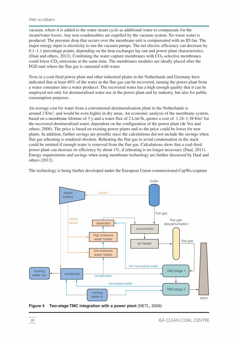
The Gas Technology Institute in the USA is also developing a membrane system to recover up to 90%of the water vapour from flue gas. It is based on their commercial, patented Transport MembraneCondenser (TMC) technology (a nanoporous ceramic membrane) that was originally developed forindustrial gas-fired boilers. Again, the recovered water is mineral-free and so can be used directly forboiler and/or FGD make-up water, and/or other uses, depending on the amount of water recovered. Atwo stage TMC system is being developed for coal-fired power plants that uses two separate coolingwater streams to maximise recovery of both the water and latent heat in the flue gas (see Figure 4).The inlet water for the first stage TMC unit is obtained from condensate from the steam turbinecondenser, whilst the second stage TMC inlet water is from part of the condenser cooling waterstream. The outlet water from the first TMC unit, with recovered water vapour and associated latentheat from the flue gas, passes to the deaerator for boiler water make-up. The second TMC unit’s outletwater and recovered flue gas water is returned to the cooling water stream. The TMC unit is placedbetween the FGD unit and stack (NETL, 2009; Wang, 2008; Wang and others, 2012). The system hasbeen tested on a slipstream from a coal-fired power plant in Baltimore, MD, USA.
3.3.3 Liquid desiccants
A liquid desiccant-based dehydration process has been developed, and tested at pilot-scale, by theUniversity of North Dakota’s Energy and Environmental Research Center in the USA that recovers50–70% of the water in the flue gas from a wet scrubber (Feeley and others, 2006; Folkedahl andothers, 2006). The technology is already used on a large scale for dehydration of air (air conditioningsystems) and natural gas conditioning.
The process involves cooling the flue gas before passing it through an absorption tower in which theliquid desiccant (such as calcium chloride, lithium bromide or triethylene glycol) is injected throughup to six spray levels. A packed bed configuration was also tested. The flue gas lean in water exits theabsorber, and is passed through a mist eliminator to remove any entrained desiccant droplets before itis discharged through the stack. The water-loaded desiccant is heated via a heat exchanger beforeentering the regenerator, as the hotter the desiccant the easier it is to separate the water. The watervapour is separated from the desiccant solution in a flash drum by differential pressure, and isrecovered in a downstream condenser. The regenerated hot desiccant solution is filtered to removeinsoluble contaminants, and is then cooled via a heat exchanger, before it is injected back into theabsorber. The colder the desiccant solution, the more water it can pick up. In subbituminous coal tests,and with a desiccant flow of 151–416 L/min (40–110 gal/min), about 0.3–0.9 L/min(0.08–0.23 gal/min) of water was recovered (Carney and others, 2008).
Low grade heating and cooling sources available in a power plant could be utilised to minimise thepower needs of the process. Depending on the amount of water to be removed from the flue gas, thesystem can be designed with no parasitic power consumption, other than pumping loads, by takingadvantage of the heat of absorption and the heat of vaporisation to provide the necessary temperaturechanges in the desiccant between the absorber and the regeneration tank (Folkedahl and others, 2006).Pilot-scale tests indicated that the presence of sulphur in the flue gas was not detrimental and that theprocess could actually lead to a further reduction in sulphur emissions (Copen and others, 2005). SO2capture is primarily influenced by the desiccant pH. The recovered water has a similar quality to thatfrom reverse osmosis treatment, which is normally used to produce boiler make-up water. It can beused for various plant needs as recovered or as direct cycle make-up after minimal treatment.
21Low water FDG technologies
Wet scrubbers

An economic analysis by Folkedahl and others (2006) for a 250 MWe coal-fired power plant treating aflue gas slipstream in the desiccant system (capacity 284 L/min (75 gal/min)) put the investment costs(equipment and installation) at US$5,837,762. Auxiliary power consumption would be ~1,051 kW.The total annual operating costs were estimated to be US$503,860. About 123 million litres(32.4 million gallons) of water would be produced per year, resulting in a price of 0.0053 US$/L(0.02 US$/gal or ~4.4 US$/m3) of pure water. Whether this is economically viable depends very muchon the location of the plant. The calculations were carried out for a power plant located in Wyoming,USA.
Questions remain as to the long-term interaction of the desiccant with the flue gas, contamination ofthe desiccant solution by flue gas constituents, and precipitates that may form and how to handlethem. Corrosion could be an issue with salt-based desiccants (such as calcium chloride), but can belargely mitigated through proper material selection. Glycol-based systems have the disadvantage ofatmospheric losses of glycol with the flue gas (Folkedahl and others, 2006). A combination ofcondensing heat exchangers with liquid desiccants is currently being investigated (Sarunac, 2010).
22 IEA CLEAN COAL CENTRE
Wet scrubbers

4 Dry scrubbers
23Low water FGD technologies
Semi-dry FGD processes are the second most common FGD system installed on coal-fired powerplants worldwide, with wet scrubbers being by far the predominant FGD technology. They typicallyconsume around 60% less water than wet scrubbers, but more water than the sorbent injectionprocesses.
The principal semi-dry processes in use today can be categorised as:� spray dry scrubbers;� duct spray dry process;� circulating dry scrubbers.
All of these systems typically utilise a calcium-based reagent (calcium hydroxide) which is introducedas a slurry (spray dry scrubbers, duct spray dry process) or as a dry powder (circulating dryscrubbers). They are normally installed after the air heater. After passing through the semi-dry FGDsystem, the fly ash, reaction products and unused sorbent are collected in a fabric filter or ESP. Theuse of fabric filters as the particulate collector offers an advantage over ESPs as absorption ofadditional SO2 and SO3 occurs in the dust filter cake. The humidity of the flue gas exiting the systemfavourably affects the performance of ESPs helping to counter the adverse effects of calcium-basedsorbents on fly ash resistivity (Ahman and others, 2002).
In Europe, the fly ash is often removed before the flue gas enters the FGD system, unlike mostinstallations in the USA. This enables the fly ash to be sold, and reduces the amount of waste fordisposal. In addition, it can reduce the lime sorbent consumption (for a given desulphurisation level),prevent erosion of downstream equipment, and can help to achieve greater ESP efficiency (EuropeanCommission, 2006). Fly ash pre-collection, though, increases capital and O&M costs.
4.1 Spray dry scrubbers
Spray dry scrubbers (SDSs), also called spray dry absorbers, were developed in the late 1970s. Todaythere is around 40,000 MW of capacity worldwide equipped with SDSs, the majority of which (about95 units) are installed in the USA (Jones and Weilert, 2011). They are most often used on small- tomedium-sized (~450 MW) units burning low to medium sulphur (2% S) coals (Moss, 2010). SO2removal efficiencies are typically in the range 90–95%, depending on the sulphur content of coal.Lower SO2 removal rates are attained when combusting high sulphur coals. Ca:S stoichiometric ratiosfor a 0.6% sulphur subbituminous coal, 1.3% sulphur bituminous coal and 2% sulphur bituminouscoal are typically 1.2, 1.4 and 1.6, respectively, for a 95% SO2 removal efficiency (Sargent and Lundy,2007). SO3 removal efficiencies are ~99% (Moss, 2010), and over 95% of HCl, HF and oxidisedmercury are removed when fabric filters are installed (Babcock & Wilcox, 2009; Tavoulareas andJozewicz, 2005).
In the SDS process (see Figure 5), a concentrated lime slurry (a few systems use a sodium carbonatesolution) is introduced into the top of the absorber vessel through rotary atomisers or dual fuelnozzles. These atomise the slurry creating a fine mist of droplets containing the reagent, which reactswith SO2 and SO3 in the downward flowing flue gas to form calcium sulphite and sulphate (seeSection 2.1.1). Simultaneous cooling of the flue gas from 150ºC or higher to as low as 17ºC above theadiabatic water saturation temperature occurs (EPRI, 2007). The residence time of the gas in thescrubber is ~12–15 s. Part of the dry waste products is collected in the bottom of the scrubber and therest from the flue gas as it passes through the particulate collector. A portion of these solids istypically mixed with wastewater and recycled back to the scrubber to improve sorbent utilisation, aswell as promoting droplet drying in the SDS vessel. If the fly ash is not removed from the flue gas

before it enters the absorber, then recyclingalkaline fly ash in the products (such as fly ashproduced from subbituminous coal andlignite) will remove additional SO2 and SO3.
Some scrubber designs utilising rotaryatomisers introduce the flue gas through acentral roof gas disperser, whilst another(Alstom) incorporates three roof mounted gasdispersers for use on units up to a 450 MWcapacity (Buschmann, 2008). For large utilityboilers (450 MW), the GEA Niro SDSintroduces the flue gas through two locations,a roof mounted gas disperser and a central gasdisperser. The gas dispersers are designed todistribute the flue gas evenly around theatomiser(s) units at the required velocity tomaximise contact between the flue gas anddroplets. Scrubbers with dual fuel nozzlesintroduce the flue gas through an array ofthese nozzles installed on the roof. Carefulcontrol of the gas distribution, slurry flow rate
and droplet size ensure that the droplets fully evaporate before contacting the internal walls of thescrubber. The water must evaporate sufficiently to avoid formation of undesirable deposits andcorrosion problems.
Modern SDSs utilise a lime sorbent (hydrated or quick lime) since it is more reactive than limestoneand is less expensive than sodium-based reagents. The hydrated lime is mixed with excess wateron-site or the quick lime is slaked to produce a calcium hydroxide slurry containing ~20–25 wt%solids. The recycle solids are separately mixed with water to produce a slurry containing up to 45 wt%suspended solids (EPRI, 2007). Slaking quick lime requires relatively high quality water, whereaslower quality wastewater can be used when slurrying the recycle solids. The recycle slurry may bemixed with the fresh lime slurry before or during injection, or may be injected separately. Althoughrecycling reduces the reagent cost, it increases capital and O&M costs.
SO2 removal efficiency is influenced by the coal sulphur content (SO2 inlet concentration), inlettemperature, flue gas humidity, slurry droplet size and other factors. The rate at which the reagentslurry is fed to the atomiser directly influences the rate of SO2 removal. Also, the amount of slurrythat can be added is dependent on the amount of water that can be utilised. No more slurry can beinjected when sufficient water has been added to cool the flue gas to the safe margin above thesaturation temperature. This linkage between the rate of reagent slurry feed and the rate of water feedeffectively limits the maximum rate at which reagent can be fed to the SO2 scrubber. Thus the rate atwhich SO2 can be removed is correspondingly limited (Jones and Weilert, 2011). Since most of theSO2 capture occurs when the sorbent is still moist, adding deliquescent salts, such as chlorides, canimprove SO2 removal efficiency by extending the time in which the sorbent remains moist. A similareffect is achieved when coals with elevated chloride content are used (Srivastava and Jozewicz, 2001).Chlorine in the flue gas reacts with the calcium sorbent to form calcium chloride which is adeliquescent salt. However, the salts can form unwanted deposits on the scrubber walls anddownstream equipment. Therefore the addition of deliquescent salts must be carefully controlled.
SDSs are considered to be efficient and reliable. Water consumption is ~20–40 L/1000 m3 of flue gas(European Commission, 2006) or ~0.14 L/kWh (Singleton, 2010), due primarily to the preparation ofthe hydrated lime slurry. Water usage is a function of the temperature of the flue gas and its flow rate.Power consumption of SDSs is ~0.5–1% of the electric capacity of the power plant compared to
24 IEA CLEAN COAL CENTRE
Dry scrubbers
particulatecontroldevice
stack
solids recyclingor disposal
spraydryer
solids recyclingor disposal
lime slurry
flue gas
Figure 5 Spray dry scrubber system

1–1.5% for wet scrubbers (European Commission, 2006). Installing a SDS to remove 90% of the SO2at the Big Stone Unit 1, in South Dakota, USA, would consume 3325 kW or 0.7% of nominalgeneration compared to 9500 kW or 2% of nominal generation for a wet scrubber removing 95% SO2(Otter Tail Power, 2009). SDSs can typically operate at loads of ranging from ~25% to 100% (Jonesand Weilert, 2011), although some manufacturers have claimed a turndown to 10% load (Buschmann,2008). The ability of SDSs to operate at lower loads is dependent on the flue gas temperature enteringthe scrubber. No reagent can be fed unless the flue gas is hot enough to dry the slurry droplets to apowder before the flue gas exits the scrubber. This therefore hampers the ability of SDSs to controlemissions at low loads and prolongs the time during start-up before SO2 removal can begin. Thereagent feed system can rapidly change the amount of sorbent being fed into the scrubber and so canrespond to load changes, once the system is operating (Jones and Weilert, 2011).
A SDS is cheaper to install than a wet scrubber for small- to medium-size units (European Commission,2006), but its capital cost advantage may not apply for large power plants when multiple SDS units arerequired. The capital cost for retrofitting a SDS system on the Big Stone Unit 1 (475 MW net) wasestimated to be US$141,300,000 (US$ year 2009), or a unit cost of 297 US$/kW, compared toUS$171,800,000 or 362 US$/kW for a wet scrubber (Otter Tail Power, 2009). The costs were calculatedfor a 90% removal efficiency for the SDS compared to 95% for the wet scrubbers. But SDSs aregenerally more expensive to operate than wet scrubbers due to their slightly lower sorbent utilisation(when achieving comparable SO2 removal), higher sorbent costs and the costs of waste disposal.Possible applications of the waste products are covered in Section 2.3. SDSs cost about the same toinstall as circulating dry scrubbers (Jones and Weilert, 2011), but their O&M costs can be higher due tothe wear and erosion of the slurry atomisers and of the equipment used in the preparation, handling andtransport of the slurries (Buecker and Hovey, 2011). SDSs with fabric filters can capture more SO3, HCl,HF and mercury than wet scrubbers, and with their smaller footprint, are usually preferable for retrofit.
4.2 Duct spray dry process
The duct spray dry process is essentially the same as the SDS process except that the lime slurry issprayed directly into the ductwork upstream of the particulate control device. There is no separateabsorber vessel. The ductwork should be capable of providing a residence time of 1 to 2 s to allow themoisture in the slurry to evaporate for the SO2 removal reactions to occur and prevent undesirabledeposits forming on the ductwork. In addition, the duct must not contain any flow obstructions(Srivastava and Jozewicz, 2001).
The process was developed primarily for retrofitting to existing power plants where a moderate degreeof SO2 removal (50–75%) is required and where plant operating hours and remaining lifetime arelimited (DTI, 2000). Capital costs will be low since no separate absorber vessel is needed, and noprocess wastewater is produced. Drawbacks include the potential abrasion from the slurry, corrosionof the duct, and a low sorbent utilisation rate, as well as its relatively low SO2 removal efficiency. SO2removal efficiency is lower than the SDS, circulating dry scrubber and wet scrubber systems, butgenerally slightly higher than the injection of a dry lime sorbent in DSI systems (see Section 5.3.1).Recycling the solid by-products can improve sorbent utilisation. Specialised processes and additivesto improve the performance of the lime slurry sorbents have been developed.
Some power plants are injecting sodium-based sorbent solutions to capture SO3 in what is essentiallya duct spray dry process. This is discussed in Section 5.3.2, along with other dry and wet sorbents forSO3 removal. The sorbents are discussed together so that they can be more easily compared.
4.3 Circulating dry scrubbers
The circulating dry scrubber (CDS) technology was first developed in Germany in the 1980s. Today,
25Low water FDG technologies
Dry scrubbers

the total capacity of utility units worldwide using this technology is ~15,000 MW (Jones and Weilert,2011), with units in Europe, Asia (particularly China), and the USA. Like SDSs, a CDS typicallyconsumes around 60% less water than wet FGD processes (Bostick and Moss, 2011). It is fitted afterthe air heater and may follow a particulate collector which captures the fly ash. Unlike SDSs, a CDSnormally utilises dry hydrated lime as the primary reactant in an upflow reactor in which the reactantsare introduced through the bottom of the absorber. Ca(OH)2 reacts with SO2 to produce calciumsulphite. Some of the calcium sulphite then reacts with oxygen in the flue gas to produce calciumsulphate (see Section 2.1.1). The sulphite and sulphate compounds, along with the fly ash, if it is notpre-collected, and unreacted sorbent are removed by the particulate collector and continuouslyrecycled via air slides to the scrubber to maximise sorbent utilisation. The fly ash contains a smallamount of CaO which converts to Ca(OH)2, increasing the reactant quantity. A small portion of thereaction by-products are removed to keep a constant inventory of solids in the system.
Dry fresh sorbent and water can either be added to the recycled solids or injected separately into thescrubber. Adding lime and water separately means that the lime feed can be easily adjusted to handlevariable SO2 concentrations during start-up, from load changes or if flexibility is needed in fuelselection. This differs from a SDS, which cannot feed any reagent unless the flue gas is hot enough todry the slurry droplets to a powder before the flue gas exits the spray dryer. In CDS systems, theinjection water does not have to be of high quality since it evaporates during the process (Buecker andHovey, 2011). Utilising low quality water, such as cooling tower blowdown or a wet FGD purge,could potentially lower the amount of wastewater to be treated and reduce water pollution from thepower plant. Just enough water is introduced into the gas stream to lower its temperature to theoptimum level for the reactions to occur, but no more than can be fully evaporated; over wetting theparticles can cause scaling problems in the reactor. Therefore no wastewater is generated. Theby-products are dry and so are easily handled. They can be disposed of in a landfill or potentially usedin construction, mine backfilling, landscaping or other applications (see Section 2.3). The reactions toremove sulphur can either take place in a fluidised bed (circulating fluidised bed scrubbers and gassuspension absorbers) or in an entrainment process (NID™).
The Enhanced All-Dry (EAD™) Scrubber, developed by Procedair (now Solios Environnement) in the1980s, is a circulating entrained process. The flue gas and dry hydrated lime reagent enter the bottomof the vertical venturi tower and pass upwards into the reaction zone before the flue gas is internallyredirected back downwards. The flue gas exits the tower and passes to the particulate collector. Theprocess has been installed on industrial plants, but has not yet been installed on coal-fired powerplants. In March 2012, Hitachi Power Systems America signed a licence agreement with SoliosEnvironnement to design and supply the technology to the global electric utility market.
4.3.1 Circulating fluidised bed scrubbers
Circulating fluidised bed (CFB) scrubbers (also termed circulating dry scrubbers) are in operation onfacilities ranging in size from less than 10 MW to 350 MW. Multiple units are required for plants witha higher capacity, although some manufacturers claim that a single absorber can now be configuredfor 750 MW plants (Moss, 2010). China has some of the largest CFB units capable of capturing morethan 90% of SO2 when burning up to 3% sulphur coals (Sargent and Lundy, 2007). CFB scrubbershave been installed on Chinese coal-fired power plants up to 660 MW in size (Jiang and others, 2011).The largest CFB unit in the USA is at the 420 MW (385 MW net) Dry Fork station near Gillette, WY,burning PRB coal. The plant started commercial operation in Nov 2011, and uses a Graf-Wulff (nowpart of Foster Wheeler) reflux CFB scrubber, which was designed to reduce SO2 by 95% down to0.0258 kg/GJ (0.06 lb/million Btu) (Bostick and Moss, 2011). Performance testing achieved removalrates of >98% for SO2, and >99% for SO3 and HCl (Graf-Wulff, 2011). The Ca:S stoichiometric ratiois not given. Typical stoichiometric ratios of 1.5, 1.8 and 2 are required for 98% SO2 removal whenburning subbituminous (0.6% sulphur), low sulphur (1.3%) bituminous and medium sulphur (2%)bituminous coals, respectively (Sargent and Lundy, 2007). CFB systems have been successfully
26 IEA CLEAN COAL CENTRE
Dry scrubbers

installed at plants firing high sulphur (3.5%) coals (Moss, 2010). SO2 removal efficiencies as high as99% (depending on inlet SO2 loading) can be achieved, if high reagent consumption can be tolerated.
A flow diagram of the CFB system at the Dry Fork station is given in Figure 6. The flue gas enters theCFB reactor at the bottom and flows upwards through a bank of venturis. These increase the velocityof the flue gas before it mixes with the hydrated lime and recycled solids to create the characteristicfluidised bed. In some designs, such as the Graf-Wulff and Turbosorp®, the fresh sorbent andrecycled solids are injected above the venturis, whereas the Lurgi Lentjes (now Doosan Lentjes)design introduces them below the venturis. Water is injected into the fluidised bed to both humidifyand cool the flue gas to ~70ºC or about 20–25ºC above its adiabatic saturation temperature. The wateris rapidly dispersed over the surface of the particles in the bed, forming a thin layer of liquid on eachparticle. The SO2, SO3 and other acid gases are absorbed into the liquid layer and react with theCa(OH)2.
The fluidised bed recirculates the reactive material within the reactor to achieve a high retention time.An additional benefit is the continuous abrasion of the sorbent particles, resulting in the exposure offresh reactive surfaces. The flue gas takes ~5 s to pass through a 23 m deep fluidised bed (Moss,2010). At low boiler loads, when the flue gas flow is low, some of the cleaned flue gas is returned tothe CFB reactor in order to maintain sufficient velocity through the venturis to sustain the fluidisedbed.
A multi-stage humidification system has been developed by Zhejiang University’s Institute forThermal Power Engineering whereby the water is injected in two stages, with one level of waternozzles above the venturis and a second level further up the reactor. This distributes the water moreevenly throughout the reaction zone, and the time that the humidity content is above the criticalmoisture point is extended. SO2 removal efficiency increased by over 1%, whilst the total waterconsumed was the same as that consumed in single stage humidification (Gao and others, 2010).
Sorbents that can be utilised without the need for flue gas humidification are being investigated atTsinghua University in China. The sorbents are prepared by rapidly hydrating lime (CaO) with coalfly ash, CFB boiler ash or boiler ash. The product is then dried and crushed. The prepared sorbentconsists of fine calcium-containing particles adhering to the surface of the larger ash particles.
27Low water FDG technologies
Dry scrubbers
boiler
SCR airheater
limestack
limesilo
limehydration
hydratedlime bin
productsilo
hopper
fabric filter
CFBabsorber
water injection
water
waterstorage
Figure 6 CFB scrubber flowsheet for Dry Fork station (Bostick and Moss, 2011)

Desulphurisation efficiencies of 67–83% were achieved in a pilot-scale CFB-FGD system at a Ca:Sratio of 2 and bed temperatures of 600–800ºC. The desulphurisation efficiency was increased to 95%at a bed temperature of 750ºC and Ca:S ratio of 1.5 by reusing the spent sorbent. The amount ofCaSO4 in the by-product means it could be used to treat alkali soils (Li and others, 2010a,b, 2011;Matsushima and others, 2004; Zhang and others, 2006).
CFB scrubbers do not normally suffer from scaling, plugging or corrosion problems (DTI, 2000).They have good turndown capability and can accommodate rapid changes in fuel sulphur content.Their energy consumption is typically ~0.3–1% of the electric capacity of the plant (EuropeanCommission, 2006), largely from the booster ID fans needed because of the pressure drop caused bythe reactor. They consume around 60% less water than wet FGD processes. Water consumption at theSiekierki heating plant in Poland, fitted with a Turbosorp® scrubber, was contracted to be 125 L/minand energy consumption to be less than 750 kWh/h, with a SO2 inlet concentration of 437–1260 ppmvdry (SO2 outlet concentration �175 ppmv, 6% O2). The plant consumed 117 L/min of water and520 kWh/h during the performance test when the SO2 inlet concentration was 770 ppmv dry (SO2outlet concentration 157 ppmv, 6% O2); the Ca:S ratio was 1.1 (Licata and others, 2004). A 205 MWeplant would consume 833 L/min (220 gal/min) of water when removing 98+% of the SO2 (inlet SO2concentration is 1400 ppm or 1.38 kg/GJ (3.2 lb/million Btu)). It would consume ~2% of the power,and maintenance would cost 15 US$/kW (Chenevey and Smith, 2011).
CFB scrubbers are easy to maintain as they do not require high maintenance mechanical equipmentsuch as grinding mills and abrasion resistant slurry pumps (European Commission, 2006), and theygenerate no wastewater. As a result, CFB scrubbers have lower capital and maintenance costs andrequire a smaller footprint than wet limestone scrubbers. In addition, removal rates for SO3, HCl andHF are greater in CFB scrubbers, and ~95% of mercury can be removed (Ake and Licata, 2011).However, they are more expensive to operate than wet limestone scrubbers due to their consumptionof a more expensive reagent and they generate solid wastes that have little marketable value.
4.3.2 Gas suspension absorption process
The Gas Suspension Absorption (GSA) process was developed in Denmark by FLS Miljø (FLSmidth)and has been in commercial use since the 1980s in the power generation, waste-to-energy (municipalincinerators), iron and steel, and cement industries. A GSA system was recently installed at the PointComfort power plant, TX, USA. The technology is typically applied to small- to medium-sized boilersburning low to high sulphur coals. SO2 removal efficiencies of over 98% have been achieved,approaching those of wet scrubbers. Over 99% of the HCl and HF, and ~88% of the mercury isremoved (Pittsburgh Energy Technology Center, 1996). Most of the SO3 is also captured.
The GSA process is similar to CFB scrubbers but has an integral cyclone for recirculating the solidsvia a recirculation box to the fluidised bed reactor (see Figure 7). The flue gas enters the bottom of thereactor and passes through the venturi. A lime sorbent and cooling water mixture is injected via asingle dual fluid nozzle installed on the venturi. The sorbent can be quick lime (which is first slaked toproduce a 20% solid slurry) or dry hydrated lime (FLSmidth, 2010). Rapid evaporative cooling occurswithin the fluidised bed. Around 99% of the solids (fly ash, lime and reaction products) in the flue gasexiting the reactor are captured in the cyclone and introduced back into the reactor just above theventuri. Small particles exiting the cyclone are collected in an ESP or fabric filter. The residence timeof the flue gas in the reactor and cyclone is around 3 to 5 s (Głomba and Mazurek, 2008).
Like CFB scrubbers, the GSA system does not normally suffer from scaling, plugging or corrosionproblems, and it produces no wastewater. Water consumption at the 165 MW Skawina power plant inPoland is 14.2 m3/h (237 L/min) when treating 615,000 m3/h of wet flue gas. SO2 removal efficiencywas over 92% at a reactor inlet SO2 concentration of 3600 m3 on dry flue gas (Głomba and Mazurek,2008). Lime consumption is relatively low compared with other dry and semi-dry FGD processes. The
28 IEA CLEAN COAL CENTRE
Dry scrubbers

Ca:S ratio was 1.4 when 96% of the SO2 was captured in a demonstration of GSA coupled with apulse jet fabric filter. A 2.6% sulphur bituminous coal was combusted, and lime utilisation was ~70%.A lower SO2 efficiency (90%) was achieved with an ESP. In this case the Ca:S ratio was 1.3 and limeutilisation was ~66%. The demonstration was carried out in the USA by the Tennessee ValleyAuthority on a 10 MWe slipstream in the 1990s (AirPol Inc, 1999; Pittsburgh Energy TechnologyCenter, 1996). The GSA system is cheaper to install than wet scrubbers, but its operating costs will behigher due to the more expensive reagent. Pre-collecting the particulates in a cyclone reduces theparticulate loading from the GSA system by 3–5 times compared to a SDS. The lower particulateloading, along with its small footprint, makes the GSA system especially suited for retrofit into an airpollution control system with an existing particulate collector. Like the other semi-dry processes, thedry by-products have little marketable value.
4.3.3 NID™ system
Alstom’s Novel Integrated Desulphurisation (NID™) technology (also known as Flash DryerAbsorber) has been around for more than 20 years. There are over 100 installations coveringapplications in the power generation, iron and steel, and waste-to-energy industries (Alstom, 2008),including about 60 coal-fired power plants in Europe, Asia and the USA. This number is increasing asseveral electric utilities in the USA have recently announced plans to install NID™ systems. Thetechnology is generally limited to low to medium sulphur coals, where SO2 removal efficiencies of upto 95% are required (EPRI, 2007). Nevertheless, improvements have increased this figure to 98%,nearer the efficiency achieved by wet FGD systems. The NID™ installation at the 630 MW BraytonPoint 3 power plant in Somerset, MA, USA, with a SO2 inlet loading of 1.1 kg/GJ (2.5 lb/millionBtu), is being designed to reduce SO2 emissions by 98%. The Ca:S stoichiometric ratio is 1.5 to 1.8(FGD & DeNOx Newsletter, 2012). NID™ systems also remove SO3, HCl, HF, and trace metals. SO3removal levels can reach less than 1 ppm (Alstom, 2012) and ~91% of mercury can be captured (Wuand others, 2008).
29Low water FDG technologies
Dry scrubbers
activatedcarbon
silo
watertank
recirculation box
nozzle lance
aircompressor
limeslurry
limesilo
water inlet
flue gas
flue gas
flue gas
stackrecirculated sorbent
by-product
particulate control device
reactor cyclone
Figure 7 GSA process flowsheet (FLSmidth, 2010)

Combining NID™ with CFB bed boilers optimises desulphurisation when combusting high sulphurcoals, and reduces reagent consumption. Limestone is injected into the boiler for SO2 control. Theunreacted lime (CaO) remaining in the fluidised bed boiler outlet flue gas helps remove SO2 in theNID™ reactor. For this application, the downstream particulate collectors are specifically designed tohandle the very high circulating particulate loads (EPRI, 2007).
The unique feature of NID™ technology is its J-shaped duct reactor, which has a square cross section,and is integrated with a pulse jet fabric filter or, less commonly, an ESP. Hydrated lime, quick lime oralkaline ashes can be used as the reagent. Fresh reagent and the fly ash, reaction products andunreacted solids collected from the particulate collector are humidified in the mixer/humidifier by theaddition of water (see Figure 8). When quick lime is used as the reagent it is dry slaked to Ca(OH)2(Alstom, 2008). The humidified Ca(OH)2 mixture is then injected near the bottom of the NID™absorber into the upward flowing flue gas. With the high solids-to-water ratio, evaporation occursrapidly, cooling and humidifying the flue gas, whilst flash drying the particulates. No water is sprayedinto the absorber as is the case in CFB scrubbers. The SO2 reactions and drying times within theabsorber take less than 2 s. The cooled flue gas then flows to the particulate collector, where theparticles in the flue gas are removed and recycled back through the NID™ system, and the cleanedgas is emitted through the stack.
The fast reaction time in the absorber is possible due to one of the outcomes from the reactionbetween quick lime and water that generates hydrated lime. The physical and chemical properties ofthe CaO-water reaction reduce the particle size from over 800 µm to less than 10 µm. The largesurface area created enables the reaction with SO2 to proceed effectively within a short residence time(Buecker and Hovey, 2011).
Water consumption is about the same as for a lime spray dryer and CFB reactor. No wastewater isgenerated, and low quality water, such as cooling tower blowdown or a wet FGD purge, can be used inthe humidifier/mixer (Alstom, 2008, 2012). One feature of NID™ is its modular design, where eachmodule can handle the equivalent of ~75 MW of flue gas. There is no upper limit on the number ofmodules that can be combined and so it can be installed on large power plants (Morris, 2010). Anadvantage with the modular design is its flexibility regarding unit downturn. A turndown of up to 50%
30 IEA CLEAN COAL CENTRE
Dry scrubbers
stack
ESP or fabric filter
CaO humidifiermixer
endproduct
boiler
fuel
water
Figure 8 NID™ process flow diagram (EPRI, 2007)

per module with no flue gas recirculation is possible for low load operation. The small footprint of aNID™ module (<20% of a comparable spray dryer or CFB scrubber) makes it suitable for retrofitapplications where space is limited. Capital investment costs are low.
4.4 Comments
The SDS and CDS semi-dry systems have a number of advantages over wet limestone scrubbers(Moss, 2010; Sargent and Lundy, 2007) including:� the consumption of ~60% less water (but they consume more water than dry FGD systems);� production of no wastewater as basically all the water added to the scrubber is evaporated.
Therefore no wastewater treatment system is required;� the waste products are dry and therefore easily handled;� the scrubbers can be constructed of unlined low carbon steel as opposed to more expensive lined
carbon steel or alloys used for wet scrubbers;� smaller space requirement, and so may be easier for retrofit applications;� lower auxiliary power consumption;� more efficient capture of SO3, HCl and other acid gases, and mercury;� lower investment cost.
The main disadvantages of SDS and CDS systems when compared to wet scrubbers are:� lower SO2 removal efficiency although modern CDS systems can remove over 98% of SO2,
approaching the levels reached by wet scrubbers;� multiple absorber vessels are typically required for units with a capacity higher than ~400 MW;� no saleable by-product. The waste product has fewer uses than the saleable gypsum produced in
wet scrubbing processes (see Section 2.3);� higher operating costs mainly due to their higher reagent costs;� maintenance costs of fabric filters in CDS systems can be higher than those for wet FGD units due
to their greater wear. Higher particulate loading in the fabric filter from the recycling ofby-products in CDS systems means more frequent cleaning and hence greater wear.
The characteristic features of SDS and CDS systems are given in Table 2. The SO2 and SO3 removalrates shown in the table are typical rates and will be site specific since they are partly dependent onthe coal sulphur content. SDS systems are usually used at power plants burning low to medium (2%)coals, capturing up to 95% of the SO2 (Moss, 2010). SDS technology is typically characterised asbeing limited to coals with sulphur contents below the equivalent of 1.29 kg SO2/GJ (3 lbs ofSO2/million Btu). CDS technology is applicable to coals having a wider range of sulphur content, withover 98% of the SO2 removed when firing high sulphur (3.5%) coals. Guarantees of 98% have beenprovided for coals with sulphur content (expressed as SO2 emission potential) up to 3.1 kg SO2/GJ(7.2 lb SO2/million Btu) (Jones and Weilert, 2011). Both technologies remove over 95% of the HCl,HF and other acid gases, and nearly 99% of the SO3.
A CDS normally utilises dry hydrated lime as the primary reactant in an upflow reactor in which thereactants are introduced at the bottom of the scrubber. This differs from a SDS which utilises a slurryreagent and the flue gas flows vertically downwards through the reactor. Since lime and water areadded separately in a CDS, the lime feed can be easily adjusted to handle variable SO2 concentrationsduring start-up, from load changes or if flexibility is needed in fuel selection. It differs from a SDS,which cannot feed any reagent unless the flue gas is hot enough to dry the slurry droplets to a powderbefore the flue gas exits the spray dryer. This hampers the ability of SDS technology to controlemissions at low loads and prolongs the time during start-up before SO2 removal can begin (Jones andWeilert, 2011). However, SDS has a more efficient turndown (Chenevey and Smith, 2011).
The injection water in CDS systems does not have to be of a high quality. Low quality process watercould be used. On the other hand, high quality water is required if quick lime is slaked on-site for use
31Low water FDG technologies
Dry scrubbers
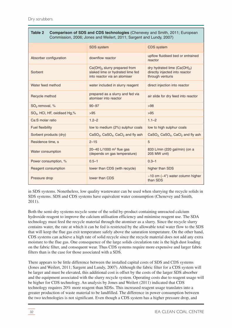
in SDS systems. Nonetheless, low quality wastewater can be used when slurrying the recycle solids inSDS systems. SDS and CDS systems have equivalent water consumption (Chenevey and Smith,2011).
Both the semi-dry systems recycle some of the solid by-product containing unreacted calciumhydroxide reagent to improve the calcium utilisation efficiency and minimise reagent use. The SDAtechnology must feed the recycle material through the atomiser as a slurry. Since the recycle slurrycontains water, the rate at which it can be fed is restricted by the allowable total water flow to the SDSthat will keep the flue gas exit temperature safely above the saturation temperature. On the other hand,CDS systems can achieve a high rate of solid recycle since the recycle material does not add any extramoisture to the flue gas. One consequence of the large solids circulation rate is the high dust loadingon the fabric filter, and consequent wear. Thus CDS systems require more expensive and larger fabricfilters than is the case for those associated with a SDS.
There appears to be little difference between the installed capital costs of SDS and CDS systems(Jones and Weilert, 2011; Sargent and Lundy, 2007). Although the fabric filter for a CDS system willbe larger and must be elevated, this additional cost is offset by the costs of the larger SDS absorberand the equipment associated with the slurry recycle system. Operating costs due to reagent usage willbe higher for CDS technology. An analysis by Jones and Weilert (2011) indicated that CDStechnology requires 20% more reagent than SDSs. This increased reagent usage translates into agreater production of waste material to be landfilled. The difference in power consumption betweenthe two technologies is not significant. Even though a CDS system has a higher pressure drop, and
32 IEA CLEAN COAL CENTRE
Dry scrubbers
Table 2 Comparison of SDS and CDS technologies (Chenevey and Smith, 2011; EuropeanCommission, 2006; Jones and Weilert, 2011; Sargent and Lundy, 2007)
SDS system CDS system
Absorber configuration downflow reactorupflow fluidised bed or entrainedreactor
SorbentCa(OH)2 slurry prepared fromslaked lime or hydrated lime fedinto reactor via an atomiser
dry hydrated lime (Ca(OH)2)directly injected into reactorthrough venturis
Water feed method water included in slurry reagent direct injection into reactor
Recycle methodprepared as a slurry and fed viaatomiser into reactor
air slide for dry feed into reactor
SO2 removal, % 90–97 >98
SO3, HCl, HF, oxidised Hg,% >95 >95
Ca:S molar ratio 1.2–2 1.1–2
Fuel flexibility low to medium (2%) sulphur coals low to high sulphur coals
Sorbent products (dry) CaSO3, CaSO4, CaCl2 and fly ash CaSO3, CaSO4, CaCl2 and fly ash
Residence time, s 2–15 5
Water consumption20–40 L/1000 m3 flue gas(depends on gas temperature)
833 L/min (220 gal/min) (on a205 MW unit)
Power consumption, % 0.5–1 0.3–1
Reagent consumption lower than CDS (with recycle) higher than SDS
Pressure drop lower than CDS~10 cm (~4") water column higherthan SDS

hence higher fan power, this is offset by its lack of large atomiser drive motors and auxiliaryequipment. The CDS technology generally requires a smaller number of motors than the SDStechnology. An electric utility in the USA that is operating CFB scrubbers alongside units with SDSshave reported lower O&M costs with the CFB scrubbers (Morris, 2010).
33Low water FDG technologies
Dry scrubbers

5 Sorbent injection processes
34 IEA CLEAN COAL CENTRE
As the name suggests, dry FGD systems typically do not require process water and consequently, donot produce a wastewater discharge stream. They therefore have the lowest water consumption of thevarious FGD systems, consuming no water, or a minimal amount if the sorbent needs hydrating or theflue gas is humidified to improve performance. Additional water may be consumed in the preparationof the sorbent, for example, during wet grinding. This chapter will discuss the dry sorbent injectionprocesses. It includes the sorbent injection processes that consume minimal amounts of water,although these may be better categorised as semi-dry processes.
Dry sorbent injection systems have been in commercial use for more than 20 years. They wereinitially used for SO2 control on small units burning low sulphur coals where wet FGD systems werenot cost effective. More recently, they have been utilised in the USA for SO3/H2SO4 mitigation tocontrol stack opacity and reduce corrosion and fouling problems (see Chapter 2) as they remove SO3more efficiently than wet FGD scrubbers, as well as capturing HCl and HF. Currently there are around60 units in commercial operation in the USA, although this is expected to increase with more stringentemission regulations coming into force (Bustard and others, 2011).
Sorbent injection systems can be classified into four types depending on where the sorbent is injected,namely:� furnace sorbent injection;� economiser sorbent injection;� duct sorbent injection;� hybrid systems. These are mostly a combination of the furnace and duct injection systems or may
involve humidification of the flue gas (discussed in Sections 5.1 and 5.3).
In all the systems, the dry powdered sorbent is pneumatically transported to the injection lances andthe resultant dry solid product is collected in the particulate control device (ESP or fabric filter), alongwith the fly ash. Fabric filters generally achieve greater SO2 removal efficiencies than ESPs by virtueof the filter cake on the bags, which allows a longer reaction time between the sorbent solids and theflue gas. Sorbents used include calcium-, magnesium- or sodium-based reagents, ammonia or variousproprietary sorbents. Some of these sorbents may be injected in slurry or liquid form. Injection as asolution or slurry generally requires longer residence times than dry injection since the reactiontypically occurs after evaporation. In addition, slurries are more difficult to handle than dry sorbents.In some systems the sorbent is recirculated to increase its utilisation (regenerable), whereas others areonce-through (that is, non-regenerable).
The effectiveness of sorbent injection is dependent on a wide range of factors, including the type ofsorbent, sorbent particle size, sorbent residence time, sorbent dispersion, injection location, andsystem operating parameters, such as temperature. It is essential to have a good injection system toensure that the sorbent and sulphur oxides are well mixed. The injection dispersion efficiency isinfluenced by the injection nozzle and lance design (Hopkins and Muoh, 2010). The type of sorbentand injection location is generally a function of the desired level of SOx control.
Figure 9 shows various sorbent injection locations. Some power plants will not have SCR units or wetFGD systems installed, whilst others have a hot-side ESP present. A hot-side ESP is located upstreamof the air heater or SCR reactor. The following discusses some of the advantages and disadvantages ofthe different injection locations in relation to SO3 control when a SCR unit is fitted.
Injecting the sorbent into the furnace and/or the duct between the economiser and SCR is onlypossible if the sorbent does not poison the SCR catalyst. Only the SO3 formed in the boiler isremoved. Adding sufficient excess sorbent to the furnace will remove the SCR-generated SO3, but

only if the sorbent remains reactive both before and after the SCR. This is not the case for somemagnesium-based sorbents, for example, and so a second injection location downstream of the SCRunit would then be required to remove the SCR-generated SO3. Lowering the flue gas SO3concentration before it enters a SCR reactor can enable the SCR to operate at low unit loads andreduced SCR inlet flue gas temperatures without poisoning the catalyst by the condensation ofammonium bisulphate in the catalyst pores (Blythe, 2004). Injecting calcium- and magnesium-basedsorbents can also protect against catalyst poisoning by removing vapour-phase arsenic (Benson andothers, 2003). It is the preferred location if there is a hot-side ESP.
Sorbent injection into the duct between the SCR reactor and air heater removes both the boiler andSCR-generated SO3. This minimises the possibility of ammonium bisulphate formation that couldplug the air heater and foul downstream equipment, and the potential for sulphuric acid corrosion. Italso allows the air heater to be run at lower temperatures, resulting in higher plant thermal efficiency(improved heat rate) and consequently, lower CO2 emissions. But there may not be room to install theinjection equipment in plants that have been retrofitted with an SCR system. An alternative location,such as between the economiser and SCR, would have to be employed (Moser, 2007). Injecting thesorbent between the air heater and particulate collection device can minimise the formation of visibleSO3/H2SO4 plumes. Corrosion of ESPs is also avoided, but ESP performance could be degraded if thesorbent adversely affects ash resistivity (as is the case for all injection locations upstream of an ESP).However, it would not prevent fouling of the air heater by ammonium bisulphate. Another injectionlocation is between the particulate collection device and wet FGD system. This also minimisesSO3/H2SO4 plume formation and downstream corrosion, but would not protect upstream equipment.Unfortunately, particulate emissions may increase due to the sorbent reacting with SO3 to form solidsdownstream of the particulate collection device (Biehn, 2011b; Kong and Wood, 2010; Ritzenthaler,2007; Ritzenthaler and others, 2007).
Table 3 summarises the potential benefits of SO3 capture for four different removal scenarios. Themost benefits accrue on a coal-fired unit with an SCR system only if SO3 is removed to a very lowlevel (<3 ppm) upstream of the air heater. The amount of SO3 reduction required to achieve the 3 ppmlevel under five scenarios with different combinations of fuels and SCR oxidation levels is given inTable 4. High sulphur coal is assumed to contain 3.5% sulphur. The table shows that, in all cases, ahigh removal efficiency (90–97%) is required. Even using a low oxidation SCR catalyst will onlylower the required removal efficiency by a few percentage points.
Norman and others (2008) have provided a decision tree matrix to assist operators in selecting theappropriate sorbent and injection scenario for their plant. Real time, continuous measurement of SO2and SO3 from power plant stacks could lead to a reduction in the sorbent injection rate, withconsequent cost savings.
35Low water FDG technologies
Sorbent injection processes
particulatecontroldevice
boiler
economiser
FSI SCR
ESI DSIDSI
wetscrubber
stack
DSI DSI
airheater
Figure 9 Possible sorbent injection locations

36 IEA CLEAN COAL CENTRE
Sorbent injection processes
Table 3 Potential benefits of SO3 removal under four scenarios for US plants (Moser,2007)
Removal scenario/benefits
Upstream ofair heater(with 3 ppmmaximum atair heateroutlet and<1 ppm inplume)
Between airheater andESP (with5 ppmmaximum inplume)
Between airheater andESP (with10–20 ppm inplume)
After wetFGD/wetESP system(with <1 ppmin plume)
Opacity/buoyancy benefits
Protection against touchdown of visible plume trailyes,absolutely
yes, absolutelyyes, verylikely
yes,absolutely
Ensure no visible plume discolouration or trailingplume
yes,absolutely
yes noyes,absolutely
O&M benefits
Protection from acid corrosion from air heater coldend to wet FGD inlet
yes, at allpoints
good,downstream ofinjection point
modest,downstreamof injectionpoint
no
Reduce/eliminate air heater ABS fouling yes no no no
Reduce air heater fly ash/SO3 sticky deposits andfouling
yes no no no
Allow increased air heater heat recoveryimprove unit efficiencyreduce gas volume (enhance ESP performanceand reduce ID fan energy consumption)
yes
yes
no
no
no
no
no
no
Allow modest increase in SCR NH3 with no ABSissue in air heaterimprove NOx removalgenerates saleable creditsallow reduction in combustion NOx staging(reduces fireside corrosion)
yesyesyes
nonono
nonono
nonono
Allow higher NOx removal at specific catalystactivityfewer catalyst replacementscatalyst management flexibility(extend operation to outage)
yesyes
nono
nono
nono
Allow reconsideration of SCR catalyst design(SO3 removal becomes economic variable)increase NOx removal/catalyst life with high activity catalystallow catalyst design for very high Hg oxidation
yes
yes
no
no
no
no
no
no
Reduce/eliminate ABS as factor in application ofSNCRincrease SNCR NOx removal (generatesaleable credits)allow use of SNCR on higher sulphur coalsallow possible offset of SCRs required in fleet
yes
yesyes
no
nono
no
nono
no
nono
Assist in fly ash/carbon mercury removalallow increased Hg retention on fly ashimprove Hg removal performance and economicsfor ACI
yesyes
yes, somewhatyes, somewhat
nomarginally
nomarginally
Resolve SO3 issues for fabric filters yes yesimprovessituation
no
Reduce CO2 emissions via improved heat rate yes no no no
ABS ammonium bisulphate; ACI activated carbon injection; SCR selective catalytic reduction; SNCR selective non-catalyticreduction

5.1 Furnace sorbent injection
Furnace sorbent injection (FSI) is one of the simplest and cheapest commercial FGD systems toinstall, although operating costs can be high due to insufficient utilisation of the sorbent. The majorcost is the sorbent itself; sorbent consumption is higher than in wet FGD processes. However, theaddition of solids in the combustion area leads to boiler power reduction. FSI is best suited for use insmall (<300 MWe) power plants (Zhou and others, 2010), that utilise low to medium sulphur coals,where only a moderate SO2 removal efficiency is required, and for retrofitting in power plants wherethere is little space available in the unit area. Injecting calcium-based sorbents has the added benefit ofcapturing some HCl, HF and mercury (Hg).
FSI involves injecting a dry sorbent into the upper part of the furnace. An even distribution of sorbentacross the furnace and adequate residence time at the proper temperature are critical for high SO2 andSO3 removal rates. A fine sorbent particle size increases SOx removal efficiency. Sorbent injection canbe carried out at several levels within the furnace to deal with part load conditions and the target SOxreduction level. The reaction products, together with unused sorbent and fly ash, are collected in anESP or fabric filter.
5.1.1 Sulphur dioxide
Commercially available limestone, dolomite (CaCO3.MgCO3) or hydrated lime are commonly used asthe sorbent for SO2 removal. The sorbents are injected into the furnace where the temperature is in therange 750 to 1230ºC. Calcination of the sorbent occurs, producing reactive CaO which then reactswith SO2 and SO3 to produce calcium sulphate (see Section 2.1.1).
The upper temperature limit is determined by the thermochemical stability of calcium sulphate, whichis unstable at temperatures above 1260ºC. The lower temperature limit depends on complexinteractions between sulphation kinetics, crystal growth and sintering, and the build-up of a barrierlayer of CaSO4 on the surface of the reactive CaO (European Commission, 2006). Sintering, forexample, decreases the active surface area and porosity of the sorbent surface, and hence the sorbentreactivity. It is strongly affected by temperature, with sintering of calcined limestone rapidlyincreasing above 1100ºC (Cheng and others, 2003). Reactions practically cease at temperatures below750ºC. In the optimum temperature range, the major SO2 reactions occur within 1 to 2 s.
37Low water FDG technologies
Sorbent injection processes
Table 4 SO3 reduction needed for a 3 ppm level at the air heater (Moser, 2007)
Scenario/fuelHigh sulphurcoal
High sulphurcoal
High sulphurcoal
High sulphurcoal +petroleum coke
High sulphurcoal
SO2 to SO3oxidation rateof SCRsystem, %
SCR systemnot in service
0.25 1 1.5 2
SO3 level atSCR outlet,ppm
~30 ~38 ~60 ~90 ~90
Required SO3reduction, %
90 92 95 97 97
Note: high sulphur coal is assumed to contain 3.5% sulphur

Slagging and fouling of heat exchangers by the reaction products can occur, so sootblowing may haveto be increased. FSI also increases the amount of reaction products for processing and disposal.Operating at a Ca:S molar ratio of 2 with a 10% ash coal almost triples the rate at which the ash andspent sorbent must be collected by the particulate control device. Some retrofitted plants will requireimprovements in the ESP to accommodate such amounts (European Commission, 2006). In addition,the electrical resistivity of particulates increases substantially, degrading the performance of the ESPwhen FSI is applied to a boiler burning medium to high sulphur coals. Flue gas humidification orconditioning with SO3 may bring the resistivity back to an acceptable level (Cheng and others, 2003).FSI can also increase the amount of carbon-in-ash (European Commission, 2006). Possible uses forthe by-products are discussed in Section 2.3.
The SO2 reduction achieved is site specific because of differences in boiler geometry, fuel properties,time-temperature history through the boiler, sorbent characteristics, injection configuration and otherfactors. A SO2 removal efficiency of about 50% can be reached with a limestone sorbent at a Ca:Smolar ratio of 4–5 (European Commission, 2006), whilst higher efficiencies can be obtained withCa(OH)2 (40–60%), dolomite (40–60%) and dolomite hydrate (50–65%) (Cheng and others, 2003).
By injecting finely ground (<1 µm) limestone, the ClearChem™ process (EnerChem Inc) removes upto 84% of the SO2 at a Ca:S ratio of 1.9, and virtually all of the SO3. Pilot-scale and three short(1–2 weeks) boiler trials have been carried out and a demonstration-scale test is planned for 2013.Capital costs are estimated at US$400,000 per unit, and operating costs at around 400–600 US$/t SO2(Radway, 2012).
A FSI demonstration on a 188 MWtangentially-fired twin-furnace boiler achieved40–55% SO2 reduction with hydrated lime at aCa:S ratio of 2.5. The highest reductionreached during the demonstration was 72% ata Ca:S ratio of 3.8 at a 70 MW load (Zhou andothers, 2010). The difference in SO2 removalefficiency between limestone and hydratedlime is illustrated in Figure 10. The figure alsoshows the relationship between SO2 removalefficiency and temperature.
Higher efficiencies can be reached when wateris sprayed into the flue gas duct before theparticulate control device. This reactivates theunreacted sorbent that is still in the flue gas. Itcould be considered a hybrid system. The
water can be sprayed directly into the duct or via a separate reaction vessel. One such process isLIFAC™ (Limestone Injection into Furnace and Activation of Calcium oxide), which has beeninstalled on several coal-fired power plants worldwide. The process was developed in Finland in the1980s and is available from Pollution Control Technologies (POCOTEC) (www.pocotec.com). Finelypulverised limestone is injected into the upper part of the furnace removing 25–35% of the SO2. Theflue gas, along with the reaction products and fly ash, passes through an activation reactor (situatedbetween the air heater and ESP) into which water is sprayed. This humidifies the flue gas convertingthe lime into hydrated lime for further SO2 removal and particulate conditioning. Recycling the drysolids removed from the ESP to the activation reactor increases the overall SO2 removal rate to 75%,whereas recycling the solids as a slurry can raise the SO2 removal efficiency to 85–90%. Nowastewater is produced in the process. Instead some of the power plant’s wastewater can be consumedin the activation reactor (POCOTEC, nd; Ryyppö and Ekman, 2000).
Critical parameters for the LIFAC™ process include the flue gas temperature at the sorbent injection
38 IEA CLEAN COAL CENTRE
Sorbent injection processes
0
20
40
60
10
30
50
900 1000 1100 1200 1300 1400
Ca(OH)2
CaCO3
SO2 r
emov
al e
ffici
ency
, %
Gas temperature, °C
Figure 10 SO2 removal efficiency for limestoneand hydrated lime versustemperature (Zevenhoven and Kilpinen,2004)

location, residence time in the furnace, temperature of flue gas entering the activation reactor, dropletsize of the water sprayed into the reactor, and residence time in the reactor. Both the flue gastemperature at the reactor inlet and the injected water droplet size affect the water evaporation rate inthe reactor. A longer residence time in the reactor is required to evaporate larger water droplets(Srivastava and Jozewicz, 2001). A commercial demonstration test at the Whitewater Valley StationUnit 2 (65 MW) in Richmond, IN, USA, captured 70% of the SO2 at a Ca:S molar ratio of 2.0–2.5:1when burning 2–2.8% sulphur coal and with dry ash recycle. Extrapolation of the results suggestedthat up to 85% SO2 removal is possible with appropriate selection of operating variables. The arseniccontent of the ash by-product, though, could potentially cause problems (NETL, 2001). Otherwise thedry by-product can be used for road construction, landscaping, mine backfilling and otherapplications.
The limestone injection multi-stage burner (LIMB) process, where the sorbent is injected into theupper part of the furnace and the fuel through low NOx burners to additionally control NOxemissions, attained ~60% SO2 removal with hydrated lime and ~40% with limestone, both at a Ca:Sratio of 2 and minimal humidification. SO2 removal increased to 70% with maximum flue gashumidification. The demonstration tests were carried out on the 105 MW unit 4 at the EdgewaterStation in Lorain, OH, USA using high sulphur (up to 3%) bituminous coal (NETL, 2000a).
Injecting the sorbent as a slurry, instead of a dry solid, increases sulphur removal by lessening sorbentsintering due to evaporation of the slurry droplets and by reducing sorbent particle size in theslurrying process (Cheng and others, 2003). But in this case some water is consumed in thepreparation of the sorbent. A recent test at a bituminous coal-fired power plant in Pennsylvania, USA,removed 50–70% of the SO2 when either a precipitated (at a SR of 1.3) or ground (SR 2.3) form ofcalcium carbonate was injected as a slurry. No adverse effects on fly ash capture in the ESP and itshandling, or on furnace deposits occurred. The precipitated crystal structure of the calcium carbonatesorbent has a more open structure that allows the pollutants to access the core of the sorbent particles.It is best produced on-site or nearby because the structure limits the slurry solids to about 50%. Theground sorbent is milled to less than 1 µm for maximum reactivity and is injected as a 70–80% solidslurry. In future commercial applications, both types of sorbent will be injected at a 50% solidsdilution level to maximise atomisation whilst keeping water inputs to a minimum in the furnace.Capture performance is expected to be enhanced if trace amounts of a non-toxic submicron catalyst isincorporated into the sorbent. Nozzle performance is key to achieving high capture efficiencies. Pilotcombustor tests increased the SO2 capture to 80% when testing a new nozzle design (Pastore, 2011).
A modification to the FSI process is the Ohio State Carbonation and Ash Reactivation (OSCAR)process, which creates a tailored mesoporous calcium carbonate sorbent from new or spent calciumsorbents. The sorbents are synthesised by hydration and carbonation in a slurry reactor in the presenceof surfactants using power plant exhaust flue gas that contains nearly 15% CO2. Calcium carbonateprecipitates in the slurry, which is filtered and dried. Thus the process consumes some water.Laboratory tests indicated that the synthesised sorbent could improve sulphation by 20% compared tohydrated lime (Ca(OH)2) sorbents; over 70% sulphation was achieved. A pilot-scale demonstrationwas carried out with sorbents synthesised from fresh lime or lime spray dryer ash using a slipstreamof flue gas from the bituminous coal-fired boiler of the McCracken power plant, OH, USA. Sulphurcapture for both sorbents under FSI conditions was limited. However, sulphur capture by sorbents thatwere allowed to pass through the system with heat removal down to ESP conditions was effective.Both types of sorbents showed nearly complete conversion in the fabric filter samples (Fan and others,2005). Therefore fresh hydrated lime could be injected into the duct between the air heater and fabricfilter, and the reactivated calcium carbonate sorbent injected into the furnace. Trace elements such asmercury, arsenic and selenium are also captured. Potential uses of the OSCAR solid by-products willbe in the road and construction industry, mine reclamation, agricultural and other civil engineeringapplications (Fan and others, 2005; Taerakul and others, 2007).
APTECH Clean Stack Technologies (APTECH CST) technology (see www.aptechcst.com) is a
39Low water FDG technologies
Sorbent injection processes
multi-pollutant hybrid system combining FSI with flue gas recirculation for the reduction of SO2,SO3, NOx, HCl and mercury. A calcium- or magnesium-based slurry is injected into the top of thefurnace to control SOx emissions, along with urea to lower NOx emissions (also called selectivenon-catalytic reduction, SNCR). Recirculating flue gas extracted downstream of the particulatecollector to the top of the furnace helps prevent slagging and fouling of the waterwall, superheater,and reheater. Pilot-scale tests at Southern Research Institute’s 1 MW combustion research facility inBirmingham, AL, USA, reduced SO2 and NOx emissions by ~48–75% (limestone sorbent), and~50–74% (urea), respectively, when combusting subbituminous PRB coal. Burning bituminousGalatia coal (1.5% sulphur) achieved SO2 and NOx reductions of ~55–60% and ~35–59%,respectively. The sorbents were tested separately. Optimising the injection locations and molar ratiosfor the sorbents, and possible synergistic effects with the combined injection of the two sorbents couldlead to higher SO2 and NOx reductions. SO3 reduction was not measured in the tests, althoughmodelling suggests nearly 100% of SO3 could be removed. Injecting activated carbon could lowermercury emissions by over 60% (Kohan and others, 2008).
Sorbents with higher removal efficiencies that can withstand the high temperatures in the furnace arebeing developed. Sodium-based sorbents have a higher reactivity to SO2 than calcium-based ones.However, pilot-scale tests found that injecting trona was less effective than limestone forcorresponding Na:S and Ca:S molar ratios. Injecting a 20:80 trona:limestone mixture only achievedsimilar SO2 reduction to those from limestone injection on its own (Western Research Institute, 2005).Sodium-based sorbents can also generate extensive fouling deposits.
5.1.2 Sulphur trioxide
Injecting sorbents into the furnace can remove SO3, which, as sulphuric acid, can corrode downstreamequipment and lead to visible plumes (see Chapter 2). The pros and cons of FSI for SO3 removalwhen a SCR unit is present were discussed at the beginning of the chapter.
Magnesium-based sorbents have an advantage over calcium-based ones (CaO, Ca(OH)2) since theformer do not react with SO2 at furnace temperatures and so SO2 does not compete with SO3 forreactive sites on the sorbent particles. A high ratio of injected calcium to SO3 would be required tocapture SO3 with calcium-based sorbents. Furthermore, calcium oxide reacts with SO3 to formcalcium sulphate that can form hard deposits that are difficult to remove. The reaction product withmagnesium oxide (magnesium sulphate) is water soluble and easily cleaned. In addition, magnesiumoxide modifies coal ash fusion temperatures and slag properties, and so can reduce furnace slaggingor make slag deposits more friable (Benson and others, 2003). When a SCR system is present,magnesium oxide reacts with ammonia to form ammonium magnesium sulphate, which again is watersoluble and easily cleaned from downstream equipment. Nevertheless, a high SO3 removal canincrease the resistivity of the fly ash, impairing ESP performance. Some concern has also beenexpressed that injecting magnesium oxide or soluble magnesium-containing compounds can lead to awhite coating of MgO/MgSO4 on the furnace tubes, resulting in excess heat reflectivity (Fernando,2003).
The effectiveness of four sorbents were tested at the Bruce Mansfield and Gavin power plants in theUSA, namely dolomite, pressure-hydrated dolomitic lime slurry, a commercial magnesium hydroxideslurry and a magnesium hydroxide slurry by-product from a modified Thiosorbic® lime wet FGDprocess (Blythe, 2004). In the short term tests, a high SO3 removal efficiency was only achieved withdry dolomite injection at high injection rates (a Ca:SO3 molar ratio of ~40:1 for 90% removalmeasured at the economiser outlet). Only limited SO3 control was attained when injectingpressure-hydrated dolomitic lime slurry. The excessively high molar ratios required for both of thesesorbents to obtain the desired SO3 removal level preclude their use, especially at plants that have ESPsbecause of the potential adverse effect on fly ash resistivity.
40 IEA CLEAN COAL CENTRE
Sorbent injection processes

Over 90% SO3 removal (based on ESP outlet concentration) was obtained at a Mg:SO3 ratio of about7:1 with the two magnesium hydroxide slurries. After injection, Mg(OH)2 is heated, losing water ofhydration to become MgO which reacts with SO3 to form magnesium sulphate. The long-term(~25 day) full-scale tests showed that injecting magnesium hydroxide slurries could remove 90% ofthe furnace-produced SO3/H2SO4 at a Mg:SO3 molar ratio of ~3.5:1 (based on SCR outlet SO3concentrations) at the Gavin station which had an SCR reactor. When measured at the cold-side ESPoutlet the overall sulphuric acid removal was only 70% at a Mg:SO3 molar ratio of 5:1, with amaximum removal of ~78% at a molar ratio between 6:1 and 7:1. The two magnesium slurry sorbentsgave similar results. There were generally no adverse effects on downstream equipment.
The long-term trials at the Gavin plant also found that the reactive Mg(OH)2 remaining in the flue gaswas relatively ineffective at removing SO3 formed in the SCR, as the flue gas temperature downstreamof the SCR unit is not high enough for the reactions to occur. This means that furnace Mg(OH)2injection alone is unlikely to achieve a high overall SO3/H2SO4 control efficiency for power plantswith SCR systems. A second sorbent injection system into the duct would be required.
A dual sorbent injection system is being installed on the 1400 MW unit at the Zimmer power plantnear Moscow, OH, USA to achieve 90% overall SO3 reduction (Benson and others, 2003).Magnesium hydroxide by-product (produced on-site from the Thiosorbic® wet FGD process) will beinjected into the furnace at a rate of ~2.7 t (3 tons)/h, corresponding to a Mg:SO3 molar ratio of 8:1, toremove 90% of the furnace SO3. The injection rate may be lowered by optimisation of the injectionlocations. Hydrated lime will be injected into the duct before the ESP at a maximum rate of ~3.6 t(4 tons)/h to reduce SCR-generated SO3 by 90%. This gives a molar Ca(OH)2:SCR-generated SO3ratio of 7.7:1. The process is comparatively economical to install on plants that already use variationsof the Thiosorbic® FGD process (EPRI, 2007).
Injecting a magnesium hydroxide slurry with 5–8 µm sized particles into the furnace at SanteeCooper’s Cross power plant (Units 1 and 2, each 600 MW) at Moncks Corner, SC, USA, hasmitigated problems with furnace slag and SCR pluggage, as well as resolving the plume opacityproblem. The SO3 level was lowered by 66% at the air heater outlet. Additionally, improvements inheat rate (by 127 kJ (120 Btu)/kWh while utilising coals with a 2% lower heat content), boilerefficiency (by 0.65%), power capacity (44.5 MW increase) and fuel flexibility resulted. The injectionsystem utilised Fuel Tech’s Targeted In-Furnace Injection™ technology. Ash sales to the cementindustry were unaffected (Davis and others, 2008).
The operation and maintenance (O&M) costs associated with the injection of magnesium hydroxideare relatively high due primarily to the high sorbent cost coupled with the need for a high molar ratiofor effective SO3 reduction. Nozzle maintenance and the wear associated with pumping an abrasiveslurry add to the O&M costs (Ritzenthaler and others, 2007).
5.2 Economiser sorbent injection
In this process, the sorbent is injected into the flue gas stream near the economiser inlet where thetemperature is in the range 300–650ºC (see Figure 9 on page 35). The most common sorbent ishydrated lime, when the optimum temperature range is between 500ºC and 570ºC. The Ca(OH)2reacts directly with SO2 to form CaSO3 (see Section 2.1.1) since the temperature is too low todehydrate the Ca(OH)2. A small portion (~10%) of the Ca(OH)2 will decompose to form reactive CaOparticles, which react with SO2 to form CaSO3 and some CaSO4 (Srivastava and Jozewicz, 2001). Theproduction of carbonate in the process is undesirable since it not only consumes the sorbent, but alsoblocks access of SO2 to active sorbent surfaces. Carbonation increases with reaction temperature(Soud, 2000). SO2 removal rates of ~20–50% have been achieved. Higher efficiencies can be obtainedwhen fabric filters are installed. Economiser sorbent injection (ESI) is not currently in commercialuse.
41Low water FDG technologies
Sorbent injection processes

Water may be injected into the duct between the air heater and the particulate collector to increaseSO2 removal efficiency by hydrating any unreacted CaO. SO2 removal efficiencies of up to 80% canbe achieved (Srivastava and Jozewicz, 2001).
Laboratory experiments found that spent lime sorbent can be reactivated (that is, hydrated) by smallamounts of water or steam in the temperature range of 100–200ºC, and recirculated to improve thecalcium utilisation efficiency. Water consumption is lowered by not producing a slurry. Sorbentstreated by water had a higher SO2 reaction activity than those treated by steam under the sametemperature. The water activated sorbents achieved up to 30% calcium utilisation, whilst the steamactivated ones attained 22% (Shi and Xu, 2005).
Injecting trona as the sorbent at the economiser inlet in a 90 MW boiler combusting bituminous coal(0.7% sulphur) removed over 50% of the SO2 at a trona SR of 2.5. Decreasing the trona particle sizefrom a D50 of 30 to 13.7 µm improved the SO2 removal efficiency to 74% at a trona SR ratio of 3.5.Computational fluid dynamics (CFD) modelling optimising injection location and trona distributionindicated that 80% SO2 reduction at a SR of 2.5 could be achieved, rising to over 90% at a SR of 3.5(Cremer and others, 2008).
5.3 Duct sorbent injection
Duct sorbent injection (DSI) systems are in commercial use, removing SO2, SO3, HCl, and HF andenhancing mercury removal, depending on the sorbent used. The process involves injecting a sorbentevenly into the flue gas duct (see Figure 9 on page 35). Reaction with SOx occurs within the ductworkand the solid product is collected in the downstream particulate collector. When controlling SO2, thesorbent is usually introduced between the air heater and the ESP or fabric filter where the temperatureis typically in the 120–180ºC range. No dedicated absorber vessel is required, unlike most of thesemi-dry and wet FGD processes. DSI is simple and easy to operate. It is more complicated than FSIbut the removal efficiency is generally higher because the lower temperature in the duct allows awider range of sorbents to be used.
Sorbents include hydrated lime, sodium bicarbonate, trona, sodium bisulphite and various proprietarysorbents. The performance of DSI is influenced by factors such as sorbent reactivity, quantity ofinjected sorbent, sorbent residence time in the flue duct, injection dispersion efficiency andoperational parameters. A smaller particle size usually improves SO2 and SO3 removal efficiency andhigher SOx removal efficiencies are usually attained with fabric filters, then with ESPs. Injectingsorbents not only increases the particulate load on the particulate collector system, but also theamount of by-products to be disposed of or sold (if possible).
5.3.1 Sulphur dioxide
The commercial sorbents used for SO2 control are mainly calcium- or sodium-based and these can beinjected dry or as a slurry or solution.
Calcium-based sorbentsLime sorbents can lower SO2 emissions by 50–60% (Srivastava and Jozewicz, 2001), but the lowsorbent utilisation, due to the short residence time in the duct (0.5–3 s), is a drawback.
Most of the research on improving the performance of lime sorbents has focussed on increasing itssurface area with additives. The reactivity of hydrated sorbents towards SO2 is related to the sorbentsurface area. The addition of inorganic hygroscopic salts, such as barium and calcium chlorides andsodium nitrates, can enhance Ca(OH)2 sorbent performance (Ogenga and others, 2008). ReactingCaO/Ca(OH)2 with fly ash, zeolites, rice husk ash or other pozzolanic materials can improve its
42 IEA CLEAN COAL CENTRE
Sorbent injection processes
reactivity and performance. Pozzolans, primarily made of vitreous aluminous siliceous materials, reactwith Ca(OH)2 to form complex hydrous calcium alumina silicates. The silicates have a high surfacearea and porosity and therefore a high reactivity. The sulphation reaction products are also stable(Maina and Mbarawa, 2011). Calcium utilisation of a CaO/fly ash sorbent (prepared by hydration atambient temperature) was nearly three times higher than the original CaO particles (60% compared to21%) after desulphurisation at 450ºC. The calcium can be utilised more efficiently (82% utilisationrate) if the sorbent is recycled. Desulphurisation at a higher temperature (600ºC) increased thecalcium utilisation rate to 89% for the CaO/fly ash sorbent compared to 32% for the original CaOparticles (Li and others, 1999).
SO2 removal increases with an increase in the amount of fly ash, up to a certain value which variesdepending on fly ash composition, sorbent preparation conditions and other factors. Ogenga andothers (2010) found that the highest SO2 absorption capacity of 0.3336 of SO2 moles retained permole of sorbent was achieved at a CaO:fly ash ratio of 1:2. This compared to a maximum of0.1823 moles of SO2 absorbed on Ca(OH)2 alone. The desulphurisation experimental conditions weresimilar to fabric filter conditions. An overview on the use of Ca(OH)2/fly ash sorbents is provided byOgenga and others (2008).
Lime/zeolite sorbents can enhance SO2 absorption by over two times compared to lime alone. A 1:1(by mass) lime/zeolite sorbent retained 0.26 moles of SO2 per mole of sorbent, whilst 100% limeabsorbed 0.127 moles of SO2 (Maina and Mbarawa, 2011). Again, the experimental conditions weretypical to those in fabric filters.
Higher SO2 efficiencies have been achieved when Ca(OH)2 was coated onto inexpensive expandedmineral supports, such as vermiculite and perlite. These expanded minerals have a large internalsurface area and sponge like characteristics that allow the sorbents to carry a high amount of moisture(up to 35 wt%) that is needed for optimum SO2 removal (Soud, 2000). An emission test achieved70–75% SO2 removal at a Ca:S ratio of 2 when injecting Fluesorbent (hydrated lime on expandedperlite substrate) at the Lausche heating plant at Ohio University in the USA. The target performanceis 85–90% SO2 removal at all loads when combusting bituminous coals with up to 4% sulphur. As aco-benefit, over 70% of the mercury was captured. The by-product can be used as a fertiliser (Harris,2006).
Humidification of the flue gas facilitates SO2 removal with lime sorbents. The water can be introducedeither downstream or upstream of the sorbent injection point. The relative position of the dry sorbentand water injection point is optimised to maximise the impacts between the sorbent particles andwater droplets. Although SO2 removal efficiency increases as the saturation temperature isapproached, the flue gas must be kept below this temperature in order to minimise deposits onductwork and downstream equipment.
A demonstration of the Coolside process at the 105 MW unit 4 at the Edgewater Station in Lorain,OH, USA, using high sulphur (3%) bituminous coal achieved 70% SO2 capture when hydrated limewas injected into humidified flue gas at a Ca:S molar ratio of 2. Injecting calcium-based sorbents canraise the resistivity of the ash, decreasing ESP performance. Humidification had the co-benefit ofimproving the performance of the ESP due to the conditioning of the particulates. A small amount ofsodium hydroxide was included with the humidification water to enhance the lime-SO2 reaction.Cheaper soda ash (Na2CO3) could be used instead of NaOH (NETL, 2000a). The presence ofsodium-based compounds in the waste products, though, could be a drawback since they are watersoluble (see Section 2.3).
Lime slurry can be directly sprayed into the duct, which does not require a separate humidificationstep. The slurry is atomised into very fine droplets (fine mist) to achieve a fast reaction time. Itproduces a more reactive sorbent, after the water has evaporated, compared to dry injection. Thisprocess is also termed duct spray dry process and is discussed in Section 4.2.
43Low water FDG technologies
Sorbent injection processes

Water evaporation is an important design consideration with both slurry injection and flue gashumidification. The water must evaporate sufficiently to avoid formation of undesirable deposits inthe duct and corrosion problems. This generally requires long, straight runs to avoid impaction onwalls or elsewhere. Although lime slurry injection provides a slightly higher SO2 removal than theinjection of dry hydrated lime (Tavoulareas and Jozewicz, 2005), this advantage may be offset by theneed for a somewhat more complex delivery system, and the potential for greater abrasion in the limeslurry system.
Instead of a once-through process, the partially spent sorbent can be recycled to the duct to improvesorbent utilisation and enhance SO2 removal efficiency, and lower fresh sorbent costs. A pre-filter, ifinstalled, has the advantage that the fly ash and desulphurisation products are collected separately.This makes recirculation of unreacted sorbent easier, and could allow the sale of the collected fly ash.Some processes recycle the spent calcium hydroxide sorbent after reactivation by hydration, whichinvolves the consumption of small amounts of water. The Advacate process, for example, involveshydrating and mixing fresh calcium oxide in one step with recycled solids to form a slurry. The slurryis processed in a ball mill to expose fresh silica surfaces for reaction with hydrated lime to form ahighly reactive, noncrystalline, calcium silicate slurry. Dry recycle solids are mixed with the freshsorbent/recycle slurry to make a ~70 wt% by solids slurry and injected into the duct after the airheater. SO2 removal of over 90% has been achieved (Srivastava and Jozewicz, 2001). The OSCARprocess for reactivation of spent sorbents was discussed in Section 5.1.1. The process reactivates theunreacted calcium by converting it to calcium carbonate instead of calcium hydroxide.
Sodium-based sorbentsThe injection of dry sodium bicarbonate and trona is practised at several power plants, principally inthe USA. These sodium-based sorbents are more reactive than hydrated lime, and so no water isneeded for flue gas humidification. Both sodium bicarbonate and trona are more reactive to SO2 thansodium carbonate due to the ‘popcorn’ effect (see Section 2.1.2). The sodium-based sorbents, though,are more expensive than lime and limestone, and the recovered fly ash/sodium sulphate mixture haslittle economic value. The high sodium content makes it unsuitable for cement/concrete use. Sodiumsulphate is water soluble and therefore its disposal is expensive and poses significant environmentalchallenges (see Section 2.3).
SO2 removal rates of 80–90% and 70–80% can be achieved with dry sodium bicarbonate and trona,respectively (VanDerWerff, 2011). Milling sodium bicarbonate and trona can increase their SO2removal efficiency. Less sorbent is required and hence cost savings can be made. However, the cost ofmilling on-site with the added cost of equipment and maintenance must be taken into account. Millingthe as delivered trona from a 30–50 µm particle size to 10–14 µm reduces sorbent consumption by~30%. For a 150 MW unit burning US Eastern bituminous coal and with 60% SO2 removal, thisequates to a reduction from 6.5 t (7.2 ton)/h of unmilled trona to 4.6 t (5.1 ton)/h for milled trona,resulting in an annual saving of US$2,980,152 (when cost of trona is 200 US$/t (180 US$/ton)). For a500 MW unit burning subbituminous coal and with 60% SO2 reduction, trona consumption decreasesfrom 6.8 to 4.8 t/h (7.5 to 5.3 ton/h), saving US$3,193,020 per year (Day, 2010).
Both sodium bicarbonate and trona can also indirectly lower NOx emissions by around 10–25%without an SCR system (Maziuk, 2007). Sodium-based sorbents decrease the resistivity of fly ash andso can lead to an improvement in ESP performance. As with hydrated lime, mercury removal wasenhanced by ~40% without activated carbon injection (ACI), and by over 90% with ACI at facilitiesburning bituminous coals. Injecting trona and activated carbon at the Dunkirk (530 MW) and Huntley(380 MW) power plants in New York, USA, reduced SO2 emissions by over 55% and mercuryemissions by over 90% (Clyde Bergemann, 2010). Another co-benefit is the removal of HCl and HF.Removing 50% of the SO2 also captured 90% of the HCl, whereas the removal of 60% SO2 increasedHCl capture to 95%. The SO2 and HCl concentrations in the flue gas before removal were around700 ppm and 100 ppm, respectively, at a bituminous coal-fired power plant fitted with fabric filters(Campobenedetto and Silva, 2011).
44 IEA CLEAN COAL CENTRE
Sorbent injection processes

However, some negative effects on mercury removal have been observed when trona is used for SO2removal (Maziuk, 2007). Care is required to avoid the formation of liquid sodium bisulphate(NaHSO4), which is sticky at temperatures over ~185ºC and so can deposit on the air heater and duct,causing buildup and plugging (Kong and Wood, 2010). Trona is more difficult to handle than hydratedlime or typical products due to its small particle size (~28 µm average particle size), its cohesiveness,affinity for moisture, and its temperature sensitivities. It needs to be very dry (<0.04% free moisture)for handling purposes (Ritzenthaler and others, 2007).
5.3.2 Sulphur trioxide
Injecting calcium- or sodium-based or other alkaline sorbents, either dry or wet, into the duct has beencarried out commercially to remove SO3/H2SO4. DSI removes SO3/H2SO4 more efficiently than wetFGD scrubbers and also captures HCl and HF. If the sorbent is injected downstream of the SCR thenboth furnace and SCR-generated SO3 will be removed. Good mixing between the sorbent and flue gasis needed for high SO3 removal efficiencies. Targeting only SO3/H2SO4 removal when SO2, HCl andother acid gases are present requires an understanding of the competing reactions, discussed inCampobenedetto and Silva (2011).
Calcium-based sorbentsA demonstration of the CleanStack® process on the Chesterfield 350 MW Unit 5 near Richmond,VA, USA, reduced SO3 concentration at the ESP inlet by nearly half when ultrafine limestone(2–3 µm) was injected between the SCR reactor and air heater. Limestone injection rates were136 kg/h (300 lb/h) and 227 kg/h (500 lb/h). CleanStack® promotes condensation of SO3 on theultrafine particles, and hence the condensation process does not depend on the composition of theparticles, but only on the particle size distribution and concentration. Thus sorbents other thanlimestone could be used. A fabric filter and wet FGD system is being constructed to serve Unit 6 toenable the combustion of lower cost high sulphur coal. The gas temperature at the air heater outletwill be ~143ºC (290ºF). Consequently, SO3 concentrations at the fabric filter inlet need to be reducedfrom the new level of 40 ppm to between 5 ppm and 7 ppm (achievable with CleanStack®). Thiswould correspond to an acid dew point temperature between around 121 and 132ºC (250 and 270ºF),providing a sufficient temperature operating margin to eliminate concerns over damage to the fabricfilter and its operating life, and blue plumes (Bowes and others, 2007; Evans and others, 2007). SO3concentrations at the ESP inlet ranged from 4.9 to 8 ppmv in the demonstration on Unit 5.
Dry hydrated lime is commercially utilised to lower SO3 to the 5 ppm level (VanDerWerff, 2011).Over 80% reduction has been achieved when it was injected before the ESP (at a Ca:SO3 mole ratio of4.2:1). Injecting the hydrated lime after the air heater lowered SO3 by 98%, when measured after thefabric filter, and used less sorbent than with ESPs. The filter cake on the fabric filter providedadditional time and contact for the SO3 to react with the sorbent (Biehn, 2011a,b). High surface arealime hydrate gives a better performance and creates less maintenance issues compared with lowsurface area forms (EPRI, 2007). Injecting hydrated lime reduces the potential to form sticky andcorrosive ammonium bisulphate, provided enough SO3 is removed, and has the beneficial effect oflowering HCl and HF emissions by ~25% (Wilson and Dickerman, 2009), and enhancing mercuryremoval. Mercury is adsorbed on active unburned carbon sites in fly ash. SO3/H2SO4 competes withmercury for these sites and since the concentration of H2SO4 is substantially higher than that ofmercury, fly ash capture of mercury is reduced. Injecting calcium hydrate before the air heater at abituminous coal-fired power plant to lower SO3/H2SO4 concentration from 7 to 3 ppmv increasedmercury removal across the fabric filter from 30% to 58% (Campobenedetto and Silva, 2011).Mercury removal by fly ash can be enhanced by as much as ~40% (Biehn, 2011a).
The technology has relatively low O&M and capital costs (Ritzenthaler and others, 2007). Drawbacksinclude the high amounts of sorbent required for a high SO3 removal and the adverse effects from highash resistivity resulting from the injection of calcium-based sorbents on ESP performance. Some sites,
45Low water FDG technologies
Sorbent injection processes

though, have had no problems with their ESPs. Blending sodium bicarbonate with lime can helpminimise the ESP impact as sodium decreases fly ash resistivity. Humidification improves SO3removal performance of hydrated lime, but increases water consumption.
Magnesium-based sorbentsAround 60–70% of SO3 can be removed when dry magnesium oxide is injected between the SCR andair heater at Mg:SO3 mole ratios of 1:1 to 2:1, although >80% has been claimed (Blythe, 2004).Magnesium oxide also reacts with ammonium salts (from the SCR) to form ammonium magnesiumsulphate. These deposits are friable and so can be removed with sootblowers. They are also watersoluble making them easy to remove by water washing (Schmidtchen and others, 2002), although thismay increase water consumption at the plant. Magnesium sorbents, though, may adversely affectdownstream ESP performance by raising fly ash resistivity when a high amount of SO3 is removed.
Injection of by-product magnesium hydroxide slurry (from a lime wet FGD system) ahead of apilot-scale air heater lowered the SO3 concentration from 30–55 ppmv (characteristic of high sulphurcoal-fired units with SCR) to 10 ppmv or less at the air heater inlet at a molar ratio of 3 to 4. A10 ppmv level is expected to lead to a stack SO3 concentration of 5 ppmv or less due to incidental SO3removal across the air heater, ESP and wet FGD, thus greatly reducing or eliminating the visual plumeopacity. No fouling of the air heater occurred (Benson, 2006).
Sodium-based sorbentsSodium-based sorbents, such as sodium bisulphate and trona, have been commercially used to reduceSO3 levels. They are more reactive than limestone and hydrated lime, due to the ‘popcorn’ effect(see Section 2.1.2). Some of the drawbacks of these sorbents are discussed in Sections 2.1.2, 2.2 and2.3. As described earlier, injecting sodium-based sorbents can also enhance mercury removal andimprove ESP performance. Injecting trona to remove 82% of SO3/H2SO4 from the flue gas enhancedmercury removal by ~40% (Campobenetto and Silva, 2011). The trona was injected after the air heaterat a bituminous coal-fired power plant with a cold-side ESP. Mercury adsorption can reach over 90%with activated carbon and trona injection (Maziuk, 2007).
Dry trona injection can capture over 90% of SO3 at a stoichiometric ratio of ~1.5. It can be injected atalmost any location in the gas stream where the flue gas temperature is between 135 and 815ºC, withthe higher temperatures resulting in better performance. Care, though, is required to avoid theformation of liquid sodium bisulphate, which at temperatures above ~185ºC is sticky and can adhereto the air heater and duct surfaces (Kong and Wood, 2010). Figure 11 shows the SO3/H2SO4 and fluegas conditions under which liquid sodium bisulphate (NaHSO4) could form at equilibrium. Millingtrona can reduce its consumption whilst improving SO3 removal efficiency. The cost of milling
on-site, though, must be balanced against theadded cost of equipment and maintenance. A700 MW unit with 50 ppm SO3 in the flue gasremoving 90% SO3 (from 50 ppm) consumes1.18 t (1.3 ton)/h of unmilled trona (30–50 µmparticle size) against 0.54 t (0.6 ton)/h ofmilled trona (10–14 µm). An annual saving ofUS$922,428 could be achieved with the milledtrona, assuming trona costs 200 US$/t(180 US$/ton) (Day, 2010).
Solutions of sodium bisulphite and/or sodiumsulphite, or sodium carbonate (soda ash) canbe injected into the duct to control SO3emissions. The technology has been patentedin the USA as the SBS Injection™technology. NOx and mercury can also be
46 IEA CLEAN COAL CENTRE
Sorbent injection processes
0
10
20
30
40
50
60
150 175 200 225 250Temperature, °C
H 2SO
4+SO
3, pp
m
NaHSO4 - solid NaHSO4 - liquid
Na2SO4 - solid
Figure 11 Conditions under which liquidsodium bisulphate could form (Kongand Wood, 2010)

reduced to some extent when SO3 is removed. SO3 removal efficiencies have ranged from 90% to over98% at reagent stoichiometric ratios of 1 to 1.5 at US power plants, where the design SO3concentrations ranged from 42 to 110 ppm (Gray and others, 2008; Moser, 2007). Injecting sodiumbisulphite at Na:SO3 mole ratios in the range 1.5:1 to 2:1 can decrease sulphuric acid levels to<2 ppmv at the ESP inlet (Blythe, 2004). No adverse effects on ESP performance have occurred whenremoving sulphuric acid to these low levels, because of the conditioning effects of the sodium saltproducts formed in the process.
If the reagent is delivered as a solid (usually the case with sodium carbonate) or as a concentratedsolution, then higher quality water (rather than low quality process water) is required to prepare thesorbent solution. The water must be low in calcium to avoid scale formation in piping and spraynozzles. The solution is sprayed through dual fluid nozzle into the duct to form fine droplets. Themoisture rapidly evaporates and the resultant small particles (1–10 µm in size) are very reactive; dueto the ‘popcorn effect’ they have a high surface area (see Section 2.1.2). The dry reaction products(sodium bisulphates and sulphates) are collected in the particulate collector device. Since SO2 isevolved into the flue gas during the reaction of sodium bisulphite and sulphite with SO3(see Section 2.1.2), a downstream FGD system is needed to remove it. Power plants injecting thesesolutions typically have a wet FGD system installed downstream of the ESP for capturing the SO2.
The effectiveness of the process depends on good atomisation of the injected solution, good dispersionof the liquid into the gas, the amount of reagent used and the gas residence time (Moser, 2007). Alonger section of duct downstream of the injection points is needed when injecting solutions instead ofa dry reagent. This is to allow adequate time for water evaporation from the particles (~2 s) and tohelp prevent deposit formation on duct surfaces.
The sorbent solutions can be injected into the duct either before or after the air heater. Fouling of theair heater surfaces can occur at low Na:SO3 ratios when sodium bisulphite/sulphite is injected beforethe air heater. Increasing the Na:SO3 ratio to avoid deposition raises the operating costs. There is aconcern that improper atomisation of the liquid sorbent will result in wetting of the duct surfaces,leading to corrosion and fouling of these surfaces. Improvements in the design of the injection nozzlesand other maintenance practices have reduced the tendency for solids deposition on the ducts wheninjecting sodium sulphite, sodium bisulphite or sodium carbonate downstream of the air heater (Grayand others, 2005). Systems that inject the reagent upstream of the air heater have generally been morereliable than those injecting downstream of the heater (Moser, 2007).
Installed capital costs are commonly 5–10 US$/kW (Moser, 2007). The O&M costs for thetechnology are relatively high (Ritzenthaler and others, 2007), with the reagent costs forming thelargest component of the annual operating costs. A lower cost sodium sulphite/bisulphite reagent canbe produced as a by-product from sodium-based or dual alkali wet FGD systems. Sodium carbonate ischeaper than sodium sulphite/bisulphite, and can lower operating costs by ~40–50% (Gray and others,2005). A significant amount of compressed air is required for atomisation of the reagent solution. Thefeasibility of using high pressure hydraulic atomisation, which could reduce the operating costs by upto 20%, is being investigated (Moser, 2007).
AmmoniaAmmonia can be an effective method for removing SO3, especially for lower SO3 concentrations(Ritzenthaler and others, 2007). Best results are obtained if ammonia is injected in the temperaturerange 150–200ºC with a NH3:SO3 molar ratio in the range 1:1 to 2:1. Injection above 200ºC results inthe formation of semi-liquid ammonium bisulphate, which can cause fouling and corrosion of the ductand downstream equipment. Hence ammonia cannot be injected upstream of the air heater and so theair heater is not protected. A molar ratio of 1:1 produces mostly ammonium bisulphate, whereas a 2:1ratio yields largely ammonium sulphate. Most plants operate at the higher molar ratios to avoid ashhandling problems caused by ammonium bisulphate and because ammonium sulphate is the moredesired product as it can be used a fertiliser. The molar ratio should not exceed 2:1 because this can
47Low water FDG technologies
Sorbent injection processes

increase reaction with SO2 and cause formation of ammonium bisulphite. In this environment,ammonium bisulphite forms submicron particles that cannot be removed by the FGD system and canproduce a visible plume (EPRI, 2007).
Injecting ammonia between the air heater and ESP can remove 90–95% of the SO3 at NH3:SO3 ratiosin the range of 1.5:1 to 2:1, usually without affecting ESP performance (Blythe, 2004). As with all thesorbents, good initial mixing of ammonia with the flue gas is essential. Ammonia is used as a reagentfor NOx control in SCR systems and for flue gas conditioning to enhance cold-side ESP performanceby increasing fly ash cohesiveness. Consequently these plants already have a supply of ammoniaon-site.
Tampa Electric have installed ammonia injection systems at the Big Bend station in Tampa Bay, FL,USA, where medium to high sulphur bituminous coal is combusted (Smolenski, 2008). The ammoniainjection grid on Unit 4, consisting of 20 lances, is designed to inject 49 kg (109 lbs)/h of ammonia tomitigate a potential SO3 concentration of up to 26 ppm at full load. Units 1 to 3 can inject 67 kg(148 lbs)/h to mitigate up to 32 ppm SO3. Actual SO3 concentration, though, have been lower than thecalculated potential. The lances are located close to the air heater exit to give the injected ammonia aresidence time of ~2 s before entering the ESP. An 85% SO3 reduction has been achieved at Unit 4,where the SO3 concentration of 20 ppm at the air heater outlet was reduced to 3 ppm prior to theentering the wet FGD system. This is below the 5 ppm level believed to cause opacity issues.
The biggest issue for ammonia injection is probably its effect on fly ash disposal and sales(see Section 2.3). The ammonia concentration in the fly ash at the Big Bend station ranged from2200–3000 ppm, with an average of ~2500 ppm. The fly ash beneficiation process at the plant wasmodified to include an ammonia stripping process. This reduced the fly ash ammonia content below100 ppm, allowing the continued sale of the fly ash (Smolenski, 2008). However, the stripping processincreases water consumption at the plant. In addition, there is a risk of increased ammonia slip fromexcess ammonia that does not react with the SO3. The ammonium sulphate particles formed fromammonia injection are submicron in size and can be difficult for the ESP to capture, leading to opacityproblems. No change in opacity was observed from the Unit 4 ESP at the Big Bend station. Butproblems may occur at the other units where the ESPs are significantly smaller.
5.4 Comments
The sorbent injection systems have the lowest water consumption of the various FGD technologies,consuming no water or only a minimal amount if hydrated sorbents are used or the flue gas ishumidified. They are simple to install and operate, and easy to retrofit with their small spacerequirements and short construction period. The systems are best suited for use in small (<300 MWe)power plants that utilise low to medium sulphur coals and where only a moderate SO2 removalefficiency is required. More recently, DSI systems have been utilised for SO3/H2SO4 mitigation onboilers up to 1300 MWe (Campobenedetto and Silva, 2011), as they remove SO3 more efficiently thanwet FGD scrubbers, as well as capturing HCl, HF and some mercury. This market is expected toincrease in the USA where more stringent emission regulations are coming into force.
The capital cost and energy consumption of the sorbent injection systems are considerably lower thanthe semi-dry and wet FGD processes because they are simpler, consume less water (if any) and the dryresidues are easier to handle and manage. Installed costs are around 8–12 US$/kW for SO2 controland 4–8 US$/kW for SO3/H2SO4 control (Campobenedetto and Silva, 2011), although Staudt and M JBradley & Associates (2011) quote a higher figure of around 20 US$/kW for a basic injection systemwith storage silo. The cost will be higher in cases where additional storage and materials handling arenecessary. This is still substantially less than the capital cost for wet or dry scrubbers, which can reach400 US$/kW. The reagents used in the sorbent injection systems are more expensive than thoseutilised in wet limestone scrubbers, and they are not as efficiently utilised. This can contribute to a
48 IEA CLEAN COAL CENTRE
Sorbent injection processes

higher control cost in terms of cost per tonne of SO2 reduced. The bulk of the operating cost is theprice of the sorbent. In general, the calcium-based sorbents are cheaper than the sodium-based ones.The use of real time, continuous measurement of SO2 and SO3 in the power plant stacks could lowerthe sorbent injection rate, with consequent cost savings.
The different sorbent injection processes are compared in Table 5. The SO2 and SO3 removal rates
49Low water FDG technologies
Sorbent injection processes
Table 5 Comparison of different sorbent injection systems (Benson and others, 2003;Blythe, 2004; Cremer and others, 2008; EPRI, 2007; European Commission, 2006;Pastore, 2011; Srivastava and Jozewicz, 2001; VanDerWerff, 2011)
SorbentSorbentproduct
SO2 removal,%
SO3 removal,%
Comments
FSI
limestoneCaCO3
hydrated limeCa(OH)2
dolomiteCaCO3.MgCO3
Mg(OH)2
mainlyCaSO4
mainlyCaSO4
mainlyCaSO4 +MgSO4
mainlyMgSO4
30–50 (slurry 70)
40–60(slurry 50–70)
40–60
<90 (furnace-generated)70 (SCR installed)
Calcium-based sorbents alsocapture furnace-generated SO3.Some HCl, HF and Hg alsoremoved. Duct flue gashumidification increases SO2removal efficiency by ~10%.Boiler efficiency drops by 2%.Consumes 0.01–0.2% of electriccapacity. Increases ash resistivityimpacting ESP performance
ESI
Ca(OH)2 mainly CaSO3 20–50
Not used commercially. Increasesash resistivity, impacting ESPperformance. Duct flue gashumidification increases SO2removal efficiency
tronaNa2CO3.NaHCO3.2H2O
Na2SO3 +Na2SO4
50–80
Decreases ash resistivity, mayimprove ESP performance. Spentsorbent/fly ash mixture has littleeconomic value and can beexpensive to landfill
DSI
Ca(OH)2
MgO
mainlyCaSO3
mainlyMgSO4
50–60 >80
60–70
Enhances Hg removal. Higher SO2removal when injected as a slurry orwith additives or with flue gashumidification. Consumes 0.2% ofelectric capacity
Na2CO3
NaHCO3
trona
NaHSO3
Na2SO3
Na2SO3 +Na2SO4
Na2SO3 +Na2SO4
Na2SO3 +Na2SO4
Na2HSO4 +Na2SO4
Na2HSO4 +Na2SO4
70–90
70-80
90–98 (wheninjected as asolution)>90
>90
90–98 (wheninjected as asolution)90–98 (wheninjected as asolution)
Removal of HCl, HF, and some Hg.Decreases ash resistivity, mayimprove ESP performance. Spentsorbent/fly ash has little economicvalue and can be expensive tolandfill
ammonia(NH4)2SO4 orNH4HSO4
80–95Effective at lower SO3 concentration.Effect on fly ash sales and disposal

given in the table are typical rates and will be site specific. For instance, a plant with fabric filtersgenerally achieves a higher (~5–10%) SOx removal efficiency than one with ESPs as the filter cake onthe fabric filter provides additional time and contact for the SO2/SO3 to react with the sorbent. Aneven distribution of the sorbent across the boiler/duct and an adequate residence time at the propertemperature are critical for high SOx removal. Injecting dry calcium-based sorbents into the boiler orduct can lower SO2 emissions by up to ~60%. A higher SO2 reduction (up to ~90%) can be achievedwhen injecting dry sodium-based sorbents into the flue gas duct. Although ESI can achieve 50–80%SO2 reduction, it is not currently in commercial use.
In most cases, SO3 control efficiencies of 70% to 90% are required to appreciably lower, orcompletely eliminate, plume opacity due to the increased SO3 concentration from the oxidation ofSO2 to SO3 in the SCR unit. Magnesium hydroxide sorbents can capture nearly 90% of furnace-generated SO3, but unless excess sorbent is present, FSI will not remove any of the SCR-generatedSO3. DSI is more efficient at removing both furnace- and SCR-generated SO3, capturing over 90%with sodium-based sorbents or ammonia. The combination of Mg(OH)2 slurry injection into thefurnace with the injection of a second sorbent, Ca(OH)2 into the duct can achieve ~90% SO3 removal.
A drawback of the calcium-based sorbents is their poor utilisation and SOx removal efficiencies.Injecting the sorbents as a slurry, instead of a dry solid, into the furnace or humidification of the fluegas to reactivate the unreacted CaO can increase SOx removal by ~10%. These methods consumesome water but typically produce no process wastewater. Slurries, though, are more difficult to handlethan dry sorbents. The sodium-based sorbents are more reactive than the calcium-based ones and soflue gas humidification is not required; both sodium bicarbonate and trona are injected as dry solids.Sodium bisulphite, sulphite and carbonate are injected as solutions in an essentially duct spray dryprocess to remove 90–98% of the SO3. Over the years a lot of research has been carried out onenhancing the performance of the calcium compounds and developing new sorbents. Developments inthe use of zeolite sorbents for FGD have been reviewed by Liu and others (2010). But more researchis needed before the sorbent injection processes can meet the SO2 removal levels achieved by wetscrubbers.
Retrofitting a calcium-based sorbent injection system could degrade the performance of the ESP bydecreasing ash resistivity. Flue gas humidification or conditioning with SO3 may bring the resistivityback to an acceptable level. On the other hand, sodium compounds may improve ESP performancedue to the increase in ash reactivity. However, trona is more difficult to handle than hydrated lime dueto its small particle size (~28 µm), cohesiveness and affinity for moisture. Care is also required toavoid the formation of liquid sodium bisulphate which can foul the duct and downstream equipment.Another concern with all sorbents is the effect of the collected spent sorbent on the saleability of thefly ash. Pre-collection of the fly ash may enable it to be sold. A drawback with the carbonate-basedsorbents is the generation of CO2 from the reactions with SO2 and SO3. This increases CO2 emissionsfrom the power plant.
50 IEA CLEAN COAL CENTRE
Sorbent injection processes

6 Multi-pollutant processes
51Low water FGD technologies
This chapter discusses pollution control systems that were designed as a multi-pollutant process,although in some cases the desulphurisation component can be installed separately. Research anddevelopment on numerous innovative multi-pollutant and FGD technologies have been carried outover the years. Some of these have reached the demonstration stage, whilst others are still at thelaboratory- or pilot-scale. Technologies at the demonstration stage include corona discharge systemswhich are similar to the electron beam process (see Section 6.4). The main difference is that the highenergy electrons are generated within the flue gas whereas the electron beam system generates theelectrons externally. Pilot plant tests have achieved a removal rate of up to 95% for SO2 and 50–70%for NOx using a pulsed corona discharge system with ammonia injection (Wu and others, 2003; Yanand others, 2006; Zhu, 2010). A demonstration unit on a coal-fired power plant in South Korea hasbeen built. Although sometimes classified as a dry process, some water is utilised. For example, watervapour can be injected with the ammonia to improve SO2 removal efficiency, or an aqueous ammoniasolution is injected. In addition, the plasma reactor can be a dry or wet system.
Other technologies under development include removing up to 95% of SO2 and 97% of NOx bymicrowave irradiation in a reactor containing ammonium bicarbonate (as a reducing agent) and acatalyst (Wei and others, 2011), reversible absorption processes using organic liquids that contain nowater to remove SO2 and CO2 (Heldebrant and others, 2009), and membrane gas absorption usingionic liquids or other absorption solvents (such as sodium compounds). Some of these processes arediscussed in Zhu (2010). Catalytic sorbents for multi-pollutant control are reviewed by Liu and others(2010). It is difficult to assess the water consumption of technologies at the early stage ofdevelopment and so only commercial, or near commercial, multi-pollutant processes are discussed.The APTECH CST system (FSI with flue gas recirculation) is described in Section 5.1.1.
6.1 Activated carbon/coke process
The activated carbon or coke process is a dry, regenerable desulphurisation system that simultaneouslyremoves SO2, SO3, NOx, mercury, HCl, HF and particulates. No water is added to the system as noflue gas humidification or saturation is required, and the sorbent is dry. As a result, only 1% of thewater required by conventional wet FGD systems is used (Peters, 2010). The sorbent is regenerated,and a saleable by-product is produced.
The activated carbon/coke sorbent can be produced from various carbonaceous precursor materials. Itsperformance is influenced by factors such as its surface area, pore size distribution, pore volume andabrasion resistance. Research has been ongoing into making cheaper and more efficient activatedcarbon/coke sorbents. This includes the activated carbon/coke sorbents produced from scrap tyres(Wojtowicz and Serio, 2000) or palm shells (Sumathi and others 2010), coal tar pitch-based activatedcarbon fibres (Yoshikawa and others, 2005), and activated coke mixed with coal tar (Li and others,2007). Activated carbon/coke impregnated with metals, such as calcium, cobalt, nickel, manganese orvanadium, can enhance desulphurisation (and denitrification) performance (Chu and others, 2010;Li and others, 2008, 2009; Ma and others, 2008; Sumathi and others 2010). Furthermore, research isbeing carried out in China on the regeneration of spent activated coke using a liquid instead of athermal process (Chen and Liu, 2011).
Coal-fired power plants use activated coke as the desulphurisation sorbent. Although its surface area isless than conventional activated carbon, it is cheaper to produce. The activated coke process wasdeveloped by Berglau Forschung (now Deutsche Montan Technologie GmbH) in Germany, andfurther developed in Japan and elsewhere. The planned coal-fired power plant in Hami City, China(two supercritical 660 MW units) will use an advanced activated coke process for desulphurisation

(ResearchViews, 2011). This section will discuss the commercial ReACT™ process marketed byJ-POWER EnTech in Japan. More information can be found on their website(www.jpower.co.jp/entech_e/index.html).
6.1.1 ReACT™ process
The ReACT™ (Regenerative Activated Coke Technology) process has been installed on coal-firedunits (up to 600 MW), sintering plants, incinerators and other industrial plants, mainly in Japan. Over99% of SO2 and SO3, 20–80% NOx, >90% of mercury (both elemental and oxidised) and ~50% of theparticulates are removed in the process when burning low to medium sulphur coals (Peters, 2011).The ReACT™ system is installed after the particulate control device.
The process consists of three stages, namely adsorption, regeneration and by-product recovery(see Figure 12). The adsorber is a single- or two-stage tower, depending on the design. It consists of anumber of moving beds that operate in parallel. The flue gas enters through the side of the adsorberwhere it passes through the bed of activated coke that is moving slowly downwards. SO2, SO3, NOxand mercury are removed by the sorbent through adsorption, chemisorption and catalytic reactions.SO2, for example, reacts with oxygen and water vapour in the flue gas (through catalytic oxidation) toform sulphuric acid, which is adsorbed on the activated coke. It also reacts with ammonia to formammonium sulphate and bisulphate. Ammonia is injected into the duct upstream of the adsorber andinto the regenerator to promote the removal of SO2 and NOx. Particulates are reduced by their impacton the coke pellets. The clean flue gas exits the adsorber and is released through the stack. Theactivated coke takes ~80–120 h to pass through the adsorber and the residence time for the flue gas is~10 s.
The spent sorbent is conveyed via a bucket elevator to the top of the regenerator where it falls downthrough three indirect heat exchanger sections where, in turn, it is pre-heated, heated and cooled. Theadsorbed sulphuric acid and ammonium compounds in the activated coke decompose to SO2, N2 andwater, and the mercury is desorbed. The desorbed gases flow upwards and the mercury is re-adsorbedby the activated coke. Mercury is removed with the activated coke during planned outages every few
52 IEA CLEAN COAL CENTRE
Multi-pollutant processes
Adsorption stage Regeneration stage By-product recovery stage
adsorber
boosterfan
flue gas
stackAC hopper
lock hopper furnace
fuel
hot gas
lockhopper
regenerator by-productrecovery unit
vent
by-product
air
hot airNH3
separator
dust
SO2 rich gas 1
1
2
2
3
3
AC AC
AC
AC
cleangas
Figure 12 ReACT™ process (Peters, 2011)

years. This occurs everytwo to three years at the Isogo power plant in Japan, when 90 t (or <0.09t/MW/y) of used activated coke is removed. After cooling, the regenerated activated coke is screenedto remove fines and captured fly ash before it is returned to the adsorber.
The SO2-rich gas exits the regenerator and passes to the by-product recovery unit. Here, the SO2 isconverted into a saleable product, such as sulphuric acid or gypsum (Dene and others, 2008a,b;Miyagawa and Miya, 2008; Peters, 2010, 2011).
SO2 removal efficiency has approached 99% in some low sulphur coal commercial installations, withSO2 inlet concentrations up to 1300 ppm (Dene and others, 2008a). Permit levels for the 600 MWIsogo Unit 2, which combusts low sulphur coal, are 10 ppm, 13 ppm and 5 mg/m3 for SOx, NOx andparticulates, respectively. These stringent limits have been met through the use of ReACT™, low NOxburners, SCR and a second ESP installed after the ReACT™ system. Actual emissions are 2 ppm(0.0026 kg/GJ or 0.006 lb/million Btu) SOx, 7 ppm (0.0043 kg/GJ or 0.01 lb/million Btu) NOx, and2 mg/m3 (0.00086 kg/GJ or 0.002 lb/million Btu) particulates. In addition, well over 90% of themercury is removed. A demonstration of ReACT™ on a slipstream from the Valmy power plant, NV,USA, when burning US subbituminous and bituminous coals, removed 97.6–99.9% of SO2,25.7–48.3% NOx and 97.1–99.6% mercury. Particulate emissions ranged from 0.003 to 0.0043 kg/GJ(0.007 to 0.01 lb/million Btu) (Dene and others, 2008b).
ReACT™ has not yet been commercially demonstrated at power plants burning high sulphur coals,although good results were achieved when a slipstream test was carried at Isogo Unit 1 with SO2concentrations up to 2000 ppm. The amount of activated coke fed to the adsorber would increasesubstantially with high SO2 concentrations due to the need for more contact area to remove SO2 fromthe flue gas. This results in the need for additional adsorber and regenerator modules, andsupplementary solids conveying equipment. In addition, the amount of sulphuric acid by-productincreases with the amount of SO2 removed, resulting in increased sulphuric acid production plantcosts (Dene and others, 2008a).
The power consumption of ReACT is ~60% lower than a typical wet FGD (Peters, 2010). It consumes~0.7% of the plant’s gross output (Tavoulareas and Jozewicz, 2005), and has a good turndowncapability. The performance of the adsorption process improves with lower flue gas temperature, soreduced temperatures from turndown or seasonal variations will improve SO2 removal efficiency. SO2performance compliance is immediate from boiler start-up (Peters, 2011), but NOx emissions may behigher due to the time it takes the absorber to reach the operating temperature required fordenitrification (Tavoulareas and Jozewicz, 2005). The system is easy to maintain, does not use waterand can be adapted to meet limited space requirements. No solid or liquid wastes are produced. Thefines separated from the regenerated activated coke can be burned as a fuel or sold and used inindustrial applications, such as carbon sorbents (Peters, 2010). The spent activated coke can be soldand utilised in other applications (Miyagawa and Miya, 2008), and mercury can be recovered from theactivated coke off-site. A saleable by-product (such as sulphuric acid) is produced, and pre-collectionof the fly ash means it can also be sold. Operating costs include the replacement of activated coke lostin the process through mechanical wear. The supply rate is <1.5% of the circulating rate of theactivated coke. Activated coke make-up for a 250 MW plant is ~1135 t/y, and the disposal rate for theactivated coke from the mercury zone in the regenerator would be <14 t/y (Peters, 2010). Unlike wetFGD processes, ReACT™ does not decrease the flue gas temperature. Hence there is no increase instack water plumes. Some of the post-combustion CO2 removal processes operate more efficiently andare more cost-effective when inlet SO2 concentrations are maintained at very low levels. ThusReACT™, with its low SO2, NOx and particulates levels and the avoidance of water addition to theflue gas stream, may help to optimise CO2 reagent life, if a post-combustion CO2 control system isinstalled.
53Low water FDG technologies
Multi-pollutant processes

6.2 Cansolv® technology
The first Cansolv® technology developed by Cansolv Technologies (now owned by Shell GlobalSolutions International) was SO2 scrubbing, followed by a CO2 capture system and then an integratedSO2-CO2 removal process. The Cansolv® SO2 scrubbing system is a commercial, wet, regenerableFGD process that utilises a proprietary aqueous amine solvent to remove over 99.9% of the SO2(Cansolv Technologies, 2011). The process is suitable for high sulphur coals, and water consumptionis low. The process has been used in a variety of applications including oil refineries, chemical plants,non-ferrous smelters and combustion gases (including treating flue gas from four 60 MW industrialcogeneration coal-fired boilers at a Chinese plant). The system will be installed on a new 1200 MWcoal-fired power plant being built by China Guodian Corp at Duyun, China. The Cansolv® SO2scrubbing system will treat the flue gas from two 660 MW units in two parallel trains, each processing2,600,000 m3/h. The SO2 inlet concentration of 4000 ppmv will be reduced to <140 ppmv (Shaw,2012).
The Cansolv® system (see Figure 13) is installed downstream of the particulate control device. Thededusted flue gas is first quenched to 30–60ºC and saturated with water in the prescrubber section,which is located at the bottom of the SO2 absorber. The flue gas then contacts the downward flowingamine solution over a section of mass transfer packing where SO2 is absorbed. The treated flue gasexits the top of the absorber and is emitted through the stack. The SO2-rich amine is pumped to theregeneration column via a lean/rich amine heat exchanger for energy recovery. The lean amine solventis regenerated by indirect steam stripping and is returned to the absorber via the lean/rich amine heatexchanger and lean amine cooler. While low pressure steam is the most common stripping agent, andwill be used at the Duyun power plant, other sources of energy could be used depending on theiravailability and relative value to the operator. A slipstream of the lean amine is purified to preventaccumulation of heat stable salts formed from strong acids in the flue gas.
54 IEA CLEAN COAL CENTRE
Multi-pollutant processes
regenerationcolumn
absorptioncolumn
amine filter andpurification unit
heatrecovery
gaspre-treatment
hot gastreating
acid planttail gas
boilers
reflux
steam
lean amine
lean aminecooler
rich tank
lean tank
rich amine
feed to Cansolv®
air/fuel
SO2 productlean/rich
exchanger
treated gaseffluent to
quench cooling
stack
gas phaseliquid phaseamine
Figure 13 Cansolv® process flowsheet at the Duyan power plant (Cansolv Technologies, 2011)
A portion of the lean amine from the regeneration column enters a reboiler where part of the water inthe solution is vaporised to serve as the steam source for the regenerator. At the Duyun power plant,the gas exiting the top of the regenerator passes through a heat recovery unit (as the steam value ishigh) before water is removed by condensation and returned to the top of the regenerator as reflux. Inapplications where the steam value is low, the heat recovery unit is omitted. SO2 is recovered as apure, water saturated by-product which can be converted into various sulphur products, such assulphuric acid (fertilisers) or sulphur. If sulphuric acid is produced, then tail gas from the sulphuricacid plant can be treated in a secondary smaller absorber or mixed with the power plant flue gas fortreatment in the main Cansolv® system (Cansolv Technologies, nd; Just and Shaw, 2008).
This is one of the most efficient SO2 removal technologies, removing over 99.9%, resulting inemissions as low as 10 ppmv (Shaw, 2009). However, only ~50% of SO3 is captured and therefore aSO3 removal system may be required to meet strict SO3 emission regulations. This can be achieved byprocesses such as the injection of sodium-based or other sorbents into the ductwork (seeSection 5.3.2). Water consumption is low primarily because it is a regenerable system. The aqueous25 wt% amine solvent is continuously circulated between the absorption and regeneration units.Therefore the main source of water loss in the system itself is the small make-up that is required(typically less than 15% of the solvent initial fill per year) plus any mechanical losses or spills. Theother source of water loss is the small ‘bleed’ from the prescrubber section of the absorber towerwhere the flue gas is quenched. The Cansolv® system does include some water recovery features.Most of the water is removed from the SO2-rich gas leaving the regenerator, and is returned to the topof the column. Furthermore, heat recovery in the lean/rich amine scrubber reduces both the amount ofsteam necessary to regenerate the solvent and the amount of cooling water needed to cool the leansolution to absorber conditions. Cansolv® consumes less than 1 t of water for each t of SO2 removed,assuming a 60ºC flue gas temperature and an inlet SO2 concentration of 3000 ppm (Shaw, 2012). Thisfigure does not include the water consumed in quenching the flue gas to 60ºC. Energy consumption islow (Hakka, 2007), the footprint is smaller than a wet FGD system, and a saleable by-product can beproduced from the recovered SO2. A small quantity of liquid wastes is produced from the aminepurification unit and elsewhere.
An integrated SO2-CO2 system has been developed whereby SO2 is first removed using a SO2scrubbing system followed by a CO2 capture unit that removes ~90% of the CO2. Thus two differentliquid loops (one each for the SO2 and CO2 systems) are required. About 70% of the heat used for SO2stripping is recycled for CO2 stripping, thus reducing unit CO2 capture costs. A water wash system isutilised for CO2 removal in the absorption column (Cansolv Technologies, nd). Water consumption issite-specific. In one case study, it was found that a Cansolv® CO2 capture unit would consume around53 L of process water/tCO2, 24.5 L of demineralised water/tCO2 and 28 m3 cooling water/tCO2. Lowpressure steam usage would be 1.18 t/tCO2 (Just and Shaw, 2008). The integrated SO2-CO2 Cansolv®system is being installed at the 150 MWe Boundary Dam project in Estevan, Saskatchewan, Canada,with planned operation in 2014. The SO2 product will be used as a feedstock by the local fertiliserindustry and the captured CO2 for enhanced oil recovery in the nearby oil fields. More informationabout the technologies can be found on Cansolv Technologies Inc’s website (www.cansolv.com).
6.3 CEFCO process
The CEFCO (Clean Energy and Fuel Company) process is a wet regenerable system that sequentiallyremoves trace metals (including mercury) and fine particulates, SOx, NOx and CO2 in a series of fourreactor modules. Each module consists of two components: the capture of the targeted pollutant andits conversion into a saleable product. The first component uses Ewan’s shockwave ‘free jet collisionscrubbing’, a process utilised at US nuclear waste incineration facilities to control hazardous wasteemissions. The second component (the ‘Cooper process’) employs chemical reagents to convert thecaptured pollutant into the required end product. Saleable trace metals, potassium sulphate and nitratefertilisers, and pure CO2 are produced. Since the CEFCO process is designed as a modular system, the
55Low water FDG technologies
Multi-pollutant processes
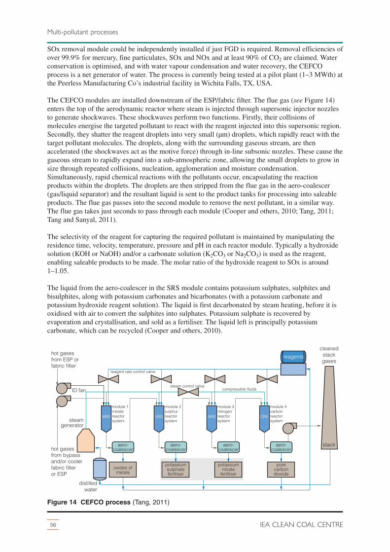
SOx removal module could be independently installed if just FGD is required. Removal efficiencies ofover 99.9% for mercury, fine particulates, SOx and NOx and at least 90% of CO2 are claimed. Waterconservation is optimised, and with water vapour condensation and water recovery, the CEFCOprocess is a net generator of water. The process is currently being tested at a pilot plant (1–3 MWth) atthe Peerless Manufacturing Co’s industrial facility in Wichita Falls, TX, USA.
The CEFCO modules are installed downstream of the ESP/fabric filter. The flue gas (see Figure 14)enters the top of the aerodynamic reactor where steam is injected through supersonic injector nozzlesto generate shockwaves. These shockwaves perform two functions. Firstly, their collisions ofmolecules energise the targeted pollutant to react with the reagent injected into this supersonic region.Secondly, they shatter the reagent droplets into very small (µm) droplets, which rapidly react with thetarget pollutant molecules. The droplets, along with the surrounding gaseous stream, are thenaccelerated (the shockwaves act as the motive force) through in-line subsonic nozzles. These cause thegaseous stream to rapidly expand into a sub-atmospheric zone, allowing the small droplets to grow insize through repeated collisions, nucleation, agglomeration and moisture condensation.Simultaneously, rapid chemical reactions with the pollutants occur, encapsulating the reactionproducts within the droplets. The droplets are then stripped from the flue gas in the aero-coalescer(gas/liquid separator) and the resultant liquid is sent to the product tanks for processing into saleableproducts. The flue gas passes into the second module to remove the next pollutant, in a similar way.The flue gas takes just seconds to pass through each module (Cooper and others, 2010; Tang, 2011;Tang and Sanyal, 2011).
The selectivity of the reagent for capturing the required pollutant is maintained by manipulating theresidence time, velocity, temperature, pressure and pH in each reactor module. Typically a hydroxidesolution (KOH or NaOH) and/or a carbonate solution (K2CO3 or Na2CO3) is used as the reagent,enabling saleable products to be made. The molar ratio of the hydroxide reagent to SOx is around1–1.05.
The liquid from the aero-coalescer in the SRS module contains potassium sulphates, sulphites andbisulphites, along with potassium carbonates and bicarbonates (with a potassium carbonate andpotassium hydroxide reagent solution). The liquid is first decarbonated by steam heating, before it isoxidised with air to convert the sulphites into sulphates. Potassium sulphate is recovered byevaporation and crystallisation, and sold as a fertiliser. The liquid left is principally potassiumcarbonate, which can be recycled (Cooper and others, 2010).
56 IEA CLEAN COAL CENTRE
Multi-pollutant processes
stack
steam control valvecompressible fluids
MRS SRS NRS CRS
hot gases from ESP or fabric filter
hot gases from bypass and/or cooler fabric filter or ESP
module 1metalsreactorsystem
module 2sulphurreactorsystem
module 3nitrogenreactorsystem
module 4carbonreactorsystem
aero-coalescer
aero-coalescer
aero-coalescer
aero-coalescer
distilledwater
potassiumsulphatefertiliser
potassiumnitrate
fertiliser
purecarbondioxide
cleanedstackgases
reagent rate control valve
oxides ofmetals
steamgenerator
reagents
ID fan
Figure 14 CEFCO process (Tang, 2011)

The process utilises a slipstream of the ‘waste steam’ leaving the last turbine that is returning via thereturn-loop to be condensed. Between 3 and 6 wt% of steam at a pressure between 0.69–2.76 MPa(100–400 psig) is required to generate the shockwaves (Tang, 2011, 2012). This steam can beconsidered as ‘borrowed water’ since the CEFCO process is a net generator of water. If steam isunavailable, then compressed air can be used to produce the shockwaves as a low cost substitute. Afurther amount of steam (heat source) is used to remove the CO2 from the aero-coalescer liquids in adecarbonation tank.
The CEFCO process can be considered a low water multi-pollutant system since it generates water,which can be recovered and recycled within the power plant. Water is produced (Tang and Sanyal,2010) through:� the reactions of the hydroxide reagent solution with CO2 resulting in bicarbonate/carbonate that
is recovered after exiting the aero-coalescer;� the water input in the chemical feed stream which is recovered through condensation from the
liberated and concentrated CO2 gas stream during the decarbonation and recovery step;� capture of the moisture condensed from the flue gas itself and the stack gas.
A material balance carried out for a 1000 MW power plant employing all four modules estimated that3886 t/MWe (4284 ton/MWe), 2941 t/MWe (3242 ton/MWe) and 2819 t/MWe (3108 ton/MWe) ofwater would be produced when burning US lignite, subbituminous and high sulphur bituminous coals,respectively. The average energy consumption of each of the four CEFCO modules would be 57 MWwhen firing lignite, 25.5 MW for the subbituminous coal, and 32.5 MW with the high sulphurbituminous coal (Tang, 2012). Thus the full four-module multi-pollutant system would have an energypenalty (parasitic load) of 22.8%, 12.4% and 13% for the lignite, subbituminous and bituminouscoals, respectively. The parasitic load could be excessive for plants firing lignite.
The reactions within the aerodynamic reactors take place within seconds and so the equipmentfootprint is small. The SRS module is smaller than a wet limestone FGD unit. The CEFCO technologycould be retrofitted or applied to new power plants. It utilises a recirculating and regenerative reagentsystem to minimise the use of reagents (such as potassium carbonate). However, this does add to thecomplexity of the process. The capital (CapEx) and operating expenditure (OpEx) costs for a1000 MW plant (with all four modules) firing lignite, subbituminous and high sulphur bituminouscoals are estimated to be US$1382 million, US$1069 million and US$1921 million, respectively. Eachmodule produces saleable products to generate revenue. The CapEx and OpEx costs for just the SRSmodule are around US$275 million and US$62 million, respectively, and the module could generate arevenue of US$208 million per year when utilising subbituminous coal. However, if the process (allfour modules) is operated in a ‘capture-only’ mode, without the production of saleable products, thenthe reagent component of the OpEx costs can be reduced by using cheaper calcium-based reagentsinstead of potassium-based ones (Tang, 2012). More information about the process can be found onCEFCO’s website (www.cefcoglobal.com).
6.4 Electron beam process
Although the electron beam process is a dry scrubbing process that simultaneously removes SO2, SO3,NOx and other acid gases, water is consumed in the conditioning of the flue gas and elsewhere. Over95% of SOx and up to 75% of NOx can be removed. The electron beam-flue gas treatment (EB-FGT)process has been demonstrated on two coal-fired plants in China, and one in Poland, and a few otherindustrial plants.
Dedusted flue gas is cooled and humidified, typically in a spray cooler. Ammonia is added as anaqueous solution to the spray cooler or separately after the spray cooler (as a gas). The lowtemperature (65–80ºC), wet (10–15% humidity) and ammonia-rich flue gas enters an irradiationreactor, where high energy electrons react with molecules in the flue gas to produce radicals that then
57Low water FDG technologies
Multi-pollutant processes

react with the SOx and NOx in the flue gas to produce sulphuric and nitric acids, respectively. Theseacids, in turn, react with the ammonia to form ammonium sulphate and ammonium nitrate. Theammonium salts (ammonium sulphates and nitrates) are collected in a downstream ESP, and sold asfertiliser. The chemical reactions are completed within seconds.
Depending on process conditions, ammonia water consumption was in the range of 150–600 kg/h atthe Polish facility in Pomorzany (Hiete and Schulte-Beerbühl, 2012). Cooling water is also needed tocool the reaction unit. A 65 MW boiler with a flue gas flow of 300,000 m3/h and removing 98% of theSO2 with electron beams consumes 108 t/d of water and 48,000 kWh/d (48 MWh/d) of electric power(PlasTEP, 2011). The process material balance carried out by PlasTEP found that the EB-FGT process(based on Polish data) consumes more water than a wet limestone FGD + SCR system, when treating1000 m3 of flue gas. Therefore this process will not be discussed any further.
6.5 EnviroScrub
EnviroScrub, developed by Enviroscrub Technologies, is a ‘closed loop’, regenerable sorbent systemcapable of removing SO2, SO3, NOx, mercury and particulates. The technology is based on thePahlman™ process, and is installed after a particulate removal device. It has only been tested atpilot-scale at a few coal-fired units when over 99% SO2, 98% NOx, and up to 99% elemental and 84%oxidised mercury were removed (Hammel, 2004).
The Pahlmanite sorbent is made up of manganese oxides and is injected, either dry or as a concentratedslurry, into a reactor, such as a spray dry absorber or fluidised bed. SOx and NOx react with manganeseoxide to form manganese sulphates and nitrates, respectively. Mercury is oxidised and absorbed on thesorbent. The spent (and unused) sorbent is then collected in the downstream fabric filter, and the cleanflue gas is emitted through the stack. The spent sorbent is regenerated using a wet chemical system. It ismixed with water and transported to the regeneration vessel where it is contacted with a hot, oxidising,aqueous solution, which dissolves the manganese sulphates and nitrates. The chemical composition andoperating conditions of the regeneration vessel are controlled so that the dissolved manganese isprecipitated to form fresh sorbent. In addition, the remaining solid sorbent is re-oxidised andre-activated. The solid manganese oxides are then separated, washed and returned to the Pahlmanitestorage tank. The solution containing the sulphate, nitrate and mercury compounds is treated to removemercury and any chlorides, and the resulting sulphate and nitrate solution (or solids if required) can besold. Some of the sulphate containing solution can be treated to produce the oxidant for use inregenerating the Pahlmanite sorbent (Hammel, 2004; Tavoulareas and Jozewicz, 2005).
Although the sorbent can be injected dry, water is consumed when regenerating the sorbent. Since theamount of water consumed in the process could not be ascertained, the technology will not bediscussed any further.
6.6 SNOX™ process
SNOX™ (previously called WSA-SNOX) is a regenerative, catalytic process, developed by HaldorTopsøe, to control SOx and NOx emissions. It consumes no water and produces a saleable sulphuricacid by-product (Lindenhoff, 2011). Large SNOX™ units are in use on a 300 MW coal-fired powerplant in Denmark (since 1991), a petcoke-fired power plant in Italy, and a heavy residual fuel oilpower plant in Austria. Over 55 small-scale units, including some that operate with just thedesulphurisation step, are operating worldwide treating a range of sulphur containing offgases.SNOX™ has also been demonstrated on a slipstream (equivalent to 35 MWe) at the Niles Station,OH, USA, burning high sulphur (2.9%) bituminous coal (NETL, 2000b). The process is designed forhigh sulphur fuels. Up to 99% of SO2 and SO3, up to 96% of NOx and essentially all the particulatesare removed (Schoubye and Jensen, 2007).
58 IEA CLEAN COAL CENTRE
Multi-pollutant processes

The SNOX™ unit is located downstream of the particulate control device. The dedusted flue gas(see Figure 15) is reheated in a heat exchanger to ~400ºC and ammonia is injected before the gasenters the NOx reduction reactor. Here NOx is catalytically reduced by ammonia to nitrogen andwater, just as in conventional SCR operation. The flue gas is then heated and SO2 is catalyticallyoxidised to SO3 in a second reactor. Later designs have integrated the two catalytic reactors into asingle vessel. The flue gas exiting the oxidation reactor passes through the hot side of the heatexchanger where it is cooled as the incoming flue gas is heated. SO3 reacts with water in the flue gasto form sulphuric acid vapour, which is then condensed into 94–95% concentrated sulphuric acid inthe WSA (Wet Sulphuric Acid) condenser.
The flue gas needs to be cleaned to below 2 mg/m3 in order to protect the SCR catalyst. This meansthat particulate emissions are very low as particulates are further removed by capture on the catalystor in condensation of the sulphuric acid. The catalyst may need to be cleaned at intervals. A catalystlifetime of up to 10 years can be expected (Halder Topsøe, 2006; Schoubye and Jensen, 2007).Surplus ammonia is used in the SCR reactor to achieve a high NOx reduction efficiency without anyproblems with ammonia slip, as all the ammonia in the gas after the SCR reactor is oxidised in theSO2 oxidation reactor to nitrogen and water vapour (NETL 2000b). The efficiency of the SO2 to SO3oxidation determines the SOx emissions since all SO3 is hydrated.
No water is consumed in the SNOX™ process and hence no waste water is produced. In addition, nowaste products are generated, only very low quantities of catalyst degradation fines (NETL, 2000b). Asaleable by-product is produced; each kg of SO2 raw gas emissions leads to 2.2 kg of saleable qualitysulphuric acid (Hiete and Schulte-Beerbühl, 2012). Furthermore, boiler thermal efficiency and grosspower production are increased since the heat produced by the exothermic reactions and by coolingthe flue gas is recovered. The cooling air discharged from the WSA condenser can be used in theboiler as combustion air. It was estimated that for a 500 MW coal-fired power plant, the heat recoveryis more than the supplemental power needed for the SNOX™ plant, and could provide a potential netgain equivalent to 8 MWe (NETL, 2000b). Even before credits for sulphuric acid sales, the operating
59Low water FDG technologies
Multi-pollutant processes
SO3 + H2O H2SO4(g) H2SO4(g) H2SO4(l)
boiler
clean flue gascooling air
blowerambient air WSA
condenser
200°C
100°C
SO2converter
400°C
SCR reactor/ denitrification
ammoniaheater
flue gasblower
sulphuricacid 95%
heat exchanger
hotcombustion
air
200°C 250°C
steam turbine /generator
coal
fluegas
ashes
ESP
air heater
stack
SO2 + 1/2O2 SO3
NOx + NH3 N2 + H2O
Figure 15 SNOX™ process (Lindenhoff, 2011)

cost of SNOX™ units decreases with increasing SOx content in the flue gas due to heat recovery(Halder Topsøe, 2006; Schoubye and Jensen, 2007). SNOX™ has lower capital requirements andlower operating and maintenance costs than a wet limestone FGD + SCR plant burning high sulphurcoals (NETL, 2000b). Treating low and medium sulphur coals, though, will cost more than a wetlimestone scrubber (Lindenhoff, 2011). Unlike wet scrubbers (see Section 3.1), SNOX™ generates noCO2. Flue gas with up to 1 vol% SO2 can be treated. Higher SO2 concentrations would requiremodifications to the plant layout (Halder Topsøe, 2006). However, SNOX™ requires more space thana typical wet FGD or SCR unit (NETL, 2000b).
6.7 SOx-NOx-Rox Box process (SNRB™)
SNRB™ is a dry process that removes SO2, NOx and particulates in a high temperature catalyticfabric filter (baghouse). The system operates at a temperature of ~425–455ºC and is located before theair heater. SO2 is removed by injecting either calcium- or sodium-based sorbents into the flue gas(DSI, see Section 5.3). NOx is removed via SCR. Ammonia is injected into the flue gas upstream ofthe fabric filter, and the SCR catalyst is incorporated in the fabric filter. The particulates, including thespent and unused sorbent, are removed by the fabric filter bags.
In 1992-93, the SNRB™ system was demonstrated on a 5 MW slipstream (1000 m3/h flue gas) at theRE Burger power plant, OH, USA, burning bituminous coal (3.5% S). SO2 removal efficiencies of80–90% were achieved at a Ca/S molar ratio of ~1.8–2, whilst SO2 removal was >90% with sodiumbicarbonate injection. NOx removal was >90% with an ammonia slip of less than 5 ppm. Over 99.9%of particulates were captured (US DOE, 1999; NETL, 2000c; Tavoulareas and Jozewicz , 2005).
SNRB™ has a small footprint, and is simple to operate. No water is consumed in the process. SinceSO2 and particulates are removed before the air heater, fouling and corrosion potential aresubstantially reduced, allowing the air heater to operate at a lower flue gas outlet temperature. Afurther advantage is the potential for enhanced energy recovery and improved boiler efficiency. Thecapital and operating costs of a SNRB™ system are expected to be lower than a system incorporatingseparate wet FGD, SCR and particulate removal components. However, it may not be an economicchoice for applications requiring SO2 removal over ~85% (US DOE, 1999). Since the small-scaleRE Burger demonstration in the mid-1990s, the technology does not appear to have been developedany further or tested at a larger scale.
60 IEA CLEAN COAL CENTRE
Multi-pollutant processes

7 Conclusions
61Low water FGD technologies
A wide variety of FGD technologies are available for controlling SOx emissions that vary in theamount of water they consume. Technologies with a low water usage are important because of thelarge number of FGD systems being installed in response to tightening emission regulations.Reducing water usage is particularly important in arid regions of the world and in areas subject todrought. There is therefore a need for FGD systems that meet the following criteria:� low water consumption;� high SO2 and SO3 removal efficiency;� high reliability;� low capital, operating and maintenance costs;� low auxiliary power consumption;� saleable or usable by-product.
Limestone wet scrubbers, the most common FGD system for controlling SO2 emissions, can removeover 98% of SO2, have a high reliability and produce saleable gypsum. Auxiliary power consumptionis around 1.2–2%, depending on the coal sulphur content. However, they increase a plant’s CO2emissions (CO2 is a by-product of the desulphurisation process) and require large supplies of water.Wet scrubbers are responsible for around 10–15% of the evaporative water losses in coal-fired powerplants equipped with water cooling systems. The figure is considerably higher in plants employingdry/air cooling systems where wet scrubbers account for 40–70% of total site water usage.Technologies to reduce the water losses could therefore save significant amounts of water.
Evaporative water losses can be reduced by some 40–50% when the flue gas is cooled from around140ºC to 90–100ºC before it enters the wet scrubber. This is commonly carried out in Japan and Europeusing regenerative heat exchangers, but is less common in countries such as the USA. Additionalbenefits from cooling the flue gas include smaller flue gas volumes to be treated, and hence smaller FGDsystems and stack requirements for new plants, and improved performance of existing ESPs and fabricfilters. Moreover, mercury capture increases, and installing the heat exchangers upstream of theparticulate control device can reduce SO3 emissions to below 0.1 ppm through condensation on the flyash. But regenerative heat exchangers are expensive, and can have high operating and maintenance costs.Power consumption increases, and leakage of the unscrubbed gas into the scrubbed gas decreases SO2removal efficiency. Non-leakage heat exchangers are commercially available.
Recovering 20% of the water in the flue gas would enable a power plant to become self-sufficient, butif over 20% is captured, then the plant would become a water supplier instead of a consumer. Inaddition, producing a low temperature flue gas with reduced acid and water vapour contents wouldlower the cost of capturing CO2 in amine and ammonia scrubbers. Installing condensing heatexchangers can recover both heat and water from the flue gas. The recovered heat could be used in theboiler or turbine cycle to improve boiler efficiency. Water capture efficiency is limited to around 20%when cold boiler feedwater is the cooling fluid, but reaches some 70% with an inlet cooling watertemperature of 24ºC. It can be further enhanced through a combination of water- and air-cooled heatexchangers. Condensing the flue gas to recover the water requires a large cooling capacity, can lead tocorrosion and fouling of the heat exchanger, and increases auxiliary power consumption. Therecovered water has to be treated before it can be recycled, and this can be costly. Water condensationis more efficient with high moisture coals and at lower flue gas temperatures, and therefore may notbe a practical option for low moisture coals.
Membranes that are highly selective for water vapour can recover at least 40%, and up to 90%, of thewater vapour in the flue gas exiting the wet scrubber. A membrane condenser system also recovers thelatent heat in the flue gas. The recovered water is mineral-free and can be utilised directly within thepower plant, by industry or for public consumption purposes. No wastewater is produced. Parasitic

power consumption is around 0.1–1.1%. An economic analysis has shown that membrane systemsproduce demineralised water at a lower cost than a conventional demineralisation plant sited in theNetherlands. Combining the water capture membranes with CO2-selective membranes could lowerCO2 emissions at the same time.
Pilot-scale tests have shown that a liquid desiccant-based dehydration system can recover 50–70% ofthe water vapour in the flue gas exiting the wet scrubber. Low grade heating and cooling sourceswithin the power plant could be utilised to minimise the power needs of the process. The recoveredwater can be employed for direct cycle make-up after minimal treatment or used directly for otherpower plant applications. The economic viability of the process strongly depends on the location ofthe plant. Corrosion could be an issue with salt-based desiccants, and questions remain as to thelong-term interaction of the desiccant with the flue gas, contamination of the desiccant solution byflue gas constituents, and precipitates that may form and how to handle them.
The semi-dry scrubbing systems, namely spray dry scrubbers (SDSs) and circulating dry scrubbers(CDSs), consume about 60% less water than wet scrubbers. Furthermore, they have the advantages oflower investment costs (than a similar sized wet scrubber), no production of wastewater, dryby-products, lower parasitic power consumption, a smaller footprint (which may be easier for retrofitapplications), and additionally capture over 95% of the SO3, HCl, HF and oxidised mercury. The maindrawback of SDSs compared to wet scrubbers is their lower SO2 removal efficiency (90–97%).State-of-the-art CDSs can remove over 98%, approaching the efficiency of wet scrubbers. Operatingcosts are generally higher than those for wet scrubbers mainly due to the higher sorbent costs, andmaintenance costs of fabric filters in CDS systems can be higher due to their greater wear from therecycling of by-products. Multiple absorber vessels are required for units with a capacity higher thanabout 400 MW.
SDSs are typically used at power plants burning low to medium sulphur coals, whilst CDSs can beapplied to units burning low to high sulphur coals. Both systems have a good turndown capability, andsimilar water usage, power consumption and capital costs. CDS systems consume some 20% morereagents than SDSs. Although CO2 is not generated in the desulphurisation process, it is emitted fromthe on-site lime kilns (if present).
Sorbent injection processes have the lowest water consumption of the various FGD systems,consuming no water, or a minimal amount if the sorbent needs hydrating or the flue gas is humidifiedto improve performance. They are simple to install and operate, easy to retrofit with their small spacerequirements, and produce no wastewater. A co-benefit is the capture of some of the HCl, HF andmercury in the flue gas. The by-products are dry and so are easier to handle and manage than the wetby-products from wet scrubbers. As a consequence, the capital cost and energy consumption of thesorbent injection systems are considerably lower than the semi-dry and wet FGD processes. Parasiticpower consumption is around 0.2% of electric capacity. Nevertheless, operating costs are generallyhigher mainly due to the high consumption of the sorbent. The bulk of the operating cost is the priceof the sorbent. In general, calcium-based sorbents are cheaper than the sodium-based ones. Thesorbent injection systems are best suited for use in small (<300 MWe) power plants that utilise low tomedium sulphur coals, and where only a moderate SO2 removal efficiency is required.
The main drawback of injection systems is the poor utilisation and SO2 removal efficiency of thesorbents. The SO2 (and SO3) removal rate is dependent on a number of factors, including the injectionlocation, flue gas temperature, sorbent particle size and reactivity, residence time, and the type ofparticulate control device. A power plant with fabric filters installed downstream of the injection pointgenerally achieves a higher (~5–10%) SOx removal efficiency than one with ESPs, as the filter cakeon the fabric filter provides additional time and contact for the SO2/SO3 to react with the sorbent.Injecting calcium-based sorbents either into the furnace or duct removes up to 60% of the SO2. Theefficiency can be increased by around 10% with flue gas humidification. Injecting the sorbent as aslurry, with additives or recycling the sorbent after reactivation can also improve the utilisation and
62 IEA CLEAN COAL CENTRE
Conclusions

SO2 removal efficiency. Sodium-based sorbents have a higher efficiency, capturing up to 90% of theSO2 when injected into the duct, without the need for flue gas humidification. Sodium-based sorbents,though, cannot be used to capture SO2 within the furnace. Injecting calcium-based sorbents decreasesthe efficiency of ESPs due to the increase in ash resistivity, requiring additional measures to mitigatethis effect. On the other hand, sodium compounds may improve ESP performance due to the increasein ash resistivity. A disadvantage with the injection of carbonate-based sorbents (such as limestone,sodium carbonate and trona) is the formation of CO2, thus adding to the plant’s CO2 emissions. Theby-products from the sorbent injection have little economic value.
When present in sufficient quantity, SO3 (via the formation of H2SO4) can lead to stack opacityproblems, increase corrosion and fouling of ductwork and equipment downstream of the furnace,decreasing their efficiency and penalising overall plant heat rate. SO3 formation increases when anSCR is installed to control NOx emissions. Injecting calcium hydroxide and sodium-based sorbentsinto the ductwork downstream of the SCR can reduce SO3 emissions more efficiently than wetscrubbers. A higher SO3 removal efficiency is achieved with sodium-based sorbents, up to 98% insome cases. Trona, though, is more difficult to handle than hydrated lime due to its small particle size(~28 µm), its cohesiveness, and affinity for moisture. In addition, care must be taken to avoid theformation of liquid sodium bisulphate which can foul the downstream equipment and ductwork.
A concern with sorbent injection and semi-dry scrubbing processes is the effect of the collected spentsorbent on the saleability of the fly ash. A particulate collection device prior to the FGD unit mayenable the fly ash to be sold, as well as the desulphurisation products. Calcium sulphate, for instance,could be sold as a fertiliser. Pre-collection of fly ash is widely practised in Europe but is not ascommon in the USA. The spent sorbent/fly ash mixtures from the processes have little marketablevalue, unlike the gypsum by-product from limestone wet scrubbers. More research on ways to utilisethe by-products is required. Moreover, there is a need to develop effective reagents that can removeSOx at a lower sorbent:sulphur molar ratio, and hence generate less by-products. The development ofsorbents with a higher reactivity for sulphur that could be used dry, and without the need for flue gashumidification, could lower water usage.
Multi-pollutant processes that remove several regulated pollutants in one system may be more cost-effective than separate components. The commercial ReACT™ process is a regenerable system thatuses only 1% of the water required by conventional wet scrubbers. Over 99% of SO2 and SO3,20–80% NOx, >90% of mercury (both elemental and oxidised) and around 50% of the particulates areremoved in the process when burning low to medium sulphur coals. Parasitic power consumption isabout 0.7%. Saleable by-products are produced (the fly ash is pre-collected), and the mercury can berecovered from the spent activated coke off-site. Operating costs could be reduced if cheaper andmore efficient activated carbon sorbents were developed.
The commercial SNOX™ is a regenerable catalytic process that consumes no water and removes upto 99% of SO2 and SO3, up to 96% of NOx and essentially all of the particulates. It produces saleablesulphuric acid and fly ash (since the ash is pre-collected), and no waste products, except for very lowquantities of catalyst degradation fines. There is no parasitic power consumption because of the heatrecovery features and, on a 500 MW power plant, a potential net power gain. SNOX™ has lowercapital, operating, and maintenance costs than a wet limestone FGD + SCR plant burning high sulphurcoals, but will cost more than a wet scrubber when combusting low and medium sulphur coals. Theprocess was designed for high sulphur fuels.
The desulphurisation component of the two newer technologies, Cansolv® and CEFCO, can beinstalled separately if just FGD is required. The Cansolv® SO2 system can be integrated with a CO2capture module to remove about 90% of the CO2, whilst the CEFCO sulphur reactor system can becombined with modules removing over 99.9% of the trace metals (including mercury), fineparticulates and NOx, and around 90% of CO2. The sulphur modules are among the most efficientSO2 removal processes available with both technologies removing over 99.9% of SO2.
63Low water FDG technologies
Conclusions

A separate SO3 removal system may be required with the Cansolv® SO2 scrubbing system in order tomeet strict SO3 emission regulations since only some 50% of SO3 is captured by the proprietary aminesolvent. Water consumption is relatively low, primarily because of the regeneration of the amine/watersolvent and the recovery of water from the SO2-rich gas. Furthermore, heat recovery reduces both theamount of steam necessary to regenerate the solvent and the amount of cooling water needed to coolthe solvent. Energy consumption is relatively low, the footprint is smaller than a wet FGD system, anda saleable by-product can be produced from the recovered SO2. The pre-collected fly ash can be sold.
The CEFCO process, currently at the pilot stage, captures over 99.9% of both SO2 and SO3. It is a netgenerator of water, saleable fertilisers can be produced and the fly ash sold (since it is pre-collected).Parasitic power consumption for the sulphur reactor module is around 3% when firing subbituminousand bituminous coals, and nearly 6% with lignite. The energy penalty (~23%) could be excessive inlignite power plants for the full four module multi-pollutant system.
To conclude, there are a number of commercial low water FGD processes available that are suitablefor coal-fired power plants in areas where water is scarce. These technologies are either completelydry or have a relatively low water usage. Moreover, recovery of the water vapour in the flue gasexiting conventional wet scrubbers could enable a power plant to become a net supplier of water.Furthermore, technologies that produce a low temperature flue gas with low SOx and water vapourcontents could lower CO2 scrubbing costs, if future regulations require the installation of CO2 controlsystems.
64 IEA CLEAN COAL CENTRE
Conclusions

8 References
65Low water FGD technologies
Adams D (2010) Flue gas treatment for CO2 capture. CCC/169, London, UK, IEA Clean CoalCentre, 61 pp (Jun 2010)Adamson V (2008)Wet scrubber system fundamentals. Presentation at: Worldwide Pollution ControlAssociation Duke energy seminar, Concord, NC, USA, 3-5 Sep 2008. Available from:www.wpca.info Livonia, MI, USA, Worldwide Pollution Control Association, 49 pp (2008)Ahman S, Barranger C B, Maurin P G (2002) Alstom Power’s Flash Dryer Absorber for flue gasdesulfurization. Paper presented at: International joint power generation conference, Phoenix, AZ,USA, 24-26 Jun 2002. 7 pp (2002)AirPol Inc (1999) 10-MWe demonstration of gas suspension absorption. Project performancesummary. Clean Coal Technology Demonstration Program. DOE/FE-0389, Washington, DC, USA,US Department of Energy, 12 pp (Jun 1999)Ake T, Licata A (2011) Circulating dry scrubbers comply with the EPA Maximum AchievableControl Technology limits. Paper presented at: Power-Gen international conference, Las Vegas, NV,USA, 13-15 Dec 2011. 15 pp (2011) Alstom (2008) NID™ flue gas desulphurization system for the power industry. Available from:www.alstom.com/power/fossil/coal-oil/air-quality-control-systems/flue-gas-desulphurisationLevallois-Perret, France, Alstom, 4 pp (2008)Alstom (2012) NID™ flue gas desulphurisation. Baden, Switzerland, Alstom (Switzerland) Ltd, 2 pp(2012)Babcock & Wilcox (2009) Spray dry flue gas desulfurization systems. Barberton, OH, USA,Babcock & Wilcox Power Generation Group, 12 pp (2009)Benson L B (2006) Use of magnesium hydroxide for reduction of plume visibility in coal-firedpower plants. In: Combined power plant air pollutant control ‘Mega’ symposium, Baltimore, MD,USA, 28-31 Aug 2006. Pittsburgh, PA, USA, Air and Waste Management Association, vol 2, pp1002-1020 (2006)Benson L B, Smith K J, Roden R A, Loch E, Potts J (2003) Control of sulfur dioxide and sulfurtrioxide using by-product of a magnesium-enhanced lime FGD system. Paper presented at: Combinedpower plant air pollutant control ‘Mega’ symposium, Washington, DC, USA, 19-22 May 2003. 15 pp(2003)Biehn C (2011a) Using dry sorbent injection to meet the utility MACT. Presentation at: WorldwidePollution Control Association Illinois regional technical seminar, Normal, IL, USA, 13-15 Sep 2011.Available from: www.wpca.info Livonia, MI, USA, Worldwide Pollution Control Association, 34 pp(2011)Biehn C (2011b) Using dry sorbent injection to control SO3 and HCl. Presentation at: WorldwidePollution Control Association Duke Energy FF/HAPS seminar, Plainfield, IN, USA, 12-13 Oct 2011.Available from: www.wpca.info Livonia, MI, USA, Worldwide Pollution Control Association, 35 pp(2011)Blythe G M (2004) Furnace injection of alkaline sorbents for sulfuric acid removal. Final report.Available at:www.netl.doe.gov/technologies/coalpower/ewr/pm_emissions_control/pubs/40718final.PDFPittsburgh, PA, USA, National Energy Technology Laboratory, 91 pp (Jan 2004)Bostick G L, Moss S L (2011) Installation of CFB scrubber at Basin Electric Power Cooperative’sDry Fork Station - Unit #1. In: International conference on air quality VIII, proceedings, Arlington,VA, USA, 24-27 Oct 2011. Grand Forks, ND, USA, University of North Dakota, Energy andEnvironment Research Center, 6 pp (2011)Bowes E, Rhodes R B, Hamel B T, Benson S A, McCollor D P, Laudal D L (2007) SO3 control:Dominion demonstrates CleanStack technology. Available at: www.coalpowermag.com/issues/2007-03-01/ Coal Power; 1-6 (1 Mar 2007)Buecker B, Hovey L (2011) Circulating dry scrubbers: a new wave in FGD? Power Engineering;115(11); 176,178,180,182 (Nov 2011)

Buschmann J (2008) DFGD process equipment. Presentation at: WPCA scrubber training,Savannah, GA, USA, 13 Jul 2008. Available from: www.wpca.info Livonia, MI, USA, WorldwidePollution Control Association, 56 pp (Jul 2008)Bustard J, Martin C, Sjostrom S, Filippelli G, Wewer R, Miller R (2011) Activated carbon anddry sorbent injection systems: preparing for mercury and air toxics and cross state air pollutioncontrol rules. International conference on air quality VIII, proceedings, Arlington, VA, USA, 24-27Oct 2011. Grand Forks, ND, USA, University of North Dakota, Energy and Environment ResearchCenter, 12 pp (2011)Campobenedetto E J, Silva A A (2011) Low cost multi-pollutant control solution demonstrations.Paper presented at: Air & Waste Management Association annual conference, Orlando, FL, USA, 21-24 Jun 2011. 5 pp (2011)Cansolv Technologies (nd) Cansolv. State of the art gas absorption solutions. Available at:www.cansolv.com/rtecontent/document/Cansolv_Technologies1.pdf Montreal, PQ, Canada, CansolvTechnologies, 20 pp (nd)Cansolv Technologies (2011) Cansolv technology to remove SO2 from major Chinese coal-firedpower plant. Available from: www.cansolv.com Montreal, PQ, Canada, Cansolv Technologies, 2 pp(11 Jul 2011)Carney B, Feeley T J, McNemar A (2008) NETL power plant water research program. Presentationat: EPRI advanced cooling technology workshop, Charlotte, NC, USA, 8-9 Jul 2008. 39 pp (2008)Chen Y, Liu M (2011) Opportunity for the new emission standard of air pollutants for thermal powerplants in China. Presentation at: IEA Clean Coal Centre Executive Committee meeting, London, UK,19-20 Oct 2011. 20 pp (2011)Chenevey J P, Smith J M (2011) Circulating dry scrubber applicability for industrial and smallutility boilers. Presentation at: ICAC/MARAMA advances in air pollution control workshop,Baltimore, MD, USA, 18-19 May 2011. Available from:www.icac.com/files/public/Chenevey_MARAMA_051811.pdf Washington, DC, USA, Institute ofClean Air Companies, 21 pp (2011)Cheng J, Zhou J, Liu J, Zhou Z, Huang Z, Cao X, Zhao X, Cen K (2003) Sulfur removal at hightemperature during coal combustion in furnaces: a review. Progress in Energy and CombustionScience; 29(5); 381-405 (2003)Cho K J (2007) A modeling and experimental study of the conversion of trona to increase itsreactivity with SO2 in dry injection system. PhD thesis, Cincinnati, OH, USA, University ofCincinnati, Department of Civil and Environmental Engineering of the College of Engineering, 211pp (2007)Chu Y H, Guo J X, Liang J, Zhang Q B, Yin H Q (2010) Ni supported on activated carbon ascatalyst for flue gas desulfurization. Science China Chemistry; 53(4); 846-850 (Apr 2010)Clyde Bergemann (2010) Environmental retrofit project for NRG Energy completed. ClydeBergemann News; (2); 5 (2010)Cooper H B H, Tang R E, Degling D E, Ewan T K, Ewan S M (2010) Process and apparatus forcarbon capture and elimination of multi-pollutants in flue gas from hydrocarbon fuel sources andrecovery of multiple by-products. US Patent 7,842,264 B2, Alexandria, VA, USA, US Patent andTrademark Office, 41 pp (30 Nov 2010)Copen J H, Sullivan T B, Folkedahl B C (2005) Principles of flue gas water recovery system. Paperpresented at: Power-Gen international, Las Vegas, NV, USA, 6-8 Dec 2005. 12 pp (2005)Couch G (2005) Use of coal in areas of water shortage. CCC/103, London, UK, IEA Clean CoalCentre, 88 pp (Nov 2005)Cremer M A, Wang D H, Senior C L (2008) Testing and model based optimization of SO2 removalwith trona in coal fired utility boilers. In: Power plant air pollutant control ‘Mega’ symposium,Baltimore, MD, USA, 25-28 Aug 2008. Pittsburgh, PA, USA, Air and Waste ManagementAssociation, CD-ROM, Paper 137, 14 pp (2008)Daal L (2011) How the power industry can contribute to reducing the global water shortage. PowerEngineering International; 19(5); 62,64,66,68-69 (May 2011)Daal L, Kamphuis H, Stam A, Konings T, Huibers M, van Rijen S, de Ruijter J (2012)Evaluation of different water vapor capture technologies and energy modeling results for membrane
66 IEA CLEAN COAL CENTRE
References
technology. Paper presented at: Power-Gen Europe conference, Cologne, Germany, 12-14 Jun 2012. Available at: www.watercapture.eu/downloads/paper-powergen-europe.pdf 21 pp (2012)Davis M B, Toombs W R, Boyle J, Hermanas G, Benisvy H, Schulz K W (2008) Controlling SO3,slag and fouling resulting in improved heat rates, better efficiency and allowing for fuel flexibility -Santee Cooper, Cross station case study. Paper presented at: EUEC conference, Tucson, AZ, USA,Jan 2008. 24 pp (2008)Day K (2010) How particle size affects SO2 and SO3 removal performance for a dry sorbentinjection system. Presentation at: Power-Gen international conference, Orlando, FL, USA, 14-16 Dec2010. 16 pp (2010) de Vos F G, Heijboer R, van Deelen-Bremer H M (2008) Power plant: from water guzzler to waterproducer. Power Engineering International; 16(10); 26-28 (Dec 2008)Dene C, Baker L A, Keeth R J (2008a) FGD performance capability. In: Power plant air pollutantcontrol ‘Mega’ symposium, Baltimore, MD, USA, 25-28 Aug 2008. Pittsburgh, PA, USA, Air andWaste Management Association, CD-ROM, Paper 62, 22 pp (2008)Dene C, Gilbert J, Jackson K, Miyagawa S (2008b) ReACT process demonstration at ValmyGenerating Station. In: Power plant air pollutant control ‘Mega’ symposium, Baltimore, MD, USA,25-28 Aug 2008. Pittsburgh, PA, USA, Air and Waste Management Association, CD-ROM, Paper123, 13 pp (2008)DTI (2000) Flue gas desulphurisation (FGD) technologies. Technology Status Report 012, London,UK, Department of Trade and Industry, 12 pp (Mar 2000)EPRI (2007) CoalFleet guideline for advanced pulverized coal power plants. Version 1. EPRI report1012237, Palo Alto, CA, USA, Electric Power Research Institute, 206 pp (2007)European Commission (2006) Integrated pollution prevention and control reference document onbest available techniques for large combustion plants. Available from:http://eippcb.jrc.es/reference/lcp.html Seville, Spain, European Commission, Joint Research Centre,Institute for Prospective Technological Studies, European IPPC Bureau, 618 pp (Jul 2006)Evans A P, Gresh J A, Birmingham W, Benson S A, McCollor D P (2007) Benchmarking SO3removal - the CleanStack® process. In: International conference on air quality VI, proceedings,Arlington, VA, USA, 24-27 Sep 2007. Grand Forks, ND, USA, University of North Dakota, Energyand Environment Research Center, 10 pp (2007)Fan L S, Thomas T, Butalia T, Walker H, Weavers L, Gupta H (2005) Demonstration of OhioState Carbonation and Ash Reactivation (OSCAR) process and by-product characterization. Finalreport. Columbus, OH, USA, Ohio Coal Development Office, 223 pp (2005)Feeley T, Pletcher S, Carney B, McNemar A T (2006) Department of Energy/National EnergyTechnology Laboratory’s power plant-water R&D program. Paper presented at: Power-geninternational conference 2006, Orlando, FL, USA, 28-30 Nov 2006. 20 pp (2006)Fernando R (2003) SO3 issues for coal-fired plant. CCC/72, London, UK, IEA Clean Coal Centre,54 pp (Sep 2003)FGD & DeNOx Newsletter (2012) NID system for 630 MW Brayton Point 3. FGD & DeNOxNewsletter; (405); 7 (Jan 2012)FLSmidth (2010) Gas suspension absorber. Available from: www.flsmidth.com Valby, Denmark,FLSmidth, 9 pp (2010)Folkedahl B C, Weber G F, Collings M E, Copen J, Sullivan T, Deen P (2006) Water extractionfrom coal-fired power plant flue gas. Final report. Available from:www.netl.doe.gov/technologies/coalpower/ewr/water/pp-mgmt/eerc.html Morgantown, WV, USA,National Energy Technology Laboratory, 157 pp (Dec 2006)Gao X, Zhong Y, Wu Z, Zhang G, Evans A, Jiang M, Luo Z, Ni M, Cen K (2010) Operatingexperience of CFB semi-dry FGD with novel humidification technology in China. Paper presented at:Coal-Gen 2010 conference, Pittsburgh, PA, USA, 10-12 Aug 2010. 19 pp (2010)Głomba M, Mazurek J (2008) Desulphurization of boiler flue gas in circulation fluidized bed -foreign and domestic experience. Environment Protection Engineering; 34(4); 165-175 (2008)Graf-Wulff (2011) Basin Electric Power Cooperative Dry Fork Station, Gillette/Wyoming/USA.Friedrichsdorf, Germany, Graf-Wulff GmbH, 4 pp (2011)Gray S, Miller S, Meserole F, Harpenau M (2005) “In-situ” SBS Injection™ technology for SO3
67Low water FDG technologies
References

control: summary of operating performance and economics. In: International conference on airquality V, proceedings, Arlington, VA, USA, 19-21 Sep 2005. Grand Forks, ND, USA, University ofNorth Dakota, Energy and Environment Research Center, 15 pp (2005)Gray S, Harpenau M, Copsey P (2008) Ultra-high SO3 removal: SBS Injection™ as an alternativeto W-ESP. In: Power plant air pollutant control ‘Mega’ symposium, Baltimore, MD, USA, 25-28 Aug2008. Pittsburgh, PA, USA, Air and Waste Management Association, CD-ROM, Paper 132, 14 pp(2008)Green M E (2007) Gas to gas heat exchanger design for FGD gas reheating. Available from:webapp.psc.state.md.us Baltimore, MD, USA, Public Service Commission, 6 pp (2007)Hakka L (2007) Integrated regenerable SO2 and CO2 capture. In: International Test Network for CO2capture: report on 10th workshop, Lyon, France, 24-25 May 2007. Report 2007/08, Cheltenham,UK, IEA Greenhouse Gas R&D Programme, pp 156-173 (Jul 2007)Halder Topsøe (2006) The Topsøe SNOX™ technology for cleaning of flue gas from combustion ofpetroleum coke and high sulphur petroleum residues. Available from: www.topsoe.com Lyngby,Denmark, Halder Topsøe, 11 pp (2006)Hammel C (2004) Pahlman process shows promise. Power (NY); 148(8); 60,62-63 (Oct 2004)Harris M (2006) Ohio University case study - MACT compliance “Fluesorbent injection”. Paperpresented at: CIBO industrial emissions control technology IV conference, Toledo, OH, USA, 31 Jul-3 Aug 2006. vp (2006)Heebink L V, Buckley T D, Hassett D J, Zacher E J, Pflughoeft-Hassett D F, Dockter B A(2007) Current status of spray dryer absorber material characterization and utilization. In:Proceedings, world of coal ash (WOCA) conference, Covington, KY, USA, 7-10 May 2007.Lexington, KY, USA, University of Kentucky, Center for Applied Energy Research, CD-ROM, 13 pp(2007)Heldebrant D J, Yonker C R, Jessop P G, Phan L (2009) Reversible uptake of COS, CS2, andSO2: ionic liquids with o-alkylxanthate, o-alkylthiocarbonyl, and o-alkylsulfite anions. Chemistry - AEuropean Journal; 15(31); 7619-7627 (2009)Hiete M, Schulte-Beerbühl S (2012) Emerging techniques and technologies for large combustionplants up to 500 MWth capacity. EmTech50-500 subgroup final report. Available at:www.unece.org/fileadmin/DAM/env/documents/2012/air/WGSR_50th/EGTEI_10-04.pdf Angers,France, Agence de l’Environment et de la Maîtrise de l’Energy (ADEME), 80 pp (Mar 2012)Hitchin P (2011) Is Europe ready for the IED and willing? Power Engineering International; 19(10);40,42-45 (Nov 2011)Hopkins M W, Muoh O F (2010) Predicting PAC, hydrated lime, and trona injection effectivenessin flue gas systems using CFD and physical flow analyses for optimized nozzle design. Paperpresented at: 35th international technical conference on coal utilization & fuel systems, Clearwater,FL, USA, 6-10 Jun 2010. 6 pp (2010)IEA (2011) World energy outlook 2011. Paris, France, International Energy Agency, 659 pp (2011)Jiang Y, Wu M-C M, Su Q, Lu M, Lin C (2011) Dry CFB-FGD by-product utilization -international prospectives. In: Proceedings, world of coal ash (WOCA) conference, Denver, CO,USA, 9-12 May 2011. Lexington, KY, USA, University of Kentucky, Center for Applied EnergyResearch, CD-ROM, 7 pp (2011)Jones J K, Weilert C V (2011) Comparison of two semi-dry FGD technologies: spray dryerabsorber (SDA) vs. circulating dry scrubber (CDS). Paper presented at: Power-Gen internationalconference, Las Vegas, NV, USA, 13-15 Dec 2011. 9 pp (2011)Just P-E, Shaw D (2008) Cansolv SO2 control and CO2 capture in a coal fired power plant. In:Power plant air pollutant control ‘Mega’ symposium, Baltimore, MD, USA, 25-28 Aug 2008.Pittsburgh, PA, USA, Air and Waste Management Association, CD-ROM, Paper 53, 15 pp (2008)Klett M G, Kuehn N J, Schoff R L, Vaysman V, White J S (2005) Power plant water usage andloss study. Available at:www.netl.doe.gov/technologies/coalpower/gasification/pubs/pdf/WaterReport_IGCC_Final_August2005.pdf Morgantown, WV, USA, National Energy Technology Laboratory, 107 pp (Aug 2005)Klett M G, Kuehn N J, Schoff R L, Vaysman V, White J S (2007) Power plant water usage andloss study. Available at:
68 IEA CLEAN COAL CENTRE
References

www.netl.doe.gov/technologies/coalpower/gasification/pubs/pdf/WaterReport_Revised%20May2007.pdf Morgantown, WV, USA, National Energy Technology Laboratory, 104 pp (May 2007)Kohan S M, Rettig T W, Torbov T S, Gale T K (2008) Bringing down the cost of SO2 and NOxremoval. Power (NY); 152(10); 87-88,90,92-93 (Oct 2008)Kong Y, Wood M D (2010) Dry injection of trona for SO3 control. Power (NY); 154(5); 114-119(May 2010)Levy E, Bilirgen H, Jeong K, Kessen M, Samuelson C, Whitcombe C (2008) Recovery of waterfrom boiler flue gas. Final technical report. Available from:www.netl.doe.gov/technologies/coalpower/ewr/water/pp-mgmt/lehigh2.html Morgantown, WV, USA,National Energy Technology Laboratory, 97 pp (Dec 2008)Levy E, Bilirgen H, DuPont J (2011) Recovery of water from boiler flue gas using condensing heatexchangers. Final technical report. Available from:www.netl.doe.gov/technologies/coalpower/ewr/water/pp-mgmt/heat-exchanger.html Morgantown,WV, USA, National Energy Technology Laboratory, 155 pp (2011)Li Y, Nishioka M, Sadakata M (1999) High calcium utilization and gypsum formation for drydesulfurization process. Energy & Fuels; 13(5); 1015-1020 (Sep-Oct 1999)Li J, Kobayashi N, Hu Y (2007) A new flue gas activation process for SO2 removal with activatedcoke in coal power plant. Journal of Environment and Engineering; 2(4); 740-751 (2007)Li J, Kobayashi N, Hu Y (2008) Effect of additive on the SO2 removal from flue gas by activatedcoke. Journal of Environment and Engineering; 3(1); 92-99 (Apr 2008)Li J, Kobayashi N, Hu Y (2009) Performance of V2O5/AC activated with the flue gas on SO2removal. Journal of Environment and Engineering; 4(1); 176-187 (Apr 2009)Li Y, Song C, You C (2010a) Experimental study on abrasion characteristics of rapidly hydratedsorbent for moderate temperature dry flue gas desulfurization. Energy & Fuels; 24(3); 1682-1686(Mar 2010)Li Y, You C, Song C (2010b) Adhesive carrier particles for rapidly hydrated sorbent for moderate-temperature dry flue gas desulfurization. Environmental Science and Technology; 44(12); 4692-4696(Jun 2010)Li Y, Zheng K, You C (2011) Experimental study on the reuse of spent rapidly hydrated sorbent forcirculating fluidized bed flue gas desulfurization. Environmental Science and Technology; 45;9421-9426 (2011)Licata A, Brunner C, Gasiorowski P, Baernthaler K (2004) First 8000 hours of successfuloperation of a fluid bed-FGD system at Unit #2 Siekierki heating plant. Paper presented at: Power-Gen international conference, Orlando, FL, USA, 30 Nov-2 Dec 2004. Available at:www.babcockpower.com/pdf/bpe-05.pdf 18 pp (2004)Lindenhoff P (2011) Efficient and reliable solutions for flue gas cleaning. Presentation at:EXPPERTS 2011 conference, London, UK, 27-28 Sep 2011. 36 pp (2011)Liu Y, Bisson T M, Yang H, Xu Z (2010) Recent developments in novel sorbents for flue gas cleanup. Fuel Processing Technology; 91(10); 1175-1197 (Oct 2010)Ma J, Liu Z, Liu Q, Guo S, Huang Z, Xiao Y (2008) SO2 and NO removal from flue gas overV2O5/AC at lower temperatures - role of V2O5 on SO2 removal. Fuel Processing Technology; 89(3);242-248 (Mar 2008)Maina P, Mbarawa M (2011) Investigating effects of zeolites as an agent to improve limestonereactivity toward flue gas desulfurization. Energy & Fuels; 25(5); 2028-2038 (May 2011)Matsushima N, Li Y, Nishioka M, Sadakata M, Qi H, Xu X (2004) Novel dry-desulfurizationprocess using Ca(OH)2/fly ash sorbent in a circulating fluidized bed. Environmental Science andTechnology; 38(24); 6867-6874 (Dec 2004)Maziuk J (2007) Dry injection of trona sorbent to mitigate SOx, NOx and Hg emissions. In:International conference on air quality VI, proceedings, Arlington, VA, USA, 24-27 Sep 2007. GrandForks, ND, USA, University of North Dakota, Energy and Environment Research Center, 9 pp (2007)Minchener A (2012) Non-greenhouse gas emissions from coal-fired power plants in China.CCC/196, London, UK, IEA Clean Coal Centre, 53 pp (Apr 2012)Miyagawa S, Miya M (2008) Regenerative activated coke technology (ReACT) - a commercialmulti-pollutant control technology. In: Proceedings, 7th international symposium on gas cleaning at
69Low water FDG technologies
References
high temperatures, Newcastle, NSW, Australia, 23-25 Jun 2008. Newcastle, NSW, Australia,University of Newcastle, Chemical Engineering, CD-ROM, 11 pp (2008)Morris L (2010) Acid gas emission control measures. Power Engineering; 114(10); 54,56,58(Oct 2010)Morris L (2012) The ins and outs of SO2 control. Power Engineering; 116(6); 44,46-48,50,52(Jun 2012)Moser R E (2006) Benefits of effective SO3 removal in coal-fired power plants: beyond opacitycontrol. In: Power plant air pollutant control ‘Mega’ symposium, Baltimore, MD, USA, 28-31 Aug2006. Pittsburgh, PA, USA, Air and Waste Management Association, vol 2, pp 1037-1051 (2006)Moser R E (2007) SO3’s impacts on plant O&M: part III. Power (NY); 151(4); 72,74,76-78,80-82(Apr 2007)Moss S (2010) Circulating fluid bed scrubbers bridge the gap between dry and wet scrubbers. Power(NY); 154(7); 46-51 (Jul 2010)Nakayama Y, Nakamura S, Takeuchi Y, Itoh M, Okino S, Honjo S (2006) MHI high efficiencysystem - proven technology for multi pollutant removal. In: Power plant air pollutant control ‘Mega’symposium, Baltimore, MD, USA, 28-31 Aug 2006. Pittsburgh, PA, USA, Air and WasteManagement Association, vol 3, pp 1215-1225 (2006)NETL (2000a) LIMB demonstration project extension and Coolside demonstration: a DOEassessment. Available at:www.netl.doe.gov/technologies/coalpower/cctc/resources/pdfs/limb/netl1123.pdf Report DOE/NETL-2000/1123, Morgantown, WV, USA, National Energy Technology Laboratory, 29 pp (Apr 2000)NETL (2000b) SNOX™ flue gas cleaning demonstration project: a DOE assessment. Available at:www.netl.doe.gov/technologies/coalpower/cctc/resources/pdfs/snox/SNOX2.pdf DOE/NETL-2000/1125, Morgantown, WV, USA, National Energy Technology Laboratory, 39 pp (Jun 2000)NETL (2000c) SOx-NOx-Rox Box™ flue gas cleanup demonstration. A DOE assessment. Availableat: www.netl.doe.gov/technologies/coalpower/cctc/resources/pdfs/snrb/snrb_assess.PDF DOE/NETL-2001/1135, Morgantown, WV, USA, National Energy Technology Laboratory, 32 pp (Dec 2000)NETL (2001) LIFAC sorbent injection desulfurization demonstration project: a DOE assessment.Available at:www.netl.doe.gov/technologies/coalpower/cctc/cctdp/bibliography/demonstration/pdfs/lifac/LIFAC_PPA.pdf DOE/NETL-2001/1141, Morgantown, WV, USA, National Energy Technology Laboratory,22 pp (Jan 2001)NETL (2009) Transport membrane condenser for water and energy recovery from power plant fluegas. ProMIS/project no.: NT0005350. Available from:www.netl.doe.gov/technologies/coalpower/ewr/water/pp-mgmt/transport.html Morgantown, WV,USA, National Energy Technology Laboratory, 4 pp (Jan 2009)Norman J, Paye J R, Day K (2008) Decision matrix for dry sorbent duct injection for control ofsulfur oxide emissions from combustion processes. In: Power plant air pollutant control ‘Mega’symposium, Baltimore, MD, USA, 25-28 Aug 2008. Pittsburgh, PA, USA, Air and WasteManagement Association, CD-ROM, Paper 6, 7 pp (2008)Ogenga D O, Siagi Z O, Onyango M S, Mbarawa M (2008) An overview of the use ofCa(OH)2/fly ash in flue gas desulphurization. R&D Journal of the South African Institution ofMechanical Engineering; 24(3); 4-8 (2008)Ogenga D O, Mbarawa M M, Lee K T, Mohamed A R, Dahlan I (2010) Sulphur dioxide removalusing South African limestone/siliceous materials. Fuel; 89(9); 2549-2555 (Sep 2010)Otter Tail Power (2009) Otter Tail Power Company Big Stone Generating Station Unit 1. Bestavailable retrofit technology analysis. Available at:http://denr.sd.gov/des/aq/aqnews/RHAppendixC.pdf USA, South Dakota Department of Environmentand Natural Resources, 110 pp (2 Nov 2009)Pastore M (2011) SO2 mitigation in a bituminous-fired boiler. Power Engineering; 115(11);34,36,38,40,42 (Nov 2011)Peters H J (2010) ReACT reduces emissions and water use. Available at:www.powermag.com/archives/2010-07-01 Rockville, MD, USA, Access Intelligence, 3 pp (Jul 2010)Peters H J (2011) Operating flexibility in the ReACT™ multipollutant control system. Paper
70 IEA CLEAN COAL CENTRE
References

presented at: PowerGen international conference, Las Vegas, NV, USA, 13-15 Dec 2011. 11 pp (2011)Pittsburgh Energy Technology Center (1996) The removal of SO2 using gas suspension absorptiontechnology demonstration project. A DOE assessment. Available at:www.netl.doe.gov/technologies/coalpower/cctc/resources/pdfs/gsa/gsa1.pdf DOE/PC90542-T1,Pittsburgh, PA, USA, Pittsburgh Energy Technology Center, 31 pp (Sep 1996)PlasTEP (2011) Report on eco-efficiency of plasma-based technologies for environmental protection.Available at: www.plastep.eu/fileadmin/dateien/Outputs/OP3-2.1_Eco-efficiency_report.pdf Kaunas,Lithuania, Kaunas University of Technology, 65 pp (2011) POCOTEC (nd) LIFAC flue gas desulphurization. Available from: www.pocotec.com Espoo,Finland, POCOTEC Pollution Control Technologies Ltd, 6 pp (nd)Preston M C, Como V A, Scaccia M (2011) A holistic water management approach to changingpower plant regulations. Paper presented at: PowerGen international conference, Las Vegas, NV,USA, 13-15 Dec 2011. 9 pp (2011)Radway J (2012) Boiler retirement - something new to consider. Presentation at: Coal-Genconference, Louisville, KY, USA, 15-17 Aug 2012. 21 pp (2012)Rencher D M (2008) Reduction of water use in wet FGD systems. Final report. Available at:www.osti.gov/bridge/purl.cover.jsp?purl=/941698-Cw4oJp/ Oak Ridge, TN, USA, Office ofScientific and Technical Information, 10 pp (Sep 2008)ResearchViews (2011) Huaneng Xinjiang Energy to build $891 million Hami coal fired power plantin Xinjiang Uygur Autonomous Region, China. Available at:www.researchviews.com/energy/power/fossil-fuels/DealReport.aspx?sector=Fossil%20Fuels&DealID=171950 London, UK, GlobalData, 1 pp (24 Jul 2011)Ritzenthaler D P (2007) SO3 control: AEP pioneers and refines trona injection process for SO3mitigation. Available at: www.coalpowermag.com/issues/2007-03-01/ Coal Power; 1-6 (1 Mar 2007)Ritzenthaler D P, Hume J D, Moretti A L, Tonn D P (2007) Evolution of AEP’s SO3 mitigation.In: International conference on air quality VI, proceedings, Arlington, VA, USA, 24-27 Sep 2007.Grand Forks, ND, USA, University of North Dakota, Energy and Environment Research Center,12 pp (2007)Ryyppö M, Ekman L (2000) Improving the performance of LIFAC FGD in Chinese boilers.Modern Power Systems; 20(11); 31-32 (Nov 2000)Sargent & Lundy (2007) Flue gas desulfurization technology evaluation. Dry lime vs. wet limestoneFGD. Available from: www.lime.org/publications/free_downloads.asp Arlington, VA, USA, NationalLime Association, 63 pp (Mar 2007)Sarunac N (2010) Power 101: Flue gas heat recovery in power plants, part III. Available at:www.coalpowermag.com/issues/2010-08-09/ Coal Power; 1-4 (9 Aug 2010)Schmidtchen P A, Hatem M J, Lombardi D E, Smith D, Wajer M (2002) High activity magnesiause for SCR related SO3 problems. Paper presented at: US DOE conference on selective catalyticreduction (SCR) and non-selective catalytic reduction (NSCR) for NOx control, Pittsburgh, PA, USA,15-16 May 2002. 2 pp (2002)Schoubye P, Jensen F E (2007) SNOX™ flue gas treatment for boilers burning petcoke … makespetcoke more attractive for power and heat generation. Paper presented at: Petcoke conference,Orlando, FL, USA, 23-27 Feb 2007. 13 pp (2007)Shaw D (2009) Cansolv CO2 capture: the value of integration. Energy Procedia; 1; 237-246 (2009)Shaw D (2012) Montreal, PQ, Canada, Cansolv Technologies, personal communication (May 2012)Shi L, Xu X (2005) Partially sulfated lime-fly ash sorbents activated by water or steam for SO2removal at a medium temperature. Energy & Fuels; 19(6); 2335-2339 (Nov-Dec 2005)Singleton T C (2010) The decision to install flue gas desulphurisation on Medupi Power Station:identification of environmental criteria contributing to the decision making process. Available at:http://wiredspace.wits.ac.za/handle/10539/8387 MSc thesis, Johannesburg, South Africa, Universityof the Witwatersrand, 206 pp (2010)Smolenski J V (2008) Ammonia injection for control of SO3 - effectiveness and secondary impactson fly ash and FGD process streams. In: Power plant air pollutant control ‘Mega’ symposium,Baltimore, MD, USA, 25-28 Aug 2008. Pittsburgh, PA, USA, Air and Waste ManagementAssociation, CD-ROM, Paper 26, 11 pp (2008)
71Low water FDG technologies
References

Soud H N (2000) Developments in FGD. CCC/29, London, UK, IEA Coal Research, 85 pp (Mar2000)Srivastava R K, Jozewicz W (2001) Flue gas desulfurization: the state of the art. Journal of the Airand Waste Management Association; 51(12); 1676-1688 (Dec 2001)Staudt J E, M J Bradley & Associates (2011) Control technologies to reduce conventional andhazardous air pollutants from coal-fired power plants. Available from: www.nescaum.org Boston,MA, USA, Northeast States for Coordinated Air Use Management (NESCAUM), 32 pp (Mar 2011)Sumathi S, Bhatia S, Lee K T, Mohamed A R (2010) Performance of palm shell activated carbonimpregnated with CeO2 and V2O5 catalyst in simultaneous removal of SO2 and NO. Journal ofApplied Sciences; 10(12); 1052-1059 (2010)Taerakul P, Sun P, Golightly D W, Walker H W, Weavers L K, Zand B, Butalia T, Thomas T J,Gupta H, Fan L S (2007) Characterization and re-use potential of by-products generated from theOhio State Carbonation and Ash Reactivation (OSCAR) process. Fuel; 86(4); 541-553 (Mar 2007)Tang R (2011) Current experience with patented shockwave technology for utility power MACTcompliance and carbon capture. Paper presented at: Power-Gen international conference, Las Vegas,NV, USA, 13-15 Dec 2011. 12 pp (2011) Tang R (2012) Frisco, TX, USA, CEFCO Global Clean Energy, personal communication (Jun 2012)Tang R, Sanyal A (2010) Ewan and Cooper processes unite in ‘paradigm shifting’ patent. PowerEngineering International; 18(10); 66-69 (Nov 2010)Tang R, Sanyal A (2011) How shockwaves can cut the energy penalty. Modern Power Systems;31(10); 24-26 (2011)Tavoulareas E S, Jozewicz W (2005) Multipollutant emission control technology options for coal-fired power plants. EPA-600/R-05/034, Washington, DC, USA, U.S. Environmental ProtectionAgency, 138 pp (Mar 2005)UNECE (2012) Parties to UNECE Air Pollution Convention approve new emission reductioncommitments for main air pollutants by 2020. Available from: www.unece.org Geneva, Switzerland,United Nations Economic Commission for Europe, 2 pp (4 May 2012)University of North Dakota Energy & Environmental Research Center (2007) A review ofliterature related to the use of spray dryer absorber material. Production, characterization,utilization applications, barriers, and recommendations. EPRI report 1014915, Palo Alto, CA, USA,Electric Power Research Institute, 106 pp (Sep 2007)US DOE (1999) Technologies for the combined control of sulfur dioxide and nitrogen oxidesemissions from coal-fired boilers. Available at:www.netl.doe.gov/technologies/coalpower/cctc/topicalreports/pdfs/topical13.pdf Topical report 13,Washington, DC, USA, US Department of Energy, Office of Communication, 25 pp (May 1999)US EPA (2010) Available and emerging technologies for reducing greenhouse gas emissions fromcoal-fired electric generating units. Available at: www.epa.gov/nsr/ghgdocs/electricgeneration.pdfResearch Triangle Park, NC, USA, US Environmental Protection Agency, 48 pp (Oct 2010)VanDerWerff J (2011) How dry bulk sorbent injection effectively removes stack gas pollutants. AirPollution Control; 1(1); 16-21 (Feb 2011)Wang D (2008) Transport membrane condenser for water and energy recovery from power plant fluegas. Paper presented at: NETL project kickoff meeting, Pittsburgh, PA, USA, 28 Oct 2008. Availablefrom: www.netl.doe.gov/technologies/coalpower/ewr/water/pp-mgmt/transport.html Morgantown,WV, USA, National Energy Technology Laboratory, 17 pp (2008)Wang D, Bao A, Kunc W, Liss W (2012) Coal power plant flue gas waste heat and water recovery.Applied Energy; 91(1); 341-348 (Mar 2012)Wei Z S, Zeng G H, Xie Z R, Ma C Y, Liu X H, Sun J L, Liu L H (2011) Microwave catalyticNOx and SO2 removal using FeCu/zeolite as catalyst. Fuel; 90(4); 1599-1603 (Apr 2011)Western Research Institute (2005) Optimization of trona/limestone injection for SO2 control incoal-fired boilers. Available at: www.osti.gov/bridge/purl.cover.jsp?purl=/910137-bwVRYN/910137.pdf WRI-05-R013, Laramie, WY, USA, Western Research Institute, 13 pp (Sep2005)Wilhelm J H (2004) SBS injection fights off SO3. Power Engineering International; 12(12); 28,30(Dec 2004)
72 IEA CLEAN COAL CENTRE
References

Wilson J, Dickerman J C (2009) SO3 capture with hydrated lime in a baghouse and ESP. In:International conference on air quality VII, proceedings, Arlington, VA, USA, 26-29 Oct 2009.Grand Forks, ND, USA, University of North Dakota, Energy and Environment Research Center,13 pp (2009)Wojtowicz M A, Serio M A (2000) Simultaneous mercury, SO2, and NOx control by adsorption onactivated carbon. US Patent 6,103,205, Alexandria, VA, USA, US Patent and Trademark Office, 8 pp(15 Aug 2000)Wu Y, Li J, Wang N, Li G (2003) Industrial experiments on desulfurization of flue gases by pulsedcorona induced plasma chemical process. Journal of Electrostatics; 57(3/4); 233-241 (Mar 2003)Wu C-J, Duan Y-F, Wang Y-J, Jiang Y-M, Wang Q, Yang L-G (2008) Characteristics of mercuryemission and demercurization property of NID system of a pulverized coal fired boiler. Journal ofFuel Chemistry and Technology; 36(5); 540-544 (Oct 2008) (In Chinese)Yan K, Li R, Zhu T, Zhang H, Hu X, Jiang X, Liang H, Qiu R, Wang Y (2006) A semi-wettechnological process for flue gas desulfurization by corona discharges at an industrial scale.Chemical Engineering Journal; 116(2); 139-147 (Feb 2006)Yoshikawa M, Mochida I, Yasutake A (2005) Advanced flue gas treatment by novel de-SOxtechnology over activate carbon fibers. In: Proceedings of the international conference on coalscience and technology 2005, Okinawa, Japan, 9-14 Oct 2005. Ibaraki, Japan, National Institute ofAdvanced Industrial Science and Technology, CD-ROM, paper-pdf 1A03.pdf, 5 pp (Oct 2005)Zevenhoven R, Kilpinen P (2004) Chapter 3. Sulphur. In: Control of pollutants in flue gases andfuel gases. Available from: http://users.abo.fi/rzevenho/gasbook.html Helsinki, Finland, HelsinkiUniversity of Technology, pp 3-1 - 3-52 (2004)Zhai H, Berkenpas M B, Rubin E S (2009) IECM technical documentation: volume III. Plantwater usage. Available from: www.cmu.edu/epp/iecm/iecm_doc.html DE-AC26-04NT41917,Pittsburgh, PA, USA, National Energy Technology Laboratory, Office of Systems, Analyses andPlanning, and Carnegie Mellon University, 21 pp (2009)Zhang J, You C, Qi H, Hou B, Chen C, Xu X (2006) Effect of operating parameters and reactorstructure on moderate temperature dry desulfurization. Environmental Science and Technology;40(13); 4300-4305 (Jul 2006)Zhou W, Maly P, Brooks J, Nareddy S, Swanson L, Moyeda D (2010) Design and test furnacesorbent injection for SO2 removal in a tangentially fired boiler. Environmental Engineering Science;27(4); 337-345 (2010)Zhu Q (2010) Non-calcium desulphurisation technologies. CCC/170, London, UK, IEA Clean CoalCentre, 42 pp (Jun 2010)
73Low water FDG technologies
References