low voltage switchgear and controlgear assemblies &iec 61439-2
TRANSCRIPT
IEC 61439-2 & IEC 60439-1
Low Voltage Switchgear and Controlgear Assemblies
Presented by Ir Aaron Leong
26 November 2014, Manila
INSTITUTE OF INTEGRATED ELECTRICAL ENGINEERS OF THE PHILIPPINES
39TH ANNUAL NATIONAL CONVENTION AND
EXPO 2014 a specialized
Electrical, Electronic and Energy Exposition
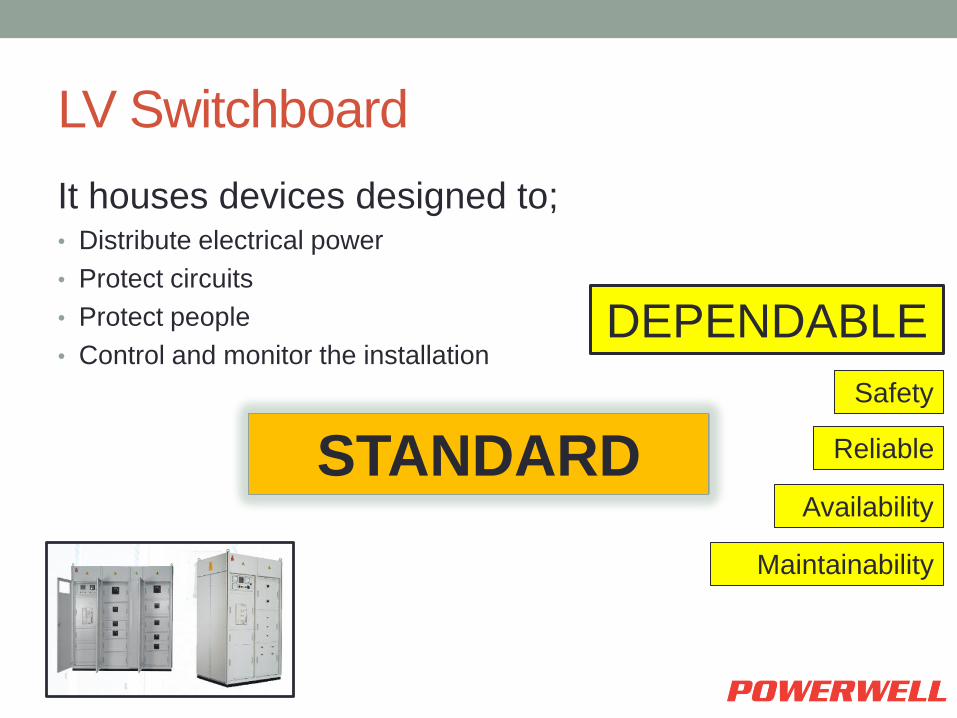
LV Switchboard
It houses devices designed to; • Distribute electrical power
• Protect circuits
• Protect people
• Control and monitor the installation
DEPENDABLE
Safety
Reliable
Availability
Maintainability
STANDARD

Standard body
• International Electrotechnical
Commission (IEC) • All the major industrialized countries are
involved
• Adopted directly into national specifications and
standards
Standard
• Switchboard design refers to Standards
governing the entire low voltage domain, and
more specifically to standards relating to
assemblies.
• Compliance with standards is the minimum
guarantee of a level of quality and dependability.
IEC 61439-1 & IEC 60439-2 STANDARD PARTS COMPARE
How the standard parts compare
• IEC 60439
• Part 1: Type Tested and Partially type tested Assemblies
• Part 2: Busbar trunking systems
• Part 3: Distribution boards
• Part 4: Assemblies for Construction Sites
• Part 5: Assemblies for power distribution

How the standard parts compare
• IEC 61439
• Part 1: General Rules
• Part 2: PSC – Assemblies
• Part 3: Distribution boards
• Part 4: Assemblies for Construction Sites
• Part 5: Assemblies for power distribution
• Part 6: Busbar trunking systems
• Part 7: Assemblies for use in marinas and similar
locations, camping sites and similar locations, market
squares and other similar external public sites

IEC 61439 – Part 1: 2011
General Rules Cross referenced by all other parts of the series.
Does not need to be specified, compliance to one of the
other parts of the standard automatically determines its
compliance
IEC 61439 – Part 2
Power Switchgear and Controlgear Assemblies.
“low – voltage switchgear and controlgear
assembly used to distribute and control energy
for all types of loads, intended for industrial,
commercial and similar applications operated by
skilled or instructed persons”

Low voltage switchgear and controlgear
assemblies

• Enclosure • Earth Bar (protective conductor) • Incoming Device
• Air Circuit Breaker (ACB) • Moulded Case Circuit Breaker (MCCB) • Isolator
• Busbars • Main • Distribution
• Outgoing Devices • Moulded Case Circuit Breakers (MCCB) • Fused Isolators • Miniature Circuit Breakers (MCB) • Additional power circuits (for motor control)
• Auxiliary circuits (controls)
IEC 61439 – Part 2 What is an Assembly?

ISOMETRIC VIEW – FULL ENCLOSURE

ISOMETRIC VIEW – WITHOUT DOORS
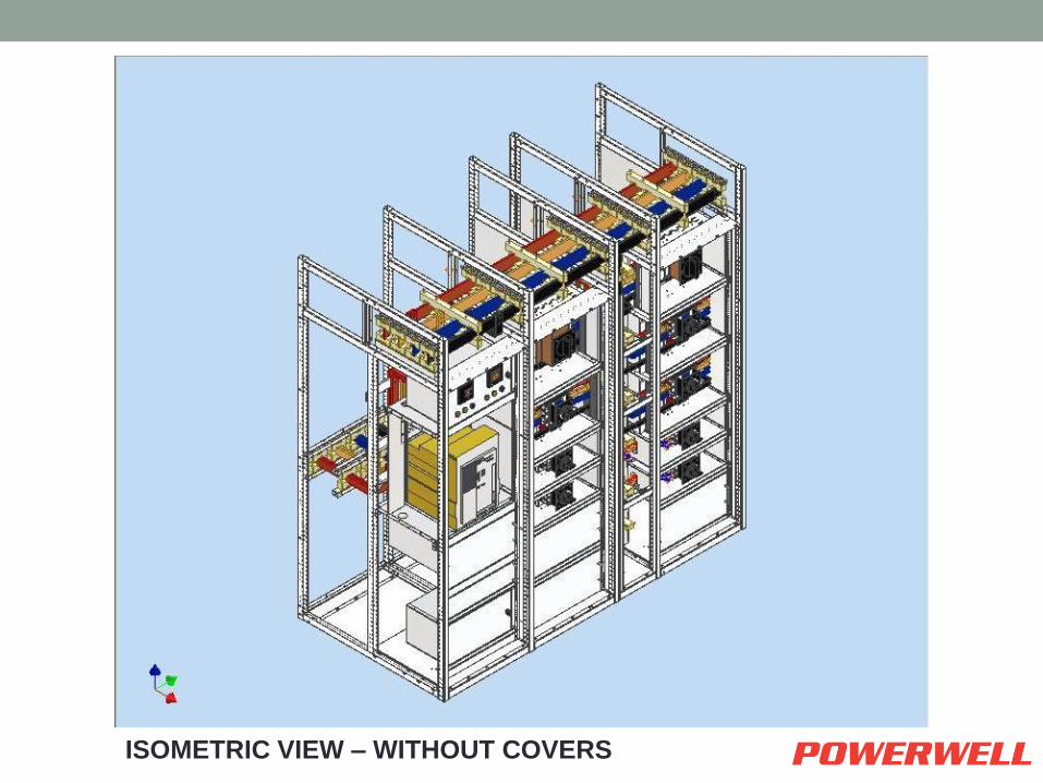
ISOMETRIC VIEW – WITHOUT COVERS
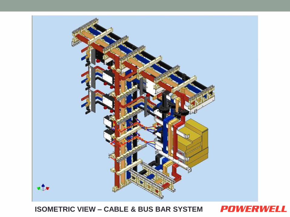
ISOMETRIC VIEW – CABLE & BUS BAR SYSTEM
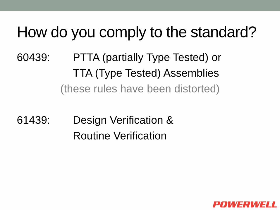
How do you comply to the standard?
60439: PTTA (partially Type Tested) or
TTA (Type Tested) Assemblies
(these rules have been distorted)
61439: Design Verification &
Routine Verification

• The Standard also now recognises that there maybe more than one company responsible for the verification of the final Assembly.
– Original Manufacturer
– Assembly Manufacturer
IEC 61439 – Part 2
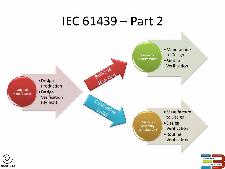
•Design Production
•Design Verification (By Test)
Original Manufacturer
•Manufacture to Design
•Design Verification
•Routine Verification
Original & Assembly
Manufacturer
•Manufacture to Design
•Routine Verification
Assembly Manufacturer
IEC 61439 – Part 2

How do you achieve Design Verification?
• Verification by test
• Verification by Comparison with a reference design
• Verification by Assessment
Not all characteristics can be verified by each of the above
in all circumstances.
Refer Table D. 1
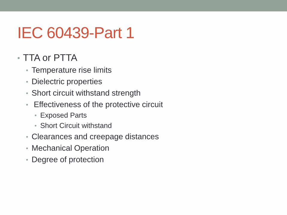
IEC 60439-Part 1
• TTA or PTTA
• Temperature rise limits
• Dielectric properties
• Short circuit withstand strength
• Effectiveness of the protective circuit
• Exposed Parts
• Short Circuit withstand
• Clearances and creepage distances
• Mechanical Operation
• Degree of protection

IEC 61439-Part 2 Construction
• Strength of materials and parts (clause 10.2)
• Degree of protection of enclosures (clause 10.3)
• Clearances and creepage distances (clause 10.4)
• Protection against electric shock and integrity of protective circuits (clause 10.5)
• Incorporation of switching devices and components (clause 10.6)
• Internal electrical circuits and connections (clause 10.7)
• Terminals for external conductors (clause 10.8)
Performance
• Dielectric properties (clause 10.9)
• Temperature rise limits (clause 10.10)
• Short circuit withstand strength (clause 10.11)
• Electromagnetic compatibility (clause 10.12)
• Mechanical Operation (clause 10.13)
Design
Verification
characteristics
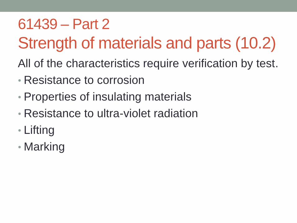
61439 – Part 2
Strength of materials and parts (10.2) All of the characteristics require verification by test.
• Resistance to corrosion
• Properties of insulating materials
• Resistance to ultra-violet radiation
• Lifting
• Marking

61439 – Part 2
Strength of materials and parts (10.2) • Resistance to corrosion
• Ferrous enclosures and internal components of indoor and outdoor
assemblies upon which mechanical operation may depend.
• Resistance to ultra-violet radiation • If manufactured from / coated in synthetic material and for installation
outdoors
• Lifting
• Marking
• Properties of insulating materials • Verification of thermal stability of enclosures
• Only relevant to enclosures or technically significant
external parts manufactured of insulating material.
61439 – Part 2
Strength of materials and parts (10.2) • Properties of insulating materials
• Verification of resistance of insulating materials to normal heat
• Parts that support conductors
• Other parts
• Verification of resistance of insulating materials to abnormal heat
and fire due to internal electric effects
• Parts that support conductors
• Other parts
Note: Verification for normal heat has been removed as a test in
Edition 2
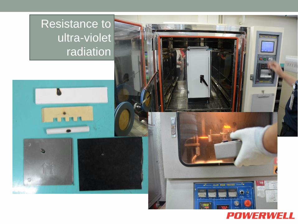
Resistance to
ultra-violet
radiation

Degree of protection of enclosures IEC 60529
• The IP (Ingress Protection) is broken down to
2 elements
• IP XX – Protection against Solid Objects
• IP XX - Protection against water ingress
Default arrangement (minimum): Indoor IP2X; Outdoor
IP23

Degree of protection IEC 60529
• IP XX – Protection against Solid Objects
• IP 2X – 12.5 mm Probe
• IP 3X – 2.5 mm Probe
• IP 4X – 1mm Probe
• IP 5X – Dust (no pressure) – 8 hours
• IP 6X – Dust (negative pressure) – 8 hours
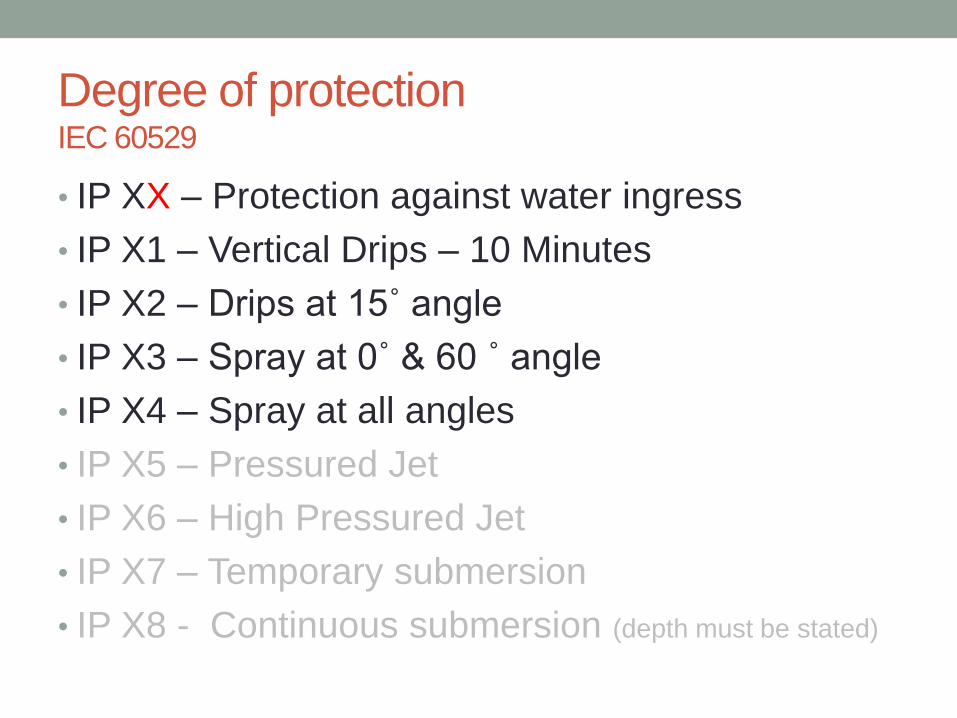
Degree of protection IEC 60529
• IP XX – Protection against water ingress
• IP X1 – Vertical Drips – 10 Minutes
• IP X2 – Drips at 15˚ angle
• IP X3 – Spray at 0˚ & 60 ˚ angle
• IP X4 – Spray at all angles
• IP X5 – Pressured Jet
• IP X6 – High Pressured Jet
• IP X7 – Temporary submersion
• IP X8 - Continuous submersion (depth must be stated)


Internal Separation of PSC – Assemblies
• IEC 61439 clarifies that there is a difference
between Constructional Requirements and
internal separation.
Form of separation does not specify the construction
• If each functional unit is to be contained in its
own compartment – That is what should be
stated.

61439 – Part 2 Clearances and Creepage distances (10.4)
• Clearance:
• The distance from a live conductor to
another live conductor or earth through air.
• Creepage:
• The distance over the surface of insulating
material from a live conductor to another live
conductor or earth

Clearances and Creepage distance

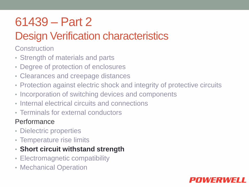
61439 – Part 2 Design Verification characteristics Construction
• Strength of materials and parts
• Degree of protection of enclosures
• Clearances and creepage distances
• Protection against electric shock and integrity of protective circuits
• Incorporation of switching devices and components
• Internal electrical circuits and connections
• Terminals for external conductors
Performance
• Dielectric properties
• Temperature rise limits
• Short circuit withstand strength
• Electromagnetic compatibility
• Mechanical Operation

61439 – Part 2 Protection against electric shock and integrity of
protective circuits (10.5)
• Protection against consequences of a fault within the
assembly
• Resistance Measurement
• Protection against consequences of faults in external
circuits supplied through the assembly
• Short circuit withstand verification

Verification of Effectiveness of
Protective Circuit
61439 – Part 2 Incorporation of switching devices and components
(10.6)
• Selection
• To Suit the assemblies application
• Installation
• To be installed in accordance with the manufacturers instructions
• Not to impair their proper function
• Accessibility
• Adjusting & resetting shall be easily accessible
• Consideration of adjacent functional units
• Not too low or too high
61439 – Part 2 Internal electrical circuits and connections (10.7)
• Main Circuits
• Suitable for short circuit
• Busbars
• connections
• Neutral conductor size
• Auxiliary Circuits
• Bare & Insulated conductors
• Suitable for Temperature rise
• Suitable for Insulation voltage

61439 – Part 2
Terminals for external conductors (10.8) • Suitability of connection of external conductor
• Type of material – Copper / Aluminium / Both
• Size of external conductor
• Size of cable access
• Enables correct cable installation
• Marking

61439 – Part 2 Design Verification characteristics Construction
• Strength of materials and parts
• Degree of protection of enclosures
• Clearances and creepage distances
• Protection against electric shock and integrity of protective circuits
• Incorporation of switching devices and components
• Internal electrical circuits and connections
• Terminals for external conductors
Performance
• Dielectric properties
• Temperature rise limits
• Short circuit withstand strength
• Electromagnetic compatibility
• Mechanical Operation

61439 – Part 2
Dielectric Properties (10.9)
• Power Frequency • Assesses the insulation resistance
• Impulse • Assesses the ability to the assembly to cope with a
voltage spike
• Manufacturer to define kV
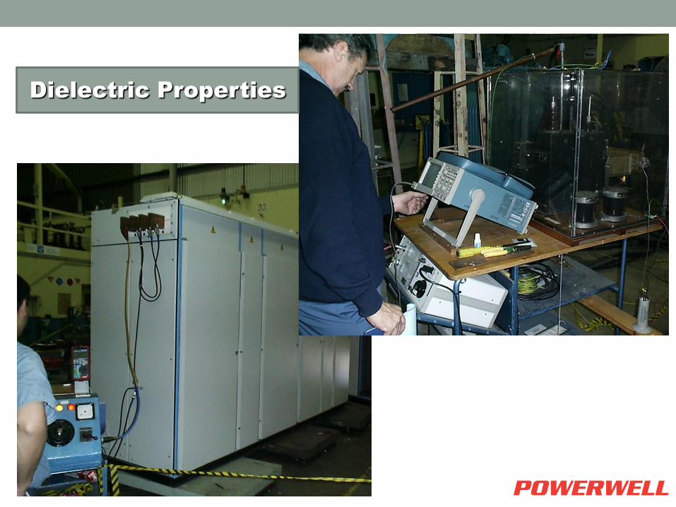
Dielectric Properties

61439 – Part 2 Design Verification characteristics Construction
• Strength of materials and parts
• Degree of protection of enclosures
• Clearances and creepage distances
• Protection against electric shock and integrity of protective circuits
• Incorporation of switching devices and components
• Internal electrical circuits and connections
• Terminals for external conductors
Performance
• Dielectric properties
• Temperature rise limits
• Short circuit withstand strength
• Electromagnetic compatibility
• Mechanical Operation

Temperature Rise
Limits that effect the ratings are:
• Built in Components • Busbars and conductors, Plug-in contacts of
removable or withdrawable parts which connect to busbars
• Discrete arrangements of plug and socket type connections

Temperature Rise Limits
• Maximum Ambient Temperature • 40 Degrees ˚C • 50 Degrees ˚C
• Maximum Working Temperature Maximum Working Temperature – Maximum Ambient Temperature = Temperature Rise
135 ˚C - 50 ˚C = 85 K (˚C)
• The temperature measured and considered is the rise that is achieved after stabilisation (<1K in 1 Hour)
level of rise is stated in K (Kelvin) 1K = 1˚C
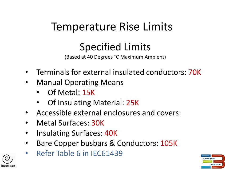
Temperature Rise Limits
Specified Limits (Based at 40 Degrees ˚C Maximum Ambient)
• Terminals for external insulated conductors: 70K • Manual Operating Means
• Of Metal: 15K • Of Insulating Material: 25K
• Accessible external enclosures and covers: • Metal Surfaces: 30K • Insulating Surfaces: 40K • Bare Copper busbars & Conductors: 105K • Refer Table 6 in IEC61439
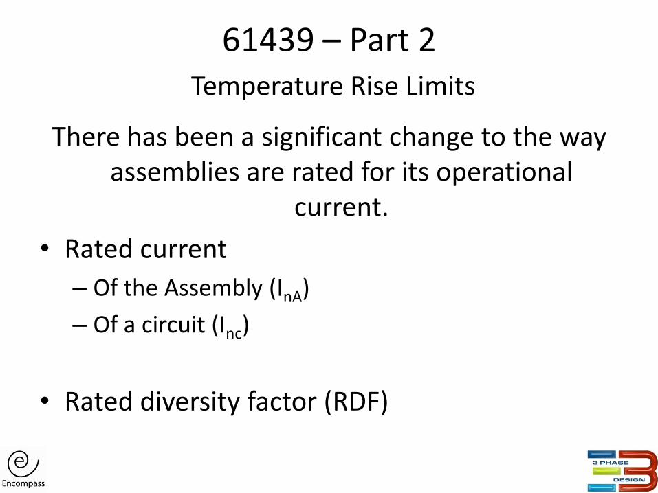
61439 – Part 2 Temperature Rise Limits
There has been a significant change to the way assemblies are rated for its operational
current.
• Rated current
– Of the Assembly (InA)
– Of a circuit (Inc)
• Rated diversity factor (RDF)
61439 – Part 2 Design Verification characteristics Construction
• Strength of materials and parts
• Degree of protection of enclosures
• Clearances and creepage distances
• Protection against electric shock and integrity of protective circuits
• Incorporation of switching devices and components
• Internal electrical circuits and connections
• Terminals for external conductors
Performance
• Dielectric properties
• Temperature rise limits
• Short circuit withstand strength
• Electromagnetic compatibility
• Mechanical Operation
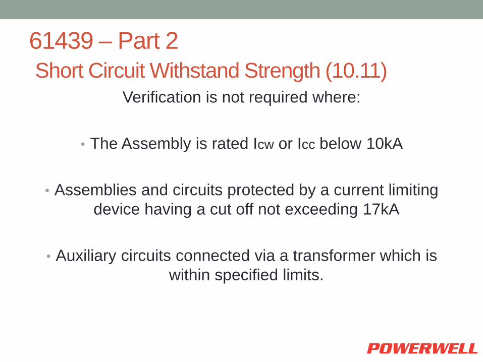
61439 – Part 2
Short Circuit Withstand Strength (10.11) Verification is not required where:
• The Assembly is rated Icw or Icc below 10kA
• Assemblies and circuits protected by a current limiting
device having a cut off not exceeding 17kA
• Auxiliary circuits connected via a transformer which is
within specified limits.

61439 – Part 2
Short Circuit Withstand Strength (10.11)
Busbars, incoming device &
outgoing devices
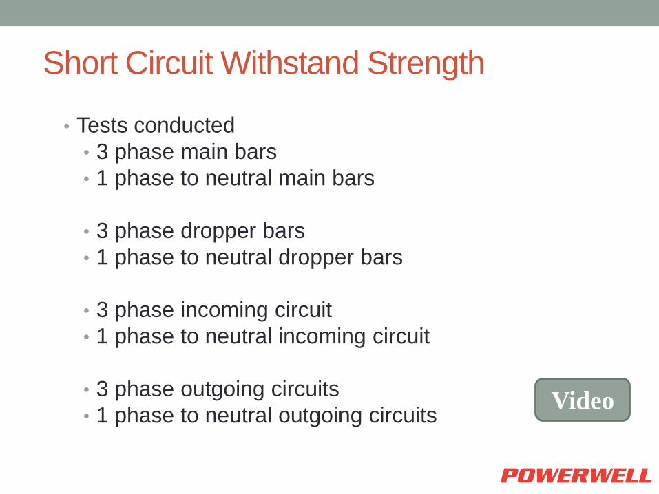
Short Circuit Withstand Strength
• Tests conducted
• 3 phase main bars
• 1 phase to neutral main bars
• 3 phase dropper bars
• 1 phase to neutral dropper bars
• 3 phase incoming circuit
• 1 phase to neutral incoming circuit
• 3 phase outgoing circuits
• 1 phase to neutral outgoing circuits
Video

FRONT VIEW – WITHOUT COVERS

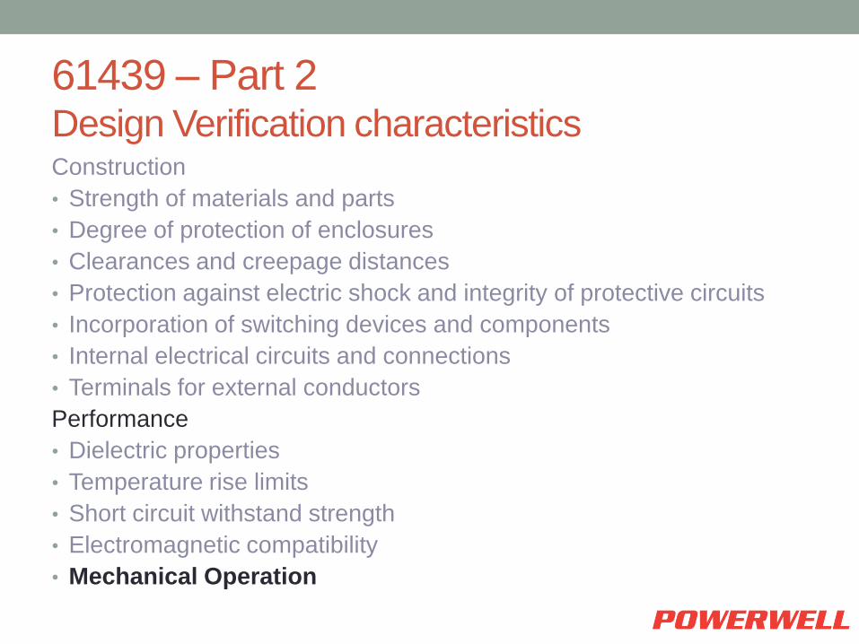
61439 – Part 2 Design Verification characteristics Construction
• Strength of materials and parts
• Degree of protection of enclosures
• Clearances and creepage distances
• Protection against electric shock and integrity of protective circuits
• Incorporation of switching devices and components
• Internal electrical circuits and connections
• Terminals for external conductors
Performance
• Dielectric properties
• Temperature rise limits
• Short circuit withstand strength
• Electromagnetic compatibility
• Mechanical Operation

61439 – Part 2 Routine Verification
Design Verification
Performed on representative samples and designs
Routine Verification
Performed on every supplied assembly – by checking against Design Verification
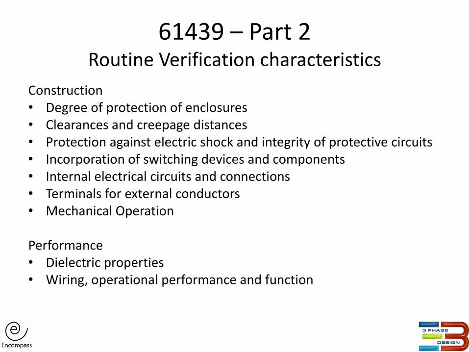
61439 – Part 2 Routine Verification characteristics
Construction • Degree of protection of enclosures • Clearances and creepage distances • Protection against electric shock and integrity of protective circuits • Incorporation of switching devices and components • Internal electrical circuits and connections • Terminals for external conductors • Mechanical Operation
Performance • Dielectric properties • Wiring, operational performance and function

IEC 61439 – Parts 1 & 2 To Summarise
PTTA & TTA replaced by design verification Original and Assembly manufacturer recognised Clarity provided in where design rules and calculation can be used Clarification in the form of separation New tests required on enclosure Changes in the temperature rise test procedure Routine verification improved to cross reference design verification
IEC 61641: 2008 ARCING DUE TO INTERNAL FAULT

IEC 61641 Arcing due to internal fault
• Possible cause of electrical arcs
• Arc due to dielectric breakdown
• Introduction of foreign object
• Faulty connection
• Pressurised ionised gases
Video Video

Arcing Fault Containment Test
Fail

Pass
Arcing Fault Containment Test

Before After
Arcing Fault Containment Test

IEC 61641 Arcing due to internal fault
• Load side of the outgoing functional unit
• Supply side of the outgoing functional unit
• Along the distribution busbar
• Along the main busbar
• Load side of the incoming functional unit
• Supply side of the incoming functional unit
Arcing due to internal fault
The Purpose
• To verify the effectiveness of the construction of
Form Separation for the Assembly
• To assess the ability of the Assembly to limit the
risk of personal injury resulting from an internal
Arcing Fault.
• Dielectric tests were performed after the Arcing
Fault Test.

Arcing due to internal fault
The Assessment of Test Results
• All covers, doors and fastenings were intact
• No components were dislodged
• The cotton gauze did not ignite &
damages were confined to that unit,
• Proof of minimum risk of personal injury
• Busbar and all other functional units remain firm
for further service.
QUESTION & ANSWER

Question and answer
• When short circuit occurred to the LV switchboard,
can the switchboard be operated again? Why?
• When an arc occurred at the LV switchboard, can
the switchboard be operated again? Why?
• Why Form 4B and arc fault containment for your
project?