low earth orbit environmental effects on the space station ... · low earth orbit environmental...
TRANSCRIPT

7 m
NASA Technical Memorandum 100230
Low Earth Orbit Environmental Effects on the Space Station Photovoltaic Power Generation Systems [NASA-Tfi-100238) LOW EAPTH O R B I T N88-? 2429
E I V I R O N M E N T A L EFFECTS ON THE SPACE STATION PHOTOVOLTAIC POWER G Z N E R B T I O N SYSTERS (NASA) 20 p Avai l : NTXS HC Af'3/PlF A01 . n n c l a s
CSCL 10A 6 3 / 8 8 0107323
Prepared for the 1988 Solar EbRlrgy C m sponsored by the Ammeai * society& Engineers Golden, Colorado, A& I(J-14, 1988
https://ntrs.nasa.gov/search.jsp?R=19880003047 2018-06-06T09:44:59+00:00Z

LOW EARTH ORBIT ENVIRONMENTAL EFFECTS ON THE SPACE STATION
PHOTOVOLTAIC POWER GENERATION SYSTEMS
Henry K . Nahra Nat iona l Aeronaut ics and Space A d m i n i s t r a t i o n
Lewis Research Center Cleveland, Ohio 44135
SUMMARY
A summary o f the Low Ear th o r b i t a l Environment, i t s impact on the Photo- v o l t a i c Power systems o f the Space S t a t i o n and the s o l u t i o n s implemented t o r e s o l v e t h e environmental concerns or issues are descr ibed i n t h i s paper. Low Ear th O r b i t a l environment (LEO), presents several concerns to the P h o t o v o l t a i c Power systems o f the Space S t a t i o n . These concerns i nc lude atomic oxygen
L n a3 i n t e r a c t i o n w i t h the po lymer ic subs t ra te o f the s o l a r a r rays , i o n i z e d env i ron- r*) I
ment e f f e c t s on the a r r a y opera t i ng vo l tage, the e f f e c t s of the meteoroids and w d e b r i s impacts and p e n e t r a t i o n through the d i f f e r e n t l a y e r s of the s o l a r c e l l s
and t h e i r c i r c u i t s , and the h igh energy p a r t i c l e and r a d i a t i o n e f f e c t s on the o v e r a l l s o l a r a r r a y performance.
(v
P o t e n t i a l s o l u t i o n s to some of the degrading environmental i n t e r a c t i o n s t h a t w i l l p rov ide the p h o t o v o l t a i c power systems of the Space S t a t i o n w i t h the des i red l i f e are a l s o summarized i n t h i s paper.
INTRODUCTION
Design o f spacecra f t for long d u r a t i o n missions for the low e a r t h o r b i t a l environment presents new chal lenges t h a t are the r e s u l t o f concerns over poss i - b l e spacecra f t systems i n t e r a c t i o n s w i t h the environment. The NASA Space Sta- t i o n design i s an u l t i m a t e chal lenge because o f the s i ze , o r b i t , l i f e t i m e , and i n t e r f a c e requirements imposed on the var ious system designers.
The Pho tovo l ta i c Power Generation system o f the Space S t a t i o n I n t e r a c t s w i t h the environment i n a v a r i e t y o f ways. from the power system moving through the LEO i o n i z e d environment whereas chemi- c a l i n t e r a c t i o n i s p r i m a r i l y represented by the o x i d a t i o n o f the power system po lymer ic m a t e r i a l s by atomic oxygen which represent the main chemical c o n s t i t- uent o f the LEO environment. Physical i n t e r a c t i o n r e s u l t s from the e f f e c t o f atmospheric drag and impact of the meteoroids and o r b i t a l d e b r i s on the Space S t a t i o n power system surfaces. The drag e f fec t , which causes the o r b i t a l decay and which can be compensated for by the reboost p lans and manouvers i s beyond the scope of t h i s paper and there fore w i l l n o t be discussed. However, meteor- o i d and o r b i t a l deb r i s i n t e r a c t i o n and ef fects on the PV power system are d e t a i l e d i n t h i s paper.
E l e c t r i c a l i n t e r a c t i o n r e s u l t s
This paper fu rn i shes a b r i e f d e s c r i p t i o n o f the P h o t o v o l t a i c (PV) power genera t i on system, i t s chemical, e l e c t r i c a l , and phys i ca l i n t e r a c t i o n s w i t h the environment, and the approaches taken t o reso lve or implement the env i ron- mental concerns i n the power system design.

DEFINITION AND DESCRIPTION OF THE PV POWER MODULE
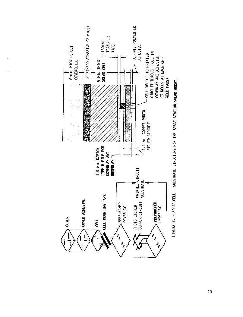
The Photovoltaic power system of the Space Station comprises two PV power modules that generate 37.5 KW to the users. figure 1 , consists of two solar arrays for DC power generation, batteries for energy storage, a thermal control system for the thermal conditioning o f bat- teries and frequency conversion devices, two rotational joints for solar point- ing, and the truss for structural support. mechanical and structural design resembles the design of the flexible, deploya- ble-retractable solar array flown on board of the Solar Array Flight Experi- ment (SAFE) (ref. 1). The solar array, as illustrated in figure 2, comprises two blankets which are made of hinged panels for power generation, a mast for deployment and retraction of the array, a canister, and a blanket box for mast and blanket stowage. The panel substrate is made of two prepunched polyimide Kaptonl sheets that are laminated by a polyester adhesive. that i s print etched o n one of the Kapton sheets prior to lamination provides the electrical connection between cells. Solar cell/circuit contact is achieved by welding the wrap-through interconnect cells to the copper pads ap- pearing through the Kapton prepunched holes. cell-substrate structure.
The PV module as shown in
The Space Station (SS) solar array
A copper circuit
Figure 3 illustrates the
DESCRIPTION OF THE LEO ENVIRONMENT
The LEO environment can be summarized to include t h e neutral and ionized gaseous environment, the radiation and meteoroids, and debris environment. These environments are not physically separated in space and time. coexist and their effect can be synergistic in nature.
They
Atomic Oxygen
The neutral environment consists o f residual gases ith concentration strongly dependent on altitude and solar activity. atomic oxygen is highest in concentration compared to other neutrals (ref. 2) in the LEO orbital altitudes. todissociation of molecular oxygen in the vacuum UV region (100 < X < 200 nm) as given by (ref. 2)
As depicted in figure 4,
Atomic oxygen i s construed to be created by pho-
02 + hv * 0. + 0.
Atomic oxygen i s a highly reactive species. oxygen result in different reaction products. layers o f metal oxides whereas polymers experience mass loss and develop a tex- tured surface.
Reaction of materials with atomic In general, metals develop
Charged Part i cl es
The ionized or plasma environment constituents are ions and electrons of concentrations dependent on the solar activity, position, and time. This envi- ronment i n near equatorial orbits causes charges t o collect on power surfaces
lRegistered trademark o f E.I. Dupont de Nemours and Co., Inc.
2

and form p a r a s i t i c cu r ren ts . Moreover, a r c i n g between the s o l a r a r r a y and the plasma rep resen t another p o t e n t i a l i n t e r a c t i o n t h a t may occur depending on the o p e r a t i n g vo l tage of t he a r r a y ( r e f . 3 ) .
High energy p e n e t r a t i n g charged p a r t i c l e s which e x i s t i n the geosynchro- nous and LEO p o l a r o r b i t s o r i g i n a t e from the magnetosphere and cosmic rays. Magnetospheric p a r t i c l e s c o n s i s t p r i m a r i l y o f e lec t rons o f 10's o f KeV and pro- tons o f M e V ' s i n energy which are t rapped i n the magnetosphere due t o the mag- n e t i c f i e l d e f f e c t . The charged energe t i c p a r t i c l e s o s c i l l a t e between the two hemispheres and form the Van A l l e n b e l t s which f o l l o w the magnetic f i e l d l i n e s . Energet ic p ro ton and e l e c t r o n f l u x e s impact ing the s o l a r a r rays degrade the s o l a r c e l l s and a r r a y performance ( r e f . 3 ) . Th is degradat ion e f f e c t i s i nc lud - ed as an o v e r s i z i n g parameter i n the design o f the s o l a r a r ray .
Aurora l ene rge t i c p a r t i c l e f l u x e s occur i n the au ro ra l zones due t o the h ighe r magnetic f i e l d f l u x e s . A t LEO a l t i t u d e s , au ro ra l protons and e l e c t r o n f l u x e s , a l though n o t pene t ra t i ng , induce charg ing o f m e t a l l i c and d i e l e c t r i c sur faces and thereby produce p o t e n t i a l d i f f e r e n c e s between those charged sur- faces ( r e f . 3 ) .
Cosmic rays , de f ined as protons, e lec t rons , and n u c l e i of a l l elements, a r i s e from g a l a c t i c and s o l a r o r i g i n s and are considered I s o t r o p i c ou ts ide the magnetosphere. magnetic f i e l d of the ea r th . Al though the e f fec t o f cosmic rays on the power system m a t e r i a l s i s minimal, g a l a c t i c cosmic rays may induce performance upset 1 n m i c r o e l e c t r o n i c devices. the charg ing e f f e c t s o f the magnetospheric au ro ra l charged p a r t i c l e s ( r e f . 3 ) .
Depending on t h e i r energy, cosmic rays a re d e f l e c t e d by the
Moreover, s o l a r cosmi c rays protons may enhance
Radi a t i on
Elect romagnet ic r a d i a t i o n environment cons is t s o f the s o l a r spectrum ( f i g . 5) which peaks i n the v i s i b l e reg ion , and from the r a d i a t i o n emi t ted from p a r t i c l e s and f i e l d i n t e r a c t i o n s . t he spectrum o f wavelength l ess than 200 nm possesses low i n t e n s i t y , photons from t h i s r e g i o n have s u f f i c i e n t energy t o break polymer ic bonds and degrade the backbone cha in s t r u c t u r e o f the o rgan ic space polymer ( r e f . 4 ) .
Even though the u l t r a v i o l e t reg ion o f
Meteoroids and Debr is
Meteoroids and space debr i s represent the p a r t i c u l a t e environment i n LEO. 20 km/s and average d e n s i t y o f 0.5 g/cm . Space debr i s , de f ined as man made p a r t i c l e s o r b i t the e a r t h w i t h an average v e l o c i t y o f 10 km/s and an average d e n s i t y o f 2.7 g/cm3 ( r e f . 5).
Meteoro id streams impact f rom dee! space w i t h an average v e l o c i t y of
Impact o f a meteoroid or space debr i s can cause pene t ra t i on i n the sur- face . Pene t ra t i on through a s o l a r c e l l g ives r i s e t o l o c a l damaged area and reduces the power ou tpu t o f the c e l l . Pene t ra t i on through the subs t ra te may open a s t r i n g c i r c u i t and d i sab le the s t r i n g o f c e l l s . and degree o f redundancy, pene t ra t i on through a r a d i a t o r panel can degrade the performance of the r a d i a t o r i f the p r o b a b i l i t y o f impact was never taken i n t o account i n the des ign phase.
Depending on i t s design
3
PHOTOVOLTAIC POWER MODULE CHEMICAL INTERACTION WITH LEO ENVIRONMENT
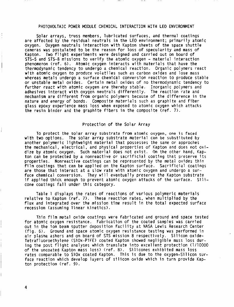
Solar ar rays, t r u s s members, l u b r i c a t e d sur faces, and thermal coat ings are a f f e c t e d by the r e s i d u a l n e u t r a l s i n t h e LEO environment; p r i m a r i l y atomic oxygen. Oxygen n e u t r a l s i n t e r a c t i o n w i t h Kapton sheets of the space s h u t t l e cameras was p o s t u l a t e d t o be t h e reason for l o s s o f s p e c u l a r i t y and mass o f Kapton. Two f l i g h t exper iments w e r e designed and c a r r i e d o u t on board o f STS-5 and STS-8 miss ions t o v e r i f y the atomic oxygen - m a t e r i a l i n t e r a c t i o n phenomenon ( r e f . 6). Atomic oxygen i n t e r a c t s w i t h m a t e r i a l s t h a t have the thermodynamic tendency t o undergo a chemical r e a c t i o n . Organic polymers r e a c t w i t h atomic oxygen to produce v o l a t i l e s such as carbon ox ides and lose mass whereas meta ls undergo a sur face chemical convers ion r e a c t i o n t o produce s t a b l e or uns tab le metal ox ides. C e r t a i n metal ox ides o f no thermodynamic tendency t o f u r t h e r r e a c t w i t h atomic oxygen are thereby s t a b l e . adhesives i n t e r a c t w i t h oxygen n e u t r a l s d i f f e r e n t l y . The r e a c t i o n r a t e and mechanism are d i f f e r e n t from o r g a n i c polymers because o f t h e d i f f e r e n c e i n the n a t u r e and energy o f bonds. Composite m a t e r i a l s such as g r a p h i t e and f i b e r g lass epoxy exper ience mass l o s s when exposed t o atomic oxygen which a t tacks the r e s i n b inder and t h e g r a p h i t e f i b e r s i n t h e composite ( r e f . 7).
I n o r g a n i c polymers and
P r o t e c t i o n o f t h e So lar Ar ray
To p r o t e c t the s o l a r a r r a y s u b s t r a t e from atomic oxygen, one i s faced w i t h two o p t i o n s . The s o l a r a r r a y s u b s t r a t e m a t e r i a l can be s u b s t i t u t e d by another po lymer ic l i g h t w e i g h t m a t e r i a l t h a t possesses the same or approches the mechanical, e l e c t r i c a l , and p h y s i c a l p r o p e r t i e s o f Kapton and does no t oxi- d i z e by atomic oxygen. Such m a t e r i a l does n o t e x i s t . On t h e o t h e r hand, Kap- t o n can be p r o t e c t e d by a nonreac t ive or s a c r i f i c i a l c o a t i n g t h a t preserve i t s p r o p e r t i e s . Nonreact ive coat ings can be represented by the metal ox ides t h i n f i l m coa t ings t h a t can be a p p l i e d on t h e Kapton surface. S a c r i f i c i a l coa t ings are those t h a t i n t e r a c t a t a s low r a t e w i t h atomic oxygen and undergo a sur- face chemical conversion. They w i 1 1 eventual l y preserve t h e Kapton subs t ra te i f a p p l i e d t h i c k enough t o prevent atomic oxygen a t t a c k s o f the sur face. cone coat ings f a l l under t h i s category.
Table 1 d i s p l a y s t h e r a t e s of r e a c t i o n s of v a r i o u s polymer ic m a t e r i a l s r e l a t i v e t o Kapton ( r e f . 7 ) . These r e a c t i o n r a t e s , when m u l t i p l i e d by the f l u x and i n t e g r a t e d over the miss ion t ime r e s u l t i n t h e t o t a l expected sur face recess ion (assuming l i n e a r k i n e t i c s ) .
S i l i -
Th in f i l m metal o x i d e coat ings were f a b r cated and ground and space t e s t e d for atomic oxygen r e s i s t a n c e . F a b r i c a t i o n o f the coated samples was c a r r i e d o u t i n the i o n beam s p u t t e r d e p o s i t i o n f a c i l i y a t NASA Lewis Research Center ( f i g . 6). Ground and space atomic oxygen r e s stance t e s t i n g was performed i n a i r plasma ashers and on board o f STS miss ion 8 r e s p e c t i v e l y . S i l i c o n ox ide- T e t r a f l u o r o e t h y l e n e (S iOx-PTFE) coated Kapton showed n e g l i g i b l e mass loss dur- i n g the p o s t f l i g h t analyses which t r a n s l a t e i n t o e x c e l l e n t p r o t e c t i o n (1/10000 o f the uncoated Kapton mass loss) ( r e f . 8 ) . S i l i c o n e s e x h i b i t e d mass l o s s r a t e s comparable t o S i O x coated Kapton. This i s due t o the oxygen-Si l icon sur- face r e a c t i o n which develop l a y e r s o f s i l i c o n o x i d e which i n t u r n p rov ide Kap- ton p r o t e c t i o n ( r e f . 9).
4

Several NASA programs are designed to support manufactur ing a durab le s o l a r a r r a y t h a t su rv i ve the LEO environment. NASA Lewis i s designed t o screen p o t e n t i a l coa t ings for o x i d a t i o n res i s tance , f l e x i b i l i t y , res i s tance to process ing chemicals, and UV environment e f f e c t s . A f t e r exposure t o s imulated atomic oxygen and UV environment, t he c o a t i n g dura- b i l i t y i s f u r t h e r evaluated us ing surface a n a l y s i s techniques such as Ruther- f o r d backsca t te r i ng spect rometry ( R B S ) , Elec t ron Spectroscopy and Chemical Ana lys is (ESCA), Auger Spectroscopy, and Scanning E l e c t r o n and Transmission Microscopy.
The in-house t e s t i n g program a t
The Space S t a t i o n P r o t e c t i v e Coat ings Development program, managed by Mar- s h a l l Space Center, i s t o develop p r o t e c t i v e coat ings for the Space S t a t i o n vu lnerab le surfaces. Considerable efforts were inves ted i n i no rgan ic coat ings c h a r a c t e r i z a t i o n and t e s t i n g i n atomic oxygen and UV environment f o r the s o l a r a r r a y subs t ra te . S i l i c o n e polymer ic coat ings , as r e s u l t of the aforement ioned t e s t i n g , proved to be the most r e s i s t a n t t o atomic oxygen ( r e f . 10).
The o b j e c t i v e o f the Pho tovo l ta i c Array Environmental P r o t e c t i o n program
This program w i 11 produce p ro tec ted and durable s o l a r a r r a y panel s t h a t
(PAEP), as managed by NASA Lewis, i s to implement the promis ing p r o t e c t i v e coat ings such as metal ox ides and s i l i c o n e s i n t o the a r r a y manufactur ing proc- ess. achieve the l i f e t i m e requirements o f the s o l a r a r r a y o f 15 years i n o r b i t ( r e f . 11) .
Atom1 c oxygen degrades the epoxy b i nder i n S-glass compos i t e epoxy whi ch c o n s t i t u t e the s t r u c t u r a l m a t e r i a l from which the s o l a r a r r a y mast i s made. The g lass f i b e r s m a t r i x as a r e s u l t may d i s i n t e g r a t e (from f i b e r r u p t u r e ) and consequent ly, t h i s in t roduces degradat ion i n mechan’cal and phys i ca l p r o p e r t i e s o f the S-glass epoxy composite. The PAEP program w i l l s tudy and implement pro- t e c t i o n schemes for the s o l a r a r r a y mast s t r u c t u r a l members aga ins t atomic oxy- gen a t tack .
S t r u c t u r e P r o t e c t i o n
Unprotected g r a p h i t e epoxy t r u s s members degrade a t the same r a t e as unprotected Kapton as demonstrated i n the s h u t t l e exper iments. As p r e v i o u s l y mentioned, t h i s degradat ion i s due t o the g r a p h i t e f i b e r s and epoxy b inde r r e - a c t i n g w i t h atomic oxygen. Such degradat ion r e s u l t s i n mass l o s s and d e t e r i o - r a t i o n i n the mechanical p r o p e r t i e s of the g r a p h i t e epoxy. Efforts a re o r i e n t - ed toward p r o t e c t i n g the t r u s s tubes us ing p r o t e c t i v e l a y e r s o f aluminum which can be app l i ed us ing the c o a t i n g technology or adhesive bonding technology. An impor tan t i ssue i n manufactur ing the p ro tec ted tubes i s the mismatch i n the c o e f f i c i e n t o f thermal expansion (CTE). The o b j e c t i v e i s t o min imize the m i s - match i n o rde r t o reduce mic rocrack ing a t the aluminum/composite i n t e r f a c e ( r e f . 12) .
Johnson Space Center and Langley Research Center a re a c t i v e l y i nvo l ved i n efforts to manufacture durab le t r u s s members t h a t a re s t a b l e i n atomic oxygen and thermal c y c l i n g environment. Several programs e x i s t e d and cont inue to e x i s t to the rma l l y cyc le d i f f e r e n t p r o t e c t i o n schemes and mon i to r the mechani- ca l p r o p e r t i e s change as a f u n c t i o n of the number of cyc les .
5

Lubr ican ts Degradat ion and P r o t e c t i o n
Lubr ican ts are s u b j e c t t o chemical i n t e r a c t i o n w i t h atomic oxygen and UV. Organic po lymer ic l u b r i c a n t s o x i d i z e i n t h e presence o f atomic oxygen t o produce v o l a t i l e carbon ox ides . S i l i c o n e s on the o t h e r hand undergo a chemi- c a l sur face r e a c t i o n t h a t a l t e r the sur face composi t ion, i .e . , develop l a y e r s o f s i l i c o n ox ide which may damage t h e l u b r i c a t e d sur face. Molybdenum d i s u l - f i d e , which i s considered as a p o t e n t i a l space l u b r i c a n t r e a c t s w i t h atomic oxygen to form b r i t t l e molybdenum ox ide and v o l a t i l e s u l f u r ox ide ( r e f . 13). Lubr ican ts t h a t are exposed t o atomic oxygen are s u b j e c t to chemical r e a c t i o n s . However, enclosed l u b r i c a n t s are p r o t e c t e d and thereby expected to exper ience minute degradat ion o f performance.
Thermal Cont ro l Coat ings Degradat ion
Organic and i n o r g a n i c thermal c o n t r o l coa t ings are expected t o r e a c t t o the atomic oxygen and UV environment. A s shown i n f i g u r e 7, the thermal con- t ro l o rgan ic f i l m , most known i n the spacecra f t i n d u s t r i e s as s i l v e r Te f lon , c o n s i s t o f a f l u o r i n a t e d ethy lenepropylene ( F E P ) l a y e r coated w i t h s i l v e r on the unexposed sur face and adhered t o t h e s u b s t r a t e t o be t h e r m a l l y c o n t r o l l e d ( r e f . 14). The FEP l a y e r i s known to r e a c t and exper ience degradat ion i n o p t i - c a l p r o p e r t i e s and mass due t o t h e UV and atomic oxygen e f f e c t s .
An i n o r g a n i c c o a t i n g i s made o f t h r e e main i n g r e d i e n t s : pigment, b inder , and water as a so lvent . The most t h r e e known i n o r g a n i c thermal c o n t r o l coat- ings are 293, S13G/LO and z i n c o r t h o t i t a n a t e . The first (293), c o n s i s t i n g o f a z i n c ox ide pigment and a potassium s i l i c a t e b inder , sCIowed small inc rease i n the s o l a r a b s o r p t i v i t y , as, and no change i n thermal emi t tance, E t , a f t e r extended UV exposure (5000 e q u i v a l e n t sun hours ESH). absorptance and thermal emi t tance of the 293 due t o atomic oxygen i s n o t expected t o be s i g n i f i c a n t because o f the l a c k of atomic oxygen r e a c t i v e mate- r i a l s i n the c o a t i n g s t r u c t u r e . The second c o a t i n g (S13G/LO), which i s made o f z i n c ox ide/potass ium s i 1 i c a t e p igment ib inder and t r e a t e d w i t h s i 1 icone b inder i s expected to degrade i n performance ( inc rease i n as and decrease i n E t ) because o f the a n t i c i p a t e d i n t e r a c t i o n o f the s i l i c o n e b inder w i t h A0 and UV r a d i a t i o n ( r e f . 15). The z i n c o r t h o t i t a n a t e pigment, when t r e a t e d w i t h s i l i c a t e b inder and wa te r so lvent , r e s u l t s i n z i n c o r t h o t i t a n a t e thermal con- t ro l c o a t i n g ( r e f . 16). S i m i l a r t o 293, t h i s p a i n t under UV exposure o f 5000 ESH, e x h i b i t e d l i t t l e increase i n the as ( r e f . 15). I n a d d i t i o n , atomic oxygen e f f e c t s are n o t a n t i c i p a t e d to change t h e s o l a r absorptance and thermal emit tance ( r e f . 16).
Degradat ion o f s o l a r
I t i s wor th n o t i n g t h a t , a l though i n o r g a n i c coat ings a r e n o t g r e a t l y degraded by t h e environment, they have some drawbacks such as b r i t t l e n e s s , poor adherence, and r e q u i r e spec ia l h a n d l i n g and process ing procedures. More- over , thermal c y c l i n g e f f e c t s (which i n t r o d u c e c y c l i c thermal s t resses on the coat ing and r e s u l t i n mic rocrack ing) , and contaminat ion e f f e c t s (which induce deposi ts on the surface and r e s u l t i n changes i n the t h e r m - o p t i c a l p r o p e r t i e s ) are two a d d i t i o n a l e f f e c t s t h a t can p o t e n t i a l l y couple w i t h UV t o follow i n h igher degradat ion.
6

Durable Thermal Control Coatings
Due to the various environmental factors that affect the thermal control coating performance, a new approach was initiated at JSC to develop a high emittance (no less than 0.75) and low solar absorptance (no higher than 0.2 over 10 years lifetime) thermal control coating over an aluminum substrate for the Space Station central radiators. The new approach which i s based on match- ing the CTE's of the coating and substrate uses aluminum conversion coatings. Samples o f anodized aluminum, silicones, and fluorocarbons emitting layers over aluminum substrate were fabricated and tested for 1 imi ted number o f thermal cycles. Future plans include testing and evaluation of sample performance in atomic oxygen, UV, extended thermal cycling, and contamination environments (ref. 17).
PHOTOVOLTAIC POWER MODULE ELECTRICAL INTERACTION WITH LEO ENVIRONMENT
Electrical interaction of the power systems with the environment are described by the plasma interaction phenomena such as parasitic current collec- tion and arcing in equatorial orbital environment, and charging in polar orbi- tal environment.
Electrically biased structures in plasma environment establish a potential distribution such that the total collected ion and electron currents balance. Since the thermal velocities of electrons is significantly higher than the ions, the area of positive potential relative t o the plasma (where electrons are collected) will be smaller than the area of negative potential (where ions are collected) at equilibrium. The solar arrays similarly exhibit a potential distribution. Enhanced current collection (snap-over) i s known t o occur in the positive potential area whereas arcing is known to take place toward the nega- tive potential end of the array (ref. 18).
Current Collection
Collected currents depend on the thermal ion and electron velocities and the plasma sheath wldth. the surface and ambient plasma where electric fields exist. since the array will establish a potential distribution, the plasma sheath thickness which is a function of potential will vary on the conductive surface of the array and so do the collected currents. copper pads and the cell edges are suspected to be collection sites. impact of these current collection sites on the whole solar array performance i s yet to be analytically and experimentally determined in the plasma interac- tion test which will be discussed later. Surfaces of high positive potential relative to the plasma, experience drastically increased electron collection currents because the normal ly insulating surfaces wi 1 1 transport charges 1 ike the conducting surfaces (ref. 19). imentally assessed in the plasma interaction test as well.
The plasma sheath i s defined as the space between
In the present solar array design, only the The
The severity of this effect i s t o be exper-
Arc i ng
Arcing to plasma has been observed t o take place at regions of negative Arcing mechanism is postulated to potentials relative to the plasma ground.
7

be accompanied with electron emisslon and current surges into the plasma (ref. 20). Moreover, arcing is a function of the operating voltage of the array and the plasma condition. A true arcing voltage threshold (which is the voltage below which arcing never occurs) may exist for a specific plasma condi- tion. determined. However, existence of an area of negative potential relative to the plasma, and an insulator/metal geometry have associated to arcing to the plasma (ref. 19).
Conditions for occurence of arcs have not yet been completely
Excessive arcing damages the solar array materials and components such as the solar cells and the substrate. Plasma interaction ground testing results of an array of wrap-around solar cells negatively biased to -600 V and exposed t o argon plasma of 1012/m3 show that the array experienced 2.5 percent power degradation and collected approximately 10 pa over 50 hours (ref. 19). Mate- rial damage follows from the high current densities experienced during arcing and the high energy fluxes that could locally damage the chemical bonding and structure (ref. 21).
Charging
Surface charging follows from the collection of high energy electrons (between 1 and 10 KeV) which exist in the geosynchronous and polar orbits. Collection of highly energetic particles give rise to KeV surface potentials which enhance and cause arcing to plasma, surface contamination, and possible damage of the interconnects. rience such environment the effect of which is yet to be experimentally deter- mined in the plasma interaction test (refs. 18 and 19).
The station polar platform solar arrays may expe-
The solar array plasma interaction test is planned at NASA Lewis to test and verify the operating voltage of the solar array. An active space station solar array panel capable of generating a nominal 80 V will be exposed to the simulated plasma environment. A power supply will be used to bias the panel with the appropriate potential to simulate the orbital nominal potential of 160 V (two panels in series). During testing, collected currents and arcing will be closely monitored. In the same test, energetic electron beams will be used t o simulate the polar plasma charging effects and their impact on arcing rates and currents. The test is planned to be performed during the summer of 1988 at NASA Lewis plasma simulation facility.
PHOTOVOLTAIC POWER MODULE PHYSICAL INTERACTION WITH LEO ENVIRONMENT
As previously mentioned, physical interaction effects are manifested as atmospheric drag effects which are not discussed here and particulate impact on the photovoltaic power surfaces.
Model i ng
Analytical studies of the meteoroid and debris impacts on an orbiting sur- face require a damage model and a f l u x model. The damage model calculates the size of particles that can partially or fully penetrate a surface o f certain thickness, physical , and mechanical properties. The particle size that is cal- culated from the experimentally derived damage model can then be used in the
8

flux equation t o calculate the flux of particles of certain size o r higher that could penetrate o r damage the surface. debris flux models used in the probability impact analysis.
Figure 8 shows the meteoroids and
Impact on Array Performance
Meteoroids and debris only degrade the performance of the PV module; their impact on the solar arrays and the radiator surfaces is not life threatening. Degradation of power output from the solar arrays can be related to texturing o f the coverglass of the solar cells which promote light scattering losses. Penetration of meteoroids and debris through the substrate can open circuit the solar cell string, thereby reducing the power output. These potential losses can be accounted for by oversizing the solar array and increasing the redun- dancy. It is noteworthy that oversizing factors are based on the probability of impact, penetration, and breakage of the circuit which makes the analysis rather conservative.
Impact on Fluid Lines
The impact of a particle and its penetration in a fluid line can break the fluid loop in the thermal system. If the fluid loop is redundant, this leaves the thermal system with one operational fluid loop the failure of which result in the inability of the thermal control system to control the temperature of the batteries and the power management and distribution equipment. T o account for such an effect, probability of impact and penetration, and fluid lines bumpering analyses are performed to optimize the bumper thickness and spacing as function of weight and reliability requirements.
Impact on Radiator Performance
In a heat pipe radiator, penetration of a particle through the heat pipe disables only the impacted panel and reduces the overall performance of the radiator. To take this effect into consideration, oversizing and increased redundancy based on the reliability requirements can be factored into sizing t h e heat p i p e r a d i a t o r ( r e f . 22).
CONCLUDING REMARKS
This paper presented an overview of the Photovoltaic power module of the space station and its interaction with the low earth orbital environment. The Interactions that were described are of interest to the photovoltaic power mod- ule designers. Atomic oxygen for example represent a threat to the material of the solar arrays. Plasma interaction with the solar array may degrade its electrical performance. Meteoroids and debris impact degrade the solar cells and the substrate of the solar array. These threats and potential degrada- tions, when considered in the design phase, result in an array that can survive these environmental threats.
In-house testing and analysis programs are directed toward supporting the formulation and development of solutions to the aforementioned threats o r con- cerns. Other programs such as the PAEP are designed to implement potential solutions into the hardware manufacturing such as the solar array.
9

Natura l LEO environment i s n o t t h e o n l y environmental concern t o the designers o f the PV module. Induced environment such as induced e x t e r n a l con- taminat ion, v i b r a t i o n , e lec t romagnet ic i n t e r f e r e n c e , induced b r i g h t n e s s and p a r t i c u l a t e , and o t h e r s are o f c o n s i d e r a t i o n to the designers and the user o f the space s t a t i o n m i c o g r a v i t y and o b s e r v a t i o n c a p a b i l i t i e s . These induced environments a re considered i n t h e des ign i n the form o f requirements assem- b l e d by space s t a t i o n work ing groups and used by the designers o f the space s t a t i o n systems. With these requirements and e a r l y des ign cons idera t ions , i t i s hoped t o make the space s t a t i o n systems s u r v i v e the environment and be used to t h e i r maximum c a p a b i l i t i e s a t an optimum c o s t t o NASA.
REFERENCES
1 . "Planar Solar Arrays f o r Space S t a t i o n , " Lockheed M i s s i l e s 81 Space Company, I n c . , Sunnyvale, CA, 1984.
2. S jo lander , G.W., and Bare iss, L.E., " M a r t i n M a r i e t t a Atomic Oxygen Beam F a c i l i t y , " 18th I n t e r n a t i o n a l SAMPE Technical Conference, J.T.. Hoggatt, S.G. H i l l , and J.C. Johnson, eds., SAMPE, Azusa, CA, 1986, pp. 722-731.
3. "Natura l Environment D e f i n i t i o n For Design," Space S t a t i o n Program D e f i n i t i o n and Requirements, Space S t a t i o n Program O f f i c e , 1986.
4. L iang, R . , P r i v a t e Communication, J e t Propu ls ion Laboratory , Mar. 1987.
Sa. "Meteoroid Environment Model - 1969, Near E a r t h t o Lunar Surface," NASA SP-8013, 1969.
5b. Kess ler , D.J., " O r b i t a l Debr is Environment for Space S t a t i o n , " JSC-20001, NASA Johnson Space Center, Houston, TX.
6. V isent ine , J.T., Leger, L .J . , Kuminecz, J.F., and Spiker , I . K . , "STS-8 Atomic Oxygen Effects Experiments," A I A A Paper 85-0415, Jan. 1985.
7 . Leger, L., V isent ine , J.T., and Santos-Mason, B., "Selected M a t e r i a l s Issues Associated w i t h Space S t a t i o n , " SAMPE Q u a r t e r l y , Vol. 18, No. 2, Jan. 1987, pp. 48-54.
8. Banks, B.A., M i r t i c h , M.J., Rutledge, S.K., Swec, D.M., and Nahra, H.K., " I o n Beam Sputter-Deposi t e d Th in F i l m Coat ings for P r o t e c t i o n o f Spacecraf t Polymers i n Low Ear th O r b i t , " A I A A Paper 85-0420, Jan. 1985. (NASA TM-87051).
9. McCargo, M., Dammann, R . A . , Cummings, T . , and Carpenter, C., "Laboratory I n v e s t i g a t i o n o f the S t a b i l i t y o f Organic Coat ings for Use i n a LEO Environment," 3rd European Symposium on Spacecraf t M a t e r i a l s i n Space Environment, T.D. Guyenne and 3.3. Hunt, eds., ESA-SP-232, European Space Agency, P a r i s , France, 1985, pp. 91-97.
10. Space S t a t i o n Solar Ar ray P r o t e c t i v e Coat ings Meeting, Space S t a t i o n P r o t e c t i v e Coatings Development Program, Marshal 1 Space F1 i g h t Center, Aug. 1986.
10

1 1 . Space S t a t i o n So lar Ar ray P r o t e c t i v e Coatings Meeting, P h o t o v o l t a i c Ar ray Environmental P r o t e c t i o n Program, Marsha l l Space F l i g h t Center, J u l y 1987.
12. Bluck, R.M., and Johnson, R.R. , "New Innova t ions i n Composites," Technology Vectors, 29th Nat ional SAMPE Symposium & E x h i b i t i o n , D. Mazenko, C. May, and R. S ton ie r , eds., SAMPE, Azusa, CA, 1984, pp. 1115-1126.
13. Leger, L.J., and Dufrane, K., "Space S t a t i o n L u b r i c a n t Cons idera t ions , " 21s t Aerospace Mechanisms Symposium, Houston, TX, Apr. 1987 (NASA-CP- 9
to be pub l ished) .
14. " S i l v e r Te f l on Radiator Coat ing Design P roper t i es Eva lua t ion , " prepared by LTV Aerospace Corpora t ion for Rockwell I n t e r n a t i o n a l Corpora t ion , Apr. 1975.
15. Harada, Y., and M e l l , R.J., " Inorgan ic Thermal Con t ro l Coat ings: A Review," A I A A Paper 83-0074, Jan. 1983.
16. Space S t a t i o n D e f i n i t i o n and P r e l i m i n a r y Design, WP04, E l e c t r i c a l Power System, DR-19 Time Phase SE&L Study, Product Data Package 4.3, Oct . 1985.
17. "Development of Durable, Long-Life Rad ia to r Coat ings," ACUREX Corp., Environmental Systems D i v i s i o n , P r o j e c t Review Meeting, NASA/Johnson Space Center, Dec. 1986.
18. K i r k p a t r i c k , M.E., Stevens, N.J., Underwood, C.S., Howard, J.E., and H a l l , W.N., "Large Space Systems - Natura l Environment I n t e r a c t i o n s i n Po la r O r b i t , " A I A A Paper 86-0521, Jan. 1986.
19. Pu rv i s , C.K., Ferguson, D.C., Snyder, D.B., G r i e r , N.T., Staskus, J.V., and Roche, J.C., "Environmental I n t e r a c t i o n s Cons idera t ions for Space S t a t i o n and So lar Ar ray Design," Spacecraf t Environment O f f i c e , NASA Lewis Research Center, Cleveland, OH, 1987.
20. Snyder, D.B. and Tyree, E. , "The E f f e c t o f Plasma on So la r C e l l A r ray A r c C h a r a c t e r i s t i c s , " A I A A Paper 85-0384, Jan. 1985. (NASA TM-86887).
21. M i l l e r , W.L., "An I n v e s t i g a t i o n o f Arc Discharge on Nega t i ve l y Biased D i e l e c t r i c - Conductor Samples i n a Plasma," NASA TM-83787, 1983.
22. Nahra, H.K., "Design of Heat Pipe Radiators f o r the Space S t a t i o n s Pho tovo l ta i c Power Generat ion Systems," t o be pub l ished i n ASME Journal o f Sol a r Engi nee r i ng, 1987.
1 1

TABLE 1 . - REACTION EFFICIENCIES OF SELECTED MATERIALS WITH
ATOMIC OXYGEN I N LOW EARTH ORBIT
M a t e r i a l
Kapton My1 a r Ted1 at- Po lye thy lene Pol ysu l f one Graphi te lepoxy
1034C 5208/T300
E P O X Y Po lys ty rene Pol ybenzimi dazol e 25% Pol y s i 1 oxane/45% Pol y i m i de P o l y e s t e r 7% Polys i lane/93% Po ly imide P o l y e s t e r P o l y e s t e r w i t h A n t i o x i d a n t S i 1 i cones
RTV-560 DC6- 1 104 T-650 DC1-2577
B lack p a i n t 2306 White p a i n t A276 Black p a i n t 2302 Per f1 u o r i nated polymers
Tef lon , TFE T e f l o n , FEP
Carbon ( v a r i o u s forms) S i l v e r ( v a r i o u s forms) Osmi um
React ion e f f i c i e n c y , cm3/a t om
3x 10-24 3.4 3.2 3.7 2.4
2 .1 2.6 1.7 1.7 1.5 0.3 0.6 Heavi .I at tacked H e a v i l y a t t a c k e d
0.2' 0.2' 0.2' 0.2' 0.3 t o 0.4' 0.3 t o 0.4' 2.03'
<0.05 C0.05 0.9 t o 1.7 Heavi 1 y a t t a c k e d 0.026
'Uni ts o f mg/cmZ f o r STS-8 miss ion . i n e a r l y p a r t o f exposure; t h e r e f o r e , no assessment o f e f f i c i e n c y can be made.
Loss i s assumed t o occur
12

I ESS ENCLOSURE ELECTRON I C s
ALPHA JOINT/ ROLL RING -
PV ASSEMBLY
FIGURE 1. - CONFIGURATION OF THE PHOTOVOLTAIC POWER NODULE OF THE SPACE STAT I ON.
13

FIGURE 2. - DEPLOYABLE RETRACTABLE SOLAR ARRAY STRUCTURE FOR THE SPACE STAT1 ON PHOTOVOLTAIC POWER NODULE,
I 14
15

NUMBER DENSITY, CM-3
FIGURE 4. - LEO ENVIRONMENT NEUTRAL CONSTITUENTS AS FUNCTION OF ALTITUDE.
.24 r
r OUTS I DE EARTH ' S ATMOSPHERE IL: .20 / (AREA UNDER CURVE = 0,1371 W C M - ~ )
I .16
.12
.08 5 n d .04 5
I
SEA LEVEL I N VERY CLEAR ATMOSPHERE (AREA UNDER CURVE = 0.1111 W C M - ~ )
hl
5
,BLACK BODY AT T = 5762 K W u UNDER CURVE = 0.1371 W CM-~)
0 .2 .4 .6 .8 1.0 1.2 1.4 1.6 1.8 2.0 2.2 2.4 2.6 WAVELENGTH, P M
FIGURE 5. - NORMAL SPECTRAL IRRADIANCE AT SEA LEVEL, OUTSIDE EARTH ATMOSPHERE, AND OF A BLACK BODY RADIATING AT 5762 K.
I 16

,
/ /
/ KAPTON DEPOSITION SUBSTRATE
ARGON ION SOURCE
n i
CODEPOS I T I ON
Lr
I II ?! II
NEUTRAL I ZER
Si02 TARGET 7
\ \ \ \
Ar + I ON BEAM
I \ I
/ PTFE FOR \
FIGURE 6. - ION BEAM SPUTTER DEPOSITION FACILITY.
FEP TEFLON (FLUOR I NATED ETHYLENE- PROPYLENE COPOLYMER 1
ADHESIVE
\ ~ 0 . 0 0 1 I N . TO
0.002 I N . 500 i EVAPORATED INCONEL \
\ 1250 1 EVAPORATED SILVER
FIGURE 7. - STRUCTURE AND OPERATION OF THE SILVER TEFLON THERMAL COATING ,
17

- h l
c
I- / 3 r
II
L z L Z ci s
I I I I I I I I I I 7 hl M 3 Z 7 7 c r I I
Gr In co h 00 m I I
m
LL
(aN033S Y3d Y313W 3WflOS Y3d 831W3Y9 YO 'W 'SSW 40 S313IlYWd) NoL901
18

m Nl~onal ABrOnaulicS and Report Documentation Page
9. Security Classif. (of this report) 20. Security Classif. (of this page)
U n c l a s s i f i e d U n c l a s s i f i e d
Space Adminislralim
1. Report No. I 2. Government Accession No.
21. No of pages 22. Price'
19 A02
NASA TM-100230 4. Title and Subtitle
Low Ear th O r b i t Environmental E f f e c t s on the Space S t a t i o n P h o t o v o l t a i c Power Generat ion Systems
7. Author(s)
Henry K. Nahra
9. Performing Organization Name and Address
Nat iona l Aeronaut ics and Space A d m i n i s t r a t i o n Lewis Research Center Cleveland, Ohio 44135-3191
2. Sponsoring Agency Name and Address
Nat iona l Aeronaut ics and Space A d m i n i s t r a t i o n Washington, D.C. 20546-0001
5. Supplementary Notes
3. Recipient's Catalog No.
5. Report Date
6. Performing Organization Code
8. Performing Organization Report No.
E-3852 10. Work Unit No.
474- 10 11. Contract or Grant No.
13. Type of Report and Period Covered
Technical Memorandum 14. Sponsoring Agency Code
Prepared for t h e 1988 So la r Energy Conference, sponsored by the American Soc ie ty of Mechanical Engineers, Golden, Colorado, A p r i l 10-14, 1988.
6. Abstract
A summary o f the Low Ear th O r b i t a l Environment, i t s impact on the P h o t o v o l t a i c Power systems o f t h e Space S t a t i o n and the s o l u t i o n s implemented t o r e s o l v e the environmental concerns or issues are descr ibed i n t h i s paper. Low Ear th O r b i t a l Envl ronment (LEO) presents several concerns t o the P h o t o v o l t a i c power systems o f the Space S t a t i o n . These concerns i n c l u d e atomic oxygen i n t e r a c t i o n w i t h the po lymer ic subs t ra te o f the s o l a r a r rays , i o n i z e d environment e f f e c t s on the a r r a y o p e r a t i n g vo l tage, the e f f e c t s o f the meteoroids and d e b r i s impacts and p e n e t r a t i o n through the d i f f e r e n t l a y e r s o f the s o l a r c e l l s and t h e i r c i r c u i t s , and the h i g h energy p a r t i c l e and r a d i a t i o n e f f e c t s on the o v e r a l l s o l a r a r r a y performance. P o t e n t i a l s o l u t i o n s t o some o f the degrading environmental i n t e r a c t i o n s t h a t w i l l p rov ide the p h o t o v o l t a i c power systems o f the Space S t a t i o n w i t h the des i red l i f e are a l s o summarized i n t h i s paper.
7. Key Words (Suggested by Author(s))
P h o t o v o l t a i c ; Atomic oxygen; Plasma i n t e r a c t i o n ; Meteoroids and d e b r i s ; Rad i a t i on ; Thermal coat 1 ng s ;
18. Distribution Statement
U n c l a s s i f i e d - U n l i m i t e d Sub jec t Category 88