aas 15-111 raven: an on-orbit relative … · aas 15 -111 raven: an on ... an on-orbit relative...
TRANSCRIPT
AAS 15-111
RAVEN: AN ON-ORBIT RELATIVE NAVIGATIONDEMONSTRATION USING INTERNATIONAL SPACE STATION
VISITING VEHICLES
Matthew Strube∗, Ross Henry†, Eugene Skelton‡, John Van Eepoel§,Nat Gill¶, Reed McKenna‖
Since the last Hubble Servicing Mission five years ago, the Satellite Servicing Capabili-ties Office (SSCO) at the NASA Goddard Space Flight Center (GSFC) has been focusing onmaturing the technologies necessary to robotically service orbiting legacy assets–spacecraftnot necessarily designed for in-flight service. Raven, SSCO’s next orbital experiment to theInternational Space Station (ISS), is a real-time autonomous relative navigation system thatwill mature the estimation algorithms required for rendezvous and proximity operations fora satellite-servicing mission. Raven will fly as a hosted payload as part of the Space TestProgram’s STP-H5 mission, which will be mounted on an external ExPRESS Logistics Car-rier (ELC) and will image the many visiting vehicles arriving and departing from the ISS astargets for observation. Raven will host multiple sensors: a visible camera with a variablefield of view lens, a long-wave infrared camera, and a short-wave flash lidar. This sensorsuite can be pointed via a two-axis gimbal to provide a wide field of regard to track the vis-iting vehicles as they make their approach. Various real-time vision processing algorithmswill produce range, bearing, and six degree of freedom pose measurements that will be pro-cessed in a relative navigation filter to produce an optimal relative state estimate. In thisoverview paper, we will cover top-level requirements, experimental concept of operations,system design, and the status of Raven integration and test activities.
INTRODUCTIONThe next generation of missions undertaken by National Aeronautics and Space Administration (NASA)
will require the ability to autonomously rendezvous and mate space vehicles in a variety of Earth orbitsand interplanetary locations. These future missions will be focused on exploring beyond Earth orbit withhumans, building large-scale science observatories, returning samples from ancient asteroid or comets, andrescuing aging and ailing satellites. As such, NASA continues to invest in both commercial- and government-owned Autonomous Rendezvous and Capture (AR&C) technologies that will enable rendezvous and captureacross a wide spectrum of applications: from capturing man-made objects to landing on primitive bodies;from navigating to cooperative targets to tracking natural features; from operating under ground controlsupervision to reacting autonomously to the dynamically changing environment.
Raven is NASA’s newest flight experiment to develop and validate these new AR&C technologies. Specif-ically, Raven will demonstrate the necessary components—next-generation sensors; vision processing al-gorithms; and high-speed, space-rated avionics—of an autonomous navigation system. Over its two-yearmission on the ISS, Raven will estimate in realtime the relative navigation state of the various visiting vehi-cles (VVs) that come and go from the station each year: the Progress and Suyoz vehicles from Russia, the H-IITransfer Vehicle (HTV) from Japan, and the Cygnus and Dragon spacecraft from the United States. Over thecourse of Raven’s nominal on-orbit lifespan, we expect to monitor approximately 50 individual rendezvousor departure trajectories.∗Aerospace Engineer, NASA GSFC, Code 596, Greenbelt, MD 20771, USA.†Optical Engineer, NASA GSFC, Code 551, Greenbelt, MD 20771, USA.‡Aerospace Engineer, Lockheed Martin Space Systems Company, Greenbelt, MD 20771, USA.§Aerospace Engineer, NASA GSFC, Code 591, Greenbelt, MD 20771, USA.¶Aerospace Engineer, NASA GSFC, Code 596, Greenbelt, MD 20771, USA.‖Software Designer, Solo Effects LLC, Logan, UT, 84321, USA.
1
https://ntrs.nasa.gov/search.jsp?R=20150002731 2018-07-21T06:34:12+00:00Z

Raven is a subsystem of the ISS SpaceCube Experiment–Mini (ISEM) experiment which is being developedby the GSFC. ISEM and Raven will fly aboard the Department of Defense (DoD) Space Test Program-Houston5 (STP-H5), an ISS hosted payload, along with many other experiments from various agencies, universities, andNASA centers. The STP-H5 payload will be delivered to ISS from Kennedy Space Center (KSC) in a Dragoncapsule during the launch of the SpaceX Commercial Resupply Service 10 (SpX-10). STP-H5 will be placedon the Nadir-Inboard-Wake node of ELC-1 for its two year mission. Figure 1 shows the Raven experimentand the full STP-H5 payload. Figure 2 shows the location of ELC-1 on ISS.
Figure 1. Computer-Aided Design (CAD) models of Raven (left) and Space TestProgram-Houston 5 (STP-H5) (right). The Raven assembly is comprised of two mainparts: the Raven core and the SpaceCube 2.0 electronics, which are mounted sepa-rately to STP-H5 payload.
STP-H5/Raven ELC-1
STP$H4'On$Orbit'Loca2on'
1'''
Figure 2. ELC-1 location on ISS (left) and Space Test Program-Houston 5 (STP-H5)and Raven location and orientation on ELC-1 (right)
Raven ExtensibilityNASA’s recent focus and investment in the AR&C arena has been in developing a common sensor specifi-
cation that can support the variety of planned AR&C-related missions. In 2014, NASA completed an assess-ment of the various concept of operations for multiple upcoming missions including the crewed and roboticsegments of the Asteroid Redirect Mission (ARM), as well as deep-space sample return; satellite servicing;and entry, descent, and landing missions. The results of this assessment were that a suite of sensors con-sisting of varying numbers of visible cameras, infrared cameras, and 3D imaging lidars—each built to acommon specification—could meet these missions’s challenging requirements, without the expense of each
2

mission developing unique hardware. Such an a la carte capability will allow the Agency to realize reducednon-recurring engineering costs on a per-sensor basis, while allowing for a multitude of different missionscenarios through a multitude of different sensor combinations. NASA acted on these findings through the2014 Asteroid Redirect Mission Broad Agency Announcement (BAA),1 which is funding industry to build theaforementioned sensor components to the common specification goals laid out in Appendix B of the BAA.
In addition to using it to mature critical AR&C technologies for a satellite servicing mission concept,NASA is also planing to utilize the flexibility of Raven to verify the AR&C Common Sensor Specificationparadigm. Raven uses the same sensor methodology as specified in the Common Specification as well ashigh-performing space-rated reprogrammable processors that can host the myriad algorithms that are neededfor these demanding future missions. By using Raven’s reprogrammable platform, visiting researchers fromthe United States Government, universities, research development centers, and commercial companies canhost their own algorithms on Raven and demonstrate the flexibility of the Common Sensor Specification.
The remainder of the paper will cover the Raven experiment in more detail including discussions on keymission objectives, the concept of operations, sensing and avionics hardware, and the baseline flight softwareto support satellite servicing.
MISSION OBJECTIVESRaven’s technology demonstration objectives are three-fold:
1. Provide an orbital testbed for satellite-servicing related relative navigation algorithms and software.The role of the SSCO is to develop and mature through on-orbit and ground demonstrations the technolo-gies required to robotically service legacy satellites in orbit. By flying the baseline servicing algorithmsuite, Raven will provide on-orbit experience to the SSCO Guidance, Navigation, and Control (GN&C)team. Raven continues the technology maturation effort that was started with the Dextre PointingPackage (DPP) effort2 and the Argon ground demonstrations.3
2. Demonstrate multiple rendezvous paradigms can be accomplished with a similar hardware suite. NASAis interested in using similar hardware to perform cooperative docking tasks as well as landing on anon-uniform asteroid. By utilizing sensors within the NASA common sensor suite and flying multi-ple algorithms, Raven will demonstrate relative navigation to a defined cooperative target and naturalfeature tracking of a non-cooperative vehicle.
3. Demonstrate an independent VV monitoring capability. For each rendezvous by a VV to ISS, the crewand ground operators get different amounts of information concerning to accuracy of the VV in follow-ing its nominal flight path. All of this information is provided to the crew and ground operators fromthe VV: there is no relative navigation solution that is independently sensed and computed by NASA.Additionally, if the necessary sensors for VV rendezvous are located on the station, the Agency canreduce cost by reusing hardware over multiple missions instead of having duplicate hardware on eachvehicle which may be disposed of after the resupply mission.
From these high-level objectives, NASA developed the following minimum success criteria for Raven:
1. Collect sensor data (raw visible, infrared, and lidar images) at distances within 100 meters at rates upto 1 Hz. These images, along with multiple ISS GN&C telemetry points, will allow engineers to computea VV best-estimated relative trajectory on the ground. This trajectory will be the truth against which therealtime Raven navigation solution will be compared against.
2. Collect rendezvous imagery for four different vehicles. By collecting imagery of multiple vehicles,ground operators can understand the sensitivity of the flight software to variations in the size and shapeof servicing clients. One specific algorithm of interest builds a simplified math models of the clientvehicle to be serviced; such a capability will allow a servicer to update an a priori model of the clientvehicle with on-orbit data showing its current configuration.
3. Collect rendezvous imagery for at least five different approaches per vehicle. Engineers can use the VVtrajectory dispersions, and the corresponding varying Raven navigation solution, to develop statistics
3

on the how well Raven will perform against similarly sized and shaped servicing clients. Additionally,even thought Raven will operate during both approaches and departures, approaches are far more rele-vant to satellite servicing. The small corrective burns performed by the VV more accurately representour servicing clients, as opposed to a departing VV freely drifting away from station.
4. Demonstrate realtime vision processing solutions within 85 meters for three different vehicles. Thevision processing algorithms are the work horses of the relative navigation system being tested onRaven; they also are the most critical part of a non-cooperative navigation system that uses a natural-feature approach to determine relative position and attitude. By accomplishing this criteria, SSCO canvalidate that the hardware and software components in Raven are flexible enough to navigate to multiplevehicles without new hardware or software, something that has not been demonstrated before.
5. Demonstrate gimbal tracking of two different vehicles using navigation filter feedback. Unlike theothers, demonstrating gimbal tracking will require a fully operational system including sensors, visionprocessing software, navigation filter, and closed-loop control logic for the gimbal. Demonstrating anend-to-end closed-loop, multi-sensor AR&C system is a significant improvement in the state-of-the-art.Current systems can do some of these items, but not all.
CONCEPT OF OPERATIONSLaunch, Installation, and Checkout
After delivery to and check-out at Kennedy Space Center (KSC), Raven will be delivered to the ISS on SpX-10, along with the rest of STP-H5. SpaceX will install STP-H5 into the unpressurized trunk of the its Dragonspacecraft, which will be sent to orbit via the SpaceX Falcon 9 launch vehicle. After the Dragon spacecraftautonomously rendezvouses with the ISS and the Space Station Remote Manipulator System (SSRMS) berthsthe vehicle to a port, the two-armed Special Purpose Dexterous Manipulator (SPDM) will remove STP-H5from the Dragon trunk. Figure 3 shows both STP-H5 in the Dragon trunk and the robotic infrastructure presenton ISS. STP-H5 will be attached to ELC-1 at the Flight Releasable Attachment Mechanism (FRAM)-8 site, afterwhich the ELC will be providing its full complement of services4 to the STP-H5.
Figure 3. Raven launch and installation activities: Space Test Program-Houston5 (STP-H5) shown installed in the Dragon trunk (left) and Robotic infrastructure ofthe International Space Station (ISS).
Approximately 1 week after STP-H5 installation on the ELC, during which the STP-H5 operations team willcheck out the payload’s command and data handling system, Raven operators will perform a complete check-out of the flight hardware. The avionics will be checked out to verify that all command, telemetry, and datapaths are working. Next, ground operators will send the command to release the launch locks, which willallow the gimbal to move the sensors to where they can see the Earth, ISS structure, already docked or berthedvisiting vehicles, and a cooperative target placed on STP-H5. Operators will uses these scenes to perform a
4

functional checkout of the sensors, measure the inter-sensor alignment, and calibrate feedback potentiometersin the gimbal, all in preparation for Raven science operations.
Science OperationsHaving an AR&C demonstration on the ISS offers a unique opportunity to view the many VV coming to the
station every year. Given it’s location underneath the station (on the nadir side), Raven can observe all of theISS VVs starting at 1 km away all the way to docking or berthing at a separation distance of approximately20 meters. The list of the different VV flying to ISS during Raven’s two-year mission is shown in Table 1. TheISS docking/undocking attitudes are parameterized by which ISS body axis is aligned with the velocity vector:for example, +XVV reads as ”+X velocity Vector” denotes a configuration where the positive X axis andvelocity vectors are aligned. These different docking attitudes are important to Raven because the effectivefield of regard in the Local Vertical, Local Horizontal (LVLH) coordinate system will change as shown inFigure 4. Table 1 also shows whether the approach trajectory is from the ISS radial (R-bar) or velocity (V-bar) directions, as well as the ISS port locations a VV is compatible with. From the ELC-1 vantage point, thedistance between Raven and the different port locations listed in Table 1 is between 20 and 30 meters.
This document may not be disclosed without prior permission from NASA. !
Opera'ons!Context!Visi'ng!Vehicles!Overview!
4!
Vehicle' ISS'Docking'A0tude'
ISS'Undocking'A0tude'
Trajectory' Port'Loca<ons' Expected'#'During'2yr'Raven'Life<me'
Dragon! +XVV!+Z;Nadir! +XVV!+Z;Nadir! R;bar! N2!Nadir! 2!
Cygnus! +XVV!+Z;Nadir! +XVV!+Z;Nadir! R;bar! N2!Nadir! 2!
Soyuz! ;XVV!+Z;Nadir!(+XVV!+Z;Nadir!some'mes)!
+/;ZVV!–X;Nadir!for!zenith!&!nadir!ports!
V;bar! MLM/RS!Node/SM!Nadir!or!MRM1/FGB!Nadir!
7!
Progress! ;XVV!+Z;Nadir!(+XVV!+Z;Nadir!some'mes)!
+/;ZVV!–X;Nadir!for!zenith!&!nadir!ports!
V;bar! MRM2/SM!Zenith!or!SM!AU!
8!
HTV! +XVV!+Z;Nadir! +XVV!+Z;Nadir! R;bar! N2!Nadir! 1!
USCV! TBD! TBD! TBD! N2!Fwd/PMA2! 1!
USTV! TBD! TBD! TBD! N2!Nadir!or!N1!Nadir! 8!
TV! TBD! TBD! TBD! N2!Nadir! 1!
• Based!on!early!April!version!of!ISS!Long!Term!Schedule!• 30!vehicles!visi'ng!ISS!during!Raven!2!year!life'me!• Average!'me!between!observa'on!opportuni'es!~14!days,!σ!~8!days!
Table 1. Visiting vehicle table during Raven operations. Shows ISS docking attitude, approach vector,docking port locations, and expected number of visits.
Informa(on)contained)in)this)document)is)exempt)from)export)control)under)ITAR)125.4(b)(13))
Raven)CONOPS)Raven)Field)of)Regard)for)different)approaches)
5)
6DOF)Pose)Region)
)Bearing/Range)Region)
Raven)science)periods)cover)all)nadir)and)aV)dockings)
Velocity)
Radial)
>500)m)
~250)m)
ISS)+XVV)Approaches)
Rbar))approach)Rbar))
departure)
Vbar))approach)
ISS)PZVV)Approaches)
Velocity)
Radial)
Vbar))approach)
>500)m)~250)m)
Figure 4. Different ISS attitude and visiting vehicle (VV) approach vectors overlaidwith Raven’s operational field of regard.
Raven science operations typically start a day prior to the actual arrival of the VV to ISS. The operationsteam will power up the Raven processor and perform a standard checkout of the system approximately T-
5

27 hours before a VV berthing takes place. Immediately following power up, operators will upload newsoftware or firmware to the system. These updates provide two main functions: incorporating lessons learnedfrom previous approaches and changing VV model and trajectory files. At T-3 hours, the two-axis gimbalis powered up and verified. Shortly afterward,the three rendezvous sensors are powered up and calibrated.Part of this rendezvous sensor calibration uses ISS structure and dedicated targets placed on STP-H5 to verifyinter-sensor alignments. At T-1 hour, the Inertial Measurement Unit (IMU) is calibrated through a scriptedsequence of gimbal commands and the sensors are open loop pointed in the general direction from which theVV will approach the ISS. At this point, Raven is ready for science operations.
AcquisitionOnce the sensors are oriented toward the VV, the vision processing algorithms can acquire the vehicle.
Nominally, VV acquisition will occur once the vehicle is within 1 km of the ISS. Image telemetry will beevaluated in realtime to determine if the target is in the optical sensors Field of View (FOV), if not, the gimbalpointing can be adjusted from the ground if necessary. For target locations that are uncertain, a raster scan ofa wide field of regard can be used to acquire the target. If necessary, ground operators can intervene to keepthe target in the FOV until it is acquired by the vision processing algorithms using different range and bearingmethods.
TrackingOnce the vehicle has been acquired, Raven will nominally track a vehicle—keeping the sensors pointed
at the vehicle—until the vehicle berths or docks with the ISS. There are several approaches that Raven canuse to track a vehicle, each more autonomous than the next. Over numerous rendezvous, Raven will progressthrough each, starting with a hands-on approach and finishing with an autonomous one. The most basicuses the Teleop mode where Raven receives desired joint angle commands from the Raven ground terminal,where the operator is determining desired pointing from realtime image telemetry. Next is Path Trackingmode, which uses scripted pointing commands uploaded before the science interval to change desired opticalsensor pointing. An onboard IMU can be either enabled or disabled to make this mode closed or open loop,respectively. Raven also has an autonomous mode, Visual Tracking mode, which is used in concert with therelative navigation solution to automatically control the optical sensors pointing relative to the target.
TransitionAt the farther ranges, the onboard vision processing algorithms provide only relative position measurement
to the VV. For the cameras, two degree of freedom bearing measurements are provided; for the lidar, botha range and a bearing measurement are provided. At closer ranges, the algorithms calculate a full relativeposition and attitude vector (pose) to the VV. The transition between range/bearing-only mode to full posemode usually occurs when the subtended angle of the vehicle is ≥30 % the sensor’s FOV. Raven’s onboardrelative navigation filter will automatically incorporate these pose solutions into the estimate as they becomeavailable.
CharacterizationDuring intervals where VVs are not conducting proximity operations, Raven will still be conducting limited
operations. Ground operators can point the sensors to predetermined locations on the ISS and, if present, aberthed VV, to collect imagery and continue testing the vision processing algorithms. Additionally, the ISSand other externally attached payloads are interested in IMU measurements of the ELC environment. The dis-turbance environment is a large contributor to complexity of eternal payloads, which often require secondarypointing mechanisms to provide stable science platforms. Currently, ISS has externally mounted accelerom-eters along the truss to measure position disturbances, but not the attitude disturbances. The Raven IMU willbe able to provide these correlated attitude and position disturbance measurements to the community. Therewill be dedicated intervals during characterization and throughout the Raven mission to collect IMU data andcorrelate against ISS crew activities.
HARDWARE DESCRIPTIONAt its core, Raven is comprised of two main hardware groups: the Sensor Enclosure and the Gimbal
Baseplate Assembly. Given the tight volume constraints of accommodating the many payloads on STP-H5, the
6

Raven SpaceCube electronics are not co-located with Raven’s core and are instead mounted to the bunker lidnext to rest of Raven. Figure 5 shows the Raven CAD model and the fight assembly.
Figure 5. Raven Computer-Aided Design (CAD) model (left) with hardware calloutsand flight hardware (right) with ground support equipment (GSE) support stand un-der the Sensor Enclosure.
The Sensor Enclosure is a light-weight mechanical structure that contains the Raven sensors. The basicstructure is six panels attached at the edges. Inside the Sensor Enclosure, the Raven Optical Bench, shownin Figure 6, sits on two side ledges built into the two side panels. This optical bench holds the Visible andinfrared cameras, along with an IMU, and provides a rigid surface to constrain inter-sensor alignment shiftsduring launch and on-orbit operations. The optical bench also provides thermal accommodations—heaters,thermostats, and thermistors—and volume to house connectors, connector brackets, and harnessing to supportsensor operations. The Raven flash lidar is not mounted directly to the optical bench but instead to the frontpanel of the Sensor Enclosure. Alignment between the lidar and the optical bench is controlled throughmultiple alignment pins between the front panel, the two side panels, and the Optical Bench.
Figure 6. (Left) Picture of the flight Raven optical bench supported by mechanicalground support equipment. Three of the four Raven sensors can be seen: the VisCam(left w. black stray light baffle and red remove before flight hardware), the IRCam(center with black lens and brushed aluminum body), and the Inertial MeasurementUnit (IMU) (right in brushed aluminum with alignment cube installed on the top).(Right) Raven flash lidar showing both transmit and receive optics. The mechanicalinterface is through the 16 fasteners shown on the front face.
The Raven VisCam is a Visible wavelength camera that was originally manufactured for the Hubble SpaceTelescope (HST) Servicing Mission 4 (SM4) on STS-109. The camera saw operation during SM4 on the SpaceShuttle Atlantis as part of GSFC’s Relative Navigation Sensor (RNS) Demonstration Test Objective (DTO)in May, 2009.5, 6 The 28 Volt camera contains a Cypress Semiconductor IBIS5-B-1300 focal plane arraythat outputs a 1000 x 1000 pixel monochrome image over a dual data-strobed Low Voltage DifferentialSignaling (LVDS) physical interface. For Raven, this camera has been paired with a commercially available,
7
radiation tolerant 8-24mm zoom lens that has been ruggedized for spaceflight by GSFC. This Motorized ZoomLens (MZL) provides zoom and focus capabilities via two, one-half inch stepper motors. The adjustable irison the commercial version of the lens has been replaced with a fixed f/4.0 aperture. The Viscam providesa 45◦ x 45◦ FOV when at the 8 mm lens setting and a 16◦ x 16◦ FOV while at the 24 mm lens setting. Thecombination of the fixed aperture and variable focal length and focus adjustments in the lens yield a depthof field of approximately four inches from the lens out to infinity. The VisCam assembly includes a straylight baffle coated with N-Science’s ultra-black Deep Space Black coating. The stray light baffle protectsthe VisCam from unwanted optical artifacts that arise from the dynamic lighting conditions in Low EarthOrbit (LEO).
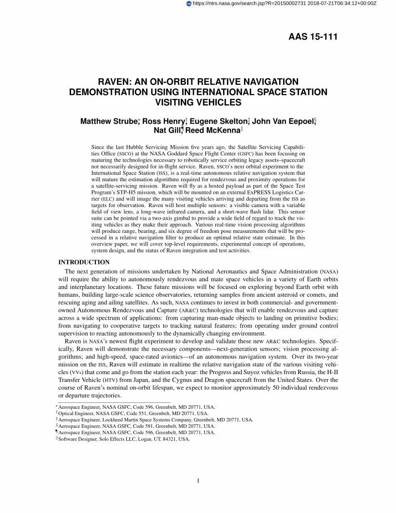
The Raven IRCam is a Long Wave Infrared (LWIR) camera sensitive in the 8-14 µm wavelength range andis a build-to-print version of the LWIR camera used in the TriDAR DTOs.7, 8 It contains a DRS TechnologiesU6010 Vanadium Oxide (VOx) 640 x 480 pixel micro-bolometer array. The IRCam includes an internal shutterfor on-oribit camera calibration and flat field correction. The camera operates via a Universal Serial Bus(USB) 2.0 interface that handles all power, video, command, and telemetry functions. The camera includes anathermalized, 50 mm f/1.0 lens that yields a 18◦ x 14◦ FOV.
The Raven Inertial Measurement Unit (IMU) is a commercially available STIM300 that has been screenedfor spaceflight by GSFC. It contains three Micro-Electric Mechanical System (MEMS) gyroscopes, threeMEMS accelerometers and three (unused for Raven) inclinometers. The IMU also contains internal temper-ature sensors (one for each gyro, one for each accelerometer, and one for each inclinometer) which are usedwith calibration data from thermal chamber testing to compensate for temperature effects while in operation.
The Raven flash lidar, shown unintegrated in Figure 6, collects data by first illuminating the relative scenewith a wide-beam 1572 nm laser pulse and then collecting the reflected light through a set of receive optics,which funnel the light on to a 256 x 256 focal plane array. By clocking the time between transmissionand reception, the focal plane array can accurately measure the distance to the reflected surface, as wellas the return intensity, at a rate of up to 30 Hz. Additionally, the lidar utilizes a Liquid Crystal VariableRetarder (LCVR) which acts as an optical switch to provide either a 20◦ or 12◦ transmit FOV: this ability totoggle between two FOVs allows operators to maximize the receive signal to noise ratio across large separationdistances. The lidar uses a variety of interfaces such as 28 Volt power input, RS-422 command and telemetrylinks, and a set of LVDS data link pairs. The flash LIDAR is functionally similar to a unit that flew as part ofthe Sensor Test for Orion Rel-Nav Risk Mitigation (STORRM) DTO on STS-134 in May, 2011.9
The second main subassembly in Raven is the Gimbal Baseplate Assembly, which is comprised of thebaseplate, gimbal tower assembly, active/passive launch locks, and secondary support electronics. The base-plate serves as Raven’s interface to STP-H5 and provides mounting accommodations for most of the Ravenflight hardware. The gimbal tower assembly located on the top of the baseplate is actually two pieces: theEnhanced Deployment and Positioning Mechanism (EDAPM)—a Commercial Off-The-Shelf (COTS) azimuth-over-elevation gimbal which points the Sensor Enclosure over a wide field of regard—and the gimbal tower—a mechanical interface adapter between the gimbal and the baseplate. Also on the top of the baseplate arelaunch lock tie downs—used to secure the gimbal and Sensor Enclosure during launch—and thermal accom-modations to protect the secondary hardware mounted to the bottom of the baseplate. Mounted underneaththe baseplate are the Enhanced Motor Power Drive (EMPD) and the Auxiliary Electronics Box (AEB). TheEMPD will control both the azimuth and elevation motors on the EDAPM as well as the zoom and focus motorson the VisCam MZL. The AEB is a catch-all electronics box that ties together the various electrical systems ofRaven: it contains voltage converters for the various pieces of hardware, current inrush limiters, and launchlock power and control services.
Raven uses a SpaceCube 2.010 Engineering Model as its primary command and data handling processor.The same processor design flew aboard Space Test Program-Houston 4 (STP-H4) as part of the ISS Space-Cube 2.0 experiment. Figure 7 shows the top and bottom sides of the board with the three Xilinx Virtex-5Field Programmable Gate Arrays (FPGAs) used in the Engineering Model architecture. One FPGA is themain board controller, providing interfaces to radiation hardened static random-access memory (SRAM),double data rate (DDR) Synchronous Dynamic Random Access Memory (SDRAM), a custom 16-channelanalog to digital convertor (ADC), two flash memory modules, and 10/100 Ethernet. The other two FPGAshost application-specific code and are where the Raven flight software and VHSIC hardware description lan-
8

guage (VHDL) will run. Each of these FPGAs has two DDR memory modules, one flash modules, and a varietyof external interfaces. The SpaceCube 2.0 architecture includes the ability to reprogram the two application-specific FPGAs;11 Raven developers plan to use this capability to implement a variety of new software andVHDL over the life of the experiment.
5
majority of the circuitry was constrained. Figure 3 shows the bottom side of the board in a test fixture.
Figure 2 - Processor Engineering Model, Top Side
Figure 3 - Processor Engineering Model, Bottom Side
B. Flight Card Overview
The SpaceCube v2.0 flight processor card design leverages design experience from all prior SpaceCube processor versions. The overall processing architecture strikes a perfect balance between computational potential, memory and interconnect resources, necessary support features for reliability, board size, and power. Many lessons learned from the EM were folded into the flight design. Most importantly, the flight design complies with the IPC-6012B Class 3/A standard, as will be discussed in detail.
The flight processor card is an extended version of 3U measuring 100 x 190 mm. When designing a board with a small constrained area, it is very important to focus time throughout the design phase on parts placement. Realistic parts placement studies are imperative prior to finishing the schematic. The board designer needs to be cognizant of leaving room for discrete parts, vias, mechanical stiffeners, and potential of board rework. The results of proper design planning is seen in the pictures of the flight processor card in Figure 4 and Figure 5.
Figure 4 - Flight Processor Card, Top Side
Figure 5 - Flight Processor Card, Bottom Side
The architecture selected consists of a radiation hardened Aeroflex FPGA, two Xilinx Virtex-5 FPGAs, various memory modules, multiple gigabit and LVDS/RS422 front-panel and backplane interconnects, 10/100 Ethernet, 16 analog channels, and secondary power circuitry that is cutting edge for space flight. A high-level diagram is shown in Figure 6. The Xilinx footprint handles either the 1752 CGA space grade device or the 1738 BGA commercial grade device. The commercial grade XC5VFX130T contains two embedded PowerPC440 processors.
Figure 6 - SpaceCube v2.0 Flight Processor Diagram
For interconnect, this design uses very small 85-pin Airborn Nano connectors in a back-to-back fashion. This increases the I/O count to three times that of the SpaceCube v1.0 within half the PWB real estate. These connectors support Ethernet, JTAG, RS422, LVDS, and 88 direct Xilinx signals that can be configured as serial or differential channels.
Figure 7. Raven flight science data processor: based on the SpaceCube 2.0 architecture.
BASELINE PROCESSING DESCRIPTIONThe Raven hybrid computing system features a mix of hardware-accelerated firmware cores and embedded
software libraries that are each designed to run optimally on SpaceCube’s multi-FPGA architecture. The basicbuilding blocks are VHDL cores that perform all of the interfacing to the flight hardware components—gimbal,sensors, auxiliary electronics, etc. Flight software is executed on multiple MicroBlazeTMsoft core processors,each with running a custom realtime Linux operating system. Device drivers bridge the gap between the hardrealtime operations of the VHDL cores and the soft realtime processing in software. A software message busprovides inter-processor communication, which allows software processes to synchronize operations acrossmultiple hardware processors.
Raven’s GN&C processing utilizes a mix of firmware and software components to maximize overall sys-tem throughput. The high-speed vision processing algorithms are implemented in firmware to leverage themassively parallel processing capable with FPGAs. More mathematically intense algorithms, such as the nav-igation filter, run as software processes on the soft core processors. Figure 8 shows the end-to-end data pathfor Raven’s GN&C architecture.
Each vision processing algorithm will generate either a bearing measurement or a full six-state pose mea-surement depending on the range to the vehicle. The lidar algorithm will additionally provide a directrange measurement during bearing mode operations. Raven’s GN&C-related sensors—the IMU and gimbalpotentiometers—are processed using the Sensor Processing (SP) application. Using raw potentiometer data,the SP application produces position and rate estimates for both the azimuth and elevation joints. Addition-ally, the SP application generates the field of view and focus estimates for the optical zoom lens and forwardsIMU data to the other GN&C applications.
Goddard Natural Feature Image Recognition (GNFIR)GNFIR is a natural feature image recognition application developed initially for the RNS experiment on
HST SM4.5, 6 It requires no fiducials on the target vehicle and utilizes an edge model of prominent featuresto track. The algorithm first reduces the imagery to edges through standard edge detection, then projectsthe model into the image plane using the previous pose measurement, searches for nearby edges and thenperforms a least squares minimization of the search results to arrive at a pose measurement.12 Figure 9 showsa simulated image of a Dragon rendezvous overlaid with the GNFIR algorithm’s tracking detail. Figure 10shows GNFIR working with infrared camera imagery. The figure also highlights recent updates to GNFIR totrack objects in images with cluttered backgrounds.
9

Figure 8. Raven’s Guidance, Navigation, and Control (GN&C) software architecture
FlashPose (FPose)FPose utilizes the flash lidar range and intensity point clouds to develop a pose measurement at close range
and a range and bearing measurement at farther distances. The algorithm leverages standard Iterative ClosestPoint (ICP) methods to match a model to the point cloud data13 and then converts the least squares minimiza-tion result to a pose measurement using the Horn algorithm.14 Figure 11 shows simulated lidar imagery of aDragon rendezvous and the Fpose algorithm tracking the vehicle.
Navigation FilterThe next step in the processing pipeline is to fuse the bearing and pose measurements from GNFIR-Vis,
GNFIR-IR, and FPose, along with measurements of the Raven joint angles and rates, into a state estimate ofthe vehicle. The Raven navigation filter architecture is built off the standard extended Kalman filter architec-ture.15 The filter performs the state and measurement updates at 1 Hz, while an output processing loop gener-ates input for gimbal at a higher 25 Hz while propagating in between measurement updates. Two different dy-namic formulations are implemented in the filter—a simple kinematic force model and a Clohessy-Wiltshiredynamic model—and ground operators can choose based on the current information available. Initially, oper-ators will use the simpler kinematic force model because it does not rely on external, imprecise information,such as its location relative to the ISS center-of-mass. The filter solution is exclusively used onboard to pro-vide the desired pointing vector for the Visual Tracking mode and is transmitted to the ground operators forevaluation. To increase processing speed, the Raven filter also implements a UDU formulation—where thecovariance matrix is factored into unit upper triangular and diagonal matrices—given the large number ofpose bias states included in the filter state vector.16 The filter also incorporates measurement editing usingunderweighting techniques and features consider states using the Schmidt-Kalman consider covariance.17
PROGRAM STATUSAs of January 2015, most of the Raven flight hardware has been integrated. The Sensor Enclosure and
Gimbal Baseplate Assembly have been mechanically integrated and successfully passed both azimuth andelevation range of motions tests. The Sensor Enclosure is completely electrically integrated with all safe-to-mates between the sensors and the processing and power electronics complete. The flight SpaceCubeelectronics box is undergoing environmental testing in parallel to Raven core vibration testing. Figure 12shows the remaining Raven testing activities and the ship date to STP-H5.
10

Figure 9. Goddard Natural Feature Image Recognition (GNFIR) tracking synthet-ically generated image of a Dragon vehicle. Dots represent tracked points used inthe solution; dot color corresponds to whether or not the point is successfully beingtracked. Inset image shows processed edge image.
Figure 10. Raw infrared image of the ISS (left) and Goddard Natural Feature ImageRecognition (GNFIR) edge tracking image (right).
NASA had to overcome many risks in order to be successful with Raven. By far the biggest hurdle has beenverifying that the Raven lidar does not interfere with any GN&C sensors aboard the approaching or departingVV. GSFC, Space Test Program (STP), and the ISS Program Office worked together to resolve this potentialissue by chartering the NASA Engineering and Safety Center (NESC) to conduct an independent assessment ofRaven and its effect on VVs. The assessment team found no credible fault could result in a catastrophic hazard;as of this writing, the ISS program office is still working the VV providers to concur with the assessment ofthe NESC by fully analyzing the possibility of any type of interference between Raven and their vehicles.
One of the other major risks faced by the project was the use of COTS and preexisting hardware onRaven in order to meet mission objectives within a reasonable budget and schedule while still meeting ISSsafety and mission assurance requirements. The 18-month development schedule forced the project to use a“capabilities-driven engineering approach” that resulted in using flight or flight-spare hardware from previ-ous missions—the VisCamera and flash lidar—and commercially available hardware—the IRCamera, gimbaland associated electronics—with no modifications. Additional analysis not included with the standard COTSproducts, or missing from legacy hardware, needed to be completed by the NASA team. In some cases, themission objectives were adjusted to accommodate less expensive and more readily available hardware.
11

Figure 11. FlashPose (FPose) registering an internal model—shown in blue—withsynthetically generated point cloud. The two small inset images show the variationsin the raw lidar range images at different points in the scenario.
RAVEN SUMMARY SCHEDULE
AUG SEPT OCT NOV DEC JAN FEB MAR RAVEN
GIMBAL
MECHANICAL PARTS
EPMD
SHIP
PROCUREMENTS & DELIVERIERABLES
AEB
PSR TRR
INTEGRATION
FABRICATION
EMI/EMC
VIBE
FLIGHT HARNESSING
MILESTONES
FABRICATION
RAVEN SYSTEM LEVEL INTEGRATION &
TESTING
STP-‐H5 INTEGRAITON AND TESTING FLOW (@ JSC)
LAUNCH LOCKS
SPACECUBE 2.0 IMU VISCAM
OPTICAL BENCH
RSE INTEGRATION
CPT
APR
CPT Thermal Vac.
STP-‐H5 I&T
SYSTEM TESTING
Figure 12. Raven summary schedule as of Janurary 2015
12

REFERENCES[1] “Asteroid Redirect Mission Broad Agency
Announcement,” https://www.fbo.gov.NNH14ZCQ002K.
[2] B. J. Naasz, M. Strube, J. V. Eepoel, B. W. Bar-bee, and K. M. Getzandanner, “Satellite Servic-ing’s Autonomous Rendezvous And DockingTestbed On The International Space Station,”Proceedings of the 34th AAS Guidance andControl Conference, No. AAS 11-072, Breck-enridge Colorado.
[3] J. Galante, J. V. Eepoel, M. Strube, N. Gill,M. Gonzalez, A. Hyslop, and B. Patrick, “PoseMeasurement Performance of the Argon Rel-ative Navigation Sensor Suite in SimulatedFlight Conditions,” Proceedings of the AIAAGuidance, Navigation, and Control Conference,Minneapolis, Minnesota.
[4] S. Voels, “Overview of the ExPRESS Pallet forPayload Developers,” Proceedings of the Con-ference and Exhibit on International Space Sta-tion Utilization–2001, Cape Canaveral, Florida,USA.
[5] B. J. Naasz, R. D. Burns, S. Z. Queen, J. V.Eepoel, J. Hannah, and C. E. Skelton, “TheHST SM4 Relative Navigation Sensor System:Overview and Preliminary Testing Results fromthe Flight Robotics Lab,” The Journal of the As-tronautical Sciences, Vol. 57, No. 1 and 2, Jan-June 2009, pp. 457–483.
[6] B. J. Naasz, J. V. Eepoel, S. Z. Queen, C. M. S.II, and J. Hannah, “Flight Results From the HSTSM4 Relative Navigation Sensor System,” Pro-ceedings of the 33rd AAS Guidance and Con-trol Conference, No. AAS 10-086, Brecken-ridge Colorado.
[7] S. Ruel and T. Luu, “STS-128 On-OrbitDemonstration of the TriDAR targetless ren-dezvous and docking sensor,” Proceedings ofthe 2010 IEEE Aerospace Conference, Big Sky,MO.
[8] S. Ruel, T. Luu, and A. Berube, “Space shuttletesting of the TriDAR 3D rendezvous and dock-ing sensor,” Journal of Field Robotics, Vol. 29,2012.
[9] J. A. Christian, H. Hinkel, C. N. D’Souza,S. Maguire, and M. Patangan, “The Sensor Testfor Orion RelNav Risk Mitigation (STORRM)Development Test Objective,” Proceedings ofthe 2011 AIAA Guidance, Navigation, and Con-trol Conference, No. AAS 11-6260.
[10] D. Petrick, A. Geist, D. Albaijes, M. Davis,P. Sparacino, G. Crum, R. Ripley, J. Boblitt, andT. Flatley, “SpaceCube v2.0 Space Flight Hy-brid Reconfigurable Data Processing System,”Proceedings of the 2014 IEEE Aerospace Con-ference, Big Sky, Montana, USA, March 2014.
[11] D. Petrick, D. Espinosa, R. Ripley, G. Crum,A. Geist, and T. Flatley, “Adapting the Re-configurable SpaceCube Processing System forMultiple Mission Applications,” Proceedings of
the 2014 IEEE Aerospace Conference, Big Sky,Montana, USA, March 2014.
[12] T. Drummond and R. Cipolla, “Real-Time Vi-sual Tracking of Complex Structures,” IEEETransactions on Pattern Analysis and MachineIntelligence, 2002.
[13] P. Besl and N. McKay, “A Method for Reg-istration of 3-D Shapes,” IEEE Trans on Pat-tern Analysis and Machine Intelligence, Vol. 14,1992.
[14] B. K. P. Horn, “Closed-form solution of abso-lute orientation using unit quaternions,” Journalof the Optical Society of America, Vol. 4, 1987.
[15] S. F. Schmidt, “The Kalman Filter: Its Recogni-tion and Development for Aerospace Applica-tions,” Journal of Guidance, Control, and Dy-namics, Vol. 4, 1981.
[16] C. L. Thornton and G. J. Bierman, “Gram-Schmidt algorithms for covariance propa-gation?,” International Journal of Control,Vol. 25, No. 2, 1977, pp. 243–260.
[17] S. F. Schmidt, “Application of state-space meth-ods to navigation problems,” Advances in Con-trol Systems, Vol. 3, 1966, pp. 293–340.
ACRONYMS AND ABBREVIATIONSADC analog to digital convertor
AEB Auxiliary Electronics Box
AR&C Autonomous Rendezvous and Capture
ARM Asteroid Redirect Mission
BAA Broad Agency Announcement
CAD Computer-Aided Design
COTS Commercial Off-The-Shelf
DDR double data rate
DoD Department of Defense
DPP Dextre Pointing Package
DTO Demonstration Test Objective
EDAPM Enhanced Deployment and PositioningMechanism
ELC ExPRESS Logistics Carrier
EMPD Enhanced Motor Power Drive
FOV Field of View
FPGA Field Programmable Gate Array
FPose FlashPose
FRAM Flight Releasable Attachment Mechanism
GN&C Guidance, Navigation, and Control
GNFIR Goddard Natural Feature Image Recognition
GSE ground support equipment
GSFC Goddard Space Flight Center
HST Hubble Space Telescope
HTV H-II Transfer Vehicle
ICP Iterative Closest Point
IMU Inertial Measurement Unit
13

ISEM ISS SpaceCube Experiment–Mini
ISS International Space Station
KSC Kennedy Space Center
LCVR Liquid Crystal Variable Retarder
LEO Low Earth Orbit
LVDS Low Voltage Differential Signaling
LVLH Local Vertical, Local Horizontal
LWIR Long Wave Infrared
MZL Motorized Zoom Lens
NASA National Aeronautics and Space Administration
NESC NASA Engineering and Safety Center
RNS Relative Navigation Sensor
SDRAM Synchronous Dynamic Random Access Memory
SM4 Servicing Mission 4
SPDM Special Purpose Dexterous Manipulator
SRAM static random-access memory
SSCO Satellite Servicing Capabilities Office
SSRMS Space Station Remote Manipulator System
STORRM Sensor Test for Orion Rel-Nav Risk Mitigation
STP Space Test Program
STP-H4 Space Test Program-Houston 4
STP-H5 Space Test Program-Houston 5
USB Universal Serial Bus
VHDL VHSIC hardware description language
VOx Vanadium Oxide
VV visiting vehicle
14