low carbon desalination by innovative membrane materials
TRANSCRIPT

University of Wollongong University of Wollongong
Research Online Research Online
Faculty of Engineering and Information Sciences - Papers: Part B
Faculty of Engineering and Information Sciences
2018
Low Carbon Desalination by Innovative Membrane Materials and Low Carbon Desalination by Innovative Membrane Materials and
Processes Processes
Hung Duong University of Technology Sydney, Le Quy Don Technical University, [email protected]
Ashley Ansari University of Wollongong, [email protected]
Long D. Nghiem University of Technology Sydney, [email protected]
Thao Pham Le Quy Don Technical University
Thang Pham Le Quy Don Technical University
Follow this and additional works at: https://ro.uow.edu.au/eispapers1
Part of the Engineering Commons, and the Science and Technology Studies Commons
Recommended Citation Recommended Citation Duong, Hung; Ansari, Ashley; Nghiem, Long D.; Pham, Thao; and Pham, Thang, "Low Carbon Desalination by Innovative Membrane Materials and Processes" (2018). Faculty of Engineering and Information Sciences - Papers: Part B. 2066. https://ro.uow.edu.au/eispapers1/2066
Research Online is the open access institutional repository for the University of Wollongong. For further information contact the UOW Library: [email protected]

Low Carbon Desalination by Innovative Membrane Materials and Processes Low Carbon Desalination by Innovative Membrane Materials and Processes
Abstract Abstract Seawater and brackish water desalination has been a practical approach to mitigating the global fresh water scarcity. Current large-scale desalination installations worldwide can complementarily augment the global fresh water supplies, and their capacities are steadily increasing year-on-year. Despite substantial technological advance, desalination processes are deemed energy-intensive and considerable sources of CO2emission, leading to the urgent need for innovative low carbon desalination platforms. This paper provides a comprehensive review on innovations in membrane processes and membrane materials for low carbon desalination. In this paper, working principles, intrinsic attributes, technical challenges, and recent advances in membrane materials of the membrane-based desalination processes, exclusively including commercialised reverse osmosis (RO) and emerging forward osmosis (FO), membrane distillation (MD), electrodialysis (ED), and capacitive deionisation (CDI), are thoroughly analysed to shed light on the prospect of low carbon desalination.
Disciplines Disciplines Engineering | Science and Technology Studies
Publication Details Publication Details Duong, H. Cong., Ansari, A. J., Nghiem, L. D., Pham, T. M. & Pham, T. D. (2018). Low Carbon Desalination by Innovative Membrane Materials and Processes. Current Pollution Reports, 4 251-264.
This journal article is available at Research Online: https://ro.uow.edu.au/eispapers1/2066

1
Low Carbon Desalination by Innovative Membrane Materials and 1
Processes 2
Summited to 3
Current Pollution Reports 4
Hung C. Duonga,b,*, Ashley J. Ansaric, Long D. Nghiema, Thao. M. Phamb, and Thang D. 5
Phamb 6
a Centre for Technology in Water and Wastewater, University of Technology Sydney, 7
Ultimo, NSW 2007, Australia 8
b Le Quy Don Technical University, Hanoi, Vietnam 9
c Strategic Water Infrastructure Laboratory, School of Civil, Mining and Environmental 10
Engineering, University of Wollongong, Wollongong, NSW 2522, Australia 11
12
13
14
15
16
17
18
19
_______________________ 20
* Corresponding author: 21
Hung Cong Duong, Email: [email protected]; Tel: +84 971 696 607 22

2
Abstract: Seawater and brackish water desalination has been a practical approach to mitigating 23
the global fresh water scarcity. Current large-scale desalination installations worldwide can 24
complementarily augment the global fresh water supplies, and their capacities are steadily 25
increasing year-on-year. Despite substantial technological advance, desalination processes are 26
deemed energy-intensive and considerable sources of CO2 emission, leading to the urgent need 27
for innovative low carbon desalination platforms. This paper provides a comprehensive review 28
on innovations in membrane processes and membrane materials for low carbon desalination. In 29
this paper, working principles, intrinsic attributes, technical challenges, and recent advances in 30
membrane materials of the membrane-based desalination processes, exclusively including 31
commercialised reverse osmosis (RO) and emerging forward osmosis (FO), membrane 32
distillation (MD), electrodialysis (ED), and capacitive deionisation (CDI), are thoroughly 33
analysed to shed light on the prospect of low carbon desalination. 34
Keywords: low carbon desalination; membrane-based desalination; reverse osmosis (RO); 35
forward osmosis (FO); membrane distillation (MD); electrodialysis (ED); capacitive 36
deionisation (CDI). 37

3
1. Introduction 38
Desalination has become a practical approach to augmenting fresh water supplies in many 39
water-stressed areas around the world [1]. According to the International Desalination 40
Association, desalination plants worldwide can provide more than 86.8 million cubic meters of 41
desalinated water per day to meet the daily fresh water demand of more than 300 million people 42
[2]. The global desalination capacity is increasing at a steadfast pace and is expected to double 43
by 2030 given huge financial investments [3]. The global desalination market had been long 44
time dominated by conventional thermal distillation processes such as multi-stage flash (MSF) 45
and multi-effect distillation (MED). However, in recent decades membrane-based separation 46
processes, particularly reverse osmosis (RO), have become the leading desalination technology 47
and are preferable to the conventional thermal distillation for new and projected desalination 48
installations [1, 4, 5]. Compared to conventional thermal distillation, the membrane-based 49
processes are by far more energy efficient. For example, the energy demand of the seawater RO 50
process has approached closely to the theoretical minimum energy demand (i.e. 0.77 kW h/m3) 51
and is approximately ten-folds lower than that of the conventional thermal distillation processes 52
[6]. 53
The substantial growth of desalination has inevitably led to mounting environmental 54
concerns regarding to greenhouse-gas emission. Despite being the most energy efficient, the 55
seawater RO desalination process exhibits a carbon footprint of 2.562 kg CO2 per one cubic 56
meter of fresh water product [7]. Given the current global desalination capacity of 86.8 million 57
cubic meters of fresh water product per day, the annual carbon footprint of all desalination 58
installations worldwide is 79 Mt CO2, with a potential growth of 10 to 15% per annum [4]. In 59
this context, low carbon desalination processes are urgently needed to sustain the growth of 60
desalination to meet increasing global fresh water demand while reducing desalination carbon 61
footprint to reach the global CO2 emission target set in the Paris Agreement on climate change 62
in 2015 [8]. 63
This paper aims at providing a comprehensive review of innovative desalination membrane 64
processes and membrane materials with respects to energy consumption and hence carbon 65
footprint reduction. The desalination membrane-based processes discussed in this review paper 66
include maturely commercialised RO and other emerging processes such as forward osmosis 67
(FO), membrane distillation (MD), electrodialysis (ED), and capacitive deionisation (CDI). 68

4
Working principles, intrinsic attributes, and technical challenges with respect to energy 69
efficiency and decarbonisation of each process are thoroughly analysed and discussed. 70
2. Reverse osmosis 71
In reverse osmosis (RO) desalination, desalinated water is extracted from a saline solution 72
using a semi-permeable membrane that selectively favours the permeation of water. Energy is 73
required to push water through the membrane against the effect of the osmotic pressure gradient 74
between the saline feed and the permeate streams. The theoretical minimum energy demand for 75
the RO process of seawater at water recovery of 50% is 1.06 kWh/m3 [1]. However, the actual 76
energy consumption of seawater RO desalination exceeds this minimum value because a 77
hydrostatic pressure much higher than the osmotic pressure of seawater is required to obtain a 78
desired process water flux. Pre-treatment of the feed water and post-treatment of the permeate 79
further increase the energy consumption of RO processes compared to the theoretical minimum 80
value. 81
Recent technological advancements in membrane materials and energy recovery devices 82
have led to a significant reduction in energy consumption of the RO process. Currently, a state-83
of-the-art seawater RO process can achieve an energy consumption from 3.0 to 3.5 kWh/m3 [4]. 84
Of this total energy consumption, the RO step consumes 2.2 kWh/m3, and 0.3 kWh/m3 is for 85
the pre-treatment step using ultra-filtration (UF) [9]. Therefore, strategies for energy 86
consumption reduction, and hence for increased decarbonisation, of RO desalination mainly 87
focus on reducing the energy consumption of the RO and the pre-treatment steps. 88
The energy consumption of the RO step can be reduced by increasing membrane water 89
permeability. According to Cohen-Tanugi et al. [10], energy consumption of seawater RO can 90
decrease by 20% when the membrane water permeability increases three folds. Thus, ultra-91
permeable membranes using Aquaporin, carbon nanotubes, and graphene materials have been 92
explored and demonstrated for RO desalination [11-13]. In the RO process using these ultra-93
permeable membranes, water transports through the membrane under a different mechanism 94
compared to traditional membranes. Water channels in the ultra-permeable membranes 95
facilitate the transport of water molecules while not compromising the rejection of dissolved 96
salts, giving the ultra-permeable membranes a much higher water permeability but a similar salt 97
removal compared to traditional RO membranes [11-13]. Increased membrane water 98

5
permeability allows for the RO desalination operation at a lower applied pressure while 99
obtaining the same process water flux, thus decreasing the process specific energy consumption 100
[1]. 101
Process optimisation has also been approached to reduce the energy consumption and hence 102
to decarbonise fresh water production of RO desalination. One strategy to reduce RO energy 103
consumption is multi-staging the RO process. As demonstrated in Fig. 1, in a single-stage RO 104
process, a minimum hydrostatic pressure (PH) equal to the osmotic pressure of the concentrate 105
at the outlet of the RO module (C) is applied. Along the membrane module from the inlet, PH 106
is higher than the local osmotic pressure () of the concentrate. The difference between PH and 107
local causes the irreversible energy loss. In a multi-stage RO process, more high-pressure 108
pumps are used between RO membrane stages, and the applied pressure of each stage increases 109
with the order of the stage. This allows the applied pressure of each stage to approach closer to 110
the local . Thus, operating the RO process in multi-stage helps reduce the irreversible energy 111
loss and allows the RO process to approach the theoretical minimum energy consumption [1, 112
14, 15]. In other words, the seawater RO desalination process with infinite stages at water 113
recovery of 50% can achieve the theoretical minimum energy consumption of 1.06 kWh/m3. 114
Nevertheless, multi-staging the RO process also leads to increase in investment and operational 115
costs as more high-pressure pumps and maintenance are required. 116
117 Fig. 1. Schematic diagrams and energy saving of a single-stage and a multi-stage RO process 118
(adapted from [1]). 119

6
The energy consumption of RO desalination can be reduced by operating the process in 120
closed circuit or semi-batch mode [16, 17]. In closed circuit or semi-batch RO process, saline 121
feed water is continuously pumped into a variable-volume high pressure vessel connected with 122
spiral-wound RO membranes (Fig. 2). Fresh water is collected at the outlets of the membrane 123
modules while the pressurised concentrate is circulated back to the pressure vessel to mix with 124
the feed water. The residual pressure of the concentrate is reused to pressurise the feed water, 125
hence reducing the applied pressure on the feed water. The pressure of the mixed feed water in 126
the pressure vessel is increased overtime with the increase in the osmotic pressure of the mixed 127
feed. When a desired water recovery has been achieved, the concentrated mixed feed water (i.e. 128
brine) is discharged and replaced by fresh water feed before starting the next operation cycle. 129
Simulation results have demonstrated that semi-batch and closed circuit operation can reduce 130
energy consumption of a brackish water RO desalination process by 64% [16]. 131
132 Fig. 2. Schematic diagram of a close circuited RO process. 133
Membrane fouling is an intrinsic technical issue for RO desalination. Fouling leads to 134
decline in the process water flux or increase in the applied pressure, inevitably increasing the 135
specific energy consumption of the RO process. Various methods have been explored to 136
mitigate and control membrane fouling during the RO desalination process, of which pre-137
treatment of the feed water is a prerequisite. Conventionally, media filters, low pressure UF, 138
and probably dissolved air flotation (DAF) are incorporated before RO membrane modules to 139
pre-treat the feed water. This pre-treatment train has proven capable of effectively removing 140
turbidity and assimilable organic carbon (AOC), thus providing quality feed water to the RO 141
membrane modules. However, this pre-treatment step (particularly UF) still contributes 0.3 142
kWh/m3 to the total energy consumption of the RO process. Practising subsurface intakes (e.g. 143
using beach wells and galleries for pre-treatment) can help reduce the energy consumption for 144
pre-treatment and hence for the overall process of seawater RO desalination [18]. Geological 145

7
properties of beach wells and galleries retain and provide biological removal of organic matter, 146
suspended sediments, and dissolved organic compounds, thus offering a cost-effective and 147
energy saving pre-treatment prior to the RO membranes [18]. Nevertheless, this pre-treatment 148
method is limited to feed waters with low a membrane fouling propensity. 149
A novel approach to reducing energy consumption of pre-treatment in RO desalination is to 150
deploy gravity driven membranes (GDM) [19-21]. In a GDM pre-treatment system, feed water 151
is dead-end filtered through UF membrane under a hydrostatic pressure regenerated by a water 152
head, obviating the need for a high-pressure pump as required in normal UF operation. A 153
beneficial biofilm consisting eukaryotic organisms formed on the UF membrane surface 154
biodegrades and hence effectively removes rejected organic particles and colloids from the feed 155
water, leading to a lower fouling potential in the subsequent RO process. The beneficial biofilm 156
also helps stabilise the water flux of the UF membrane without the need for backwash or 157
chemical cleaning. As a result, the pre-treatment energy consumption of seawater feed using 158
GDM could be markedly reduced to 0.01 kWh/m3 compared to 0.3 kWh/m3 for a normal UF 159
pre-treatment [4]. Though, GDM pre-treatment was not able to reduce dissolved organic carbon 160
content in the pre-filtered water, hence a submerged GDM system combined with carrier 161
biofilm processes was proposed for a more effective pre-treatment before the RO desalination 162
process [21]. 163
In addition to reducing energy consumption, low carbon RO desalination can be achieved 164
by coupling RO with renewable energy sources such as solar, wind, and geothermal energies 165
[4, 5, 22-24]. Powered by renewable energy, RO desalination plants can approach to zero-166
carbon emission as they can minimise the consumption of electrical energy sourced from fossil 167
fuel. Indeed, wind farms have been built beside RO desalination plants in Australia to achieve 168
carbon offset of fresh water production from seawater. However, the intermittent nature of 169
renewable energy sources requires effective energy storage methods to prevent the frequent 170
shutdowns of the RO desalination plants. Amongst the proposed energy storage methods, grid-171
scale storage based on the concept of pumped hydro and osmotic battery are particularly of 172
interest. More details about these energy storage strategies can be found elsewhere [4, 25]. 173

8
3. Forward osmosis 174
Forward osmosis (FO) is an osmotically driven membrane process that has a number of 175
inherent advantages for providing low carbon desalination. The significant energy benefits of 176
FO rely on the natural osmotic pressure gradient created between the feed (source water) and 177
draw solution (osmotic agent). This salinity gradient provides the driving force for water 178
transport across the semi-permeable membrane, theoretically without any external energy input. 179
The FO process also exhibits a low fouling propensity, high contaminant rejection, and can 180
operate at high osmotic pressure driving forces, beyond the limits of RO [26]. Thus, FO is 181
strongly suited for complex source waters that have a high fouling potential or high salinity 182
which would otherwise not be compatible with RO treatment. Despite these advantages, an 183
additional desalination process is required to separate fresh water from the diluted draw solute 184
following the FO process. This fresh water extraction step can be achieved using thermal or 185
membrane separation processes and is responsible for the majority of energy consumed in a 186
hybrid FO process. 187
The most energetically favourable configuration is when FO is used as a standalone 188
desalination process in which fresh water extracted by the FO membrane is used to dilute a 189
draw solution for beneficial uses. The only energy requirement is the electricity to drive the 190
water circulation pumps to minimise external concentration polarisation and membrane fouling 191
[27]. Despite the potential for low carbon desalination, standalone FO applications have only 192
been realised in niche areas, including fertiliser drawn [28] and sugar drawn brackish water 193
desalination for emergency drinking relief [29]. In these applications, spontaneous water 194
permeation from the saline water feed through the membrane dilutes the draw solution to 195
provide a beneficial product, negating the need for high retention draw solute separation [30]. 196
Researchers have demonstrated the potential of fertiliser drawn FO, however integration with 197
nano-filtration (NF) is required to further dilute the draw solution and meet fertigation standards 198
[28]. Nevertheless, the fertiliser drawn FO-NF process was found to consume 21% less energy 199
than a UF-RO system [31]. Alternative osmotic dilution applications involve algae dewatering 200
using seawater or RO brines, however fresh water is lost during the process [32]. The task of 201
finding suitable draw solutions with high osmotic pressures for beneficial applications remains 202
a major challenge for the practical adoption of standalone FO desalination. 203

9
Apart from those standalone applications discussed above, FO must be coupled with an 204
additional separation process to achieve complete water treatment and desalination. In other 205
words, FO is considered as a pre-treatment step for other desalination processes such as RO, 206
which can separate the draw solute and produce fresh water. Combined hybrid FO processes 207
have gained attention because of the low fouling potential and superior pre-treatment that FO 208
provides at relatively low energy. Nevertheless, because of the extensive energy requirement to 209
separate the high osmotic pressure draw solutions, strategic selection of the source water, draw 210
solute, and regeneration process is needed to achieve energy-savings. For example, an FO-RO 211
hybrid system for seawater desalination (Fig. 3a) can never consume less energy than direct RO 212
at the same recovery. Detailed equations for energy calculation of the FO-RO hybrid and the 213
single RO desalination process can be found elsewhere [26]. Since the draw solution osmotic 214
pressure must be greater than seawater, the minimum energy required for RO desalination is 215
always higher for a hybrid FO-RO system. Strategically integrating wastewater treatment and 216
seawater desalination (Fig. 3b) has been proposed to reduce the specific energy consumption of 217
RO [33, 34]. Using wastewater as the feed solution to dilute the seawater draw solution has 218
resulted in lower costs compared to conventional seawater desalination with RO, mostly due to 219
the reduced RO operating pressure [35]. To illustrate, the estimated specific energy 220
consumption for a low pressure FO-RO system ranges between 1.3 and 1.5 kWh/m3, which is 221
significantly less than the conventional RO process (i.e. 2.2 kWh/m3) [36]. Despite this potential, 222
FO membrane fouling, low water flux and issues regarding system scale-up remain significant 223
challenges for full-scale implementation of FO hybrid systems. 224
225 Fig. 3. FO-RO hybrid systems for (a) seawater desalination, and (b) simultaneous wastewater 226
treatment and seawater desalination [33]. 227

10
Another notable approach to improve the energy consumption of hybrid FO systems is to 228
adopt draw solute regeneration processes that utilise thermal energy instead of electrical energy 229
[37]. For example, thermally responsive draw solutes such as ammonia carbon dioxide 230
(NH3/CO2) are easily regenerated using low grade heat, by converting the ammonium salts into 231
ammonia and carbon dioxide gas [38]. Pilot-scale demonstrations for shale gas produced water 232
using a NH3/CO2 FO process had a specific thermal energy consumption of approximately 275 233
kWhth/m3, which is significantly lower than the 633 kWhth/m
3 required for conventional 234
evaporative desalination methods [39]. Similarly, combining FO with MD is another option to 235
achieve energy savings by utilising low grade heat or solar thermal energy sources. As discussed 236
in the section 4, MD has exceptional salt rejection and is not limited by osmotic pressure, as 237
compared with pressure driven processes. Because MD might be prone to fouling, FO can 238
provide pre-treatment to reduce organic fouling and inorganic scaling in MD, as shown by 239
successful demonstrations in treating challenging solutions such as municipal and dairy 240
wastewater [40, 41], activated sludge [42] and landfill leachate [43]. It is noteworthy that the 241
benefits of FO in regard to treating high fouling potential and highly saline solutions cannot be 242
accurately captured by energy analysis since these complex solutions are often incompatible 243
with conventional desalination processes [26]. 244
A related process with potential to complement low carbon desalination is pressure retarded 245
osmosis (PRO). This emerging technology is based on the same principal as FO, however the 246
salinity gradient energy is harvested via enclosing the draw solution and capturing the 247
mechanical energy created by the increasing draw solution volume [44]. Hydro turbines or 248
energy recovery devices are used to convert this mechanical energy to electricity to power a RO 249
desalination process. PRO feasibility strongly depends on the magnitude of available salinity 250
gradients since a number of energy inputs (i.e. pumping and pre-treatment) are required to 251
effectively operate the process. Interest in incorporating PRO with RO desalination plants (Fig. 252
4) has shown theoretical reductions in energy consumption when impaired water sources are 253
available, however a number of practical considerations are yet to be addressed as discussed 254
elsewhere [45]. 255

11
256 Fig. 4. Schematic diagram of an integrated PRO-RO process for low carbon desalination. 257
4. Membrane distillation 258
Membrane distillation (MD), a thermally driven membrane separation process, embodies 259
several attributes ideal for low carbon desalination. The MD desalination process utilises a 260
hydrophobic microporous membrane to separate a hot saline feed and a cold fresh distillate and 261
the temperature difference between two sides of the membrane as the process driving force. 262
Thermal energy is the primary energy input into the MD desalination process [46, 47], and the 263
MD process can be efficiently operated at mild feed temperature (i.e. 40−80 C), allowing for 264
the deployment of waste heat or solar thermal to power the process. Thus, where these low-265
grade energy sources are available, MD can be an attractive energy-saving and low carbon 266
desalination technology platform. Moreover, as a thermally driven separation method, the MD 267
process is negligibly subject the osmotic pressure of the feed solution and hence compatible 268
with highly saline solutions, extending its applications for desalination of brines from RO and 269
other desalination processes. In addition, since the MD process does not involve a high 270
hydrostatic pressure, it is significantly less prone to membrane fouling, thus obviating the need 271
for intensive feed water pre-treatment like in RO. 272
MD configurations strongly affect the energy consumption of the process. In practice, MD 273
can be operated in four basic configurations, including direct contact membrane distillation 274
(DCMD), air gap membrane distillation (AGMD), vacuum membrane distillation (VMD), and 275
sweeping gas membrane distillation (SGMD). Amongst these configurations, DCMD exhibits 276
12
the lowest process thermal efficiency because the hot feed and the cold distillate streams are 277
separated by only a thin membrane in DCMD, leading to a noticeable conduction heat loss 278
through the membrane. The deployment of vacuum and sweeping gas on the permeate side of 279
the membrane in VMD and SGMD helps alleviate the conduction heat loss, and hence 280
improving their thermal efficiency compared to DCMD. Similarly, in AGMD, an air gap is 281
inserted between the feed and distillate streams to mitigate the conduction heat loss, and in 282
tandem facilitate the recovery of the condensation latent heat. Thus, AGMD can achieve a much 283
higher thermal efficiency than DCMD. 284
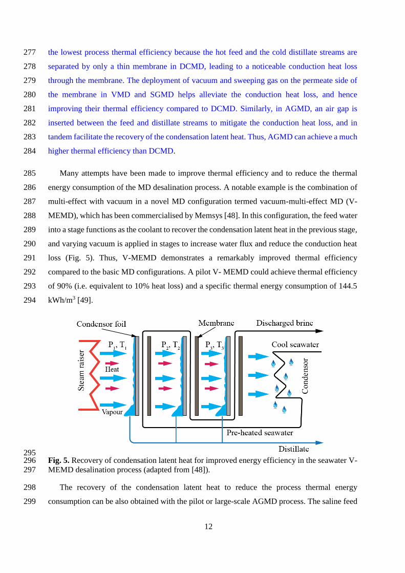
Many attempts have been made to improve thermal efficiency and to reduce the thermal 285
energy consumption of the MD desalination process. A notable example is the combination of 286
multi-effect with vacuum in a novel MD configuration termed vacuum-multi-effect MD (V-287
MEMD), which has been commercialised by Memsys [48]. In this configuration, the feed water 288
into a stage functions as the coolant to recover the condensation latent heat in the previous stage, 289
and varying vacuum is applied in stages to increase water flux and reduce the conduction heat 290
loss (Fig. 5). Thus, V-MEMD demonstrates a remarkably improved thermal efficiency 291
compared to the basic MD configurations. A pilot V- MEMD could achieve thermal efficiency 292
of 90% (i.e. equivalent to 10% heat loss) and a specific thermal energy consumption of 144.5 293
kWh/m3 [49]. 294
295 Fig. 5. Recovery of condensation latent heat for improved energy efficiency in the seawater V-296
MEMD desalination process (adapted from [48]). 297
The recovery of the condensation latent heat to reduce the process thermal energy 298
consumption can be also obtained with the pilot or large-scale AGMD process. The saline feed 299

13
water can be circulated through the coolant channel to act as a coolant (Fig. 6). Given the long 300
coolant channel, the feed water is sufficiently preheated by the condensation latent heat. The 301
preheated feed water then can be additionally heated by an external heat source to reach a 302
desired temperature prior to entering the feed channel of the AGMD membrane module (Fig. 303
6). Duong et al. [47] optimised a pilot seawater AGMD process with internal latent heat 304
recovery. The authors highlighted the importance of process optimisation to enhance energy 305
efficiency and hence to reduce the specific energy consumption of the process. The feed inlet 306
temperature and water circulation rate were critical operating parameters profoundly affecting 307
the process distillate production and thermal efficiency. Operating the AGMD process at high 308
feed inlet temperature and low water circulation rate was beneficial regarding to the process 309
energy efficiency. At the optimum operating conditions, the AGMD process achieved specific 310
thermal and electrical energy consumption of 90 and 0.13 kWh/m3, respectively [47]. 311
312 Fig. 6. A seawater AGMD desalination process with internal condensation latent heat recovery. 313
Unlike in AGMD, the recovery of latent heat in DCMD can only be viable when using an 314
external heat exchanger to recover latent heat accumulated in the distillate stream to preheat the 315
feed stream [50]. In the DCMD process combined with an external heat exchanger, the process 316
energy consumption is strongly influenced by the relative flow rate between the feed and the 317
distillate streams and the surface areas of the heat exchanger and the membrane module. Lin et 318
al. [50] reported that the DCMD process could obtain a minimum specific thermal energy 319
consumption of 8 kWh/m3 with infinite heat exchanger and membrane module surfaces at a 320
critical relative flow rate. However, it is worth noting that it is unpractical to use the DCMD 321
process with infinite heat exchanger and membrane module surfaces. 322

14
Another approach to reducing energy consumption of the DCMD process is to recover the 323
sensible heat of the brine stream by brine recycling. In the DCMD process, particularly for the 324
small-scale system with short membrane channels, the warm brine leaving the membrane 325
module contains a considerable amount of sensible heat. Brine recycling enables the recovery 326
of the brine sensible heat, thus leading to reduction in the process thermal energy consumption. 327
Indeed, Duong et al. [51] demonstrated that recycling brine in a small-scale DCMD process 328
helped reduce the process specific thermal energy consumption by more than half. Recycling 329
brine also facilitated the utilisation of the membrane surface area to increase the process water 330
recovery. Along with other operating parameters, the water recovery of the seawater DCMD 331
desalination process with brine recycling determined the process energy consumption, and the 332
optimal water recovery with respect to energy consumption was in the range from 20 to 60% 333
[51]. 334
Coupling MD with waste heat and renewable energy is a practical approach to low carbon 335
desalination. The MD process powered by industrial waste heat and solar thermal energy has 336
been successfully demonstrated for fresh water provision [49, 52-57]. A notable example can 337
be the DCMD process supplied with waste heat from a gas fired power station to reclaim fresh 338
water from saline demineralisation regeneration waste [53]. The process was trialled for over 339
three months, and a high-quality distillate with total dissolved salts rejection of 99.9% was 340
obtained [53]. A fully solar powered MD system was also deployed for potable water provision 341
in arid remote areas [56]. The system mainly consisted of a V-MEMD membrane module, a 342
solar-thermal collector, and a solar-PV panel. The engineered design of the system rendered it 343
a portable, reliable, environmentally friendly, and sustainable desalination technology [56]. 344
High resistance to membrane fouling is a noticeable advantage of MD for low carbon 345
desalination applications. Most of the demonstrated MD processes for desalination applications 346
involved a negligible feed water pre-treatment. Feed water to the MD process was either raw or 347
pre-filtered (i.e. using paper filters or cartridge filters) seawater. When the MD process was 348
operated at low water recoveries, membrane fouling was mostly not evident even for extended 349
operation (i.e. for several months) [53, 54]. Membrane scaling caused by the precipitation of 350
inorganic sparingly soluble salts only occurred when the MD process was pushed beyond their 351
saturation limits. The scale layers formed on the membrane surface limited the active membrane 352
surface for water evaporation, aggravated the temperature and concentration polarisation effects, 353
and altered the membrane surface hydrophobicity, thus reducing the process water flux and 354

15
deteriorating the quality of the obtained distillate. However, the scale formation in the MD 355
process could be effectively controlled by regulating the process operating parameters [58] or 356
rinsed out using non-toxic domestic cleaning agents [59]. The high resistance to membrane 357
fouling and scaling actually enables the MD process for treatment of brines from other 358
desalination processes such as RO, ED, FO, and CDI. 359
5. Electrodialysis 360
Electrodialysis (ED) is an electrically driven membrane separation process in which cation 361
exchange membranes (CEMs) and anion exchange membranes (AEMs) are used to facilitate 362
the selective transport of cations and anions through the membranes. In ED units, CEMs and 363
AEMs are placed alternatively between the anode and the cathode (Fig. 7). When an electric 364
field is applied, cations migrate through CEMs toward the anode, while anions move through 365
AEMs toward the cathode, leading to the depletion of salt concentration in the desalinated water 366
and the salt enrichment in the brine. 367
368 Fig. 7. Working principles of an ED process for desalination application. 369

16
In the ED process, electricity is consumed to generate the electric field between the 370
electrodes and to drive pumps for water circulation. The electricity consumed by the electrodes 371
(Pel) is the primary energy consumption of the ED process, and can be calculated as [60]: 372
elP n VI= (1) 373
where n is the number of ED cell pairs, V is the voltage drop over the cell pair, and I is the 374
electric current. Thus, the specific energy consumption (SEC) of the ED desalination process 375
can be expressed as [60]: 376
D
n VISEC
Q
=
(2) 377
where QD is the dilute flow rate (m3). The voltage drop over the cell pair is expressed as: 378
non Ohm OhmV r I −= + (3) 379
where non-Ohm is the non-Ohmic voltage drop and rOhm is the overall Ohmic resistance of the 380
cell pair. The non-Ohmic voltage drop depends on salt concentrations and the hydrodynamics 381
of the concentrate and the dilute compartments, and it becomes significant when the salt 382
concentration gradient between the concentrate and the dilute compartments increases. The 383
overall Ohmic resistance is composed of membrane resistances and the resistances of the dilute 384
and concentrate compartments. It has been proved that overall Ohmic resistance is inversely 385
proportional to the salt concentrations in the dilute and concentrate departments [60]. 386
For the ED desalination process, the dilute flow rate is dependent on the transport rate of 387
ions through the ion exchange membranes. A higher dilute flow rate can be achieved with an 388
elevated ions transport rate. The flux of an ion (Ji) through the ED membranes can be expressed 389
as [60]: 390
ii i i
i
t iJ D C
z F= − +
(4) 391

17
where D is the electrolyte diffusion coefficient of the ion, Ci is the ion concentration gradient, 392
ti is the migration transport number, i is the current density, zi is the valence of the ion, and F is 393
Faraday’s constant. 394
Eqs. (1-4) demonstrate a profound influence of the feed water salinity on the specific energy 395
consumption of the ED process. Increasing feed salinity results in not only a higher salt 396
concentration gradient between the dilute and the concentrate compartments (Ci) but also a 397
decreased current density (i) due to the concentration polarisation effect, hindering the transport 398
of ions through the membranes. Increasing feed salinity also magnifies the non-Ohmic voltage 399
drop over the cell pair (non-Ohm), hence raising the energy consumption of the ED process. For 400
low salinity desalination applications, the ED process is more energy efficient than RO. Indeed, 401
an ED process with feed water salinity 2500 ppm exhibits a specific energy consumption from 402
0.7 to 2.5 kWh/m3 [6, 23]. However, the energy consumption of the ED process considerably 403
exceeds that of RO when treating feed waters with salinity above 5000 ppm. As a result, ED is 404
largely applied for desalination of brackish water with limited salinity [6, 60]. 405
Membrane fouling is another issue that affects the energy consumption of the ED process 406
for desalination applications [60-62]. There is a consensus that ED is less subject to membrane 407
fouling than RO; however, membrane fouling is still considered one of the limiting factors of 408
the ED desalination process [60]. In the ED process, under the electric field, negatively charged 409
colloidal particles ubiquitous in seawater or brackish are pushed toward the anode. The ion 410
exchange membranes act as barriers and stop the colloidal particles migration, leading to the 411
deposition of colloids on the membrane surface. The deposited colloids layers reduce membrane 412
ion selectivity but increase membrane resistance and the pressure drop along the compartments, 413
thus significantly increasing the energy consumption of the ED process. Sparingly soluble salts 414
(e.g. CaCO3 and CaSO4) in seawater or brackish water also pose a risk of membrane scaling, 415
particularly for the ED process operated at a high recovery rate. Common methods to prevent 416
membrane fouling and scaling include feed water pre-treatment using MF and UF, pH 417
adjustment, reduction of recovery rate, and membrane cleaning [60]. It is worth noting that 418
applying these methods inevitably results in an increased in the energy consumption of the ED 419
process. 420
Attempts to mitigate membrane fouling propensity and hence the energy consumption of 421
the ED process focus on membrane surface modification and process optimisation. Notable 422

18
examples for the membrane surface modification approach include the studies of Mulyati et al. 423
[61] and Vaselbehagh et al. [62]. In these studies, the AEMs surface was modified by adding 424
high molecular mass surfactants (e.g. poly sodium 4-styrene sulfonate and polydopamine) to 425
enhance the negative surface charge density, hydrophilicity, and roughness of the AEMs. The 426
surface-modified AEMs exhibited a higher antifouling potential and an increased membrane 427
stability compared to the pristine ones. 428
The development of the electrodialysis reversal (EDR) concept made a breakthrough in 429
membrane fouling mitigation and energy consumption reduction of the ED desalination process 430
[60, 63]. During an EDR desalination operation, the polarity of the electrodes and the diluate 431
and concentrate channels are regularly reversed to facilitate the periodic removal of colloids 432
and organic matter from the membrane surfaces. The foulants detached from the membrane 433
surfaces are subsequently rinsed out of the ED cells by the flowing solutions. Given this self-434
cleaning mechanism, the EDR process exhibits a significantly reduced membrane fouling 435
tendency compared to the ED process. The EDR concept also helps minimise feed water pre-436
treatment and membrane cleaning procedures, obviating the need for additional equipment such 437
as acids tanks, complexing agent tanks, dosing pumps and pH controllers [60]. Thus, the EDR 438
concept leads to a significant reduction in the energy consumption of the ED desalination 439
process. 440
6. Capacitive deionisation 441
The capacitive deionisation (CDI) process purifies water using the electrostatic adsorption 442
and desorption capacity of conductive porous electrodes. The CDI desalination process involves 443
two alternate steps: purification of salt water and regeneration of the electrodes (Fig. 8) [64-66]. 444
During the purification step, as salt water travels along the CDI cell, ions or charged molecules 445
migrate toward and subsequently are adsorbed by the oppositely charged electrodes, leading to 446
the depletion of salt concentrations in the salt water feed and the attainment of desalinated water. 447
During the electrodes regeneration step, the polarity of the electrodes is reversed, and the 448
charged ions and molecules that have been attached to the electrodes in the purification step are 449
desorbed from the electrodes and migrate back to the salt water. Thus, the adsorption capacity 450
of the electrodes is regenerated, and a brine stream is produced at the outlet of the CDI cell. 451

19
452 Fig. 8. Purification and regeneration steps in the CDI process (adapted from [64]). 453
CDI has emerged as a promising process for low carbon desalination applications. The CDI 454
desalination process is operated at a limited electrical voltage (i.e. 2V) and a low hydrostatic 455
pressure [64, 65, 67]. It does not require high pressure pumps and costly tubing materials (i.e. 456
stainless steel) like in the RO desalination process. The mild operation conditions also render 457
the CDI desalination process significantly less prone to fouling, thus obviating the need for 458
intensive feed water pre-treatment and regular membrane cleaning as required by the RO 459
process [64, 68]. The low-voltage operation also facilitates the coupling of CDI desalination 460
with renewable energy sources (e.g. solar and wind energy) [67, 69]. More importantly, a large 461
portion of the energy used for charging the electrodes during the purification step can be 462
recovered in the electrode regeneration step [70, 71], thus significantly reducing the total energy 463
demand and hence the carbon footprint of the CDI desalination process. 464
Like in ED, the desalination efficiency and energy consumption of the CDI process strongly 465
depend on the process operating conditions, particularly the feed water salinity [64]. Increasing 466
feed salinity results in an increase in the adsorption rate of ions to the electrodes but a reduction 467
in the ions removal efficiency of the CDI cell. To achieve a desired effluent salinity, a longer 468
adsorption interval or a higher electric current is required for more concentrated feed water, 469
thus increasing the specific energy consumption of the CDI process. Indeed, Porada et al. [72] 470
compared the specific energy consumption of the CDI and RO process and confirmed that CDI 471
was only competitive to RO with respect to energy consumption for feed water with salinity 472
approximately below 2000 ppm, which is the salinity of brackish water. Thus, similarly to ED, 473
the CDI process is considered best suited for the desalination applications of brackish water [64, 474
67, 72]. 475

20
The electrodes exert profound influences on the desalination efficiency and the energy 476
consumption of the CDI process. The CDI desalination mechanism is governed by electrostatic 477
adsorption of ions to the electrodes when they are in direct contact with salt water, and 478
electrostatic adsorption is the driving force for the transfer of ions. As a result, electrostatic 479
adsorption is the limiting factor of the CDI desalination process [64, 73, 74]. Key properties of 480
the CDI electrodes include specific surface area, median pore diameter, total pore volume, 481
resistance, and particularly specific capacitance. The specific capacitance, measured in F/g, is 482
the amount of electrical charges (in coulomb) that can be stored by one mass unit of the 483
electrode material under an electric potential of 1 volt. Thus, it is an indicator of the electrostatic 484
adsorption capacity of the electrode. 485
Considerable efforts have been devoted to exploring suitable electrodes for improved ions 486
separation and energy efficiency of the CDI process. The most commonly used CDI electrodes 487
are prepared from activated carbons with poly vinylidene fluoride used as a binder. Given the 488
high porosity and rich carbon content of activated carbons, the activate carbon electrodes 489
possess excellent specific surface areas (i.e. above 2000 m2/g), micro-pore structure with pore 490
sizes ranging from 1.0 to 2.5 nm and a total pore volume of 0.57 to 1.63 cm3/g, and specific 491
capacitance of 60 to 125 F/g [75]. The hydrophobic nature of activated carbons is a drawback 492
of activated carbon electrodes. It repels water solution from the activated carbon electrodes and 493
hinders the direct contact between the electrodes and the solution, thus negatively affecting the 494
adsorption capacity of the electrodes [64]. Novel materials such as carbide derived carbons, 495
carbon aerogel, carbon nanotubes (CNTs) and carbon nanofibers (CNFs), graphene, and 496
mesoporous carbons have also been proposed and demonstrated for the CDI desalination 497
process. Porada et al. [72, 76] reported an adsorption capacity increase by 28 − 44% for the 498
electrodes prepared from carbide derived carbons compared to those prepared by activated 499
carbons. The increased adsorption capacity of the carbide derived carbons electrodes was 500
attributed to the super specific surface area and the pore size tunability in the sub-nanometer 501
range of the carbide derived carbons material [76]. Similarly, electrodes prepared from carbon 502
aerogel exhibited high specific surface area, controllable pore size distribution, and superior 503
electrical properties; therefore, they were selected for many CDI desalination processes [77]. 504
Nano carbon materials such as CNTs, CNFs, and graphene have recently emerged as promising 505
materials for CDI electrodes. Given their nano-structures, electrodes prepared from CNTs, 506
CNFs, and graphene have specific surface areas considerably higher than those offered by the 507

21
activated carbons electrodes. CNTs, CNFs, and graphene also exhibit superior conductivity to 508
activated carbons [78-80]. Thus, the advancement in CNTs, CNF, and graphene materials 509
promises to improve the ions separation and energy efficiency of the CDI desalination process. 510
Process modification is an alternative approach to improving desalination and energy 511
efficiency of the CDI process. Indeed, the CDI process suffers a serious problem during the 512
regeneration of the electrodes [64]. When the polarity of the electrodes is reversed to desorb the 513
charged ions that have been adsorbed during the purification step, the oppositely charged ions 514
from the bulk solution are attracted and adsorbed to the electrodes (Fig. 8). Thus, the electrode 515
regeneration involves simultaneous desorption and adsorption of charged ions from and to the 516
electrodes, reducing the adsorption capacity of the electrodes in the subsequent purification step 517
and hence negatively affecting the desalination and energy efficiency of the CDI process. To 518
address this issue, ion-exchange membranes are introduced to the CDI cells (Fig. 9). Like in the 519
ED process, ion-exchange membranes selectively allow the permeation of cations or anions; 520
therefore, the adsorption of the oppositely charged ions during the electrode regeneration step 521
is effectively prevented (Fig. 9). Given the usage of ion-exchange membranes, the modified 522
CDI process is termed membrane capacitive deionisation (MCDI). Experimental 523
demonstrations of the MCDI process have confirmed that MCDI is clearly preferable to CDI 524
regarding the process salt removal and energy recovery [73, 74, 81, 82]. Indeed, depending on 525
the process operating conditions, the MCDI process can achieve a salt removal and energy 526
recovery of 49% and 34%, respectively, higher than that of the CDI process [70, 83]. 527
528 Fig. 9. Purification and regeneration steps in the MCDI process (adapted from [64]). 529

22
7. Conclusions 530
As a mature desalination process, RO is deemed a benchmark for other emerging 531
membrane-based desalination processes. The energy consumption of seawater RO has been 532
remarkedly reduced given enormous advances in membrane materials and energy recovery 533
devices. The exploration of ultra-permeable membranes using innovative materials such as 534
Aquaporin, carbon nanotubes, and graphene promises to further reduce the energy consumption 535
of the RO desalination process. Particularly, RO desalination energy consumption can approach 536
the minimum desalination energy demand by multi-staging the process but with an increase in 537
investment and operational costs. As an osmotically driven separation methods, FO can be a 538
favourable low carbon desalination process when it is used as a standalone process whereby the 539
regeneration of FO draw solutions is obviated. The ED and CDI processes offer energy-efficient 540
and low carbon desalination means; nevertheless, they are only effective and competitive to RO 541
for desalination of saline waters with low salinity (i.e. brackish water). In addition, further 542
intensive works are required on improvement of ion-exchange membranes and electrodes and 543
process optimisation prior to the commercial realisation of ED and CDI for low carbon 544
desalination applications. Finally, the emerging thermally driven MD process currently exhibits 545
energy consumption higher than that of RO and FO; however, MD can be coupled with waste 546
heat and solar thermal energy and compatible with hyper saline solutions that are beyond the 547
limits of RO and FO. MD can be deployed as a complementary process for RO and FO or as 548
standalone process exploiting low-grade heat sources. Thus, MD can be the most promising 549
energy-saving alternative to RO for low carbon desalination. 550
Conflict of interest statement 551
On behalf of all authors, the corresponding author states that there is no conflict of interest. 552
References 553
1. M. Elimelech and W.A. Phillip, The Future of Seawater Desalination: Energy, Technology, 554
and the Environment, Science 333 (2011) 712-717. 555
2. International Desalination Association, Desalination by the numbers, 2015, [Online] 556
Available: http://idadesal.org/desalination-101/desalination-by-the-numbers/. 557
3. V.G. Gude, Desalination and sustainability – An appraisal and current perspective, Water 558
Research 89 (2016) 87-106. 559

23
4. A.G. Fane, A grand challenge for membrane desalination: More water, less carbon, 560
Desalination 426 (2018) 155-163. 561
5. H. Shemer and R. Semiat, Sustainable RO desalination – Energy demand and 562
environmental impact, Desalination 424 (2017) 10-16. 563
6. A. Al-Karaghouli and L.L. Kazmerski, Energy consumption and water production cost of 564
conventional and renewable-energy-powered desalination processes, Renewable and 565
Sustainable Energy Reviews 24 (2013) 343-356. 566
7. J. Liu, S. Chen, H. Wang, and X. Chen, Calculation of Carbon Footprints for Water 567
Diversion and Desalination Projects, Energy Procedia 75 (2015) 2483-2494. 568
8. Christiana Figueres, Hans Joachim Schellnhuber, Gail Whiteman, Johan Rockström, 569
Anthony Hobley, and S. Rahmstorf, Three years to safeguard our climate, Nature 546 570
(2017) 593-595. 571
9. G.K. Pearce, UF/MF pre-treatment to RO in seawater and wastewater reuse applications: a 572
comparison of energy costs, Desalination 222 (2008) 66-73. 573
10. D. Cohen-Tanugi, R.K. McGovern, S.H. Dave, J.H. Lienhard, and J.C. Grossman, 574
Quantifying the potential of ultra-permeable membranes for water desalination, Energy & 575
Environmental Science 7 (2014) 1134-1141. 576
11. X. Li, S. Chou, R. Wang, L. Shi, W. Fang, G. Chaitra, C.Y. Tang, J. Torres, X. Hu, and 577
A.G. Fane, Nature gives the best solution for desalination: Aquaporin-based hollow fiber 578
composite membrane with superior performance, Journal of Membrane Science 494 (2015) 579
68-77. 580
12. P.S. Goh, A.F. Ismail, and B.C. Ng, Carbon nanotubes for desalination: Performance 581
evaluation and current hurdles, Desalination 308 (2013) 2-14. 582
13. D. Cohen-Tanugi and J.C. Grossman, Water Desalination across Nanoporous Graphene, 583
Nano Letters 12 (2012) 3602-3608. 584
14. A. Zhu, P.D. Christofides, and Y. Cohen, Effect of Thermodynamic Restriction on Energy 585
Cost Optimization of RO Membrane Water Desalination, Industrial & Engineering 586
Chemistry Research 48 (2009) 6010-6021. 587
15. S. Lin and M. Elimelech, Staged reverse osmosis operation: Configurations, energy 588
efficiency, and application potential, Desalination 366 (2015) 9-14. 589
16. D.M. Warsinger, E.W. Tow, K.G. Nayar, L.A. Maswadeh, and J.H. Lienhard V, Energy 590
efficiency of batch and semi-batch (CCRO) reverse osmosis desalination, Water Research 591
106 (2016) 272-282. 592
17. A. Efraty, R.N. Barak, and Z. Gal, Closed circuit desalination − A new low energy high 593
recovery technology without energy recovery, Desalination and Water Treatment 31 (2011) 594
95-101. 595
18. T.M. Missimer, N. Ghaffour, A.H.A. Dehwah, R. Rachman, R.G. Maliva, and G. Amy, 596
Subsurface intakes for seawater reverse osmosis facilities: Capacity limitation, water 597
quality improvement, and economics, Desalination 322 (2013) 37-51. 598
19. B. Wu, S.R. Suwarno, H.S. Tan, L.H. Kim, F. Hochstrasser, T.H. Chong, M. Burkhardt, 599
W. Pronk, and A.G. Fane, Gravity-driven microfiltration pretreatment for reverse osmosis 600
(RO) seawater desalination: Microbial community characterization and RO performance, 601
Desalination 418 (2017) 1-8. 602

24
20. B. Wu, F. Hochstrasser, E. Akhondi, N. Ambauen, L. Tschirren, M. Burkhardt, A.G. Fane, 603
and W. Pronk, Optimization of gravity-driven membrane (GDM) filtration process for 604
seawater pretreatment, Water Research 93 (2016) 133-140. 605
21. E. Akhondi, B. Wu, S. Sun, B. Marxer, W. Lim, J. Gu, L. Liu, M. Burkhardt, D. McDougald, 606
W. Pronk, and A.G. Fane, Gravity-driven membrane filtration as pretreatment for seawater 607
reverse osmosis: Linking biofouling layer morphology with flux stabilization, Water 608
Research 70 (2015) 158-173. 609
22. D. Zarzo and D. Prats, Desalination and energy consumption. What can we expect in the 610
near future?, Desalination 427 (2018) 1-9. 611
23. N. Voutchkov, Energy use for membrane seawater desalination – current status and trends, 612
Desalination 431 (2018) 2-14. 613
24. A. Subramani, M. Badruzzaman, J. Oppenheimer, and J.G. Jacangelo, Energy 614
minimization strategies and renewable energy utilization for desalination: A review, Water 615
Research 45 (2011) 1907-1920. 616
25. R. Mcginnis and A. Mandell, Utility scale osmotic grid storage, O.W. Inc., Editor. 2011. 617
26. D.L. Shaffer, J.R. Werber, H. Jaramillo, S. Lin, and M. Elimelech, Forward osmosis: 618
Where are we now?, Desalination 356 (2015) 271-284. 619
27. S. Zou, H. Yuan, A. Childress, and Z. He, Energy Consumption by Recirculation: A 620
Missing Parameter When Evaluating Forward Osmosis, Environmental Science & 621
Technology 50 (2016) 6827-6829. 622
28. S. Phuntsho, J.E. Kim, S. Hong, N. Ghaffour, T. Leiknes, J.Y. Choi, and H.K. Shon, A 623
closed-loop forward osmosis-nanofiltration hybrid system: Understanding process 624
implications through full-scale simulation, Desalination 421 (2017) 169-178. 625
29. E. Butler, A. Silva, K. Horton, Z. Rom, M. Chwatko, A. Havasov, and J.R. McCutcheon, 626
Point of use water treatment with forward osmosis for emergency relief, Desalination 312 627
(2013) 23-30. 628
30. Y.-N. Wang, K. Goh, X. Li, L. Setiawan, and R. Wang, Membranes and processes for 629
forward osmosis-based desalination: Recent advances and future prospects, Desalination 630
434 (2018) 81-99. 631
31. J.E. Kim, S. Phuntsho, L. Chekli, S. Hong, N. Ghaffour, T. Leiknes, J.Y. Choi, and H.K. 632
Shon, Environmental and economic impacts of fertilizer drawn forward osmosis and 633
nanofiltration hybrid system, Desalination 416 (2017) 76-85. 634
32. Su-bin Kim, Sachin Paudel, and G.T. Seo, Forward osmosis membrane filtration for 635
microalgae harvesting cultivated in sewage effluent., Environmental Engineering Research 636
20 (2015) 99-104. 637
33. R. Valladares Linares, Z. Li, S. Sarp, S.S. Bucs, G. Amy, and J.S. Vrouwenvelder, Forward 638
osmosis niches in seawater desalination and wastewater reuse, Water Research 66 (2014) 639
122-139. 640
34. C.F. Wan and T.-S. Chung, Techno-economic evaluation of various RO+PRO and RO+FO 641
integrated processes, Applied Energy 212 (2018) 1038-1050. 642
35. R. Valladares Linares, Z. Li, V. Yangali-Quintanilla, N. Ghaffour, G. Amy, T. Leiknes, 643
and J.S. Vrouwenvelder, Life cycle cost of a hybrid forward osmosis – low pressure reverse 644

25
osmosis system for seawater desalination and wastewater recovery, Water Research 88 645
(2016) 225-234. 646
36. V. Yangali-Quintanilla, Z. Li, R. Valladares, Q. Li, and G. Amy, Indirect desalination of 647
Red Sea water with forward osmosis and low pressure reverse osmosis for water reuse, 648
Desalination 280 (2011) 160-166. 649
37. Y. Cai and X.M. Hu, A critical review on draw solutes development for forward osmosis, 650
Desalination 391 (2016) 16-29. 651
38. J.R. McCutcheon, R.L. McGinnis, and M. Elimelech, A novel ammonia-carbon dioxide 652
forward (direct) osmosis desalination process, Desalination 174 (2005) 1-11. 653
39. R.L. McGinnis, N.T. Hancock, M.S. Nowosielski-Slepowron, and G.D. McGurgan, Pilot 654
demonstration of the NH3/CO2 forward osmosis desalination process on high salinity brines, 655
Desalination 312 (2013) 67-74. 656
40. M. Xie, L.D. Nghiem, W.E. Price, and M. Elimelech, A Forward Osmosis–Membrane 657
Distillation Hybrid Process for Direct Sewer Mining: System Performance and Limitations, 658
Environmental Science & Technology 47 (2013) 13486-13493. 659
41. H. Song, F. Xie, W. Chen, and J. Liu, FO/MD hybrid system for real dairy wastewater 660
recycling, Environmental Technology (2017) 1-11. 661
42. W. Luo, H.V. Phan, G. Li, F.I. Hai, W.E. Price, M. Elimelech, and L.D. Nghiem, An 662
Osmotic Membrane Bioreactor–Membrane Distillation System for Simultaneous 663
Wastewater Reuse and Seawater Desalination: Performance and Implications, 664
Environmental Science & Technology 51 (2017) 14311-14320. 665
43. Y. Zhou, M. Huang, Q. Deng, and T. Cai, Combination and performance of forward 666
osmosis and membrane distillation (FO-MD) for treatment of high salinity landfill leachate, 667
Desalination 420 (2017) 99-105. 668
44. T.Y. Cath, A.E. Childress, and M. Elimelech, Forward osmosis: Principles, applications, 669
and recent developments, Journal of Membrane Science 281 (2006) 70-87. 670
45. A.P. Straub, A. Deshmukh, and M. Elimelech, Pressure-retarded osmosis for power 671
generation from salinity gradients: is it viable?, Energy & Environmental Science 9 (2016) 672
31-48. 673
46. H.C. Duong, P. Cooper, B. Nelemans, T.Y. Cath, and L.D. Nghiem, Evaluating energy 674
consumption of membrane distillation for seawater desalination using a pilot air gap system, 675
Separation and Purification Technology 166 (2016) 55-62. 676
47. H.C. Duong, A.R. Chivas, B. Nelemans, M. Duke, S. Gray, T.Y. Cath, and L.D. Nghiem, 677
Treatment of RO brine from CSG produced water by spiral-wound air gap membrane 678
distillation - A pilot study, Desalination 366 (2015) 121-129. 679
48. K. Zhao, W. Heinzl, M. Wenzel, S. Büttner, F. Bollen, G. Lange, S. Heinzl, and N. Sarda, 680
Experimental study of the memsys vacuum-multi-effect-membrane-distillation (V-681
MEMD) module, Desalination 323 (2013) 150-160. 682
49. A.E. Jansen, J.W. Assink, J.H. Hanemaaijer, J. van Medevoort, and E. van Sonsbeek, 683
Development and pilot testing of full-scale membrane distillation modules for deployment 684
of waste heat, Desalination 323 (2013) 55-65. 685

26
50. S. Lin, N.Y. Yip, and M. Elimelech, Direct contact membrane distillation with heat 686
recovery: Thermodynamic insights from module scale modeling, Journal of Membrane 687
Science 453 (2014) 498-515. 688
51. H.C. Duong, P. Cooper, B. Nelemans, and L.D. Nghiem, Optimising thermal efficiency of 689
direct contact membrane distillation via brine recycling for small-scale seawater 690
desalination, Desalination 374 (2015) 1-9. 691
52. G. Zaragoza, A. Ruiz-Aguirre, and E. Guillén-Burrieza, Efficiency in the use of solar 692
thermal energy of small membrane desalination systems for decentralized water production, 693
Applied Energy 130 (2014) 491-499. 694
53. N. Dow, S. Gray, J.-d. Li, J. Zhang, E. Ostarcevic, A. Liubinas, P. Atherton, G. Roeszler, 695
A. Gibbs, and M. Duke, Pilot trial of membrane distillation driven by low grade waste heat: 696
Membrane fouling and energy assessment, Desalination (2016). 697
54. W.G. Shim, K. He, S. Gray, and I.S. Moon, Solar energy assisted direct contact membrane 698
distillation (DCMD) process for seawater desalination, Separation and Purification 699
Technology 143 (2015) 94-104. 700
55. Y.-D. Kim, K. Thu, and S.-H. Choi, Solar-assisted multi-stage vacuum membrane 701
distillation system with heat recovery unit, Desalination 367 (2015) 161-171. 702
56. A. Chafidz, S. Al-Zahrani, M.N. Al-Otaibi, C.F. Hoong, T.F. Lai, and M. Prabu, Portable 703
and integrated solar-driven desalination system using membrane distillation for arid remote 704
areas in Saudi Arabia, Desalination 345 (2014) 36-49. 705
57. R. Schwantes, A. Cipollina, F. Gross, J. Koschikowski, D. Pfeifle, M. Rolletschek, and V. 706
Subiela, Membrane distillation: Solar and waste heat driven demonstration plants for 707
desalination, Desalination 323 (2013) 93-106. 708
58. H.C. Duong, M. Duke, S. Gray, T.Y. Cath, and L.D. Nghiem, Scaling control during 709
membrane distillation of coal seam gas reverse osmosis brine, Journal of Membrane 710
Science 493 (2015) 673-682. 711
59. H.C. Duong, M. Duke, S. Gray, P. Cooper, and L.D. Nghiem, Membrane scaling and 712
prevention techniques during seawater desalination by air gap membrane distillation, 713
Desalination 397 (2016) 92-100. 714
60. A. Campione, L. Gurreri, M. Ciofalo, G. Micale, A. Tamburini, and A. Cipollina, 715
Electrodialysis for water desalination: A critical assessment of recent developments on 716
process fundamentals, models and applications, Desalination 434 (2018) 121-160. 717
61. S. Mulyati, R. Takagi, A. Fujii, Y. Ohmukai, T. Maruyama, and H. Matsuyama, 718
Improvement of the antifouling potential of an anion exchange membrane by surface 719
modification with a polyelectrolyte for an electrodialysis process, Journal of Membrane 720
Science 417-418 (2012) 137-143. 721
62. M. Vaselbehagh, H. Karkhanechi, S. Mulyati, R. Takagi, and H. Matsuyama, Improved 722
antifouling of anion-exchange membrane by polydopamine coating in electrodialysis 723
process, Desalination 332 (2014) 126-133. 724
63. M. Turek, P. Dydo, and J. Waś, Electrodialysis reversal in high CaSO4 supersaturation 725
mode, Desalination 198 (2006) 288-294. 726
64. F.A. AlMarzooqi, A.A. Al Ghaferi, I. Saadat, and N. Hilal, Application of Capacitive 727
Deionisation in water desalination: A review, Desalination 342 (2014) 3-15. 728

27
65. P. Dorji, J. Choi, D.I. Kim, S. Phuntsho, S. Hong, and H.K. Shon, Membrane capacitive 729
deionisation as an alternative to the 2nd pass for seawater reverse osmosis desalination 730
plant for bromide removal, Desalination 433 (2018) 113-119. 731
66. C.C. Hu, C.F. Hsieh, Y.J. Chen, and C.F. Liu, How to achieve the optimal performance of 732
capacitive deionization and inverted-capacitive deionization, Desalination 442 (2018) 89-733
98. 734
67. W. Zhang, M. Mossad, and L. Zou, A study of the long-term operation of capacitive 735
deionisation in inland brackish water desalination, Desalination 320 (2013) 80-85. 736
68. M. Mossad and L. Zou, Study of fouling and scaling in capacitive deionisation by using 737
dissolved organic and inorganic salts, Journal of Hazardous Materials 244-245 (2013) 387-738
393. 739
69. M.A. Anderson, A.L. Cudero, and J. Palma, Capacitive deionization as an electrochemical 740
means of saving energy and delivering clean water. Comparison to present desalination 741
practices: Will it compete?, Electrochimica Acta 55 (2010) 3845-3856. 742
70. P. Długołęcki and A. van der Wal, Energy Recovery in Membrane Capacitive Deionization, 743
Environmental Science & Technology 47 (2013) 4904-4910. 744
71. J. Kang, T. Kim, H. Shin, J. Lee, J.-I. Ha, and J. Yoon, Direct energy recovery system for 745
membrane capacitive deionization, Desalination 398 (2016) 144-150. 746
72. S. Porada, R. Zhao, A. van der Wal, V. Presser, and P.M. Biesheuvel, Review on the 747
science and technology of water desalination by capacitive deionization, Progress in 748
Materials Science 58 (2013) 1388-1442. 749
73. Y.J. Kim and J.H. Choi, Improvement of desalination efficiency in capacitive deionization 750
using a carbon electrode coated with an ion-exchange polymer, Water Research 44 (2010) 751
990-996. 752
74. Y.J. Kim and J.H. Choi, Enhanced desalination efficiency in capacitive deionization with 753
an ion-selective membrane, Separation and Purification Technology 71 (2010) 70-75. 754
75. J. Gamby, P.L. Taberna, P. Simon, J.F. Fauvarque, and M. Chesneau, Studies and 755
characterisations of various activated carbons used for carbon/carbon supercapacitors, 756
Journal of Power Sources 101 (2001) 109-116. 757
76. S. Porada, L. Weinstein, R. Dash, A. van der Wal, M. Bryjak, Y. Gogotsi, and P.M. 758
Biesheuvel, Water Desalination Using Capacitive Deionization with Microporous Carbon 759
Electrodes, ACS Applied Materials & Interfaces 4 (2012) 1194-1199. 760
77. C.H. Hou, C.Y. Huang, and C.Y. Hu, Application of capacitive deionization technology to 761
the removal of sodium chloride from aqueous solutions, International Journal of 762
Environmental Science and Technology 10 (2013) 753-760. 763
78. J. Yang, L. Zou, and N.R. Choudhury, Ion-selective carbon nanotube electrodes in 764
capacitive deionisation, Electrochimica Acta 91 (2013) 11-19. 765
79. Z. Wang, B. Dou, L. Zheng, G. Zhang, Z. Liu, and Z. Hao, Effective desalination by 766
capacitive deionization with functional graphene nanocomposite as novel electrode 767
material, Desalination 299 (2012) 96-102. 768
80. H. Li, L. Pan, T. Lu, Y. Zhan, C. Nie, and Z. Sun, A comparative study on electrosorptive 769
behavior of carbon nanotubes and graphene for capacitive deionization, Journal of 770
Electroanalytical Chemistry 653 (2011) 40-44. 771

28
81. Y.-J. Kim and J.-H. Choi, Selective removal of nitrate ion using a novel composite carbon 772
electrode in capacitive deionization, Water Research 46 (2012) 6033-6039. 773
82. Y.-J. Kim, J.-H. Kim, and J.-H. Choi, Selective removal of nitrate ions by controlling the 774
applied current in membrane capacitive deionization (MCDI), Journal of Membrane 775
Science 429 (2013) 52-57. 776
83. O.N. Demirer, R.M. Naylor, C.A. Rios Perez, E. Wilkes, and C. Hidrovo, Energetic 777
performance optimization of a capacitive deionization system operating with transient 778
cycles and brackish water, Desalination 314 (2013) 130-138. 779