logix 800 digital positioner · the logix 800 is a digital valve positioner with excep-tional...
TRANSCRIPT

Product Information
Logix 800 Digital Positioner

A. Linear B. Rotary
Logix 800 Digital PositionerGeneralThe Logix 800 is a digital valve positioner with excep-tional features and benefits.
It’s very simple to use and operate due to a large graphic display where all information is presented. Configuration is simply done from five large push buttons.
The zero bleed pneumatic relay offers savings due to very low air consumption.
Optional plug in modules offers limit switches, both mechanical, proximity and P+F inductive, 4–20 mA feedback and alarm with output function.
Communication via HART, Profibus PA or Foundation Fieldbus is possible. For the HART version of Logix 800, a free of charge PC configurator is available.
IP66/NEMA 4X, 7 & 9The strong, die-cast housing is treated with a powder epoxy, protecting the unit from corrosion and mechanical damage.
Additionally, the uniquely designed strut on the cover protects the graphic display.
The screw terminals for the electrical connection are located in an isolated and sealed housing to help protect the electro-nics if moisture should intrude the conduit.
Easy installationInstallation is simple and quick with split spindle design, a friction coupling for the feedback sensor and the great variety of mounting kits available from inventory to fit most actuators found on the market. The Logix 800 is not orientation sensitive and mounts on both rotary and linear actuators.

Remote mountLogix 800 Intrinsically Safe Logix 800 Explosion Proof
Logix 800 Intrinsically SafeII 1 GD EEx ia IIC T4
The Logix 800 is available in an intrinsically safe version for installation in hazardous areas. It features the same easy to use user interface for local confi-guration as Logix 800. Communication with HART® or Profibus PA is possible. It features all benefits and options similar to the Standard Logix 800 positioner, gauge block, local graphic LCD display and feedback option etc.
Logix 800 Explosion ProofII 2 GD EEx d IIB+H2 T6 Div. 1, Cl. 1, Grp. C,D
The digital positioner Logix 800 is available in explo-sion proof enclosure. It features the same easy to use user interface for local configuration as Logix 800. Communication via HART®, Profibus PA or Foundation Fieldbus is possible.
Further features are gauge ports, local graphic LCD display.
Logix 800 Remote MountedThe Logix 800 with remote mount is suitable for installations in severe applications e.g. heavy vibra-tions, high or low temperature corrosive environment, difficult of access, etc.
A flat or dome style indicator can be fitted on the feed-back box installed on the actuator. Max recommended distance between Logix 800 and remote unit is 5 m.
Logix 800 270°Logix 800 up to 270° for extended travel range. All Logix 800 versions are available with a 270° option.
Feedback + Alarm plug in moduleOptional plug in feedback modules offer limit switch function; select between mechanical or proximity SPDT switches or P+F inductive sensors. A 4-20 mA position feedback trans-mitter is available as well as an alarm function for deviation, limit and temperature.
Fail FreezeThis special version offers the unique feature of upon loss of input signal the Logix 800 will fail in last position, a function that is highly va-lued for dampers or other critical applications.
Versions/Options
Feedback modules
PC ConfiguratorA PC configurator is available to connect your Logix 800 with a PC. All you need is a HART® modem and a Logix 800 with HART® option. This PC configurator is available free of charge.
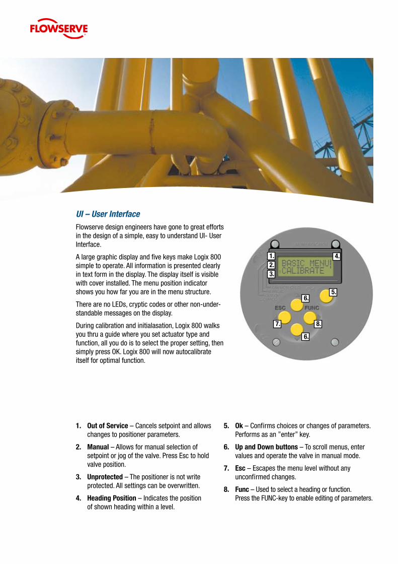
1. OutofService – Cancels setpoint and allows changes to positioner parameters.
2. Manual – Allows for manual selection of setpoint or jog of the valve. Press Esc to hold valve position.
3. Unprotected – The positioner is not write protected. All settings can be overwritten.
4. HeadingPosition – Indicates the position of shown heading within a level.
UI – User InterfaceFlowserve design engineers have gone to great efforts in the design of a simple, easy to understand UI- User Interface.
A large graphic display and five keys make Logix 800 simple to operate. All information is presented clearly in text form in the display. The display itself is visible with cover installed. The menu position indicator shows you how far you are in the menu structure.
There are no LEDs, cryptic codes or other non-under-standable messages on the display.
During calibration and initialasation, Logix 800 walks you thru a guide where you set actuator type and function, all you do is to select the proper setting, then simply press OK. Logix 800 will now autocalibrate itself for optimal function.
5. Ok – Confirms choices or changes of parameters. Performs as an ”enter” key.
6. UpandDownbuttons – To scroll menus, enter values and operate the valve in manual mode.
7. Esc – Escapes the menu level without any unconfirmed changes.
8. Func – Used to select a heading or function. Press the FUNC-key to enable editing of parameters.
1.2.3.
4.
5.6.
6.
7. 8.

CommunicationLogix 800 is available with HART®, Profibus PA, and Foundation Fieldbus protocol for bi-directional communication, enabling remote configuration and initialisation from PC or a Handheld communicator. Drivers are available for AMS software.
A PC configurator for HART® is available free of charge from PMV. All you need is a HART® modem to connect the Logix 800 to your computer. The configurator offers you possibility to select cam functions, do a stroke test among many other functions.
Dimensional Drawings

Logix 800 Digital Positioner
Rotation angle Min. 30° max. 100°, optional 270°
Stroke 5–130 mm (0.2" to 5.1")
Input signal 4–20 mA
Air supply 2–7 bar (30–105 psi) Free from oil, water & moisture, filtered to min. 30 micron.
Air delivery 350 nl/min (12 scfm)
Air consumption <0.3 nl/min (0.01 scfm)
Air connections 1/4" G or NPT
Cable entry 3 x M20 x 1.5 or 1/2" NPT
Electrical connections Screw terminals 2.5 mm²/AWG14
Linearity <1%
Repeatability <0.5%
Hysteresis <0.4%
Dead band 0,2–10% adjustable
Display Graphic, view area 15 x 41 mm (0.6 x 1.6”)
UI 5 push buttons
Processor 16 bit, M 16C
CE directives 93/68/EEC, 98/37/EC, 89/336/EEC, 72/23/EEC, WEEE 2002/967EC
EMC EN 50081-1, EN 50082-2
Voltage drop 8 V (400 Ohm) non-Hart, 9,4 V (470 Ohm) Hart
Vibrations <1% up to 10g at frequency 10–500 Hz
Enclosure IP66/NEMA 4X
Material Die–cast aluminium, A2/A4 fasteners
Surface treatment Powder epoxy
Temperature range –30°C to +80°C (–22°F to 176°F)
Weight Logix 800, 1.4 kg (3 lbs) Explosion proof, 3 kg (6.6 lbs)
Mounting position Any
Optional plug in module
MechanicalSwitches
Type SPDT
Size Sub Sub miniature
Rating 100 mA/ 30 V DC/ 42 V AC
NamurSensors
Type Proximity DIN 19234 NAMUR
Load Current <1mA >3 mA
Voltage range 5–25 V DC
Hysteresis 0,2%
Temp –20°C to 85°C (–4°F to 185°F)
ProximitySwitches
Type SPDT
Rating 100 mA/ 30 V DC/ 42 V AC
Operating time 0,7 ms
Breakdown voltage 200 V DC
Contact resistance 0,1Ω
Mechanical/electrical lifte
> 50x106 operations
4–20mATransmitter
Supply 9–28 V DC
Output 4–20 mA
Resolution 0,1%
Linearity full span +/– 0,5%
Output current limit 30 mA DC
Load impedance 800Ω @ 24 V DC
Alarmoutput
Alarm output Transistor Ri 1KΩ
Alarm Supply Voltage 8–28 V

Logix 800 Series CodingBASE POSITIONER MODEL
Logix 8 A B - CC - D E FF G H - I J - LL M
Digital positioner, LCD displayA= Communication 1 4-20 mA, No communication 2 HART, 4-20 mA 3 Profibus PA 4 Foundation FieldbusB= Electronic hardware options 0 Standard statistics 1 On board pressure sensorsCC= Certifications 02 Intrinsically Safe (ATEX) 14 General Purpose 15 Explosion proof (FM/CSA, ATEX) 16 Explosion proof (FM/CSA, ATEX), direct mounting to FlowactD= Housing W Flowserve: Aluminum, Black w/ white cover (no indicator on CC 15,16) B Flowserve: Aluminum, Black w/ black cover (no indicator on CC 15,16) E Stainless Steel enclosure (only if CC = 15 or 16 )E= Threaded connections N 1/4”NPT air, 1/2”NPT electrical x 2 G 1/4”G air, M20 x 1,5 electrical x 2 M 1/4”NPT air, M20 x 1,5 electrical x 2FF= Feedback shaft, spindle 39 Standard - D shaft incl.nut. S39 23 Standard VDI/VDE 3845 Rotary shaft, S23 21 NAF, S21G= Operating temperature S Standard -30°C to 80°C (-22°F to 176°F)H= Language (Display, IOM) E EnglishI= Cover and indicator S Standard, 30-90 deg, arrow indicator E Extended travel, 270 deg.J= Special options E Single acting version L Single acting, Fail Freeze P Single acting, Fail freeze remote mounted M Single acting, remote mounted S Double acting, general purpose K Double acting Fail freeze function Q Double acting Fail freeze function, remote mounted R Double acting Remote mountedK= Limit switches + Feedback options 0 No switch option T 4-20 mA position feedback + alarm 1 Mec. limit switch + 4-20 mA + alarm (not available for expl. proof version CC=15,16) 2 Reed switch + 4-20 mA + alarm (not available for expl. proof version CC=15,16) 3 Namur V3 type prox. switch,P+F NJ2-V3-N,+4-20 mA+alarm (not for ex. version CC=15,16) 4 Slot type Namur sensor, P+F SJ2 S1N (Not for version CC=15,16) 5 Slot type Namur sensor, P+F SJ2 SN (Not for version CC=15,16) 6 Slot type Namur sensor, P+F SJ2N (not for version CC=15,16)AUXILIARY OPTIONS
LL= Manifold options XX No manifold GM Gauge manifold (gauge ports included in expl. proof version CC=15, 16)M= Gauge options 0 No gauges 1 Output, PSI/BAR/KPA Stainless with brass internals 2 Output + Supply, PSI/BAR/KPA Stainless with brass internals 3 2xOutput + Supply, PSI/BAR/KPA Stainless with brass internals 4 Output, PSI/BAR/KPA Stainless with stainless internals 5 Output + Supply, PSI/BAR/KPA Stainless with stainless internals 6 2xOutput + Supply, PSI/BAR/KPA Stainless with stainless internals
For further spindles and options, please contact PMV!

Flowserve Corporation has established industry leadership in the design and manufacture of its products. When properly selected, this Flowserve product is designed to perform its intended function safely during its useful life. However, the purchaser or user of Flowserve products should be aware that Flowserve products might be used in numerous applications under a wide variety of industrial service conditions. Although Flowserve can (and often does) provide general guidelines, it cannot provide specific data and warnings for all possible applications. The purchaser/user must therefore assume the ultimate responsibility for the proper sizing and selection, installation, operation, and maintenance of Flowserve products. The purchaser/user should read and understand the Installation and Maintenance (I & M) instructions included with the product, and train its employees and contractors in the safe use of Flowserve products in connection with the specific application.
While the information and specifications contained in this literature are believed to be accurate, they are supplied for informative purposes onlyand should not be considered certified or as a guarantee of satisfactory results by reliance thereon. Nothing contained herein is to be construedas a warranty or guarantee, express or implied, regarding any matter with respect to this product. Because Flowserve is continually improving andupgrading its product design, the specifications, dimensions and information contained herein are subject to change without notice. Should any question arise concerning these provisions, the purchaser/user should contact Flowserve Corporation at any one of its worldwide operations or offices.
©2007 Flowserve Corporation, Irving, Texas, USA. Flowserve and PMV are registered trademarks of Flowserve Corporation.
PalmstiernaInternationalABKorta Gatan 9SE-171 54 SolnaSWEDEN Tel: +46 (0) 8 555 106 00Fax: +46 (0) 8 555 106 01E-mail: [email protected]
FlowserveMandersheidtstrasse 1945141 EssenGERMANYTel: +49 (0) 201 8919 5Fax: +49 (0) 201 8919 662
Flowserve12, av. du Québec91965 Courtaboeuf CedexFRANCETel: +33 (0) 1 60 923 251Fax: +33 (0) 1 60 923 299
FlowserveAmbachtsstraat 15 3176 PR Poortugaal THE NETHERLANDSTel: +31 (0) 10 254 1050 Fax: +31 (0) 10 254 1055
FlowserveKassernengasse 69500 Villach, CarinthiaAUSTRIATel: +43 (0) 424241 181 0Fax: +43 (0) 424241 181 50/51
FlowserveVia Prealpi, 3020032 Cormano (Milano)ITALYTel: +39 (0) 2 663 251Fax: +39 (0) 2 615 18 63
FlowserveAv. Dr Antunes Guimaraes 1159Porto 4100-082PORTUGALTel: +351 22 619 8770Fax: +351 22 619 7575
Flowserve1350 N Mt. Springs Prkwy.Springville, UT 84663USATel: +1 801 489 8611Fax: +1 801 489 3719
FlowserveUnit 1, 12 Director RoadSpartan Ext. 21613 Kempton Park, GautengSOUTH AFRICATel: +27 (0) 11 397 3150Fax: +27 (0) 11 397 5300
FlowserveNo. 12 Tuas Avenue 20REPUBLIC OF SINGAPORE 638824Tel: +65 (0) 687 98900Fax: +65 (0) 686 24940
FlowserveC/O Saleh & Abdulaziz AbahsainP.O Box 209Al Khobar 31952SAUDI ARABIATel: +9663 857 3442Fax: +9663 859 5284
FlowserveHanwei BuildingNo. 7 Guanghua RoadChaoYang District100004 BeijingCHINATel: +86-10-592 106 00Fax: +86-10-656 127 02
www.pmv.nu
p/n: FCD PMENBR0002-02
HazardousLocations
Intrinsicallysafe: II 1 GD EEx ia IIC T4 Nemko 03ATEX110X
Explosionproof: CSA, FM Div.1, Class 1, Group B,C,D II 2 GD EEx d IIB+H2 T6 Nemko 03ATEX111
Rätt
Grafi
ska
AB O
rder
nr: 1
9078