localized deformation in irradiated austenitic steels
TRANSCRIPT

Light Water Reactor Sustainability R&D Program
LOCALIZED DEFORMATION IN
IRRADIATED AUSTENITIC STEELS
ORNL: M.N. Gussev*, K.G. Field, J.T. Busby, K.J. Leonard,
PNNL: T.S. Byun,
University of Michigan: K.J. Stephenson, G.S. Was.
1
*Oak Ridge National Laboratory Fuel Cycle & Isotopes Division P.O. Box 2008, MS-6151 Oak Ridge, TN 37831, USA Tel. (865) 574-44-56 Fax. (865) 241-3650 [email protected]

Credits
This presentation is based on several papers and conference talks presented/published recently. Some of these are listed below:
SEM-EBSD and TEM analysis of stress corrosion crack initiation sites in neutron-irradiated austenitic stainless steels, M.N. Gussev, K.G. Field, J.T. Busby, K.J. Stephenson, G.S. Was, 17th International Conference on Environmental Degradation of Materials in Nuclear Power Systems – Water Reactors August 9–12, 2015, Ottawa, Ontario, Canada.
K.J. Leonard, M.N. Gussev, J. Stevens, J.T. Busby, Characterization of Materials Properties and Crack Propagation Mechanisms in Damaged Alloy 718 Leaf Springs Following Commercial Reactor Exposure, 17th International Conference on Environmental Degradation of Materials in Nuclear Power Systems – Water Reactors August 9–12, 2015, Ottawa, Ontario, Canada.
Deformation localization and dislocation channel dynamics in neutron-irradiated austenitic stainless steels, M.N. Gussev, K.G. Field, J.T. Busby, Journal of Nuclear Materials 460 (2015) 139–152.
2

Background: SCC (1)
3
• SCC is often shown schematically as a confluence of stress, material parameters and environment factors.
• Strongly non-linear process with many contributing variables.
Loading direction
Stress
Environment
Microstructure
SCC
Protective oxide rupture
In-crack chemistry
Stress/strain at the crack tip
Mass transport

Background: IASCC (2)
4
• Nuclear reactor is very harsh environment with a complex combination of stress, temperature, and radiation fields, which vary in time.
• Material structure changes under irradiation producing a number of specific phenomena.
Stress
Environment
Microstructure
SCC
Protective oxide rupture
In-crack chemistry
Stress/strain at the crack tip
Mass transport
Irra
dia
tio
n
Radiation hardening and embrittlement
Deformation localization
Radiation-induced segregation at grain
boundaries
• Concept of SCC immunity is attractive; however that immunity rarely exists.
• One can expect the IASCC incidence will increase with time.

An example of low IASCC predictability
5
Leonard K.J. et al, JNM, 2015.
• Well-known, trusted, and (as was thought) well-understood 718-alloy demonstrated stress-corrosion cracking under LWR conditions.
• A full post-irradiation examination performed on irradiated components assemblies showed damage following in-service exposure.
• According to the preliminary conclusion, the IASCC was caused by combination of stress level above yield stress (which was not a sole reason) and slightly decreased amount of delta-phase.
• It is important that all damaged and non-damaged components were produced within the same specification.

Deformation localization in the irradiated
materials (1)
6
Non-irradiated 304 steel, 6% strain 304 steel, 4.4 dpa, 0.8% plastic strain
Non-irradiated steel demonstrates multiple, fine slip lines.
Irradiated steel has significantly smaller slip line density (orders of magnitude!) and the slip lines are more pronounced; their height at the surface is much higher.

Deformation localization in the irradiated
materials (2)
7
304 steel, 4.4 dpa, 0.8%
• Dislocations interact with radiation-induced defects, sweeping them out.
• The defect removal process results in a clear, defect-free pathway for the following dislocations (positive feedback loop).
Regular pattern of dislocation channels in irradiated 304L SS (after Sauzay et al., JNM, 2010).
SEM TEM

Localized deformation (1)
8
304 steel, 4.4 dpa, 0.8%
• For bulk material, a simplified classical approach predicts dislocation accumulation at the grain boundary, formation of dislocation pile-up (under certain conditions), and the appearance of area with increased stress level.
• At the surface, channels may lead to protective film rupture and local corrosion and dissolution.
SEM GB
Pile-up
High stress area

Localized deformation (2)
9
304 steel, 4.4 dpa, 0.8%
• However, the reality is much more complex.
• “Pure channels” and “pile-ups” are, as a rule, extremely simplified terms.
• Highly-deformed areas (“hot spots”) may appear near the grain boundary (our recent finding).
• Dislocation channel may contain deformation twins (material with different crystallography orientation!). And - deformation twinning is not limited by near-room temperature range.
“Classical” channels
Field K.G. et al, JNM, 2014
Hot-spot - Surface Hot-spot – Cross-section

Light Water Reactor Sustainability R&D Program
LOCALIZED DEFORMATION AND IASCC
Presented at the Environmental Degradation Conference, Ontario, Canada, August, 2015
10

Background and objectives
11
• A set of austenitic alloys (>10) was irradiated in the BOR-60 fast reactor up to 47 dpa.
• Constant-extension-rate tensile tests (CERT) conducted previously (K. Stephenson, JNM, 2014) revealed multiple cracks in neutron-irradiated 304 steel specimens tested in a primary water (PW) environment.
• High crack density implied that crack nucleation occurred readily, but crack growth was suppressed (which was unusual!).
• The goal of this work was to investigate crack morphology (size, depth), crack propagation mechanisms, other corrosion-related phenomena, and the correlation between the deformation localization and IASCC.
• Particular focus was made on crack initiation aspects.
Loading direction
A-alloy, 304L SS, 10.2 dpa

Strategy of the irradiated material use
12
• Since the irradiation experiments are expensive, the irradiated materials and specimens are invaluable. It is important to use each specimen in the most efficient way.
• For example, pre- and post-test cutting was considered to supply material and samples for additional research activity. The BOR-60 tensile bars were cut prior the CERT-IASCC tests providing small slices (4 per tensile specimen) for bend and indentation tests, TEM, and additional IASCC tests. After the CERT tests, the bars were cut again providing additional small samples for future use.
• Some publications:
• L. Tan, J.T. Busby: Alloying effect of Ni and Cr on irradiated microstructural evolution of type 304 stainless steels, JNM, 2013.
• K.G. Field et al, Defect sink characteristics of specific grain boundary types in 304 stainless steels under high dose neutron environments, Acta Materialia, 2015.
• M.N. Gussev et al, Magnetic phase formation in irradiated austenitic alloys, JNM, 2014.
4 extra samples prior, and 2 – after the CERT

CERT testing details
13
• Constant extension rate tensile (CERT) tests performed at the University of Michigan in simulated LWR environment.
• Strain rate 𝜀 = 3.5x10⁻⁷ s-1. • Samples strained to failure
without interruption. Control Panel
& Water Columns
Autoclave
& Loading System
Environment Dissolved
Gas Chemical Addn. Conductivity Potential
320C PWR PW
3 ppm H2
1000 ppm B, 2 ppm Li
20.5 µS/cm -860 mVSHE
Specimen geometry

Materials investigated: composition and structure
14
Alloy Type Dose,
dpa Mn Si Cr Ni Mo C N
Grain size,
m
A Commercial
AISI 304L 10.2 1.82 0.56 19.95 10.8 0.53 0.023 0.072 38
SW Commercial
AISI 304L 4.4 1.07 0.24 18.42 10.45 n/d 0.022 0.025 67
A SW
Left: structure of irradiated A-alloy prior CERT test, light microscope, 400×. Black arrows point to retained ferrite grains. Right: structure of irradiated SW-alloy prior CERT test, light microscope, 400× (electrolytic etching with 10% oxalic acid at 6 V for 60–80 s for both A- and SW-alloys).

EBSD details
15
a) Tensile round bar holder (1) with a tubular fixture (2) and dummy specimen (3). A small additional grip (4) may be used to hold the grids for FIB-TEM specimens. b) Surface of the irradiated specimen (SW-alloy) after testing. The white rectangle shows an area that can be EBSD scanned without specimen rotation operations. c) A typical EBSD scan of the cracked area.
Scanning electron microscopy (SEM) was performed using a JEOL JSM 6500F microscope running at 20 kV; working distance was 12 to 15 mm. Prior to EBSD analysis, corrosion products were chemically removed from sample surfaces. Special holder was designed to handle round tensile bars allowing for the analysis of the whole surface. The specimen tensile axis was always aligned with the TD (horizontal) axis of the EBSD system. Due to surface erosion and strain-induced relief, the EBSD analysis was limited by areas with low local strain.
c

Materials investigated: texture
16
A SW
Typical texture plots for the investigated materials. The Inverse Pole Figures (IPFs) generated from EBSD technique are shown with respect to the straining direction during the CERT test.
• Both steels had a typical annealed austenite structure. • No signs of pre-irradiation cold-work or post-irradiation
deformation. • Relatively weak texture (just ~1.9× random for the given loading
direction). • SW-alloy had a slightly increased fraction of soft grains (i.e., grains
with a high Schmid factor) compared to the A-alloy
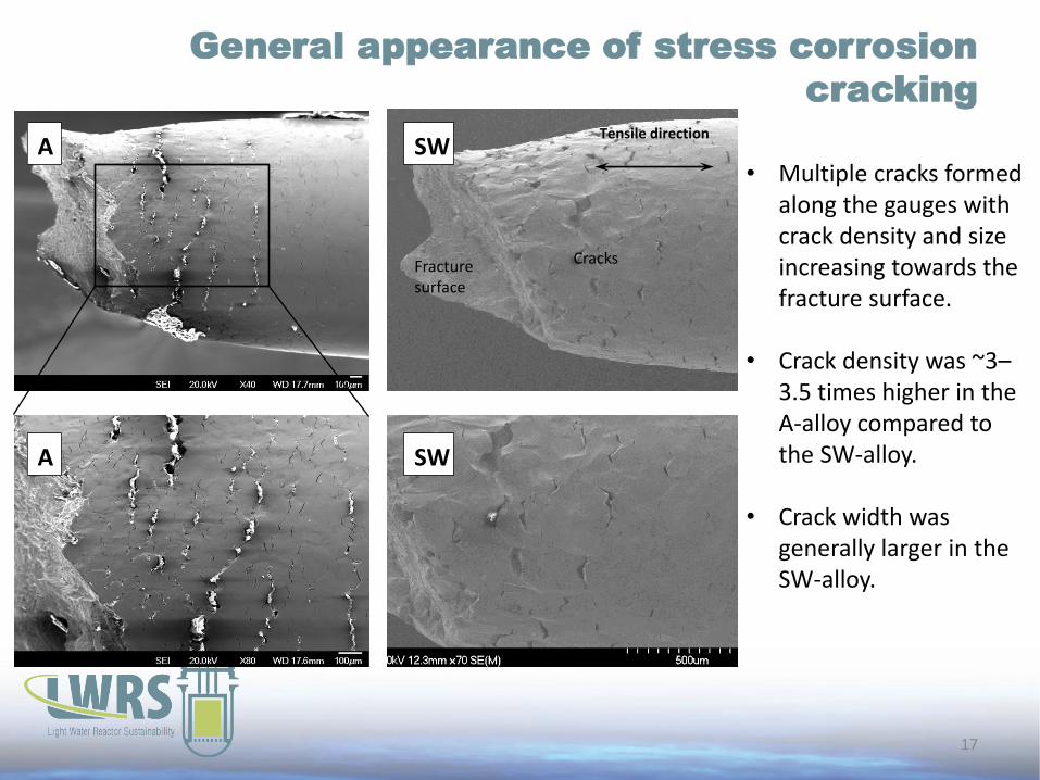
General appearance of stress corrosion
cracking
17
A SW
A SW
• Multiple cracks formed along the gauges with crack density and size increasing towards the fracture surface.
• Crack density was ~3–
3.5 times higher in the A-alloy compared to the SW-alloy.
• Crack width was generally larger in the SW-alloy.
Fracture surface
Cracks
Tensile direction

Relationship of local strain and cracking
18
Surface of the deformed tensile bar with the strain levels shown (A-alloy).
The local strain was calculated as =(d0
2/di2) –1, where di and
d0 are current and initial diameters, respectively. Cracks appeared at the surface at local strain of ~0.6%; below this strain level, only dislocation channels were observed at the surface and no cracks. So, crack initiation required some plastic strain level (or, some critical dislocation channel height).
Tensile direction

Surface appearance in BSE mode
19
SE BSE
AS19 specimen, the same area in secondary electrons (SE) and back-scattered electrons (BSE).
Dislocation channels had a pronounced contrast in the SEM-BSE images. Sometimes channels (black arrows) were invisible in secondary electron (SE) mode but clearly visible in BSE, i.e. step height and surface roughness were not responsible for the contrast.
Localized oxide distribution near a crack initiation site in SW-alloy
Tensile direction
Tensile direction

Oxidation of dislocation channels?..
20
SEM BSE image of the A-alloy specimen gauge after CERT test
Dislocation channels in BSE mode often appeared as wide smooth-edged lines edges. It was assumed that the BSE-contrast may be caused by element contrast and presence of oxides (light elements/oxides are “darker”), not by surface topology only. After cleaning many channels revealed the eroded surface suggesting specific oxidation processes. It was decided to prepare FIB-lift out samples to analyze oxidation in more detail.
Tensile direction
Cracked grain boundary and slip lines at the surface (70-degree tilted image). One can see step caused by dislocation channels (black arrows). The surface is eroded along some channels (white arrows). A-alloy.
BSE, no cleaning SE, after cleaning

FIB-TEM analysis of oxide layers
21
High-angle annular dark field (HAADF) image, EDS element maps, and color-overlay maps of a dislocation channel showing localized corrosion at the base of the surface step (top) and a dislocation channel showing limited attack at the base of the surface step (bottom).
The local corrosion damage associated with defect-free channels was observed. Two different oxide morphologies are noted, the first being a Cr-rich oxide along the unperturbed surface and at the top of the erosion pocket and a Cr-depleted oxide protruding into the base metal at the base of the erosion pocket.

Crack morphology and dimensions
22
• Average crack length was ~150-200 m; larger crack formed via plastic strain and coalescence.
• Average crack depth was 80-100 m.
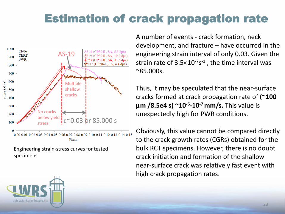
Estimation of crack propagation rate
23
Engineering strain-stress curves for tested specimens
AS-19
No cracks below yield stress
Multiple shallow cracks
A number of events - crack formation, neck development, and fracture – have occurred in the engineering strain interval of only 0.03. Given the strain rate of 3.510-7s-1 , the time interval was ~85.000s. Thus, it may be speculated that the near-surface cracks formed at crack propagation rate of (~100 m /8.5e4 s) ~10-6-10-7 mm/s. This value is unexpectedly high for PWR conditions. Obviously, this value cannot be compared directly to the crack growth rates (CGRs) obtained for the bulk RCT specimens. However, there is no doubt crack initiation and formation of the shallow near-surface crack was relatively fast event with high crack propagation rates.
~0.03 or 85.000 s

EBSD analysis of a typical crack
24
G2
G1 G4
G3 G7
G5 G6
IPF IQ GROD
Sf SEM
#2
#3
#1
#3
#1
#2
Strain direction
G3
G1
G4
G2
G7
G5 G6
Multiple crack provided an opportunity to accumulate large enough statistics on crack initiation. Using SEM-EBSD, the orientation of crack-adjacent and neighbor grains was investigated in detail as well as Schmid factor, in-grain misorientation, and morphology of dislocation channels. Since grain orientation with respect to the tensile axis defines its elastic properties, Schmid factor, etc., thus it was possible to expect that grain orientation influences also crack initiation.

Crystallographic orientation patterns for
the crack-adjacent grains
25
Crack
Short cracks (1-2 GBs)
Grain orientation data for relatively large crack (L) in A-alloy. Local strain value ~2.3%.
• Crack initiation is not a random process. Grain orientation strongly influenced the appearance of stress corrosion cracks.
• For short cracks, one or both grains adjacent to the cracked GB were often oriented close to the center of the unit triangle (softest grains) or close to the [111]-corner.
• Grain orientation role became less pronounced for long cracks. Widest portion of the crack (i.e. crack initiation location) still tended to follow the rule discussed above; however, grain selectivity became weaker with crack length increase.

The scheme of triangle partitioning
26
To analyze the role of grain orientation, the unit triangle was arbitrarily divided into four areas: • The [001]-area contained
grains oriented close to the [001]-corner and with the lowest elastic stiffness.
• Grains oriented close to the [111]-corner had the largest elastic stiffness and the lowest Schmid factor.
• Grains from the [S]-area were mainly the softest grains with a high Schmid factor.
Loading direction

The role of grain orientation on crack
initiation
27
Partition Fraction in
material
Cracked
fraction
Cracking intensity
(Fraction involved in
cracking/Total fraction)
SW-alloy
[001] 0.115 0.03 0.272
[S] 0.502 0.563 1.120
[111] 0.242 0.344 1.423
[101] 0.141 0.063 0.443 Total 1 1 –
A-alloy
[001] 0.161 0.114 0.708
[S] 0.422 0.543 1.288
[111] 0.314 0.343 1.092
[101] 0.103 0 0 Total 1 1
For the studied specimens, the largest cracking intensity was observed for grains belonging to the [111]-partition and for the softest grains. Grains from [001]- and [010]-partitions were much less frequently involved in cracking.

Conclusions
28
• IASCC and deformation localization in the irradiated austenitic steels are close related phenomena. There are a lot of nuances related to crack initiation and propagation stages, but according to our results, plastic strain and cracking often co-existed in the same objects.
• As an example, the stress corrosion crack initiation was investigated for two AISI 304L steels irradiated by neutrons to 4.4–10.2 dpa and CERT-tested in primary water (PW). While loading under these conditions, multiple cracks appeared at the surface, with intergranular cracking as a dominant mechanism.
• It was shown that crack initiation required some preliminary plastic deformation, estimated as ~0.6%.
• Additionally, dislocation channels at the surface in PW-conditions might be sensitive to specific corrosion damage; some channels experienced oxidation along the slip plane.
• Grain orientation is an important factor influencing crack initiation. Grains oriented close to the [111] (with respect to the tensile direction) and the softest grains with a high Schmid factor were most often involved in crack initiation. Grains oriented close to [001] and [101] were much less sensitive to crack initiation.

10/22/09 STEP Integration Workshop 1 29