local road design standards - kwazulu-natal ... local road design standards 8.1 introduction r oad...
TRANSCRIPT

8 LOCAL ROAD DESIGN STANDARDS
8.1 Introduction Road designstandards and literature in South Africa
generally do not address the type of rural Local
Roads under consideration in this report and very
little documentedguidanceis available to establish suitable
standards for local conditions. Rural Local Roads of this
type are often referred to as 'non-engineered' and are
usually constructed without formal design drawings other
than a typical cross-sectionand drainage standards, relying
on the experienceof the engineers and machine operators
involved.Hence in order to establish design standards it is
therefore necessary to return to basic principles and to
focus on the primary objectives of the programme. The
following issues needto be addressed in the development
of appropriate standards:
. All weather accessibility
Restricted budgets
Labour enhanced construction and maintenance
possibilities
Limited maintenance
.
Low traffic volumes
To reach as many communities as possible.
The intentionof this section of the report is thus to draw up
guidelines based on local experience, addressing the
above issues. These guidelines should not be seen as
being prescriptive, but merely the first step in establishing
standards which have an emphasis on accessibility and
affordability, and which in due course may be modified as
implementationproceeds. The guidelines are not meant to
replacegood engineeringjudgement but should assist in a
more uniform approach to implementation.
- 8.1 -

8.2 Network Hierarchy
"Local Roads may be defined asthose rural roads which do not
qualify as District or Main Roads, butprovide access from a proclaimed
road to public infrastructure such asschools, clinics and communityfacilities, or provide access to asettlement of a minimum of 50
persons or at least 5 homesteads."
Historically, Community Access Roads in KwaZulu-
Natal have not been recognised as forming an
integralpart of the Provincial road network, with the
result that they were not funded by the road authorities.
Their importance has nevertheless been highlighted over
recentyears. The need for all weather access is invariably
voiced by ruralcommunitiesas being of primary importance
to their well-being and upliftment.
Local Roads are therefore the vital link between
communities and the formal road network and while they
may form the lowest level in the road hierarchy, they are
just as important to the community as the recognised road
network. In terms of the road network they are frequently
characterisedby their discontinuity Le. 'the end of the road'.
They function primarilyas collector roads to the formal road
network, servicing community facilities along the route.
The roads have frequently developed from tracks in the
veld, which are generally not built to any formal geometric
standard,nor do they have proper drainage. As difficulties
arise with one track, so another is established which leads
to a proliferation of tracks, and inevitably results in some
degree of soil erosion and environmental damage.
It is therefore important that any road improvement be
assessed and planned to meaningfully connect into the
formal road network and that where possible, continuity is
established to open up areas and to link up communities.
Thiswill assistin developingnew markets and opportunities
for communities that have previously been isolated from
each other and from their rural centres.
In terms of a road hierarchy, Local Roads may be defined
as those rural roadswhich do not qualify as District or Main
Roads,but provideaccessfrom a proclaimed road to public
infrastructure such as schools, clinics and community
facilities, or provideaccessto a settlement of a minimum of
50 persons or at least 5 homesteads.
- 8.2-
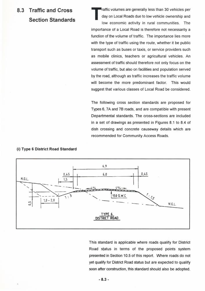
8.3 Trafficand Cross
Section Standards
(i)Type 6 DistrictRoad Standard
N.G.l.V,l.s
1.5"-" :--- - - -----
<I'!.<::> ~
Trafficvolumes aregenerally less than 30 vehicles per
day on Local Roadsdue to lowvehicle ownership and
low economic activity in rural communities. The
importance of a Local Road is therefore not necessarily a
function of the volume of traffic. The importance lies more
with the type of traffic using the route, whether it be public
transport such as buses or taxis, or service providers such
as mobile clinics, teachers or agricultural vehicles. An
assessmentof traffic should therefore not only focus on the
volume of traffic, but alsoon facilities and population served
by the road,although as traffic increases the traffic volume
will become the more predominant factor. This would
suggest that various classes of Local Road be considered.
The following cross section standards are proposed for
Types6, 7A and 78 roads, and are compatible with present
Departmental standards. The cross-sections are included
in a set of drawings as presented in Figures 8.1 to 8.4 of
dish crossing and concrete causeway details which are
recommended for Community Access Roads.
6,9
6,0 V,lts
-4 °/0 4°/0--
.........150G.W.C
N.G.L.-- -- -
TYPE 6DISTRIcTROAD
This standard is applicable where roads qualify for District
Road status in terms of the proposed points system
presentedin Section10.5of this report. Where roads do not
yet qualify for DistrictRoadstatus but are expected to qualify
soon after construction,this standardshould also be adopted.
- 8.3-

(ii) Type 7A Local or By-Road Standard (DesirableStandard)
5.9
N.G.l.5,0 0,45
_4 % I, 0/0-
~I. -----1150 GWC - -- .--
N.G.L
MEADOWDRAIN.WHERE EARTHWORKSMATERIAl REO.UJRED
TYPE 7ALOCALROADOR BY-ROAD(DESIRABLESTANDARDI
This standard is applicable to roads which are not likely to
be proclaimed as District Roads in the foreseeable future,
according to the points system, but merely serve as
access to and between communities. It is expected that
the majority of Local Roadswill be constructed to this
standard.
(iii) Type 7B Local or By-
Road Standard (Minimum
Standard)
3.9
0,45~- --- ~' /. -, 0 0
P . ~.5' -:- -.-1. '/0 4/"0- 1/.,- I - './", ~.~,- - 25G.W.c. - N.GL
lJ1 11.-1?\ . .MEADOWDRAIN/ 0-WHEREEARTHWORKS GRAVEL MAYBE REDUCEDMATERIAl REQUIRED TO 100mm THICKNESS
3,0 0,45N.G.L.
TYPE 7BLOCALROADOR BY-ROAD(MINIMUM STANDARD)
In terrain of steep crossfall or where traffic volumes are
expected to be Iow, consideration could be given to
reducing a Type 7A cross section to a Type 78 cross
- 8.4-

8.4 Geometric Design8.4.1 General
8.4.2 Earthworks
8.4.3 Horizontal and Vertical
Alignments
section as indicated below. This willbring about a saving
in earthworks, drainage and gravelling costs and so allow
a longer length of road to be constructed. Passing
opportunities willneed to be provided at regular intervals
and wideningwillbe necessary on sharp bends. Widths
could alternate between a Type 7A and Type 78 cross
section as prevailing conditions change.
The horizontal and vertical alignment of Local Roads
should generally followthe alignment of existing
tracks, as suggested by the prevailingtopography.
Circular curves should nevertheless be properly set out and
the intention should be to achieve balanced alignment
parameters between vertical and horizontal alignments as
are applied fOfhigher order roads. The followingguidelines
are proposed as minimumstandards although
circumstances may dictate otherwise. Where they cannot
be adhered to, other precautionary measures may have tobe taken.
Earthworks should in general be kept to a minimum
without compromising drainage requirements and side
borrowis preferred to the hauling of earthworks.
Where roads could become DistrictRoads in the
foreseeable future, they should be constructed to District
Road standards, which is more or less to a 60 km/h
design speed. An average travelling speed of 30 km/h
is the acceptable norm for Local Roads. Minimumcurve
radii are proposed as follows:
Terrain Type
Mountainous
Radius (m)
15
50
90
130
Hilly
RollingFlat
Where possible, the followingminimurrastopping sight
distances shou~dbe maintained for Local Roads. Inthe
case of intersections, sharp curves or where pedestrians
- 8.5-

make use ofthe road, they may have to be adjusted
accordingly.
Terrain Type
Mountainous
Hilly
RollingFlat
Minimum Visibility (m)
35
50
70
90
Minimumradius horizontal curves should in general be
avoided on or after crest vertical curves.
Gradients should preferably not exceed 14% and in no
circumstances exceed 20%.
Where gradients in excess of 14% are unavoidable,
consideration willneed to be given to surfacing to avoid
erosion and vehicle traction difficulties.
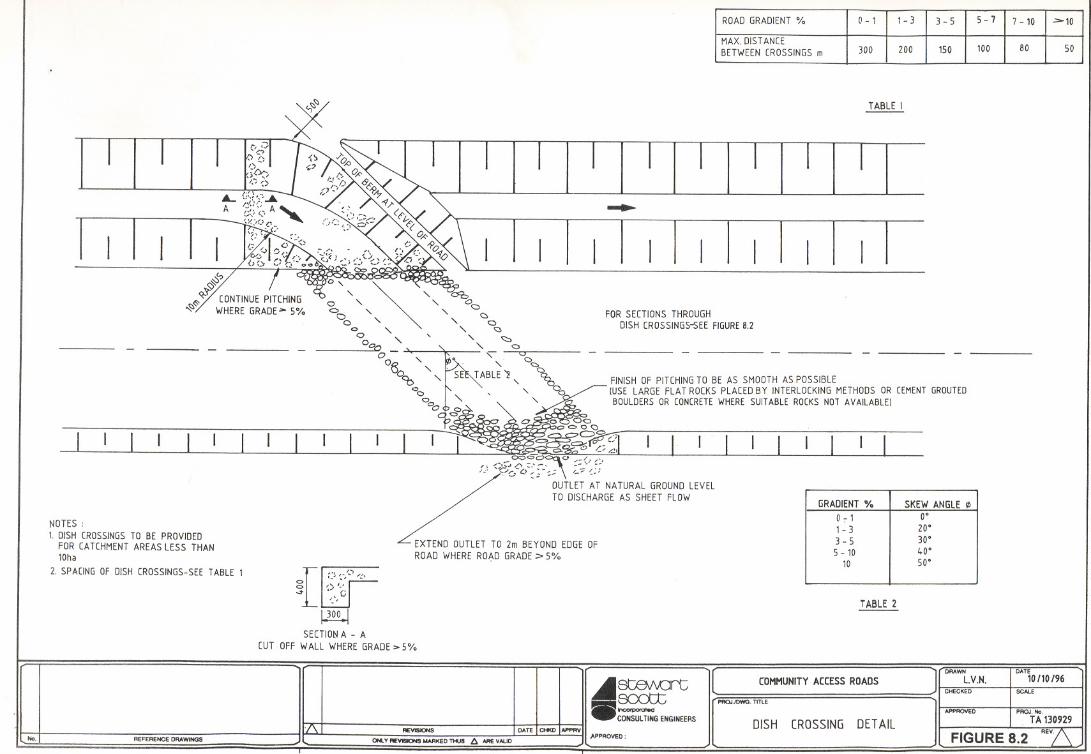
8.5 Drainage
Requirements Careful attention should be given to drainage
requirements and they should in general not be
compromisedto achieve savings, as they invariably
lead to erosion and high maintenance costs.
8.5.1 Road Drainage The requirements of the Department's Betterment and
Gravelling Manual should be consulted for the road
drainage requirements. Where practical, however, dished
crossingsare preferred for the Type 7 roads as opposed to
pipe crossings. Dischargepoints should nevertheless be as
per the Manual.
For catchmentslargerthan 3 hectares considerationmay
have to be givento pipedcrossingsforsafety reasons.
Typical details for dished crossings are included as Figures
8.2 and 8.3.
8.5.2 Riverand Stream
Crossings
River and stream crossings should generally be constructed
as concrete drifts at riverlstreambed level, with suitable cut-
off walls upstream and downstream of the slab where they
- 8.6-

8.6 Road Reserve
8.7 Road Materials
Requirements(i) Earthworks
are not castdirectly onto rock. A typical detail can be seen
in Figure 8.4.
The width of the crossing should be adequate for one lane
of traffic only (Le. 3m), with approach gradients preferably
less than 8% where possible.
Where the base stream flow is expected to be deeper than
50mm over the width of the crossing for most of the year
with flow velocities in excess of about 1 m/s, a vented
crossingshouldbe considered for safety reasons. Concrete
bollardsshouldbe constructedon both sides of the crossing
to demarcate the crossing and to indicate flow depth.
For larger rivers where a box culvert or bridge may be
necessary, the Department's Bridge Engineer should be
consulted.
Where a road could qualify as a District Road, a
2Q-metreroadreservewill have to be secured and
the road aligned accordingly. Any difficulties with
encroachment should be noted and the extent of the road
reserve pointed out to the local community to avoid future
development in the proposed road reserve. This could be
done by means of painted boulders placed at the road
reserve boundary.
For a Type 7B road an informal road reserve width of 10m
is desirable.
Where possiblethe insitusoil and soft rock materials
should be used for earthworks and possibly also
as a ridingsurface,providedthe road is trafficable
in wet weather.
In flatter areas the road should be raised 300 - 500mm
above the surrounding terrain except that in areas of pure
sand the road should not be raised.
- 8.7-

(ii) Gravel Wearing Course
8.8 Community
Liaison
8.9 Conclusion
Where roads will shortly qualify for District Road status, a
150 mm gravel wearing course should be used. For lower
order roads of Type 7 standard, the gravel wearing course
could be reducedin thicknessto between 125 and 100 mm,
depending on conditions. Where the insitu material is
adequatefor all weather travel, no wearing course need be
imported in order to save costs.
Local communities should be advised of the standards
proposed for their road{s) to avoid any
misunderstanding Le. road widths, overtopped
causeways, realignments etc.
The statusof landownershipalong the route will need to be
established, particularly where realignments are proposed
away from the existing tracks. This may require written
agreementfrom landownersor community leadership in the
case of communal lands.
Borrowpits should preferably be finalised before the
commencement of works, particularly where they are
located on communal lands. To avoid any demands for
royalty payments, written agreements from the community
leadershipshouldbe arrangedfor in the case of community
lands.
An open transparent manner should be adopted in matters
affecting the communities and the local Rural Road
Transport Forum needs to be regularly informed of
progress. They should also be consulted on labour related
issues where local labour is to be employed for the
constructionof the road. A project liaison committee could
be considered for these purposes.
The guidelines proposed in this section for the design
of Local Roads should be updated from time to time
andthey should ultimately develop into an extension
of the Department'sproject manuals. Local Road standards
should not be dealt with in isolation but should be
compatible with Main Road and District Road standards.
- 8.8-

rather than on high geometric standards. It is essential
however that safety standards appropriate to low speed
traffic be adopted, and this together with the cost
implications will need to be closely monitored by the sitestaff involved.
The objective is to provide all-weather access to as many
communitiesas possiblewithin the limited budgets, without
compromising particularly on the provision of adequate
stormwater drainage requirements, as deficiencies in this
regard generally cause an increase in maintenance costs
with possible serious adverse environmental implications.
References
1. KwaZulu-Natal Department of Transport, Maintenance Directorate. "Betterment and GravellingManual" October 1996.
KwaZulu-Natal Department of Transport, "Standard Details".
KwaZuluDepartmentof Works. "TribalRoad Upgradingand Maintenance Programme (TRUMP),
Guide Manual, Section 3 : TechnicalProcedures, Draft 1994."
2.
3.
- 8.9-

N.G.l.
"-.......
u:.C> ~
N.G.l.
6,9
0.~5
~- ----.6.0
_4% 4%-
t~50G.W~C-=" -- --TYPE6
DISTRICTROAD
5,9
0,45
1,5-5.0
.......
*Q
MEADOWDRAIN.WHERE EARTHWORKS
MA TERIAL REQUIRED
N.G.L.
~I
_4% 4%-
t~2~--150G.W ---
TYPE 7A~LOCALROADORBY-ROAD
(DESIRABLESTANDARD)
3.9
0,45
-
0,45
N.G.L.
~~rt.incorporatedCONSULTING ENGINEERS
APPROVED:
[PROJ./DWG. TITlE
25 G.W.C-- -
7."!$
GRAVELMAYBE REDUCEDTO 100mmTHICKNESS
TYPE 7BLOCALROADORBY-ROAD(MINIMUMSTANDARD)
COMMUNITYACCESSROADS
TYPICALCROSSSECTIONS
)DRAWN
D.E.L.
CHECKED
M.U.
N.G.l.
DATEOCT1996
SCALE
1:100APPROVED I PROJ. No.
TA 130929. ;;EJ.
FIGURE 8.1 '
-.'0,45 3,0 0,451- 1.5-
-.....:...... - -1+ % 4%-- -,., , . "'
TABLEI
....
~
fj~
~q,.'r' CONTINUEPITCHING~ WHEREGRADE>-5% FORSECTIONSTHROUGH
DISH CROSSINGS-SEEFIGURE8.2
NOTES:1. DISH CROSSINGSTO BE PROVIDED
FOR CATCHMENTAREASLESS THAN10ha
2. SPACINGOF DISH CROSSINGS-SEETABLE 1
[~,')"I_'/..
g ') I~" -',:, C
~SECTIONA - A
CUT OFFWALL WHEREGRADE>5%
TABLE 2
~8tBIvOrt_~NGINEERS
[ COMMUNITYACCESSR~~- -l fORAWNl.V.N.CHECKED
DATE10/10/96
SCAlE
PAOJJDWG. TITlE
No. REFERENCE DRAWINGS AEVISIONS I DATE I CHl<D1-11 APPROYED:ONlY AEV1SIOHS MARKED THUS 6 ARE VALID
DISH CROSSINGDETAILAPPROVED I PAOJ.No
TA130929
FIGURE 8.~
ROADGRADIENT% 0 - 1 1- 3 3-5 5 - 7 7 -10 >-10
MAX.DISTANCEBETWEENCROSSINGSm 300 200 150 100 80 50
GRADIENT% SKEW ANGLE
07 1 O'1- 3 20'3-5 30'5 - 10 40.
10 50.

No. REFERENCE DRAWINGS
~._-
5 000
- - - -2 000
.- -
3 000 2 000
11,% GRADE
1 ~ooJ - ~oo I "" 1 1500 1
~ ~ ~- ~0" - - - - 5% GRADEU""Ne::>
0"0"Ne::>
-- --
11 0001 2 000 I 1 000 IJ 0% GRADE
-----0 "U""Ne::>
.4I~rt'.' "",o.pom.edCONSULTINGENGINEERS
-'~---'
REVISIONS I DATEICHKD IAPPRV" APPROVEDONLYREVISIONSMARKEDTHUS A AREVALID
LUC()MMUNITY ACCESS ROADS]PROJJDWG TITLE
DISH CROSSING
OETAILS OF SELECTIVECROSSSECTIONSFIGURE 8.3
REV
DRAWN DATE
OH. OCT. 1996CHECKED SCALE
M.U. 1:100APPROVED PROJ.No
TA 130929

~ JCONCRETEBOLLARDS
TA ~ 1
C~ ---JC
rB
1: 2 YEAR
~LSTREAMBED
t LEVEL
( " (-"\ I \ I /
- --.:...- -- -_2-::-/
VENTEDCROSSINGONLYWHEREBASE FLOWOVERCAUSEWAYWOULDBE ~ 50mmDEEPAND/OR FLOWVELOCITY>1m/sec.
- " L 200 MIN. (~ \" () ONAVERAGE,- (" "- - -'- -----
/-- SECTIONA-A
~ 500300 t 150 I ~O
!
SCALE1:100
l1li
OETAILS1:20
SECTIONB-B
BD.LLAROSCALE
~~rt'.' '''''''p<><atedCONSULTINGENGINEERS
No. REFERENCE DRAWINGS
REVISIONS I DATEICHKD IAPPRV
ONLV REVISIONS "ARKED THUS 6.ARE VALID
~ REF.261
r- 1: 2 YEARFLOODLEVEL
II
'AT
8% DESIRABLEMAXIMUM
18% ABSOLUTEMAXIMUM
WHEREPOSSIBLEFOUNDON ROCKOTHERWISESUITABLE CUT-OFF WALLSNEEDTO BE PROVIDED.
PROJIOWG TITLE
[ n_- lDRAWN
COMMUNITYACCESSROADS L.V.N.CHECKED SCALE
AS INDICATED
CONCRETECAUSEWAYOETAILS
DATE
25/10/96
APPROVED I PROJ.NoTA130929
FIGURE 8.4 REV