literature presentation - health & performance monitoring using active magnetic bearing
DESCRIPTION
Basic background information on the buildup.TRANSCRIPT

1Challenge the future
AE4020 Literature StudyHealth & Performance Monitoring UsingActive Magnetic Bearing Systems

2Challenge the future
Contents
1. AMB System & Relevance
2. Advantages of using AMBs
3. Principle of operation
4. Objective
5. Remote monitoring using AMBs
6. Fault Classification
7. System modeling approaches
8. Cases to test
9. Additional Research
10. Deliverables
11. Timeline

3Challenge the future
1. AMB System & Relevance
Integration of
• Power Electronics
• Control Systems / Logic
• Rotor Dynamics
• Electromagnetic Technology
• Computing Technology

4Challenge the future
2. Advantages Of AMBs
• Application• No wear, noiseless, no lubrication, large range of
operational temperatures, elimination of path for circulating
currents.
• Control• Active control of imbalance & vibration, can vary stiffness
and damping as required, monitor system performance.
• Performance• Operate in critical environments, no lubrication related
problems, eliminates several components from system,
improved system reliability and longer operating life.

5Challenge the future
3. Principle of Operation

6Challenge the future
3. Principle of Operation (Contd.)

7Challenge the future
4. Objective
To create a health and performance monitoring tool whose deviation – reason matrix will be tested and established using a rotor dynamic model of the system.
Focus:•New key parameter indicators to capture misalignments
•To create a generic deviation – reason matrix for AMBs
•To understand the black box operation of AMBs using rotor dynamics and control – Eg: Machine Vibration

8Challenge the future
4. Objective (Contd.)
Series of Steps
1.Research various ways to develop a robust model – rotor dynamics perspective.
2.Failure mode analysis for AMB systems.
3.Data available and derivation of necessary parameters.
4.Build a deviation – reason matrix based on previous experience.

9Challenge the future
4. Objective (Contd.)
5. Build a rotor dynamic model.
6. Validate the model.
7. Test cases.
8. Add additional diagnostic capability.

10Challenge the future
5. Remote Monitoring using AMBs
Data Available From AMBs in SmartConnect:
• Current (AC, DC)• Rotor Position (Gap)• Coil Temperature• Power Amplifier Temperature• Rotor Unbalance• Flux• Voltage
11Challenge the future
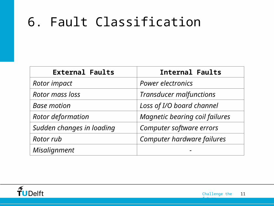
6. Fault Classification
External Faults Internal Faults
Rotor impact Power electronics
Rotor mass loss Transducer malfunctions
Base motion Loss of I/O board channel
Rotor deformation Magnetic bearing coil failures
Sudden changes in loading Computer software errors
Rotor rub Computer hardware failures
Misalignment -

12Challenge the future
7. System Modeling Approaches
• Softwares – Ansys, ROMAC codes, Maple, Matlab / Simulink, FEMM
• Complexity• Rotor – Jeffcott, nDOF
• AMB – N, Ag, I, g, Permeability of medium
• Control Logic – PID, H-Infinity, Mu-synthesis, ADR etc.
• Control System – Centralized, Voltage vs Current
• Rotor / System Dynamics
• Validation

13Challenge the future
8. Cases to Test
• Coil Saturation Dynamics
• Stable Rotordynamics
• Unstable Rotordynamics – Continuous Disturbance
• Unstable Rotordynamics – Disturbance Outside Limits
• Rotor Levitation – Centering
• Effect of increased unbalance – Variation in Current

14Challenge the future
9. Additional Research
• Key aspects of specifying an AMB system• Design Considerations• Rotordynamic Considerations• Diagnostic Considerations
• Real time thrust force

15Challenge the future
10. Deliverables
• Creating new KPI’s – Early detection of incipient faults• Faster capture of machine health deviation
• Easier interpretation of data from the machine
• AMB supported rotor model to explain the “black-box” operation of AMBs.
• Experimentally backed Deviation – Reason Matrix
• How to specify an AMB system for first time users.

16Challenge the future
11. Timeline
• Modeling & Validation – First half of January• Model of Rotor, AMB with advanced controller• Validation with existing results
• Testing cases & result interpretation – Second half of January
• Report, consultation and defense – First half of February

17Challenge the future
THANK YOU
Questions Please!!

18Challenge the future
Fault Classification – Final List
Performance Radial Axial
Fouling Rotor Deformation Change in Vibration
Corrosion Change in Vibration
Coil Saturation
Impeller Damage Coil Saturation
Surge

19Challenge the future
Relationship Matrix - Faults
H – Upper limit violation of indicator value.
L – Lower limit violation of indicator value.
X – Upper or lower limit violation of indicator value.
FAILURE MODES
Loss of Performance
INDICATORS Fouling Corrosion Impeller Damage
Surge
Performanc
e / Process
Indicators
Head Deviation H - H H
Efficiency Deviation H H H H
Outlet Temp.
Deviation
H - H H
Polytropic Efficiency X L X X
General Parameters:

20Challenge the future
Relationship Matrix - Faults
FAILURE MODESRotor Faults Radial
INDICATORS Rotor Deformation
Change in Vibration
Coil Saturation
Current X X H
Position X - X
Unbalance - H -
Temperature - - H
Radial Bearing Parameters:

21Challenge the future
Relationship Matrix - Faults
FAILURE MODESRotor Faults Axial
INDICATORS Change in Vibration Coil Saturation
Current X H
Position - X
Temperature - H
Axial Bearing Parameters:

22Challenge the future
System Modeling
• UVa RotorLab• Rotor Modeling• M, D, K Matrix Extraction• AMB Supported Rotor option
• FEMM – Finite Element Method Magnetics: Core Electromagnet Design• Optimized AMB Design• Magnetic Flux analysis – Number of turns, cross section
shape, position of electromagnets, etc.
• COMSOL Multiphysics & MSC Software – ADAMS, PATRAN• Conflicting license issues

23Challenge the future
System Modeling
• Maple• Solving 2nd order differential equations
• MatLab / Simulink Approaches
• Pure MatLab
• Ansys + MatLab
• Matlab + Simulink
• Pure Simulink

24Challenge the future
System Modeling – Rotor
• Matrices from FEM softwares versus from papers
• More accurate rotor model, more DOF, larger matrix size (102 x 102), slower computation.
• FEM model matrix reduction as compared to simple assembly.
• Cross coupling between AMB system and rotor might not be captured.
• Validation concerns
25Challenge the future
System Modeling – Rotor
• Jeffcott Rotor vs Real Sized
• nDOF
• Mass matrix
• Stiffness matrix
• Damping matrix
• Gyroscopic matrix – When in Motion

26Challenge the future
System Modeling – AMB
• Depth of modeling
• Coils• Number of turns, resistance, inductance
• Cross-sectional area of the electromagnet in the gap
• Current supplied
• AMB Force relation – per electromagnet vs per pair vs per system
27Challenge the future
System Modeling – Control Logic
• Centralized vs Decentralized Control
• Voltage controlled vs Current Controlled
• Simple vs Complex

28Challenge the future
System Modeling – Control Logic
• PID
• PD control logic is simple and most widely applied
• It is better to omit the integral part since it destabilizes control logic in cases of sudden peaks or drops.
• Why then is PID preferred over a simple PD control for a AMB supported rotor model?
• Disadv – Lower frequency & higher nonlinear region

29Challenge the future
System Modeling – Control Logic
• Feedback Linearization
• Back-stepping approach
• Neural Network Control
• Fuzzy Logic Control
• Iterative Learning Control
• Automatic Learning Control

30Challenge the future
System Modeling – Control Logic
• H-Infinity Closed Loop Shaping
• H-Infinity Open Loop Shaping
• Q – Parameterization
• Mu – Synthesis
• ADR
• Sliding mode control

31Challenge the future
System Modeling – Control Logic
• Problems associated with an advanced control logic – a fine line
• Too much control
• Difficult to capture faults
• Adaptive nature might smother the possibility of knowing faults in the machine
• To detect faults or have a system that keeps running even when there are faults.

32Challenge the future
System Modeling – Rotordynamics
• Bode Plots• Frequency response of the system• Effect of changing damping on the system
• Impulse Response
• Transfer Function• Extracting transfer function from the state space
matrices of the system

33Challenge the future
System Modeling – Rotordynamics
• Poles
• Zeros
• Natural Frequency
• Resonant Frequency• Critical Speeds• Structural Resonance

34Challenge the future
System Modeling – Rotordynamics
• Damping Ratio
• DC Gain
• Nyquist Plot
• Eigen Values, Eigen Vectors
• Campbell Diagram

35Challenge the future
5. Series Of Steps
1. Research various ways to develop a robust model that can provide a good representation of the dynamics of the system from rotor dynamics point of view.
2. Research on the various failure mode analysis for a rotor on AMB system.
3. Get a good overview of the system from an operational point of view to understand what parameters are crucial in order to assess the health of the system.

36Challenge the future
5. Series Of Steps (Contd.)
4. Check for what data is available from an AMB system and how the required parameters can be derived from them. Current focus here involves extracting real time thrust measurements and vibration values using rotor properties, data sheets and real time incoming data. Both these parameters can be extracted by developing a relation map between available and design data.• For thrust bearing, a 3-way relation between thrust force, control
current and gap needs to be established.
• For vibration data, a relation will have to be built between current
and position. The interest here is not the vibration seen with the
increased control current but the vibration amplitudes of the rotor
when simply levitated but not controlled. The increasing vibration
trend can provide a good idea of fouling or rotor damage.

37Challenge the future
5. Series Of Steps (Contd.)
5. Build a cause and effect matrix where the failures are matched against the parameter values. This matrix will represent how certain parameter values going out of bound on the upper or lower limit can indicate the incipient faults in the system.
6. Build a rotordynamic model to explain the working of an AMB system along with crucial plots of orbits, Campbell diagram etc. This model will be used to open up the black box operation of the AMB system.
7. Test the matrix validity using case data from sites and the model.
8. Adding additional diagnostic capability by using an algorithm to check for sensor faults. This will be valid only for slow failures or faults in the sensors.

38Challenge the future
Case Studies
• Coil Saturation Dynamics
• Stable Rotordynamics
• Unstable Rotordynamics – Continuous Disturbance
• Unstable Rotordynamics – Disturbance Outside Limits
• Rotor Levitation
• Effect of increased unbalance – Variation in Current

39Challenge the future
Other Research – Thrust Force
• IMP\KPIs\Book1.xlsx
• IMP\THRUST CALCULATIONS\02.Design_and_analysis_of_thrust_active_magnetic_bearing.pdf
• Challenges • Available data• Validation• Accuracy

40Challenge the future
Other Research – User Note
• Key aspects of specifying an AMB