lip 5890 series gc - agilent analytical instrumentsaimanalytical.com/manuals/oi 5320 elcd-s.pdf ·...
TRANSCRIPT

,HI. .;' •••/\ ' '.' ,,~-~,\. < ••'".\ ~. ·"~""i~'···' I ,~. ;II, 'J" '~"" I. \ .~: ,i•• ~ • 'ii', "~ I"~ 1'. "'I~"l
Model 5320 Electrolytic ConductivityDetector Operator's Manual-lIP 5890 Series GC
.O+AnaIyticaIIt1151 Graham Road· P.O. BoxWlO· eon8ge Station, TeJCU n842·gQ10
TelephonlI(~) 890-1711 •FAX (40&) 8go..()44Q


, '~,-!,,' ~.: ,;,.v.. ". ' r','-: 'II. ',"
• :t Model 5320 Electrolytic ConductivityDetector Operator's Manual-lIP 5890 Series GC
•
• O+AnaIyOCaItt151 Graham Road· P.O. BoxQ010· College Station, Texaen842·9010
Telephone (409)890-1711· FAX (409)890.()440
Notice
The information contained in this document may be revised without notice.
01 Analytical shall not be liable for errors contained herein or for incidental, or consequential, damages in connection with the furnishing, performance, or use of this material.
No part of this document may be reproduced or photocopied, or translated to anotherlanguage, without the prior written consent of 01 Analytical.
Rev. 1.0 -January 1996
YelpClI andTeflon '"reJi~tradcm.rb ofEl. duPontdeNemours &: Co., Inc.MicroIs. reiJ..stered trademarkofSclentlftcManufacturlna.
01 Analytical', Model~320 BLeD IIprotectedundcrU.S.Patent!14,649,124 md14,917,709.
01 Analytical Part *274969
Prlmod In thoo u.s.AI'1IblIoDla 0Illl30196
CopyrIp: Ill9601 AIIIl)'tloll
•
I.
•
•
•
•
Limited Warranty
01 Analytical warrants each Model ~320 Electrolytic Conductivity Detector (BLCD)against defects in materials and workmanship under normal use and service for a periodof ninety (90) days. Equipment installed by OJ Analytical is warranted from the installation date; all other equipment is warranted from the ship date. If purchaser schedules ordelays installation more than 90 days after delivery, then warranty period starts on the915t day from date of shipment This warranty extends only to the original purchaser. OJAnalytical will, at its option, repair or replace equipment that proves to be defectiveduring the warranty period. provided the equipment is returned to OJ Analytical at theexpense of the purchaser. Parts. labor, and return shipment to the customer shall be at theexpense of OJ Analytical. Parts used and labor performed during on-site warranty servicerequested. by the purchaser shall be at the expense of OJ Analytical.
Consumables, columns, and high temperature furnaces are warranted for 30 days (partsonly) and are not available for coverage under extended warranties or service contracts.
Units purchased without on-site installation will be returned to the factory for repair.Units purchased with on-site installation will be repaired on-lite at the discretion of OJAnalytical.
This warranty shall not apply to defects originating from:• Improper maintenance or operation by purchaser.• Purchaser-supplied accessories or consumable,• Modification or misuse by purchaser.• Operation outside of the envimonmontal and electrical products specifications.
Improper or inadequate site preparation.• Purchaser-induced contamination or leaks.
TIIE FOREGOING WARRANfY IS IN LIEU OF AlL OTIIER WARRANTIES,EXPRESS OR IMPLIED, INCLUDING BUT NOT LIMITED TO ANY WARRANTYOF MERCHANTABll..ITY. FITNESS, OR ADEQUACY FOR ANY PARTICULARPURPOSE OR USE. OJ ANALYTICAL SHAll NOT BE UABLE FOR ANY SPECIAL. INCIDENTAL, OR CONSEQUENTIAL DAMAGES, WHETIIER IN CONTRACT, TORT. OR OTHERWISE.
Any service requests or questions should be directed to the Customer Service Departmentat 1-800-336-1911.

•
•
•
•
•
•
Thble of ContentsChapter 1: Introduction _
Detector Design 1Principle of Operation 2Features 3Principal Applications , 6Specifications 6Safety Information 7
Chapter 2: Description of Components _Principal Components 11Model 5300 Detector Controller - Front View 12Model 5300 Detector Controller - Back View................................................. 13Model 5325 Cell/Solvent Assembly - Top View 14Model 5325 Cell/Solvent Assembly - Side View 15Model 5320 Reactor Assembly........................................................................ 16
Chapter 3: Installatlon _
Installation onto an liP 5890 19Preparing the OC 19Installing the Reactor Base and Reactor 19Installing the Cell/Solvent Assembly 21Installing the Column 22Installing the Gas Flow Module 23Installing the Model 5300 Detector Controller 24
.Chapter 4: Operation _
Setting the Gas Flows ;. 25Fillling the Solvent Reservoir 26Setting the Solvent Flow : 26Setting the GC Settings 27Setting the Model 5320 BLCD Setpoints 27Operational Guidelines 28Model 5300 Detector Controller Operation ~ 29
Chapter 5: Maintenance _
Scheduled Maintenance : 31Refilling the Solvent 31Replacing the Resin Cartridge 32Transfer Line Rinsing 32
Nonscheduled Maintenance 34Replacing the Reaction Tube 34Maintaining the Transfer Line 37Replacing the Scrubber 37Conductivity Cell Removal and Cleaning 38Replacing the Reactor Base Adapter 39

Chapter 6:,Troubleshootlng _
Troubleshooting 1•• 41
Chapter 7: Replacement Parts _
Replacement Parts 43
Index _
Index 45
'.
I •
•
•
•
•
Chapter 1IntroductionThe Electrolytic Conductivity Detector (ELCD) offers the widest range of specificcompound detection capabilities of any common gas chromatograph (GC) detector.Operating conditions are available for the selective detection of halogen, sulfur,and nitrogen compounds.
01 Analytical's Model 5320 Electrolytic Conductivity Detector represents a trueadvance in detection technology. The Model 5320 has been specifically designedas a lower cost alternative to our Model 5220 ELCD aimed at the detection ofhalogenated compounds eluting from capillary OC columns. Major improvementshave been made in many detector components, particularly the electronic systems.
Detector Design _
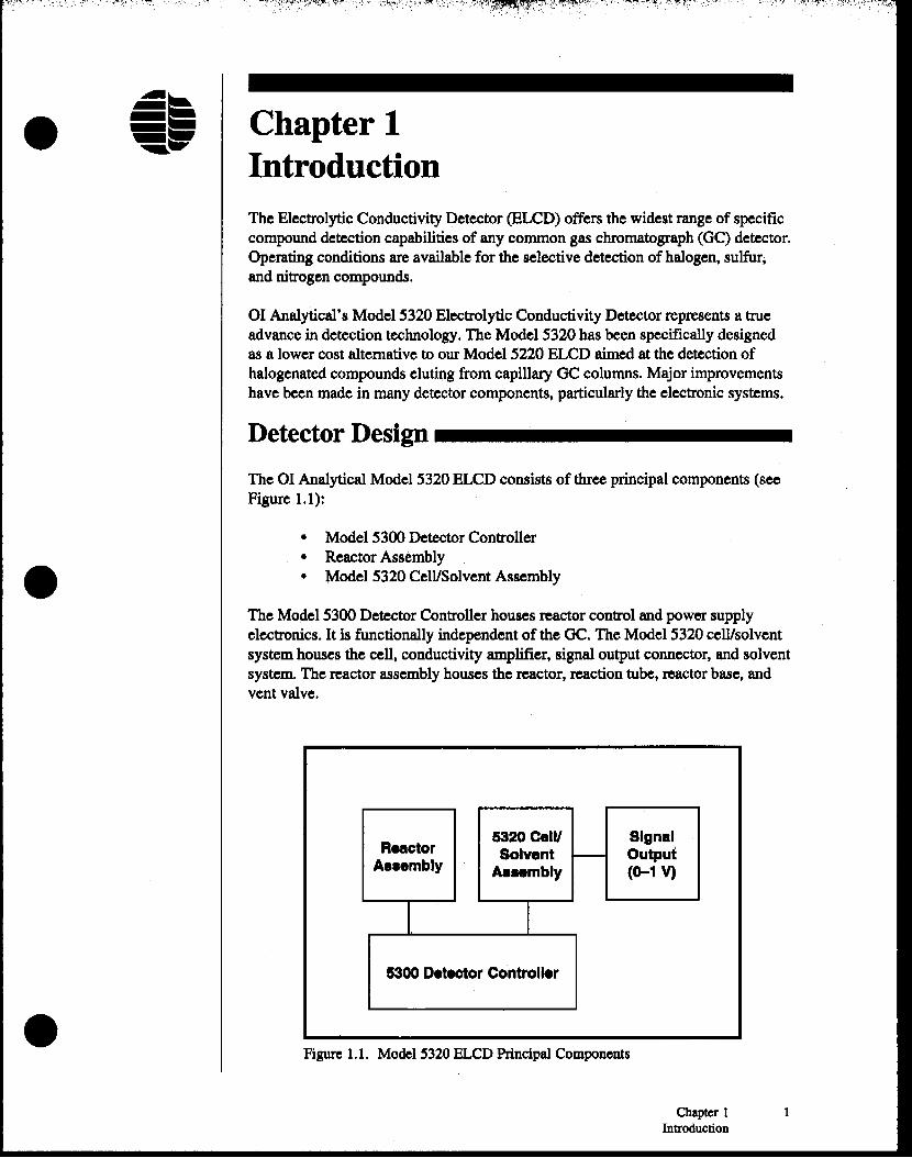
The 01 Analytical Model 5320 ELCD consists of three principal components (seeFigure 1.1):
• Model 5300 Detector Controller• Reactor Assembly• Model 5320 Cell/Solvent Assembly
The Model 5300 Detector Controller houses reactor control and power supplyelectronics. It is functionally independent of the OC. The Model 5320 cell/solventsystem houses the cell, conductivity amplifier, signal output connector, and solventsystem. The reactor assembly houses the reactor, reaction tube, reactor base, andvent valve.
Reactor6320 celli SignalSolvent ,.....- Output
A••embly AaHmbly (0-1 V)
I I5300 Detector Controller
Figure 1.1. Model 5320 BLCD Principal Components
Chapter 1Introduction
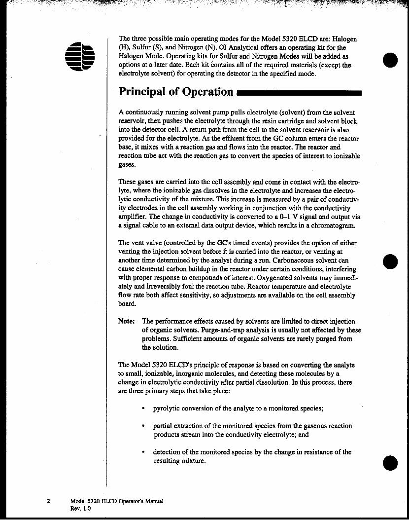
The three possible main operating modes for the Model 5320 ELCD are: Halogen(H), Sulfur (S), and Nitrogen (N). 01 Analytical offers an operating kit for theHalogen Mode. Operating kits for Sulfur and Nitrogen Modes will be added asoptions at a later date. Each kit contains all of the required materials (except theelectrolyte solvent) for operating the detector in the specified mode.
Principal of Operation _
A continuously running solvent pump pulls electrolyte (solvent) from the solventreservoir, then pushes the electrolyte through the resin cartridge and solvent blockinto the detector cell. A return path from the cell to the solvent reservoir is alsoprovided for the electrolyte. As the effluent from the GC column enters the reactorbase, it mixes with a reaction gas and flows into the reactor. The reactor andreaction tube act with the reaction gas to convert the species of interest to ionizablegases.
These gases are carried into the cell assembly and come in contact with the electrolyte, where the ionizable gas dissolves in the electrolyte and increases the electrolytic conductivity of the mixture. This increase is measured by a pair of conductivity electrodes in the cell assembly working in conjunction with the conductivityamplifier. The change in conductivity is converted to a 0-1 V signal and output viaa signal cable to an external data output device, which results in a chromatogram.
•
The vent valve (controlled by the OC's timed events) provides the option of eitherventing the injection solvent before it is carried into the reactor, or venting atanother time determined by the analyst during a run. Carbonaceous solvent can •cause elemental carbon buildup in the reactor under certain conditions, interferingwith proper response to compounds of interest. Oxygenated solvents may immedi-ately and irreversibly foul the reaction tube. Reactor temperature and electrolyteflow rate both affect sensitivity, so adjustments are available on the cell assemblyboard.
Note: The performance effects caused by solvents are limited to direct injectionof organic solvents. Purge-and-trap analysis is usually not affected by theseproblems. Sufficient amounts of organic solvents are rarely purged fromthe solution.
The Model 5320 ELCD's principle of response is based on converting the analyteto small, ionizable, inorganic molecules, and detecting these molecules by achange in electrolytic conductivity after partial dissolution. In this process, thereare three primary steps that take place:
• pyrolytic conversion of the analyte to a monitored species;
• partial extraction of the monitored species from the gaseous reactionproducts stream into the conductivity electrolyte; and
• detection of the monitored species by the change in resistanoe of theresulting mixture. •
2 Model S320 BLeD Operator's ManualRev. 1.0

•
•
•
These processes occur entirely within the reactor and cell assemblies in a continuous manner. The GC column effluent is mixed with reaction gas (H, or air)in thereactor base. The mixture then flows through a reaction tube within the reactorwhere the sample is pyrolyzed at temperatures from 700° to ll00°C. The reactionproducts are swept into the cell assembly where they are mixed with the deionizedelectrolyte, then the electrical resistance of the resulting solvent-gas mixture ismeasured.
Selectivity for a given element depends upon:
• the reaction conditions used for converting the analyte to the monitoredspecies;
• the use of chemical scrubbers for removing interferences; and
• the type and pH of the electrolytic conductivity solvent.
Specific operation details for the various operating modes are summarized in Table1.1.
Depending on the reaction gas used, conditions within the reaction tube can bereductive (H:z) or oxidative (air). The various reaction products produced in thethree primary operating modes and the basis of selectivity are summarized inTables 1.2 through 1.4.
Features _
Operating Parameters forSelective Detection
ConductivityMode Rx Temp (0C) Rx Gas Mode Solvent ScrubberHalogen(H) 900 - 1100 ~ 100% ACS Reagent None
Grade a-propanol.Sulfur (S) 800 - 1100 Air 100% ACS Reagent S~Mode
Grade methanol.Nitrogen (N) 800·1100 ~ 90:10 (vlv) 18 N~Mode
megaobmlcm orbetter deionized,degassed waterlACS reagent grade .t-butyl alcohol.
Table 1.1. Table of Operating Parameters for Selective Detection
Chapter 1 3Introduction

Main Reaction Products for X"Mode Detection(Nickel Reaction 'Iube, Reductive Conditions) •
Compound CombustionType Product{s)
Halogen HX
Sulfur H,S
Nitrogen ~
Hydrocarbon CH4
(loweralkanes)
Oxygen H2O
Selection
Selectivelydetected
Poorlyionized
Poorlyionized
Not ionized
Poorlyionized
Table 1.2. Main ReactionProducts for X-Mode Detection
Main Reaction Products for N"Mode Detection(NIckel Reaction 'Iube, Reductive Conditions)
Compound CombustionType Product(s) Selection
Nitrogen ~ Selectivelydetected
Halogen HX Removed by post-reactorscrubber
Sulfur H,S Removed by post-reactorscrubber
Hydrocarbon CH4 Not ionized(loweralkanes)
Oxygen Hp Poorlyionized
Table 1.3. Main ReactionProducts for N-Mode Detection
4 Model ~320 BLeD Operator's ManualRev. 1.0
(.
•

•
•
•
Main Reaction Products for S..Mode(Alumina Reaction Thbe, OxidatJve Conditions)
Compound CombustionType Product(s) Selection
Sulfur 502 Selectively detected
Halogen HX Removed by post-reactorscrobber
Nitrogen N2·NONot ionized
Hydrocarbon CO2Poorly ionized
(lower alkanes)
Oxygen ~O Poorly ionized
Table 1.4. Main Reaction Products for S-Mode Detection
• Low maintenance cell with quick-disconnect.attachments.
• Compact modular design.
• Directly interfaces to several OC makes and models.
• Improved design allows reaction tubes to be replaced quickly and easily.
• Direct interface to the 01 Analytical Model 4430 or Model 5230 Photoionization Detector (PID) without transfer line (using single detector port).
• Minimal operator-interface or adjustments.
• Detector base is designed for capillary columns.
• Reaction gas serves as makeup gas.
• Packed column kit is optional.
• New reactor design eliminates solid graphite ferrules, using brass andgraphite/Vespel'" (GRPNSP) ferrules,
• Reactor temperature and solvent flow are analog-controlled.
• Simplified signal processing.
• Detector base and Model 5300 Detector Controller are interchangeable with the01 Analytical Model 5360 Halogen Specific Detector (XSDj.
Chapter 1Introduction

• Control module incorporates quick-change, disposable deionizing cartridge andsimplified solvent system.
• PID can be added to form integral dual-detector.
• Vent(s) may be turned on and/or off using the GC's timed events options.
Principal Applications _
•• EPA 601• EPA 608• EPA 611• EPA 502.1• EPA S02.2• Fluorinated and Chlorinated
Contaminates in Process Streams
• Pesticides, HX, N, S
• PCBs• Pharmaceuticals• Industrial Chemicals• Nitrosamines• Forensic Science
Specifications _
Any halogen, nitrogen, or sulfur in a compound eluting from a GC column isconverted under reductive or oxidative conditions to an ionizable gas (HX, NH
3,
S02) in a high temperature catalytic micro-reactor. Gaseous reaction products arecarried into a detector cell where they are dissolved with a deionized electrolyte,which increases the electrolytic conductivity of the mixture. This instantaneouschange in conductivity is amplified, producing a signal proportional to the mass ofhalogen, nitrogen, or sulfur in the original compound. Specificity results from thechoice of electrolyte, reactor conditions, and scrubber employed.
Modes of Operation• Halogen• Sulfur• Nitrogen
Solvent Vent Valve• Controlled by GC timed events relay (24 V)
Dimensions (5300 Detector Controller)• 8.2S" H x S.OO" W x 12.0" D
Weight• Controller: 8.4 lbs
Dynamic Range• Halogen 5 x 1()lI• Nitrogen O.S x 1()6• Sulfur 1 x 1()l1
6 Model 5320 ELCD Operator's ManualRev. 1.0
i.
•

•
•
•
".'. ~.'
Selectivity _• Halogen ClIHC > 1()6
ClIN> 1(ylClIS> 1(yl
• Nitrogen NIHC> 1()6N/CI> 1()4
N/S> 1()4
• Sulfur SIHC > 1(ylS/CI> 10'SIN> 1(yl
Reactor Temperature• Range: 800° to 11OO°C (in 100°C increments)• Stability: ±1°C
Solvent Flow• Operator selectable 10-100% in 1% increments• Flow Range: 0-100 J.1l1min
Detector Output• 1 V full scale analog voltage
Gas Requirements• Halogen Mode: hydrogen, ultrahighpurity, 99.999% or better• Sulfur Mode: air, ultrahighpurity, dry, 0.1 molar ppm HC or better• NitrogenMode: hydrogen, ultrahighpurity, 99.999%or better
Power Requirements• 90-260 VAC (±10%)/47--63Hz, 200 W
Note: Performance is affectedby severalfactors, including OC, column, electrolyte, and compoundclass.
Safety Information _---------
The Model 5320 ELCD has been designedin accordance with recognized safetystandardsand for use indoors. Using the instrumentin a manner not specified bythe manufacturermay impair the instrument's safetyprotection.Whenever thesafety protectionof the Model 5320 BLCDhas been compromised, disconnect theinstrumentfrom all power sourcesand secure the instrumentagainstunintendedoperation.
Chapter 1 7Introduction
11 'j.
Operator-Precautions
For operator safety, pay attention to WARNING and CAUTION statementsthroughout the manual.
-.•
•
A WARNING indicates a condition or possible situation that could result inphysical injury to the operator.
A CAUTION indicates a condition or possible situation that could damage ordestroy the product or the operator's work.
Warnings and precautions in this manual or on the instrument must be followedduring operation, service, and repair of the instrument. Failure to follow thesewarnings and precautions violates the safety design standards and intended use ofthe instrument. 01 Analytical will not be liable for the operator's failure to complywith these warnings and precautions.
General Precautions
The Model S320 ELCD must be connected to the AC power supply mainsthrough a three-conductor power cord with the third wire firmly connected toan electrical ground at the power outlet. Any interruption of the groundingconductor or disconnection of the protective earth terminal could cause a shockresulting in personal injury.
• Disconnect the AC power cord before removing any covers. •• Replace or repair faulty or frayed insulation on power cords.
• Perform periodic leak checks on supply lines, fittings, and pneumatic plumbing.
• Arrange gas lines so that they can not become kinked, punctured, or otherwisedamaged, and will not interfere with foot traffic.
• Tum off the main power switch and disconnect the main power cord beforeusing a liquid solution to locate leaks.
• Do not restrict airflow on the back and/or bottom of the unit.
• Wear safety glasses to prevent possible eye injury.
• Do not replace blown fuses inside the detector controller. Only trained servicepersonnel should access the interior of the detector controller.
• Do not perform unauthorized modifications or substitute parts that are not 01Analytical original instrument parts. Any unauthorized modifications orsubstitutions will void the warranty.
• Verify that all heated areas have cooled before handling or wear adequate handprotection to prevent bums.
8 Model ~320 BLeD Operator'sManualRev, 1.0
•

•Compressed Gas Cylinders Precautions
• Compressed gases should be stored and handled strictly in accordance withrelevant safety codes.
• Fasten all cylinders securely to an immovable structure or permanent wall.
• Store or move cylinders only in a vertical position. Do not move or transportcylinders with regulators attached.
• Use only approved regulators and tubing connections.
• Connect cylinders to instruments with pressure ratings that are significantlygreater than the highest outlet pressure from the regulator.
Safety SYmbols
The following symbols may be located on the instrument:
See accompanying instruction for more information.
•
•
Indicates a hot surface.
Indicates hazardous voltages.
Indicates earth (ground) terminal.
Chapter 1 9Introduction
10 Model ~320 ELCD Operator's ManualRev. 1.0
Notes
•
•

•
•
•
Chapter 2Description of Components
Principal Components
Model 5300 Detector Controller provides control for the reactor temperatureand power to both the reactor and cell assembly. The Model 5300 can control oneModel 5320 ELCD or one Model S360XSD"'. Electrical components include thepower supply, reactor temperature controller, ON power and AT TEMP LEDs, andtemperature set switch.
Model 5325 CeWSolvent Assembly includes the conductivity cell, its enclosure and mounting hardware, its associated fluid-flow and electrical lines, thesolvent pump and reservoir, and the conductivity amplifier. This assembly housesthe "sensor" portion of the detector-the conductivity cell. Conversion of thesignal from the conductivity cell to a usable output occurs on the cell amplifierboard in the cell assembly. The conductivity amplifier generates a 0-1 V signal,which is output to a data handling device via a signal cable. The cell amplifierboard contains all of the devices (switches and pot adjustments) necessary to setthe detector's operating parameters (excluding temperature).
Model 5320 Reactor Assembly includes the reactor, reactor base, and ventvalve. A reaction tube is installed inside the reactor. The reactor assembly isinstalled in a GC detector port and accepts a column in its base. The OC analytesare converted to ionizable molecules inside the reaction tube.
Chapter 2 11Description of Components
, J" ::.1' .~L
Model 5300 Detector Controller -Front View _
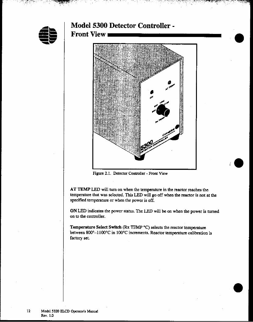
Figure 2.1. Detector Controller - Front View
AT TEMP LED will turn on when the temperature in the reactor reaches thetemperature that was selected. This LED will go off when the reactor is not at thespecified temperature or when the power is off.
ONLEDindicates the power status. The LEDwill be on when the power is turnedon to the controller.
Temperature Select Switch (Rx TEMP "C) selects the reactor temperaturebetween 800°-11OO°C in 100°Cincrements. Reactor temperature calibration isfactory set.
•
•
•12 ModelS320 ELCD Operator's Manual
Rev. 1.0

•
•
•
WARNING:This receptacle isto be used with apower cord and
power sourceeach having a
protective eartnground.
Model 5300 Detector Controller ·
Back View -------------
Signal InConnector
Signal OutConnector
Auxilary Supply
Reactor Power, Supply Connector
Power Receptacle
Figure 2.2. Detector Controller - Back View
Power Switch (rocker switch) turns the reactor power, bias voltage, electrometerpower, and cell amplifier board power on/off. Power status is indicated by the ONLED on the front of the controller.
Power Receptacle is an lEC (International Electrotechnics Convention) type
power inlet receptacle.
Reactor Power Supply Connector (3-pin Molex connector) joins the reactorpower cable to supply power to the reactor.
Signal In Connector (6-pin connector) joins with the signal probe cable in theModel 5360 XSD. This connector is not used with the Model 5320 ELCD.
Slgnal Out Connector (BNC connector) provides a signal output voltage with anominal range of 0 to 1 volt for the Model 5360 XSD. This connector is not usedwith the Model 5320 ELCD.
Chapter 2 13Description of Components
i"'·'
Cell Connector
Model 5325 Cell/Solvent Assembly ·Top View _
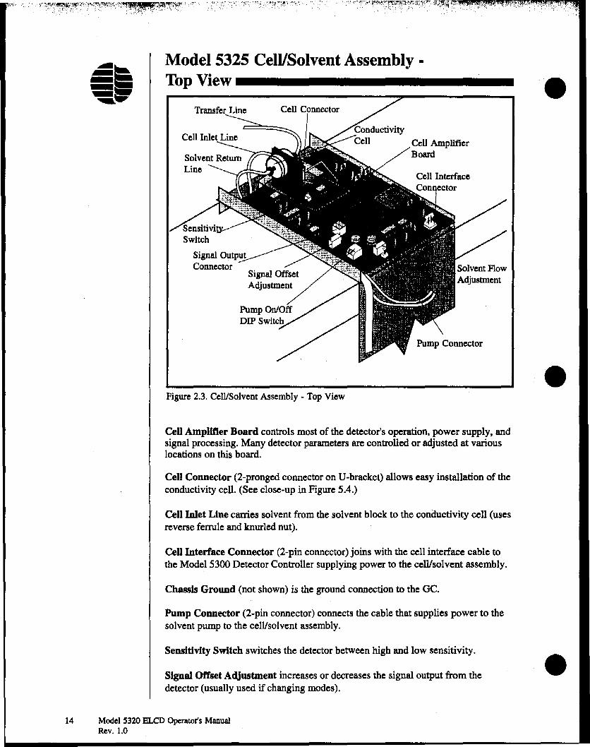
Figure 2.3. Cell/Solvent Assembly ~ Top View
Cell Ampllfter Board controls most of the detector's operation, power supply, andsignal processing. Many detector parameters are controlled or adjusted at variouslocations on this board.
Cell Connector (2-pronged connector on U-bracket) allows easy installation of theconductivity cell. (See close-up in Figure 5.4.)
Cell Inlet Line carries solvent from the solvent block to the conductivity cell (usesreverse ferrule and knurled nut).
Cell Interface Connector (2-pin connector) joins with the cell interface cable tothe Model 5300 Detector Controller supplying power to the cell/solvent assembly.
Chassis Ground (not shown) is the ground connection to the GC.
Pump Connector (2-pin connector) connects the cable that supplies power to thesolvent pump to the cell/solvent assembly.
Sensitivity Switch switches the detector between high and low sensitivity.
Signal Offset Adjustment increases or decreases the signal output from thedetector (usually used if changing modes).
14 Model S320 BLeD Operator's ManualRev. 1.0
•
•
•

•Signal Output Connector (4-pin connector) provides a signal output voltage witha nominal range of 0 to 1 volt. The detector output cable (ordered separately)provides the detector signal to an HP AlB board or other data handling device.Other cables are available when connecting to other makes or models of datahandling devices.
Solvent Flow Adjustment sets and adjusts the solvent flow going to the conductivity cell.
Solvent Return Line transfers waste solvent and gas to the solvent reservoir (usesreverse ferrule and knurled nut).
Transfer LIne transfers reaction products from the reactor to the cell (uses reverseferrule and knurled nut).
Model 5325 Cell/Solvent Assembly -
Side View -------------
• SolventReturn Line
cen InletLine
Solvent PumpInlet Line ----"'=
Figure 2.4. Cell/Solvent Assembly- Side View
Solvent FlowBlock
ResinCartridge
•
Resin Cartridge contains two lo-micron filters and ion exchange resin. It filtersthe solvent, removing ions and particulate impurities.
Solvent Bypass Line carries excess solvent from the solvent flow block to thesolvent reservoir. Only a small portion of the solvent pumped is required at thecell.
Solvent Flow Block accepts solvent from the solvent pump and resin cartridge andsplits it between the solvent bypass and cell inlet line. All connections are madewith a knurled nut and a double-sided PEEK ferrule.
Chapter 2 ISDescription of Components

Solvent Pump Inlet Line carries solvent from the solvent reservoir to the solventpump.
Solvent Pump Outlet Line carries solvent from the solvent pump to the resincartridge. •Solvent Reservoir (SOO·m.L bottle) contains the electrolyte solvent to be used. Theelectrolyte solvent must be appropriate to the mode of analysis.
Model 5320 Reactor Assembly _
•
Reactor ConductivityAssembly
ReactorReactor PoweConnector
Reactor Base Reaction Tube
Adapter~V'errule
Vent Valve" .$ /Vent ValvoPower Connector ..,; ~
~~ : ----...... 1
,~::-,4ii ~, , Vent PortDetector Base ,/~/ -00 - I' /
~/ . \>~j.o-
t~ ....,::: ",""" ~_"-cr~~/~- 4w J ' ~--
R . 0 ""-:..':;1, ,.. J ~':/-'_______
eaction as, ';;'4 /'i Vent LineInlet Tube ...",' .,,~~.
"'~'
ReactorBas~~:''" Column Ferrule
Column Nut
Column
Figure 2.S. Reactor Assembly
Reaction Gas Inlet Tube connects to a source of reaction gas (flowing at the ratespecified for the mode of operation) and allows this gas to flow into the bottom ofthe reactor through the reactor base.
Reaction Tube is inserted into the reactor and catalyzes the conversion of organicspecies to the corresponding ionizable gases. The tube used for the Halogen orNitrogen Mode operation is specially treated nickel; for the Sulfur mode, analumina tube is standard. Other materials may be used for specific applications.
Reactor heats the reaction tube to produce the conditions necessary for propersensitivity to H, N, or S compounds. It contains a removable reactor core. •
16 Model 5320 BLCD Operator's ManualRev. 1.0

•
•
•
Reactor Base provides a connection to the GC column, allows reaction gas(hydrogen Of air) to introduced, allows the vent line to connect to the vent valve,and supports the reactor. This base mounts the detector securely into the detectorport of the OC. The base is specifically designed for each particular OC model.
Reactor Conductivity Assembly (not shown) seals the reaction tube to thetransfer line that leads to the cell, by use of a ORPNSP ferrule on the reactor endand a Teflon~ (TFE) ferrule on the transfer line end. (See detail in Figure 3.2.)
Reactor Power Connector (4-pin connector) mates with the reactor power cableand makes the power connection between the Model 5300 Detector Controller andthe reactor heating filament
Solenoid Valve Cable (not shown) connects to OC timed events relays (or cable)to control vent valve functioning.
Vent Valve, when closed (de-energized), allows all reaction gas to enter thedetector base and flow through the reaction tube. When open (energized), the ventvalve allows most of the GC effluent and some reaction gas to pass through thelower vent line and out the valve, instead of through the reaction tube. It is controlled and programmed using the OC timed events control.
Vent Line connects to the vent valve so that unwanted GC effluents pass throughthe valve instead of through the reactor when the vent valve is open.
Vent Port (outlet fitting) is the exit port for the flow of reaction (and columneffluent) gas through the reactor when the vent is open.
Vent Valve Power Connector joins with the vent cable. It makes the connectionbetween the vent valve and the vent cable.
Chapter 2 17Description of Components

Notes
•
I •
18 Model ~320 ELCD Operator's ManualRev. 1.0
•
~,H" ;,' ':,,'.'
• Chapter 3InstallationIn Chapter 2 the names and functions of the various components of the ELCD weredefined. These names are used in this chapter to refer to components involved inthe installation of the detector onto a gas chromatograph.
A signal cable for connecting the signal output of the detector to a data handlingdevice is required. (Electrolyte is not supplied: electrolytes are specified in Table4.1 of Chapter 4. All alcohol used for electrolyte should be ACS Reagent Gradequality.)
Stand-Alone 5320 ELCD or 5322 Dual ELCDInstallation onto an HP 5890 _
Preparing the GC
• Turn off the OC power.
• • Remove the GC oven top. top right, right side. left side. and rear covers.
•CAUTION:
Verify that thereaction tube is
in place. Thislocation is themost common
place that a leakis found.
• Remove the selected detector port cover and insulation plug.
• Remove the insulation inside the detector port.
Installing the Reactor Base and Reactor
• Insert the detector bracket with the reactor base into the appropriate detectorport. (Do not remove the top plastic plug from the top of the reactor base untilready to install the reaction tube.)
• Align the holes of the detector base with the holes in the top of the OCt andscrew the detector base onto the OC.
• Route the reaction gas line along the top of the OC using the existing tubingguides.
• Attach the gas line from the reactor base to the port of the gas flow module onthe left side of the OC. If a gas flow module is not installed. see "Installing theGas Flow Module" in this chapter.
• Install the reaction tube and brass ferrule (part #223776) into the reactor baseby tightening the reactor base adapter (part #223743) with a 1/4" nut driver(supplied in start-up kit). See Figure 3.1. Verify that the reaction tube is fullyseated into the reactor base.
Chapter 3 19Installation

Reactor#227496
Reaction Tube*260323 (HIN Mode)
:J,- #217209 (8 Mode)
, Reactor Sue AdapterH223743
•Brass Ferrule :
#223776 ---gI
Figure 3.1. Model 5320 ELCD
• Slide the reactor over the reaction tube. •(• Tum the reactor while slightly pressing downward, to ensure proper seating ofthe reactor onto the reactor base.
• Slide and properly seat the reactor top fitting (part #227462), ORPNSP ferrule(Part #216366), and reactor union (part *234021) over the reaction tube andslightly tighten down. (see Figure 3.2).
• Attach the reactor power cable (Part #245506) to the reactor power connectoron the detector, and route the cable to the back of the OC.
• Connect the other end of the reactor power cable to the reactor power supplyconnector on the back of the Model 5300 Detector Controller.
• Plug the vent valve cable (part #214890) into the vent valve (verify that thevent is screwed down securely). Route the cable to the back of the OC and intothe right side of the GC. Attach the pins on the end of the cable into theappropriate connectors on the HP 5890 main board (back top comer).
• Remove the bottom plastic plug from the detector base.
• Open the GC oven door to install the column. Slide the column through the nut(part #223057) and the appropriate GRPNSP tube ferrule. Note the proper •orientation of the ferrule, with the tapered end toward the nut (see Figure 3.3).
20 Model !l320 ELCD Operator's ManualRev. 1.0
ORPNSP Ferrule#216366
Teflon Ferrule1:>--_- #216338
ReactorNut'226357
Reactor Union#234021:--------+:n l
ReactorTop Fitting £N227462~
I
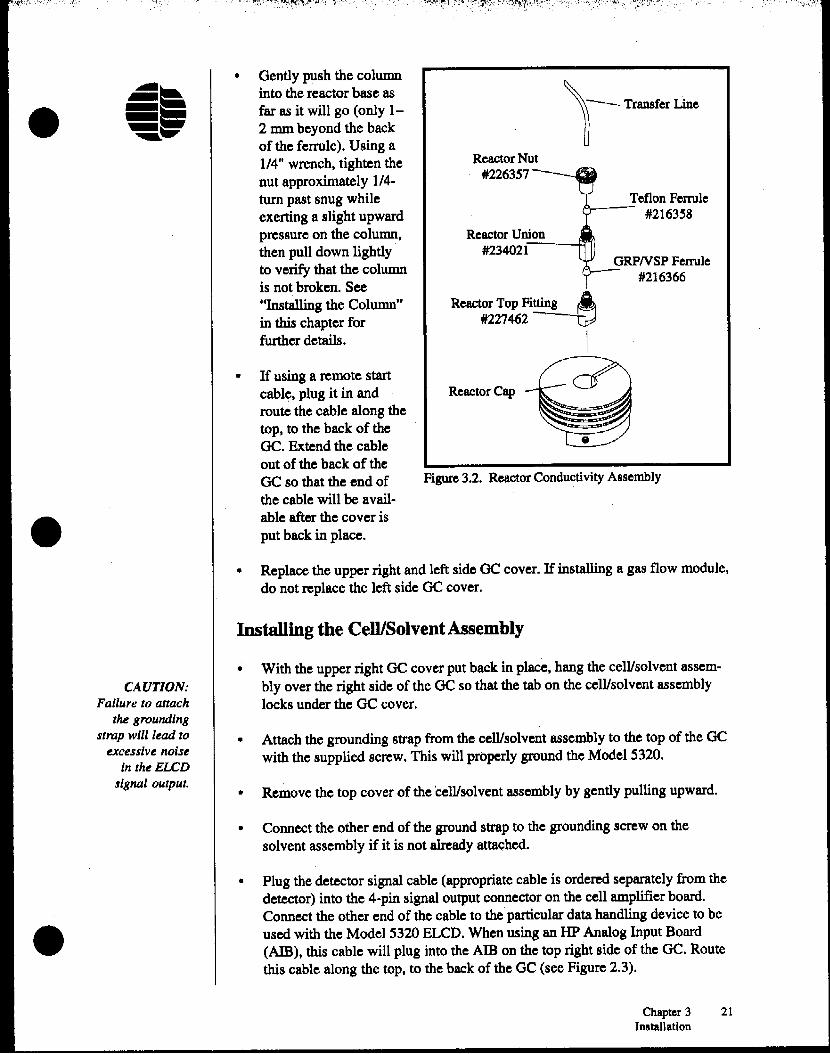
• Gently push the columninto the reactor base asfar as it will go (only 12 rom beyond the backof the ferrule). Using a1/4" wrench, tighten thenut approximately 1/4turn past snug whileexerting a slight upwardpressure on the column,then pull down lightlyto verify that the columnis not broken. See"Installing the Column"in this chapter forfurther details.
•
•
• If using a remote startcable, plug it in and RcactorCaproute the cable along thetop, to the back of theOC. Extend the cableout of the back of theGC so that the end of Figure3.2. ReactorConductivity Assembly
the cable will be avail- .able after the cover isput back in place.
• Replace the upper right and left side OC cover. If installing a gas flow module,do not replace the left side GC cover.
Installing the Cell/SolventAssembly
CAUTION:Failure to attach
the groundingstrap will lead to
excessive noisein theELCD
signal output.
•
•
•
With the upper right GC cover put back in place, hang the cell/solvent assembly over the right side of the GC so that the tab on the cell/solvent assemblylocks under the GC cover.
Attach the grounding strap from the cell/solvent assembly to the top of the OCwith the supplied screw. This will properly ground the Model 5320.
Remove the top cover of the cell/solvent assembly by gently pulling upward.
• Connect the other end of the ground strap to the grounding screw on thesolvent assembly if it is not already attached.
•• Plug the detector signal cable (appropriate cable is ordered separately from the
detector) into the 4-pin signal output connector on the cell amplifier board.Connect the other end of the cable to the particular data handling device to beused with the Model 5320 BLCD. When using an HP Analog Input Board(AlB), this cable will plug into the AlB on the top right side of the GC. Routethis cable along the top, to the back of the OC (see Figure 2.3).
Chapter 3 21Installation

': "'I ~;~lrFt~:',~:1r.~~,'I(~?:~r:"~: V~\:j; :':: :',7V1~/l~"s~r~,~~,~~:':tf,~',\~,~· '". . :~i;i ~~~,~~,!~:.;:,~.~ I
(
• Plug the cell interface cable (part #247007) to the cell interface connector on
fl the cell amplifier board (see Figure 2.3).
• Route the cell interface cable through the cable fastner and out the back of the •cell solvent assembly.
• Route the cell interface cable to the back of the GC.
• Make a transfer line by cutting a mfnfmum length of 1/16" x .20 J.D. Teflon'"tubing that will extend from the top of the reactor to the conductivity celllocated on the cell amplifier board.
• Connect one end of the transfer line to the conduotivity cell by sliding theCAUTION:
Telfon transfer line through the 1/16" male knurled nut (part #226357) andOvertighteningthe nuts onto the 1/16" Teflon ferrule (part #272443).
conductivity cellmay result in • Finger-tighten the 1/16" male knurled nut and transfer line into the conductivity
insufficient cell. Do not overtighten (see Figure SA).solventflow
through the cell. • Connect the other end of the transfer line to the top of the reactor by sliding thetubing through the 1/16" reactor nut (Part #226357) and Teflon ferrule (part#216358). Note the direction of the ferrule in Figure 3.2.
• Finger-tighten the 1/16" reactor nut and transfer line .onto the top of the reactor.
• Open the solvent enclosure by pulling outward on the side cover of the celli (.solvent assembly.
• Remove the solvent reservoir lid.
• Fill the solvent reservoir with the appropriate solvent for the application (seeTable 4.1).
• Replace the solvent reservoir lid.CAUTION: Ifapositive flow of
Installing the Columngas to theconductivity cell
is not present The Model 5320 ELCD base is optimized for 0.53 mm and smaller 1.0. capillary(l.e., when the columns. To install the column into the detector base:column is notinsttllled). the • Remove the 1/16" nut from the reactor base assembly or the start-up kit
solvent flow mustsupplied with the Model S320 BLCD.be turned off.
ThLJ will preventSlide the column nut onto the end of the capillary column.solvent from •
bacliflushing intothe reactor and • Slide a 1/16" GRPNSP ferrule onto the column (with the tapered end facing
detector base, toward the column nut) (see Figure 3.3). See Table 3.1 for the appropriateand irreversibly ferrule.
fouling the •reaction tube.
22 Model 5320 ELCD Operator's ManualRev. 1.0
"" ...•......".: ' ..",<11... ....,~ ',',"I"
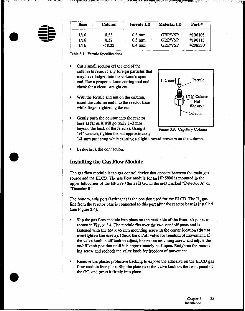
•Base
1/161/161/16
Column
0.530.32
<0.32
Ferrule I.D
0.8 m.m0.5 m.m0.4 m.m
Material I.D
ORPNSPGRPNSPORPNSP
Part #
#196105#196113#208330
Table 3.1. Ferrule Specifications
• Cut a small section off the end of thecolumnto remove any foreignparticles thatmay have lodged into the column's openend. Use a proper columncutting tool andcheck for a clean, straightcut.
1-2 mm{ ... Ferrule
'~---...
Installing the Gas Flow Module
Leak-check the connection.
1/16" ColumnNut
#2230~7
I--column
Figure 3.3. Capillary Column
With the ferrule and nut on the column,insert the column end into the reactor basewhile finger-tightening the nut.
Gentlypush the columninto the reactorbase as far as it will go (only 1-2 m.mbeyondthe back of the ferrule). Using a1/4" wrench, tighten the nut approximately1/4~turn past snug whileexertinga slight upward pressureon the column.
•
•
•
•The gas flow module is the gas controldevice that appearsbetween the main gassource and the ELeD. The gas flow modulefor an HP 5890 is mounted in theupper left comer of the HP 5890Series IT OC in the area marked"Detector A" or"DetectorB."
The bottom, side port (hydrogen) is the positionused for the ELeD. The H2 gasline from the reactor base is connected to this port after the reactor base is installed(see Figure 3.4).
• Slip the gas flow moduleinto place on the back side of the front left panel asshownin Figure 3.4.The modulefits over the two standoffposts and isfastenedwith the M4 x 45 mm mounting screw in the center location (do notovertlpten the screw). Check the on/off valve for freedomof movement Ifthe valveknob is difficult to adjust, loosen the mountingscrew and adjust theon/off knob position until it is approximately half-open. Retighten the mounting sctew and recheck the valve knob for freedomof movement.
•• Removethe plastic protective backing to expose the adhesiveon the ELeD gas
flow moduleface plate.Slip the plate over the valve knob on the front panel ofthe OC, and press it firmly into place.
Chapter 3 23Installation

• Carefully route theH2 gas line from theinstalled reactorbase toward theback of the ac,then along the leftside (using the twoclips provided), andtoward the front ofthe GC until theline reaches the slotprovided.
• Attach the gassupply lines to thesolvent flow blockby using themanifold plate(part #197772) andmanifold O-ring(Part #185116) asin Figure 3.4.
Front Left Panel of :
HP~890 ~
0nJ0ff alve
Manifold O-ring
Figure 3.4. Oas Flow Module
•
installing the Model 5300 Detector Controller
• Set the Model 5300 Detector Controller in place (preferably to the right side ofthe GC).
• Plug the power cable into the power receptacle on the back of the Model 5300Detector Controller.
• Turn the power switch off.
• Plug the power cable into a standard 110 VAC power outlet.
• Plug the cell interface cable from the cell amplifier board into the auxiliarysupply connector (labeled AUX SUPPLy) on the back of Model 5300 DetectorController.
• Plug the reactor power cable into the reactor power supply connector (labeledREACTOR POWER) on the back of the Model 5300 Detector Controller.
24 ModelS320 ELCD Operator's ManualRev. 1.0
•
•
~ '~",:',,:,\I,:-:I.,".'\"\ '1',-' ','_
•
•
•
WARNING:Flammable
hydrogen gas andalcohol vapors
will be present inthe solvent
reservoir duringoperation.
Atkquate stepsshould be taken
for their ventilation.
CAUTION:Never adjust theneedle valves to
the point ofcomplete shut-off
to avoid innerseal damage.
Chapter 4OperationThis chapter discusses the operation of the detector for analyzing samples. TheModel 5320 ELeD can be operated in the Halogen, Sulfur, or Nitrogen Mode.
Setting the Gas Flows ------
Gas flows are set by adjusting the needle valve at the center of the larger on/offvalve located on the gas flow module. Use a small screwdriver to adjust the needlevalves; the valves open counterclockwise.
To adjust the gas flows, follow these procedures:
• Verify that the solvent flow is off.
• . Remove the solvent return line from the solvent reservoir and attach a flowmeter to its end.
• Verify that the vent valve is closed.
• Set the column carrier gas flow to the desired rate.
• Open the reaction gas on/off valve at the gas flow module.
• For ELCD stand-alone operation, adjust the inner needle valve until the carrierplus-hydrogen reaction gas flow equals 130 lIl1!min.
• For tandem PIDIELCD operation, open the makeup on/off valve at the gasflow module. Adjust the inner needle valve until the makeup gas flow equals10-15 mUmin. Open the sweep gas on/off valve and adjust the lamp sweepgas flow until the column-plus-makeup-plus-sweep gas flow equals 145 (±5)mUmin.
Note: In tandem operation, the PID lamp sweep gas serves as the ELCD hydrogen reaction gas.
• Remove the flowmeter from the solvent return line and insert the line into thesolvent reservoir as far as it will go.
• Leak-check the connections; do not use any liquid leak detectors around thereactor assembly and the cell.
Note: The vent valve flow is set at a fixed rate, thus requiring no adjustment
Chapter4 2~
Operation

Filling the Solvent Reservoir _
The electrolyte in the solvent reservoir will slowly evaporate and must be refilledaccordingly. Top-off the reservoir with solvent every 300 hours. Check the reservoir at least on a weekly basis.
'.Mode
HalogenNitrogen
Sulfur
Solvent (Electrolyte)
100% ACS Reagent Grade n-propanol (normal propyl alcohol)90:10 (v/v) 18 megohm-em or better deionized, degassedwater/ACS Reagent Grade t-butyl alcohol100% ACS Reagent Grade methanol
Table 4.1. BLCD Electrolyte Solvent
Note: If the solvent reservoir empties completely, the solvent pump will ron dry,accelerating wear of the internal gears in the pump head. Extended "dry"operation produces graphite gear particles at the pump outlet and causesthe solvent pump to be unable to generate and maintain sufficient pressurefor proper electrolyte flow.
Fill the electrolyte solvent reservoir with the appropriate solvent for the selectedmode, as listed in Table 4.1. The solvent reservoir holds SOO mL of electrolyte.Refill the reservoir routinely (see Chapter S, "Maintenance").
Setting the Solvent Flow _
Set the solvent flow according to the following procedure:
• Remove the solvent return line from the solvent reservoir, and insert the endinto a small vial or container suitable for collecting solvent
• Tum the solvent pump on using the pump on/off DIP switches located on thecell amplifier board (see Figure 2.3) Pushing the DIP switches up turns thepump on.
(.
26 Model 5320 ELCD Operator's ManualRev. 1.0
WARNING:Flammable
hydrogen gasand alcohol
vapors will bepresent in the
solvent reservoirduring operation.
Adequate stepsshould be taken
for their ventilation.
Note: If the solvent pump has been sitting idle for an extended. period of time,prime the pump by setting the flow to a maximum setting. If the pumpfails to prime, removing the exit line or pull the pump off the solventassembly and invert the orientation of the pump.
• Allow the pump to stabilize for S-IO minutes.
• Collect solvent in the small vial or container for 3-S minutes.
• Measure the solvent by using a microliter syringe and determine the microliterper minute rate.
• Adjust the solvent flow until the flow rate is within the range given in Table4.2. •
",,,,"
•
•
•
CAUTION: Donot condition a
new columnwhile it is
attached to thedetector base.
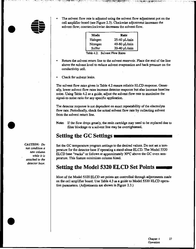
• The solvent flow rate is adjusted using the solvent flow adjustment pot on thecell amplifier board (see Figure 2.3). Clockwise adjustment increases thesolvent flow; counterclockwise decreases the solvent flow.
Mode RateHalogen 25-40 J1llminNitrogen 40-80 J1llmin
Sulfur 20-40 J1llminTable 4.2. Solvent FlowRates
• Return the solvent return line to the solvent reservoir. Place the end of the lineabove the solvent level to reduce solvent evaporation and back pressure on theconductivity cell.
• Check for solvent leaks.
The solvent flow rates given in Table 4.2 ensure reliable ELCD response. Generally, lower solvent flow rates increase detector response but also increase baselinenoise. Using Table 4.2 as a guide, adjust the solvent flow rate to maximize thesignal-to-noise ratio for any specific application.
The detector response is not dependent on exact repeatability of the electrolyteflow rate. Periodically, check the actual solvent flow rate by collecting solventfrom the solvent return line.
Note: If the flow drops greatly, the resin cartridge may need to be replaced due tofilter blockage or a solvent line may be overtightened.
Setting the GC Settings _
Set the GC temperature program settings to the desired values. Do not set a temperature for the detector base if operating a stand-alone ELCD. The Model 5320ELCD base "tracks" or follows at approximately 30°C above the OC oven temperature. This feature minimizes column bleed.
Setting the Model 5320 ELCD Set Points __
Most of the Model 5320 ELCD set points are controlled through adjustments madeon the cell amplifier board. Use Table 4.3 as a guide to Model 5320 ELeD operation parameters. (Adjustments are shown in Figure 2.3.)
Chapter 4 27Operation

I.': '.'\' ,.",·:'-t~~q~Lt~I'.~~fjJL~~i:~~·:f~%\lnt~~:r~rl"',:,I,~<,:.I.~~!:fl~:'I.'I:~:'~~~l~,~,,;,. :,.,,. .... '"'.'''
:1 Control
Sensitivity SwitchSignal (Zero) Offset
Reactor Temperature
Rx Temperature RangeHalogen Mode
Sulfur ModeNitrogen ModeVent ValveSolvent On/OffSolvent Flow
Adjustment Location/Setting
Set switch to appropriate sensitivityDetermined by background noise and offset (potadjustment on cell amplifier board)Set by front panel switch on Model 5300Detector ControllerSooo-l100DC
9000-1000°C Volatile Organics9000-11 OODC Pesticides900D-1100°C PCBsSOOD-11OO°C Semi-VolatilesSOOD-l100DC
Sooo-l100DC
Controlled by GC timed eventsOn/Off DIP switch on cell amplifier boardPot adjustment on cell amplifier board
'.
Table 4.3. Model 5320 Operation Parameters
Use the signal offset adjustment to adjust (increase or decrease) the signal outputlevel on the Model 5320 ELeD. Adjusting this pot clockwise increases the signaloffset; counterclockwise decreases the signal offset.
The sensitivity switch can be set to In for pesticides analysis or LO for purge-and- •trap analysis.
Operational Guidelines _
• Do not use Nz as carrier or makeup gas.
• Perform periodic maintenance (see Chapter 5, "Maintenance").
• Always use the vent valve to vent the solvent. Solvent injected without ventingmay immediately and irreversibly foul the reaction tube, causing severe peaktailing and loss of response.
• Do not use solvents that contain halogens, sulfur, or nitrogen. Ifpossible, alsoavoid solvents that contain oxygen.
• The Model 5320 ELeD has been designed to be left on during standby periods.Repeatedly turning the power off and on to conserve gas will increase warm-uptime and possibly foul the reaction tube or cause reactor failure.
•28 ModelS32Q BLeD Operator's Manual
Rev. 1.0

•
•
•
• Use the highest purity gases available (99.999%) for the best signal-to-noiseratio. Proper gas purity and conditioning is crucial for successful ELCDoperation.
• Replace the reaction tube, resin, and solvent lines when switching operatingmodes.
• If the resin is replaced, remove all solvent from the reservoir and refill it withnew solvent.
Model 5300 Detector ControllerOperation _
The Model 5300 Detector Controller can control one Model 5320 BleD.
• Set the temperature adjust switch to the appropriate temperature set point forthe particular application to be run.
• Turn on the power to the Model 5300 Detector Controller. The ON (power)LED on the front of the Model 5300 Detector Controller will illuminate. Oncethe reactor reaches the set operational temperature, the AT TEMP LBD willilluminate.
Chapter 4 29Operation
Notes
•
: •
•30 Model S320ELCD Operator's Manual
Rev. 1.0

• Chapter 5MaintenanceChapter 5 describes the scheduled and nonroutine maintenance of the detector.
Scheduled Maintenance _
For the most reliable performance of the Model 5320 BLCD and as a condition ofthe warranty, the following schedule of routine maintenance should be followed(see Table 5.1). Scheduled hours refer to number of hours of operation.
An instrument log book to record instrument operation time and document periodicmaintenance is recommended. This log book can be used to record results ofinspections and component replacement necessary for proper maintenance of theinstrument.
Table 5.1. Routine Maintenance Schedule•
WARNING:All servicing must
be performed byqualified service
personnel. Maintenance Item
Solvent Reservoir RefillingResin Cartridge ReplacementTransfer Line Rinsing
Schedule
300 hours700 hours
daily
ReftlllngSolvent
Note: If the solvent reservoir empties completely, the solvent pump will run dry,accelerating wear of the internal gears in the pump head. Extended "dry"operation produces graphite gear particles at the pump outlet and causesthe solvent pump to be unable to generate and maintain sufficient pressurefor proper electrolyte flow.
The electrolyte in the solvent reservoir will slowly evaporate and must be refilledaccordingly. Top-off the reservoir with one of the following solvents every 300hours (see Table 5.2). Check the reservoir at least on a weekly basis.
Mode Solvent (Electrolyte)
•Halogen 100% ACS Reagent Grade n-propanol (normal
propyl alcohol)Nitrogen 90:10 (v/v) 18 megohm-em or better deionized,
degassed water/ACS Reagent Grade t-butylalcohol
Sulfur 100% ACS Reagent Grade methanol
Table 5.2. ELCD Electrolyte Solvent
Chapter ~ 31Maintenance

Replacing Resin Cartridge
The resin cartridge performs the ion removal from the electrolyte and traps anyparticles produced from the solvent pump. Replace the resin cartridge every 700hours (approximately 1 month) according to the following procedure: •• Tum the solvent flow off.
• Remove the resin cartridge from the holder by pushing down on the resincartridge to release the resin plunger.
• Insert a new resin cartridge with the arrow pointing upward. Note the expira-tion date on the resin cartridge.
• Remove the solvent return and bypass lines from the solvent reservoir.
• Dispose of any solvent remaining in the solvent reservoir. The solvent must bereplaced when changing the resin cartridge
• Refill the solvent reservoir with new solvent. Refer to "Filling Solvent Reser-r
voir" in this chapter, for proper solvent selection.
• Adjust the solvent flow adjustment on the cell amplifier board and allow SO-100 mL of solvent to flow through the system while draining both the solventreturn and bypass lines to waste.
Replace the solvent return and bypass lines to the solvent reservoir. I ••
• Reset the solvent flow to the desired level.
• Check for solvent leaks around the ends of the resin cartridge. If necessary,adjust the resin cartridge.
Transfer Line Rinsing
The transfer line can become contaminated with decomposition products that exitthe reactor (usually unreacted hydrocarbons). The result can be peak tailing,baseline noise, and/or reduced response. Every 700 hours (approximately 1 month)or as these symptoms appear, rinse the transfer line as described in the followingprocedure.
Note: The reactor should remain hot while this procedure is performed.
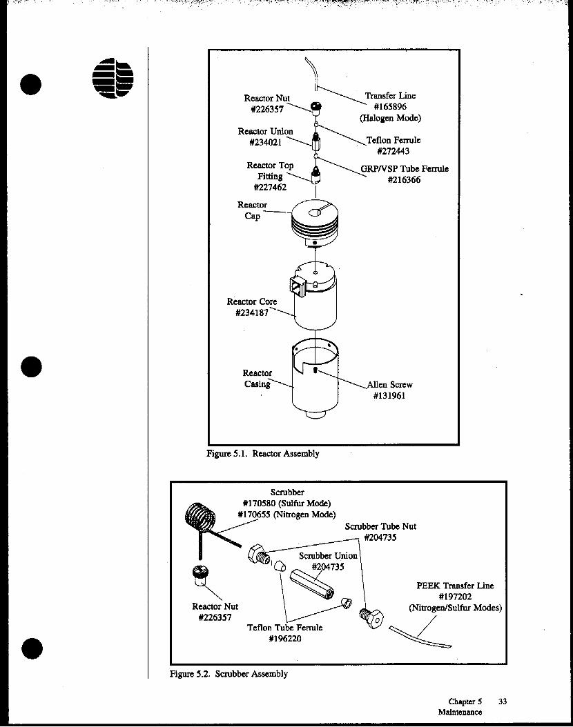
• For the Halogen Mode, unscrew the knurled reactor nut (part H2263S7) at thetop of the reactor (see Figure 5.1).
• For the Nitrogen/Sulfur Modes, disconnect the PEEK tubing (part #197202) atthe scrubber union (part #204735) by loosening the scrubber tube nut (part#204735) (see Figure 5.2). •
32 Model 5320 BLeD Operator's ManualRev. 1.0
• Reactor Nut*226357
Reactor Union*234021
Reactor TopFitting
#227462
Teflon Ferrule*272443
ORPNSP Tube Ferrule#216366
•
ReactorCap---I
Reactor Core#234187
ReactorCasing Allen Screw
#131961
Figure 5.1. Reactor Assembly
PEEK Transfer Line#197202
(Nitrogen/Sulfur Modes)
<«.
Scrubber Tube Nut#204735
~1Q,~3'
Teflon Tube Ferrule1196220
Scrubber*170580 (Sulfur Mode)
*170655 (Nitrogen Mode)
Reactor Nut*226357
• Figure ~.2. Scrubber Assembly
Chapter 5 33Maintenance
CAUTION:'I'M reaction
tube. reactor.and supportingfittings may be
hot.
• With the solvent flow on, allow the transfer line to sag to an open area on thetop of the OC, away from the reactor. Let solvent from the solvent reservoirbackflush the line onto a paper towel (it takes a few seconds for the solvent toreach the end of the line). The solvent flow can be increased to facilitate thisprocess.
• After several drops (approximately 10-20 JJL) flow from the transfer line, turnthe solvent flow off and mise the end of the line above the conductivity cell,allowing the excess solvent to flow back into the conductivity cell.
• Examine the end of the transfer line for restrictions or deformations caused byan overtightened nut. If necessary. trim the end of the line ensuring a clean.straight cut. Examine the Teflon ferrule used to seal the transfer line. Replaceif necessary. Use the Teflon ferrule (part #272443) for Halogen Mode or theTeflon tube ferrule (part #196220) for Nitrogen and Sulfur Modes.
• Reconnect the transfer line to the top of the reactor (Halogen Mode) or thescrubber union (Nitrogen/Sulfur Mode) and turn the solvent flow on. Do notovertighten the nut-flnger-tlght will suffice.
If no improvement is observed. the transfer line should be replaced. Replace theHalogen Mode transfer line with approximately 10 inches or less of 1/16" x 0.020"LD. Teflon tubing (part #165896). Replace the Nitrogen or Sulfur Mode transferline with approximately 4 inches or less of 1/16" x 0.030" I.D. PEEK tubing (part#197202).
Nonscheduled Maintenance _
Replacing Reaction Tube
To replace the reaction tube, follow the steps listed below:
• Tum off the power supply to the Model 5300 Detector Controller.
• Allow the reactor to cool to the point where it can be safely touched.
• Tum off the solvent flow using the DIP switch on the cell amplifier board.
• Tum off the reactor gas supply.
• Disconnect the transfer line by removing the knurled reactor nut (Part#272443) (Halogen Mode) or the scrubber tube nut (part #196220) (Nitrogen/Sulfur Modes) at the scrubber union (see Figures 5.1 and 5.2).
Note: A transfer line backflush can also be performed at this time. Refer to''Transfer Line Rinsing. .. in this chapter.
•
• Remove the scrubber by removing the reactor nut (part *226357) (Nitrogen/ •Sulfur Modes).
34 Model ~320ELCD Operator's ManualRev. 1.0
1/16" Tube FerruleI
1/16"Nut~#223057 Capillary
Column
Reactor Base
Vent Valve*252221
eactor
Reaction Tube*260323 (HalogenINitrogen)
*217208 (Sulfur)
Detector Bracket
Reactor Base Adapter
#223743~
1/16" Ferrule I#223776 (HalogenINitrogen) ----.;
*216366 (Sulfur) """I
•
•
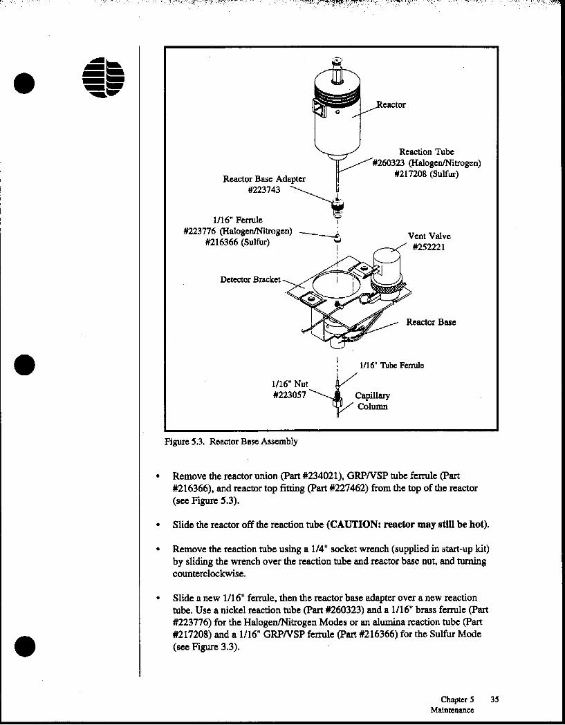
Figure 5.3. Reactor Base Assembly
• Remove the reactor union (part #234021), ORPNSP tube ferrule (part#216366), and reactor top fitting (part #227462) from the top of the reactor(see Figure S.3).
• Slide the reactor off the reaction tube (CAUTION: reactor may st1llbe hot).
• Remove the reaction tube using a 1/4" socket wrench (supplied in start-up kit)by sliding the wrench over the reaction tube and reactor base nut, and turningcounterclockwise.
•• Slide a new 1/16" ferrule, then the reactor base adapter over a new reaction
tube. Use a nickel reaction tube (part #260323) and a 1/16" brass ferrule (part#223776) for the HalogenlNitrogen Modes or an alumina reaction tube (part#217208) and a 1/16" GRPNSP ferrule (part *216366) for the Sulfur Mode(see Figure 3.3).
Chapter 5 35Maintenance

36 Model S320 BLeD Operator's ManualRev. 1.0

r:" '," I',"."'·,1I,.';":lt,J"~",
I
•
•
•
Maintaining the Transfer Line
The transfer line between the reactor and the cell assembly can become contaminated with use, resulting in peak tailing, loss of response, and/or baseline noise. Inmost instances this contamination can be removed by rinsing the line with solvent(see ''Transfer Line Rinsing" in this chapter). If no improvement is observed, thetransfer line should be replaced. Replace the Halogen Mode transfer line withapproximately 10 inches of 1/16" x 0.020" 1.0. Teflon tubing (part #165896).Replace the Nitrogen or Sulfur Mode transfer line with approximately 4 inches of1/16" x 0.030" LD. PEEK tubing (part #197202).
Replacing Scrubber
Periodic replacement of the chemical scrubber is required to maintain properELCD selectivity (for Nitrogen and Sulfur Modes, see Figure 5.2). Commonsymptoms that indicate the need to replace the scrubber include: response tohalogens, no response, low response, or blocked scrubber. Replace the scrubber asdescribed in the following procedure.
Note: Do not install the scrubber until after the reacter tube has been conditionedfor 30 minutes.
Note: The reactor should remain hot while this procedure is performed.
• Turn the solvent flow off.
• Turn the Model 5300 Detector Controller power off.
• Remove the scrubber union from the scrubber by loosening the scrubber tubenut between the scrubber and the union (see Figure 5.2). Inspect the Teflontube ferrule (Part #196220) and replace, if necessary.
• Remove the scrubber by removing the knurled reactor nut at the top of thereactor. Examine the 1/16" Teflon ferrule (part #272443) seated in the reactornut and replace, if necessary.
• Install a new scrubber by inserting the knurled reactor nut and Teflon ferruleonto the scrubber and ftnaer-tlptenlng the reactor nut onto the reactor union.See Figure 5.2 for proper scrubber orientation. Use a nitrogen scrubber (part#170655) or a sulfur scrubber (part '170580).
• Reinstall the scrubber union with the attached transfer line to the scrubber. Allfittings should be ftnaer-tlpt
• Check for leaks, but do not use any liquid leak detectors around the reactorassembly.
Chapter 5 37Maintenance
Solvent ReturnLine
Cell Bracket
TransferLine
1116" Nut
ConductivityCell
Cell Stand-offElectrode Posts
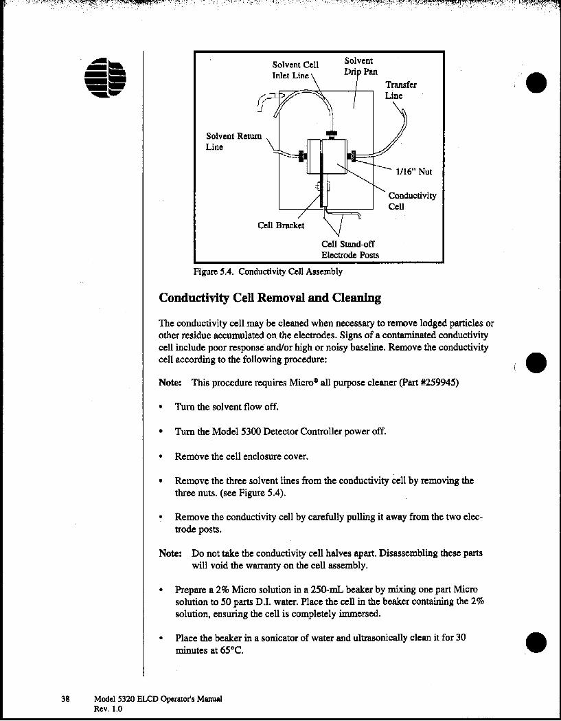
Figure SA. Conductivity Cell Assembly
Conductivity Cell Removal and Cleaning
The conductivity cell may be cleaned when necessary to remove lodged particles orother residue accumulated on the electrodes. Signs of a contaminated conductivitycell include poor response and/or high or noisy baseline. Remove the conductivitycell according to the following procedure:
Note: This procedure requires Micro~ all purpose cleaner (part #259945)
• Tum the solvent flow off.
• Tum the Model 5300 Detector Controller power off.
• Remove the cell enclosure cover.
• Remove the three solvent lines from the conductivity cell by removing thethree nuts. (see Figure 5.4).
• Remove the conductivity cell by carefully pulling it away from the two electrode posts.
Note: Do not take the conductivity cell halves apart. Disassembling these partswill void the warranty on the cell assembly.
• Prepare a 2% Micro solution in a 25Q..mL beaker by mixing one part Microsolution to 50 parts DJ. water. Place the cell in the beaker containing the 2%solution. ensuring the cell is completely immersed.
• Place the beaker in a sonicator of water and ultrasonically clean it for 30minutes at 65°C.
38 Model5320 ELCD Operator'sManualRev. 1.0
I.
••

•
•
• Remove the conductivity cell and rinse thoroughly with DJ. water. This is bestperformed using a squirt bottle and flowing the DJ. water into the three portsof the conductivity cell. Rinse one final time with methanol.
• Ifpossible, blow dry the conductivity cell with a clean gas supply. Completethe drying process by heating the conductivity cell in the GC oven for at least30 minutes at 75°C.
Note: A conductivity cell that is not completely dry will cause a high baseline.
• Reinstall the conductivity cell by carefully inserting the two electrode postsinto the conductivity cell.
• Connect the three solvent lines to the conductivity cell (see Figure 5.4). Do notovertighten the 1/16" nuts-flnaer-tlaht will suffice.
• Check the gas flow rates (see Chapter 4, "Setting the Gas Flows").
• Adjust the solvent flow to the desired flow rate and check for solvent leaks atthe conductivity cell. If leaks occur, check the thumb nuts for proper tightness,but do not overtighten. If a leak occurs at a properly tightened nut, replace theTeflon ferrule (part #272446) seated in the nut.
• Replace the cell enclosure cover.
Replacing the Reactor BaseAdapter
If the reactor base adapter (part #223743) becomes chipped, cracked, and/ordeformed, it must be replaced according to the following procedure:
• Tum the solvent pump and the Model 5300 Detector Controller power off.CAUTION:
The nut is hot! • Remove the reactor (see "Replacing Reaction Tube" in this chapter).
•
• For tandem PIDIELCD, remove the reactor base adapter from the PID outletusing either the 1/4" nut driver supplied in the start-up kit or a 1/4" open-endedwrench. Replace with a new reactor base adapter.
• For stand-alone ELCD. unscrew the reactor base adapter and pull upward.
• Install a new reactor base adapter onto the reactor base.
• Reinstall the reactor with a new reaction tube (see ''Replacing Reaction Tube"in this chapter).
• Tum the Model 5300 Detector Controller power on.
Chapter 5 39Maintenance

40 Model ~320 BLeD Operator's ManualRev. 1.0
Notes
•
; •
•
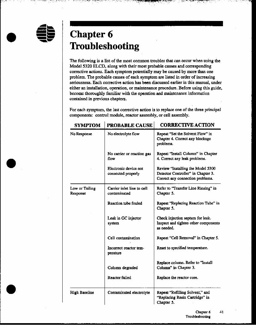
• Chapter 6TroubleshootingThe following is a list of the most common troubles that can occur when using theModel 5320 ELeD, along with their most probable causes and correspondingcorrective actions. Each symptom potentially may be caused by more than oneproblem. The probable causes of each symptom are listed in order of increasingseriousness. Each corrective action has been discussed earlier in this manual, undereither an installation, operation, or maintenance procedure. Before using this guide,become thoroughly familiar with the operation and maintenance informationcontained in previous chapters.
For each symptom, the last corrective action is to replace one of the three principalcomponents: control module, reactor assembly, or cell assembly.
SYMPTOM PROBABLE CAUSE CORRECTIVE ACTION
No Response No electrolyte flow Repeat "Set the Solvent Flow"inChapter 4. Correct any blockageproblems.
No carrier or reaction gas Repeat "Install Column" in Chapter
• flow 4. Correct any leak problems.
Electronic device not Review "Installing the Model 5300connected properly Detector Controller" in Chapter 3.
Correct any connection problems.
Low or Tailing Carrier inlet line to cell Refer to "Transfer Line Rinsing" inResponse contaminated Chapter S.
Reaction tube fouled" Repeat "Replacing Reaction Tube" inChapter 3.
Leak in GC injector Check iqjection septum for leak.system Inspect and tighten other components
as needed.
Cell contamination Repeat "Cell Removal" in Chapter S.
Incorrect reactor tem- Reset to specified temperature.perature
Replace column. Refer to "InstallColumn degraded Column" in Chapter 3.
Reactor failed Replace the reactor core.
• High Baseline Contaminated electrolyte Repeat "Refilling Solvent," and''Replacing Rosin Cartridge" inChapter 3.
Chapter 6 41Troubleshooting
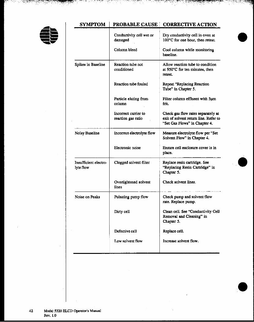
SYMPTOM PROBABLE~AUSE CORRECTIVE ACTION
Conductivity cell wet or Dry conductivity cell in oven atdamaged 100°C for ODe hour, then retest.
Column bleed Cool column while monitoringbaseline.
Spikes in Baseline Reaction tube not Allow reaction tube to conditionconditioned at 9~O°C for ten minutes, then
retest.
Reaction tube fouled Repeat "Replacing ReactionTube" in Chapter ~.
Particle eluting from Filter column effluent with SfJIDcolumn frit.
IncOII'OCt carrier to Check gas flow rates separately atreaction gas ratio exit of solvent return line. Refer to
. "Set Gas Flows" in Chapter 4.
Noisy Baseline Incorrect electrolyte flow Measure electrolyte flow per "SetSolvent Flow" in Chapter 4.
Electronic noise Ensure cell enclosure cover is inplace.
Insufficient electro- Clogged solvent filter Replace resin cartridge. Seelyteflow "Replacing Resin Cartridge" in
Chapter s,
Overtightened solvent Check solvent lines.lines
Noise on Peaks Pulsating pump flow Check pump and solvent flowrate, Replace pump.
Dirty cell Clean cell. See ''Conductivity CellRemoval and Cleaning" inChapter s.
Defective cell Replace cell.
Low solvent flow Increase solvent flow.
•
•
•42 Model S320 BLeD Operator's Manual
Rev. 1.0
.' I': '., .. ..., ~:,,', .f\':.". ~'~ T·j". ....
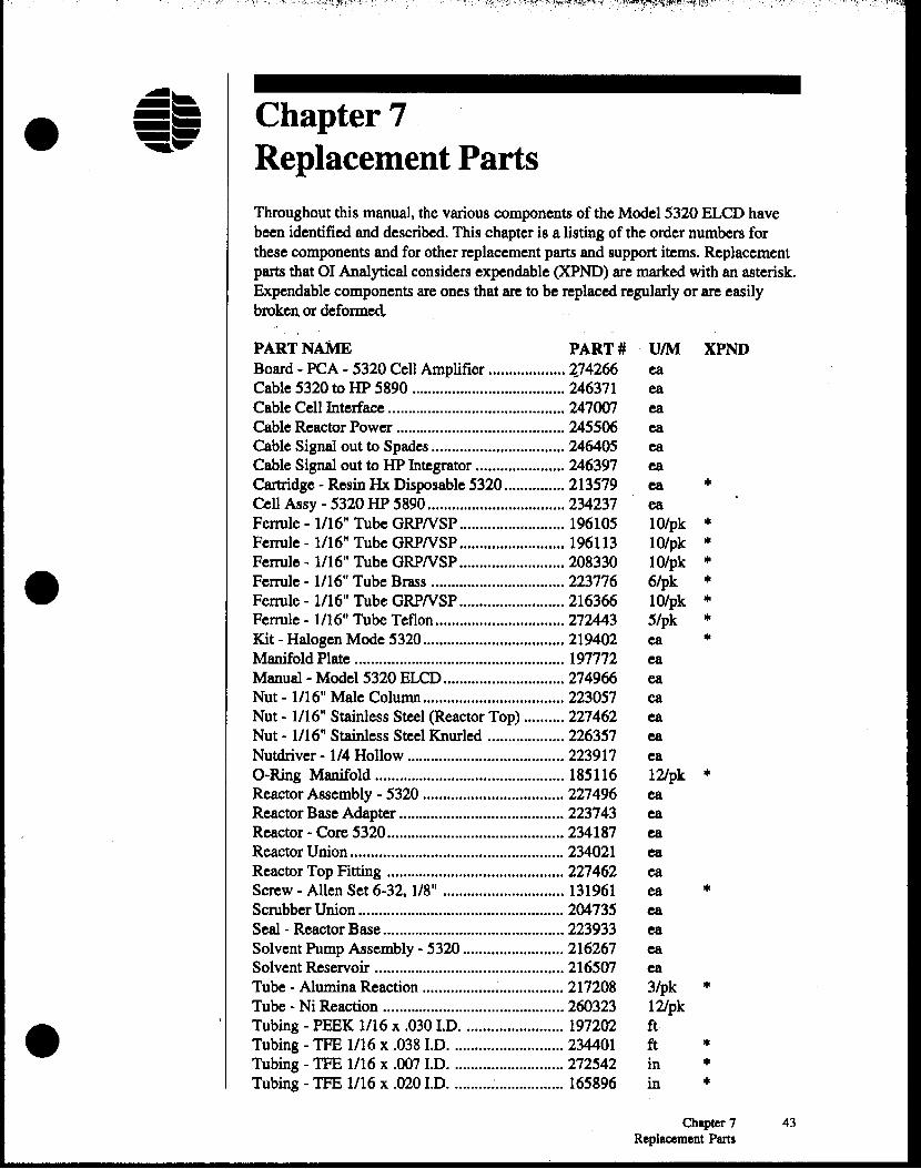
• Chapter 7Replacement PartsThroughout this manual. the variouscomponents of the Mode15320ELCD havebeen identifiedand described. This chapter is a listing of the order numbersforthese components and for other replacement parts and supportitems. Replacementparts that 01 Analyticalconsiders expendable(xpND) are marked with an asterisk.Expendable components are ones that are to be replacedregularlyor are easilybrokenor deformed
•
•
PART NAME PART #Board - PeA - 5320 CellAmplifier ~74266
Cable 5320 to HP 5890 246371Cable Cell Interface 247007Cable ReactorPower 245506Cable Signal out to Spades 246405Cable Signal out to HP Integrator 246397Cartridge- Resin Hx Disposable 5320 213579Cell Assy - 5320 HP 5890 234237Fenule - 1/16"Tube GRPNSP 196105Ferrule - 1/16"Tube ORPNSP 196113Ferrule - 1/16"Tube ORPNSP 208330Ferrule - 1/16"Tube Brass 223776Ferrule - 1/16"Tube GRPNSP 216366Ferrule- 1/16"Tube Teflon 272443Kit - HalogenMode 5320 219402ManifoldPlate 197772Manual - Model 5320 ELCD 274966Nut - 1/16"Male Column 223057Nut· 1/16" Stainless Steel(ReactorTop) 227462Nut - 1/16"Stainless SteelKnurled 226357Nutdriver• 1/4 Hollow 223917O-Ring Manifold 185116ReactorAssembly- 5320 227496ReactorBase Adapter 223743Reactor - Core 5320 234187ReactorUnion 234021ReactorTop Fitting 227462Screw - Allen Set 6-32. 1/8" 131961ScrubberUnion 204735Seal - ReactorBase 223933SolventPump Assembly- 5320 216267SolventReservoir 216507Tube - AluminaReaction : 217208Tube - Ni Reaction 260323Tubing - PEEK 1/16 x .030J.D 197202Tubing - TFE 1/16 x .038J.D 234401Tubing - TFE 1/16 x .007 J.D 272542Tubing - TFE 1/16 x .020J.D : 165896
UIM XPNDeaeaeaeaeaeaea III
ea10/pk III
lO/pk III
lO/pk III
6/pk III
10/pk III
5/pk III
ea III
eaeaeaeaeaea121pk III
eaeaeaeaeaea III
eaeaeaea3/pk III
121pkftft III
in III
in III
Chapter 7 43Replacement Parts
44 Model S320 ELCD Operator's ManualRev. 1.0
Notes
•
•
•

'.-') "'":""~ '" '.
•
•
•
IndexAApplications, Principal 6
AtTemp 12
BBoard, Cell Amplifier 14
CCables
Solenoid Valve 17Cell
Amplifier Board 14Inlet Line 14Interface Connector 14
Cell/Solvent Assembly 14-16Installation of 21-22
Chassis Ground 14Column, Installation of 22-23Components 1, 11Compressed Gas Cylinders Precautions 9Conductivity Cell 14
Removal and Cleaning 38-39Connector,
Cell 14Cell Interface 14Pump 14Reactor Power 17Reactor Power Supply 13Signal In 13Signal Out 13Signal Output 1SVent Valve Power 17
DDetector
Design 1Output 7
Detector Controller 12-13Installation 24Operation 29
Dimensions 6Dynamic Range 6
Index 4~

FFeatures 3--6Filling the Solvent Reservoir 26Flow Range 7Flow, Solvent 7
Setting 26-29
GGas Requirements 7Gas Flow Module, Installation 'of 23-24Gas Flows, Setting 25GC, Preparing 19OC Settings 27Ground 14Guidelines, Operational 28-29
HHP 5890, Preparing 19
IInstallation 19-24
LLine,
Solvent Bypass 15Solvent Pump Inlet 16Solvent Pump Outlet 16Solvent Return 15Transfer 15
Rinsing 32-34Vent 17
MMaintenance 31-39Modes of Operation 6
oON 12Output, Detector 7Operation 25-29
Principle of 2Operational Guidelines 28-29Operator Precautions 8
pPower
Receptacle 13Requirements 7Switch 13
•
•
•46 Model 5320 ffi..CO Operator's Manual
Rev. 1.0
.:- Precautions 8-9Principal Applications 6
• ~!'Principal Components 11Principle of Operation 2 '1Pump Connector 14
RReaction Gas Inlet Tube 16Reaction Tube 16
Replacing 34-36Reactor 16
Assembly 16Base 17
Installation of 19-21Base Adapter 16
Replacing 39Conductivity Assembly 17Installation of 19-21Power Connector 17Power Supply Connector 13Removing 35Temperature 7
Replacement Parts 43Requirements
Gas 7
• Power 7Resin Cartridge 15
Replacing 32Rx Temp 12
S .Safety Information 7-9Safety Symbols 9Scrubber 33
Replacing 37Selectivity 7Sensitivity Switch 14Set Points, Setting 27Signal
In Connector 13Offset Adjustment 14Out Connector 13Output Connector 15
Solenoid Valve Cable 17Solvent
Bypass Line 15Flow 7
Setting 26
• Flow Adjustment 15Flow Block 15Pump Inlet Line 16
Index 47

',: ",:;~.J•. ,,:r~,~,!~::~~~:~~~i~m~~~:'f,w:~,c· ;"r':::-~~:) <t~;,ttL"~::·::::,T?%::, ',' \ ".", ' ' "'",,:,.:!I,',·' ' .
SolventPump Outlet Line 16Reservoir 16
Filling 26Return Line ISVent Valve 6
Specifications &-7
TTemperature
Reactor Range 7Select Switch 12
Transfer Line 1SMaintaining 37Rinsing 32-34
Troubleshooting 41-42
VVent
Line 17Port 17Valve 17Valve Power Connector 17
WWeight 6
e
(e
•48 Model ~320 BLCD Operator's Manual
Rev. 1.0