linkedin - wordpress.com induced levitation. ... these negatives have a two-part mixture of...
TRANSCRIPT
1
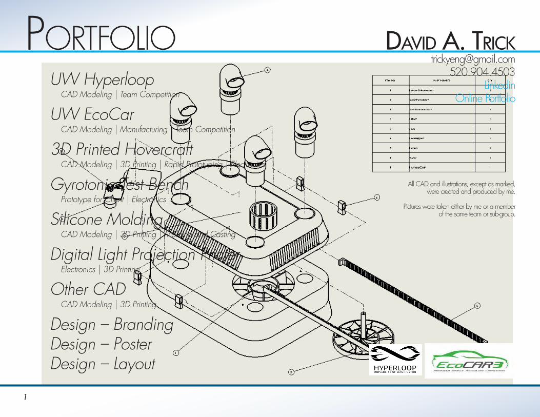
PortfolioUW Hyperloop CAD Modeling | Team Competition
UW EcoCar CAD Modeling | Manufacturing | Team Competition
3D Printed Hovercraft CAD Modeling | 3D Printing | Rapid Prototyping | Electronics
Gyrotonic Test Bench Prototype for Client | Electronics
Silicone Molding CAD Modeling | 3D Printing | Molding and Casting
Digital Light Projection Printer Electronics | 3D Printing
Other CAD CAD Modeling | 3D Printing
Design – BrandingDesign – PosterDesign – Layout
DaviD a. [email protected]
520.904.4503 Linkedin
Online Portfolio
All CAD and illustrations, except as marked, were created and produced by me.
Pictures were taken either by me or a member
of the same team or sub-group.

2
UW HyPerlooPConceptual Sustainable High-Speed Transportation System in which pressurized capsules ride on magnetically induced levitation. Thrust and levitation generated by magnetic eddies induced via a Halbach array of magnets in a circular configuration (the disc in pictures below).• Propulsion Team – Designed a test cell to measure the thrust and lift capabilities of magnetic
propulsion along an unpowered aluminum track by isolating the vectors.
Test Cell - First Version• Stability and frequency damping came from a
cement block/I-beam combination • Measurement of isolated thrust vectors
via strain gauges on a 4”x4” Aluminum Connection Rod
• Design allowed for switching out of testing element for alternate test apparatus (potentially a breaking mechanism)
Test Cell - Second Version• Stability and frequency damping came from structure being bolted to Aluminum Track • Measurement of isolated thrust vectors via gauges connected to thin rods extending parallel to the track.• Design allowed for use of the same track as completed pod testing, used the same linear actuators, and allowed
adjustment of linear actuators for actual running specifications.
UW Team CompetitionIsolated Test Cells Versions 1,2 – CAD
3
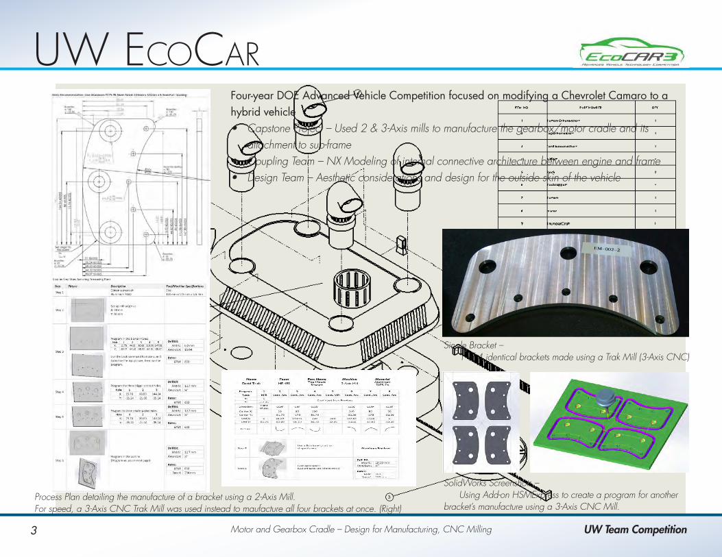
UW ecocarFour-year DOE Advanced Vehicle Competition focused on modifying a Chevrolet Camaro to a hybrid vehicle• Capstone Project – Used 2 & 3-Axis mills to manufacture the gearbox/motor cradle and its
attachment to sub-frame• Coupling Team – NX Modeling of internal connective architecture between engine and frame• Design Team – Aesthetic considerations and design for the outside skin of the vehicle
Motor and Gearbox Cradle – Design for Manufacturing, CNC Milling UW Team Competition
Process Plan detailing the manufacture of a bracket using a 2-Axis Mill. For speed, a 3-Axis CNC Trak Mill was used instead to maufacture all four brackets at once. (Right)
Single Bracket – 1 of 4 identical brackets made using a Trak Mill (3-Axis CNC)
SolidWorks Screenshots – Using Add-on HSMExpress to create a program for another bracket’s manufacture using a 3-Axis CNC Mill.
4
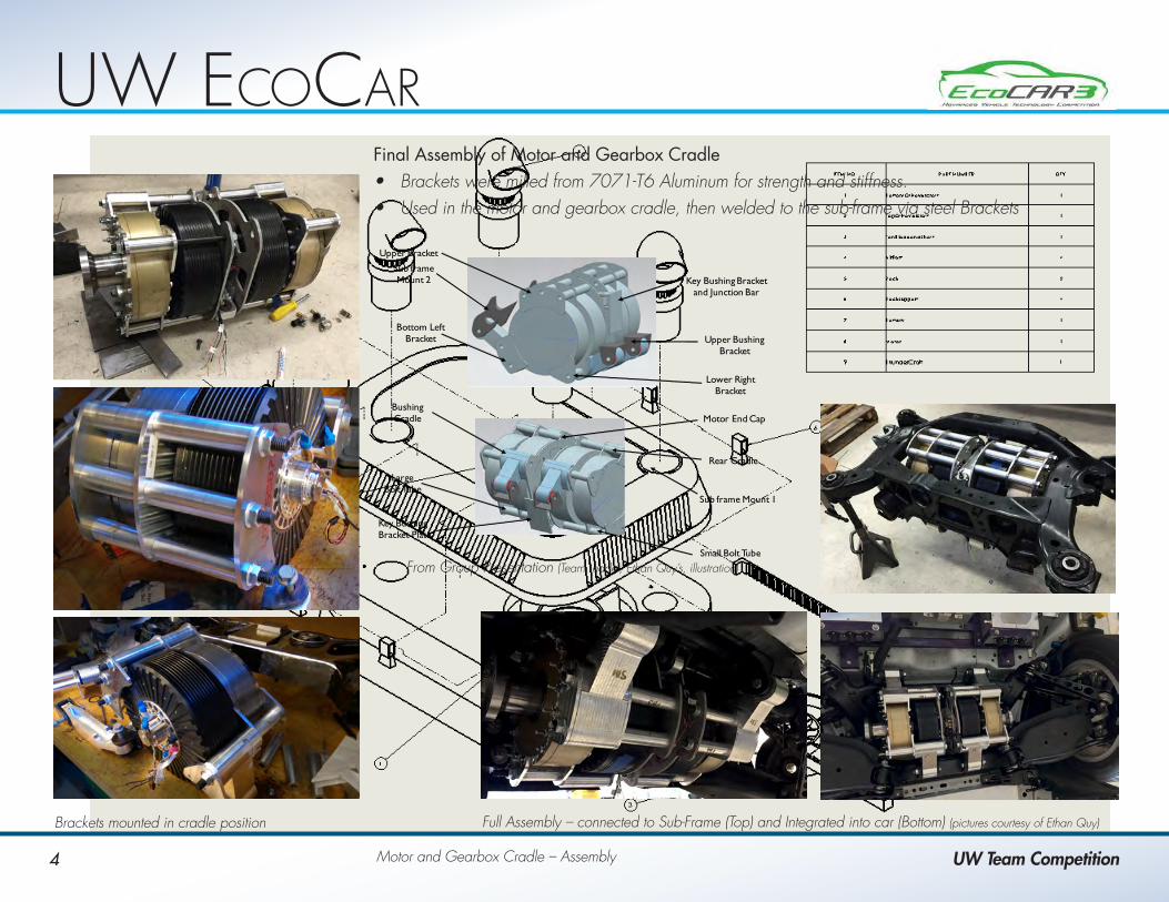
UW ecocarFinal Assembly of Motor and Gearbox Cradle• Brackets were milled from 7071-T6 Aluminum for strength and stiffness.• Used in the motor and gearbox cradle, then welded to the sub-frame via steel Brackets
Motor and Gearbox Cradle – Assembly UW Team Competition
Brackets mounted in cradle position Full Assembly – connected to Sub-Frame (Top) and Integrated into car (Bottom) (pictures courtesy of Ethan Quy)
Upper Bracket
Sub frame Mount 2
Sub frame Mount 1
Bottom Left Bracket
Large Bolt Tube
Bushing Cradle
Small Bolt Tube
Rear Cradle
Motor End Cap
Lower Right Bracket
Upper Bushing Bracket
Key Bushing Bracket Plate
Key Bushing Bracket and Junction Bar
From Group Presentation (Team Leader, Ethan Quy’s, illustration)
5
3D PrinteD Hovercraft
Class Project
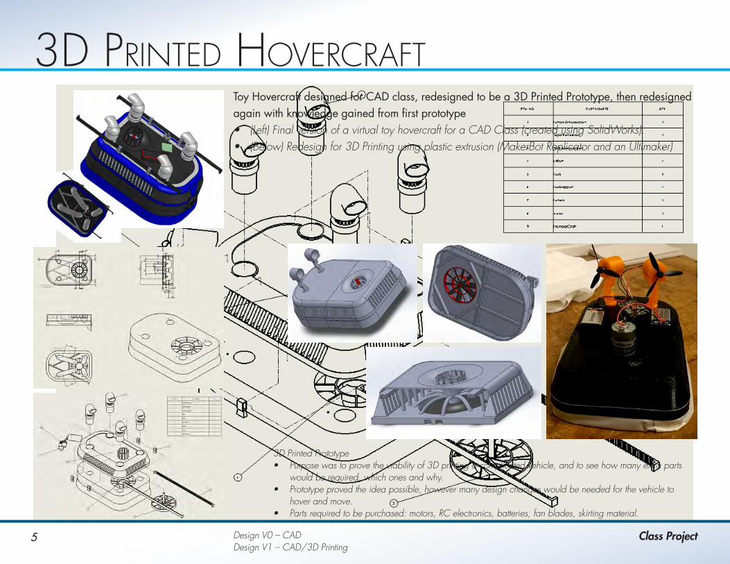
Toy Hovercraft designed for CAD class, redesigned to be a 3D Printed Prototype, then redesigned again with knowledge gained from first prototype• (Left) Final version of a virtual toy hovercraft for a CAD Class (created using SolidWorks).• (Below) Redesign for 3D Printing using plastic extrusion (MakerBot Replicator and an Ultimaker)
3D Printed Prototype• Purpose was to prove the viability of 3D printing a complicated vehicle, and to see how many extra parts
would be required, which ones and why. • Prototype proved the idea possible, however many design changes would be needed for the vehicle to
hover and move.• Parts required to be purchased: motors, RC electronics, batteries, fan blades, skirting material.
Design V0 – CAD Design V1 – CAD/3D Printing

6
3D PrinteD Hovercraft
Personal Project
As a follow-up, I redesigned the toy hovercraft with the knowledge gained from first prototype• (Left) Version 2 – showing the new connection system (tabs and holes) hopefully snap together• (Right) Version 2.5 – Redesigned with more room for the tabs, and adding in a very thin cage for
the directional thrust fans
Version 2 Printing• The tabs and top do not click together• But, the system is smaller, lighter and much easier to print
Version 2.5• The tabs are redesigned to click together easily• Directional motors added with thin cages for safety• Everything is designed to print easily
Version 2, 2.5 – CAD/3D Printed

7
We were the only team to build a complete working prototype of our design concept for lifting the Gyrotonic Exercise bench.Design boundaries and comparison to produced prototype:
Minimum Design Specifications Prototype SpecificationsCould not exceed $500 Total cost was around $250 for the prototype
Had to lift the bench 6” in increments of 2” 6” lift, infinitely adjustable
Fit Aesthetically Wood framing allowed aesthetics to be maintained
No permanent modification Strapped onto body, nothing permanent
Must slide easily and raise the bench no more than .5” When fully retracted, the device was .5” above the ground, allowing for easy movement and no change to height
My Role in Project:• Unofficial Team Lead • Research into possible use of hydraulics
• All of the wiring and testing of the actuators and the two up/off/down switches (three actuators – two front / one rear)
• Contributed to final design of the system• Aided with the carpentry and assembly• Aided in writing the final report• Presented along with the team
Gyrotonic Bench Lifter – Rapid Prototyping, Electronic Wiring, Carpentry
Gyrotonic test BencH
Class Project
For a video showing the Prototype test on the bench please click Here.
A circuit diagram of the switches and power source. Pugh Chart showing the possibilities considered and their ranking compared to the Linear Actuator.
8
silicon MolDinG
Class Project
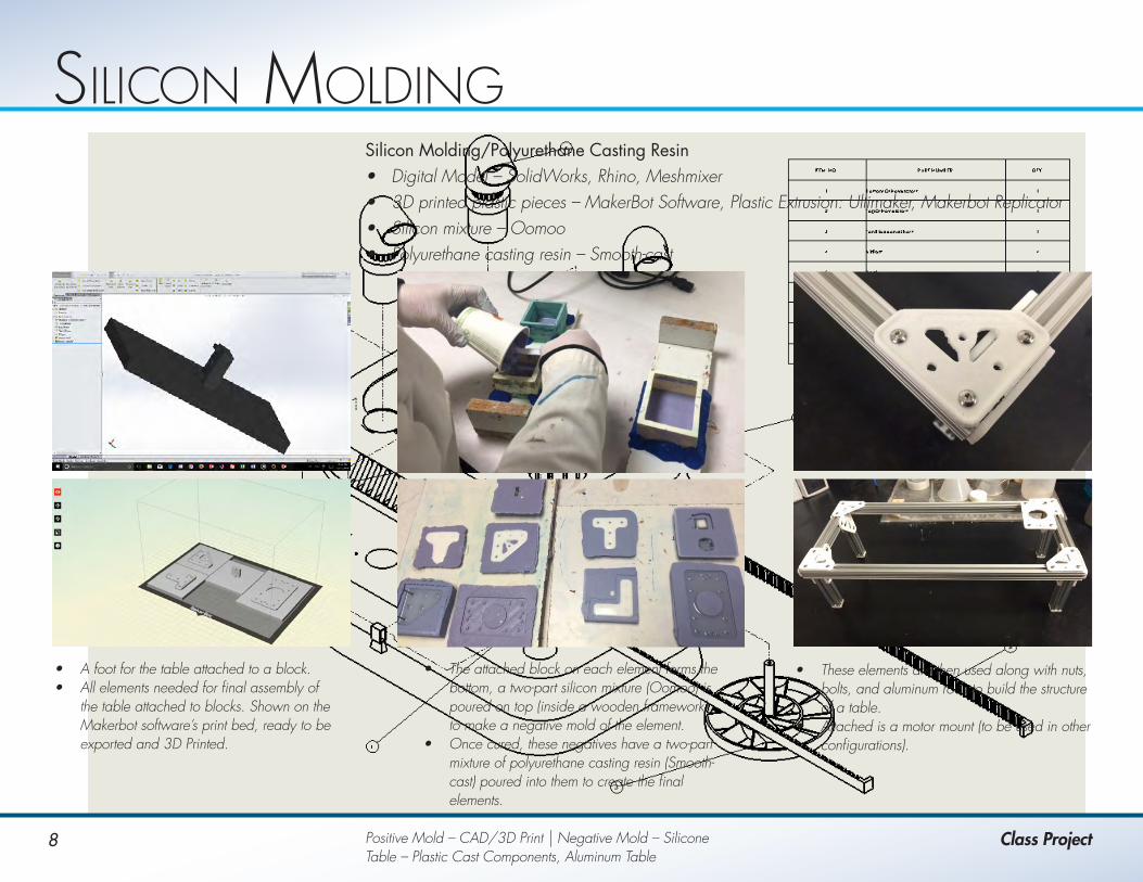
Silicon Molding/Polyurethane Casting Resin• Digital Model – SolidWorks, Rhino, Meshmixer• 3D printed plastic pieces – MakerBot Software, Plastic Extrusion: Ultimaker, Makerbot Replicator• Silicon mixture – Oomoo• Polyurethane casting resin – Smooth-cast
• A foot for the table attached to a block.• All elements needed for final assembly of
the table attached to blocks. Shown on the Makerbot software’s print bed, ready to be exported and 3D Printed.
• The attached block on each element forms the bottom, a two-part silicon mixture (Oomoo) is poured on top (inside a wooden framework) to make a negative mold of the element.
• Once cured, these negatives have a two-part mixture of polyurethane casting resin (Smooth-cast) poured into them to create the final elements.
• These elements are then used along with nuts, bolts, and aluminum rods to build the structure of a table.
• Attached is a motor mount (to be used in other configurations).
Positive Mold – CAD/3D Print | Negative Mold – SiliconeTable – Plastic Cast Components, Aluminum Table
9
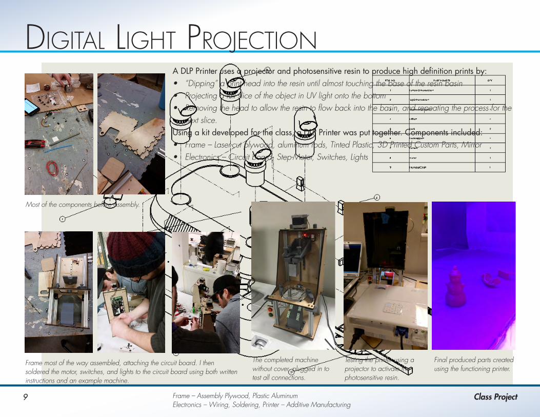
DiGital liGHt ProjectionA DLP Printer uses a projector and photosensitive resin to produce high definition prints by:• “Dipping” a print head into the resin until almost touching the base of the resin basin• Projecting a full slice of the object in UV light onto the bottom• Removing the head to allow the resin to flow back into the basin, and repeating the process for the
next slice.Using a kit developed for the class, a DLP Printer was put together. Components included:• Frame – Laser-cut plywood, aluminum rods, Tinted Plastic, 3D Printed Custom Parts, Mirror• Electronics – Circuit board, Step-Motor, Switches, Lights
Frame – Assembly Plywood, Plastic Aluminum Electronics – Wiring, Soldering, Printer – Additive Manufacturing
Class Project
Most of the components before assembly.
Frame most of the way assembled, attaching the circuit board. I then soldered the motor, switches, and lights to the circuit board using both written instructions and an example machine.
The completed machine without cover, plugged in to test all connections.
Testing the printer using a projector to activate the photosensitive resin.
Final produced parts created using the functioning printer.

10
otHer caD
Class and PersonalCAD – Solar Battery, Pasta Sorter, Greatest Name, Geometric model, Plywood and Acrylic Laser Cut Pieces
CAD Design work, Software used:• SolidWorks CAD Models: Camping Solar Battery, Pasta sorter, Greatest Name• Mathematica Shape generation: Paperweight• Laser-cut Plywood and Acrylic: Greatest Name centerpiece
Camping Solar Battery –• About the size of a briefcase when folded up.• Made to stand on its own • Trickle charges a very big battery (the base).• Many plug-ins for different uses.
Pasta Sorting Machine –• 8 feet long, pasta drops 2 feet• Made to remove big chunks and pasta dust
from a conveyer which deposits it at the top “V” section
Mathematica Geometric Model –• Agglutination of many basic
mathematical formulas for shapes• Exported as a .stl file to be
3D Printed• Shown in the Makerbot Print Bed.
Greatest Name –• Created as a centerpiece for my grandmother’s coffin (seen in lower picture).• CAD model (upper Left) created in SolidWorks and exported piece by piece
to Rhino.• Laser cut into both plywood and acrylic sheeting (Upper Right), family chose
the plywood to mount on the coffin.• Acrylic backing will be removed and a clear epoxy applied to create a
clear final piece.
11
DesiGn – BranDinG
Client and CourseworkLogos/Logo Options, ID Manual
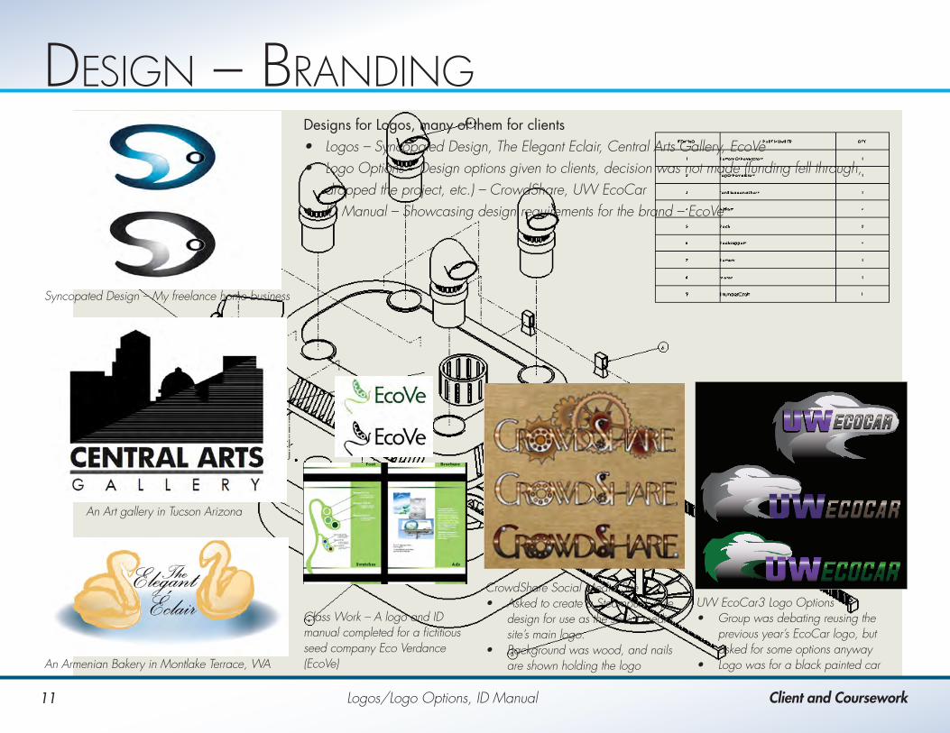
Designs for Logos, many of them for clients• Logos – Syncopated Design, The Elegant Eclair, Central Arts Gallery, EcoVe• Logo Options – Design options given to clients, decision was not made (funding fell through,
dropped the project, etc.) – CrowdShare, UW EcoCar• ID Manual – Showcasing design requirements for the brand – EcoVe
Syncopated Design – My freelance home business
An Armenian Bakery in Montlake Terrace, WA
An Art gallery in Tucson Arizona
Class Work – A logo and ID manual completed for a fictitious seed company Eco Verdance (EcoVe)
CrowdShare Social Media Site• Asked to create a Steampunk style
design for use as the social media site’s main logo.
• Background was wood, and nails are shown holding the logo
UW EcoCar3 Logo Options• Group was debating reusing the
previous year’s EcoCar logo, but asked for some options anyway
• Logo was for a black painted car

12
DesiGn – Poster
Client and CourseworkConcept, Landscape Architecture, Building Layout
Designs for Posters: Concept Posters, Landscape Architecture Posters, and a client-based building layout design poster.• Concept – Planned Obsolescence, Cochin Font Poster.• Landscape Architecture – Class Posters detailing my suggested layouts for the area of the projects.
For more examples of sketches and to see these posters in greater detail please visit my online portfolio.
Highlighting planned obsolescence by examining video game console sales. Bubbles surrounding consoles represent purchases.
Project re-envisioning the University Village Shopping Center in Seattle, WA. • Drawings and sketches show how the shopping center
would be utilized.• Map shows the placement of buildings, a market area,
and trees.• Black lines on the map show where each sketch is
located and what direction is faced
Project reworking Union Bay Natural Area in Seattle, WA. • Drawings and sketches show how the area would be
utilized.• Map shows the placement of buildings, boardwalks,
and trees.• Red lines show where each sketch is located and what
direction is faced
Poster showcasing the Cochin font using the pyramid and text from the Paolo Coelo book “The Alchemist.”
13
DesiGn – layoUt
Client and CourseworkJournal, Building Poster, Booklet
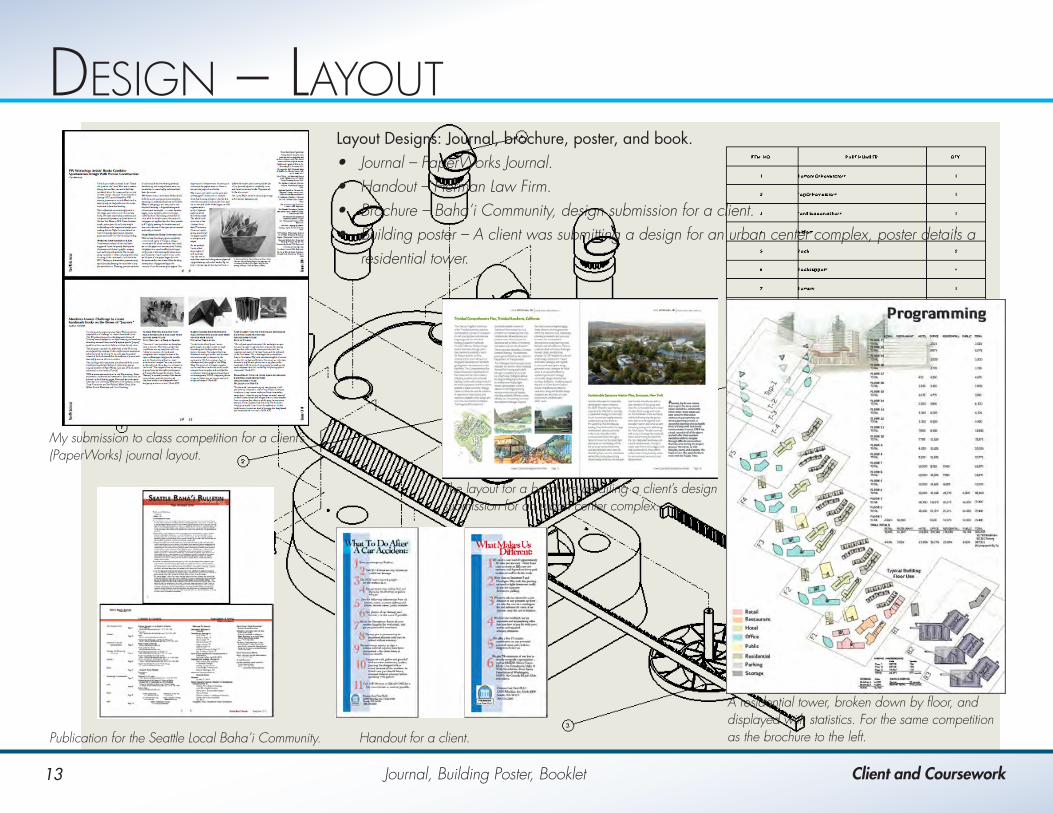
Layout Designs: Journal, brochure, poster, and book.• Journal – PaperWorks Journal.• Handout – Herman Law Firm.• Brochure – Baha’i Community, design submission for a client.• Building poster – A client was submitting a design for an urban center complex, poster details a
residential tower.
My submission to class competition for a client’s (PaperWorks) journal layout.
Handout for a client.Publication for the Seattle Local Baha’i Community.
The layout for a brochure detailing a client’s design submission for an urban center complex.
A residential tower, broken down by floor, and displayed with statistics. For the same competition as the brochure to the left.