magnetic levitation report
TRANSCRIPT

Magnetic Levitation
A
Seminar Report
Submitted in Partial Fulfillment of the Requirements for the Degree
of
Bachelor of Technology
in
Electrical Engineering
Submitted By:
Vasav Shethna (13bee110)
Tushar Shingala (13bee111)
Under Guidance of:
Prof. Hormaz Amrolia
Department of Electrical Engineering
Institute of Technology, Nirma University
Ahmedabad – 382481
April 2015

ACKNOWLEDGEMENT
We have immense pleasure in successful completion of the work titled: ‘MAGNETIC
LEVITATION’. The special environment at Nirma University, Institute of Technology,
Ahmedabad that always supports educational activities, facilitated our work on this presentation.
We greatly appreciate the motivation and understanding extended for the presentation, by Prof. H.
Z. Amrolia and Prof. A. N. Patel, who responded promptly and enthusiastically to our requests for
expertise, despite their congested schedules. We are indebted to all of them, who did their best to
bring improvements through their suggestions.
We thank our Dearest Parents, who encouraged us to extend our reach. With their help and support,
we have been able to complete this work.

ABSTRACT
Magnetic levitation is the use of magnetic fields to levitate a (usually) metallic object.
Manipulating magnetic fields and controlling their forces can levitate an object. Using either
Ferromagnetism or Diamagnetism object can be levitated. A superconductor is perfectly
diamagnetic and electromagnets can exhibit varying levels of ferromagnetism.
Most important application of Magnetic Levitation is Trans-rapid magnetic lift trains and Magnetic
Bearing in order to reduce friction.
Here in this report a detail study of magnetic bearing and maglev trains is given. And also we have
included their advantages disadvantages and future scopes.
LIST OF FIGURES
Figure 1.1 Diamagnetic levitation
Figure 1.2 Magnetic Levitation
Figure 1.3 Magnetic Suspension
Figure 1.4 Maglev Trains
Figure 1.5 Contactless Melting
Figure 1.6 Magnetic Bearing
Figure 1.7 Product Display Purpose
Figure 3.1 Mechanical Constraint
Figure 3.2 Direct Diamagnetic levitation
Figure 3.3 Superconductor Levitation
Figure 3.4 Diamagnetically Stabilized Levitation
Figure 3.5 Rotational Stabilization
Figure 4.1 Plain Bearing
Figure 4.2 Rolling Bearing
Figure 4.3 Operation Diagram
Figure 4.4 Turbo Blower

Figure 4.5 Gas Turbine
Figure 4.6 Prototype Figure
Figure 4.7 Ferrofluid
Figure 4.8 PMB
Figure 5.1 Maglev Train
Figure 5.2 Eric Laithwaite
Figure 5.3 Three functions of maglev trains
Figure 5.4 Types of Trains
Figure 5.5 EMS Technique
Figure 5.6 Gap Sensor
Figure 5.7 EDS Technique
Figure 5.8 Lateral Guidance
Figure 5.9 Vertical Guidance
LIST OF TABLES
Table 5.1 Pros and Cons of Different Technologies

NOMENCLATURE/ABBREVIATIONS
AMB – Active Magnetic Bearing
PMB – Passive Magnetic Bearing
EMS – ElectroMagnetic Suspension
EDS – ElecroDynamic Suspension
LSM – Linear Synchronous Motor
LIM – Linear Induction Motor

TABLE OF CONTENTS
ACKNOWLEDGEMENT III
ABSTRACT IV
LIST OF FIGURES V
LIST OF TABLES VI
NOMENCLATURE/ABBREVIATIONS VII
TABLE OF CONTENTS VIII
CHAPTER 1: Introduction 1
1.1 Definition of Magnetic Levitation 1
1.1.1 Magnetic Levitation
1.1.2 Magnetic Suspension
1
1
1.2 Area of Attraction
1.3 Uses
1.4 Issues
2
2
4
CHAPTER 2: Earnshaw’s Theorem
4
2.1 Statement
2.2 Stability
4
4
CHAPTER 3: Methods For Magnetic Levitation
3.1 Mechanical Constraint
3.2 Direct Diamagnetic Levitation
3.3 Superconductors
3.4 Diamagnetically Stabilized Levitation
3.5 Rotational Stabilization
3.6 Servo Stabilization
3.7 Rotating conductors beneath magnets
3.8 High-Frequency Oscillating Electromagnetic fields
CHAPTER 4: Applications of Magnetic Levitation
4.1 Magnetic Bearing
4.1.1 Meaning of Bearing
4.1.2 Types of Bearing
4.1.3 Magnetic Bearing
4.1.4 Classification of Magnetic Bearing
4.1.5 Active Magnetic Bearing
4.1.6 Application of Active Magnetic Bearing
4.1.7 Advantages and Disadvantages of AMB
4.1.8 PMB
4.1.9 Application of PMB
4.2 Application of Magnetic Bearing
4
4
5
6
6
7
8
9
9
9
9
9
9
10
11
11
12
13
14
16
16
16

CHAPTER 5: Maglev Train
5.1 History of Maglev Trains
5.2 basic Principle of Maglev Trains
5.3 How does it work?
5.4 Types of maglev train
5.4.1 EMS Technique
5.4.2 Gap Sensor
5.4.3 EDS Technique
5.5 Pros and Cons of Different Techniques
5.6 Propulsion
5.6.1 Propulsion Force
5.6.2 Techniques of Propulsion
5.7 Principle of Guidance
5.7.1 Principle of Lateral Guidance
5.7.2 Principle of Vertical Guidance
5.8 Advantages
5.9 Economic Aspect
5.10 Current Projects
16
17
18
18
19
20
20
21
22
22
22
22
22
23
24
24
24
REFERENCES 24
APPENDIX 25
.

CHAPTER 1: Introduction
Figure 1.1 Diamagnetic levitation
1.1 Definition of Magnetic Levitation
Magnetic levitation, maglev or magnetic suspension is a method by which an object is suspended
with no support other than magnetic fields. Magnetic force is used to counteract the effect of
gravitational force.
The Difference between levitation and suspension
1.1.1 Magnetic Levitation: If an object is kept in air using the force of repulsion given from the
bottom of the object then it is known as magnetic levitation.

1.1.2 Magnetic Suspension:
If an object is suspended using the force of attraction applied from top of the object then it is known
as magnetic suspension.
1.2 Area of Attraction:
The main area of attraction in the field of magnetic levitation is as a means of eliminating friction
or physical contact.
As a means of eliminating friction magnetic levitation gives its use in magnetic bearing.
As a means of eliminating physical contact magnetic levitation gives its use in magnetic levitated
trains.
1.3 Uses:
Magnetic levitation finds its application in following applications:
Figure 1.2 Magnetic Levitation
Figure 1.3 Magnetic Suspension

1. Maglev trains: For high speed ground transportation maglev trains are designed to take
advantage of magnetic levitation.
2. Contactless Melting: Metal having high resistance can be levitated and melt in magnetic
field.
3. Magnetic Bearing: For rotating machines to stabilize shaft without friction and contact
magnetic bearing are used.
4. Product Display Purpose: For displaying the product by levitating it in air.
Figure 1.4 Maglev Trains
Figure 1.5 Contactless Melting
Figure 1.6 Magnetic Bearing

1.4 Issues:
Primary issues involved in magnetic levitation are stability and lifting force. Lifting force should
be sufficient to provide upward force to counteract gravity. Stability to ensure that the system does
not slide or flip into a configuration when lift is neutralized.
CHAPTER 2: Earnshaw’s Theorem:
2.1 Statement:
It is impossible for a pole placed in a static field of force to have a position of stable equilibrium
when an inverse square law operates and this fundamental calculation is known as ‘Earnshaw’s
theorem’.
2.2 Stability:
Static Stability:
Static stability means that any small displacement away from a stable equilibrium causes a net
force to push it back to the equilibrium point.
Dynamic Stability:
Dynamic stability occurs when the levitation system is able to damp out any vibration-like motion
that may occur.
CHAPTER 3: Methods for Magnetic Levitation:
For Stable and successful levitation and control of all 6 axes by combination of permanent
magnets, diamagnets, electromagnets and superconductors by using force of attraction or repulsion
can be used. From Earnshaw’s theorem at least one stable axe should be present to levitate an
object.
Figure 1.7 Product Display
Purpose

3.1 Mechanical Constraint:
Mechanical constraint deals with levitation using two permanent magnets. Both magnets are
permanent therefore by Earnshaw’s theorem it can’t be made stable without any external support.
Figure 3.1 Mechanical Constraint
3.2 Direct Diamagnetic Levitation
Direct diamagnetic levitation is done by a diamagnetic material and permanent magnet. It is
because of the property of diamagnetic material to repel magnet.

Figure 3.2 Direct Diamagnetic levitation
3.3 Superconductors:
Superconductors levitates when it kept on magnetic track made using strong magnets and
combination of force of repulsion and attraction.
Figure 3.3 Superconductor Levitation
3.4 Diamagnetically Stabilized levitation:
In this method permanent magnet is levitated using various configuration of diamagnetic materials.

Figure 3.4 Diamagnetically Stabilized Levitation
3.5 Rotational Stabilization:
It is also known as spin stabilized magnetic levitation. Happens when the forces acting on the
levitating object- gravitational, magnetic, and gyroscopic- are in equilibrium. Earnshaw’s theorem
says it is impossible.

Figure 3.5 Rotational Stabilization
3.6 Servo Stabilization:
The attraction from a fixed strength magnet decreases with increased distance, and increases at
closer distances. This is unstable. For a stable system, the opposite is needed, variations from a
stable position should push it back to the target position. Stable magnetic levitation can be achieved
by measuring the position and speed of the object being levitated, and using a feedback loop which
continuously adjusts one or more electromagnets to correct the object's motion, thus forming
a servomechanism.
Maglev Trains uses servo mechanism.

3.7 Rotating conductors beneath magnets:
In this type of method conductors are rotated and because of their rotation it cuts the magnetic flux
and emf induced which opposes main field and hence it levitates.
3.8 High-frequency oscillating electromagnetic fields:
High frequency oscillating electromagnetic fields which are created by ac current, induces eddy
currents in conducting material and levitates it.
CHAPTER 4: Applications of Magnetic Levitation
Magnetic Bearing
Maglev Train
Maglev wind turbine
Maglev Fan
StartRam
Flying Car
Flywheels
4.1 Magnetic Bearing
4.1.1 Meaning of Bearing
A device which is used to enable linear or rotational motion of the shaft while reducing
friction is called bearing. It provides stability to the rotating shaft and frictionless rotation
of the same. The contacting surfaces in a bearing may be partially or completely separated
by a film of oil or any other liquid in order to reduce friction.
4.1.2 Types of Bearing
(a) Plain or Slider Bearing
In which the rotating shaft has a sliding contact with the bearing which is held stationary.
Due to large contact area friction between mating parts is high requiring greater lubrication.

Figure 4.1 Plain Bearing
(b) Rolling or Antifriction Bearing
Due to less contact area rolling friction is much lesser than the sliding friction, hence these
bearings are also known as antifriction bearing.
Figure 4.2 Rolling Bearing
4.1.3 Magnetic Bearing.
A magnetic bearing system supports a rotating shaft, without any physical contact by
suspending the rotor in the air, with an electrically controlled magnetic force. It works on
the basic principle of Magnetic Levitation and Electromagnetism. We can call it as the
future for upcoming generation of motors.

Hence we can say Magnetic bearings are designed to support rotating and linear moving
machinery elements without contact with rotor, this is accomplished by Electro-magnet
(bearing) which attracts a Ferromagnetic material (rotor) , using this principle rotor can be
suspended in magnetic field which is generated by bearing.
Main components of magnetic bearing are Actuators, Sensors and Control Mechanism.
4.1.4 Classification of Magnetic Bearing
a) Based on control action
b) Based on Forcing Action:
c) Based on load supported:
d) Based on magnetic effect:
Based on magnetic effect it can be classified in attractive type and repulsive type of
bearings.
4.1.5 Active Magnetic Bearing:
Because of Earnshaw’s Theorem it is not possible to use permanent magnets in magnetic
bearing. Even techniques that deal with diamagnets are under-developed. Hence
electromagnets are used for magnetic bearing. Hence magnetic bearing requires a
continuous power input & control system to stable the load. Even back-up powering is
required in case of power failure.
4.1.5.1 Operation
An Active Magnetic Bearing (AMB) consists of an electromagnet assembly, a set of power
amplifiers which supply current to the electromagnets, a controller, and gap sensors with
associated electronics to provide the feedback required to control the position of the rotor
within the gap. The power amplifiers supply equal bias current to two pairs of
electromagnets on opposite sides of a rotor.
The controller offsets the required bias current by equal but opposite perturbations of
current as the rotor deviates by a small amount from its center position. The gap sensors
are usually inductive in nature and continuously sensing the gap between rotor and the
bearing. The sensor measures the position of the body. The control electronics then
calculates the right current to suspend the ball.
This current is set by the amplifier. The resulting force is within limits proportional to the
square of the current and inversely proportional to the square of the position.
F = (I/X)^2
Controller uses Microprocessor to allow the whole system function in a stable manner.

Figure 4.3 Operation Diagram
4.1.5.2 Digital control System:
A-D converter Control Algorithm Processor D-A Converter
E.g. The position, is sampled. The data serves as input of the control algorithm, which runs
on the processor. Then the calculated desired value is converted into an analog form.
According to the application the data width lies between 10 and 64 bits.
4.1.6 Application of Active Magnetic Bearing
Turbo-blower: cooling gas compressor (CO2) for a power laser, cutting metal sheets up to
25 mm. The laser needs uncontaminated gas.
The speed is 54000 rpm, the rotor mass 3.6 kg, the motor power 12 kW.

Figure 4.4 Turbo Blower
Gas-turbine/Generator for power generation: 4 radial bearings and 1 thrust bearing, 6010
rpm, 9000 kW, bearing diameter 400 mm.
Figure 4.5 Gas Turbine
4.1.7 Advantages and Disadvantages of AMB:
Advantages:
o Magnetic Bearings are free of contact and can be utilized in vacuum techniques,
clean and sterile rooms and transportation of aggressive media or pure media.

o Highest speeds are possible even till the ultimate strength of the rotor.
o Absence of lubrication seals allows the larger and stiffer rotor shafts.
o Absence of mechanical wear results in lower maintenance costs and longer life of
the system.
Disadvantages:
High cost and larger in size.
4.1.8 Passive Magnetic Bearing (PMB):
Passive Magnetic Bearing differs from AMB in terms of magnets and electronic system.
The rotor is stabilized only by permanent uncontrolled magnetic fields. Because of this
PMB are less expensive than AMB.
Background:
PMB can be constructed using:
Permanent magnets.
Ferrofuilds(A liquid that gets strongly energized under magnetic field).
Diamagnetic materials eg copper, gold, quartz, mercury, water, alcohol.
Shown Prototype is built at GLENN RESEARCH CENTER.
Figure 4.6 Prototype Figure

Figure 4.7 Ferrofluid
Figure 4.8 PMB
4.1.9 Application of PMB
As far as the application is concerned it is limited as the diamagnetic or the permanent
magnets can be damaged easily.
It can only be used in application of flywheels.
First PMB bearing was prepared at GLENN RESEARCH CENTER at the speed of
5500rpm.
Disadvantage of PMB is Permanent Magnets are used hence they can be easily damaged
due to hammering or overheating. Therefore they are not economical.
4.2 Application of Magnetic Bearing:
• Used in industrial machines like compressors, turbines, pumps, motors and generators.
• Can be used in watt-hour meter to measure home power consumption.
• Useful in high precision equipment & to support equipment in a vacuum.
• To support maglev trains for smooth & noise free ride.
• Useful in artificial heart.
• Anywhere where rotating part is used
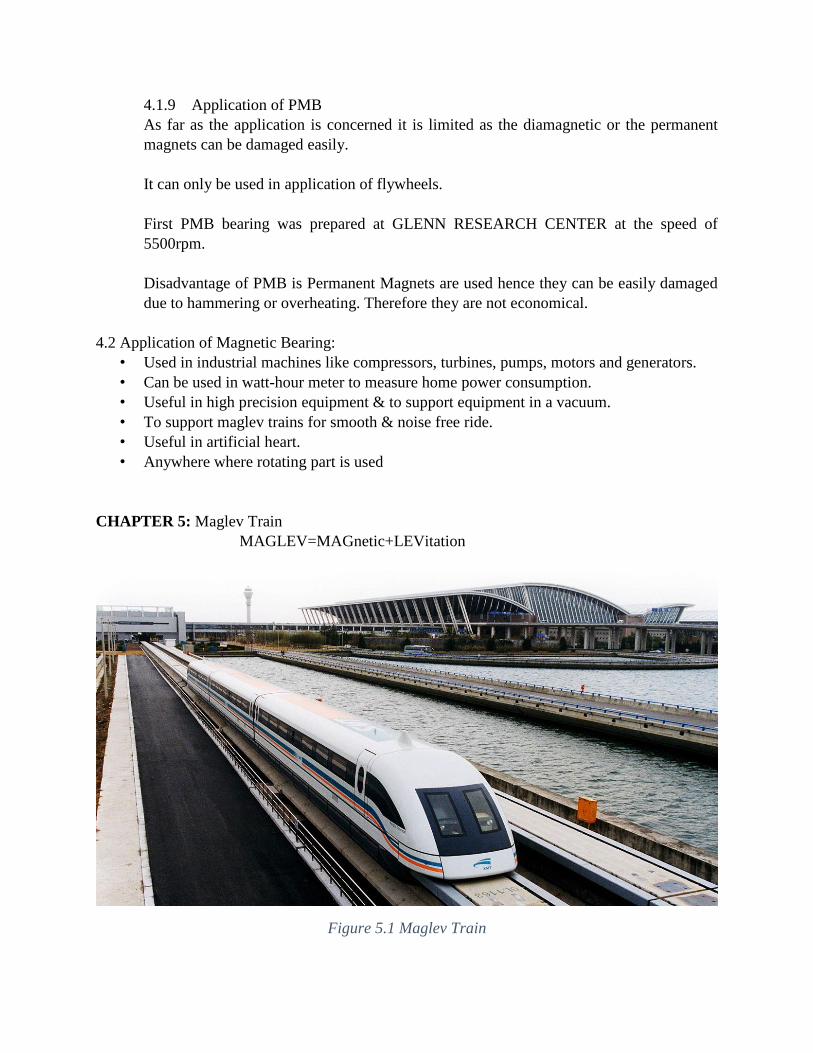
CHAPTER 5: Maglev Train
MAGLEV=MAGnetic+LEVitation
Figure 5.1 Maglev Train

5.1 History of Maglev trains:
In the 1960s in Britain Eric Laithwaite developed a functional maglev train. His maglev had 1.6
km of track and was in detail tested. His research was stopped in 1973 because lack of money and
his progress was not enough. In the 1970s, Germany and Japan also began research and after some
failures both nations developed mature technologies in the 1990’s.
Figure 5.2 Eric Laithwaite
5.2 Basic Principle Maglev Trains:
Maglev trains have to perform the following function to operate in high speed.
1. Levitation
2. Propulsion
3. Guidance

Figure 5.3 Three functions of maglev trains
5.3 How does it work?
A maglev train floats about 10mm above the guide way on a magnetic field.
It is propelled by the guideway itself rather than an onboard engine by changing magnetic fields.
Once the train is pulled into the next section the magnetism switches so that the train is pulled on
again. The Electro-magnets run the length of the guideway.
5.4 Types of Maglev Trains:
Based on the technique used for Levitation the are two types of Maglev trains
1. Electromagnetic Suspension - Attractive
2. Electrodynamic Suspension – Repulsive

Figure 5.4 Types of Trains
5.4.1 EMS Technique
In the EMS-attractive system, the electromagnets which do the work of levitation are attached on
the top side of a casing that extends below and then curves back up to the rail that is in the center
of the track.
Figure 5.5 EMS Technique

5.4.2 Gap Sensor
This attractive force is controlled by a gap sensor that measures the distance between the rails
and electromagnets.
Figure 5.6 Gap Sensor
5.4.3 EDS Technique
Electrodynamic Suspension uses Superconductors for levitation, propulsion and lateral guidance.

Figure 5.7 EDS Technique
5.5 Pros and Cons of Different Technologies
Table 5.1 Pros and Cons of Different Technologies
Technology Pros Cons
EMS
(Electromagnetic suspension)
Magnetic fields inside and
outside the vehicle are less
than EDS; proven,
commercially available
technology that can attain
very high speeds (500 km/h);
no wheels or secondary
propulsion system needed
The separation between the
vehicle and the guideway
must be constantly monitored
and corrected by computer
systems to avoid collision due
to the unstable nature of
electromagnetic attraction;
due to the system's inherent
instability and the required
constant corrections by
outside systems, vibration
issues may occur.
EDS
(Electrodynamic suspension)
Onboard magnets and large
margin between rail and train
enable highest recorded train
speeds (581 km/h) and heavy
load capacity; has recently
demonstrated (December
2005) successful operations
using high temperature
Strong magnetic fields
onboard the train would make
the train inaccessible to
passengers with pacemakers
or magnetic data storage
media such as hard drives and
credit cards, necessitating the
use of magnetic shielding;

superconductors in its
onboard magnets, cooled with
inexpensive liquid nitrogen
limitations on guideway
inductivity limit the maximum
speed of the vehicle; vehicle
must be wheeled for travel at
low speeds.
5.6 Propulsion:
The propulsion coils located on the sidewalls on both sides of the guideway are energized by a
three-phase alternating current from a substation, creating a shifting magnetic field on the
guideway.
The on-board superconducting magnets are attracted and pushed by the shifting field, propelling
the Maglev vehicle.
Braking is accomplished by sending an alternating current in the reverse direction so that it is
slowed by attractive and repulsive forces.
5.6.1 Propulsion Force:
This is a horizontal force which causes the movement of train. It requires 3 parameters.
i. Large electric power supply
ii. Metal coil lining, a guide way or track.
iii. Large magnet attached under the vehicle.
5.6.2 Techniques of propulsion:
Maglev vehicles are propelled primarily by one of the following three options:
a. Linear synchronous motor (LSM) in which coils in the guide way are excited by a
three phase winding to produce a traveling wave at the speed desired; Trans Rapid in
Germany employs such a system.
b. Linear Induction Motor (LIM) in which an electromagnet underneath the vehicle
induces current in an aluminium sheet on the guide way.
c. Reluctance motor is employed in which active coils on the vehicle are pulsed at the
proper time to realize thrust.
5.7 Principle of Guidance:
5.7.1 Principle of Lateral Guidance:
When one side of the train nears the side of the guideway, the super conducting magnet on the
train induces a repulsive force from the levitation coils on the side closer to the train and an
attractive force from the coils on the farther side.
This keeps the train in the center.

Figure 5.8 Lateral Guidance
5.7.2 Principle of Vertical Guidance:
The electromagnets on the underside of the train pull it up to the ferromagnetic stators on the track
and levitate the train.
The magnets on the side keep the train from moving from side to side.
Figure 5.9 Vertical Guidance

5.8 Advantages:
• The train is earthquake proof because the greater space (10 cm) between the track and the
train leaves more room for track deformation.
• Only the part of the track that is used will be electrified so no energy is wasted.
• Its top speed with people aboard is 350 mph.
• Since there is no friction these trains can reach high speeds.
• It is a safe and efficient way to travel.
5.9 Economic Aspect:
• The initial investment is similar to other high speed rail roads.
• Operating expenses are half of that of other railroads.
• A train is composed of sections that each contain 100 seats, and a train can have between
2 and 10 sections.
• The linear generators produce electricity for the cabin of the train, Thus it also consumes
the energy.
5.10 Current Projects:
• Currently operational systems include Transrapid (Germany) and High Speed Surface
Transport (Japan). There are several other projects under scrutiny such as the SwissMetro,
Seraphim and Inductrack. All have to do with personal rapid transit.
• Germany and Japan have been the pioneering countries in MagLev research.
References:
• Introduction to magnetic bearing by JAGU SRINIVASA RAO (Pdf)
• Magnetic Bearings by HILLYARD (Pdf)
• Design and Control of Active Magnetic Bearing Systems for High Speed Rotation by
RENE LARSONNEUR (Pdf)
• PMB by Gerhard Schweitzer (PDF)
• Optimization of Repulsive Passive Magnetic Bearings Roland Moser, Jan Sandtner, and
Hannes Bleule1.
• http://en.wikipedia.org/wiki/MAGLEV_TRAIN
• J. Powell, G. Maise, and J. Paniagua, “MAGLEV: A new concept for very low cost
transportation using technique of magnetic levitation,” paper IAF-01-S.6.04, 52nd
International Astronautical Congress, Toulouse, France, Oct. 1-5, 2001.