linear ic aplications
TRANSCRIPT

RCEW, Pasupula (V), Nandikotkur Road,
Near Venkayapalli, KURNOOL
By
N.GEETHA RANI
Associate Professor
Department of ECE
LINEAR IC APLICATIONS
III YEAR I SEMESTER
UNIT - IV
555 TIMER
• 555 timer is an integrated circuit that very stable.
• Use as monostable multivibrator, astablemultivibrator, analog square wave signal generator, achometer frequency meter and others.
• Basically, 555 timer operate in 2 mode,– Monostable
– Astable
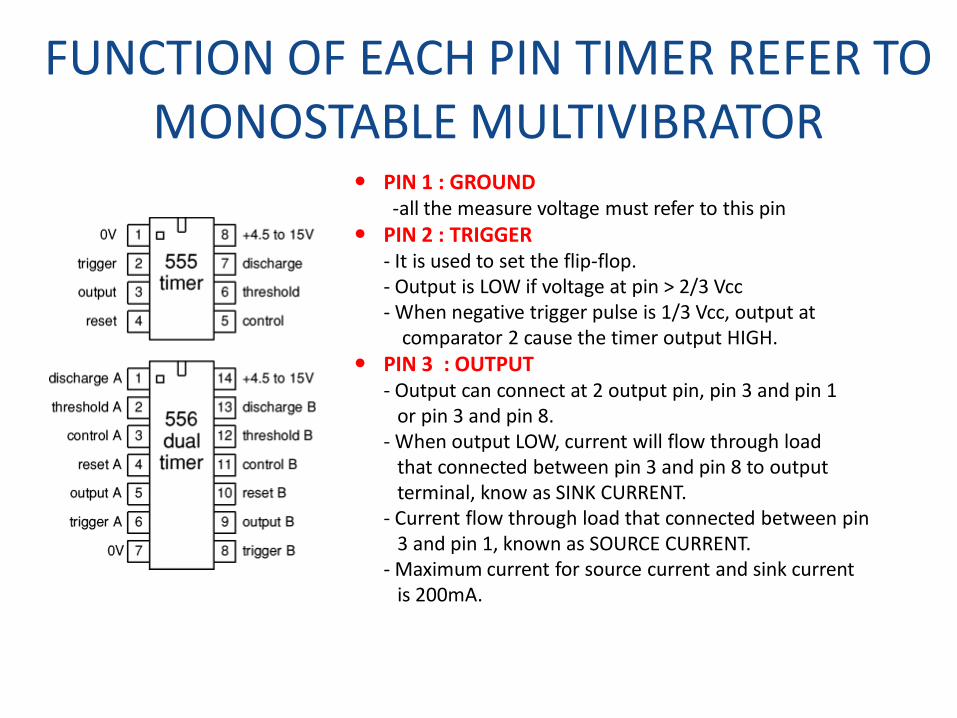
FUNCTION OF EACH PIN TIMER REFER TO MONOSTABLE MULTIVIBRATOR
PIN 1 : GROUND -all the measure voltage must refer to this pin
PIN 2 : TRIGGER- It is used to set the flip-flop. - Output is LOW if voltage at pin > 2/3 Vcc- When negative trigger pulse is 1/3 Vcc, output at
comparator 2 cause the timer output HIGH.
PIN 3 : OUTPUT- Output can connect at 2 output pin, pin 3 and pin 1
or pin 3 and pin 8.- When output LOW, current will flow through load
that connected between pin 3 and pin 8 to outputterminal, know as SINK CURRENT.
- Current flow through load that connected between pin 3 and pin 1, known as SOURCE CURRENT.
- Maximum current for source current and sink current is 200mA.
CONTINUE…..• PIN 4 : RESET
- Reset with negative pulse
- When the reset pin is not used, the pin is connected to +Vs to avoid false trigger.
• PIN 5 : CONTROL VOLTAGE- Normally is connected to earth through 0.01µF capacitor
- If output voltage is connected to pin 5, the output waveform bandwidth can be
changed.
- 0.01µF capacitor can avoid from noise problem.
• PIN 6 : THRESHOLD VOLTAGE- Input for inverting pin at comparator 1
- When voltage at this pin ≥2/3 Vcc, output at comparator 1 is HIGH, output timer
LOW.
• PIN 7 : DISCHARGE- This pin is connected internally to collector at transistor Q1.
- When output HIGH, Q1 OFF, circuit open
- When output LOW, Q1 saturated capacitor C discharge through Q1.
• PIN 8 : SUPPLY VOLTAGE, Vcc- +5 V to 18V
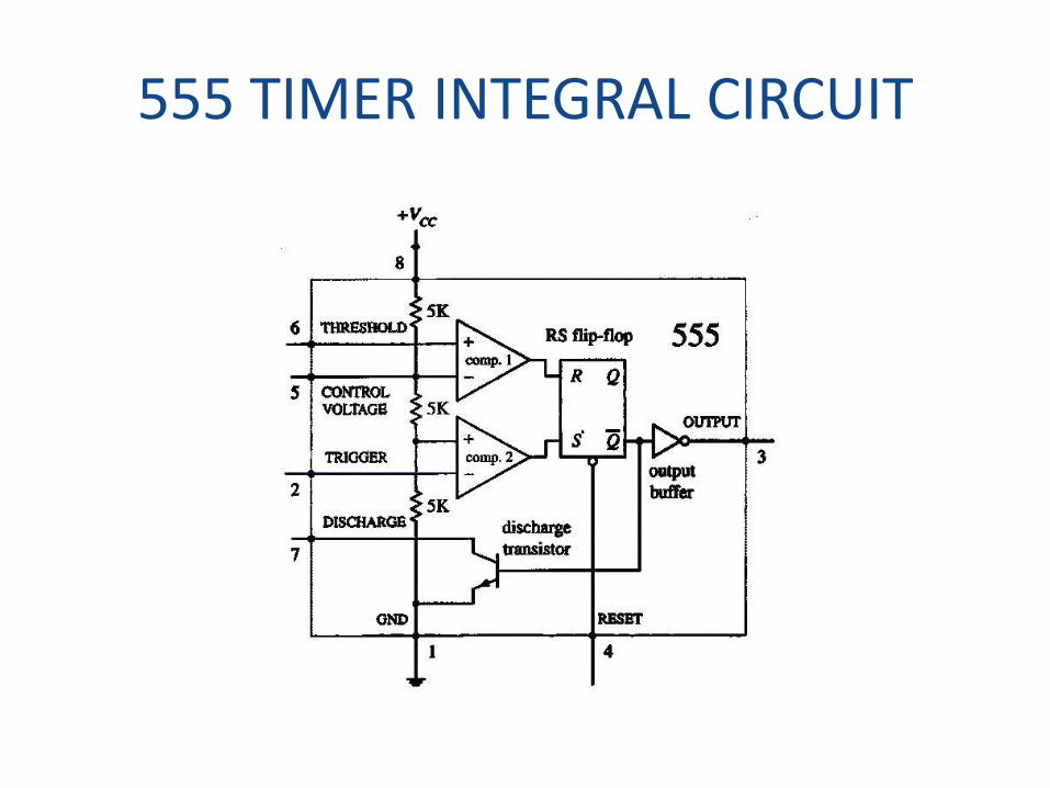
555 TIMER INTEGRAL CIRCUIT
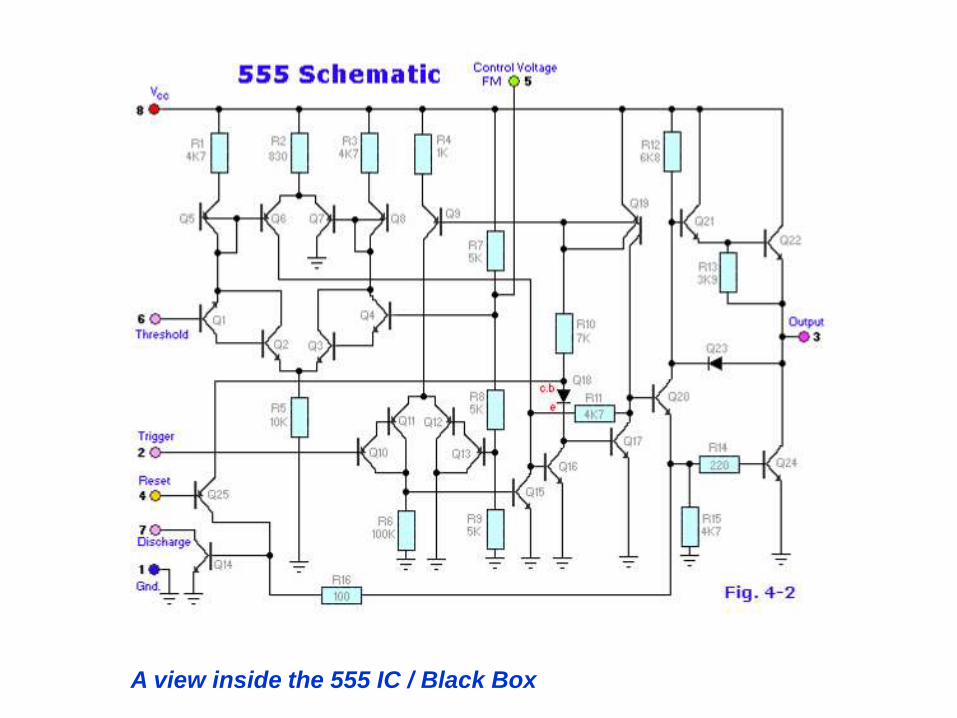
A view inside the 555 IC / Black Box
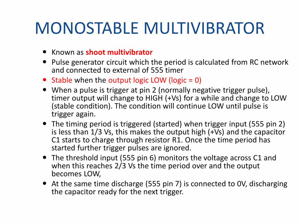
MONOSTABLE MULTIVIBRATOR Known as shoot multivibrator Pulse generator circuit which the period is calculated from RC network
and connected to external of 555 timer Stable when the output logic LOW (logic = 0) When a pulse is trigger at pin 2 (normally negative trigger pulse),
timer output will change to HIGH (+Vs) for a while and change to LOW (stable condition). The condition will continue LOW until pulse is trigger again.
The timing period is triggered (started) when trigger input (555 pin 2) is less than 1/3 Vs, this makes the output high (+Vs) and the capacitor C1 starts to charge through resistor R1. Once the time period has started further trigger pulses are ignored.
The threshold input (555 pin 6) monitors the voltage across C1 and when this reaches 2/3 Vs the time period over and the output becomes LOW,
At the same time discharge (555 pin 7) is connected to 0V, discharging the capacitor ready for the next trigger.
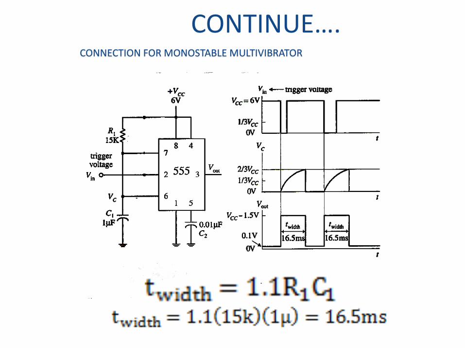
CONTINUE….CONNECTION FOR MONOSTABLE MULTIVIBRATOR

CONTINUE…. Operation for monostable multivibrator :
¤ Assume initial output is LOW, circuit at stable condition, transistor Q1 ON, capacitor is connected to ground.
¤ When negative pulse is triggered to PIN 2 , transistor Q1 OFF (Q1 open circuit), capacitor C start charging through resistor R1 and output is HIGH.
¤ When voltage at capacitor, C reach 2/3 Vs, output will change to LOW through flip flop. At the same time, flip flop output will make the Q1 ON. Capacitor will discharge through transistor Q1.
¤ Monostable output will remain LOW until another trigger pulse is triggered to pin 2.
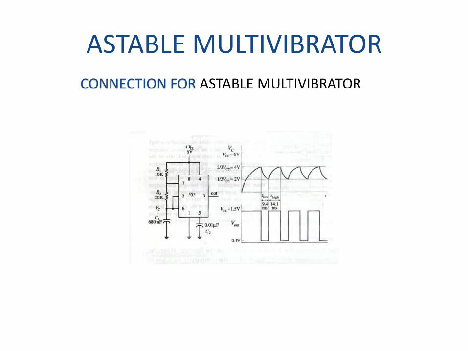
ASTABLE MULTIVIBRATORCONNECTION FOR ASTABLE MULTIVIBRATOR
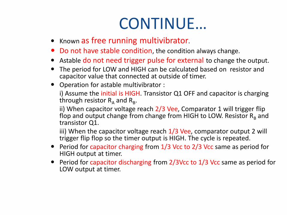
CONTINUE… Known as free running multivibrator.
Do not have stable condition, the condition always change.
Astable do not need trigger pulse for external to change the output. The period for LOW and HIGH can be calculated based on resistor and
capacitor value that connected at outside of timer. Operation for astable multivibrator :
i) Assume the initial is HIGH. Transistor Q1 OFF and capacitor is charging through resistor RA and RB.ii) When capacitor voltage reach 2/3 Vee, Comparator 1 will trigger flip flop and output change from change from HIGH to LOW. Resistor RB and transistor Q1.iii) When the capacitor voltage reach 1/3 Vee, comparator output 2 will trigger flip flop so the timer output is HIGH. The cycle is repeated.
Period for capacitor charging from 1/3 Vcc to 2/3 Vcc same as period for HIGH output at timer.
Period for capacitor discharging from 2/3Vcc to 1/3 Vcc same as period for LOW output at timer.
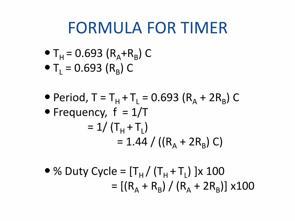
FORMULA FOR TIMER
TH = 0.693 (RA+RB) C TL = 0.693 (RB) C
Period, T = TH + TL = 0.693 (RA + 2RB) C Frequency, f = 1/T
= 1/ (TH + TL) = 1.44 / ((RA + 2RB) C)
% Duty Cycle = [TH / (TH + TL) ]x 100= [(RA + RB) / (RA + 2RB)] x100