limit gauges
TRANSCRIPT


4. According to their purposes :
(a) Workshop Gauge: To Check Dimension after manufacture
(b) Inspection Gauge: To check part before final acceptance
(d) Purchase Inspection Gauge: To check part of other factory
(c) Reference or master gauges: To check the dimension of Gauge

Thursday, February 19, 2015 5
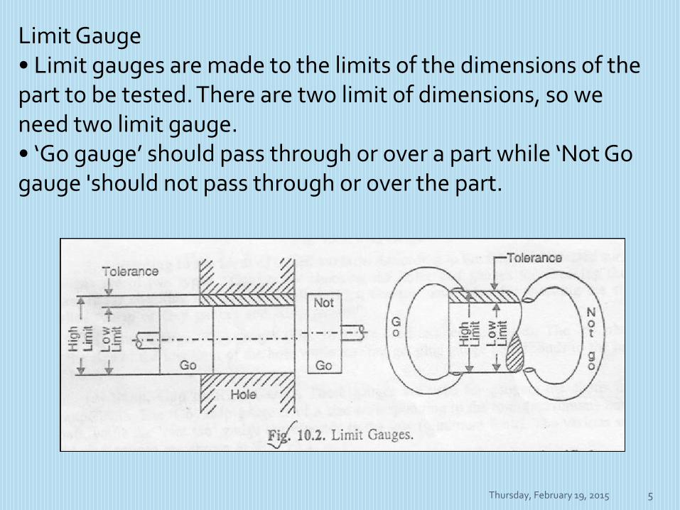
Limit Gauge• Limit gauges are made to the limits of the dimensions of the part to be tested. There are two limit of dimensions, so we need two limit gauge.• ‘Go gauge’ should pass through or over a part while ‘Not Go gauge 'should not pass through or over the part.


Thursday, February 19, 2015 7
Design of Limit Gauge• Allocation of Tolerance– Manufacturing Tolerance– Wear Allowance• Taylor’s Principle of gauge Design• Fixing of Gauge elements with handles– Taper lock design– Trilock Design• Provision of Guards• Provision of Pilot Correct Centering• Materials• Hardness and Surface finish• Rigidity• Alignment of Gauge faces

Thursday, February 19, 2015 8
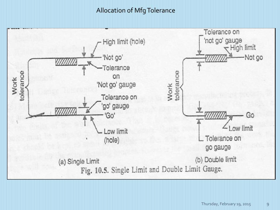
Allocation of ToleranceManufacturing Tolerance• It is economically impractical to attempt to make “Go” and “Not Go” gauges exactly to the two limits of work tolerance.
• Limit gauges are made 10 times more accurate than the tolerances they are going to control.
Thursday, February 19, 2015 9
Allocation of Mfg Tolerance
Thursday, February 19, 2015 10
Allocation of ToleranceWear Allowance
• The surface of “Go” gauge is constantly rubagainst the surface of the part in inspection and loose their initial size.
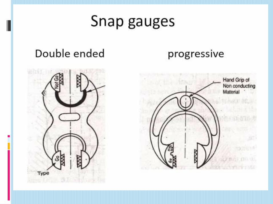
• The size of plug gauge is reduced but size of snap gauge is increased.
• 10% wear allowance is provided only for the “GO” gauge if working tolerance is greater than 0.09 mm.


Materials which are used for making gauges are high carbon and alloy steels, cemented carbides, etc.

Plug Gauges : These are used for checking holes of manydifferent shapes and sizes.Ring Gauges : External diameter measuring gauges.Taper Gauges : Taper testing gauges.Snap Gauges : These are used for checking shafts.Thread Gauges : These are used for pitch diameter of thethread.Form Gauges : These are used to check the contour of aprofile.Feeler Gauges : For checking the clearance between themating surfaces.Indicating Gauges : To measure the position of thesurfaces.


Thursday, February 19, 2015 20
Classification of Plain Gauge
According to the form of the tested surface :(a) Plug gauges for checking holes.
(b) Snap and ring gauges for checking shafts.


TAPER GAUGE
The most satisfactory method of testing a taper is to use taper gauges.
They are also used to gauge the diameter of the taper at some point.
Taper gauges are made in both the plug and ring styles and, in general, follow the same standard construction as plug and ring gauges.


THREAD GAUGE
Thread gauges are used to check the pitch diameter of the thread.
For checking internal threads (nut, bushes, etc.), plug thread gauges are used, while for checking external threads (screws, bolts, etc.), ring thread gauges are used.
Single-piece thread gauges serve for measuring small diameters.
For large diameters the gauges are made with removable plugs machined with a tang.


FORM GAUGE
Form gauges may be used to check the contour of a profile of work piece for conformance to certain shape or form specifications.
Template Gauge
It is made from sheet steel. It is also called profile gauge. A profile gauge may contain two outlines that represent the limits within which a profile must lie


SCREW PITCH GAUGE
Screw pitch gauges areused in picking out a required screw and for checking the pitch of the screw threads.
They consist of a number of flat blades which are cut out to a given pitch and pivoted in a holder.
Each blade is stamped with the pitch or number of thread per inch and the holder bears an identifying number designing the thread it is intended for.

RADIUS AND FILLET GAUGE
The function of these gauges is to check the radius of curvature of convex and concave surfaces over a range from 1 to 25 mm.
The gauges are made in sets of thin plates curved to different radius at the ends.
Each set consists of 16 convex and 16 concave blades.


FEELER GAUGE
Feeler gauges are used for checking clearances between mating surfaces.
They are made in form of a set of steel, precision machined blade 0.03 to 1.0 mm thick and 100 mm long.
Each blade has an indication of its thickness.
To find the size of the clearance, one or two blades are inserted and tried for a fit between the contacting surfaces until blades of suitable thickness are found.


INDICATING GAUGES
Indicating gauges employ a means to magnify how much a dimension deviates, plus or minus, from a given standard to which the gauge has been set.
They are intended for measuring errors in geometrical form and size, and for testing surfaces for their true position with respect to one another.
Indicating gauges can be of a dial or lever type.