lighting controls patterns for design
TRANSCRIPT
7/21/2019 Lighting Controls Patterns for Design
http://slidepdf.com/reader/full/lighting-controls-patterns-for-design 1/299
Lighting Controls: Patterns for Design
Patterns for Design
Technical Repor

7/21/2019 Lighting Controls Patterns for Design
http://slidepdf.com/reader/full/lighting-controls-patterns-for-design 2/299
7/21/2019 Lighting Controls Patterns for Design
http://slidepdf.com/reader/full/lighting-controls-patterns-for-design 3/299
Lighting ControlsPatterns for Design
TR-107230
Final Report, December 1996
Prepared byR. A. Rundquist Associates
56 Ward AvenueNorthampton. MA 01060
AuthorsR.A. RundquistT.G. McDougallJ. Benya
Prepared forEmpire State Electric Energy Research Corporation1515 Broadway, 43
rd Floor
New York, New York 10036-5701
ESEERCO Project ManagersE.M. McCaffreyE. Torrero
Electric Power Research Institute3412 Hillview AvenuePalo Alto, California 94304
EPRI Project ManagerK.F. Johnson
Commercial Business UnitCustomer Systems Group

7/21/2019 Lighting Controls Patterns for Design
http://slidepdf.com/reader/full/lighting-controls-patterns-for-design 4/299
DISCLAIMER OF WARRANTIES AND LIMITATION OF LIABILITIES
THIS REPORT WAS PREPARED BY THE ORGANIZATION(S) NAMED BELOW AS AN ACCOUNT OF WORKSPONSORED OR COSPONSORED BY THE ELECTRIC POWER RESEARCH INSTITUTE, INC. (EPRI).NEITHER EPRI, ANY MEMBER OF EPRI, ANY COSPONSOR, THE ORGANIZATION(S) BELOW, NOR ANYPERSON ACTING ON BEHALF OF ANY OF THEM:
(A) MAKES ANY WARRANTY OR REPRESENTATION WHATSOEVER, EXPRESS OR IMPLIED, (I) WITHRESPECT TO THE USE OF ANY INFORMATION, APPARATUS, METHOD, PROCESS, OR SIMILAR ITEMDISCLOSED IN THIS REPORT, INCLUDING MERCHANTABILITY AND FITNESS FOR A PARTICULARPURPOSE, OR (II) THAT SUCH USE DOES NOT INFRINGE ON OR INTERFERE WITH PRIVATELY OWNEDRIGHTS, INCLUDING ANY PARTY'S INTELLECTUAL PROPERTY, OR (III) THAT THIS REPORT IS SUITABLETO ANY PARTICULAR USER'S CIRCUMSTANCE; OR
(B) ASSUMES RESPONSIBILITY FOR ANY DAMAGES OR OTHER LIABILITY WHATSOEVER (INCLUDINGANY CONSEQUENTIAL DAMAGES, EVEN IF EPRI OR ANY EPRI REPRESENTATIVE HAS BEEN ADVISEDOF THE POSSIBILITY OF SUCH DAMAGES) RESULTING FROM YOUR SELECTION OR USE OF THISREPORT OR ANY INFORMATION, APPARATUS, METHOD, PROCESS, OR SIMILAR ITEM DISCLOSED INTHIS REPORT.
ORGANIZATION(S) THAT PREPARED THIS REPORT
R. A. RUNDQUIST ASSOCIATES
ORDERING INFORMATION
Requests for copies of this report should be directed to the EPRI Distribution Center, 207 Coggins Drive,P.O. Box 23205, Pleasant Hill, CA 94523, (510) 934-4212.
Electric Power Research Institute and EPRI are registered service marks of the Electric Power Research Institute, Inc.EPRI. POWERING PROGRESS is a service mark of the Electric Power Research Institute, Inc.Copyright © 1996 Electric Power Research Institute, Inc. All rights reserved.
7/21/2019 Lighting Controls Patterns for Design
http://slidepdf.com/reader/full/lighting-controls-patterns-for-design 5/299
iii
REPORT SUMMARY
This book is a practical guide for designing lighting controls in commercial buildings. Ittreats a variety of lighting controls including occupancy sensors, timers, time clocks,manual dimmers, photoelectric controls, and lighting control systems that combinecontrols and logic components. It presents design guidelines and templates that willhelp entry-level and experienced lighting designers and others select and lay outcontrols to save energy and energy costs and allow utilities to provide effective advice
on using controls.
Background
Lighting accounts for about one-third of electricity use in commercial buildings.Although energy savings have been realized in recent years through the installation of more efficient light sources and luminaires, controlling the light is now one of thegreatest opportunities for reducing energy costs. Dependable, cost-effective controldevices are readily available. However, the lack of easy-to-use and objective designguidance has inhibited the application of advanced controls.
Objectives
To facilitate the designing of lighting controls such as occupancy sensors, timers,and photosensors.
To create more dependable and user-friendly control installations.
To increase the use of lighting controls.
To reduce lighting energy use and increase convenience.
Approach
In work co-funded by EPRI and the Empire State Electric Energy Research Corporation(ESEERCO), the project team worked with manufacturers and designers to identify the best lighting control strategies in specific space types and the best design approaches forvarious control devices to implement those strategies.

7/21/2019 Lighting Controls Patterns for Design
http://slidepdf.com/reader/full/lighting-controls-patterns-for-design 6/299
iv
Results
This book describes various lighting controls strategies, such as timing and daylighting,and the various devices that can be used to accomplish those strategies, such as timeclocks and photosensors. Written in a simple and non-daunting style, the book provides
step-by-step guidance on selecting the best controls to use based on occupancy patterns,lighting usage profiles, economics, and other key factors. Over a third of the bookconsists of design patterns, control layouts to realize the best lighting control strategiesin such specific space types as classrooms, open offices, and warehouses. Well-documented case studies illustrate successful applications.
EPRI Perspective
As part of EPRI's on-going research effort, this book is intended to expedite the designand adoption of convenient energy-saving controls. Lighting designers are reluctant toapply advanced lighting controls due to unfamiliarity with the available devices andlack of time to learn about them. Designers must sift through a variety of often
inconsistent literature, mostly from manufacturers, to deduce the best control strategyto use, device to apply, and layout to design. A guide presenting alternative controls inconsistent terms and providing actual design patterns will be welcomed by designersand will also make utility representative better able to recognize good controlopportunities and answer their customers' questions on the use and misuse of lightingcontrols.
Other EPRI lighting technology transfer products include the following reports:Commercial Lighting Efficiency Resource Book (EPRI report CU-7427), the LightingFundamentals Handbook (EPRI report TR-101710), and Advanced Lighting Guidelines:1993, revision 1 (EPRI report TR-101022, Revision 1). EPRI lighting-related software
products include LightCAD (EPRI report CU-7360R) for lighting system layout anddesign, LightPAD (EPRI report TR-10194R) for lighting auditing, the LightingEvaluation System (LES) (EPRI software SW-40516) for lighting monitoring, and theLighting Diagnostic and Commissioning System (LDCS) (EPRI software SW-40541) forlighting monitoring and commissioning.
TR-107230Interest Categories
Commercial building systems and analysis toolsCommercial lightingCommercial energy management and controls, office automation
Keywords
DaylightingControls systemsEnergy-efficiencyLuminairesLighting

7/21/2019 Lighting Controls Patterns for Design
http://slidepdf.com/reader/full/lighting-controls-patterns-for-design 7/299
v
PREFACE
The time has come for lighting controls.
We’ve made lighting sources more efficient. T-8 lamps and electronic ballasts, high-intensity discharge (HID) lamps in larger spaces, and indirect lighting with lowerillumination levels have all become commonplace.
Now we have to control the light. Turn it off when it’s not needed. Dim it to what’srequired either to augment daylight or in response to personal needs or tastes. Givepeople control over their environment to make them happier and more productive.
They don’t have to freeze in the dark. They can freeze in wisely-lighted spaces.(There are sensors for refrigerated rooms on the market.....)
Highly dependable occupancy sensors, light sensors, timers, and other controls areavailable from many manufacturers. There are devices available that hook straight to ballasts, miniature “brains” that integrate the signals from sensors, manual dimmers,time clocks, central building computers, and devices that sense whether or not you’re at
your seat in order to control your desk light, computer monitor, and whatever else youplug into it. You can even point a remote control at a ceiling device to dim your lights.
This book and literature provided by manufacturers make designing controls simplerthan ever before. So go forth and control lights. You have nothing to fear but fear itself.A penny saved is a penny earned. Nothing ventured nothing gained. A stitch— ACK!
Do it now:
“Life is what
happens while you are making other plans.”
–John Lennon
Dilbert reprinted by permission of United Feature Syndicate, Inc.

7/21/2019 Lighting Controls Patterns for Design
http://slidepdf.com/reader/full/lighting-controls-patterns-for-design 8/299
vi

7/21/2019 Lighting Controls Patterns for Design
http://slidepdf.com/reader/full/lighting-controls-patterns-for-design 9/299
vii
ACKNOWLEDGEMENTS
We are grateful to Karl Johnson, Project manager for EPRI and originator of this book,and to the ESEERCO project team, Ed Torrero, Frank Porretto, Lou Accurso, Peter Jacobsen, and Eileen McCaffrey.
The principal authors were Robert A. Rundquist, R. A. Rundquist Associates; TomMcDougall, The Weidt Group; and James R. Benya, Benya Lighting Design. Peter
Nicoll, Hart, McMurphy & Parks, edited the book, and Glenn Ruga, VisualCommunications, and Don McCarten, McCarten Graphic Design, were responsible forthe layout and design. Also contributing were John Weidt of The Weidt Group and Jennifer Getzin of Visual Communications.
We wish to thank the many utility and industry representatives and consultants whoparticipated in the development and review of the book. In particular we would like tothank the following individuals and organizations:
Stan Lynch, Don Munroe, and Jerry Mix, The WattStopper Jim Himonas, Novitas
Brian Plattner, SensorSwitchBart Bales, Bales Energy AssociatesBarbara Erwine, Lighting Design LabDon Frey, Architectural Energy CorporationShannon Hess, Pacific Science & TechnologyRuss Johnson and Fred Wajcs, Northeast UtilitiesDorene Mannicia and Naomi Miller, Lighting Research Center Jeff Murley, UNENCOFrancis Rubinstein, Department of Energy, Lawrence Berkeley National Laboratory
Thanks also to the following for help with Success Stories: Dennis Blaszak,Babinsky·Klein Engineering, P.C.; Stacy Diehl, Novitas, Inc.; Scott Gould, StanfordUniversity; Craig Hayden, The WattStopper; John McNamara, Major Electric & Supply;Stacy Pink, Johnson Controls; Jim Renner, Lutron Electronics Co., Inc.; Chris Stevens,General Electric; and Paula Zak, SensorSwitch.

7/21/2019 Lighting Controls Patterns for Design
http://slidepdf.com/reader/full/lighting-controls-patterns-for-design 10/299
viii

7/21/2019 Lighting Controls Patterns for Design
http://slidepdf.com/reader/full/lighting-controls-patterns-for-design 11/299
ix
CONTENTS
PREFACE..................................................................................................................................V
1 INTRODUCTION................................................................................................................. 1-1
What are Lighting Controls? ................................................................................................1-1
Why use Controls? .............................................................................................................. 1-1
Purpose of This Book .......................................................................................................... 1-2
Audience ............................................................................................................................. 1-2
Contents.............................................................................................................................. 1-2
2 STRATEGIES AND DEVICES ............................................................................................ 2-1
Introduction ......................................................................................................................... 2-1
Lighting Control Strategies .................................................................................................. 2-2
Lighting Control Devices...................................................................................................... 2-4
Manual Switches ............................................................................................................. 2-5
Occupancy Sensors ........................................................................................................ 2-5
Persona; Occupancy Sensors ....................................................................................... 2-20
Timers ........................................................................................................................... 2-21
Time Clocks................................................................................................................... 2-22
Manual Dimmers ........................................................................................................... 2-24
Photoelectric Controls.................................................................................................... 2-28
Lighting Control Systems................................................................................................... 2-32
Powerline-Carrier Systems ............................................................................................ 2-34
Relay Systems............................................................................................................... 2-35
Building Automation Systems (BAS).............................................................................. 2-36
Combined Control Systems ........................................................................................... 2-37
Summary........................................................................................................................... 2-45
Exercises .......................................................................................................................... 2-46

7/21/2019 Lighting Controls Patterns for Design
http://slidepdf.com/reader/full/lighting-controls-patterns-for-design 12/299
Contents
x
3 DESIGN PROCESS ............................................................................................................ 3-1
Introduction ......................................................................................................................... 3-1
Which Controls to Use......................................................................................................... 3-2
Designing Controls ............................................................................................................ 3-12
Tips for a Successful Design............................................................................................. 3-15Design Risks.................................................................................................................. 3-16
Myths............................................................................................................................. 3-18
Advanced Control Design.................................................................................................. 3-19
Summary........................................................................................................................... 3-22
Exercises........................................................................................................................... 3-23
4 AFTER INSTALLATION ..................................................................................................... 4-1
Introduction ......................................................................................................................... 4-1
Commissioning.................................................................................................................... 4-1
Maintenance........................................................................................................................ 4-5
Troubleshooting................................................................................................................... 4-5
Summary............................................................................................................................. 4-6
Exercises............................................................................................................................. 4-6
5 DESIGN PATTERNS .......................................................................................................... 5-1
Introduction ......................................................................................................................... 5-1
Patterns...............................................................................................................................5-3
Auditoriums ......................................................................................................................... 5-3
Classrooms ......................................................................................................................... 5-7
Conference Rooms ........................................................................................................... 5-17
File/Storage Rooms........................................................................................................... 5-26
Gymnasiums ..................................................................................................................... 5-32
Hallways............................................................................................................................ 5-36
Laboratories ...................................................................................................................... 5-48
Library Reading Areas....................................................................................................... 5-60
Library Stacks ................................................................................................................... 5-69
Open Offices ..................................................................................................................... 5-77
Private Offices................................................................................................................... 5-87
Restrooms......................................................................................................................... 5-97
Retail Sales Areas........................................................................................................... 5-101
Warehouses .................................................................................................................... 5-109

7/21/2019 Lighting Controls Patterns for Design
http://slidepdf.com/reader/full/lighting-controls-patterns-for-design 13/299
Contents
xi
6 SUCCESS STORIES.......................................................................................................... 6-1
APPENDICES.........................................................................................................................A-1
A. Control System Diagrams...............................................................................................A-1
B. Codes.............................................................................................................................B-1C. Economics......................................................................................................................C-1
D. References and Resources............................................................................................D-1
E. Vendor Product Table.....................................................................................................E-1
F. Answers to Exercises ..................................................................................................... F-1
INDEX ...................................................................................................................................... I-1

7/21/2019 Lighting Controls Patterns for Design
http://slidepdf.com/reader/full/lighting-controls-patterns-for-design 14/299
xii

7/21/2019 Lighting Controls Patterns for Design
http://slidepdf.com/reader/full/lighting-controls-patterns-for-design 15/299
1-1
1INTRODUCTION
“There’s husbandry i n heaven;
Thei r candles are al l out ”
— W i l l i am Shakespeare
Lighting without controls is like an automobile without a gas pedal.. . . like an airplane without a stick
. . . like a horse without reins
. . . like valor without discretion
. . . like French fries without ketchup
Lighting controls offer one of the greatest opportunities for saving energy dollars inmost commercial buildings. Eliminating or reducing unneeded electric light can usuallysave over 30% of lighting energy costs — and over 10% of total building energy costs.And the typical payback is under three years.
Since only unneeded electric light is eliminated, occupants are not inconvenienced.
They may not even notice the new controls, or, most likely, will find them moreconvenient and effective than the old switches.
What are Lighting Controls?
Lighting controls are devices that turn off or dim lights when they’re not needed. Theyinclude simple switches and dimmers; more sophisticated occupancy sensors, timeclocks, and photosensors; and complex, computer-controlled building automationsystems.
Why use Controls?
There are four primary reasons for using lighting controls:
• Saving energy

7/21/2019 Lighting Controls Patterns for Design
http://slidepdf.com/reader/full/lighting-controls-patterns-for-design 16/299
Introduction
1-2
• Saving money
• Providing convenienceand flexibility
• Meeting buildingenergy codes
Purpose of This BookThis book is intended to help people who design lighting select and lay out lightingcontrols to save energy and energy costs. It treats a variety of lighting control productsand manufacturers.
Audience
This book is for both entry-level and experienced lighting designers, engineers,architects, facilities managers, and utility representatives. It should be consulted by thepeople selecting and designing lighting controls, and those answering questions about
their use or misuse.
Anyone designing lighting systems must also design lighting controls. This book willhelp them make the right choices.
Contents
The rest of this book is laid out as follows:
Chapter 2 (p. 2-1), Strategies and Devices: This chapter describes the basic approachesto saving lighting energy, such as daylighting, and the devices employed, such asphotosensors. Risks and remedies are included for each device type. It also discussescontrol systems.
Chapter 3 (p. 3-1), Design Process: This chapter describes how to approach a buildingor space: choosing strategies, selecting devices, and completing the design documents.It reveals general risks and how to avoid them and deflates myths; and givesinformation on other resources, such as manufacturers’ layout templates.

7/21/2019 Lighting Controls Patterns for Design
http://slidepdf.com/reader/full/lighting-controls-patterns-for-design 17/299
Introduction
1-3
Chapter 4 (p. 4-1), After Installation: This chapter describes how to make sure a designis successful after it’s installed — commissioning, maintenance, and troubleshooting.“Commissioning” is testing immediately after installation to make sure the controlmeets specific criteria, for instance, “keeps lights on when a person is sitting at locationso-and-so and typing for 15 minutes.” Specific examples of commissioning
specifications are offered. And solutions are also provided for problems that mayeventually arise despite your and the authors’ heroic efforts.
Chapter 5 (p. 5-1), Design Patterns: This is the “meat” of the book. Thirty-five actuallayouts show various control strategies applied to different space types, as they wouldappear on job drawings. For instance, there’s a pattern for an occupancy sensor in aprivate office. The chapter is divided into sections by space type (e.g., warehouses).
Each section begins by showing a typical floor plan and conventional switchingdiagram, and discusses the factors involved when considering controls.
This is followed by several patterns for the controls most appropriate to the space type;for instance, occupancy sensors combined with daylighting in open offices withwindows.
Chapter 6 (p. 6-1), Success Stories: Presents case studies of lighting control installationsthat both work well and are cost-effective. They cover a variety of space types andcontrols types. Each case study includes a project description, photos, figures (whereapplicable), keys to success (what made controls work there), and economics of thespecific job.
Appendices (p. A-1—F-1): There are six appendices: Systems Diagrams, Codes(summaries of minimum control requirements), Economics (calculations), Referencesand Resources, a Vendors List (who makes what), and Answers to Exercises.
This book will enable designers to ask probing questions of suppliers and to look forand specify the features that make advanced lighting controls sensible, effective, anduser-friendly. It will allow you to design useful controls, save energy, and become richand famous.

7/21/2019 Lighting Controls Patterns for Design
http://slidepdf.com/reader/full/lighting-controls-patterns-for-design 18/299
1-4
7/21/2019 Lighting Controls Patterns for Design
http://slidepdf.com/reader/full/lighting-controls-patterns-for-design 19/299
2-1
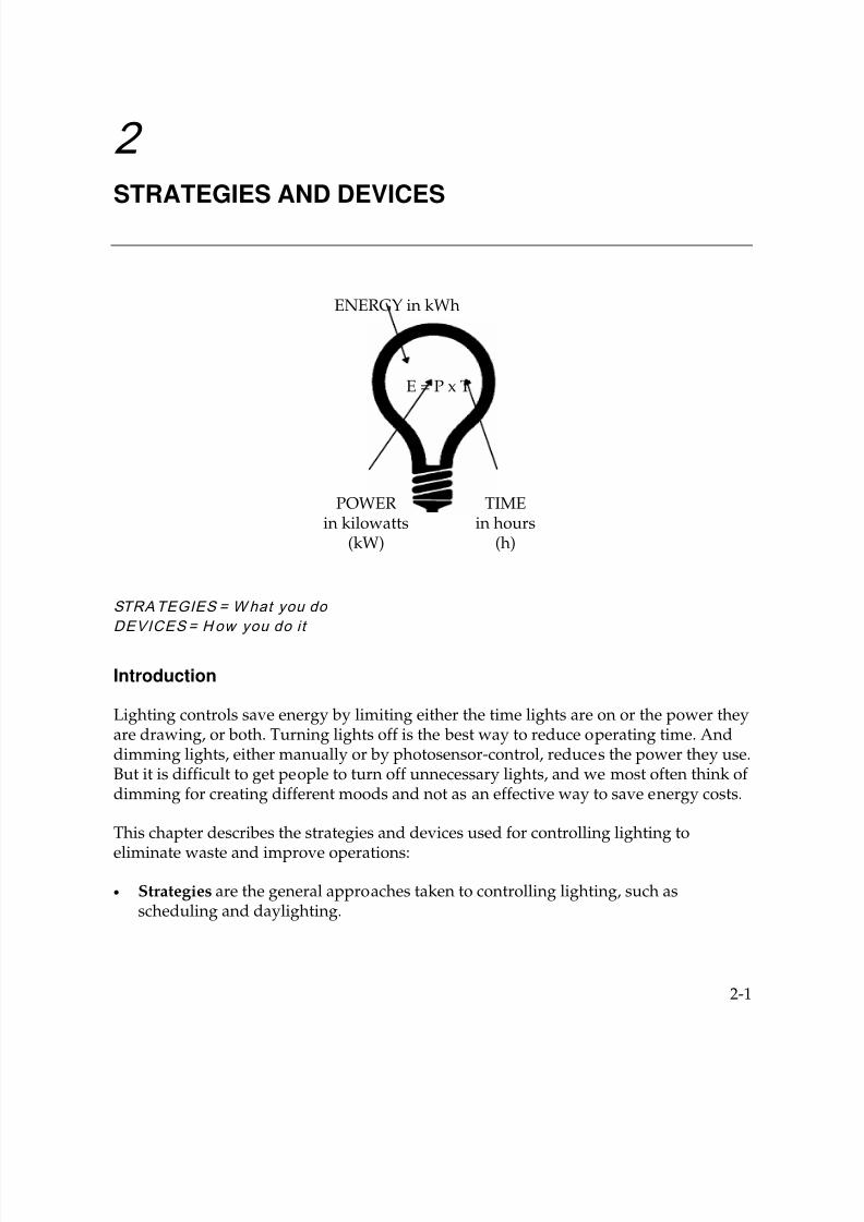
2STRATEGIES AND DEVICES
STRATEGIES = What you do
DEVICES = How you do it
Introduction
Lighting controls save energy by limiting either the time lights are on or the power theyare drawing, or both. Turning lights off is the best way to reduce operating time. Anddimming lights, either manually or by photosensor-control, reduces the power they use.But it is difficult to get people to turn off unnecessary lights, and we most often think of dimming for creating different moods and not as an effective way to save energy costs.
This chapter describes the strategies and devices used for controlling lighting toeliminate waste and improve operations:
• Strategies are the general approaches taken to controlling lighting, such asscheduling and daylighting.
ENERGY in kWh
POWERin kilowatts
(kW)
TIMEin hours
(h)
E = P x T
7/21/2019 Lighting Controls Patterns for Design
http://slidepdf.com/reader/full/lighting-controls-patterns-for-design 20/299
Strategies and Devices
2-2
• Devices are the specific pieces of equipment that are used to accomplish a strategy,such as occupancy sensors and photosensors.
Lighting control systems, which are interconnected devices that can include a centrallogic component such as a microcomputer, are also described.
Lighting Control Strategies
Strategies for saving lighting energy include:
• Occupancy responsive: Switching lights on when needed and off when not neededin response to unscheduled comings and goings of occupants.
• Timing: Switching lights on prearranged schedules.
•
Manual Dimming: Adjusting lights by hand (user controlled).
• Daylighting: Dimming or turning out lights automatically when daylight froma window or skylight provides sufficient light.
• Lumen-maintenance: Lowering light levels when lamps are new lumen outputis higher than needed. Then gradually increasing to full power at the low end of themaintenance cycle to maintain proper light levels.
• Tuning: Adjusting light levels to match occupants’ needs or desires (either by initialcalibration or by user).
• Adaptation Compensation: Reducing interior light levels when it’s dark outside,and increasing them when it’s bright outside, to reduce the range of light to whichthe human eye must adapt. Lower light levels at night are not only morecomfortable but usually safer because people’s eyes need not adapt as much(especially when moving from a lighter to a darker area). This strategy usuallyresults in energy savings.
• Load Shedding: Reducing lighting power at times of peak electrical demand.
The following table summarizes how these eight strategies save energy and how muchenergy they typically save. A symbol representing each strategy is shown in the left-hand column. These symbols are used in this chapter as an easy guide for readers tomatch strategies with devices.

7/21/2019 Lighting Controls Patterns for Design
http://slidepdf.com/reader/full/lighting-controls-patterns-for-design 21/299
Strategies and Devices
2-3
Strategy How It Saves Energy How Much It Can Save
OccupancyRespective
Switches lights on when neededand off when not needed
Depends on occupancypatterns, occupant energyawareness, etc.
Manual Requires the users to switch lights 10-50% (compared to noswitching)
Automatic Turns lights off and onautomatically
Up to 80% (compared to manualswitching)
Timing Turns lights on or off atpredetermined times, or turnslights off after a time delay
Depends on occupancypatterns; typically 10-50%(compared to manual switching)
Manual Dimming Allows user to set lights to lessthan full power
Depends on daylight availability,occupant energy awareness,etc.
Stepped Reduces lights levels by turningoff certain banks of lights
10-50%
Continuous
Dimming
Reduces power to all lights in asmooth continuum (requiresdimming ballasts)
10-50%
Daylighting Dims or extinguishing lights whenadequate daylight is present
Depends on how well daylightilluminates the space
On/Off Turns all lights off (most basicform of daylighting)
Up to 50% (compared to manualswitching)
Stepped Turns off banks of lights switchedtogether
Up to 70% (compared to manualswitching)
Continuous Dimming
Reduces power to all lights in asmooth continuum (requiresdimming ballasts)
Up to 80% under optimumconditions of good daylight andordinary hours of work
Lumen-maintenance
Dims lights (up to about 40%) justafter relamping and cleaning
10-20%
Tuning Sets lights to lowest usable level 10-50%, depending on howmuch over-lit and how wellmanaged
AdaptationCompensation
Reduces light levels at night or oncloudy days
Saves nighttime energy infacilities operating at night
Stepped Turns off banks of lights switchedtogether
10-40%
Continuous
Dimming
Reduces power to all lights in asmooth continuum (requiresdimming ballasts)
10-40%
Load Shedding Automatically dims lights slightlyor turns off unneeded lights atpeak demand times
Saves only a small amount ofenergy but a large amount ofdemand cost
7/21/2019 Lighting Controls Patterns for Design
http://slidepdf.com/reader/full/lighting-controls-patterns-for-design 22/299
Strategies and Devices
2-4
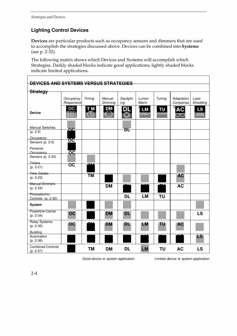
Lighting Control Devices
Devices are particular products such as occupancy sensors and dimmers that are usedto accomplish the strategies discussed above. Devices can be combined into Systems(see p. 2-32).
The following matrix shows which Devices and Systems will accomplish whichStrategies. Darkly shaded blocks indicate good applications; lightly shaded blocksindicate limited applications.
DEVICES AND SYSTEMS VERSUS STRATEGIES
Strategy
Occupancy Responsive
Timing Manual Dimming
Daylight- ing
Lumen Maint- enance
Tuning Adaptation Compensa -tion
Load Shedding
Device
Manual Switches(p. 2-5)
OccupancySensors (p. 2-5)
PersonalOccupancySensors (p. 2-20)
Timers(p. 2-21)
Time Clocks(p. 2-22)
Manual Dimmers(p. 2-24)
Photoelectric-Controls (p. 2-30)
System
Powerline-Carrier(p. 2-34)
Relay Systems(p. 2-35)
BuildingAutomation(p. 2-36)
Combined Controls(p. 2-37)
Good device or system application Limited device or system application
DLOC
OC
OC
TMOC
ACTM
ACTULMDLDM
TULMDL
LSDLDMTM
TM
OC
LS
ACTULMDLDMOC
ACTULMDLDMTMOC
OC LSACTULMDLDMTM

7/21/2019 Lighting Controls Patterns for Design
http://slidepdf.com/reader/full/lighting-controls-patterns-for-design 23/299
Strategies and Devices
2-5
Key to strategies
Good application
Limited application(See pages 2-2, 2-4 for key to symbols)
Manual Switches
Manual switches are the simplest control devices; they rely totally on people to manage
the use of lighting energy.
Standard Wall Switches
Most switches are standard toggle or the large paddle style, and most are rated15 or 20 amps(A) at 120 or 120/277 volts (V) AC. Because they are air-gap devices(have an opening between contacts),these switches can also server as safety-disconnectdevices for service and maintenance.
A latching switch is similar to a standard wall switch except that if power is interrupted
to a latching switch when it’s on, it automatically turns off. Latching switches are usedin “sweep” systems (p. 2-38).
Electronic or “Touch” Switches
The standard rating for touch switches is 1000 volt-amperes (VA) at 120 V. “Touch-ontouch-off” switches are electronic and the circuit is broken by an air gap. When thecircuit is “off,” a tiny amount of current still flows, posing a hazard for servicepersonnel. Most electronic switches include an air-gap disconnect for servicing.
Occupancy Sensors
Devices which switch lights on or off based on detection of motion within a specificroom or area are called “occupancy sensors.”

7/21/2019 Lighting Controls Patterns for Design
http://slidepdf.com/reader/full/lighting-controls-patterns-for-design 24/299
Strategies and Devices
2-6
There are three basic technologies used for detecting motion:
• Passive Infrared (PIR)
• Ultrasonic (ULT)
• Audible
Different sensor types use these technologies either singly or in combination, and eachtype of sensor has particular advantages and features that make it better suited tocertain applications. The table below shows the five typical sensor types, how theywork, and their basic advantages and disadvantages. Note that some types or featuresmay be proprietary and/or unique to one manufacture.
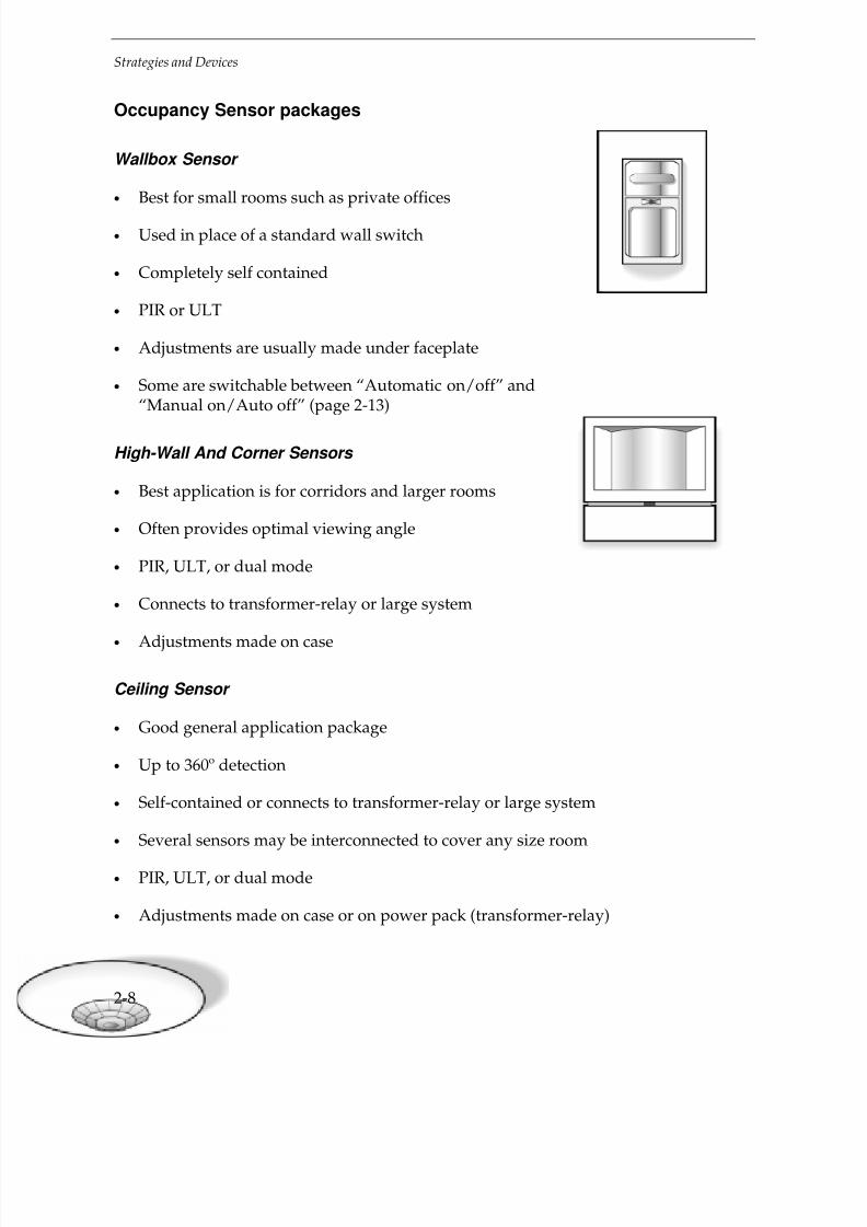
Packages
Occupancy sensors are available both as self-contained devices and as part of a control
system (p. 2-33), and come in four mounting packages: wallbox, ceiling, high-wall orcorner, and portable or “personal.” The main characteristics and best application foreach type are described on pages 2-8, 2-9.
Features
There are three special features available for occupancy sensors. Depending onmanufacturer and model, they may be standard, optional, or not available on aparticular unit. Below are descriptions of features and how they are applied.
Impending Shutoff (“Time-out”) Warning
What i t does: Flashes the lights or buzzes a few minutes before shutoff so occupant canmake motion to keep lights on.
Appli cati on Notes:
• Generally available on wall-mounted sensors only.
• The signal may annoy neighbors and may bring unwanted attention to the control.
• Audible signal can’t be heard by the hearing impaired.
StandardToggle
Touch onTouch off
Air-GapDisconnect
Decora StylePaddleSwitch

7/21/2019 Lighting Controls Patterns for Design
http://slidepdf.com/reader/full/lighting-controls-patterns-for-design 25/299
Strategies and Devices
2-7
Occupancy Sensor Technologies
Sensor type How it works Advantages Disadvantages
Passive Infrared
(PIR)
Detects body heatcrossing a detectionzone. Lens designdetermines area ofdetection.
• Fairly immune to“false-ons” frommotion in
adjacent spaces.• Good in spaces
where a cut-off(non-sensed)area is required.
• Effective even athigher mountingheights, e.g., 20’.
• “Line-of-sight”required todetect motion
(more so thanfor ultrasonic).
Thus, beware ofodd-shapedrooms,vestibules,columns, andpartitions.
Ultrasonic (ULT) Emits ultrasound.Frequency shift inreflected signalsignifies motion.
• Better than PIR atdetecting motionwhen line-of-sightis interrupted;
good in odd-shaped roomsand rooms withobstructions(vestibules,columns, etc.).
• Can be moresensitive to smallmotions than PIR.
• May be moresensitive to“false-ons” fromadjacent spaces,
air turbulence, orobjects hangingin space thanPIR.
• Has lesssensitivity in highspaces (whenmounted over12-14’).
Dual Technology
PIR/ULT
Typically set torequire both infraredand ultrasonic
detections to turnlights on initially, andeither form ofdetection to keepthem on.
• Effective in mostspaces.
• Minimizes “false-
ons” (needs twosignals).
• Minimizes “false-offs” (takes eithersignal—can besensitive tosmallermovements).
• More expensivethan singletechnologies.
• Can be kept onby motion inadjacent spaces.
Audible
(microphonics)
Detects leading-edgenoise only, ignoringconstant noise.
• Simple andinexpensive (oldtechnology).
• Very sensitive to“false-ons.”
• Could be kept onby noise from
adjacent space.Audible with PIR or
ULT
PIR turns lights on;either keeps them on.
• Similaradvantages toDual Technologyabove, thoughmore suitable forspaces separatedfrom nearby noise.
• Usually moreexpensive thansingletechnologies.
• Could be kept onby noise fromadjacent space.
PassiveInfraredSensor
Ultrasonic
Sensor
Detectionzones
Inaudible
waves
7/21/2019 Lighting Controls Patterns for Design
http://slidepdf.com/reader/full/lighting-controls-patterns-for-design 26/299
Strategies and Devices
2-8
Occupancy Sensor packages
Wallbox Sensor
• Best for small rooms such as private offices
• Used in place of a standard wall switch
• Completely self contained
• PIR or ULT
• Adjustments are usually made under faceplate
• Some are switchable between “Automatic on/off” and“Manual on/Auto off” (page 2-13)
High-Wall And Corner Sensors
• Best application is for corridors and larger rooms
• Often provides optimal viewing angle
• PIR, ULT, or dual mode
• Connects to transformer-relay or large system
• Adjustments made on case
Ceiling Sensor
• Good general application package
• Up to 360º detection
• Self-contained or connects to transformer-relay or large system
• Several sensors may be interconnected to cover any size room
• PIR, ULT, or dual mode
• Adjustments made on case or on power pack (transformer-relay)
7/21/2019 Lighting Controls Patterns for Design
http://slidepdf.com/reader/full/lighting-controls-patterns-for-design 27/299
Strategies and Devices
2-9
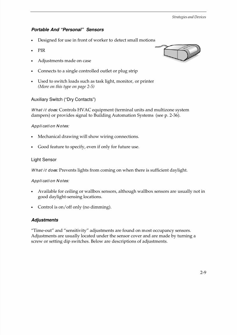
Portable And “Personal” Sensors
• Designed for use in front of worker to detect small motions
• PIR
• Adjustments made on case
• Connects to a single controlled outlet or plug strip
• Used to switch loads such as task light, monitor, or printer(More on this type on page 2-5)
Auxiliary Switch (“Dry Contacts”)
What i t does: Controls HVAC equipment (terminal units and multizone system
dampers) or provides signal to Building Automation Systems (see p. 2-36).
Appli cati on Notes:
• Mechanical drawing will show wiring connections.
• Good feature to specify, even if only for future use.
Light Sensor
What i t does: Prevents lights from coming on when there is sufficient daylight.
Appli cati on Notes:
• Available for ceiling or wallbox sensors, although wallbox sensors are usually not ingood daylight-sensing locations.
• Control is on/off only (no dimming).
Adjustments
“Time-out” and “sensitivity” adjustments are found on most occupancy sensors.Adjustments are usually located under the sensor cover and are made by turning ascrew or setting dip switches. Below are descriptions of adjustments.

7/21/2019 Lighting Controls Patterns for Design
http://slidepdf.com/reader/full/lighting-controls-patterns-for-design 28/299
Strategies and Devices
2-10
Time-out (Time delay)
What i t A djusts: How long lights stay on after last motion is detected. Any new motionresets and restarts time-out.
Appli cati on Notes:
• Most devices can be adjusted anywhere from 30 seconds to 20 minutes(or longer).
• Settings under 5 or 10 minutes save the most energy but may cause “false-offs”depending on activity level.
• Longer settings minimize lamp cycling.
Sensitivity
What i t A djusts: How small a motion is detected and how large an area is covered.
Appli cati on Notes:
• Especially important for ultrasonic and dual-mode sensors to minimize“false-ons” and “false-offs.”
• PIR devices may not have a sensitivity adjustment but their coverage area canusually be modified with masking strips or built-in shutters on the lens.
Features and adjustments that are desirable for specific space types are shown inChapter 5, Design Patterns.
Power Packs
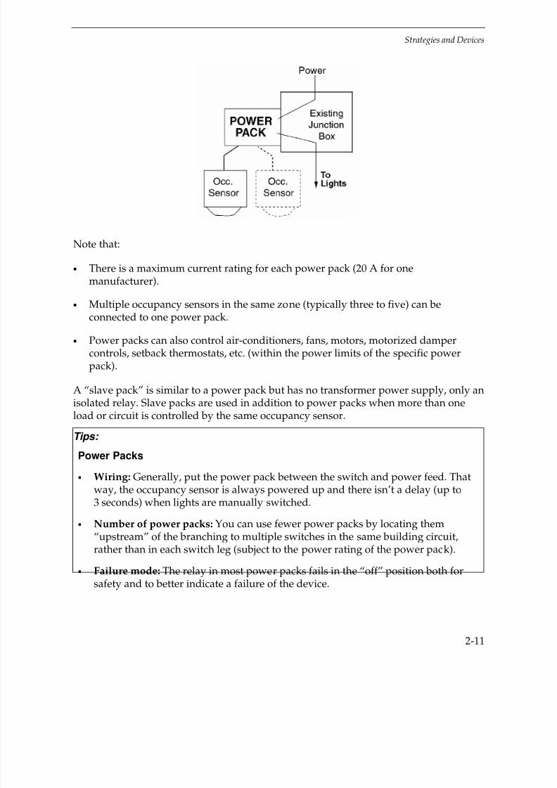
“Power packs” are transformer-relays used to:
• Generate low-voltage power for the occupancy sensor
• Switch the line-voltage power to the lights on a signal from the sensor.
Power packs, also called switch packs, are generally required with non-wallbox sensorsand are sold separately by occupancy sensor vendors. They usually mount in or on junction boxes.
7/21/2019 Lighting Controls Patterns for Design
http://slidepdf.com/reader/full/lighting-controls-patterns-for-design 29/299
Strategies and Devices
2-11
Note that:
• There is a maximum current rating for each power pack (20 A for onemanufacturer).
• Multiple occupancy sensors in the same zone (typically three to five) can beconnected to one power pack.
• Power packs can also control air-conditioners, fans, motors, motorized dampercontrols, setback thermostats, etc. (within the power limits of the specific powerpack).
A “slave pack” is similar to a power pack but has no transformer power supply, only an
isolated relay. Slave packs are used in addition to power packs when more than oneload or circuit is controlled by the same occupancy sensor.
Tips:
Power Packs
• Wiring: Generally, put the power pack between the switch and power feed. Thatway, the occupancy sensor is always powered up and there isn’t a delay (up to3 seconds) when lights are manually switched.
• Number of power packs: You can use fewer power packs by locating them
“upstream” of the branching to multiple switches in the same building circuit,rather than in each switch leg (subject to the power rating of the power pack).
• Failure mode: The relay in most power packs fails in the “off” position both forsafety and to better indicate a failure of the device.

7/21/2019 Lighting Controls Patterns for Design
http://slidepdf.com/reader/full/lighting-controls-patterns-for-design 30/299
Strategies and Devices
2-12
High-low Control
High-low control is used to dim fluorescent or HID lighting to a low level instead of turning the lights off when people aren’t present. This type of control is useful in spaceswith frequent use of short duration (e.g., corridors, library stack areas, and warehouse
aisles). When the space is occupied, the lights are on full, but shortly after the space isvacated the lights are dimmed to a preset level, usually 10-20% light output.
For fluorescent lamps, high-low control reduces lamp cycling and increases lamp life(see page 2-19). For HID lamps, the issue is restrike time: changing from 20% to100% light output takes only a few seconds, but when restarting from off, HID lampstake 2-5 minutes or more to reach full light output.
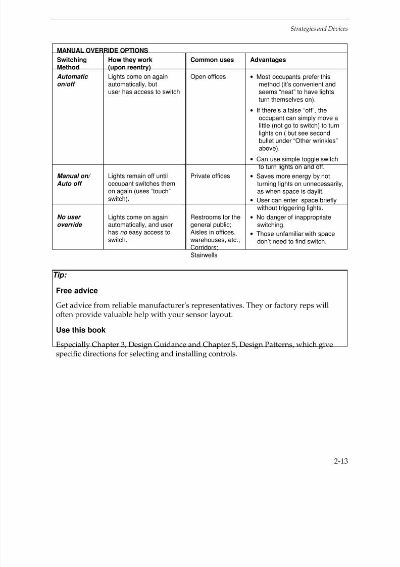
Manual override options
Lights controlled by an occupancy sensor are usually manually switched as well.Common switching methods are “Automatic on/off,” “Manual on/Auto off” and“No user override.” These switching methods are explained in the table below.
Note that with “No user override” the occupant can’t turn off lights when leaving,which keeps lights on during the time delay period. This wastes energy, especially withswitch-conscious occupants and/or with frequent on-offs (see sidebar “Let ‘emswitch”).
Other wrinkles include:
• With either “Automatic on/off” or “Manual on/Auto off” switching, the user canalso switch lights off manually if necessary (e.g., to darken the room for anaudio-visual presentation or when there is sufficient daylight).
• Some sensors with “Manual on/Auto off” switching will reactivate lightsautomatically if motion is made within a short period of “turn-off” by the sensor(so a sedentary occupant doesn’t have to get up to turn lights back on).
• On occupancy sensors with built-in switches (e.g., wallbox sensors), the manualswitching method is either preset or “settable” on the unit. If settable on the unit,the designer should show on the drawing which setting to use. For all otheroccupancy sensors, you design the switching method; product literature hasexamples.
• Some units have an internal setting for an “on” position that overrides theoccupancy sensor. Note that easy user access to this override “on” position isprohibited by some state energy codes (e.g., California’s Title 24).
7/21/2019 Lighting Controls Patterns for Design
http://slidepdf.com/reader/full/lighting-controls-patterns-for-design 31/299
Strategies and Devices
2-13
MANUAL OVERRIDE OPTIONS
SwitchingMethod
How they work(upon reentry)
Common uses Advantages
Automatic on/off
Lights come on againautomatically, butuser has access to switch
Open offices • Most occupants prefer thismethod (it’s convenient andseems “neat” to have lightsturn themselves on).
• If there’s a false “off”, theoccupant can simply move alittle (not go to switch) to turnlights on ( but see secondbullet under “Other wrinkles”above).
• Can use simple toggle switchto turn lights on and off.
Manual on/
Auto off
Lights remain off untiloccupant switches them
on again (uses “touch”switch).
Private offices • Saves more energy by notturning lights on unnecessarily,
as when space is daylit.• User can enter space briefly
without triggering lights.
No user
override Lights come on againautomatically, and userhas no easy access toswitch.
Restrooms for thegeneral public;Aisles in offices,warehouses, etc.;Corridors;Stairwells
• No danger of inappropriateswitching.
• Those unfamiliar with spacedon’t need to find switch.
Tip:
Free advice
Get advice from reliable manufacturer's representatives. They or factory reps willoften provide valuable help with your sensor layout.
Use this book
Especially Chapter 3, Design Guidance and Chapter 5, Design Patterns, which givespecific directions for selecting and installing controls.

7/21/2019 Lighting Controls Patterns for Design
http://slidepdf.com/reader/full/lighting-controls-patterns-for-design 32/299
Strategies and Devices
2-14
Tip:
Let’ em switch
In a restroom with a dual technology occupancy sensor (PIR and audible detection)
at Tacoma City Light offices, the lights were monitored for 40 days (minimum) undereach of three control conditions:
Having a switch and sensor (Automatic on/off) saved 70% more than the sensor alone(No user override). By switching lights off when leaving, users can eliminate lights-onduring the sensor's time delay period (6 minutes). Thirty people a day used therestroom.
OCCUPANCY SENSOR
In Chapter 5, Design Patterns, manual override options are recommended for specificspace types.

7/21/2019 Lighting Controls Patterns for Design
http://slidepdf.com/reader/full/lighting-controls-patterns-for-design 33/299
Strategies and Devices
2-15
Design considerations
1. Suitability: Choose a sensor whose coverage area matches the size and shape of theroom.
•
For example, a round PIR pattern may happen to “match” a square room betterthan a rectangular ultrasonic pattern (see figure). Check the manufacturer’ssensor coverage template, diagram, or specifications.
Match pattern to room:
• Consider wallbox sensors for small rooms; ceiling and high-wall sensors for allother spaces.
• If a catalogue shows different sensor coverages for “walking” and “small hand
motion,” use the small-motion coverage unless you know there will be majormotion, as in a corridor or gymnasium.
2. Furnishings: Take furniture and other objects in the room into account.
For example:
• If partitions are present, locate ceiling sensors to avoid creating dead spots intheir “shadows.”
• Don’t locate wallbox sensors where their view may be partly blocked by an opendoor, cabinet, or bookcase.
• Soft or porous room surfaces may reduce the coverage of ultrasonic sensors. Seeproduct literature.
3. Switching method: Choose “Manual on/Auto off” to encourage maximum energysavings, but “No user override” in hallways, rest rooms for the general public, etc.as a convenience.
7/21/2019 Lighting Controls Patterns for Design
http://slidepdf.com/reader/full/lighting-controls-patterns-for-design 34/299
Strategies and Devices
2-16
Risks
Described below are specific risks to avoid when applying occupancy sensors: False“Off,” Dead Spots, False “On,” Short Lamp Life, Under-Loading, Inrush, andElectromagnetic Interference (EMI).
False “O ff.” Sensors can turn off lights even when there are people present and there isnormal motion. For instance, a wallbox sensor might not pick up a person typing at akeyboard with their back to the sensor .
The causes for false “offs” are:
• Sensor sensitivity adjustment set too low
• Sensor time delay set too short
• Infrared sensor’s “eyes” pointing in the wrong direction
• Infrared sensor’s line-of-sight blocked
• Ultrasonic sensor with wrong detection pattern or installed in wrong orientation
Dead Spot s. Because neither the installer nor designer can actually “see” the detectionzone of the device, it is possible to have dead zones where automatic devices likemotion sensors don’t work. Usually, the problem is one of the following:
• The product is not installed and/or adjusted according to the manufacturer’s
recommendations.
• The designer tried to make a sensor cover it’s maximum rated range or just a little bit more...
• Occasionally, a sensor with a rectangular pattern is installed 90º off (Murphy’s law).Put a note on the drawing: “Install sensor so that long sensing dimension is indirection of arrows on drawing.”
• The designer forgot there would be furnishings obstructing the sensor’s view, or theuser brought in partitions, etc. later.
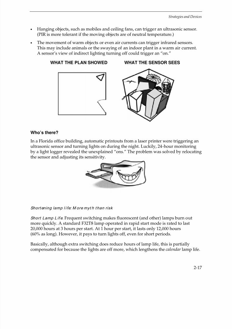
False “O n.” Occupancy sensors can be fooled into turning lights on when there is noone in the room. While this is less common with modern sensors, it may occur in thefollowing situations:
• Motion in an adjacent room can trigger an ultrasonic (and possibly a PIR) sensor,especially if it’s located so it “sees” into a hallway or other busy place.
7/21/2019 Lighting Controls Patterns for Design
http://slidepdf.com/reader/full/lighting-controls-patterns-for-design 35/299
Strategies and Devices
2-17
• Hanging objects, such as mobiles and ceiling fans, can trigger an ultrasonic sensor.(PIR is more tolerant if the moving objects are of neutral temperature.)
• The movement of warm objects or even air currents can trigger infrared sensors.This may include animals or the swaying of an indoor plant in a warm air current.A sensor’s view of indirect lighting turning off could trigger an “on.”
WHAT THE PLAN SHOWED WHAT THE SENSOR SEES
Who’s there?
In a Florida office building, automatic printouts from a laser printer were triggering anultrasonic sensor and turning lights on during the night. Luckily, 24-hour monitoring by a light logger revealed the unexplained “ons.” The problem was solved by relocatingthe sensor and adjusting its sensitivity.
Short ening lamp l i fe: M ore myt h t han risk
Short Lamp L if e. Frequent switching makes fluorescent (and other) lamps burn out
more quickly. A standard F32T8 lamp operated in rapid start mode is rated to last20,000 hours at 3 hours per start. At 1 hour per start, it lasts only 12,000 hours(60% as long). However, it pays to turn lights off, even for short periods.
Basically, although extra switching does reduce hours of lamp life, this is partiallycompensated for because the lights are off more, which lengthens the calendar lamp life.

7/21/2019 Lighting Controls Patterns for Design
http://slidepdf.com/reader/full/lighting-controls-patterns-for-design 36/299
Strategies and Devices
2-18
SWITCHING EFFECTS
And, more important, the increased energy savings far outweigh the added relampingcosts as switching frequency increases. As the graph below shows, even when lightingis switched on and off an average of twice per hour (20 times over 10 hours) to keeplight off half the time, the annual energy savings is approximately 7 times greater thanthe average annual relamp cost compared to the base case.
Assumptions:
Fixture: 2-lamp, T8, rapid start = 62W
Base case operation: = 2,500 hr/yr.10 hr/day, 250day/yr
Rated lamp life (@ 3 hr/start) = 20,000 hr
Electric Rate = $0.08/kWh(including demand)
Relamp Cost = $8/fixture(labor + materials)
Net HVAC savings multiplier = 1.15(for New York City)
See Appendix C, Economics (p. C-1), for complete data and assumptions.
The risk in frequent switching by an occupancy sensor is not economic but that “falseoffs” will likely occur if time delay settings are too short. Time delay settings under10 minutes are not recommended for most applications.

7/21/2019 Lighting Controls Patterns for Design
http://slidepdf.com/reader/full/lighting-controls-patterns-for-design 37/299
Strategies and Devices
2-19
Tip:
Factors in Lamp Life
Recent research indicates that the effect of switching frequency on lamp life dependson the length of the “on” periods and the type of lamp:
• For very short “on” periods (under 15 minutes): Instant start lamps may havelonger life than rapid start, apparently because the cathode doesn’t have time tocool off (during the short “off” periods).
• For medium length “on” periods: Rapid start lamps have a longer life than instantstart.
• For long “on” periods (several hours): Either type lamp will perform well.
Under-Loading. Some sensors have high minimum-load requirements. Most low-costsensors use electronic “switches” rather than relay contacts to switch lights. Theoperating power for these sensors come from the circuit that connects the load theycontrol. If the load is tool small, insufficient operating power causes the sensor to workerratically. To compound the problem, the minimum load requirement specified for thesensor is generally the load needed for the sensor to work with either a resistive(incandescent) or inductive (magnetic) load. The minimum load requirement for usewith electronic ballast loads may be much higher.
• Almost all “two-wire” (no neutral connection) sensors are this type. Althougheasiest to install in existing circuits, two-wire devices are best limited to non-
electronic loads.• Three-wire sensors (hot-switched-neutral) are generally more tolerant of small
loads, and even the electronically-switched type require only a small load to workproperly.
Current vs. Time

7/21/2019 Lighting Controls Patterns for Design
http://slidepdf.com/reader/full/lighting-controls-patterns-for-design 38/299
Strategies and Devices
2-20
Inrush. All lighting loads have current inrush. For example, incandescent lampstypically demonstrate 10-15 times rated current for the first few cycles as the filamentwarms to operating temperature. Most devices are rated to withstand current inrush; but, under some conditions with electronic ballasts, inrush may be as high as 100 timerated current for part of a cycle. Before specifying combinations of ballasts and
occupancy sensors, make certain the device is rated for the inrush to the ballast underworst-case conditions.
Notes:
1. The highest inrush ballasts generally have the most rapid start (so there’s some goodwith the bad).
2. “Zero-crossing” devices, which switch the load when the alternating current is nearzero, can better tolerate current spikes.
Elect romagnet i c I nt erference (EM I ). Infrared and ultrasonic sensors only emit EMI
when switching, just like any other switching device.
Ultrasonic sensors may interfere with the operation of some hearing aids, which mayinhibit their use in health-care, elderly housing, and certain educational facilities. Theproblem seems to occur with ultrasonic sensors that use lower frequencies (under30 kHz); in these applications use higher frequency (e.g., 32 kHz) models, which areusually available instead. Also, hearing aid makers sometimes filter out these potentialproblem frequencies.
Key to strategies
Good application
Limited application
(See page 2-3, 2-4 for key to symbols)
Personal Occupancy Sensors
This type of motion sensor is used for office workstations and similar applications. Thesensor is connected to a single outlet or plug strip to control plug-in electric loads suchas task lights, computer peripherals, and space heaters (if within the power strip rating).
7/21/2019 Lighting Controls Patterns for Design
http://slidepdf.com/reader/full/lighting-controls-patterns-for-design 39/299
Strategies and Devices
2-21
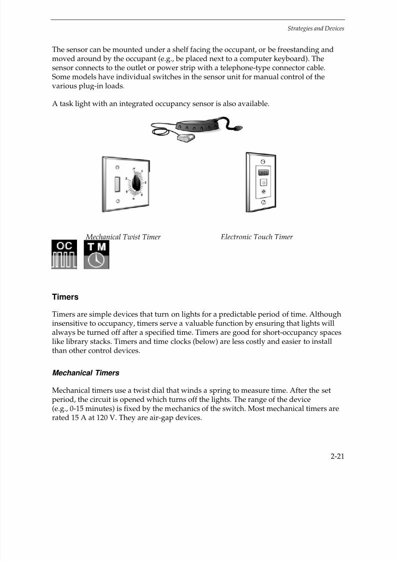
The sensor can be mounted under a shelf facing the occupant, or be freestanding andmoved around by the occupant (e.g., be placed next to a computer keyboard). Thesensor connects to the outlet or power strip with a telephone-type connector cable.Some models have individual switches in the sensor unit for manual control of thevarious plug-in loads.
A task light with an integrated occupancy sensor is also available.
Mechanical Twist Timer Electronic Touch Timer
Timers
Timers are simple devices that turn on lights for a predictable period of time. Althoughinsensitive to occupancy, timers serve a valuable function by ensuring that lights willalways be turned off after a specified time. Timers are good for short-occupancy spaceslike library stacks. Timers and time clocks (below) are less costly and easier to installthan other control devices.
Mechanical Timers
Mechanical timers use a twist dial that winds a spring to measure time. After the setperiod, the circuit is opened which turns off the lights. The range of the device(e.g., 0-15 minutes) is fixed by the mechanics of the switch. Most mechanical timers arerated 15 A at 120 V. They are air-gap devices.

7/21/2019 Lighting Controls Patterns for Design
http://slidepdf.com/reader/full/lighting-controls-patterns-for-design 40/299
Strategies and Devices
2-22
Electronic Timers
Electronic timers generally have a touch control to set the time lights should go off andan optional “time-out” warning. Some electronic timers are not air-gap devices.
Risks
Most timers are simple and dependable. However, mechanical timers are occasionallynoisy or their construction not durable enough. Electronic timers are usually the betterchoice.
Time Clocks
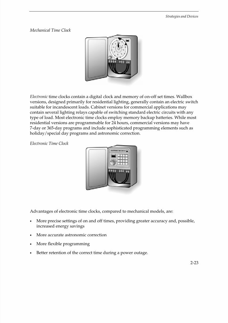
The redundant expression “time clock” has been used for decades to describe electricclocks that have a mechanical dial with trippers attached to open or close an air-gapswitch at set times.
More recently, electronic devices have become popular as well.
Mechanical time clocks have an integral 120 V motor-operated clock. They are availableas portable plug-in devices as well as wallbox-mounted devices. Larger devices areenclosed in interior and exterior NEMA boxes, and they generally control two 40 Acircuits. Smaller devices are usually 24-hour-schedule devices. Larger units can also
include such features as 7-day calendar clocks, spring-driven time retention, and“astronomical” dials, which are (theoretically) able to compensate for the change of seasons.
Tip:
Astronomic Corre ction
This is the automatic correction of the time clock’s on and off set times to account forvarying sunrise and sunset time during the year. Latitude is an input.
7/21/2019 Lighting Controls Patterns for Design
http://slidepdf.com/reader/full/lighting-controls-patterns-for-design 41/299
Strategies and Devices
2-23
Mechanical Time Clock
Electronic time clocks contain a digital clock and memory of on-off set times. Wallboxversions, designed primarily for residential lighting, generally contain an electric switchsuitable for incandescent loads. Cabinet versions for commercial applications maycontain several lighting relays capable of switching standard electric circuits with anytype of load. Most electronic time clocks employ memory backup batteries. While mostresidential versions are programmable for 24 hours, commercial versions may have7-day or 365-day programs and include sophisticated programming elements such asholiday/special day programs and astronomic correction.
Electronic Time Clock
Advantages of electronic time clocks, compared to mechanical models, are:
• More precise settings of on and off times, providing greater accuracy and, possible,increased energy savings
• More accurate astronomic correction
• More flexible programming
• Better retention of the correct time during a power outage.
7/21/2019 Lighting Controls Patterns for Design
http://slidepdf.com/reader/full/lighting-controls-patterns-for-design 42/299
Strategies and Devices
2-24
Risks
Most time schedule switching devices and systems are relatively simple and reliable;however, there are three common problems:
• Where is the darn thing?? Time clocks may be located out of the way in a closet ormechanical room. Finding them to revise or correct settings can be challenging.Clearly label the location of time clocks and similar controls.
• Where are the darn instructions?? Specify that the instructions be placed in a durableprotector, properly marked, and attached in reach of the device.
• Programmability. The less expensive the device or system, the “dumber” it is (thoughmaybe easier to understand). For example, simple time clocks can’t be programmedto distinguish holidays from regular workdays so lights might be “on unnecessarilyon holidays. Smart systems, on the other hand, can be fully programmed but they
are harder to understand and more difficult to reprogram when changes need to bemade.
Tip:
Job Security:
Having the only copy of instructions for setting the time clock.
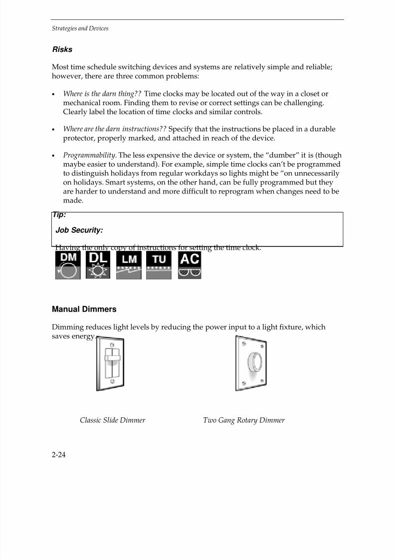
Manual Dimmers
Dimming reduces light levels by reducing the power input to a light fixture, whichsaves energy.
Classic Slide Dimmer Two Gang Rotary Dimmer
7/21/2019 Lighting Controls Patterns for Design
http://slidepdf.com/reader/full/lighting-controls-patterns-for-design 43/299
Strategies and Devices
2-25
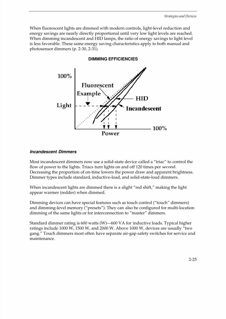
When fluorescent lights are dimmed with modern controls, light-level reduction andenergy savings are nearly directly proportional until very low light levels are reached.When dimming incandescent and HID lamps, the ratio of energy savings to light levelis less favorable. These same energy saving characteristics apply to both manual andphotosensor dimmers (p. 2-30, 2-31).
DIMMING EFFICIENCIES
Incandescent Dimmers
Most incandescent dimmers now use a solid-state device called a “triac” to control theflow of power to the lights. Triacs turn lights on and off 120 times per second.Decreasing the proportion of on-time lowers the power draw and apparent brightness.Dimmer types include standard, inductive-load, and solid-state-load dimmers.
When incandescent lights are dimmed there is a slight “red shift,” making the lightappear warmer (redder) when dimmed.
Dimming devices can have special features such as touch control (“touch” dimmers)and dimming-level memory (“presets”). They can also be configured for multi-locationdimming of the same lights or for interconnection to “master” dimmers.
Standard dimmer rating is 600 watts (W)—600 VA for inductive loads. Typical higherratings include 1000 W, 1500 W, and 2000 W. Above 1000 W, devices are usually “twogang.” Touch dimmers most often have separate air-gap safety switches for service andmaintenance.
7/21/2019 Lighting Controls Patterns for Design
http://slidepdf.com/reader/full/lighting-controls-patterns-for-design 44/299
Strategies and Devices
2-26
Tip:
Scene Controls Can Save Energy
Scene controls permit multiple memorized dimmer settings to be activated by
pressing one button. A “cross fade” from the previous setting makes for smoothtransitions. The duration of the cross-fade can even be programmed to make thetransition seamless. The most common configuration is a “four-scene” controller inwhich four sets of memorized dimmer settings, or “scenes,” can be recalled bypressing one of four buttons. (There is usually a fifth “off” button and sometimes asixth “all on” button.)
While usually intended for manual activation in architectural or theatrical settings,scene controls can be designed to allow energy-oriented activation, such as byphotosensor input. In this way, spaces with complex lighting systems like finerestaurants and themed facilities can save energy without sacrificing the flexibility
and ease of control inherent in scene dimming.
If you’re going to have scene controls consider also booking them up to occupancysensors, photosensors, etc., to save energy.
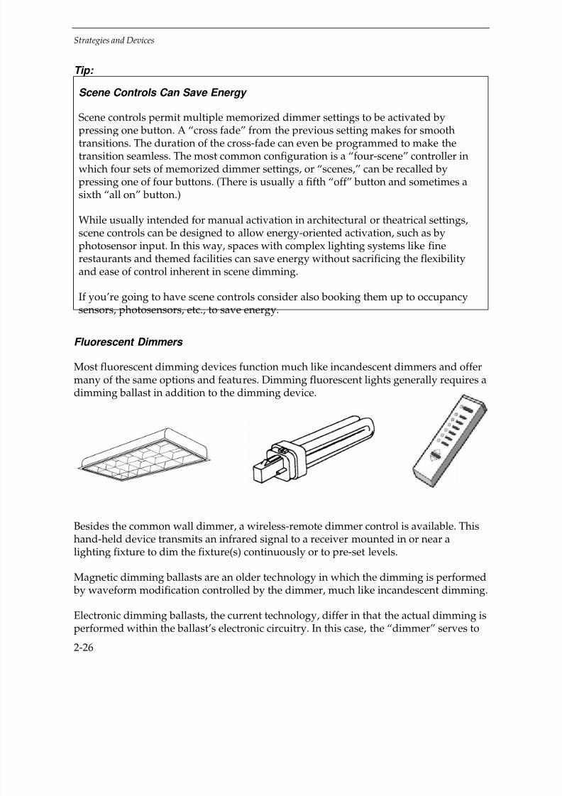
Fluorescent Dimmers
Most fluorescent dimming devices function much like incandescent dimmers and offermany of the same options and features. Dimming fluorescent lights generally requires adimming ballast in addition to the dimming device.
Besides the common wall dimmer, a wireless-remote dimmer control is available. This
hand-held device transmits an infrared signal to a receiver mounted in or near alighting fixture to dim the fixture(s) continuously or to pre-set levels.
Magnetic dimming ballasts are an older technology in which the dimming is performed by waveform modification controlled by the dimmer, much like incandescent dimming.
Electronic dimming ballasts, the current technology, differ in that the actual dimming isperformed within the ballast’s electronic circuitry. In this case, the “dimmer” serves to

7/21/2019 Lighting Controls Patterns for Design
http://slidepdf.com/reader/full/lighting-controls-patterns-for-design 45/299
Strategies and Devices
2-27
generate a control signal to the ballast, rather than actually dimming the lamp. Thereare four primary types of control signals:
• A 0-10 VDC signal which linearly corresponds to the light output desired from the ballast (0 V = 0 light, 10 V = 100% light). Four wires (hot, neutral, and two signal)
connect to the ballast. This is the most common control signal used by majorelectronic ballast markets.
• A phase-angle power signal used with standard magnetic dimming ballast circuits.Three wires (hot, hotdimmed, and neutral) connect to the ballast. This method,while less popular, allows easy retrofit of existing dimming ballasts.
• A phase-angle power signal for use with existing standard incandescent phase-anglecircuits. Only two wires (hot-dimmed and neutral) connect to the ballast. This circuitis especially useful in retrofit situations where dimming is being added, or can beused where dimmable fluorescent lamps are replacing dimmable incandescent
lamps. Note that some ballasts may require specific incandescent dimmers.
• A specific signal for use with proprietary control circuits. This signal may be analogor digital and may be part of a comprehensive communications and control system.Ballasts are generally connected by the power wires (hot and neutral) plus thewiring required by the communications system.
Most electronic dimming ballasts will operate lamp properly from 100% output downto about 20%. To achieve lighting levels below 20%, ballasts need to be more complexand costly. Those capable of achieving stable light levels less than 10% output and aslow as 0.5% are generally more expensive and are primarily used for architecturaldimming applications.
HID Dimmers
HID lamps require special dimming devices and ballasts. The dimming range isgenerally 100% to about 20%. Due to the long warmup and restrike times, and otheroperating concerns of HID lamps, there may be a time delay as dimming occurs. Andcertain lamp characteristics, especially color, will change, so HID dimming is best usedfor industrial situations where color is not particularly important.

7/21/2019 Lighting Controls Patterns for Design
http://slidepdf.com/reader/full/lighting-controls-patterns-for-design 46/299
Strategies and Devices
2-28
Risks
While manual dimmers have become commonplace, there are still risks:
• Low cost “hardware store” dimmers should only be used with incandescent lamps;
they will not dim fluorescent lamps properly.
• To dim low-voltage incandescent lamps, you must use the correct dimmer. Dimmersare applied on the transformer primary and there are different types for magneticand electronic transformers. Using the wrong dimmer can damage equipment.
• Fluorescent lamps should be dimmed using a dimming ballast and properly rateddimmer. Although an incandescent dimmer will appear to work with a magnetic ballast and fluorescent lamp, low-end performance will be poor and lamp lifeshortened.
• HID lamps can be dimmed with properly rated dimmers and ballasts but beprepared for undesirable color shift.
Photoelectric Controls
Photoelectric controls include photoswitches and photosensors.
Photoswitches and Photosensors
There are two principal types of photoelectric controls:
• “Photosw i t ches ” are devices that turn lights on or off according to the amount of light striking the sensor (photocell) surface. Most photoswitches are designed forswitching outdoor lighting at dawn and dusk. Exterior photoswitches are notadjustable.
Because most people object to abrupt on-off switching of lights where they work,interior applications of photoswitches are somewhat limited. All photoswitches aredesigned for open-loop applications (see next page), so they must be located so asnot to sense the light from the fixtures they control.

7/21/2019 Lighting Controls Patterns for Design
http://slidepdf.com/reader/full/lighting-controls-patterns-for-design 47/299
Strategies and Devices
2-29
Key to strategies
Good application
Limited application
(See page 2-3 for key to symbols)
OPEN-LOOP
CLOSED-LOOP
PHOTOSWITCHVERSUS PHOTOSSENSOR

7/21/2019 Lighting Controls Patterns for Design
http://slidepdf.com/reader/full/lighting-controls-patterns-for-design 48/299
Strategies and Devices
2-30
• “Photosensors ” can continuously vary light output, usually by controllingfluorescent dimming electronic ballasts. They dim lights for daylighting and, if in aclosed loop system (see below), for tuning and lumen-maintenance. Mostphotosensors have adjustments similar to occupancy sensors, including time delay,response speed, and sensitivity.
Photosensors and ballasts may be purchased separately or as a single vendorsystem. Some systems include manual dimmers, occupancy sensors, and/orconnections to building-wide monitoring or load shedding. A local master controller(page 2-45) facilitates the integration of such diverse strategies. See CombinedControls (page 2-37).
Compared to occupancy sensors, photosensor development and acceptance is about7-10 years behind; but they are catching up, and soon should be nearly as easy toapply and use as occupancy sensors.
Dimming technologies are described in Manual Dimmers (page 2-24).
Open- versus Closed-Loop Photocontrols
In an “open-loop” system, a remotely located photosenses sensors the amount of daylight. The sensor may be outside the building or in another room or zone. It thenadjusts electric light output to compensate for available daylight and maintain apredetermined light level. In an open-loop system, one photosensor can control anynumber of lights.
In a “closed-loop” system, the photosensor is located in the space it controls; and, in thiscase, it senses the sum of electric light and, if present, daylight, and then adjusts thelights to maintain the desired light level. In this system, the photosensor can onlycontrol a limited number of lights (only those lights that affect its field of view).
Open-loop uses remote control; closed-loop uses direct feedback.

7/21/2019 Lighting Controls Patterns for Design
http://slidepdf.com/reader/full/lighting-controls-patterns-for-design 49/299
Strategies and Devices
2-31
Most lighting controls for small rooms, such as offices or classrooms, are closed-loopsystems. When properly adjusted, these systems compensate both for daylight(including windows, skylights, and the effect of curtains or blinds) and lumen-maintenance, and in addition, the light level can usually be tuned to the user’s needs.Lighting controls for larger areas, such as factories and airports, are usually best
designed using open-loop systems.
Tip:
Remember On-Off
A photosensor is not an on-off control. You still need a manual switch and, if possible,an automatic on-off device such as a time clock or occupancy sensor.
Risks
Most dimming components are not interchangeable, and different technologies performdifferently. For example, generic photosensors are designed to generate a 0-10 voltsignal and generic dimming ballasts are designed to operate from this signal. Butintegrated, single-source systems may have photosensors and ballasts that use othersignaling methods such as fiberoptic signals, AC waveform modification, or evendigital communications. To ensure that the various components will work together,make certain that they are designed to work together, specifically by manufacturer andproduct number.
Some other risks associated with photosensor applications are:
• Stepped dimming (usually using photoswitches) will cause distracting light changesand should be avoided for most interior lighting applications.
• Some dimming photosensors exhibit jittery light control if the time delay is set tooshort or if they are exposed to direct sunlight.
• If the time delay is set too long, photosensors can respond too slowly to changes innatural light, causing a room to suddenly be too dark or too bright in relation to theamount of daylight.
•
Improperly set dimming limits can easily, and unnoticeably, produce too small adimming range and fail to save the intended energy.
• Sensor response can be affected by the number of ballasts connected to it. Checkwith the manufacturer on your specific application.

7/21/2019 Lighting Controls Patterns for Design
http://slidepdf.com/reader/full/lighting-controls-patterns-for-design 50/299
Strategies and Devices
2-32
Tips
• Sensors should be protected from direct viewing of the sun, bright sky, or directlight from the fixture itself (as is possible with an indirect fixture).
• Most sensors are designed to look down on the workplace. Such sensors can besensitive to areas of brightness within the zone, such as a person entering the spacewearing white clothing or a large piece of white paper covering the work surface. Toavoid bright object sensitivity, choose a large field of view for the photosensor.Another sensor type views high on a non-sunlit wall. Although the light level highon the wall may not track light on the desktop perfectly, it is an area that is usuallyfree of bright objects.
• Proper adjustment of sensor sensitivity includes setting both the low-end and high-end sensitivity range. This can be difficult and require considerable patience.
No:
Caution:
Don’t Walk Away
While most photoswitches need little or no adjustment, commissioning is critical tosystems employing photosensors. The most common risk is that they will not becommissioned at all! (See Commissioning, page 4-1.)
Lighting Control Systems
A lighting control system links together an initiating device(s), power device(s), andlighting components, possibly with a logic device as a traffic cop.
I nit iat ing devi ces include occupancy sensors, photoswitches, and other remote devicesthat determine the need for lighting. Because they don’t actually control the power, thesedevices can be small and operate from low-voltage signals.
Pow er devi ces include relays, contactors, and electronic power controls that actuallycontrol the power. They range in size from small wallbox devices to large cabinetslocated in electric rooms or utility service areas. Most power devices switch lighting

7/21/2019 Lighting Controls Patterns for Design
http://slidepdf.com/reader/full/lighting-controls-patterns-for-design 51/299
Strategies and Devices
2-33
loads on or off. Power devices that dim lighting loads, such as large solid-statedimmers, are most often used with incandescent lighting or conventional fluorescentdimming ballasts.
Logic devi ces include programmable time clocks and electronic logic circuits that mayeither initiate a lighting change themselves or change lighting in response to a remoteinitiating device. They are used to logically integrate the signals from various devices.Local master controllers (see page 2-45) are logic devices.
Devices such as photosensors, occupancy sensors, and ballasts that are to be combinedmay either be purchased as a system from a single vendor or be purchased separatelyfrom different vendors.
Advantages of using components from a single vendor are:
• The components are more likely to work well together.
• The warranty is less subject to question (less finger-pointing).
• Customer support may be better.
However, a single-source system may cost more than if components are boughtseparately, and separate components may offer greater flexibility.
Three methods or structures for combining controls are described next page. The matrixon page 2-4 shows which of these control systems will best accomplish the variouscontrol strategies.
LIGHTING CONTROL SYSTEM

7/21/2019 Lighting Controls Patterns for Design
http://slidepdf.com/reader/full/lighting-controls-patterns-for-design 52/299
Strategies and Devices
2-34
Key to strategies
Good application
Limited application
(See page 2-3 for key to symbols)
Powerline-Carrier Systems
Powerline-carrier systems use the ordinary building wiring to communicate betweeninitiating devices (e.g., time clocks) and power control devices. Digitally-encoded, high-frequency signals allow the control of many independent lighting circuits from a singlecontrol station. Powerline-carrier systems are most useful in existing buildings becausethere is no need to rewire.
Powerline-carrier systems are not as easy to install and make work correctly as theyappear. Special components, such as signal couplers, signal repeaters, and line filters,must be added at key locations in the building’s electrical system, or the signals won’tget through. Even then, interference from other powerline-carrier devices (e.g., clocks or
wireless intercoms) or the interference caused by electronic loads can cause the systemto work improperly. For instance, some electronic ballasts weaken the powerline signal,making the system almost useless.
A new generation of powerline-signal technology, presently under development, is being designed to make installations less difficult and more immune to interference.

7/21/2019 Lighting Controls Patterns for Design
http://slidepdf.com/reader/full/lighting-controls-patterns-for-design 53/299
Strategies and Devices
2-35
Relay Systems
In relay systems, the power control device is usually an electro-mechanical relay thathas relay contacts (normally rated 20 A at 120 or 277 VAC) activated by 24 V sensors orswitches. Small systems, which employ a relay and a transformer to produce 24 V
control power, are frequently used in local control systems (e.g., using severaloccupancy sensors to control lights in a large area). Larger systems, which have cabinetswith many relays and control electronics, are especially useful in large buildingcomplexes. Wiring between relay cabinets, central computers, and/or initiating devicesis low voltage, using either simple analog or digital circuits.
Key to strategies
Good application
Limited application
(See page 2-3 for key to symbols)
“Sweep” systems are relay systems that switch individual lighting circuits on and off atset times. Occupants can override lights on for some time period, typically one or twohours, using a wall switch or phone-in signal.
Relay systems allow combinations of non-dimming control strategies and, in some
cases, dimming as well. Initiating devices for a lighting zone could include any or all of the following:
• occupancy sensors
• low-voltage, on-off rocker switches
• photocells
• programmable time clocks (for scheduling by zone, hour, day, month, holidays, etc.)
• a building automation system (BAS).

7/21/2019 Lighting Controls Patterns for Design
http://slidepdf.com/reader/full/lighting-controls-patterns-for-design 54/299
Strategies and Devices
2-36
TYPICAL RELAY SYSTEM, ONE FLOOR
Tip:
Keep at it
The success of a relay system, like a time clock or building automation systemdepends on the ongoing diligence of the operator/programmer. See the following
“Success Story” and “Lesson Learned.”
Building Automation Systems (BAS)
Building automation systems (BAS)—or energy management systems (EMS)—typicallycontrol HVAC systems and security systems. They can also control lighting using arelay system, although this is fairly expensive (usually $300 to $800 or more per “point”sensed or controlled).

7/21/2019 Lighting Controls Patterns for Design
http://slidepdf.com/reader/full/lighting-controls-patterns-for-design 55/299
Strategies and Devices
2-37
Combined Control Systems
Combined systems represent the state-of-the art. The most powerful control systemscombine several devices to provide a number of strategies. For example, a completelyintegrated office control system can provide daylighting, lumen-maintenance, tuning,dimming, and automatic unpredictable scheduling with manual override. How such asystem might look is illustrated on page 2-44.
Combining the five control strategies shown here will save the maximum amount of lighting energy in most indoor lighting applications. By connecting to a buildingmanagement system, each control zone could also include timing and load shedding,although adding these two strategies would only give a small incremental increase insavings.
The key to such a system is the integrating logic, the “brains,” which may be:
• Advanced relay systems
• Wallbox local master controller
• Local master controller above the ceiling
• Smart ballast.
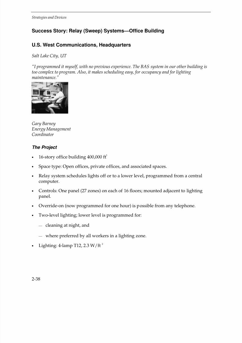
7/21/2019 Lighting Controls Patterns for Design
http://slidepdf.com/reader/full/lighting-controls-patterns-for-design 56/299
Strategies and Devices
2-38
Success Story: Relay (Sweep) Systems—Office Building
U.S. West Communications, Headquarters
Salt Lake City, UT
“I programmed it myself, with no previous experience. The BAS system in our other building istoo complex to program. Also, it makes scheduling easy, for occupancy and for lightingmaintenance.”
Gary BarneyEnergy ManagementCoordinator
The Project
• 16-story office building 400,000 ft2
• Space type: Open offices, private offices, and associated spaces.
• Relay system schedules lights off or to a lower level, programmed from a centralcomputer.
• Controls: One panel (27 zones) on each of 16 floors; mounted adjacent to lightingpanel.
• Override-on (now programmed for one hour) is possible from any telephone.
• Two-level lighting; lower level is programmed for:
— cleaning at night, and
— where preferred by all workers in a lighting zone.
• Lighting: 4-lamp T12, 2.3 W/ft 2

7/21/2019 Lighting Controls Patterns for Design
http://slidepdf.com/reader/full/lighting-controls-patterns-for-design 57/299
Strategies and Devices
2-39
U.S. West Communications Headquarters
Typical open-office area
Relay panel for one (of 16) floors

7/21/2019 Lighting Controls Patterns for Design
http://slidepdf.com/reader/full/lighting-controls-patterns-for-design 58/299
Strategies and Devices
2-40
Training area, unoccupied, lights programmed off (this is a flash photo)
Keys To Success
• Energy manager diligently monitors and programs the scheduling to achieveworker satisfaction and maximum energy savings.
• Relay system is perceived as easier to program than a BAS system.
• Detailed energy-use modeling by utility (Utah Power) helped select relay systemover other conservation projects.
• Virtually no re-wiring was required; panels were installed right off the breaker.
Economics
Estimated lighting use savings: 23%
Total Cost: $80,000Savings: $34,500/yrPayback: 2.3 years
For additional Case Studies, see Chapter 6, Success Stories (page 6-1)

7/21/2019 Lighting Controls Patterns for Design
http://slidepdf.com/reader/full/lighting-controls-patterns-for-design 59/299
Strategies and Devices
2-41
Lesson Learned: Relay (Sweep) System—Office Building
LESSSON:
It’s not just having controls, but taking advantage of them.
The Project
• Three-story office building, 240,000 ft2
• Open offices, private offices, and conference rooms
• One relay panel on each floor, 14 lighting zones per floor
• Schedule: All lights on at 6:00 a.m. and off at 6:00 p.m. (Emergency lights stay on inaisles and corridors.)
• Override: Lights flash twice five minutes before scheduled off time. Occupants canturn lights on for additional two hours at wall switches.
• Lighting: T8, electronic ballasts, 0.9 W/ft2
Metered lighting compared to occupancy for one floor on a typical day.
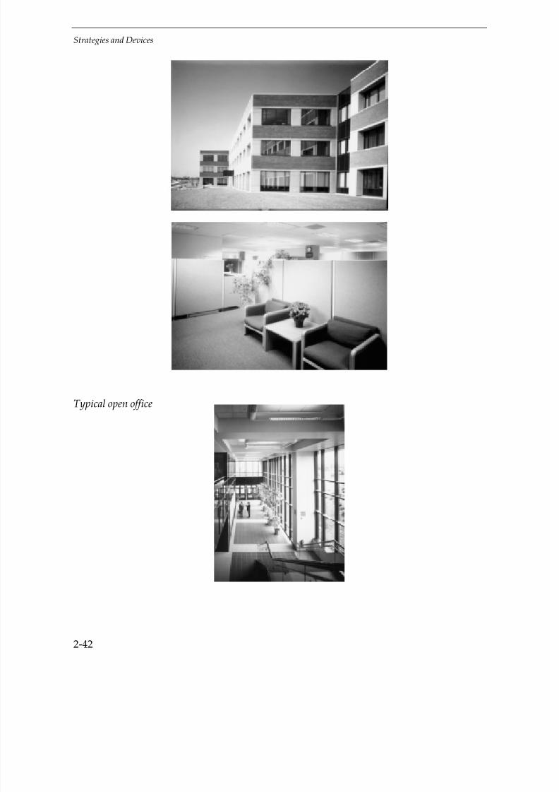
7/21/2019 Lighting Controls Patterns for Design
http://slidepdf.com/reader/full/lighting-controls-patterns-for-design 60/299
Strategies and Devices
2-42
Typical open office
7/21/2019 Lighting Controls Patterns for Design
http://slidepdf.com/reader/full/lighting-controls-patterns-for-design 61/299
Strategies and Devices
2-43
The Problem
• The lights were scheduled on longer than needed.
• The override time was too long
• The 4-6 override switches in each location were not labelled, and multiple zoneswere being overridden “on” unnecessarily.
• Analysis showed that:
— Lights are on longer than they need to be
— During the evening cleaning, not all lights should be on
— At night, scheduling is good at holding lights off
The Solution
• After coordination with building personnel, the designer recommended:
— Schedule: One-hour later on time (7:00 a.m.)
— Override: Reduce override time from two hours to one hour
— Switches: Label each switch with the zone it controls; post a sign “Turn lights ononly for your area”
• The result should be:
— Most lights on later in the morning
— Only about half of lights on in the evening for cleaning
— Savings of about 2 full-load hours per day, $9,000/yr—about one-half of thepotential savings (for an ideal system)
Key to strategies
Good application
Limited application
(See page 2-3 for key to symbols)

7/21/2019 Lighting Controls Patterns for Design
http://slidepdf.com/reader/full/lighting-controls-patterns-for-design 62/299
Strategies and Devices
2-44
Advanced Relay Systems
It is possible to use electronics to expand a central relay system to provide most energymanagement strategies. The on/off relay can be energized according to time, motionsensors, and/or manual switches. Dimming for daylighting and lumen-maintenance iscontrolled by photsensors in the affected spaces. And demand limiting is possible withadvanced relay systems that have building-wide control.
Note: Similar functions may be possible with a powerline-carrier control system. Newtechnologies providing better reliability and immunity to interference are underdevelopment and, in the future, may make this approach very attractive in existing buildings.
Wallbox Local Master Controller
In this type of system, a wallbox controller integrates the control functions. Forexample, a wallbox controller could contain on/off switching using a PIR motion sensorand permit the connection of additional PIR sensor(s) to cover a larger room. It could
also allow the connection of a photosensor and let the user manually dim the lightinglevel below the daylighting set-point. An advantage of this system is simplecommissioning: adjustments are made under the wallbox coverplate. The disadvantagesare 1) the system, like a wallbox occupancy sensor, won’t control very large spaces, and2) it can’t connect to building-wide energy management or demand-limiting systems.Because special wiring is required, this system is best for new construction and majorremodeling.
EXAMPLE COMBINED-CONTROL SYSTEM

7/21/2019 Lighting Controls Patterns for Design
http://slidepdf.com/reader/full/lighting-controls-patterns-for-design 63/299
Strategies and Devices
2-45
Local Master Controller Above the Ceiling
In this type of system, a concealed controller box above the ceiling can connect to aphotosensor, motion sensor(s), and a wallbox on/off dimmer, and interface with a building automation system or demand-limiting system. The controller box contains the
on/off power relay, the transformer for the electronics, and the circuits needed tointerconnect the various devices and drive the lighting fixtures. While this controller is better for building-wide connections and large spaces than a wallbox controller,commissioning is more difficult because adjustments are made at the ceiling-mountedsensors. Special wiring is required with this type of system also, but a retrofit might be a bit easier than with a wallbox system.
Smart Ballast
This fairly new product is more like a network, in which each ballast has it’s own
“brains” and the means to communicate with other ballasts via low-voltage wiring.It calibrates and functions much like a local master controller above the ceiling.
Summary
This chapter described:
Strategies—lighting control approaches that are used to save energy conveniently.These are concepts not equipment.
•
Occupancy Responsive triggers lights in response to movement or sound.• Timing schedules lights on and off
• Manual Dimming lets the occupant adjust the brightness.
• Daylighting dims or douses lights to account for daylight level.
• Lumen-maintenance reduces over-lighting when lights are new and clean.
• Tuning calibrates lights to what’s needed.
• Adaptation Compensation dims lights a bit inside when it’s dark outside.
• Load Shedding reduces lighting at time of peak demand.
Devices—pieces of equipment that are used to implement those Strategies.
• Manual Switches can do a lot of things, if crudely.
• Occupancy Sensors watch and switch.

7/21/2019 Lighting Controls Patterns for Design
http://slidepdf.com/reader/full/lighting-controls-patterns-for-design 64/299
Strategies and Devices
2-46
• Personal Occupancy Sensors watch just you.
• Timers let you order up a few minutes of light.
• Time Clocks switch lights on and off per time of day.
• Manual Dimmers let you twist or slide to taste.
• Photoelectric Controls automatically switch or dim lights according to the amount of light sensed.
Systems—more complex combinations of components that often include a logiccomponent such as a programmable relay.
• Powerline-Carrier Systems piggyback control signals on other wires.
• Relay Systems switch different circuits, by time or other control signals.
• Building Automation Systems can automate everything in the building.
• Combined Controls mix devices, possibly with automatic coordination.
It’s important to understand these basic lighting controls concepts and the hardware before going on to actual controls design and implementation, which are discussed inthe following chapters.
Exercises
Circle, check, write in, or poke your finger through the correct answer:
1. Lighting controls may:
a) Reduce lighting power
b) Reduce the time lights are on
c) Both
2. Insert either “Strategy,” “Device,” or “System” in each box:
Goal
Pieces of Equipment:
Pisces + PowerControl + Logic:
Easy, huh?

7/21/2019 Lighting Controls Patterns for Design
http://slidepdf.com/reader/full/lighting-controls-patterns-for-design 65/299
Strategies and Devices
2-47
3. Match each device with the strategy(s) it accomplishes
Occupancy Sensors Timing
Timers Daylighting
Time Clocks OccupancyResponsive
Photosensors
4. If a photosensor is located so it senses light from the light it controls, it is a (n):
a) Open-Loop control
b) Closed-Loop control
5. For Photosensors to accomplish Tuning and Lumen-Maintenance, they must be:
a) Open-Loop control
b) Closed-Loop control
6. An Adaptation Compensation control would lower light levels:
a) At night
b) During the day
7. Ultrasonic occupancy sensors (circle one):
a) Are better at “seeing around corners” than are PIR
b) Are better in high spaces than PIR
c) Detect body heat crossing zones of detection
d) All of the above
8. Wallbox occupancy sensors (choose one):
a) Are best for large rooms
b) May be PIR or ultrasonic
c) Use belly button lint as a key ingredient
d) All of the above

7/21/2019 Lighting Controls Patterns for Design
http://slidepdf.com/reader/full/lighting-controls-patterns-for-design 66/299
Strategies and Devices
2-48
9. Which of following is generally the most expensive type of occupancy sensing:
a) Audible (noise)
b) Passive Infrared
c) Ultrasonic
d) Multiple-technology
10. Which one of the following statements about occupancy sensor features is true:
a) An impending shutoff warning has no disadvantages
b) An auxiliary switch (“dry contacts”) may control HVAC, connect to a BuildingAutomation System (BAS), or both
c) A light sensor within a wallbox occupancy sensor is in a good location to sense
daylight on the workplace
d) All are true
11. Which one is true of powerline-carrier systems:
a) Control can be accomplished without rewiring
b) There is never interference from computers and other electronics
c) They can accomplish almost any control strategy well
d) All of the above
12. Relay Systems (choose one):
a) Use mostly low-voltage wiring
b) Can incorporate various devices such as occupancy sensors and timers
c) Are less useful for dimming than for other Strategies
d) All of the above
13. Which one of the following is not true about BAS systems:
a) They are generally the most expensive lighting control solution
b) They are identical to Combined Control Systems
c) They usually control HVAC systems

7/21/2019 Lighting Controls Patterns for Design
http://slidepdf.com/reader/full/lighting-controls-patterns-for-design 67/299
Strategies and Devices
2-49
14. With this book, which one of the following could not design lighting controls:
a) A registered P.E.
b) A registered architect
c) An entry-level designer
d) A monkey

7/21/2019 Lighting Controls Patterns for Design
http://slidepdf.com/reader/full/lighting-controls-patterns-for-design 68/299
2-50

7/21/2019 Lighting Controls Patterns for Design
http://slidepdf.com/reader/full/lighting-controls-patterns-for-design 69/299
3-1
3DESIGN PROCESS
Introduction
This chapter describes the process of designing lighting controls:
• Deciding which controls to use
•
Starting a design
• Avoiding pitfalls
• Debunking myths
• Considering advanced control design
You have a lot of things to think about.
Tip:
Don’t Wait!
Consider lighting controls while the lighting itself is being designed. A controlsstrategy may dictate the type of fixture used or the way fixtures are circuited.For example, lights controlled by an occupancy sensor or photosensor should becircuited together.
Design
budget
Building
budget
Client desires
Saturday
night
Deadline
Convenience
Economics
Codes

7/21/2019 Lighting Controls Patterns for Design
http://slidepdf.com/reader/full/lighting-controls-patterns-for-design 70/299
Design Process
3-2
Which Controls to Use
Before talking to sales reps or diving into detailed economic calculations, examine a few basics. Deciding on controls may be simpler than you expect.
Note that you must always meet codes. They may require anything from a minimumnumber of manual switches to automatic shutoff devices. See Appendix B, Codes(p. B-1), for details.
Step One: Identify Client Desires
“Nice customs curtsey to great kings.” —William Shakespeare
It may seem obvious, but make sure you understand any specific requirements ordesires the client may have. This doesn’t take your imagination; it takes talking to theclient—both to the bosses and to the workers.
The bosses may want dimmers, daylighting, or an energy showcase. They may salivateat the thought of workers’ absences being detected. And they may have guidelines onwhat is a good payback (“Six months maximum.” Yikes.)
The workers may have specific illumination requirements, or may have somemisperceptions about controls that you can correct. (“I don’t have to clap my hands?”)
Tip:
Be up-front
Occupants may be suspicious of controls. Let them know what the proposed controldoes, how it works, and what it saves.
Lighting
Controls

7/21/2019 Lighting Controls Patterns for Design
http://slidepdf.com/reader/full/lighting-controls-patterns-for-design 71/299
Design Process
3-3
No-Brainers
Step Two: Look for Slam Dunks
There are certain sure things that, like the “slam dunk” in basketball, take a major foul-up to go wrong. Lighting controls “slam dunks” are energy efficient controls withextremely short payback periods. “Slam dunks” include:
• Photocell controls for outdoor road, sign, and parking lot lighting
• Outdoor motion sensors for residential and commercial fluorescent andincandescent security lighting
• Motion sensors in seldom-used areas where lights stay on
• Mechanical and electronic timers for janitor closets, infrared heat lamps, and othersimple brief access or short-use situations
•
Time clock controls for retail store display lighting.You may discover a “slam-dunk” opportunity in any project. The nice thing about a“slam-dunk” is that your decision is made — for that area, you may be done!
Step Three: Identify Logical Choices
This is just a first cut to find which controls are logical candidates. For each space typeand for the building as a whole, go through the questions at the bottom of this page.
If the building has a Building Automation System (BAS), it may make sense to include
lighting circuits, at least for large zones, as points in the system. For a small zone, suchas a private office, a BAS point is usually overkill (spending maybe $500 to saveperhaps $25 a year by scheduling). See page 2-36.

7/21/2019 Lighting Controls Patterns for Design
http://slidepdf.com/reader/full/lighting-controls-patterns-for-design 72/299
Design Process
3-4
Space type and Control Device Application Matrix
The matrix on the next page is a quick guide to the best control devices to use for a broad range of space types. Space types shown in bold are illustrated by DesignPatterns in Chapter 5 (page 5-1).
IDENTIFY LOGICAL CHOICES
Question to Ask If “Yes,” Consider:
• Is space use erratic (e.g.,a private office where theoccupant is randomly absentabout a third of the time or awarehouse aisle)?
OccupancySensors
Timers
• Is space use non-continuousand predictable (e.g., a mall orpublic building)?
Time Clocks
• Is there exterior lighting?
Photosensors
• Is there a lot of daylight fromwindows or skylights?
• Is there a functional need formanual dimming (e.g., in a
conference room)?
Manual Dimmers
• Can lighting levels be reducedfor some or all occupants?
• Are there many large spacesto be controlled?
Relay System(with any of above)

7/21/2019 Lighting Controls Patterns for Design
http://slidepdf.com/reader/full/lighting-controls-patterns-for-design 73/299
Design Process
3-5
SPACE TYPE AND CONTROL DEVICE APPLICATION MATRIX
Control Device
Space types in bold below
are illustrated in Chapter 5,
Design Patterns, on pagenumbers shown.
Manual
Wallbox
Switch
Wallbox
Occ
Sensor
Ceiling/
wall
Occ Sensor
Personal
Occ
Sensor
Timer Time
Clock
Device
Manual
Wallbox
Dimmer
Wireless
Remote
Dimmer
Photo
switch
Photo
sensor
Space Type
Assembly & Light Manufacturing • • ° •
Auditoriums (p. 5-3) • • • •
Classrooms (p. 5-7) • • ° ° •
Concourses, Lobbies, Malls • • • •
Conference Rooms (p. 5-17) • ° • • • •
Exterior Lighting • ° • •
File/Storage Rooms(p. 5-26) • • •
Gymnasiums (p. 5-32) • • °
Hallways (p. 5-36) • • • • °
Laboratories (p. 5-48) • • ° • •
Library Reading Areas(p. 5-59) • • ° •
Library Stacks (p. 5-68) • • • °
Locker Rooms • • °
Lunch/Break Rooms • ° • ° ° •
Medical Suite/Exam Rooms • ° •
Museums • ° • ° °
Open Offices (p. 5-79) • ° • • ° •
Private Offices (p. 5-87) • • • • • ° •
Restaurants • ° • ° °
Restrooms (p. 5-97) • ° • °
Retail Sales Areas (p. 5-101) • ° ° ° ° °
Warehouses (p. 5-109) • • ° ° °
• Good device application ° Limited device application

7/21/2019 Lighting Controls Patterns for Design
http://slidepdf.com/reader/full/lighting-controls-patterns-for-design 74/299
Design Process
3-6
Step Four: Consider Electric Rate
To help select from among choices indicated on the previous pages, consider yourelectric rate. A low electric rate justifies simple or single controls, whereas a high electricrate can justify more complex or multiple controls. In the chart below, use an
approximate cents-per-kWh value (including demand), or calculate the exact rate(see page C-3).
Tip:
Just one step
This is just one step, one cut through the problem. Other factors may dominate. Forexample, multiple controls that save an unusually large amount of energy may makesense even in an area where the electric rate is low. See Appendix C, Economics(p. C-2), for more complete discussion of economics.
Step Five: Consider Electric Use Profile
Control choices may be further narrowed by considering when power is used. Use your building’s daily usage (demand) profile to help select controls. See table on next page.
Step Six: Do Prospecting (Optional)
In an existing building, you can test for how much energy a proposed lighting control
would save by temporarily installing a light logger with an attached occupancy sensoror photosensor. The light logger records when the lights are on and the sensor indicateswhen they would have been turned off or dimmed. This data, typically after one or twoweeks’ installation, is downloaded to one’s own computer and analyzed by softwaresupplied with the logger to calculate potential energy savings.
Note: EPRI has developed the Lighting Evaluation System (LES) and the LightingDiagnostic and Commissioning System (LDCS),which are used with a specified brandof light logger and attachments, to do this analysis. See page D-1.
For more information on light loggers, see page C-8.

7/21/2019 Lighting Controls Patterns for Design
http://slidepdf.com/reader/full/lighting-controls-patterns-for-design 75/299
Design Process
3-7
CONSIDER ELECTRIC RATE
For This Electric Rate(¢/kWh, incl. demand)
Usually Consider:
¢¢¢¢¢¢¢¢¢¢¢¢¢¢¢¢
¢¢¢¢¢¢¢¢¢¢¢¢¢¢¢¢¢¢¢¢¢¢¢¢¢¢¢¢¢¢¢¢
Simple controls that save a lot of energy
• Photoelectric switches for outdoor lighting
• Occupancy sensors in private offices, conference rooms, etc.
• Time clocks for retail store lighting
5¢¢¢¢¢¢¢¢¢¢¢¢¢¢¢¢¢¢¢¢¢¢¢¢¢¢¢¢¢¢¢¢¢
¢¢¢¢¢¢¢¢¢¢¢¢¢¢¢¢¢¢¢¢¢¢¢¢¢¢¢¢¢¢¢¢
¢¢¢¢¢¢¢¢¢¢¢¢¢¢¢¢
Just one control per light
• Occupancy sensors with manual 2-level control in privateoffices with windows (If the demand rate is high, considerphotosensors for daylight dimming.)
• Photoelectric switching or dimming in large indoor spaceswith high daylight levels
• Workstation occupancy sensors
10¢ ¢¢¢¢¢¢¢¢¢¢¢¢¢¢¢¢¢¢¢¢¢¢¢¢¢¢¢¢¢¢¢¢
¢¢¢¢¢¢¢¢¢¢¢¢¢¢¢¢¢¢¢¢¢¢¢¢¢¢¢¢¢¢¢¢
¢¢¢¢¢¢¢¢¢¢¢¢¢¢¢¢
Multiple controls• Photosensors for daylight dimming AND time clocks or
occupancy sensors in open offices with windows
15¢ ¢¢¢¢¢¢¢¢¢¢¢¢¢¢¢¢¢¢¢¢¢¢¢¢¢¢¢¢¢¢¢¢
A sensible combination of controls
• Photosensors + Occupancy sensors + Manual dimmers

7/21/2019 Lighting Controls Patterns for Design
http://slidepdf.com/reader/full/lighting-controls-patterns-for-design 76/299
Design Process
3-8
CONSIDER ELECTRIC USE PROFILE
For This Profile of BuildingElectricity Usage Concentrate on:
Peak-use(e.g., “9 to 5”office building)
Controls that reduce peak demand
• Daylighting controls and occupancysensors for tenant spaces
• Time clocks for common spaces
Extended-hour(e.g., offices with flex-timeor extended hours)
Controls sensitive to unpredictable use
• Occupancy sensors• Manual dimmers for adaptation
compensation at night
24-hour(e.g., hospital)
Controls for day and night lightingreduction
• Photosensors for daylighting•
Manual dimmers for adaptationcompensation
Event space(e.g., ballroom)
Manual controls usually work best(if properly managed)
Simple light logger magnetically attached.
7/21/2019 Lighting Controls Patterns for Design
http://slidepdf.com/reader/full/lighting-controls-patterns-for-design 77/299
Design Process
3-9
Tip:
Borrow one
Some lighting controls representatives will lend and/or install light loggers to
demonstrate potential savings from their products.
Step Seven: Do Economic Calculations (Optional)
Sometimes, you can decide on controls just by using the guidelines above. Usually,though, you’ll want to know the simple payback for a proposed controls project.Obviously, the analysis is more justified (i.e., covered by fee) when you’re decidingcontrols for twenty private offices rather than one.
Use the “Payback on Controls” plot on next page to estimate the payback for a project.You have to know:
• Approximate cost of controls
• Electric rate ($/kWh including demand charges if applicable)
• An estimate of how many hours per year the controls reduce lighting usage
• Lighting kW or W/ft2
Note: Try to develop real values for these inputs; don’t guess at them.
If you can’t determine the actual cost of controls, use this table to determine whichcontrol cost to use on the plot:
DEFAULT CONTROL COST (FOR PLOT)
Control type Large zone (2000 ft2) Small zone (150 ft
2)
Simple control (Occupancysensor, timer, or time clock)
LOW COST MEDIUM COST
More complex control (manualfluorescent dimmer,photosensor, or relay system)
MEDIUM COST HIGH COST

7/21/2019 Lighting Controls Patterns for Design
http://slidepdf.com/reader/full/lighting-controls-patterns-for-design 78/299
Design Process
3-10
The following assumptions are made:
• Lighting: 1.3 W/Ft2 (see next page for other W/ft
2)
• Savings multiplier, to include net cooling and heating side effects: 1.15 (New York
City climate) — see page C-3.
Payback on Controls
Example: $0.08/kWh; Save 1300 hr/year; Medium Cost controls ANSWER: About 3.2 –year payback
For CONTROL COST=

7/21/2019 Lighting Controls Patterns for Design
http://slidepdf.com/reader/full/lighting-controls-patterns-for-design 79/299
Design Process
3-11
Simple correction for lighting density other than 1.3 W/ft2
FOR W/FT2
0.6 0.8 1.0 1.3 1.5 2.0
MULTIPLYPAYBACK BY:
2.2 1.6 1.3 1.0 0.9 0.6
(Multiplier = 1.3 / (your W/ft2)
See page C-5 for actual calculation and additional factors.
Tip:
Save how much?
The amount saved by automatic controls depends on how diligent manual switchingis already.
An occupancy sensor retrofit saved only 10 to 20% at the Florida Solar Energy Centeroffices, despite fine-tuning of the sensors. Workers were already vigilant in turningout lights, making additional savings difficult.
Make your “before” realistic.
The hours per year savings to be used are “full-load” hours, that is, the hours that lightsare turned off completely, or, if dimmed, the hours they would be turned off to equalthe same energy savings. For example, if dimmed to 30% power for 2000 hours, the full-
load hours saved is 1400 hours (70% reduction x 2000 hours). Include only savingsbeyond what occupants would save by manual control anyway (see “Tip” above).
To find the kW or W/ft2 value to use, you need to do some sort of audit. See page C-3.
Tip:
HVAC effects
Heating and air-conditioning cost effects are nearly always secondary to the lightingimpact itself, but the net HVAC effect virtually always adds to the lighting savings,
even in cold climates. See pages C-2, C-3.

7/21/2019 Lighting Controls Patterns for Design
http://slidepdf.com/reader/full/lighting-controls-patterns-for-design 80/299
Design Process
3-12
Designing Controls
A Chinese sage once said, “The longest journey begins with the first call to a sales rep.”Or maybe it was opening the first catalog, talking with a wise elder, or looking at asuccessful installation. It should have been reading this book, but it wasn’t written yet.
Designing controls is no tougher than picking out a car, and imagine the dweebs thatmanage to do that! Just start accumulating information, preferably from severalviewpoints (not only from people trying to sell you something), and use common sense.
It’s not rocket science. (It’s more like brain surgery.) You won’t destroy Wisconsin byputting in a wallbox occupancy sensor.
After choosing the controls that make the most sense (above), you next have to finalizethe decision and start the actual design.
Do the following:
• See Chapter 5, Design Patterns (p. 5-1):
1. Check the first page for each space type, e.g., private offices, for Key Problems andIssues and Best Control Strategies for the space type.
2. Use the Patterns as a detailed design guide and template, even if the space you’redesigning isn’t exactly represented there.
• Review the manufacturers’ product catalogs for the controls you’re considering.These catalogs contain additional design guides, sample specifications, and otheruseful information that will help you to compare several devices and select one ormore that work best. (See next page)
• Call the agents or sales reps for the products you’re interested in. Many times you’lldiscover the agent has more up-to-date information and may be able to show younew products and applications information that isn’t in your catalog. Most agentswill also help lay out and specify the controls — for the products they sell, of course!
• Do a trial installation, to try different controls and manufacturers.(See “Trial Installations” page 3-14.)

7/21/2019 Lighting Controls Patterns for Design
http://slidepdf.com/reader/full/lighting-controls-patterns-for-design 81/299
Design Process
3-13
Tip:
Be consistent
Once you’ve decided to put PIR ceiling-mounted occupancy sensors in private offices,
put the same type of sensor in approximately the same place in every office, even if some offices might be better suited for a time clock or other controller.
Consistency will make operations and maintenance easier, and the difference inenergy savings will be minor.
Help From Manufacturers
Guides
Controls’ manufacturers provide not only catalogs but also design and applicationguides. These guides are either contained in the catalog or furnished separately by themanufacturer’s sales agent — so ask for them.
Coverage Diagrams
These catalog drawings illustrate the sensitivity patterns of occupancy sensors.These patterns are usually shown in plan view (two dimensions) and may also includesectional elevations of the coverage.
Coverage diagrams are generally used when “eyeballing it,” which is quick and okay todo in small spaces but not recommended in more complex spaces where it’s easy tomake an error.
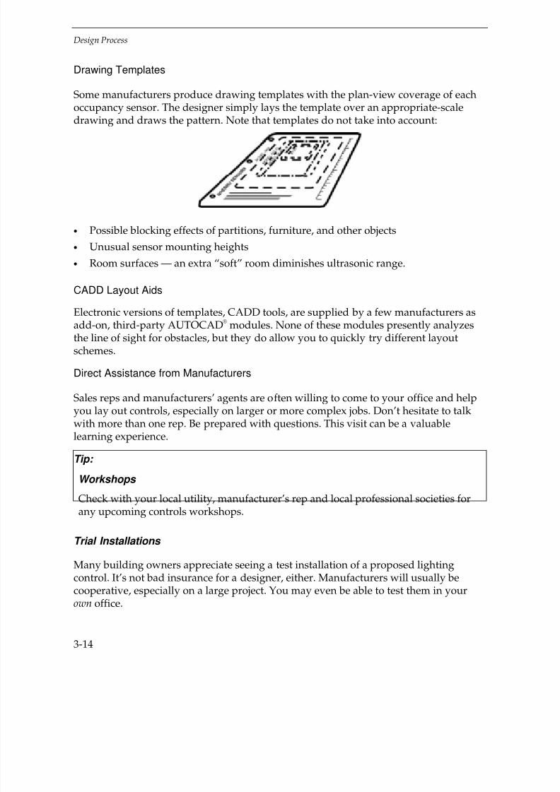
7/21/2019 Lighting Controls Patterns for Design
http://slidepdf.com/reader/full/lighting-controls-patterns-for-design 82/299
Design Process
3-14
Drawing Templates
Some manufacturers produce drawing templates with the plan-view coverage of eachoccupancy sensor. The designer simply lays the template over an appropriate-scaledrawing and draws the pattern. Note that templates do not take into account:
• Possible blocking effects of partitions, furniture, and other objects
• Unusual sensor mounting heights
• Room surfaces — an extra “soft” room diminishes ultrasonic range.
CADD Layout Aids
Electronic versions of templates, CADD tools, are supplied by a few manufacturers asadd-on, third-party AUTOCAD® modules. None of these modules presently analyzesthe line of sight for obstacles, but they do allow you to quickly try different layoutschemes.
Direct Assistance from Manufacturers
Sales reps and manufacturers’ agents are often willing to come to your office and helpyou lay out controls, especially on larger or more complex jobs. Don’t hesitate to talkwith more than one rep. Be prepared with questions. This visit can be a valuablelearning experience.
Tip:
Workshops
Check with your local utility, manufacturer’s rep and local professional societies forany upcoming controls workshops.
Trial Installations
Many building owners appreciate seeing a test installation of a proposed lightingcontrol. It’s not bad insurance for a designer, either. Manufacturers will usually becooperative, especially on a large project. You may even be able to test them in yourown office.
7/21/2019 Lighting Controls Patterns for Design
http://slidepdf.com/reader/full/lighting-controls-patterns-for-design 83/299
Design Process
3-15
• See how easy or difficult it is to install and commission the control device. Then livewith it for a few weeks. Don’t proceed with full installation until all the bugs areworked out. And don’t be afraid to reject the control; that’s a successful test too.
• On a large project, install competing products side by side for comparison.
• If possible, also have light loggers installed on the affected lighting to check energysavings. (See page 3-8.)
Tip:
Human factor
Results of a controls design can vary widely.
Conscientious people can control lights almost perfectly using only manual switches;resentful people can circumvent the most exotic controls system and render it useless.To assure that the people using the space don’t attack the new controls, work to get a“buy-in” by workers as well as management through mockups, follow-up service,post-occupancy evaluation, and other activities to let workers know “you care.”
Tips for a Successful Design
During the design phase:
• Involve the client and future controls’ users in decisions. Pay attention to their
desires and resistances.
• Do a trial installation (previous section). Let the client and building occupants getsome “hands-on” feel for the control and how it works.
• Be careful with pointy objects like pencils.
• Read and follow the design recommendations in the product literature.
• Get manufacturers’ agents to assist you.
During installation:
• Provide drawings marked up with coverage areas to help installers understand therationale for mounting locations, and to record your reasons for it.
• Read and follow the instructions contained with the product.

7/21/2019 Lighting Controls Patterns for Design
http://slidepdf.com/reader/full/lighting-controls-patterns-for-design 84/299
Design Process
3-16
• Get help from the manufacturer or his agent to learn how to adjust and commissiondevices and small systems.
• Have the manufacturer’s field engineer check out and commission larger and morecomplex systems.
Design Risks
Risks (and remedies) for specific devices were described in the previous chapter,Strategies and Devices. Below are some general design risks and ways to minimizethem.
“The better part of valor is discretion.” — William Shakespeare
Interference on Drawings
Risk: In some actual cases, if the drawings for the controls, HVAC, and lighting layoutshad been overlaid, they would have shown:
Nope, putting sensors inside grilles and lights wasn’t the intent, but the installer made avaliant effort!
Remedy: Coordinate the location of controls, HVAC, and lights. Consult the sensormanufacturer’s recommendations. Don’t be afraid to put notes on the drawing, as
below.

7/21/2019 Lighting Controls Patterns for Design
http://slidepdf.com/reader/full/lighting-controls-patterns-for-design 85/299
Design Process
3-17
Tip:
Sample note on drawing:
Occupancy sensors:
Maintain at least 6-foot clearance from supply and return air outlets, and at least2-foot clearance from lighting fixtures.
Misapplying Electronic Switches
Risk: Some programmable time clocks, electronic timers, and even electronic touchswitches are designed for use with incandescent loads only. Problems can occur whenthese devices are used with any type of fluorescent load. For example, under-loadingproblems with occupancy sensors are common (see page 2-21).
Remedy: Check catalogs to assure compatibility — devices not suitable for fluorescent
loads are labeled accordingly. If in doubt, ask the manufacturer.
Bidding and Substitutions
Risk: There is a danger that you won’t get the make and model of control you specify,especially if a job is competitively bid.
Substitutions:False Economy
A contractor will often come to the owner with an enticing offer like: “I can save you$10,000 with this other widget...Sure, it can do the same thing.” The contractor willprobably pass on only part of the savings, and the owner might lose a lot more in value.And you’ll be the loser when the control doesn’t work right.

7/21/2019 Lighting Controls Patterns for Design
http://slidepdf.com/reader/full/lighting-controls-patterns-for-design 86/299
Design Process
3-18
Tip:
Horror story
An owner “saved” $30,000 when he accepted the contractor’s proposal to substitute a
photosensor dimming system made of “built-up” components instead of the single-source system specified. The system failed to dim lights resulting in $30,000 in fixes,much frustration, and a one-year delay in dimming.
Remedy: If a job requires multiple proposals, avoid inappropriate substitutions bydesigning, when possible, with devices that are available from several manufacturers.For occupancy sensors, this would mean sensors with the same coverage area andpattern. Just saying “or equal” may yield “sort of like.”
Play the devil’s advocate to think of ways the job could go wrong. Make sure you getwhat you want. Stick to your guns.
Tip:
Follow through
Make sure you have the opportunity, budget, and authority to really reviewsubmittals.
Myths
Both bonafide disasters and far-fetched stories are the legend of controls applications.While the risks above are real and people have little tolerance for lighting controls thatdon’t work well, other stories are just myths that you should be prepared to debunk.
So, for the record:
Myth: Lamp cycling due to controls results in short lamp life, and lamp replacementcosts swamp any energy savings that occur.
Fact: Even with frequent switching (up to about 40 on-off cycles a day—perhaps on
7 minutes and off 7 minutes all day) the marginal added energy savings from increasedswitching overcomes any added relamping costs. See page 2-18.
Myth: Lighting controls, notably dimmers, are simply resistors that use as much energyas they save.
7/21/2019 Lighting Controls Patterns for Design
http://slidepdf.com/reader/full/lighting-controls-patterns-for-design 87/299
Design Process
3-19
Fact: This was true 40 years ago, but virtually all modern lighting controls use highspeed switching, or other advanced means, to effectively reduce lighting energyconsumption.
Myth: Lighting and its control systems emit a lot of harmful radiation.
Fact: Lighting emits a small quantity of ultraviolet light and a fair amount of harmlessinfrared energy, but so little of any other potentially harmful radiation as to be of virtually no concern. (Ultrasonic sensors emit ultrasound, and some electromagneticinterference is possible with hearing aids, see page 2-20.)
Myth: Powerline-carrier systems that include lighting controls frequently behaveerratically.
Fact: They usually work well, but false switching even a fraction of 1% of the time is beyond most people’s tolerance.
Myth: The inrush into a lamp or ballast when they’re restarted consumes a lot moreenergy than you save by turning the light off.
Fact: Fluorescent or incandescent inrush consumes the equivalent of only a few secondsof normal use. If inrush current were significant, it would trip breakers and cause othermischief. Leaving a light on to save energy makes no sense. And remember, thatalthough frequent switching shortens lamp life it still saves money over-all(see page 2-18).
Myth: Harmonic distortion is a big problem when dimming.
Fact: Electronic fluorescent ballasts generally exhibit very low harmonics even whendimmed. Incandescent dimming, however, usually causes bad harmonic distortion.
Advanced Control Design
The objective of advanced control design is to save the maximum amount of energy byapplying every useful strategy to the space being designed. While each added strategymay save less than it would when applied alone (due to diminishing returns), the
strategies may cost less to apply in combination and thus be very cost-effective. Added benefits can be a high-tech or deluxe image, increased productivity, and closer overallcontrol of operations by management.

7/21/2019 Lighting Controls Patterns for Design
http://slidepdf.com/reader/full/lighting-controls-patterns-for-design 88/299
Design Process
3-20
Favorable conditions for advanced control design include some or all of the following:
• High average kWh rate
• High demand rate
• Significant daylight potential
• Long business or operating hours
• Hot climate and/or high internal loads (to give large air-conditioning benefits)
• A client that’s open to innovation and committed to commissioning and goodmaintenance
The obvious benefit of this design approach is maximizing lighting energy savings. In
the following examples, other hidden benefits show up to “sweeten the pot.”
Shopping Mall
This public shopping mall uses two strategies to dim lights:
• During the day, daylighting is used because of good available natural light.
• In the evening, adaptation compensation is used since a lower light level is sufficient(and actually preferred) when it’s dark outside.
In this case, an advanced control design saves both lighting energy cost and lightingsystem first cost. Halogen lamps, which cost less than fluorescent or HID lamps, are
DIM DAY AND NIGHTEnergy savings and visual comfort:
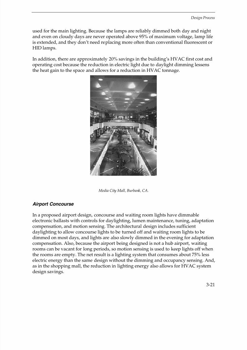
7/21/2019 Lighting Controls Patterns for Design
http://slidepdf.com/reader/full/lighting-controls-patterns-for-design 89/299
Design Process
3-21
used for the main lighting. Because the lamps are reliably dimmed both day and nightand even on cloudy days are never operated above 95% of maximum voltage, lamp lifeis extended, and they don’t need replacing more often than conventional fluorescent orHID lamps.
In addition, there are approximately 20% savings in the building’s HVAC first cost andoperating cost because the reduction in electric light due to daylight dimming lessensthe heat gain to the space and allows for a reduction in HVAC tonnage.
Media City Mall, Burbank, CA.
Airport Concourse
In a proposed airport design, concourse and waiting room lights have dimmableelectronic ballasts with controls for daylighting, lumen maintenance, tuning, adaptationcompensation, and motion sensing. The architectural design includes sufficientdaylighting to allow concourse lights to be turned off and waiting room lights to be
dimmed on most days, and lights are also slowly dimmed in the evening for adaptationcompensation. Also, because the airport being designed is not a hub airport, waitingrooms can be vacant for long periods, so motion sensing is used to keep lights off whenthe rooms are empty. The net result is a lighting system that consumes about 75% lesselectric energy than the same design without the dimming and occupancy sensing. And,as in the shopping mall, the reduction in lighting energy also allows for HVAC systemdesign savings.
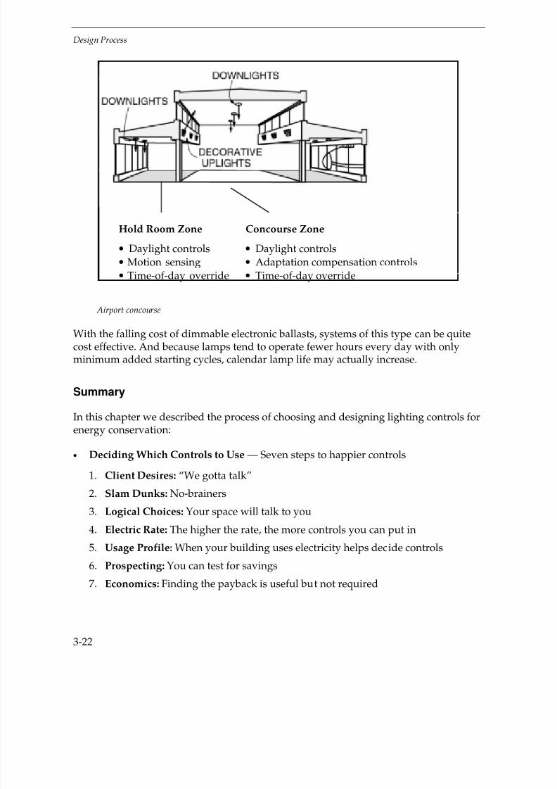
7/21/2019 Lighting Controls Patterns for Design
http://slidepdf.com/reader/full/lighting-controls-patterns-for-design 90/299
Design Process
3-22
Airport concourse
With the falling cost of dimmable electronic ballasts, systems of this type can be quitecost effective. And because lamps tend to operate fewer hours every day with onlyminimum added starting cycles, calendar lamp life may actually increase.
Summary
In this chapter we described the process of choosing and designing lighting controls forenergy conservation:
• Deciding Which Controls to Use — Seven steps to happier controls
1. Client Desires: “We gotta talk”
2. Slam Dunks: No-brainers
3. Logical Choices: Your space will talk to you
4. Electric Rate: The higher the rate, the more controls you can put in
5. Usage Profile: When your building uses electricity helps decide controls
6. Prospecting: You can test for savings
7. Economics: Finding the payback is useful but not required
Hold Room Zone Concourse Zone
• Daylight controls • Daylight controls
• Motion sensing • Adaptation compensation controls
• Time-of-day override • Time-of-day override
7/21/2019 Lighting Controls Patterns for Design
http://slidepdf.com/reader/full/lighting-controls-patterns-for-design 91/299
Design Process
3-23
• Starting a Design — Use the materials and savvy at hand
1. Help from Manufacturers: Use their resources
2. Trial Installations: Just dip your toe in first
• Tips For a Successful Design: How to minimize risks
• Design Risks: Sensors in diffusers, surprises from low bidders, etc.
• Myths: New York doesn’t dim when your lights go on; etc.
• Advanced Control Design: After you walk, Boogey!
In the next chapter, we jump ahead to what’s needed after the controls are installed tomake sure they work. Then, in Chapter 5, Design Patterns, controls are laid out inspecific space types as models for design.
Exercises
Find some way of indicating the correct answer:
1. If the client says they really want advanced lighting controls, you:
a) Tell them you don’t know how
b) Tell them the slightest change will require a lot more fee
c) Ask them what controls they’re interested in
2. Of the following, the first you do is:
a) Do a payback calculation on using satellite tracking for occupancy
b) Look for slam dunks
c) Finish the drawings
d) Go to lunch
3. Manufacturers’ reps:
a) Usually aren’t interested in helping you buy their products
b) Usually don’t know what their products are

7/21/2019 Lighting Controls Patterns for Design
http://slidepdf.com/reader/full/lighting-controls-patterns-for-design 92/299
Design Process
3-24
c) May actually lay out the job for you or find someone who can
d) Usually have little product information
4. Clever designers might:
a) Recommend a trial installation to test products
b) Borrow a logger from a manufacturer to check potential savings
c) Find a workshop on lighting controls
z) All of the above
Ψ) None of the above
5. Involving the future occupants and users in control decisions:
a) Is foolish
b) Will help you avoid disasters
c) Leads to a great social life
6. Which one of the following is true:
a) Checking sensor placements against lighting and mechanical drawings is
confusing and should be avoided
b) All electronic switches can be used with either fluorescent or incandescent loads
c) Contractors’ offers of controls substitutions are nearly always a good way to savemoney
d) All of the above
e) None of the above
7/21/2019 Lighting Controls Patterns for Design
http://slidepdf.com/reader/full/lighting-controls-patterns-for-design 93/299
4-1
4AFTER INSTALLATION
Introduction
More than lighting fixtures, lighting controls always need attention after they’reinstalled. This includes commissioning (always), maintenance (always), andtroubleshooting (often).
Commissioning
Commissioning is the adjusting and testing of controls after installation. It’s a necessarystep, not just insurance or a luxury, and must be part of the controls specification orpurchase agreement.
Commissioning goes far beyond a punch list (seeing if components are in place, etc.). Ittakes more than a walk-through to see if, for instance, a photosensor is dimming lightsproperly. Although commissioning adds cost — for a commissioning contractor,adjustments, and, likely, monitoring — it is quickly repaid by preventing complaints
and assuring savings.
The real issue is in making certain that it’s done:
• In new construction, the specifications should require devices to be properlyadjusted by the manufacturer or a trained technician according to themanufacturer’s recommendations.
• If the project does not have specifications, the facility manager should contact themanufacturer directly to get assistance with adjustments. In most cases, the localsales agent for the manufacturer can train the manager or staff.
It’s probably not a good idea to depend 100% on the contractor to make finaladjustments. Often the furniture and other factors that affect adjustments are notpresent during construction.
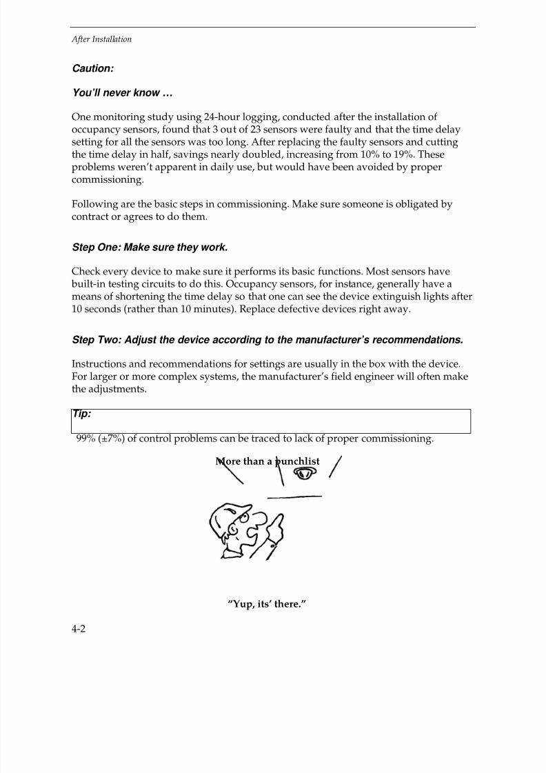
7/21/2019 Lighting Controls Patterns for Design
http://slidepdf.com/reader/full/lighting-controls-patterns-for-design 94/299
After Installation
4-2
Caution:
You’ll never know …
One monitoring study using 24-hour logging, conducted after the installation of
occupancy sensors, found that 3 out of 23 sensors were faulty and that the time delaysetting for all the sensors was too long. After replacing the faulty sensors and cuttingthe time delay in half, savings nearly doubled, increasing from 10% to 19%. Theseproblems weren’t apparent in daily use, but would have been avoided by propercommissioning.
Following are the basic steps in commissioning. Make sure someone is obligated bycontract or agrees to do them.
Step One: Make sure they work.
Check every device to make sure it performs its basic functions. Most sensors have built-in testing circuits to do this. Occupancy sensors, for instance, generally have ameans of shortening the time delay so that one can see the device extinguish lights after10 seconds (rather than 10 minutes). Replace defective devices right away.
Step Two: Adjust the device according to the manufacturer’s recommendations.
Instructions and recommendations for settings are usually in the box with the device.For larger or more complex systems, the manufacturer’s field engineer will often make
the adjustments.
Tip:
99% (±7%) of control problems can be traced to lack of proper commissioning.
More than a punchlist
“Yup, its’ there.”

7/21/2019 Lighting Controls Patterns for Design
http://slidepdf.com/reader/full/lighting-controls-patterns-for-design 95/299
After Installation
4-3
Tip:
“Help!”
Instruct the installer to “Contact the manufacturer for assistance prior to installation.”
This service is free.
Adjustments for specific devices are shown in the table below:
CONTROL ADJUSTMENTS
Device Adjustments Cautions
Occupancy
Sensors
Set:
• Sensitivity, if any, so itsenses proper area andactivity level. For PIRsensors, if there is nosensitivity adjustment, youcan use masking strips orbuilt-in shutters on the lensto modify the coverage area
• Time delay to recommendedtime (see Chapter 5,Patterns)
Have in place:
• Partitions
• Furnishings
• Representative activity(people, airflow, fans, etc.)
Make sure the sensor not onlydetects motion in the room, butdoesn’t detect motion inadjoining spaces such ashallways.
Timers Set the time delay
Time Clocks Set:
• On and off times
• Program functions, e.g.,occupied and unoccupieddays
Photosensors Set (per manufacture—methodsvary a lot):
• Time delay
• Response speed
• Light range control and/orsetpoints
Have in place:
• Partitions
• Furnishings
• Wall/floor coverings
• Window treatments
“Burn in” fluorescent lamps atfull light for at least 100 hours
before finalizing the sensoradjustments or dimming thelamps

7/21/2019 Lighting Controls Patterns for Design
http://slidepdf.com/reader/full/lighting-controls-patterns-for-design 96/299
After Installation
4-4
Generally, each device must be properly set to suit the space. Settings can be repeatedfrom device to device if conditions are the same and there are replicable setting markerson the device.
Make sure occupants and maintenance personnel are aware of:
• Normal operation of the device (e.g., that for occupancy sensors with manualon/auto off switching, lights aren’t supposed to come on upon entry).
• Calibration methods they may need to use in the future as conditions or desireschange.
• Maintenance required on the devices (e.g., cleaning photosensor lenses).
Caution:
Talk to them
A Florida school’s lighting energy usage went up 3% when occupancy sensors wereinstalled. The reason: teachers who previously turned off lights when they left the roomwere instead relying on the occupancy sensors, thus more energy was used because thelights stayed on during the 15-minute time-delay period.
Educating the educators resulted in better manual switching and positive savings.
Step Three: Listen to occupant feedback and make corrections quickly.
The majority of devices on the market have been “human engineered” to be acceptable
to most people when correctly designed, specified, and installed. And there will be veryfew problems if controls have been commissioned and calibrated prior to users moving into thespace. But if users move in concurrently with adjustments, there will likely beconsiderable attention paid to the devices, resulting in gossip, scuttlebutt, and oftensome form of insurrection.
7/21/2019 Lighting Controls Patterns for Design
http://slidepdf.com/reader/full/lighting-controls-patterns-for-design 97/299
After Installation
4-5
Tip:
Commissioning Tool
EPRI’s Lighting Diagnostic and Commissioning System (LDCS) is software used toanalyze the logged performance of sweep, photosensor, occupancy sensor, andcombined controls. Used with a specific manufacturer’s logger, the programautomates the time-consuming steps of initialization, or programming, of the loggersand evaluation of actual versus estimated savings. It can also analyze before- andafter- retrofit performance and calculate actual savings. Various plot and data outputformats are available. See page D-1.
Maintenance
And For Ever More. All systems require periodic maintenance.
• Make sure occupancy sensors are turning off lights when no one is present. Sensorscan malfunction, or, more likely, newly hung objects may be causing “false-ons.”
• Check switching schedules on timers and time clocks. Schedules may becomeconfused by holidays, leap years, daylight savings time, etc.
• Clean photocells and photosensors and make sure the controls are turning off ordimming lights when they should. Devices can malfunction or may have been tapedover, and shading devices may have been adjusted to limit daylight unnecessarily.
If systems are not maintained correctly, they will waste energy and/or be disconnectedor bypassed by the occupants.
Troubleshooting
React quickly and positively to erratic device behavior, device failures, and otherproblems.
Employees adapt well to controls that work. But controls that are improperly adjustedor fail repeatedly will be circumvented, regardless of management policy. Controls will
be short-circuited to force lights on and tape will appear over photocells. And, if all elsefails, employees will bring 150 Watt incandescent table lamps from home if the 120 Wattfluorescent lighting in their work stations seems “screwed up.” It doesn’t take a rocketscientist to figure the payback on that scenario.
7/21/2019 Lighting Controls Patterns for Design
http://slidepdf.com/reader/full/lighting-controls-patterns-for-design 98/299
After Installation
4-6
To solve a problem:
• First identify it and be able to state it clearly, e.g., “Lights go off after 15 minuteswhen someone’s working at the computer.”
•
Eliminate possible causes outside the control, e.g., faulty lighting.• Check if conditions have changed, for instance partitions moved or added.
• Check the occupant for pulse.
• Consult the “Risks” section for the particular device in Chapter 2, Strategies andDevices, for specific control problems.
Summary
Most control problems arise from improper commissioning (the adjustment and testingof controls in place). Make sure someone has the responsibility to:
• Make sure the controls work initially.
• Make adjustments per manufacturer’s specifications (possibly with themanufacturer’s help).
• Instruct local personnel on the operation and adjustment of the device.
• Listen to occupant feedback and assure continued correct performance of thecontrol.
React quickly to any perceived problem with controls and follow logical steps toidentify the source of the problem and solve it.
In the next chapter, Design Patterns, controls are laid out in specific space types asmodels for design.
Exercises
Shout out the correct answer:
1. What is the biggest source of control problems?
c) Lack of proper commissioninga) Bad designsn) Undependable equipment
2. Manufacturers’ recommendations and assistance:

7/21/2019 Lighting Controls Patterns for Design
http://slidepdf.com/reader/full/lighting-controls-patterns-for-design 99/299
After Installation
4-7
s) Are difficult to accessa) Can make you a herov) Usually entail a feee) Cannot be trusted
3. Which one is a good idea?
s) Repeating settings from one device to others similarly situatedo) Using calibrations “out of the box,” without adjusting
m) Calibrating the control prior to cluttering the room with furnishingse) Leaving calibration to the owner’s discretion
4. If the installed controls don’t save as much as they should:
k) Occupants will usually make them work properlyw) The owner will usually make them work properly
h) You’ll probably never hear about it

7/21/2019 Lighting Controls Patterns for Design
http://slidepdf.com/reader/full/lighting-controls-patterns-for-design 100/299
7/21/2019 Lighting Controls Patterns for Design
http://slidepdf.com/reader/full/lighting-controls-patterns-for-design 101/299
5-1
5DESIGN PATTERNS
Introduction
This chapter provides lighting control patterns for typical commercial spaces. The spacetypes shown represent the majority of commercial spaces where controlling lights tosave energy is occupant-friendly and cost effective.
The sections on each space type are laid out in the same way, and include the followingelements:
First page:
Perspective drawings of a typically-sized room showing furniture arrangement andwindow and door locations.
Key problems and issues.
An example of a conventional wiring diagram for a typical lighting system, showing
fixture type, power density, maintained empty-room illumination, and manualswitching method.
The best control strategies to use.
Successive pages:
Design patterns for each recommended strategy with an estimate of the likelysavings in lighting energy based on applying these strategies to a number of spaces building wide.
Each Design Pattern contains a plan-view installation diagram for one controlscenario for the space type. The text describes the device types to use, the devicefeatures and settings that work best, where to locate the devices, and how to wirethe devices into the lighting system.
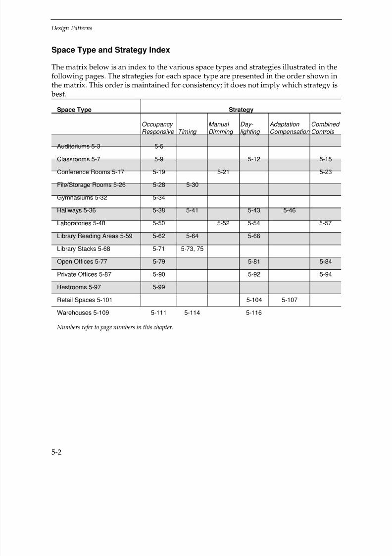
7/21/2019 Lighting Controls Patterns for Design
http://slidepdf.com/reader/full/lighting-controls-patterns-for-design 102/299
Design Patterns
5-2
Space Type and Strategy Index
The matrix below is an index to the various space types and strategies illustrated in thefollowing pages. The strategies for each space type are presented in the order shown inthe matrix. This order is maintained for consistency; it does not imply which strategy is
best.
Space Type Strategy
Occupancy Responsive Timing
Manual Dimming
Day- lighting
Adaptation Compensation
Combined Controls
Auditoriums 5-3 5-5
Classrooms 5-7 5-9 5-12 5-15
Conference Rooms 5-17 5-19 5-21 5-23
File/Storage Rooms 5-26 5-28 5-30
Gymnasiums 5-32 5-34
Hallways 5-36 5-38 5-41 5-43 5-46
Laboratories 5-48 5-50 5-52 5-54 5-57
Library Reading Areas 5-59 5-62 5-64 5-66
Library Stacks 5-68 5-71 5-73, 75
Open Offices 5-77 5-79 5-81 5-84
Private Offices 5-87 5-90 5-92 5-94
Restrooms 5-97 5-99
Retail Spaces 5-101 5-104 5-107
Warehouses 5-109 5-111 5-114 5-116
Numbers refer to page numbers in this chapter.

7/21/2019 Lighting Controls Patterns for Design
http://slidepdf.com/reader/full/lighting-controls-patterns-for-design 103/299
Design Patterns
5-3
Pattern Symbol Legend
Below are the symbols for lighting controls and electrical devices used in the patterns.
Note: Generic control devices are used in the patterns. To use the patterns mosteffectively, you should consult the manufacturer’s technical specifications to check
actual coverage templates (pattern, distance, and sensitivity), required coverageoverlap, control feature options, calibration setting limits, ambient temperaturesensitivity range, and electric load requirements (where applicable).
Auditoriums
Side View

7/21/2019 Lighting Controls Patterns for Design
http://slidepdf.com/reader/full/lighting-controls-patterns-for-design 104/299
Design Patterns
5-4
Conventional wiring
Conventional Wiring — ExampleFixture Type: Power density: 1.80 W/ft2
a - Downlight 2-CF18T5 Light level: Variable 15 to 70 FC b/c - Downlight tandem Switching: wired 3-CF18T5 One 3-way switch at each maine - Louvered step light 1-CF13T5 doorway controlling separate switch legsf - Adjustable mount 1-CF13T5
Key Problems and Issues
The usage and occupancy patterns for auditoriums vary primarily by institution type.
Auditoriums that function as lecture halls within colleges and universities may beoperated fairly continuously, while operation tends to be more discontinuous and lessregularly scheduled for auditoriums common to special event type buildings orelementary and high schools. Although occupant density is usually high, usermovement is typically limited to sitting and taking notes. Common occupancycharacteristics for auditoriums include:
Scheduled, continuous or discontinuous occupancy patterns
Limited occupant motion
Minimal user responsibility to turn off lights
Variations in light level
Most spaces have high ceilings, typically exceeding 15'. Seating areas generally slope orstep up from the presentation area to provide good lines-of-sight for the audience. Thesize of auditoriums range from under 1,500 ft
2 to over 5,000 ft
2. Because a high degree of
light level control is required to accommodate various types of presentations, the use of windows or skylights for daylighting is generally excluded.
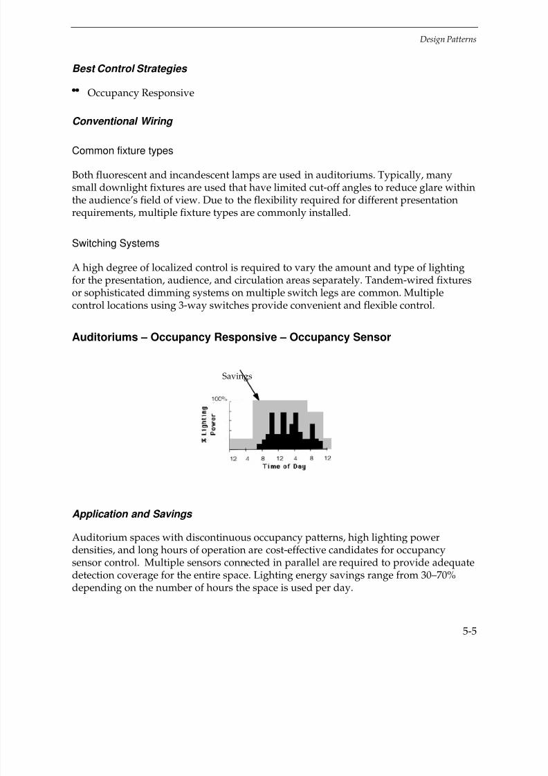
7/21/2019 Lighting Controls Patterns for Design
http://slidepdf.com/reader/full/lighting-controls-patterns-for-design 105/299
Design Patterns
5-5
Best Control Strategies
Occupancy Responsive
Conventional Wiring
Common fixture types
Both fluorescent and incandescent lamps are used in auditoriums. Typically, manysmall downlight fixtures are used that have limited cut-off angles to reduce glare withinthe audience’s field of view. Due to the flexibility required for different presentationrequirements, multiple fixture types are commonly installed.
Switching Systems
A high degree of localized control is required to vary the amount and type of lightingfor the presentation, audience, and circulation areas separately. Tandem-wired fixturesor sophisticated dimming systems on multiple switch legs are common. Multiplecontrol locations using 3-way switches provide convenient and flexible control.
Auditoriums – Occupancy Responsive – Occupancy Sensor
Application and Savings
Auditorium spaces with discontinuous occupancy patterns, high lighting powerdensities, and long hours of operation are cost-effective candidates for occupancysensor control. Multiple sensors connected in parallel are required to provide adequatedetection coverage for the entire space. Lighting energy savings range from 30–70%depending on the number of hours the space is used per day.
Savings

7/21/2019 Lighting Controls Patterns for Design
http://slidepdf.com/reader/full/lighting-controls-patterns-for-design 106/299
Design Patterns
5-6
Control Devices
Occupancy Sensor
Passive Infrared sensors work well when there are no hanging objects that could
block coverage.
Dual-mode sensors can normally detect all auditorium activity — coverage is not blocked by hanging objects.
Caution:
Check manufacturer’s application data for using ULT sensors if ceiling height isover 14–15'.
Device Locations
Mount PIR or dual-mode sensors on the wall 10' from the floor.
Good coverage detection overlap is mandatory due to limited occupant motion.
Ceiling mounted sensors can be installed but they are much more difficult to accessfor fine tuning of the sensor settings.
Recommended Features
Automatic on/off
Time out setting range to 30 minutes
Sensitivity calibration for dual-mode sensors
Recommended Settings
Set time-out setting in the medium range (10–15 minutes) to reduce the potentialfor “false-offs.”
Design Considerations
It is mandatory to provide manual switches or scene controls to turn off or dimvarious switch legs to control the lighting for different presentation formats.
Use multiple sensors connected in parallel to one or two transformer-relays tocontrol all the lights in the space.
Caution:
So that all lights are controlled together, don’t use independent occupancy sensorsto control separate switch circuits in the space.

7/21/2019 Lighting Controls Patterns for Design
http://slidepdf.com/reader/full/lighting-controls-patterns-for-design 107/299
Design Patterns
5-7
Multiple corner-mounted occupancy sensors (OS) connected in parallel to transformer-relays (TR) controlling alllighting circuits within the space except for emergency exit lights near doorways.
Classrooms
Side View
Top View
Typical sensor coverage detection zone

7/21/2019 Lighting Controls Patterns for Design
http://slidepdf.com/reader/full/lighting-controls-patterns-for-design 108/299
Design Patterns
5-8
Conventional wiring
Conventional Wiring — ExampleFixture Type: Power density: 1.30 W/ft2
1x8 suspended Light level: 50 FClouvered troffer Switching: Wall switch at the2-F32T8 lamps w/ doorelectronic balasts
Key Problems and Issues
The usage and occupancy patterns for a classroom depend on the type of institutionand the type/function of the classroom. K-12 grade classrooms are typically usedcontinuously during school hours, while technical school and college classrooms havediscontinuous use throughout the day. Different teachers, with different lighting controlneeds and preferences, may use the classroom each day. Primary tasks and task areasare reading and writing at the student and teacher desks, lecturing and writing at thechalkboard, and viewing audio visual materials at the front of the room. Teachersprovide most of the movement. Common occupancy characteristics for classroomsinclude:
Scheduled, continuous or discontinuous occupancy patterns
Periods of minimal occupant motion
Moderate requirement for the teacher to control the lighting
Classrooms are typically located on the perimeter of a building and have windows;however, they can also be located in the interior of a building. They range in size from500–1200 ft
2. Often, there is sufficient daylight to significantly reduce electric
illumination.

7/21/2019 Lighting Controls Patterns for Design
http://slidepdf.com/reader/full/lighting-controls-patterns-for-design 109/299
Design Patterns
5-9
Best Control Strategies
Occupancy Responsive
Daylighting
Combined Controls
Conventional Wiring
Common fixture types
Lighting systems include direct 3- and 4-lamp parabolic systems and direct/indirectpendant-mounted fixtures. Task lighting is typical at the chalk board or on side tables.
Switching Systems
Conventional switching incorporates a wall switch to control the ambient lighting,which is sometimes broken into control banks parallel to the windows. Task lightingis either switched with the main lights or at the task.
Classrooms – Occupancy Responsive – Occupancy Sensor
Application and Savings
Occupancy sensor control is an effective strategy for classrooms with discontinuous
occupancy patterns, long hours of use, and minimal daylighting potential. Mostclassrooms are small enough so that one occupancy sensor will provide adequatedetection coverage. Occupancy sensor type is determined by size of room, activity level,and openness of the space. Lighting energy savings ranges from 20–40% depending onthe diligence of the different users to turn the lights off when they leave.
Savings
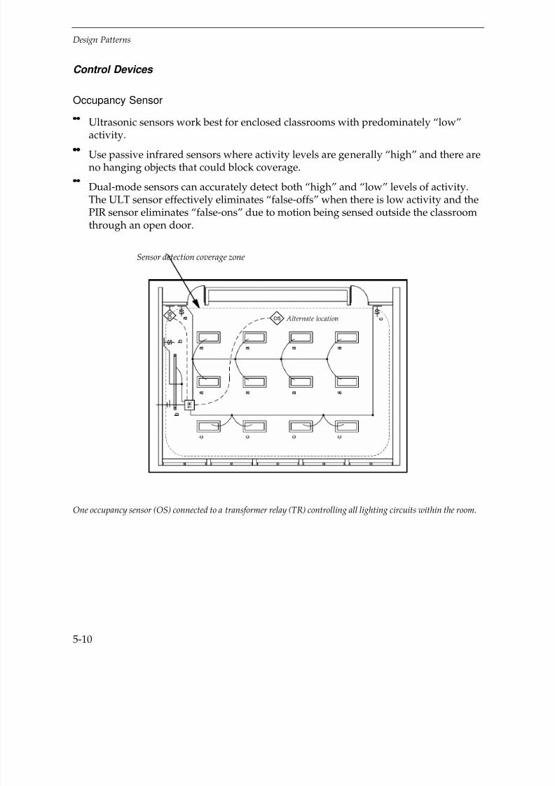
7/21/2019 Lighting Controls Patterns for Design
http://slidepdf.com/reader/full/lighting-controls-patterns-for-design 110/299
Design Patterns
5-10
Control Devices
Occupancy Sensor
Ultrasonic sensors work best for enclosed classrooms with predominately “low”
activity.
Use passive infrared sensors where activity levels are generally “high” and there areno hanging objects that could block coverage.
Dual-mode sensors can accurately detect both “high” and “low” levels of activity.The ULT sensor effectively eliminates “false-offs” when there is low activity and thePIR sensor eliminates “false-ons” due to motion being sensed outside the classroomthrough an open door.
One occupancy sensor (OS) connected to a transformer relay (TR) controlling all lighting circuits within the room.
Sensor detection coverage zone

7/21/2019 Lighting Controls Patterns for Design
http://slidepdf.com/reader/full/lighting-controls-patterns-for-design 111/299
Design Patterns
5-11
Device Locations
Locate a ULT sensor near the center of room but closer to the door wall(alternate location as shown).
Locate PIR or dual-mode sensors 7–10' from the floor on the door wall, preferably inthe corner at the instructor’s end of the room (in corner of room as shown).
Cautions:
Classrooms over 1,000 ft2 may require two PIR or dual-mode sensors.
Recommended Features
Manual on/Auto off
Time-out setting range to 30 minutes
Sensitivity calibration adjustment for ultrasonic and dual-mode sensors
Recommended Settings
Set the time-out setting in the low range (8–10 minutes) for “high” activityclassrooms, and in the medium range (10–15 minutes) for “low” activity rooms.
Set the sensitivity calibration after all furnishings are in place.
Design Considerations
It is mandatory to provide manual switches to turn all lights off for viewingA/V materials.
Use transformer-relays (TR) to control fixtures from low-voltage sensor signals.
If daylight is available, provide a separate switch leg for the first row of lightsparallel to the window to encourage manual control for daylight savings(as illustrated).

7/21/2019 Lighting Controls Patterns for Design
http://slidepdf.com/reader/full/lighting-controls-patterns-for-design 112/299
Design Patterns
5-12
Classrooms – Daylighting – Photosensor
Application and Savings
Perimeter classrooms with adequate window area and heavy occupancy duringdaylight hours are excellent candidates for daylighting controls. Good applicationsinclude classrooms with continuous use (K-12) that have high window head heights orhorizontal strip windows. Lighting energy savings range from 40–70%, depending onhow effectively the window design provides daylight, the length of time the classroomis operated, and when it gets dark. Energy savings typically coincides with peak building electrical use.
Control Devices
Photosensor
Local master controller
Dimming ballasts that dim to 10–20% for fixtures in the daylight zone.
Caution:
Stepped daylight sensors should only be used in classrooms where daylight issufficient to supply the required light level nearly all of the time, typical of older
schools buildings with high window head heights.
Savings
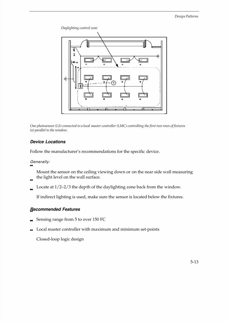
7/21/2019 Lighting Controls Patterns for Design
http://slidepdf.com/reader/full/lighting-controls-patterns-for-design 113/299
Design Patterns
5-13
One photosensor (LS) connected to a local master controller (LMC) controlling the first two rows of fixtures(a) parallel to the window.
Device Locations
Follow the manufacturer’s recommendations for the specific device.
Generally:
Mount the sensor on the ceiling viewing down or on the near side wall measuringthe light level on the wall surface.
Locate at 1/2–2/3 the depth of the daylighting zone back from the window.
If indirect lighting is used, make sure the sensor is located below the fixtures.
Recommended Features
Sensing range from 5 to over 150 FC
Local master controller with maximum and minimum set-points
Closed-loop logic design
Daylighting control zone

7/21/2019 Lighting Controls Patterns for Design
http://slidepdf.com/reader/full/lighting-controls-patterns-for-design 114/299
Design Patterns
5-14
Options:
Allows automatic incorporation of tuning and lumen-maintenance strategies.
Allows the addition of manual dimming for A/V control at little added first cost.
Recommended Settings
Follow manufacturer’s recommendations
Generally:
Set maximum light level at the design FC
Set minimum light level to make the space feel adequately lighted, usually20–30% of full light output.
Design Considerations
Control lights that are parallel to the window within a depth of 2–2.5 times thewindow head height.
If daylight distribution provides adequate daylight near the back of the room(i.e., the window head height is greater than 10 ft) use two daylighting zones:
— One daylight zone controlling the (a) fixtures and the other zone controlling the
(c) fixtures.
— Each classroom should have its own daylighting control circuits andphotosensor.

7/21/2019 Lighting Controls Patterns for Design
http://slidepdf.com/reader/full/lighting-controls-patterns-for-design 115/299
Design Patterns
5-15
Classrooms – Combined Controls – Occupancy Sensor + Manual Dimmer
Application and Savings
Occupancy sensoring and manual dimming are an excellent combination control
scheme for classrooms that operate for long hours and have A/V presentationrequirements. Wallbox dimming controls can be set up to dim the presentation andaudience lighting independently. Energy savings for combined control systemstypically range from 35–60%.
Control Devices
Occupancy sensor
ULT, PIR or dual-mode
Wallbox dimmer
Requires electronic dimming ballasts
Device Locations
Manual Dimmers
Locate near the presentation side of the room.
Normally provide two dimmers, one for controlling lights at the presentation endof room and one for controlling lights over the classroom audience area.
Savings
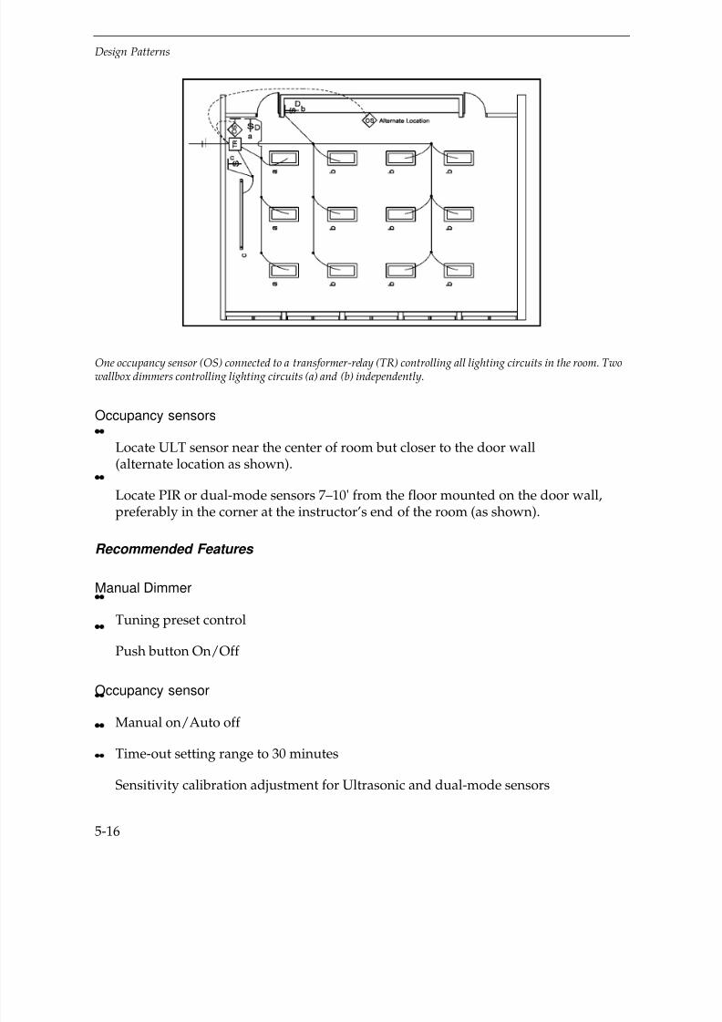
7/21/2019 Lighting Controls Patterns for Design
http://slidepdf.com/reader/full/lighting-controls-patterns-for-design 116/299
Design Patterns
5-16
One occupancy sensor (OS) connected to a transformer-relay (TR) controlling all lighting circuits in the room. Twowallbox dimmers controlling lighting circuits (a) and (b) independently.
Occupancy sensors
Locate ULT sensor near the center of room but closer to the door wall(alternate location as shown).
Locate PIR or dual-mode sensors 7–10' from the floor mounted on the door wall,preferably in the corner at the instructor’s end of the room (as shown).
Recommended Features
Manual Dimmer
Tuning preset control
Push button On/Off
Occupancy sensor
Manual on/Auto off
Time-out setting range to 30 minutes
Sensitivity calibration adjustment for Ultrasonic and dual-mode sensors

7/21/2019 Lighting Controls Patterns for Design
http://slidepdf.com/reader/full/lighting-controls-patterns-for-design 117/299
Design Patterns
5-17
Recommended Settings
Set occupancy sensor time-out setting in the medium range (10–15 minutes)to reduce the inconvenience of “false-offs.”
Design Considerations
Control all lighting circuits in the room using one transformer-relay connected to theoccupancy sensor control.
If daylighting is available, consider using a photosensor connected to a local mastercontroller.
Conference Rooms
Side View
Top View

7/21/2019 Lighting Controls Patterns for Design
http://slidepdf.com/reader/full/lighting-controls-patterns-for-design 118/299
Design Patterns
5-18
Conventional wiring
Conventional Wiring — ExampleFixture Type: Power density: 1.8 W/ft2
Indirect/Direct Pendant Light Level: 50 FC2-F32T8 w/electronic ballasts Switching: Dual level8” x 2’ wall washers (ambient/wall)CF40T5 lamps
Key Problems and Issues
Conference rooms have varied and unpredictable use patterns and lights are typically
left on when the room is not in use. Length of use may vary from 15 minutes to10 hours. They differ by size, location, ambiance, and function served, and thus have awide range of lighting control needs. Different surfaces may need illumination atdifferent times. Conference rooms with access to natural light may be daylighted.Common characteristics of conference rooms include:
Critical visual tasks are performed on several surfaces.
Easy and flexible user-controlled lighting is needed.
Motion by occupants when seated is limited.
A large space is sometimes used by a small group or an individual.
Design illumination levels may range from 30–70 FC. Ceiling heights range from 8–20'and furnishings are generally below 44" except at the perimeter. Conference rooms areoften finished with dark materials and require high lighting power densities.

7/21/2019 Lighting Controls Patterns for Design
http://slidepdf.com/reader/full/lighting-controls-patterns-for-design 119/299
Design Patterns
5-19
Best Control Strategies
Occupancy Responsive
Manual Dimming
Combined Controls
Conventional Wiring
Common fixture types
Common fixture types are 2' x 4' and 2' x 2' direct fluorescent luminaries with parabolicreflectors and indirect and indirect/direct pendant fluorescent fixtures. Incandescent,compact fluorescent, or low-voltage quartz halogen fixtures on tracks or recessed in theceiling may be used for accent, task, or wall display illumination.
Switching Systems
Ambient lighting is controlled at the doorway to the space. Special lighting such as wallwashers is controlled on separate switch circuits, either at the door or near the area being illuminated.
Conference Rooms – Occupancy Responsive – Occupancy Sensor
Application and Savings
Nearly all conference rooms are ideal candidates for occupancy sensor controls. Lightsare often left on all day although the room may only be occupied 20–50% of the time bydifferent users. Sensor type is determined by room area and ceiling height. Lightingenergy savings range from 40–70%. Due to the diversity of use, lighting energy savingsoccur during times of both on- and off-peak building electrical use.
Savings

7/21/2019 Lighting Controls Patterns for Design
http://slidepdf.com/reader/full/lighting-controls-patterns-for-design 120/299
Design Patterns
5-20
Control Devices
Occupancy Sensor
Ultrasonic ceiling sensors or dual-mode sensors work well in medium to largeconference rooms — 350–750 ft2. Dual-mode sensors reduce “false-offs” and“false-ons.”
Passive infrared sensors work well in smaller spaces when the sensor has a clear lineof sight to all areas of activity.
For very small conference rooms — 100–150 ft2 — a wallbox device may be adequate
(either PIR or ULT).
Device Locations
Mount ULT sensors on the ceiling in the center of the space near wall with doors(alternate location as shown).
Locate PIR or dual-mode sensors in the corner above the door (as shown).
Caution:
Do not point PIR or dual-mode sensors out the door.
One occupancy sensor (OS) and one transformer-relay (TR) controls both the ambient lighting and small washerlighting switch legs. Manual override switch (M) connected to transformer-relay (TR).

7/21/2019 Lighting Controls Patterns for Design
http://slidepdf.com/reader/full/lighting-controls-patterns-for-design 121/299
Design Patterns
5-21
Recommended Features
Manual on/Auto off is preferred
Sensitivity calibration adjustment for ultrasonic sensors
Recommended Settings
Set time-out setting in the medium range (10–15 minutes) to reduce “false-offs.”
Calibrate ULT sensors after all furnishings have been installed.
Design Considerations
Control both ambient and special effect or task lighting with the occupancy sensor.
Use transformer-relays (TR) to control fixtures from low-voltage sensor signals.
Provide a manual override switch to turn lights on or off for maximum A/Vpresentation flexibility.
Conference Rooms – Manual Dimming – Wallbox Dimmer
Wireless Remote Dimmer
Application and Savings
Manual dimming control is necessary in many conference rooms to vary light levels forviewing A/V presentations or for normal work. Wall-mounted switching devices varyfrom single dimmer controls to multi-scene preset control panels. In larger conferencespaces, wireless remote control devices can be used to conveniently adjust light levelsfrom any location. Lighting energy savings will depend on the primary use of the roomand the availability of daylight. Manual dimming control will typically save 20–40% of lighting energy.
Savings

7/21/2019 Lighting Controls Patterns for Design
http://slidepdf.com/reader/full/lighting-controls-patterns-for-design 122/299
Design Patterns
5-22
Control Devices
Wallbox dimmer
Preset multi-scene control panel
Wireless remote dimmer Dimming ballasts that dim down to 1–5% provide the best control for A/V task
requirements.
One wall box dimmer (D) controlling the ambient lighting fixture circuit (with dimming ballasts) and one wallboxdimmer controlling all wall wash fixtures (with dimming ballasts).
Device Locations
Some control at the doorway is necessary for conveniently turning lights on and off when entering or leaving the room.
Opt ions :
Add 3-way wallbox dimming control close to the A/V presentation area to improveaccessibility and to give the potential for greater lighting energy savings.
If a wireless remote controller is used, locate the dimming controller target in aneasily visible location.
Recommended Features
A preset maximum light output setting accomplishes tuning.
Preset multi-scene control panel.

7/21/2019 Lighting Controls Patterns for Design
http://slidepdf.com/reader/full/lighting-controls-patterns-for-design 123/299
Design Patterns
5-23
Design Considerations
Provide separate dimming control for ambient lighting and special wall washing ortask light circuits.
Use preset control panels with three or more independently controlled light circuits.
Make sure that dimmer controls and ballasts are compatible, either from the samemanufacturer or listed as being compatible.
Conference Rooms – Combined Controls – Photosensor, + Occupancy
Sensor, + Wallbox Dimmer
Note: See other Conference Room patterns for further details on sensor locations, features, etc.
Savings
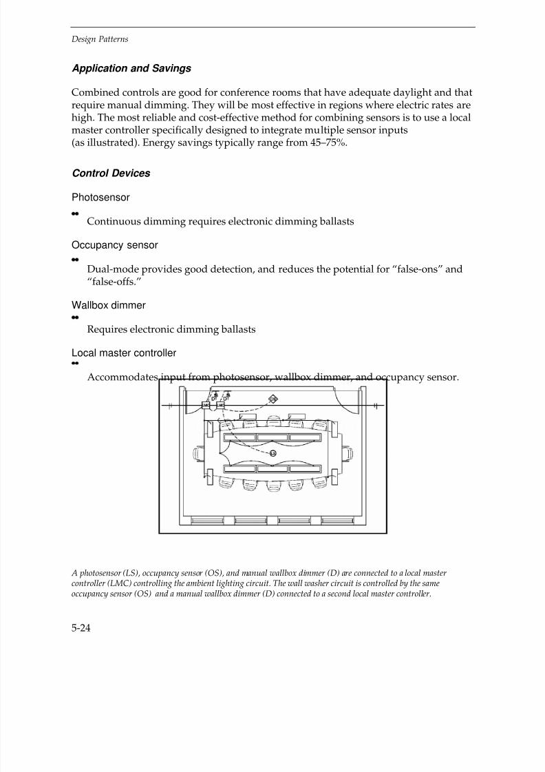
7/21/2019 Lighting Controls Patterns for Design
http://slidepdf.com/reader/full/lighting-controls-patterns-for-design 124/299
Design Patterns
5-24
Application and Savings
Combined controls are good for conference rooms that have adequate daylight and thatrequire manual dimming. They will be most effective in regions where electric rates arehigh. The most reliable and cost-effective method for combining sensors is to use a local
master controller specifically designed to integrate multiple sensor inputs(as illustrated). Energy savings typically range from 45–75%.
Control Devices
Photosensor
Continuous dimming requires electronic dimming ballasts
Occupancy sensor
Dual-mode provides good detection, and reduces the potential for “false-ons” and“false-offs.”
Wallbox dimmer
Requires electronic dimming ballasts
Local master controller
Accommodates input from photosensor, wallbox dimmer, and occupancy sensor.
A photosensor (LS), occupancy sensor (OS), and manual wallbox dimmer (D) are connected to a local mastercontroller (LMC) controlling the ambient lighting circuit. The wall washer circuit is controlled by the sameoccupancy sensor (OS) and a manual wallbox dimmer (D) connected to a second local master controller.

7/21/2019 Lighting Controls Patterns for Design
http://slidepdf.com/reader/full/lighting-controls-patterns-for-design 125/299
Design Patterns
5-25
Device Locations
Photosensor
Typically mount at 1/2–2/3 the depth of the daylight zone.
Occupancy sensor
Do not point out the doorway.
Local master controller
Locate where easily accessed for calibration.
Recommended Features
Photosensor
Closed-loop logic and sensing range from 5 to over 150 FC.
Occupancy sensor
Manual on/Auto off.
Local master controller
With maximum set-point adjustment to accomplish tuning and lumen-maintenance
strategies.
Recommended Settings
Follow manufacturer’s recommendations
Generally:
Set daylight “begin-dimming” setting at the design light level.
Set occupancy sensor time-out setting from 10–15 minutes to reduce the
inconvenience of “false-offs.”
Design Considerations
Use daylight photosensor control for ambient light fixtures only.
Use separate master controllers for spaces with different window orientations.
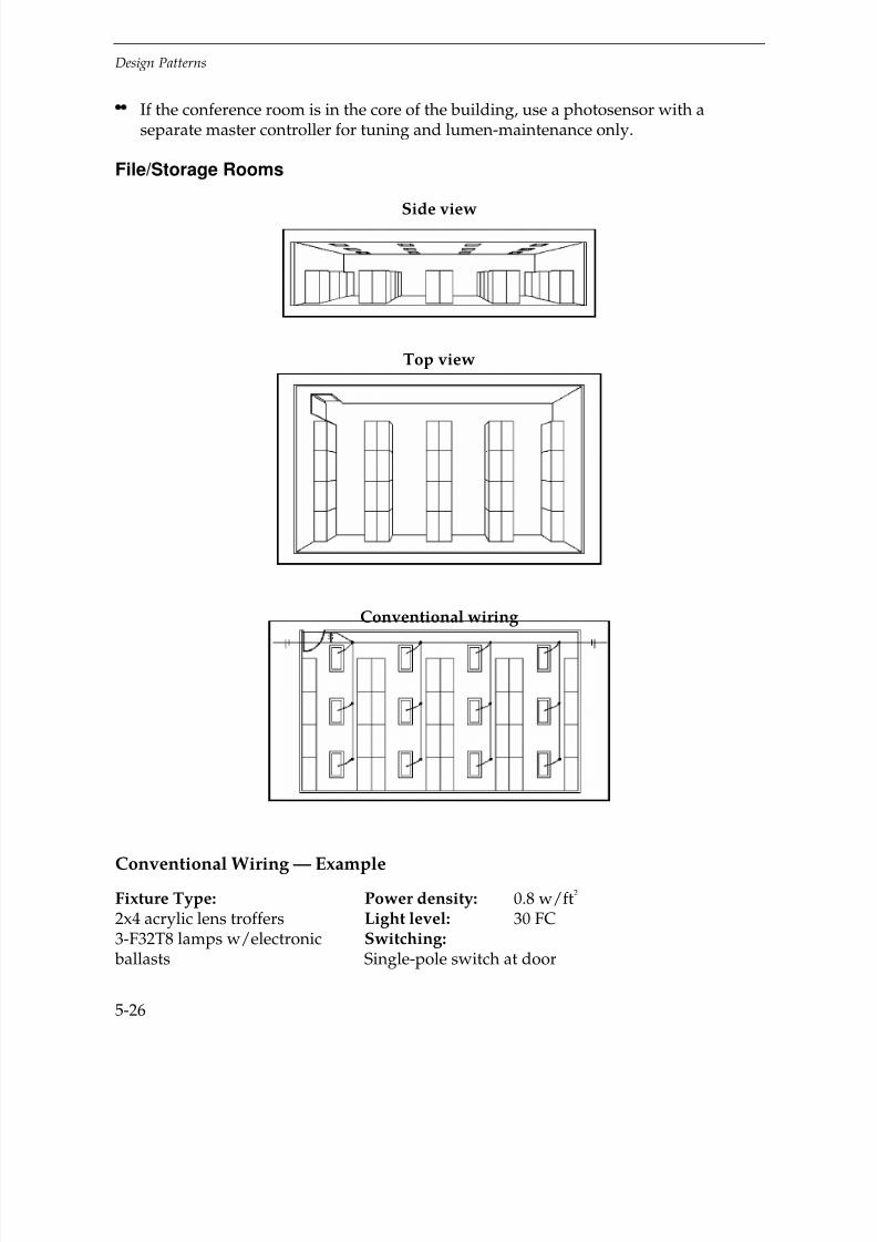
7/21/2019 Lighting Controls Patterns for Design
http://slidepdf.com/reader/full/lighting-controls-patterns-for-design 126/299
Design Patterns
5-26
If the conference room is in the core of the building, use a photosensor with aseparate master controller for tuning and lumen-maintenance only.
File/Storage Rooms
Side view
Top view
Conventional wiring
Conventional Wiring — Example
Fixture Type: Power density: 0.8 w/ft2
2x4 acrylic lens troffers Light level: 30 FC3-F32T8 lamps w/electronic Switching: ballasts Single-pole switch at door
7/21/2019 Lighting Controls Patterns for Design
http://slidepdf.com/reader/full/lighting-controls-patterns-for-design 127/299
Design Patterns
5-27
Key Problems and Issues
File/Storage rooms generally serve long-term storage needs. These spaces are typicallyused intermittently for tasks of relatively short duration. Length of use may range from10 minutes to a few hours. Common characteristics of file/storage rooms include:
Unpredictable periods of use
Varied visual tasks
Moderate user motion
Different users
Floor areas range from 100–1,500 ft2 or larger. Ceiling height is usually 9–12' and shelf and storage cabinets may be as high as 5–7'. In smaller spaces, storage is at the
perimeter; the center of the room is empty or has a work surface at 30" or 42". Largerrooms (as shown) usually have storage isles. File/Storage rooms are frequently locatedin the core of the building.
Best Control Strategies
Occupancy Responsive
Timing
Conventional Wiring
Fixture Types
In rooms with finished ceilings, basic fixtures include 2- and 3-lamp fluorescentrecessed fixtures with acrylic lenses. In rooms with unfinished (open) ceilings, strip orindustrial fluorescent fixtures are common. Light levels range from20–70 FC depending on the type of storage and visual task requirements.
Switching Systems
A single pole wall switch at the door controlling all lights in the space is most common.

7/21/2019 Lighting Controls Patterns for Design
http://slidepdf.com/reader/full/lighting-controls-patterns-for-design 128/299
Design Patterns
5-28
File/Storage Rooms – Occupancy Responsive – Occupancy Sensor
Application and Savings
Occupancy sensor control is good for most file/storage rooms that are usedinfrequently and for short periods. Lights tend to be left on all day due to the diversityof users and the enclosed nature of the space. Occupancy sensor type and placement isdependent on storage height and room layout. Energy savings range from 35–65%.
Control Devices
Occupancy Sensor
Use ultrasonic (ULT) or audible/microphonic ceiling sensors in spaces with highshelving.
Use passive infrared (PIR) sensors in smaller filing/storage rooms where the centerof the room is open and high shelving is located around the perimeter.
Device Locations
Follow the manufacturer’s recommendations for the specific device.
Generally:
Spaces greater than 800 ft2 with aisle shelving near the ceiling will typically require
more than one sensor.
Savings
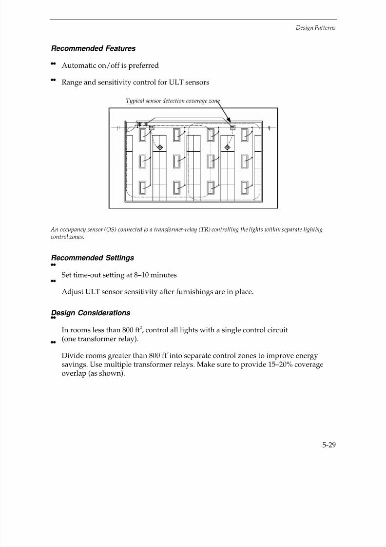
7/21/2019 Lighting Controls Patterns for Design
http://slidepdf.com/reader/full/lighting-controls-patterns-for-design 129/299
Design Patterns
5-29
Recommended Features
Automatic on/off is preferred
Range and sensitivity control for ULT sensors
An occupancy sensor (OS) connected to a transformer-relay (TR) controlling the lights within separate lightingcontrol zones.
Recommended Settings
Set time-out setting at 8–10 minutes
Adjust ULT sensor sensitivity after furnishings are in place.
Design Considerations
In rooms less than 800 ft2, control all lights with a single control circuit
(one transformer relay).
Divide rooms greater than 800 ft2 into separate control zones to improve energysavings. Use multiple transformer relays. Make sure to provide 15–20% coverage
overlap (as shown).
Typical sensor detection coverage zone

7/21/2019 Lighting Controls Patterns for Design
http://slidepdf.com/reader/full/lighting-controls-patterns-for-design 130/299
Design Patterns
5-30
File/Storage Rooms – Timing – Electronic Wallbox Timer, Mechanical Timer
Application and Savings
Use timers for file/storage rooms that are used infrequently for short periods.
Lights are often left on because users don’t feel responsible for the space. Timers arecost-effective and may be preferable to occupancy sensors where the storage space isopen to heavily-used circulation aisles. Energy savings range from 35–65%.
Control Devices
Electronic Timer
Automatically turns lights off after an adjustable preset time. Digital controlprovides silent operation.
Mechanical Timer
Uses a twist dial that winds a spring to set the period of time the lighting circuit willremain open.
Device Locations
Replaces a standard wall switch by the door.
To improve energy savings in large storage rooms, have multiple timers controllingdifferent areas (as shown).
Savings

7/21/2019 Lighting Controls Patterns for Design
http://slidepdf.com/reader/full/lighting-controls-patterns-for-design 131/299
Design Patterns
5-31
A timer control (either electronic or mechanical) is connected to the lighting circuit. An optional timer control isalso shown controlling the two rows of lights near the back of the room separately.
Recommended Features
Adjustable default time-out setting
LED readout
Simple “temporary” manual override of default time-out setting to accommodateoccasional longer usage periods.
Simple Manual Off
Recommended Settings
Set an electronic timer’s time-out setting for the typical amount of time the space isused, generally 10–15 minutes.
Design Considerations
Make sure the device is rated to operate with electronic ballasts.
Make sure the device is rated for the lighting circuit voltage.
To reduce the inconvenience of lights turning off while the space is occupied,provide an emergency light near the timer control.
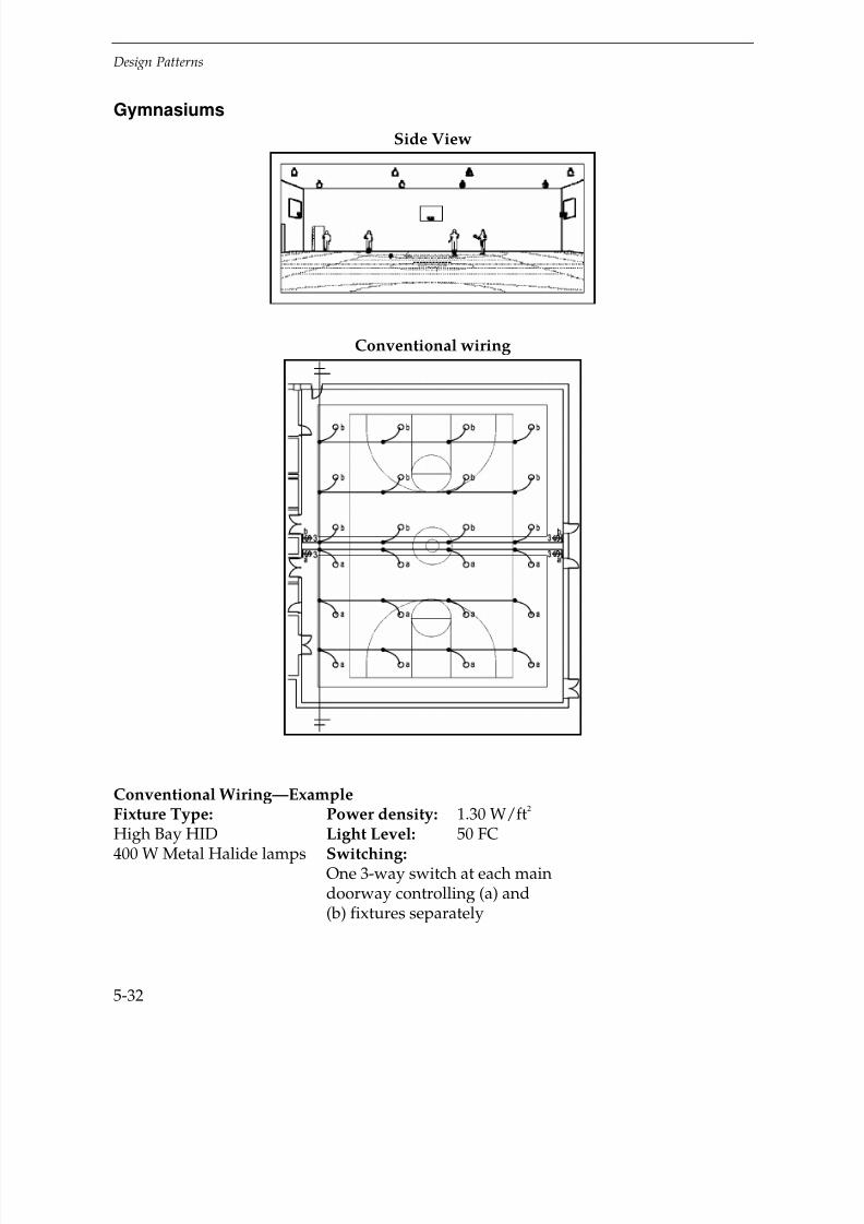
7/21/2019 Lighting Controls Patterns for Design
http://slidepdf.com/reader/full/lighting-controls-patterns-for-design 132/299
Design Patterns
5-32
Gymnasiums
Side View
Conventional wiring
Conventional Wiring—ExampleFixture Type: Power density: 1.30 W/ft2
High Bay HID Light Level: 50 FC400 W Metal Halide lamps Switching:
One 3-way switch at each maindoorway controlling (a) and(b) fixtures separately

7/21/2019 Lighting Controls Patterns for Design
http://slidepdf.com/reader/full/lighting-controls-patterns-for-design 133/299
Design Patterns
5-33
Key Problems and Issues
The usage and occupancy patterns for gymnasiums vary by the type of institutionwhere the gymnasium is located. Elementary and high school gyms may have fairlycontinuous use during normal school hours, whereas usage for gyms in private health
clubs tends to be discontinuous. Nearly all gym activities involve lots of occupantmovement. Common occupancy characteristics for gymnasiums include:
Scheduled, continuous or discontinuous occupancy patterns
Substantial occupant motion
Minimal user responsibility to control lighting
Gymnasiums are located both on the perimeter and in the interior of buildings.Most have ceiling heights ranging from 20–30'. Gyms vary in size from single court
layouts of under 3,200 ft2
to multiple courts of over 10,000 ft2
that have provisions forcurtain/folding wall dividers and movable bleachers for spectators. Gymnasiums withskylights or windows near the top of the walls may be good candidates for daylightingcontrol.
Best Control Strategies
Occupancy Responsive
Conventional Wiring
Common fixture types
HID sources are the predominate fixture system for gymnasiums due to the highceilings and generally high light level requirements. Metal halide systems are the mostpopular due to their good color rendering characteristics. Ballast systems that allow bi-level light output are sometimes installed in cases where higher light levels arerequired for video recording sessions and a lower light level for normal conditions.
Switching Systems
Conventional switching usually has a wall switch located at the main doors. Formultiple court configurations, separate switch legs controlling each court area aresometimes used.

7/21/2019 Lighting Controls Patterns for Design
http://slidepdf.com/reader/full/lighting-controls-patterns-for-design 134/299
Design Patterns
5-34
Gymnasiums – Occupancy Responsive – Occupancy Sensor
Application and Savings
Gymnasiums that have discontinuous occupancy patterns, long hours of operation,
and minimal daylight potential are cost-effective candidates for occupancy sensorcontrol due to the high connected lighting load that is typical for this space type.Multiple sensors connected in parallel are normally required to provide adequatedetection coverage. Lighting energy savings usually ranges from 20–40%.
Control Devices
Occupancy Sensor
Passive Infrared sensors work well when there are no hanging objects that could
block coverage. Dual-mode sensors can normally detect all gymnasium activity — coverage is not
blocked by hanging objects.
Ultrasonic sensors can also work well, check with manufacturer regarding coverageand ceiling height application.
Device Locations
Mount PIR or dual-mode sensors on the wall 10' from the floor.
Very little coverage overlap is needed due to the high level of activity andmovement in the space.
Sensors can be ceiling mounted but they are much more difficult to access for finetuning of the sensor settings.
Savings
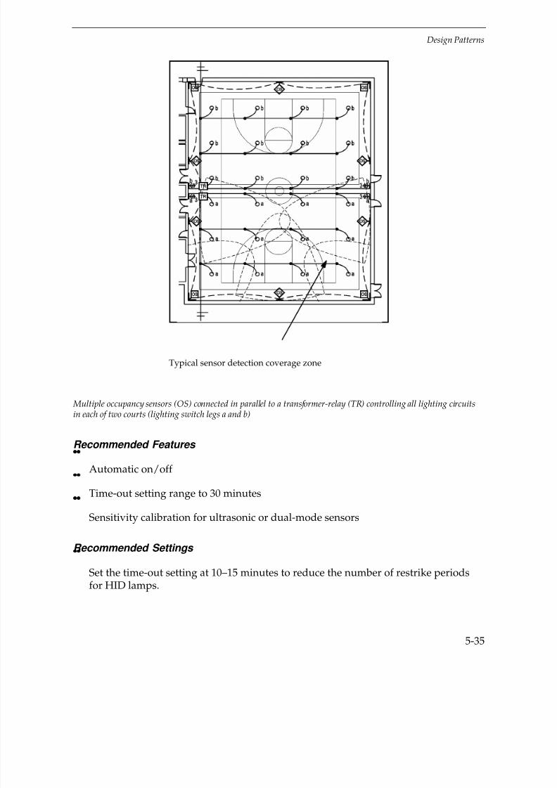
7/21/2019 Lighting Controls Patterns for Design
http://slidepdf.com/reader/full/lighting-controls-patterns-for-design 135/299
Design Patterns
5-35
Multiple occupancy sensors (OS) connected in parallel to a transformer-relay (TR) controlling all lighting circuitsin each of two courts (lighting switch legs a and b)
Recommended Features
Automatic on/off
Time-out setting range to 30 minutes
Sensitivity calibration for ultrasonic or dual-mode sensors
Recommended Settings
Set the time-out setting at 10–15 minutes to reduce the number of restrike periodsfor HID lamps.
Typical sensor detection coverage zone
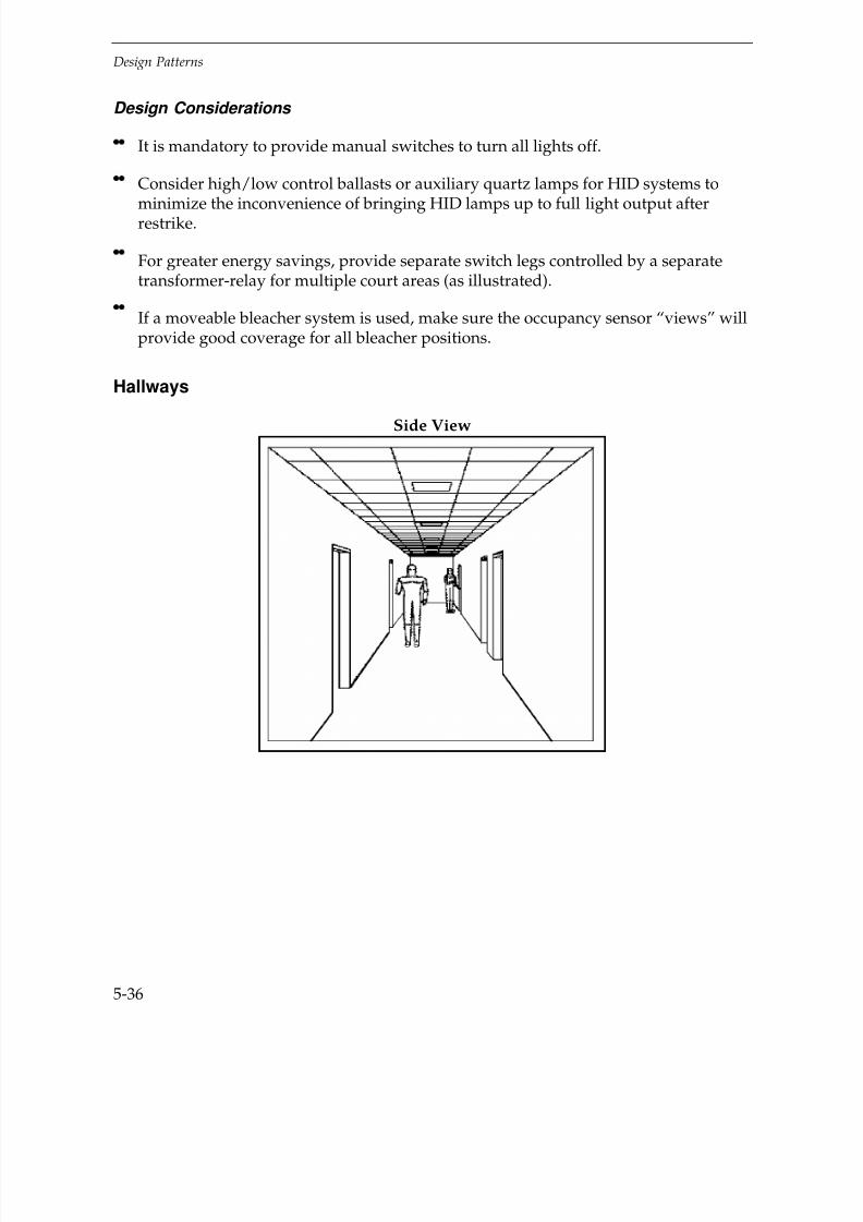
7/21/2019 Lighting Controls Patterns for Design
http://slidepdf.com/reader/full/lighting-controls-patterns-for-design 136/299
Design Patterns
5-36
Design Considerations
It is mandatory to provide manual switches to turn all lights off.
Consider high/low control ballasts or auxiliary quartz lamps for HID systems to
minimize the inconvenience of bringing HID lamps up to full light output afterrestrike.
For greater energy savings, provide separate switch legs controlled by a separatetransformer-relay for multiple court areas (as illustrated).
If a moveable bleacher system is used, make sure the occupancy sensor “views” willprovide good coverage for all bleacher positions.
Hallways
Side View

7/21/2019 Lighting Controls Patterns for Design
http://slidepdf.com/reader/full/lighting-controls-patterns-for-design 137/299
Design Patterns
5-37
Conventional wiring
Key Problems and Issues
The occupancy patterns for hallways vary widely by building type and business
operation. Accurate assessment of the usage for a given circulation path is critical fordetermining which lighting control strategy will be most effective and appropriate.Usage may be predictable or unpredictable and heavy or light. Common characteristicsfor hallways include:
High level of occupant motion
Long narrow spaces
Non-critical visual tasks
Minimal user control responsibility
Hallways are located at both the perimeter and core of a building. They range from4–16' wide and may curve or turn corners. Perimeter hallways and stairways are easilydaylit since they are narrow and seldom require shading devices. Although lightingpower densities are typically lower in corridors than most other spaces, they canaccount for 15–25% of a building's total square footage, which provides the opportunityfor significant lighting energy savings.
Conventional Wiring—ExampleFixture Type:2x2 parabolic troffers3 – F17T8 lamps w/electronic ballasts
Power Density: 0.80 W/Ft2
Light Level: 15 FCSwitching: In secure panel box
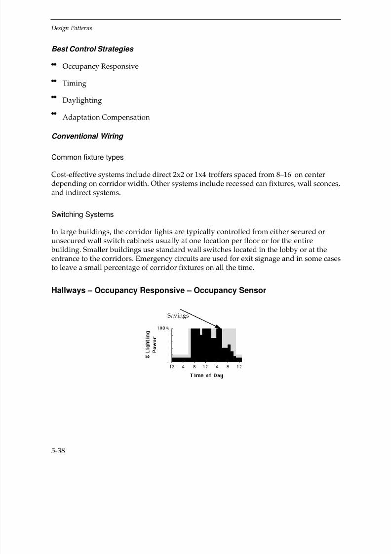
7/21/2019 Lighting Controls Patterns for Design
http://slidepdf.com/reader/full/lighting-controls-patterns-for-design 138/299
Design Patterns
5-38
Best Control Strategies
Occupancy Responsive
Timing
Daylighting
Adaptation Compensation
Conventional Wiring
Common fixture types
Cost-effective systems include direct 2x2 or 1x4 troffers spaced from 8–16' on centerdepending on corridor width. Other systems include recessed can fixtures, wall sconces,and indirect systems.
Switching Systems
In large buildings, the corridor lights are typically controlled from either secured orunsecured wall switch cabinets usually at one location per floor or for the entire building. Smaller buildings use standard wall switches located in the lobby or at theentrance to the corridors. Emergency circuits are used for exit signage and in some casesto leave a small percentage of corridor fixtures on all the time.
Hallways – Occupancy Responsive – Occupancy Sensor
Savings
7/21/2019 Lighting Controls Patterns for Design
http://slidepdf.com/reader/full/lighting-controls-patterns-for-design 139/299
Design Pat t erns
5-39
Application and Savings
Occupancy sensors are good in situations where there are long periods (over 1/2 hour)of no occupancy in hallways or on stairs when the building is open. Buildings where
this is typical include elementary schools, auditoriums, and offices with very long hoursof operation. Energy savings may range from 20–40%.
Control Devices
Occupancy Sensor
Use Passive Infrared sensors in hallways where the line of site is unobstructed andexact detection coverage limits are required to reduce “false-ons.”
Use Ultrasonic sensors in hallways and stairways that are completely enclosed andwhere ceilings are below 14'.
Caution:
Don’t use ULT sensors in locations with high air flow through doorways orvestibules.
Device Locations
Center ceiling-mounted sensors in the corridor with the receiver openings pointed
down the corridor.
Locate high-wall or corner-mounted sensors to favor coverage at points of entrysuch as lobby entrances and main doorways. Good overlap of sensor coverage ismandatory.
Recommended Features
Automatic on/off
Time-out setting range to 30 minutes
Sensitivity calibration adjustment for ultrasonic sensors
Sensor design with long linear coverage (50–90')
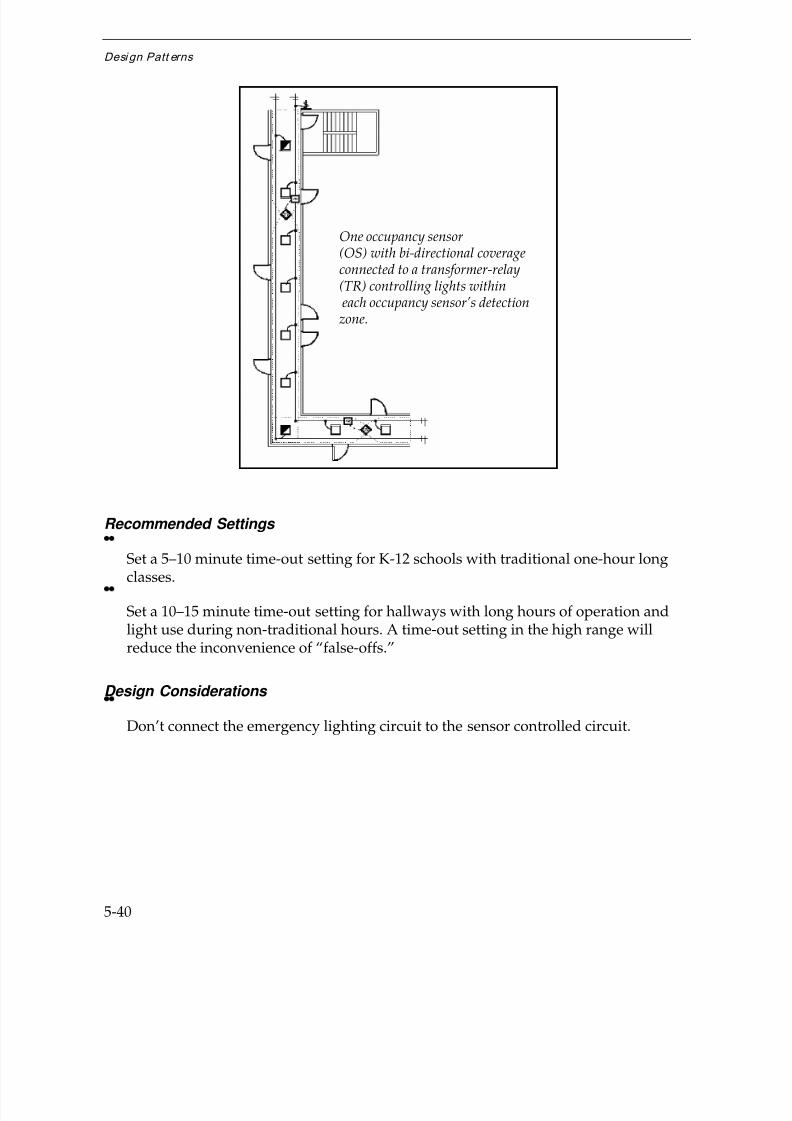
7/21/2019 Lighting Controls Patterns for Design
http://slidepdf.com/reader/full/lighting-controls-patterns-for-design 140/299
Desi gn Patt erns
5-40
Recommended Settings
Set a 5–10 minute time-out setting for K-12 schools with traditional one-hour long
classes.
Set a 10–15 minute time-out setting for hallways with long hours of operation andlight use during non-traditional hours. A time-out setting in the high range willreduce the inconvenience of “false-offs.”
Design Considerations
Don’t connect the emergency lighting circuit to the sensor controlled circuit.
One occupancy sensor(OS) with bi-directional coverageconnected to a transformer-relay(TR) controlling lights within each occupancy sensor’s detection
zone.

7/21/2019 Lighting Controls Patterns for Design
http://slidepdf.com/reader/full/lighting-controls-patterns-for-design 141/299
Design Pat t erns
5-41
Hallways – Timing – Time Clock, Powerline-Carrier System, Relay System,Building Automation System
Application and Savings
Timing is used where occupancy is extremely predictable, which is typical of government, institutional, and retail buildings, where public use is heavy, and wheremanual switching may not be diligent. Time systems range from simple time clockswith relays at sub-panels to Building Automation Systems. Energy savings is normallyat off-peak hours and ranges from 15–30%.
Control Devices
Time Clock
Applicable for small buildings under 20,000 ft2
Powerline-Carrier System
Applicable for existing large buildings
Relay System
Applicable for large buildings
Building Automation System
Applicable for large buildings
Savings

7/21/2019 Lighting Controls Patterns for Design
http://slidepdf.com/reader/full/lighting-controls-patterns-for-design 142/299
Desi gn Patt erns
5-42
Device Locations
Locate time clocks in a secure panel box.
Put Powerline-Carrier and Relay Systems in electrical, maintenance, or
employee-only rooms.
Control Building Automation Systems at a centrally located computer.
Recommended Features
Manual override switch to turn lights on or off near the corridor entrance.
If the building schedule varies within the week, use a 7-day time clock.
If a Building Automation System is installed, consider using time-based features
to control corridor lighting circuits.
Recommended Settings
Set time-off and time-on settings to provide an adequate lag (30–45 minutes) before and after the building is opened and closed.
Time Clock located within secureroom or panel-box connected tonon-emergency hallway lightingcircuits.

7/21/2019 Lighting Controls Patterns for Design
http://slidepdf.com/reader/full/lighting-controls-patterns-for-design 143/299
Design Pat t erns
5-43
Design Considerations
Put corridor and hallway lighting on separate switch legs from other space types.
Separate emergency circuits from time-clock or time-based circuits.
Hallways – Daylighting – Photoswitch, Photosensor
Application and Savings
Daylighting is a good strategy if there is sufficient daylight from windows or skylightsand the building is predominately used in the daytime. Good applications includeskyways, and corridors with regularly spaced, punched or continuous horizontal stripwindows. Due to the lower light level requirements in hallways, lights can generally beswitched off or dimmed to a minimum level during all daylight hours. Energy savings
typically range from 50–80%. Savings usually coincide with peak building electrical use.
Savings

7/21/2019 Lighting Controls Patterns for Design
http://slidepdf.com/reader/full/lighting-controls-patterns-for-design 144/299
Desi gn Patt erns
5-44
Control Devices
Photoswitch
Very cost effective, does not require dimming ballasts
Photosensor
Requires dimming ballasts
Device Locations
Follow manufacturer’s recommendations for the specific device.
Generally:
Mount both photoswitches and photosensors on the ceiling viewing down or onthe near side wall measuring the light level on the wall surface.
If ceiling mounted, locate near center of the corridor.
If indirect lighting is used, make sure the sensor is located below the fixtures.
One photoswitch (PS)
controlling lights withinthe daylight zone.Emergency lighting is on aseparate circuit.

7/21/2019 Lighting Controls Patterns for Design
http://slidepdf.com/reader/full/lighting-controls-patterns-for-design 145/299
Design Pat t erns
5-45
Recommended Features
For Photoswitch control
Adjustable On and Off deadband setting
Adjustable time delay from 1– 5 minutes
Deadband and time delay settings will prevent lights from cycling on and off whenlight levels are close to the setpoint or daylight varies due to clouds.
For Photosensor control
Sensing range from 5 to over 150 FC
Local master controller with maximum and minimum set-point
Closed-loop logic design
Recommended Settings
Follow manufacturer’s recommendations
Generally:
Set time delay at 5 minutes.
For Photoswitch control, set the deadband setting equal to the electric light outputto eliminate cycling.
For Photosensor control, set the begin-dimming setpoint at the design light level.
Design Considerations
Use separate daylighting control circuits and sensors for areas with differentwindow orientations.

7/21/2019 Lighting Controls Patterns for Design
http://slidepdf.com/reader/full/lighting-controls-patterns-for-design 146/299
Desi gn Patt erns
5-46
Hallways – Adaption Compensation – Time Clock,Powerline-Carrier System, Relay System, Building Automation System
Application and Savings
Adaptation compensation is good for hallways operated 24 hours a day where eveningand nighttime operation may require or permit the use of lower light levels, which istypical of hospitals, healthcare facilities, and hospitality buildings. Lighting circuitdesign requires either tandem-wired lamps within a fixture or a provision for everyother fixture to be on a separate circuit. An automatic timing system is then installed toturn off half the lamps during nighttime operation. Time systems range from simpletime clocks with relays at sub-panels to Building Automation Systems. Energy savingsis normally at off-peak hours and ranges from 20–30% percent.
Control Devices
Time Clock
Applicable for small buildings under 20,000 ft2
Powerline-Carrier System
Applicable for existing large buildings
Relay System
Applicable for large buildings
Building Automation System
Applicable for large buildings
Savings

7/21/2019 Lighting Controls Patterns for Design
http://slidepdf.com/reader/full/lighting-controls-patterns-for-design 147/299
Design Pat t erns
5-47
Device Locations
Secure time clocks in the panel box.
Put Powerline-Carrier and Relay Systems in electrical, maintenance, oremployee-only rooms.
Control Building Automation Systems at a centrally located computer.
Recommended Features
Manual override switch to turn lights on or off near the corridor entrance.
If the building schedule varies within the week, use a 7-day time clock.
Astronomic correction for seasonal day length variation.
Recommended Settings
For example, set OFF and ON settings for reduced light level to correspond withvisiting hours in hospitals and healthcare facilities.
Design Considerations
Use switch leg circuits to turn on either 50% or 100% light level. Either wire everyother fixture (as illustrated) or tandem-wire lamps within the fixtures.
Separate emergency circuits from time-clock or time-based circuits (as illustrated).
Time Clock device controlling thelighting circuit wired to every other
fixture in the hallway. Remaining fixtures are connected to the
emergency lighting circuit.

7/21/2019 Lighting Controls Patterns for Design
http://slidepdf.com/reader/full/lighting-controls-patterns-for-design 148/299
Desi gn Patt erns
5-48
Laboratories
Side view
Top view
Conventional wiring
Conventional Wiring—Example
Fixture Type: Power density: 1.80 W/ft2
2x4 acrylic lens troffers Light level: 75 FC3 – F32T8 lamps Switching: 3-way switchesw/electronic ballasts control all lights

7/21/2019 Lighting Controls Patterns for Design
http://slidepdf.com/reader/full/lighting-controls-patterns-for-design 149/299
Design Pat t erns
5-49
Key Problems and Issues
The size, function, and occupancy patterns for laboratories vary significantly byinstitution from small, single-purpose spaces used occasionally by a few, though oftendifferent, workers, to large, multi-purpose spaces operated for long hours by many
users. Laboratories are located both at the perimeter and the core of a building andrange in size from 150 to over 2,000 ft
2. Task areas include desks, apparatus benches,
and fume hoods. Tasks include reading, computer work, and making detailedobservations using a variety of scientific equipment. Common operating characteristicsfor laboratories include:
Open (available for use) for long hours
Non-continuous actual use
Moderate levels of occupant motion
Accurate assessment of the tasks and occupancy characteristics for a laboratory iscritical for determining which lighting control strategy will be most effective.
Best Control Strategies
Occupancy Responsive
Manual Dimming
Daylighting
Combined Controls
Conventional Wiring
Common fixture types
Typical fixture systems include direct 3- and 4-lamp fluorescent 2x4 acrylic lens trofferswith electronic ballasts. Fixture spacing ranges from 50-70 ft
2 per fixture generally
providing 60-80 FC of ambient illumination. Other systems include direct/indirectfixtures with many variations of occupant installed task lighting to suit required deskand bench work.
Switching Systems
Small labs usually have a single wall switch near the door or opening to the spacecontrolling all the ambient lighting. Larger labs typically have multiple switch locationswith all the ambient lighting circuits controlled from each location. Tasks lights areindividually controlled.

7/21/2019 Lighting Controls Patterns for Design
http://slidepdf.com/reader/full/lighting-controls-patterns-for-design 150/299
Desi gn Patt erns
5-50
Laboratories – Occupancy Responsive – Occupancy Sensor
Application and Savings
Occupancy sensor control is good for large laboratories that are operated for long hourswith periods of light and infrequent use, typical of academic and some private companylabs. Occupancy sensor control is also good for small, single-function spaces that havemultiple users. Spaces that are operated continuously are generally not good candidates(e.g., medical/clinical labs). Lighting savings typically varies from 20–50%.
Control Devices
Occupancy Sensor
Use dual-mode sensors for rooms with multiple apparatuses and fume hoods
Use ultrasonic ceiling sensors for spaces with high shelving, benches, or other highfurniture. They are not as applicable in spaces where high velocity supply air tofume hoods could cause “false-ons.”
Use passive infrared sensors in open spaces where their “view” is unobstructedand precise coverage limits are required (e.g., to ensure that the main aisle is notcovered, as shown in the design pattern).
Savings

7/21/2019 Lighting Controls Patterns for Design
http://slidepdf.com/reader/full/lighting-controls-patterns-for-design 151/299
Design Pat t erns
5-51
One occupancy sensor (OS) and one transformer-relay (TR) for each of three overlapping detection zones; lights inmain aisle and next to side walls are not controlled.
Device Locations
Good overlap of sensor coverage is mandatory. The design pattern shows individualsensor control of separate lab zones. In each case, the coverage zones overlap thefixtures controlled by the sensor by one row of fixtures to maintain adequatefar-field illumination for adjacent work areas.
Caution:
Inadequate sensor overlap will turn lights off too close to occupied areas.
Recommended Features
Automatic on/off
Time out setting range to 30 minutes
Sensitivity calibration adjustment for ultrasonic sensors
Recommended Settings
Set the time-out setting in the high range (15–20 minutes) to reduce theinconvenience of “false-offs.”
Adjust the sensitivity calibration for ULT sensors after all furnishings are in place.If work stations are rearranged or altered, it is a good idea to verify and adjustsensor coverage.

7/21/2019 Lighting Controls Patterns for Design
http://slidepdf.com/reader/full/lighting-controls-patterns-for-design 152/299
Desi gn Patt erns
5-52
Design Considerations
Small separate lighting zones will give the most energy savings because it is oftenthe case that not all work zones are occupied at the same time.
Do not connect lighting in the main circulation aisle to the occupancy sensor.
In large lab rooms with multiple work zones, leave the lights next to walls off thesensor circuit to maintain adequate far-field luminance in the space.
Provide manual switches to turn lights off also.
Laboratories – Manual Dimming – Wallbox Dimmer,Wireless Remote Dimmer
Application and Savings
For use in multi-purpose laboratories where tasks require variations in ambient lightinglevels.
It may be convenient to use a wireless remote control device in lab spaces wherefrequent adjustment of light levels are required. Lighting energy savings will varydepending on the primary use of the room and the availability of daylight. Manualdimming control can typically save from 20–40% of lighting energy.
Savings
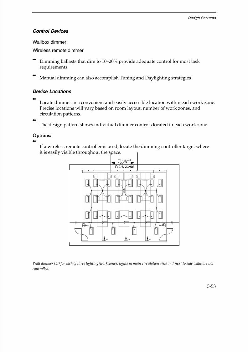
7/21/2019 Lighting Controls Patterns for Design
http://slidepdf.com/reader/full/lighting-controls-patterns-for-design 153/299
Design Pat t erns
5-53
Control Devices
Wallbox dimmer
Wireless remote dimmer
Dimming ballasts that dim to 10–20% provide adequate control for most taskrequirements
Manual dimming can also accomplish Tuning and Daylighting strategies
Device Locations
Locate dimmer in a convenient and easily accessible location within each work zone.Precise locations will vary based on room layout, number of work zones, andcirculation patterns.
The design pattern shows individual dimmer controls located in each work zone.
Options:
If a wireless remote controller is used, locate the dimming controller target whereit is easily visible throughout the space.
Wall dimmer (D) for each of three lighting/work zones; lights in main circulation aisle and next to side walls are not
controlled.
TypicalWork Zone
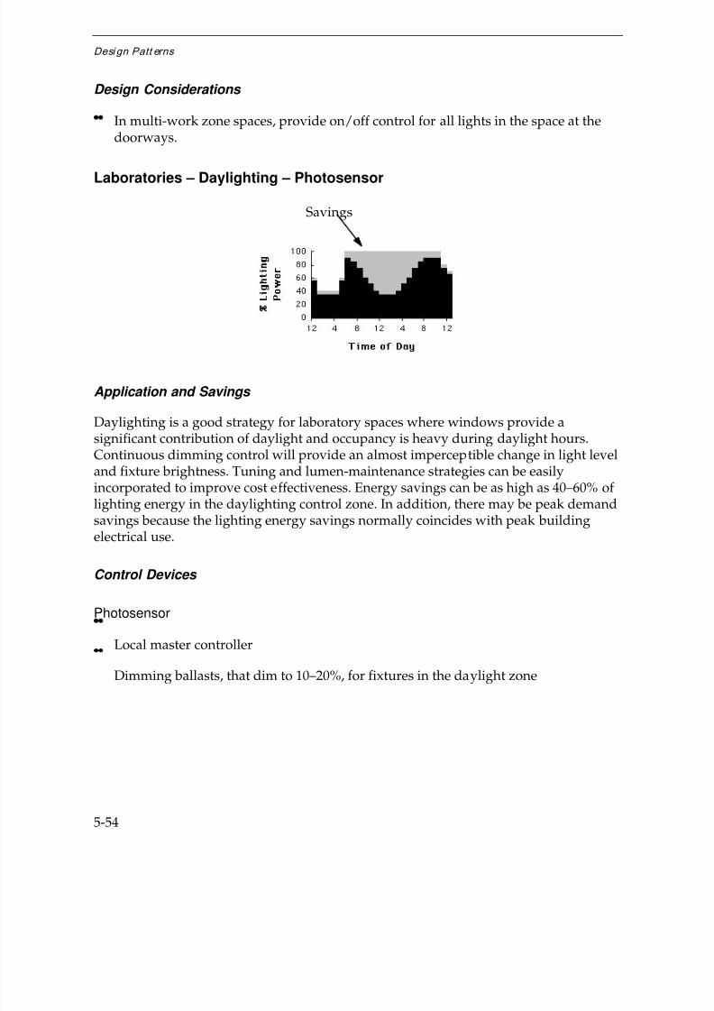
7/21/2019 Lighting Controls Patterns for Design
http://slidepdf.com/reader/full/lighting-controls-patterns-for-design 154/299
Desi gn Patt erns
5-54
Design Considerations
In multi-work zone spaces, provide on/off control for all lights in the space at thedoorways.
Laboratories – Daylighting – Photosensor
Application and Savings
Daylighting is a good strategy for laboratory spaces where windows provide asignificant contribution of daylight and occupancy is heavy during daylight hours.Continuous dimming control will provide an almost imperceptible change in light leveland fixture brightness. Tuning and lumen-maintenance strategies can be easilyincorporated to improve cost effectiveness. Energy savings can be as high as 40–60% of lighting energy in the daylighting control zone. In addition, there may be peak demand
savings because the lighting energy savings normally coincides with peak buildingelectrical use.
Control Devices
Photosensor
Local master controller
Dimming ballasts, that dim to 10–20%, for fixtures in the daylight zone
Savings

7/21/2019 Lighting Controls Patterns for Design
http://slidepdf.com/reader/full/lighting-controls-patterns-for-design 155/299
Design Pat t erns
5-55
Caution:
Using stepped rather than continuous dimming daylighting sensors is not advisable because a more abrupt change in light level may be detrimental to the critical visualtasks performed in a lab.
Device Locations
Follow the manufacturer's recommendations for the specific device.
Generally:
Mount the sensor on the ceiling viewing down or on the side wall measuring thelight level on the wall surface.
Locate the sensor at 1/2–2/3 the depth of the daylighting zone back from thewindow.
Photosensor (LS) controls two rows of lights (w/dimming ballasts) near windows and is connected to wall-mountedlocal master controller (LMC) for adjustments and future connection of other devices.
Recommended Features
Sensing range from 5 to over 150 FC
Local master controller with maximum and minimum light level set-points
Closed-loop logic design
Daylighting Control Zone
7/21/2019 Lighting Controls Patterns for Design
http://slidepdf.com/reader/full/lighting-controls-patterns-for-design 156/299
Desi gn Patt erns
5-56
Options:
Allows automatic incorporation of tuning and lumen-maintenance strategies.
Allows addition of manual dimming at little added first cost.
Recommended Settings
Follow manufacturer's recommendations
Generally:
Set maximum light level at design footcandles.
Set minimum light level to make the space feel adequately lighted, usually20–30% of full light output.
Design Considerations
Control lights that are parallel to the window within a depth of 2–2.5 times thewindow head height.
If the window head height is greater than 10', consider using two daylighting zonescontrolled by different photosensors. Use the first zone to control the two rows of lights nearest to the windows and the second zone to control lights further backfrom the window.
Use separate daylighting control circuits and sensors for areas with differentwindow orientations.
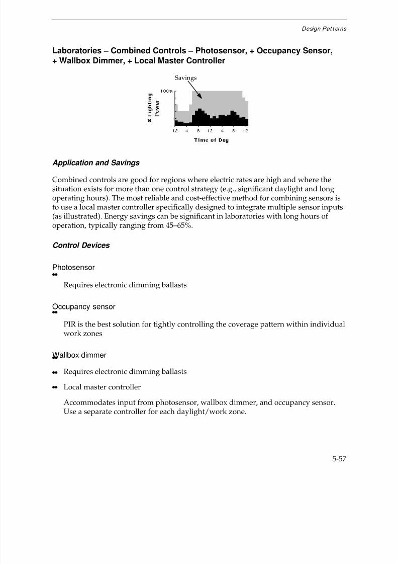
7/21/2019 Lighting Controls Patterns for Design
http://slidepdf.com/reader/full/lighting-controls-patterns-for-design 157/299
Design Pat t erns
5-57
Laboratories – Combined Controls – Photosensor, + Occupancy Sensor,+ Wallbox Dimmer, + Local Master Controller
Application and Savings
Combined controls are good for regions where electric rates are high and where the
situation exists for more than one control strategy (e.g., significant daylight and longoperating hours). The most reliable and cost-effective method for combining sensors isto use a local master controller specifically designed to integrate multiple sensor inputs(as illustrated). Energy savings can be significant in laboratories with long hours of operation, typically ranging from 45–65%.
Control Devices
Photosensor
Requires electronic dimming ballasts
Occupancy sensor
PIR is the best solution for tightly controlling the coverage pattern within individualwork zones
Wallbox dimmer
Requires electronic dimming ballasts
Local master controller
Accommodates input from photosensor, wallbox dimmer, and occupancy sensor.Use a separate controller for each daylight/work zone.
Savings
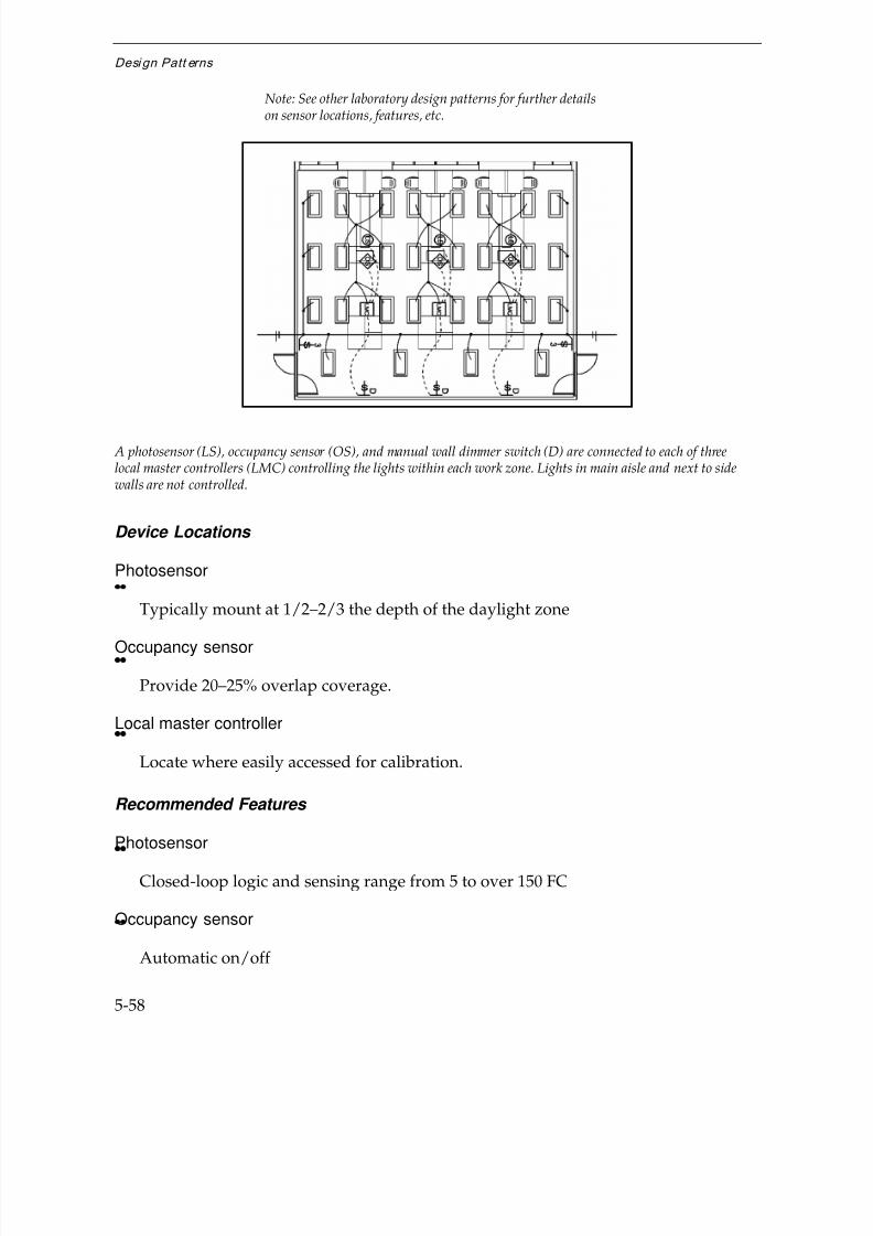
7/21/2019 Lighting Controls Patterns for Design
http://slidepdf.com/reader/full/lighting-controls-patterns-for-design 158/299
Desi gn Patt erns
5-58
A photosensor (LS), occupancy sensor (OS), and manual wall dimmer switch (D) are connected to each of threelocal master controllers (LMC) controlling the lights within each work zone. Lights in main aisle and next to sidewalls are not controlled.
Device Locations
Photosensor
Typically mount at 1/2–2/3 the depth of the daylight zone
Occupancy sensor
Provide 20–25% overlap coverage.
Local master controller
Locate where easily accessed for calibration.
Recommended Features
Photosensor
Closed-loop logic and sensing range from 5 to over 150 FC
Occupancy sensor
Automatic on/off
Note: See other laboratory design patterns for further detailson sensor locations, features, etc.
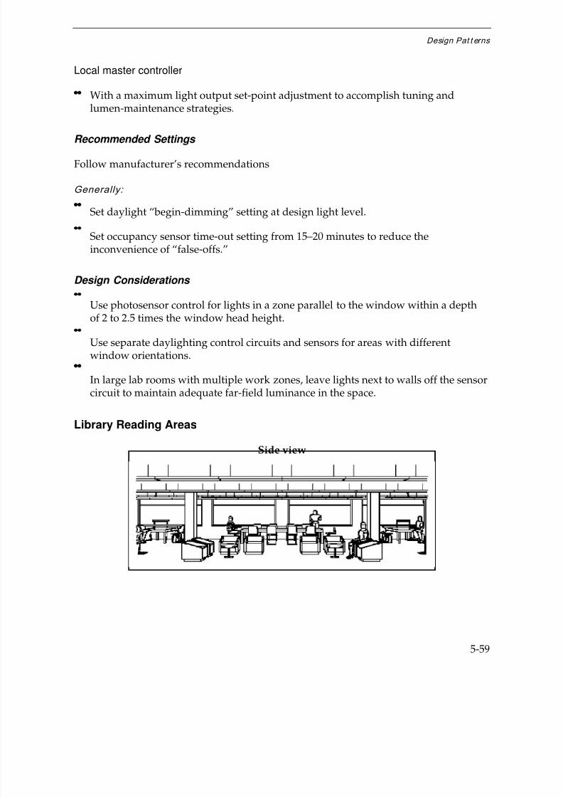
7/21/2019 Lighting Controls Patterns for Design
http://slidepdf.com/reader/full/lighting-controls-patterns-for-design 159/299
Design Pat t erns
5-59
Local master controller
With a maximum light output set-point adjustment to accomplish tuning andlumen-maintenance strategies.
Recommended Settings
Follow manufacturer’s recommendations
Generally:
Set daylight “begin-dimming” setting at design light level.
Set occupancy sensor time-out setting from 15–20 minutes to reduce theinconvenience of “false-offs.”
Design Considerations
Use photosensor control for lights in a zone parallel to the window within a depthof 2 to 2.5 times the window head height.
Use separate daylighting control circuits and sensors for areas with differentwindow orientations.
In large lab rooms with multiple work zones, leave lights next to walls off the sensorcircuit to maintain adequate far-field luminance in the space.
Library Reading Areas
Side view

7/21/2019 Lighting Controls Patterns for Design
http://slidepdf.com/reader/full/lighting-controls-patterns-for-design 160/299
Desi gn Patt erns
5-60
Top view
Conventional wiring
Conventional Wiring — ExampleFixtureType: Power density: 1.80 W/ft2
Direct/Indirect Light level: Variable 15 to 70 FCPendant-mounted Switching: in maintenance room2- F32T8 lampsw/electronic ballasts
Key Problems and Issues
Library reading areas are used for both casual, short-term reading and focused study atcarrels or desks for long periods. Reading areas also have large variations in occupancypatterns. Length of use may range from 10 minutes to 8 hours.
Reading/study areas are frequently located at the perimeter of libraries with access tonatural light, but larger study spaces may extend far from the windows. Informalreading areas are occasionally treated as low brightness lounge areas. Desks and carrels

7/21/2019 Lighting Controls Patterns for Design
http://slidepdf.com/reader/full/lighting-controls-patterns-for-design 161/299
Design Pat t erns
5-61
are increasingly used with notebook computers. Common characteristics of readingareas include:
Undefined periods of peak use
Used for intense visual tasks
Limited motion by occupants when seated
Reading areas range from 200–2000 ft2or larger. Ceilings heights range from 8–20',
and furnishings are generally less than 44" tall.
Best Control Strategies
Occupancy Responsive
Timing
Daylighting
Conventional Wiring
Common Fixture Types
Basic fixtures include direct/indirect, pendant-mounted fixtures or 2x4 parabolictroffers. Design illumination levels range from 30–40 FC for indirect fixtures to 70 FCwith direct fixtures. In academic libraries, task lighting is also common within studycarrels or at reading desks.
Switching Systems
Ambient lighting is typically controlled at a central, secure location near the maincirculation desk in small libraries or in a building maintenance room in large libraries.Task lighting is generally controlled at the task location.

7/21/2019 Lighting Controls Patterns for Design
http://slidepdf.com/reader/full/lighting-controls-patterns-for-design 162/299
Desi gn Patt erns
5-62
Library Reading Areas – Occupancy Responsive – Occupancy Sensor
Application and Savings
Occupancy sensor control is good for library reading areas that are used infrequently.Heavily used reading areas that are close to the main entrance or near popular book
collections are typically not good spaces for this strategy. Lighting energy savingsgenerally range from 30–50% depending on the frequency of use.
Control Devices
Occupancy Sensor
Use passive infrared or dual-mode sensors when obstructions (e.g. carrels) are lowand coverage limits need to be tightly controlled to reduce “false ons” from adjacentcirculation areas.
Use ultrasonic sensors for self-contained spaces.
Device Locations
Good overlap of sensor coverage is mandatory. In the design pattern, the coveragezones overlap the fixtures controlled by the sensor by one row of fixtures tomaintain adequate far-field illumination for the occupants in adjacent reading areas.
Cautions:
Inadequate sensor overlap will turn lights off too close to occupied areas.
Avoid detecting motion in main circulation aisles.
Savings

7/21/2019 Lighting Controls Patterns for Design
http://slidepdf.com/reader/full/lighting-controls-patterns-for-design 163/299
Design Pat t erns
5-63
One occupancy sensor (OS) and one transformer-relay (TR) for each of four overlapping detection zones.Row of lights in circulation zone not controlled.
Recommended Features
Automatic on/off
Time out setting range to 30 minutes
Sensitivity calibration adjustment for ultrasonic sensors
Recommended Settings
Set the time-out setting in the high range (15–25 minutes) to reduce theinconvenience of “false-offs.”
Set the sensitivity calibration after all furnishings are in place.
Design Considerations
Small separate lighting zones will give the most energy savings because it is oftenthe case that not all reading areas are occupied at the same time.
Use transformer-relays (TR) to control fixtures from low-voltage sensor signals.
Typical sensor detection coverage zone
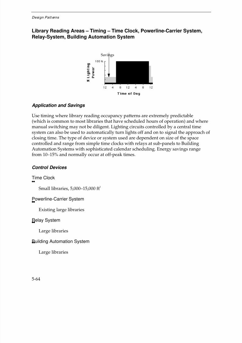
7/21/2019 Lighting Controls Patterns for Design
http://slidepdf.com/reader/full/lighting-controls-patterns-for-design 164/299
Desi gn Patt erns
5-64
Library Reading Areas – Timing – Time Clock, Powerline-Carrier System,Relay-System, Building Automation System
Application and Savings
Use timing where library reading occupancy patterns are extremely predictable(which is common to most libraries that have scheduled hours of operation) and wheremanual switching may not be diligent. Lighting circuits controlled by a central timesystem can also be used to automatically turn lights off and on to signal the approach of closing time. The type of device or system used are dependent on size of the spacecontrolled and range from simple time clocks with relays at sub-panels to BuildingAutomation Systems with sophisticated calendar scheduling. Energy savings rangefrom 10–15% and normally occur at off-peak times.
Control Devices
Time Clock
Small libraries, 5,000–15,000 ft2
Powerline-Carrier System
Existing large libraries
Relay System
Large libraries
Building Automation System
Large libraries
Savings
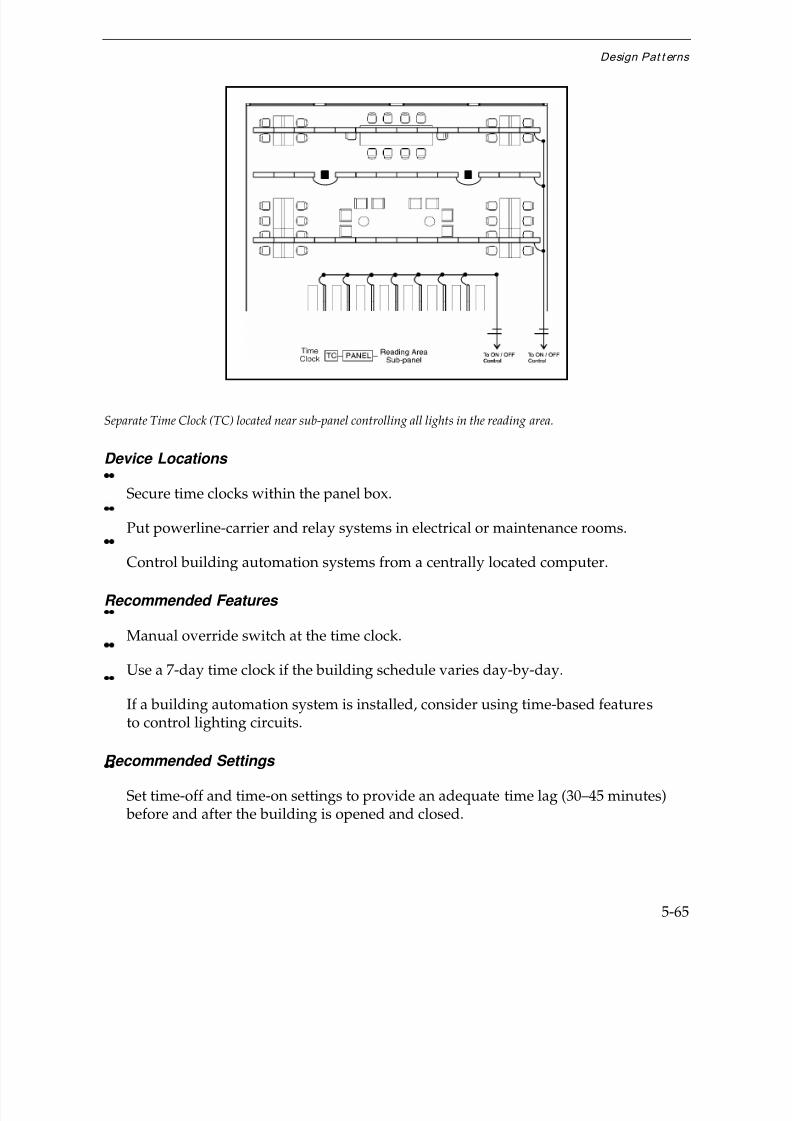
7/21/2019 Lighting Controls Patterns for Design
http://slidepdf.com/reader/full/lighting-controls-patterns-for-design 165/299
Design Pat t erns
5-65
Separate Time Clock (TC) located near sub-panel controlling all lights in the reading area.
Device Locations
Secure time clocks within the panel box.
Put powerline-carrier and relay systems in electrical or maintenance rooms.
Control building automation systems from a centrally located computer.
Recommended Features
Manual override switch at the time clock.
Use a 7-day time clock if the building schedule varies day-by-day.
If a building automation system is installed, consider using time-based featuresto control lighting circuits.
Recommended Settings
Set time-off and time-on settings to provide an adequate time lag (30–45 minutes) before and after the building is opened and closed.
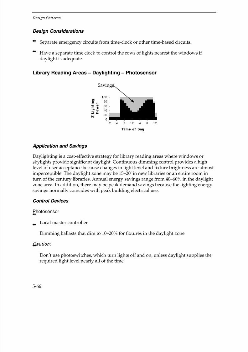
7/21/2019 Lighting Controls Patterns for Design
http://slidepdf.com/reader/full/lighting-controls-patterns-for-design 166/299
Desi gn Patt erns
5-66
Design Considerations
Separate emergency circuits from time-clock or other time-based circuits.
Have a separate time clock to control the rows of lights nearest the windows if
daylight is adequate.
Library Reading Areas – Daylighting – Photosensor
Application and Savings
Daylighting is a cost-effective strategy for library reading areas where windows orskylights provide significant daylight. Continuous dimming control provides a highlevel of user acceptance because changes in light level and fixture brightness are almostimperceptible. The daylight zone may be 15–20' in new libraries or an entire room in
turn of the century libraries. Annual energy savings range from 40–60% in the daylightzone area. In addition, there may be peak demand savings because the lighting energysavings normally coincides with peak building electrical use.
Control Devices
Photosensor
Local master controller
Dimming ballasts that dim to 10–20% for fixtures in the daylight zone
Caution:
Don’t use photoswitches, which turn lights off and on, unless daylight supplies therequired light level nearly all of the time.
Savings

7/21/2019 Lighting Controls Patterns for Design
http://slidepdf.com/reader/full/lighting-controls-patterns-for-design 167/299
Design Pat t erns
5-67
Photosensor (LS) controlling two rows of lights (w/dimming ballasts) near windows connected to local mastercontroller (LMC) for adjustments of light level and future connection of other devices.
Device Locations
Follow manufacturer’s recommendations for the specific device.
Generally:
Mount sensor on the ceiling viewing down or on the near side wall measuring the
light level on the wall surface.
Locate at 1/2–2/3 the depth of the daylighting zone back from the window.
If there is indirect lighting, make sure the sensor is located below the fixtures.
Recommended Features
Sensing range from 5 to over 150 FC
Local master controller with maximum and minimum set-points.
Closed-loop logic design to automatically incorporate tuning andlumen-maintenance strategies.

7/21/2019 Lighting Controls Patterns for Design
http://slidepdf.com/reader/full/lighting-controls-patterns-for-design 168/299
Desi gn Patt erns
5-68
Recommended Settings
Follow manufacturers’ recommendations
Generally:
Set maximum light level at design FC
Set minimum light level to make the space feel adequately lighted, usually20–30% of full light output.
Design Considerations
Control lights that are parallel to the window within a depth of 2–2.5 times thewindow head height.
If the window head height is greater than 10', consider using two daylighting zonescontrolled by different photosensors. Use the first zone to control the two rows of lights nearest to the windows and the second zone to control lights further backfrom the window.
Use separate daylighting control circuits and sensors for areas with differentwindow orientations.
Library Stacks
Side View

7/21/2019 Lighting Controls Patterns for Design
http://slidepdf.com/reader/full/lighting-controls-patterns-for-design 169/299
Design Pat t erns
5-69
Top view
Conventional wiring
Conventional Wiring—ExampleFixture Type: Power density: 1.2 W/ft
2
Direct louvered “stack light” Light level: 40 FC1 lamp fluorescent Switching: at sub-panelw/electronic ballastsPendant-mounted
Key Problems and Issues
Library stack areas have unpredictable occupancy patterns. Stacks containing popularitems, typically located near the main desk, may be occupied continuously, while somestacks of research materials in university libraries will have very infrequent use. Hoursof operation vary from 8-12 hours a day for public libraries to 24 hours a day at someuniversity libraries.

7/21/2019 Lighting Controls Patterns for Design
http://slidepdf.com/reader/full/lighting-controls-patterns-for-design 170/299
Desi gn Patt erns
5-70
Stack areas are often located in the core of the building away from natural light.However, some public lending libraries will permit daylighting of non-critical books(e.g., popular and children’s collections). Duration of use is typically between 5 and20 minutes. Common characteristics of stack areas include:
Defined periods of peak usage
Moderate motion by occupants while browsing
Greater movement at the ends of the stacks than within the stack aisles
Stack aisles are typically ringed by study carrels or informal reading areas. Stack areasrange from 500-2000 ft2 or larger with aisles ranging in length from 15-40’. Ceilingheights range from 8-20’; 9-12’ is very common. Bookshelf heights range from 4-7’.
Best Control Strategies
Occupancy Responsive
Timing
Conventional Wiring
Common Fixture Types
Louvered fluorescent strip fixtures mounted on the stacks or pendant-hung from theceiling provide good lighting for vertical surfaces. Design illumination levels rangefrom 30-70 FC. Fixtures are typically located over the center of the aisle. Other systemsinclude direct fluorescent luminaries with parabolic or prismatic lenses, indirectpendant fluorescent fixtures, or specially designed shelf lighting mounted to the stacks.
Switching Systems
General lighting is usually controlled at a central, secure location. This may be in the building maintenance room or at the main desk.

7/21/2019 Lighting Controls Patterns for Design
http://slidepdf.com/reader/full/lighting-controls-patterns-for-design 171/299
Design Patterns
5-71
Library Stacks – Occupancy Responsive – Occupancy Sensor
Application and Savings
Occupancy sensor control is good for stack areas that are used infrequently. Stacks
containing popular collections, usually located near the main desk, that are frequentlyoccupied are not good candidates for this pattern. Remotely located stacks that oftenremain unoccupied for long periods throughout the day are good candidates forturning off or stepping down lights when no one is present. The effect of turning lightson and off in stacks that are close to reading areas must be considered. Energy savingsrange from 40–70%. If there are many control zones, a reduction in peak electricaldemand is also likely.
Control Devices
Occupancy Sensor
Use passive infrared sensors to provide tight coverage limits within stack aisles.PIR sensor line-of-sight “viewing” works well here.
Ultrasonic sensors are only appropriate where the stacks are enclosed in a separateroom.
Device Locations
Sensor location is based on the length and height of the storage aisle and sensor
coverage pattern.
It is most cost-effective to mount a sensor directly on the luminaire.
The design pattern shows a PIR sensor at each end of a long stack aisle. The lensdesign limits the coverage pattern so that lights turn on reliably when the aisle isentered but coverage is not extended into the cross-aisle, which eliminates
Savings

7/21/2019 Lighting Controls Patterns for Design
http://slidepdf.com/reader/full/lighting-controls-patterns-for-design 172/299
Design Patterns
5-72
“false-ons” from general circulation. If the stack aisle is less than 15–20' long, use onesensor with a coverage pattern in two directions centered in the middle of the aisleor one sensor at the main entry point adjusted so as not to detect motion beyond thestack.
Cautions:
Sensor detection coverage extending into general circulation or reading areas willcause numerous “false-ons.”
Verify lens coverage from the manufacturer’s specification.
Two occupancy sensors (OS) for each aisle connected in parallel to one transformer-relay (TR).
Recommended Features
Automatic on/off
Easily adjusted time delay
Recommended Settings
Set time-out setting from 5–10 minutes
When installing multiple sensors, fine tune one sensor to establish mountinglocation and angle, then repeat the settings for the other sensors.
7/21/2019 Lighting Controls Patterns for Design
http://slidepdf.com/reader/full/lighting-controls-patterns-for-design 173/299
Design Patterns
5-73
Design Considerations
Treat each stack aisle as one occupancy sensor control zone.
To reduce the annoyance to nearby reading areas of lights turning off and on,
consider not connecting the first fixture at the end of each stack aisle to theoccupancy sensor control circuit or not controlling the lights in every third row.
Library Stacks – Timing – Electronic Wallbox Timer, Mechanical Timer
Application and Savings
Timers are good for stack areas that are used infrequently. Timers may also be a cost-effective alternative to difficult occupancy sensor coverage applications (e.g., stackswith a low shelf height or stacks that are more open to general circulation and reading
areas). Energy savings can range from 40–70%, occurring during both on- and off-peakelectrical use periods.
Control Devices
Electronic Timer
Automatically turns lights off after an adjustable preset time. Digital controlprovides silent operation.
Mechanical Timer
Uses a twist dial or preset button that winds a spring to set the period of time thelighting circuit will remain open. Noise from the mechanical clock may be a problemin quiet spaces.
Savings

7/21/2019 Lighting Controls Patterns for Design
http://slidepdf.com/reader/full/lighting-controls-patterns-for-design 174/299
Design Patterns
5-74
Device Locations
Mount timers at stack ends at a height that meets Americans with Disabilities Act(ADA) regulations.
Make sure the timer is easily identified.
Long stack aisles may require a 3-way timer switch at both ends of the stack.
Recommended Features
Adjustable default time-out setting
Simple “temporary” manual override of default time-out setting to accommodateoccasional longer periods of use.
Simple Manual Off
One timer (TM) controlling the lights in two aisles mounted at the end with the heaviest traffic (reading area side).
An optional 3-way timer control for convenience is shown at the opposite end of the aisle.
Recommended Settings
Set the time-out setting on electronic timers to the typical stack use time, generally10–15 minutes.
7/21/2019 Lighting Controls Patterns for Design
http://slidepdf.com/reader/full/lighting-controls-patterns-for-design 175/299
Design Patterns
5-75
Design Considerations
One switch circuit for every two aisles works well (as illustrated).
One switch per single aisle will yield greater energy savings but cost more.
Consider not connecting the first fixture at the end of each aisle to the timer control.
Cautions:
Make sure the device is rated to operate with electronic ballasts and the lightingcircuit voltage.
When designing the timer location and wiring, remember that the stacks may berearranged in the future.
Library Stacks – Timing – Time Clock, Powerline-Carrier System,Relay System, Building Automation System
Application and Savings
Use timing where library reading occupancy patterns are extremely predictable(which is common to most libraries that have scheduled hours of operation) and wheremanual switching may not be diligent. Lighting circuits controlled by a central timesystem can also be used to automatically turn lights off and on to signal the approach of closing time. The type of device or system used are dependent on the size of the spacecontrolled and range from simple time clocks with relays at sub-panels to BuildingAutomation Systems with sophisticated calendar scheduling. Energy savings rangefrom 15–20% and normally occur at off-peak times.
Savings

7/21/2019 Lighting Controls Patterns for Design
http://slidepdf.com/reader/full/lighting-controls-patterns-for-design 176/299
Design Patterns
5-76
Control Devices
Time Clock
Small libraries, 5,000–15,000 ft2
Powerline-Carrier System
Existing large libraries
Relay System
Large libraries
Building Automation System
Large libraries
Device Locations
Secure time clocks within the panel box.
Put powerline-carrier and relay systems in electrical or maintenance rooms.
Control building automation systems from a centrally located computer.
Separate time clock (TC) located near the sub-panel controlling all lights in the stack areas.

7/21/2019 Lighting Controls Patterns for Design
http://slidepdf.com/reader/full/lighting-controls-patterns-for-design 177/299
Design Patterns
5-77
Recommended Features
Manual override switch at the time clock.
Use a 7-day time clock if the building schedule varies day-by-day.
If a building automation system is installed, consider using time-based features tocontrol lighting circuits.
Recommended Settings
Set time-off and time-on settings to provide an adequate time lag (30–45 minutes) before and after the building is opened and closed.
Design Considerations
Keep emergency lighting circuits separate from time-clock or other time-based
circuits.
Open Offices
Key Problems and Issues
Open offices are large spaces where groups of people work. The key problem is how tocontrol the ambient light for a group of people successfully. Generally each officeworker has his/her own work station containing a desk, cabinets, shelves, andcomputer. It is common for work stations to be separated by partitions 4' to 6' high.Common occupancy characteristics for open offices include:
Heavy use during traditional hours (8–5)
Light use outside of traditional hours
Moderate level of occupant motion
Minimal user responsibility to control ambient lighting
Open office areas are located both at the perimeter and the core of a building and rangein size from a few desks in 250 ft2 to an entire floor of a building. Perimeter offices withadequate window areas provide good opportunities for daylighting control.
Best Control Strategies
Occupancy Responsive
Daylighting
Combined Controls

7/21/2019 Lighting Controls Patterns for Design
http://slidepdf.com/reader/full/lighting-controls-patterns-for-design 178/299
Design Patterns
5-78
Side view
Top view
Conventional wiring
Conventional Wiring—ExampleFixture Type: Power density: 1.10 W/ft2
2x4 parabolic troffer Light level: 50 FC3-F32T8 lamps Switching: Permeter (a) andw/electronic ballasts Core (b) switch legs

7/21/2019 Lighting Controls Patterns for Design
http://slidepdf.com/reader/full/lighting-controls-patterns-for-design 179/299
Design Patterns
5-79
Conventional Wiring
Common fixture types
Basic fixture systems include direct 3-lamp fluorescent 2x4 parabolic troffers with
3-lamp electronic ballasts. Fixture density ranges from 70–90 ft2
per fixture generallyproviding from 40–60 FC of average illumination. Other systems include task/ambient,direct/indirect, and 2-lamp 1x4 and 2x2 troffers.
Switching Systems
In small open offices the lights are controlled from a single wall switch near the door oropening to the space. Larger office areas typically have multiple switches at onelocation controlling all the lighting circuits.
Open Offices – Occupancy Responsive – Occupancy Sensor
Application and Savings
Occupancy sensor control is good for open plan offices that have long total hours of operation (10–12 hr/day or more) but have fewer users outside of traditional officehours. Without controls, cleaning crews or one worker may keep lights on in largeunoccupied areas for long periods. Large open office areas can be divided into zonescontrolled by occupancy sensors so that lights are turned down or off in areas thataren’t occupied. Most of the lighting energy will be saved outside of traditionalworking hours since it is unusual for all workers within a coverage zone to be absent
during regular working hours. Energy savings typically range from 15–25%.
Savings

7/21/2019 Lighting Controls Patterns for Design
http://slidepdf.com/reader/full/lighting-controls-patterns-for-design 180/299
Design Patterns
5-80
Control Devices
Occupancy Sensor
Use ultrasonic sensors for spaces with high partitions. In most cases, 6–8 workstations can be sensed from one ultrasonic sensor.
Use passive-infrared or dual-mode sensors when partitions are low or not presentand coverage limits need to be tightly controlled to reduce “false ons.”
Use personal-workstation occupancy sensors in spaces with task lights and multipleelectrical devices.
Device Locations
Good overlap of sensor coverage is mandatory. The design pattern shows two sensorscontrolling two separate switch legs. The coverage zones overlap the fixtures controlled by one row to maintain adequate far-field illumination for the work stations in adjacentareas.
Cautions:
Inadequate sensor overlap will turn lights off too close to occupied work stations.
Avoid detecting motion in main circulation aisles.
Recommended Features
Automatic on/off
Time-out setting range to 30 minutes
Recommended Settings
Set the time-out setting in the high range, (15–25 minutes) to reduce theinconvenience of “false-offs.”
Adjust the sensitivity calibration after all furnishings are in place. When workstations are rearranged or altered, it is a good idea to verify and adjust sensorcoverage.
7/21/2019 Lighting Controls Patterns for Design
http://slidepdf.com/reader/full/lighting-controls-patterns-for-design 181/299
Design Patterns
5-81
Design Considerations
Small separate lighting zones will give the most energy savings because it is oftenthe case that not all work zones are occupied at the same time.
Use transformer-relays (TR) to control fixtures from low-voltage sensor signals.
Provide manual switches to turn lights off also .
One occupancy sensors (OS) and one transformer-relay (TR) for each of two overlapping detection zones.
Open Offices – Daylighting – Photosensor
Typical sensor coverage zone
Savings

7/21/2019 Lighting Controls Patterns for Design
http://slidepdf.com/reader/full/lighting-controls-patterns-for-design 182/299
Design Patterns
5-82
Application and Savings
Daylighting is a cost-effective strategy for perimeter open office areas where windowsor skylights provide a significant contribution of daylight and occupancy is heavyduring daylight hours. Continuous dimming control provides an almost imperceptible
change in light level and fixture brightness. The 15–20'-wide perimeter daylight zone inmost office buildings can be as much as 30–60% of total floor area. Lighting energy usesavings range from 30–60%.
Control Devices
Photosensor
Local master controller
Dimming ballasts that dim to 10–20% for fixtures in daylight zone (a)
Caution:
Photoswitch sensors, which turn lights on or off, are not advisable for the officeenvironment unless daylight supplies the required light level nearly all of the timeto minimize switching.
Device Locations
Follow the manufacturer’s recommendations for the specific device.
Generally:
Mount sensor on the ceiling viewing down or on the near side wall measuring thelight level on the wall surface.
Locate sensor at 1/2–2/3 the depth of the daylighting zone back from the window.
If indirect lighting is used, make sure sensor is located below the fixture.

7/21/2019 Lighting Controls Patterns for Design
http://slidepdf.com/reader/full/lighting-controls-patterns-for-design 183/299
Design Patterns
5-83
Photosensor (LS) controlling two rows of lights (with dimming ballasts) near windows, connected to local mastercontroller (LMC) for adjustment and future connection to other devices.
Recommended Features
Sensing range from 5 to over 150 FC
Local master controller with maximum and minimum set-point
Closed-loop logic design
Options:
Allows automatic incorporation of tuning and lumen-maintenance strategies.
Allows addition of manual dimming at little added first cost.
Recommended Settings
Follow manufacturer’s recommendations
Generally:
Set maximum light level at design FC
Set minimum light level to make the space feel adequately lighted, usually20–30% of full light output.
Typical daylight zone
7/21/2019 Lighting Controls Patterns for Design
http://slidepdf.com/reader/full/lighting-controls-patterns-for-design 184/299
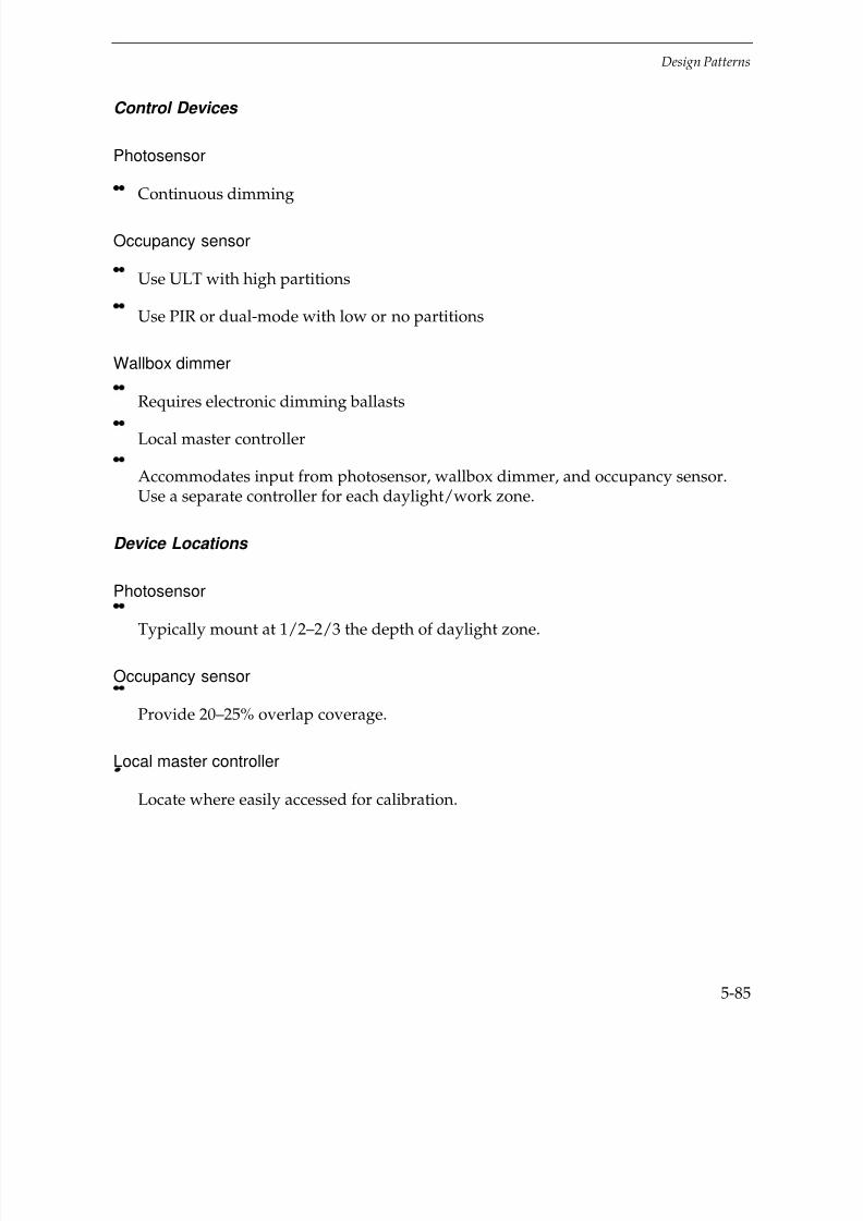
7/21/2019 Lighting Controls Patterns for Design
http://slidepdf.com/reader/full/lighting-controls-patterns-for-design 185/299
Design Patterns
5-85
Control Devices
Photosensor
Continuous dimming
Occupancy sensor
Use ULT with high partitions
Use PIR or dual-mode with low or no partitions
Wallbox dimmer
Requires electronic dimming ballasts
Local master controller
Accommodates input from photosensor, wallbox dimmer, and occupancy sensor.Use a separate controller for each daylight/work zone.
Device Locations
Photosensor
Typically mount at 1/2–2/3 the depth of daylight zone.
Occupancy sensor
Provide 20–25% overlap coverage.
Local master controller
Locate where easily accessed for calibration.

7/21/2019 Lighting Controls Patterns for Design
http://slidepdf.com/reader/full/lighting-controls-patterns-for-design 186/299
Design Patterns
5-86
Note: See office patterns for further details on sensor locations, features, etc.
A photosensor (LS), occupancy sensor (OS), and manual wall dimmer switch (D) are connected to each of two localmaster controllers (LMC) controlling the lights within two separate zones. The photosensor in the core zone (b)
provides for Tuning and Lumen-Maintenance strategies only.
Recommended Features
Photosensor
Closed-loop logic and sensing range from 5 to over 150 FC.
Occupancy sensor
Automatic on/off
Local master controller
With maximum set-point adjustment to accomplish tuning and lumen-maintenancestrategies.

7/21/2019 Lighting Controls Patterns for Design
http://slidepdf.com/reader/full/lighting-controls-patterns-for-design 187/299
Design Patterns
5-87
Recommended Settings
Follow manufacturer’s recommendations
Generally:
Set daylight “begin-dimming” setting at design light level.
Set occupancy sensor time-out setting in the high range (15–25 minutes) to reducethe inconvenience of “false-offs.”
Design Considerations
Use photosensor for daylight control of lights in a zone parallel to the windowwithin a depth of 2–2.5 times the window head height.
Use separate daylighting control circuits and sensors for areas with differentwindow orientations.
In the core zone, use photosensor for tuning and lumen-maintenance (only).This requires a separate local master controller.
Private Offices
Key Problems and Issues
Private Offices are typically small, single-use, single-occupant spaces. It is unlikely thatthe occupancy pattern for most private offices will fit a set schedule. Most work is doneat a desk and involves little movement. Common occupancy characteristics include:
Varied (unscheduled) occupancy patterns
Minimal occupant motion
Few primary task areas
A high requirement for lighting control by the occupant.
Private offices are located at both the perimeter and in the core of a building and rangein size from 100–250 ft2. A private office typically contains a desk, cabinets, shelves, anda computer. Because the space is small, a private office with windows provides anexcellent opportunity for daylighting.

7/21/2019 Lighting Controls Patterns for Design
http://slidepdf.com/reader/full/lighting-controls-patterns-for-design 188/299
Design Patterns
5-88
Side view
Top view
Conventional wiring
Conventional Wiring—ExampleFixture Type: Power density: 1.50 W/ft
2
2x4 parabolic troffer Light level: 50FC3 – 32T8 lamps Switching: wall switch at doorw/electronic ballasts

7/21/2019 Lighting Controls Patterns for Design
http://slidepdf.com/reader/full/lighting-controls-patterns-for-design 189/299
Design Patterns
5-89
Key Problems and Issues
Private Offices are typically small, single-use, single-occupant space. It is unlikely thatthe occupancy pattern for most private offices will fit a set schedule. Most work is doneat a desk and involves little movement. Common occupancy characteristics include:
Varied (unscheduled)occupancy patterns
Minimal occupant motion
Few primary task areas
A high requirement for lighting control by the occupant.
Private offices are located at both the perimeter and in the core of a builfing and rangein size from 100-250 ft2. A private office typically contains a desk, cabinets, shelves, and
a computer. Because the space is small, a private office with windows provides anexcellent opportunity for daylighting.
Best Control Strategies
Occupancy Responsive
Daylighting
Combined Controls
Conventional Wiring
Common fixture types
Basic fixture systems include direct 3-lamp fluorescent 2x4 parabolic troffers with3-lamp electronic ballasts. Other systems include task/ambient lighting, direct/indirectfixtures, and 2-lamp 1x4 troffers. Design light levels usually range from 35–70 FC.
Switching Systems
Lights are controlled from a wall switch near the door or opening to the space.Task lights are commonly switched at the fixture.

7/21/2019 Lighting Controls Patterns for Design
http://slidepdf.com/reader/full/lighting-controls-patterns-for-design 190/299

7/21/2019 Lighting Controls Patterns for Design
http://slidepdf.com/reader/full/lighting-controls-patterns-for-design 191/299
Design Patterns
5-91
Wallbox sensor (OS) controlling the ambient lighting circuit.
Wall mount sensor (OS) connected to a transfer-relay (TR) controlling all ambient lights.
Device Locations
Locate wallbox sensors on the same wall as the entrance door on the latch side of thedoor.
Mount ceiling sensors near the center of room over the main desk area.
Locate high-wall sensors in the corner of the room near the main doorway.
Cautions:
Avoid locating the sensor behind a door or potential file cabinet locations.
For PIR sensors, avoid locations where they “view” out the door.

7/21/2019 Lighting Controls Patterns for Design
http://slidepdf.com/reader/full/lighting-controls-patterns-for-design 192/299
Design Patterns
5-92
Recommended Features
Manual on/Auto off
Sensitivity calibration adjustment for ultrasonic sensors
Recommended Settings
Set the time-out setting in the low range (8–10 minutes).
Set the sensitivity calibration after all furnishings are in place.
Design Considerations
Manual on/Auto off control gives the occupant greater control of the space and mayincrease energy savings in rooms with daylight.
Private Offices – Daylighting – Photosensor
Application and Savings
Daylighting is usually a cost-effective strategy for private offices that have windows.Due to the generally narrow room depths, typical commercial window design providessignificant daylight with good uniformity. Continuous dimming control providesalmost imperceptible changes in light level and fixture brightness. The energy savings
potential ranges from 40–70% depending on when the office is used. Maximum energysavings normally coincides with peak building electrical consumption.
Savings
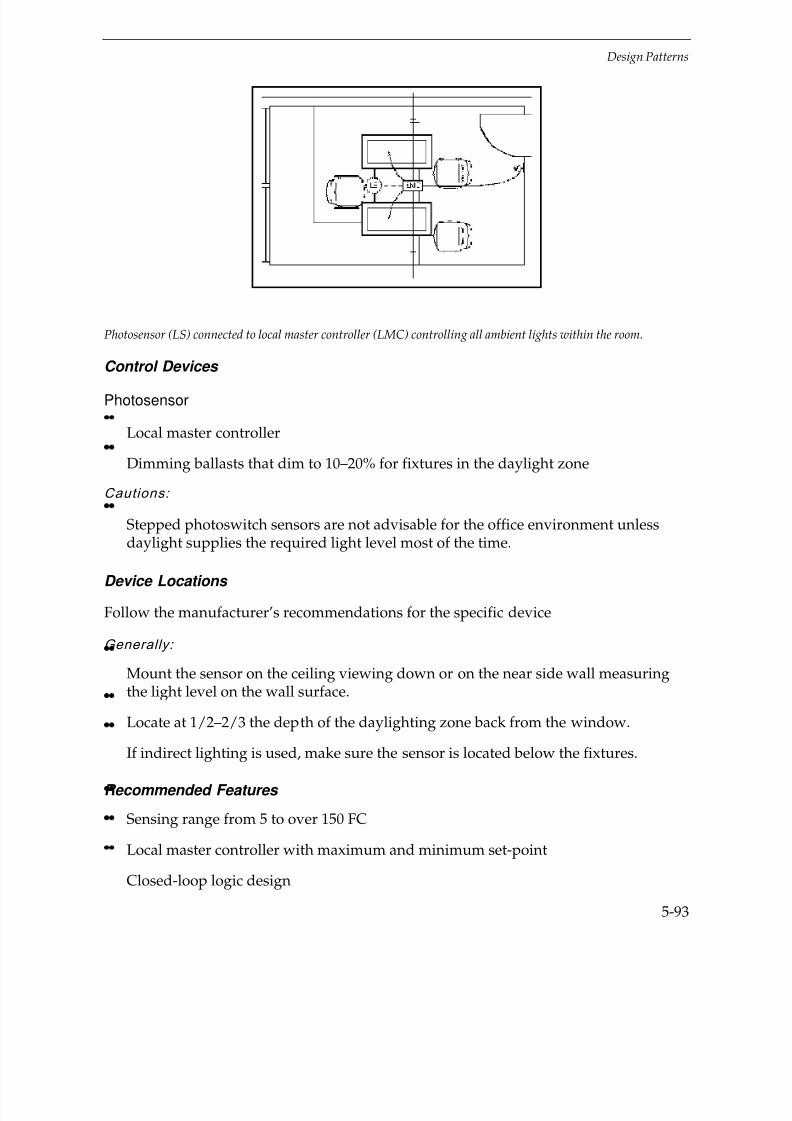
7/21/2019 Lighting Controls Patterns for Design
http://slidepdf.com/reader/full/lighting-controls-patterns-for-design 193/299
Design Patterns
5-93
Photosensor (LS) connected to local master controller (LMC) controlling all ambient lights within the room.
Control Devices
Photosensor
Local master controller
Dimming ballasts that dim to 10–20% for fixtures in the daylight zone
Cautions:
Stepped photoswitch sensors are not advisable for the office environment unlessdaylight supplies the required light level most of the time.
Device Locations
Follow the manufacturer’s recommendations for the specific device
Generally:
Mount the sensor on the ceiling viewing down or on the near side wall measuringthe light level on the wall surface.
Locate at 1/2–2/3 the depth of the daylighting zone back from the window.
If indirect lighting is used, make sure the sensor is located below the fixtures.
Recommended Features
Sensing range from 5 to over 150 FC
Local master controller with maximum and minimum set-point
Closed-loop logic design
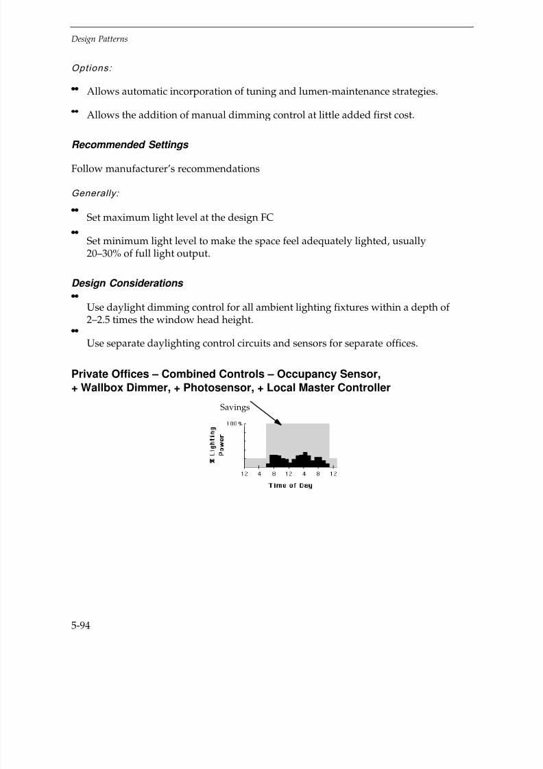
7/21/2019 Lighting Controls Patterns for Design
http://slidepdf.com/reader/full/lighting-controls-patterns-for-design 194/299
Design Patterns
5-94
Options:
Allows automatic incorporation of tuning and lumen-maintenance strategies.
Allows the addition of manual dimming control at little added first cost.
Recommended Settings
Follow manufacturer’s recommendations
Generally:
Set maximum light level at the design FC
Set minimum light level to make the space feel adequately lighted, usually20–30% of full light output.
Design Considerations
Use daylight dimming control for all ambient lighting fixtures within a depth of 2–2.5 times the window head height.
Use separate daylighting control circuits and sensors for separate offices.
Private Offices – Combined Controls – Occupancy Sensor,
+ Wallbox Dimmer, + Photosensor, + Local Master ControllerSavings

7/21/2019 Lighting Controls Patterns for Design
http://slidepdf.com/reader/full/lighting-controls-patterns-for-design 195/299
Design Patterns
5-95
Application and Savings
Combined controls are a cost-effective strategy for regions where electric rates are highand the function and type of office space allow for multiple control strategies. The mostreliable and cost-effective method for combining sensors is to use a local master
controller specifically designed to integrate multiple sensor inputs (as illustrated).Energy savings may range from 45–75%.
Control Devices
Occupancy sensor
Dual-mode sensor provides good sensing detection and reduces the risk of “false-offs” and “false-ons.”
Wallbox dimmer
Requires electronic dimming ballasts
Photosensor
Requires electronic dimming ballasts
Local master controller
Accommodates input from photosensor, wallbox dimmer, and occupancy sensor.
Note: See other private office patterns for further details on sensor locations, features, etc.
Occupancy sensor (OS), photosensor (LS), and manual wallbox dimmer control (D) all connected to a local mastercontroller (LMC) controlling the ambient lighting circuit.
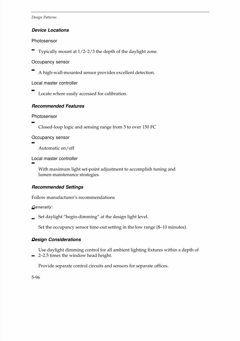
7/21/2019 Lighting Controls Patterns for Design
http://slidepdf.com/reader/full/lighting-controls-patterns-for-design 196/299
Design Patterns
5-96
Device Locations
Photosensor
Typically mount at 1/2–2/3 the depth of the daylight zone.
Occupancy sensor
A high-wall-mounted sensor provides excellent detection.
Local master controller
Locate where easily accessed for calibration.
Recommended Features
Photosensor
Closed-loop logic and sensing range from 5 to over 150 FC
Occupancy sensor
Automatic on/off
Local master controller
With maximum light set-point adjustment to accomplish tuning and
lumen-maintenance strategies.
Recommended Settings
Follow manufacturer’s recommendations
Generally:
Set daylight “begin-dimming” at the design light level.
Set the occupancy sensor time-out setting in the low range (8–10 minutes).
Design Considerations
Use daylight dimming control for all ambient lighting fixtures within a depth of 2–2.5 times the window head height.
Provide separate control circuits and sensors for separate offices.

7/21/2019 Lighting Controls Patterns for Design
http://slidepdf.com/reader/full/lighting-controls-patterns-for-design 197/299
Design Patterns
5-97
Restrooms
Side view
Top view
Conventional wiring
Conventional wiring—ExampleFixture Type: Power density: 0.08 W/ft2
1x4 parabolic troffers Light level: 30 FC2-F32T8 lamps Switching: single pole atw/electric ballasts the doorDownlight fixtures2-CF18T5

7/21/2019 Lighting Controls Patterns for Design
http://slidepdf.com/reader/full/lighting-controls-patterns-for-design 198/299
Design Patterns
5-98
Key Problems and Issues
Public restrooms vary in size and frequency of use. Larger restrooms that serve morepeople are often used more frequently than smaller restrooms. Occupancy may beintermittent or focused between scheduled events. The lights are often left on all night
because they go unnoticed. Common occupancy characteristics include:
Short periods of use
Moderate level of occupant motion
No user responsibility to control lighting
Restrooms are located within the service core of most buildings. Restrooms that do havewindows use translucent glazing that generally does not provide sufficient daylight.They range in size from private, single-user restrooms at 50–65 ft
2 to large public
facilities, common to airports and sports complexes, at over 1,000 ft2
. Public restroomstypically have 6–7'-high partitioned stalls. The need for good illumination is highest infront of the mirrors where tasks include grooming and putting on make-up.
Best Control Strategies
Occupancy Responsive
Conventional Wiring
Common fixture types
Basic fixture systems include 1x4, 2x4, and 2 x2 troffer fixtures with electronic ballasts.Recessed can downlight fixtures with compact fluorescent lamps are also common.
Switching Systems
The lights are controlled from a wall switch near the door or, more typical in largepublic buildings, from a switch accessed by a key.

7/21/2019 Lighting Controls Patterns for Design
http://slidepdf.com/reader/full/lighting-controls-patterns-for-design 199/299
Design Patterns
5-99
Restrooms – Occupancy Responsive – Occupancy Sensor
Application and Savings
Occupancy sensors are good for most public restrooms, except for restrooms in 24-hourfacilities that are used constantly. Sensor layout is dependent on the size of the
restroom. Energy savings range from 40–60%.
Control Devices
Occupancy Sensor
Ultrasonic (ULT) ceiling sensors work well because they can adequately sensemotion within stalls and they are sensitive to small movements; and, since restroomdoors are left closed, there is no sensor detection of movement outside the space tocause “false-ons.”
Passive Infrared (PIR) sensors work best in private, single-user restrooms were theyview the entire space. PIR sensors generally do not provide adequate sensing inmulti-stall restrooms.
Dual mode or audible/microphonics sensors provide a high degree of detectioncoverage reducing the risks of “false-offs.”
Savings
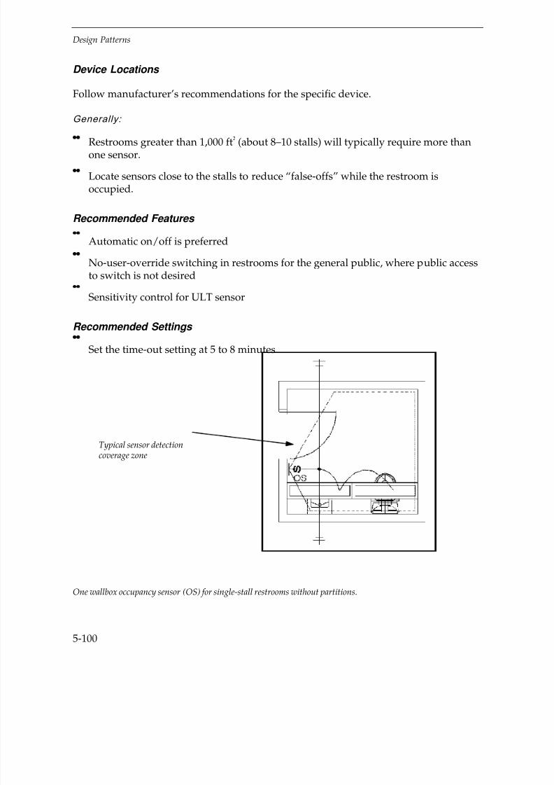
7/21/2019 Lighting Controls Patterns for Design
http://slidepdf.com/reader/full/lighting-controls-patterns-for-design 200/299
Design Patterns
5-100
Device Locations
Follow manufacturer’s recommendations for the specific device.
Generally:
Restrooms greater than 1,000 ft2 (about 8–10 stalls) will typically require more than
one sensor.
Locate sensors close to the stalls to reduce “false-offs” while the restroom isoccupied.
Recommended Features
Automatic on/off is preferred
No-user-override switching in restrooms for the general public, where public accessto switch is not desired
Sensitivity control for ULT sensor
Recommended Settings
Set the time-out setting at 5 to 8 minutes
One wallbox occupancy sensor (OS) for single-stall restrooms without partitions.
Typical sensor detectioncoverage zone
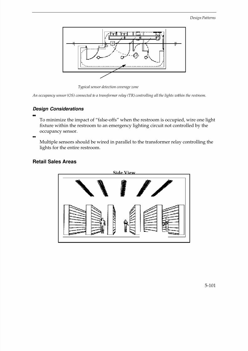
7/21/2019 Lighting Controls Patterns for Design
http://slidepdf.com/reader/full/lighting-controls-patterns-for-design 201/299
Design Patterns
5-101
An occupancy sensor (OS) connected to a transformer relay (TR) controlling all the lights within the restroom.
Design Considerations
To minimize the impact of “false-offs” when the restroom is occupied, wire one lightfixture within the restroom to an emergency lighting circuit not controlled by theoccupancy sensor.
Multiple sensors should be wired in parallel to the transformer relay controlling thelights for the entire restroom.
Retail Sales Areas
Side View
Typical sensor detection coverage zone

7/21/2019 Lighting Controls Patterns for Design
http://slidepdf.com/reader/full/lighting-controls-patterns-for-design 202/299
Design Patterns
5-102
Conventional wiring
Conventional Wiring—ExampleFixture Type: Power density: 2.0 W/ft2
8’ industrial Light level: 100 FC
6-F32T8 lamps Switching: at sub-panelsw/electronic ballastsPendant mounted
Key Problems and Issues
There are retail sales areas in many establishments including small specialty stores,supermarkets, pharmacies, and large retail department stores. Key activities involveselecting or stacking various goods in a shelving display. The lighting system for nearlyall retail operations is a very important marketing tool. Since lighting plays such an
important role in the retail environment, lighting control applications to save energy arelimited to a few successful strategies. Common occupancy and operationalcharacteristics include:
Long hours of operation when the retail area is open to customers.
Periods for restocking when the store is closed.

7/21/2019 Lighting Controls Patterns for Design
http://slidepdf.com/reader/full/lighting-controls-patterns-for-design 203/299
Design Patterns
5-103
Retail sales areas range from 300 to over 100,000 ft2 with storage aisles 6–12' wide and
20–80' long. Many new retail projects are one-story buildings that have access todaylight via skylights. Typical hours of use range from 12 to 24 hours per day,sometimes 7 days a week.
Best Control Strategies
Daylighting
Adaptation Compensation
Conventional Wiring
Common Fixture Types
The type of lighting used for display varies widely based on the desired ambiance andthe items being sold. Ambient lighting systems include industrial strip fluorescentfixtures that are pendant hung from exposed ceilings, direct 2x4 fluorescent troffers,and HID lamps recessed within an acoustical ceiling. Accent and case lighting tohighlight specific display areas are also common. Light levels maintained in most retailareas are generally 70–100 FC or higher.
Switching Systems
General lighting is usually controlled at a central, secure location outside the sales area.
Some operations may use tandem-wired fixture circuits to give a lower light level whenrestocking at night.

7/21/2019 Lighting Controls Patterns for Design
http://slidepdf.com/reader/full/lighting-controls-patterns-for-design 204/299
Design Patterns
5-104
Retail Sales Areas – Daylighting - Photosensor, Photoswitch
Application and Savings
Daylighting is a good strategy for retail sales areas with abundant daylight from
skylights or windows. Skylights should be uniformly spaced at 1.5–2 times the ceilingheight and represent 3–5% of the roof area. For sales areas illuminated with fluorescentfixtures, use photosensors with fluorescent dimming ballasts. For HID fixture systems,use photoswitch control with bi-level ballasts. Generally, one photosensor orphotoswitch controlling a large number of lighting circuits via a transformer-relay orcontroller is sufficient for uniform daylighting applications. Lighting energy savingsmay be 40–70% depending on the length of time the facility is operated. In addition,there may be peak demand savings because the lighting energy savings normallycoincides with peak building electrical use.
Control Devices
Photosensor
Use electronic dimming ballasts controlled via a local master controller(as illustrated).
Photoswitch
Use 2-step light level ballasts for HID applications.
Use tandem-wired ballasts for fluorescent applications.
Savings

7/21/2019 Lighting Controls Patterns for Design
http://slidepdf.com/reader/full/lighting-controls-patterns-for-design 205/299
Design Patterns
5-105
Caution:
Photoswitches are difficult to calibrate correctly to ensure that lights won’t cyclefrequently.
Device Locations
Follow the manufacturer’s recommendations
Generally:
Mount photosensor to “view” down into the space.
Mount photoswitch to “view” either up into the skylight or down into the space.
In either case, the sensor is calibrated to the light level at the workplane.
One photosensor (LS) connected in parallel to multiple local master controllers (LMC) to control the lighting within
storage aisles and circulation areas separately.
To Circulation AisleSub-Panels
5x5 Skylights @ 4%Floor Area
To Storage AisleSub-Panels
7/21/2019 Lighting Controls Patterns for Design
http://slidepdf.com/reader/full/lighting-controls-patterns-for-design 206/299
Design Patterns
5-106
Recommended Features
For sensor viewing down into space, sensing range from 5 to over 150 FC
For sensor viewing up into skylight, sensing range from 100 to over 1,000 FC
Adjustable On and Off deadband setting for Photoswitch devices
Adjustable time delay from 1–5 minutes
Deadband and time delay settings will prevent lights from cycling on and off when light levels are close to the setpoint or when daylight varies due to clouds.
Recommended Settings
Follow manufacturer’s recommendations
Generally:
Set time delay at 5 minutes
Carefully calibrate the photoswitch or sensor setpoint to the desired light level in thework area.
Design Considerations
Use separate daylighting control circuits and sensors for areas with:
Different light level requirements (circulation vs. storage aisles)
Different daylight distribution due to variations in skylight spacing or size.

7/21/2019 Lighting Controls Patterns for Design
http://slidepdf.com/reader/full/lighting-controls-patterns-for-design 207/299
Design Patterns
5-107
Retail Sales Areas - Adaptation Compensation –Time Clock,Powerline-Carrier System, Relay System, Building Automation System
Application and Savings
Adaptation compensation is a good strategy for retail establishments open 18–24 hoursa day where high interior light levels (80–100 FC) can be lowered when it is darkoutside to provide easier visual adaptation for customers as they enter the store atnight. Lighting circuit design requires tandem wiring for fluorescent fixtures and bi-level ballasts for HID applications. An automatic timing system is then installed tostep down the lights during night-time operation. A more cost-effective alternativesolution in sales areas with skylights is to simply install fewer fixtures, allowingdaylight to provide the added light levels during the day. Timing systems range fromsimple time clocks with relays at sub-panels to Building Automation Systems. Energysavings for non-daylight applications are normally at off peak hours and range from
20–30%. Energy savings for daylight applications range from 30–50% and generallycoincide with peak building electrical use.
Control Devices
Time Clock
Small buildings under 20,000 ft2
Powerline-Carrier System
Existing large buildings
Relay System
Large buildings
Savings
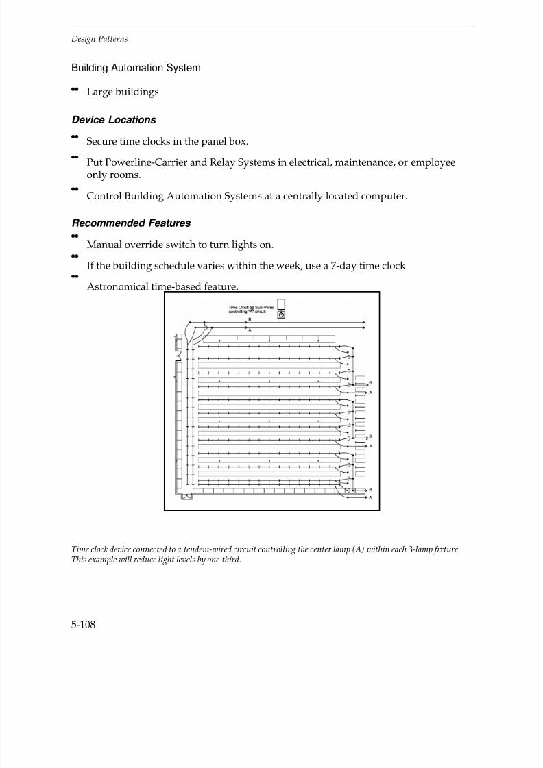
7/21/2019 Lighting Controls Patterns for Design
http://slidepdf.com/reader/full/lighting-controls-patterns-for-design 208/299
Design Patterns
5-108
Building Automation System
Large buildings
Device Locations
Secure time clocks in the panel box.
Put Powerline-Carrier and Relay Systems in electrical, maintenance, or employeeonly rooms.
Control Building Automation Systems at a centrally located computer.
Recommended Features
Manual override switch to turn lights on.
If the building schedule varies within the week, use a 7-day time clock
Astronomical time-based feature.
Time clock device connected to a tendem-wired circuit controlling the center lamp (A) within each 3-lamp fixture.This example will reduce light levels by one third.

7/21/2019 Lighting Controls Patterns for Design
http://slidepdf.com/reader/full/lighting-controls-patterns-for-design 209/299
Design Patterns
5-109
Recommended Settings
Set stepped OFF and ON times for reduced light levels to approximately correspondwith sunrise and sunset.
Design Considerations
Use tandem-wired or bi-level ballast control circuits to reduce the maximuminstalled ambient light levels by 1/2–1/3.
Don’t control emergency circuits or special display or case lighting.
Warehouses
Side view
Top view

7/21/2019 Lighting Controls Patterns for Design
http://slidepdf.com/reader/full/lighting-controls-patterns-for-design 210/299
Design Patterns
5-110
Conventional wiring
Conventional Wiring—ExampleFixture Type: Spacing 2.3 MHHID aisle lighter Power density: 0.8 W/ft2
400 watt HPS lamp Light level: 30 FCSwitching: at sub-panel
Key Problems and Issues
Warehouses have diverse usage and operational characteristics. Aisle access times andtotal hours of operation may be for short or long periods. Time of use in a given area of
a warehouse may range from 10 minutes to 2 hours. Cross aisles get more use thanstorage aisles. Warehouses also differ by the materials they store and how they storethem. Common characteristics of warehouses include:
Defined peak use periods
Lots of motion in occupied areas
Buildings range from 5000–100,000 ft2 or larger. Design light levels range from15–50 FC. Ceilings heights vary from 15–30' and stacks typically range from 7–20' high.Ambient temperature conditions may also vary greatly from refrigerated storage to hot,unconditioned spaces.
Best Control Strategies
Occupancy Responsive
Timing
Daylighting
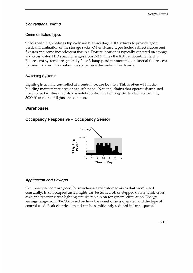
7/21/2019 Lighting Controls Patterns for Design
http://slidepdf.com/reader/full/lighting-controls-patterns-for-design 211/299
Design Patterns
5-111
Conventional Wiring
Common fixture types
Spaces with high ceilings typically use high-wattage HID fixtures to provide good
vertical illumination of the storage racks. Other fixture types include direct fluorescentfixtures and some incandescent fixtures. Fixture location is typically centered on storageand cross aisles. HID spacing ranges from 2–2.5 times the fixture mounting height.Fluorescent systems are generally 2- or 3-lamp pendant-mounted, industrial fluorescentfixtures installed in a continuous strip down the center of each aisle.
Switching Systems
Lighting is usually controlled at a central, secure location. This is often within the building maintenance area or at a sub-panel. National chains that operate distributed
warehouse facilities may also remotely control the lighting. Switch legs controlling5000 ft2 or more of lights are common.
Warehouses
Occupancy Responsive – Occupancy Sensor
Application and Savings
Occupancy sensors are good for warehouses with storage aisles that aren’t usedconstantly. In unoccupied aisles, lights can be turned off or stepped down, while crossaisle and receiving area lighting circuits remain on for general circulation. Energysavings range from 30–70% based on how the warehouse is operated and the type of control used. Peak electric demand can be significantly reduced in large spaces.
Savings
7/21/2019 Lighting Controls Patterns for Design
http://slidepdf.com/reader/full/lighting-controls-patterns-for-design 212/299
Design Patterns
5-112
Control Devices
Occupancy Sensor
Passive Infrared sensors are good for providing tight coverage limits within storageaisles at mounting heights of 15–40'.
Ultrasonic sensors generally work well for small warehouse areas that have lowerceiling heights.
Device Locations
Sensor location is based on the length and height of the storage aisle and the sensorcoverage pattern.
The design pattern shows a sensor at each end of a long storage aisle (over 100').The lens design limits the coverage pattern so that lights turn on reliably when theaisle is entered but coverage is not extended into the cross-aisle, which eliminates“false-ons” from general circulation.
If the storage aisle is less than 50–60', use one sensor at the normal-entry end of aisle.
Cautions:
Mount sensors at least 20' from HVAC diffusers and 10' from HID lamps. Make suresensor does not “view” radiant heating units.
For cold or warm (unconditioned) spaces, check with manufacturers for any changesin sensor coverage limits or sensor selection due to temperature.
Recommended Features
Automatic on/off
Recommended Settings
Set time-out setting from 5–10 minutes
When installing multiple sensors, fine tune one sensor to establish mountinglocation and angle, then repeat the settings for the other sensors.

7/21/2019 Lighting Controls Patterns for Design
http://slidepdf.com/reader/full/lighting-controls-patterns-for-design 213/299
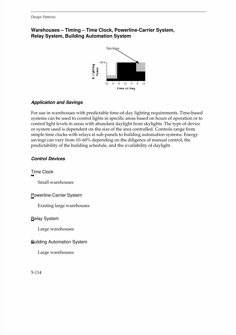
7/21/2019 Lighting Controls Patterns for Design
http://slidepdf.com/reader/full/lighting-controls-patterns-for-design 214/299
Design Patterns
5-114
Warehouses – Timing – Time Clock, Powerline-Carrier System,Relay System, Building Automation System
Application and Savings
For use in warehouses with predictable time-of-day lighting requirements. Time-basedsystems can be used to control lights in specific areas based on hours of operation or tocontrol light levels in areas with abundant daylight from skylights. The type of deviceor system used is dependent on the size of the area controlled. Controls range fromsimple time clocks with relays at sub-panels to building automation systems. Energysavings can vary from 10–60% depending on the diligence of manual control, thepredictability of the building schedule, and the availability of daylight.
Control Devices
Time Clock
Small warehouses
Powerline-Carrier System
Existing large warehouses
Relay System
Large warehouses
Building Automation System
Large warehouses
Savings

7/21/2019 Lighting Controls Patterns for Design
http://slidepdf.com/reader/full/lighting-controls-patterns-for-design 215/299
Design Patterns
5-115
Device Locations
Attach time clocks to the panel box.
Put powerline-carrier and relay systems in electrical or maintenance rooms.
Control building automation systems from a central computer.
Recommended Features
Manual override switch.
Use a 7-day time clock if building schedule varies day-by-day.
Use an astronomical time clock for daylighting applications.
If a Building Automation System is installed, consider using time-based features tocontrol lighting circuits.
Separate time clocks (TC) controlling the lights for the storage area and receiving area at each sub-panel.
TC Receiving Area
Time Panel
Clock
TC Storage Aisle
Time Panel
Clock
To Storage Aisle Panel
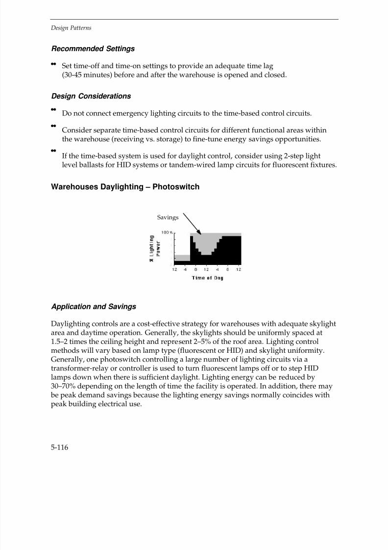
7/21/2019 Lighting Controls Patterns for Design
http://slidepdf.com/reader/full/lighting-controls-patterns-for-design 216/299
Design Patterns
5-116
Recommended Settings
Set time-off and time-on settings to provide an adequate time lag(30-45 minutes) before and after the warehouse is opened and closed.
Design Considerations
Do not connect emergency lighting circuits to the time-based control circuits.
Consider separate time-based control circuits for different functional areas withinthe warehouse (receiving vs. storage) to fine-tune energy savings opportunities.
If the time-based system is used for daylight control, consider using 2-step lightlevel ballasts for HID systems or tandem-wired lamp circuits for fluorescent fixtures.
Warehouses Daylighting – Photoswitch
Application and Savings
Daylighting controls are a cost-effective strategy for warehouses with adequate skylightarea and daytime operation. Generally, the skylights should be uniformly spaced at1.5–2 times the ceiling height and represent 2–5% of the roof area. Lighting controlmethods will vary based on lamp type (fluorescent or HID) and skylight uniformity.Generally, one photoswitch controlling a large number of lighting circuits via atransformer-relay or controller is used to turn fluorescent lamps off or to step HID
lamps down when there is sufficient daylight. Lighting energy can be reduced by30–70% depending on the length of time the facility is operated. In addition, there may be peak demand savings because the lighting energy savings normally coincides withpeak building electrical use.
Savings
7/21/2019 Lighting Controls Patterns for Design
http://slidepdf.com/reader/full/lighting-controls-patterns-for-design 217/299
Design Patterns
5-117
Control Devices
Photoswitch
Use 2-step light level ballasts for HID applications (as illustrated).
Use tandem-wired ballasts for fluorescent applications.
Cautions:
Carefully calibrate and adjust the system.
Device Locations
Follow the manufacturer’s recommendations for the specific device.
General l y t here are 2 approaches :
Mount sensor to “view” up into the skylight, or
Mount sensor to “view” down into the space.
In either case, the sensor is calibrated to the light level at the workplane.
Recommended Features
For sensor viewing down into space, sensing range from 5 to over 150 FC
For sensor viewing up into skylight, sensing range from 100 to over 1000 FC
Adjustable On and Off deadband setting
Adjustable time delay from 1–5 minutes
Deadband and time delay settings will prevent lights from cycling on and off whenlight levels are close to the setpoint or when daylight varies due to clouds.

7/21/2019 Lighting Controls Patterns for Design
http://slidepdf.com/reader/full/lighting-controls-patterns-for-design 218/299
Design Patterns
5-118
One photoswitch (PS) in a representative location is connected to a transformer-relay (TR) controlling all lights in
the storage aisles; an identical setup controls in the receiving area.
Recommended Settings
Follow manufacturer’s recommendations
Generally:
Set time delay at 5 minutes
Carefully calibrate the photoswitch setpoint with the desired light level in the workarea.
Design Considerations
Use separate daylighting control circuits and sensors for areas with:
— Different light level requirements (receiving vs. storage).
— Different daylight distribution due to variations in skylight spacing or size.

7/21/2019 Lighting Controls Patterns for Design
http://slidepdf.com/reader/full/lighting-controls-patterns-for-design 219/299

7/21/2019 Lighting Controls Patterns for Design
http://slidepdf.com/reader/full/lighting-controls-patterns-for-design 220/299
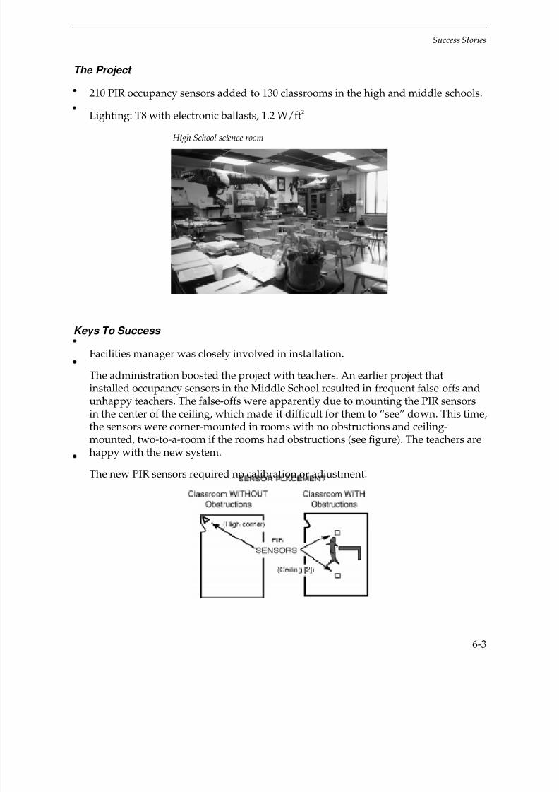
7/21/2019 Lighting Controls Patterns for Design
http://slidepdf.com/reader/full/lighting-controls-patterns-for-design 221/299
Success Stories
6-3
The Project
210 PIR occupancy sensors added to 130 classrooms in the high and middle schools.
Lighting: T8 with electronic ballasts, 1.2 W/ft2
High School science room
Keys To Success
Facilities manager was closely involved in installation.
The administration boosted the project with teachers. An earlier project thatinstalled occupancy sensors in the Middle School resulted in frequent false-offs and
unhappy teachers. The false-offs were apparently due to mounting the PIR sensorsin the center of the ceiling, which made it difficult for them to “see” down. This time,the sensors were corner-mounted in rooms with no obstructions and ceiling-mounted, two-to-a-room if the rooms had obstructions (see figure). The teachers arehappy with the new system.
The new PIR sensors required no calibration or adjustment.

7/21/2019 Lighting Controls Patterns for Design
http://slidepdf.com/reader/full/lighting-controls-patterns-for-design 222/299

7/21/2019 Lighting Controls Patterns for Design
http://slidepdf.com/reader/full/lighting-controls-patterns-for-design 223/299
Success Stories
6-5
Success Story: Laboratory: Occupancy Sensors
Stanford University
Palo Al t o, CA
“Besides the track record of the manufacturer, it’s important to get quality installation andsetup. I look for good local support.”
Scott GouldEnergy Engineer
SENSOR (Chemistry Lab)

7/21/2019 Lighting Controls Patterns for Design
http://slidepdf.com/reader/full/lighting-controls-patterns-for-design 224/299
Success Stories
6-6
Ultrasonic sensor, one of two in room
The Project
Six undergraduate chemistry teaching labs, total 6200 ft 2
Lighting: 4' 2-HO-lamp fixtures, 2.5 W/ft2
Added two ultrasonic occupancy sensors per lab
Keys To Success
Due to the 5’-high backs on the lab benches, two sensors per 1030 ft2 room were
specified. The manufacturer rates each sensor for 2100 ft2 in open spaces, but only
640 ft2 with partitions.
Had good manufacturer’s support during installation.

7/21/2019 Lighting Controls Patterns for Design
http://slidepdf.com/reader/full/lighting-controls-patterns-for-design 225/299
Success Stories
6-7
When the school first tried occupancy sensors, the maintenance staff didn’tunderstand how to adjust them, so they disconnected the sensors when they“didn’t work.” Now the staff is trained and have accepted the sensors.
Economics
Estimated lighting use savings: 41% (from 4280 hr/yr to 2555 hr/yr)Total Cost: $4490Estimated energy cost savings: $2220/yrPayback: 2.0 years
Success Story: Library Stacks: Occupancy Sensors
Bryant College
Smi t hfi el d, RI
“The library just sits there, does its own thing, and nobody worries about it.”
William Gillmore,Energy Coordinator
The Project
Bryant College is a business college with 3000 full-time and 2000 part-timeundergraduate and graduate students.
PIR occupancy sensors added to 36,200 ft2 of library stack areas.
Stacks are open 18 hr/day for students; cleaning occurs at night.
Lighting: single-tube fixtures, T8 lamps, electronic ballasts
Power density: 1.08 W/ft2

7/21/2019 Lighting Controls Patterns for Design
http://slidepdf.com/reader/full/lighting-controls-patterns-for-design 226/299
Success Stories
6-8
SENSORS (Stacks with some lights off)
Keys To Success
Considered timers, but school didn’t want students to have to activate lights.
The school tested occupancy sensors from several manufacturers before selecting avendor.
Per the college’s request, the sensors were located so as to turn on lights within a
stack aisle when someone walks by the end of it — to make the stack inviting andnon-threatening.
Main circulation aisles are kept lit because they are occupied most of the time. Thisalso provides a feeling of security and the appearance of an area being open.
Lamp life: Relamping is needed only half as often (every 4 years instead of every2 years), and there is no detectable light depreciation.

7/21/2019 Lighting Controls Patterns for Design
http://slidepdf.com/reader/full/lighting-controls-patterns-for-design 227/299
Success Stories
6-9
The sensor manufacturer’s representative assisted with the layout and duringinstallation.
Installed by staff electricians.
Time delay setting: 5 minutes
Economics
Reduced on-time (per college monitoring): 9.8 hr/day(lights had been on 24 hr/day)Total Cost: $6900Savings: $14,200/yrPayback: 0.48 years
SENSOR (at end of stack aisle)
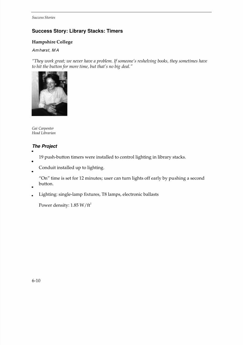
7/21/2019 Lighting Controls Patterns for Design
http://slidepdf.com/reader/full/lighting-controls-patterns-for-design 228/299
Success Stories
6-10
Success Story: Library Stacks: Timers
Hampshire College
Amherst, M A
“They work great; we never have a problem. If someone’s reshelving books, they sometimes haveto hit the button for more time, but that’s no big deal.”
Gai Carpenter Head Librarian
The Project
19 push-button timers were installed to control lighting in library stacks.
Conduit installed up to lighting.
“On” time is set for 12 minutes; user can turn lights off early by pushing a second button.
Lighting: single-lamp fixtures, T8 lamps, electronic ballasts
Power density: 1.85 W/ft2
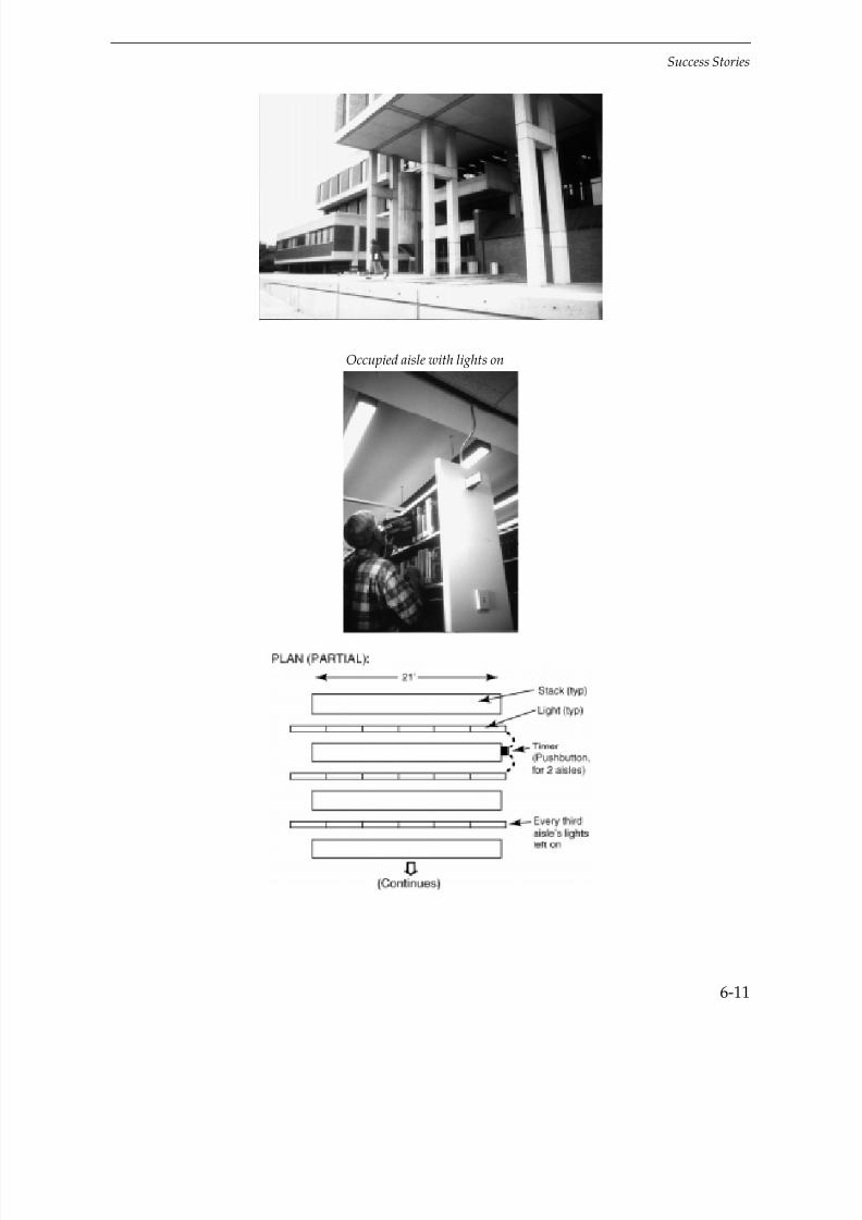
7/21/2019 Lighting Controls Patterns for Design
http://slidepdf.com/reader/full/lighting-controls-patterns-for-design 229/299
Success Stories
6-11
Occupied aisle with lights on

7/21/2019 Lighting Controls Patterns for Design
http://slidepdf.com/reader/full/lighting-controls-patterns-for-design 230/299
Success Stories
6-12
Keys To Success
Simple, inexpensive project
Per client request, only two out of every three rows are switched (by a single timer).Lights in every third row stay on to make the area look occupied and inviting.
Circulation (main) aisles are kept lit.
Hitting timer for 12 min of light
Economics
Lighting use savings: 80% — with timers lights are on less than 1000 hr/yr; withoutcontrols they were on about 5000 hr/yr
Total Cost: $1630Savings: $1298/yrPayback: 1.3 years
Success Story: Office Building: BAS
Tops Markets, Inc.
W il l i amsvi l le, NY
“The key was the close cooperation between the design engineers, the controls vendor, the utility,
and ourselves. The system works well; we use about a third less electricity than the average officebuilding, and the office lighting levels improve associate satisfaction.”
Don KellerDirector of Facilities

7/21/2019 Lighting Controls Patterns for Design
http://slidepdf.com/reader/full/lighting-controls-patterns-for-design 231/299
Success Stories
6-13
The Project
New Office building, 200,000 ft2
Building Automation System (BAS) controls about 65% of lighting, mostly by
scheduling:
At 5:30 p.m.: reduces lights to 50% output; at 10:00 p.m.: emergencylighting only
Occupants can use override switches for an additional 2 hours full light(telephone override is not yet implemented).
Lighting: Indirect, T8 with electronic ballasts, plus standard efficiency task lighting,not controlled
Lighting density: 1.1 W/ft2
, not including task lights
Lobby

7/21/2019 Lighting Controls Patterns for Design
http://slidepdf.com/reader/full/lighting-controls-patterns-for-design 232/299
Success Stories
6-14
Open Office
Cafeteria and meeting room
Keys To Success
Early coordination between BAS supplier, owner, and utility
Owner decided to invest for comfort, convenience, and productivity.
Just one main control system (the BAS) for personnel to learn
Initially, relays in lighting panels “fused” due to high ballast inrush current.Increasing the relay size from 20A to 40A solved the problem. The problem arosefrom an extremely high inrush ballast being used with a relay that only marginallymet the 20A spec.

7/21/2019 Lighting Controls Patterns for Design
http://slidepdf.com/reader/full/lighting-controls-patterns-for-design 233/299
Success Stories
6-15
Economics
For adding control of lights to BAS:Total Cost: $24,700 less
$12,000 utility
incentive = $12,700EnergySavings: $10,000/yrPayback: 1.3 years (2.5 years without incentive)
Success Story: Open Office: Occupancy Sensors
State of Connecticut
Hart ford, CT
“Working with the utility was very successful. They helped get a contractor with a good track record, and the occupants have expressed great satisfaction.”
Bruce MacLachlanEnergy ManagerState of Connecticut
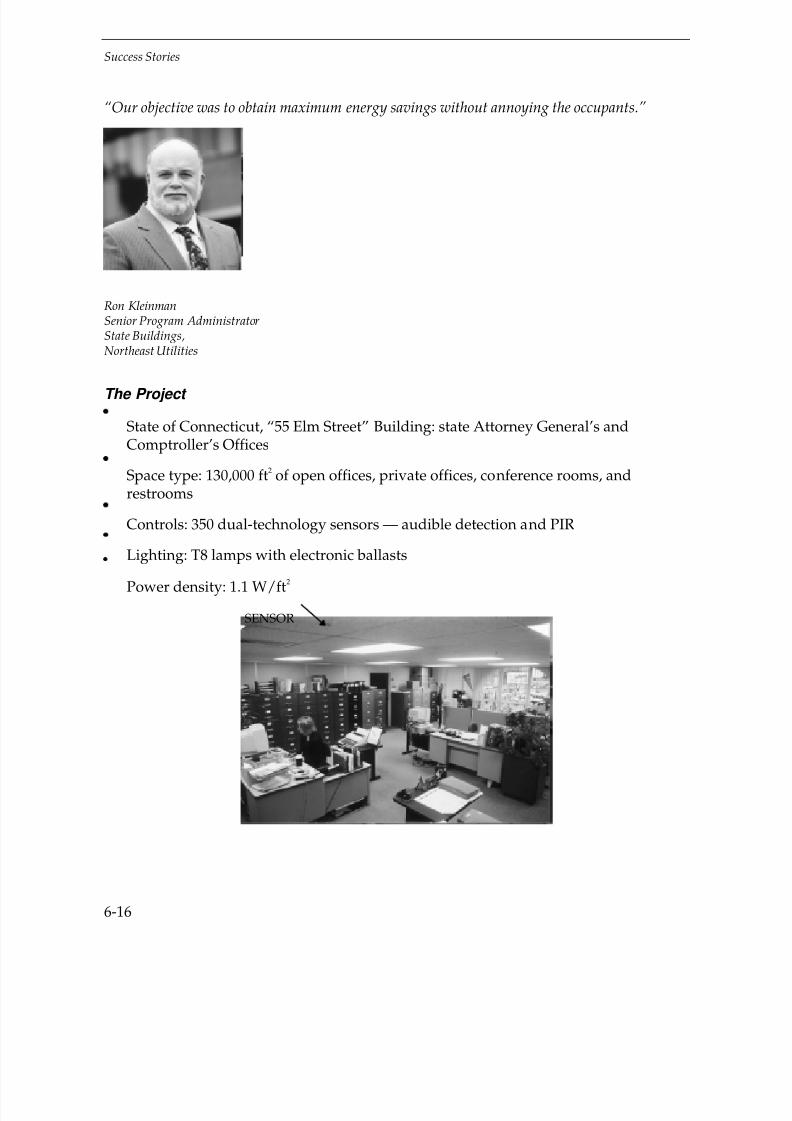
7/21/2019 Lighting Controls Patterns for Design
http://slidepdf.com/reader/full/lighting-controls-patterns-for-design 234/299
Success Stories
6-16
“Our objective was to obtain maximum energy savings without annoying the occupants.”
Ron KleinmanSenior Program AdministratorState Buildings,Northeast Utilities
The Project
State of Connecticut, “55 Elm Street” Building: state Attorney General’s andComptroller’s Offices
Space type: 130,000 ft2 of open offices, private offices, conference rooms, andrestrooms
Controls: 350 dual-technology sensors — audible detection and PIR
Lighting: T8 lamps with electronic ballasts
Power density: 1.1 W/ft2
SENSOR

7/21/2019 Lighting Controls Patterns for Design
http://slidepdf.com/reader/full/lighting-controls-patterns-for-design 235/299
Success Stories
6-17
Keys To Success
Owner and utility collaboration. Utility supplied technical design assistance, ran the job, and provided 50% co-funding.
Use of dual-technology sensors assured accurate detection. Sensors were set so that both audible and PIR signals were required to turn lights on—minimizing“false-ons”—and either detection to keep lights on—minimizing “false-offs.”
7/21/2019 Lighting Controls Patterns for Design
http://slidepdf.com/reader/full/lighting-controls-patterns-for-design 236/299
Success Stories
6-18
Economics
Estimated lighting use savings: 33%Total Cost: $51,800 less
50%
co-funding= $25,900
Estimated energy costsavings: $24,500/yrPayback: 1.1 years (2.1 years without incentive)
Success Story: Office Building: Occupancy Sensors
AlliedSignalTorr ence, CA
“We targeted smaller spaces like private offices, where a zone on the low-voltage relay systemdoesn’t make sense.”
Don PageEnergy Manager
The Project
AlliedSignal Aerospace Headquarters — office campus
Occupancy sensors were used in smaller spaces — private offices, conference rooms,lab areas, storerooms, and restrooms — within 18 buildings, sensors coverapproximately 280,000 ft
2.
A total of 1,800 ultrasonic occupancy sensors, about 80% wallbox sensors and 20%
ceiling sensors, were installed. Sensors were not used in larger spaces, e.g., open offices, which are controlled by a
relay (sweep) system.
Lighting: T12 lamps (F40 and F34), magnetic ballasts
Power density: 2.0 W/ft2

7/21/2019 Lighting Controls Patterns for Design
http://slidepdf.com/reader/full/lighting-controls-patterns-for-design 237/299
Success Stories
6-19
SENSOR (Private office with wallbox sensor)
SENSOR (Secretarial bay)
Keys To Success
Chose smaller rooms that are not suitable for zones on the sweep system.
Avoided areas where movement of guards would frequently turn lights on.
On the wallbox sensors, management encouraged setting the Manualon/Auto off option:
so lights don’t come on due to brief entry (e.g., just to drop something off)
to increase energy savings and awareness.

7/21/2019 Lighting Controls Patterns for Design
http://slidepdf.com/reader/full/lighting-controls-patterns-for-design 238/299
Success Stories
6-20
SENSOR (Conference room)
Economics
Total Cost: $120,000 less $30,000rebate = $90,000
Savings: $69,000/yrPayback: 1.3 years (1.7 years without utility incentive payment)
Success Story: Office and Manufacturing: Occupancy Sensors
Applied MaterialsSanta Clara, CA
“Layout should be by a qualified representative of the product.”
Patrick WongEnergy ManagementProject Manager

7/21/2019 Lighting Controls Patterns for Design
http://slidepdf.com/reader/full/lighting-controls-patterns-for-design 239/299
Success Stories
6-21
The Project
Installed approximately 2500 occupancy sensors, mostly ultrasonic, in 32 buildings(about 1,000,000 ft2)
Space types included open offices, private offices, conference rooms, lobbies,
corridors, restrooms, laboratories, manufacturing areas, and warehouse.
Sensors turn off lighting and also set back variable air volume (VAV) boxes tounoccupied-mode operation.
SENSOR (Open office)
Keys To Success
Occupancy sensor manufacturer assisted with the design process.
Used a lot of ultrasonic sensors in open offices to assure “seeing” around partitions.
Used dual-technology sensors in manufacturing areas and clean rooms to avoidfalse-offs.
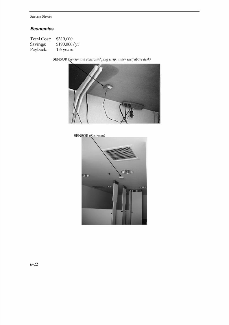
7/21/2019 Lighting Controls Patterns for Design
http://slidepdf.com/reader/full/lighting-controls-patterns-for-design 240/299
Success Stories
6-22
Economics
Total Cost: $310,000Savings: $190,000/yrPayback: 1.6 years
SENSOR (Sensor and controlled plug strip, under shelf above desk)
SENSOR (Restroom)

7/21/2019 Lighting Controls Patterns for Design
http://slidepdf.com/reader/full/lighting-controls-patterns-for-design 241/299
Success Stories
6-23
Success Story: Retail: Occupancy Sensors
Blom Brothers Furniture
Vineland, NJ
“The sensors save us money and the customers aren’t bothered. We haven’t had any problemswith the system.”
Scott BlomVice-President
The Project
Furniture showroom, 21,500 ft2
Forty ultrasonic occupancy sensors control lights in individual furniture “scenes” beyond front of store. Approximately one-half of the general lighting is controlled by occupancy sensors.
Ceiling is approximately 10’, and there are numerous 7’ partitions.
Lighting (general): 45W par 38 halogen floods.
Lighting density: 1.8 W/ft2 (not including display table lamps).

7/21/2019 Lighting Controls Patterns for Design
http://slidepdf.com/reader/full/lighting-controls-patterns-for-design 242/299
Success Stories
6-24
SENSOR (A “scene” with occupancy sensor and the par lamps it controls)
SENSOR (A “scene” with its own sensor)
7/21/2019 Lighting Controls Patterns for Design
http://slidepdf.com/reader/full/lighting-controls-patterns-for-design 243/299
Success Stories
6-25
Keys To Success
To attract customers, all lights are kept on within 20–30’ of the front window and inthe main aisle. Also, some lights are kept on in the “scenes.” The owner reports nonegative impact on customers from controlling the lights.
Used ultrasonic, not PIR, sensors because of partitions.
Owner worked directly with controls vendor to arrive at design.
Vendor did a trial installation in one area to assure owner satisfaction.
Electrician was willing to stay on the job until he was sure everything workedproperly.
Economics
Owner reports that sensors turn off controlled lights for 7 hours (out of 12) per day onaverage.Total Cost: $6300Estimatedenergy costsavings: $3200/yrPayback: 2.0 years
Success Story: Retail: Photosensors
Wal-Mart Store
Lawrence, KS
“Because the results were so good in this store, we’ve built two more ‘Eco’ stores, in Moore,Oklahoma and City of Industry, California.”
Patty PerezGreen Coordinator

7/21/2019 Lighting Controls Patterns for Design
http://slidepdf.com/reader/full/lighting-controls-patterns-for-design 244/299
Success Stories
6-26
Keys To Success
The skylit area is attractive to customers and employees. The Wall Street Journalreported that cash register records indicate that sales also benefit:
According to Tom Seay, who was then the company’s vice president for real estate, sales were“significantly higher” in the daylit half of the store, and also higher there than in the samedepartments at other stores. Employees in the half without daylighting continue to try tohave their departments moved to the daylit side. —Wall Street Journal
A fresnel-lens light-gathering skylight

7/21/2019 Lighting Controls Patterns for Design
http://slidepdf.com/reader/full/lighting-controls-patterns-for-design 245/299
Success Stories
6-27
Store interior showing skylights and (dimmed) pendant fixtures
The Project
122,000 ft2 retail store (opened in June, 1993)
One half of the store has skylights that constitute 3.4% of the roof (in that half of the building).
Nine of the 64 total skylights are custom light-gathering “eyebrow” shape(preferred by occupants).
Lighting: 1100 no-lens T-8 direct/indirect fixtures, 1.0 W/ft2. 500 fixtures
(in the daylit half of the store) have dimming electronic ballasts controlled byphotosensors.
Photosensors installed in two of the skylight wells control all daylight dimming.
Micro-processor control selects the lighting mode:
— Daytime: daylighting (photosensor control) adjusts lights for available daylight
— Nighttime: timing (programmable time clock) dims lights to 50% 15 minutes before closing and to 25% at closing
— Management can override light level, e.g., for special cleaning.

7/21/2019 Lighting Controls Patterns for Design
http://slidepdf.com/reader/full/lighting-controls-patterns-for-design 246/299
Success Stories
6-28
Economics
Power monitoring showed 47% lighting savings during the daytime in the daylit half of the store and over 50% average nighttime lighting reduction.
Total Cost: $59,000Energy savings: $21,000/yrPayback: 2.8 years
Sales benefit (see keys to success): This was not quantified, but just a 1% increase insales in the daylit half of the store, based on the industry average (not Wal-Mart)retail sales of $300/ft
2/yr, would give $180,000/yr in increased sales.
Success Story: Warehouse: Occupancy Sensors
A.A.I. Warehouse
Smithfield, RI
“We do everything we can to increase the company’s efficiency. This is part of that, and it’s beensuper-successful.”
Robert V. LalloChief Operating Officer

7/21/2019 Lighting Controls Patterns for Design
http://slidepdf.com/reader/full/lighting-controls-patterns-for-design 247/299
Success Stories
6-29
The Project
A.A.I. Warehouse, Smithfield, RI — active storage for gift and jewelry storagefacility
Forty-six PIR occupancy sensors added to 30,000 ft2
Lighting: T8 lamps, electronic ballasts
Power density: 1.7 W/ft2
SENSORS (Pointing into aisles)

7/21/2019 Lighting Controls Patterns for Design
http://slidepdf.com/reader/full/lighting-controls-patterns-for-design 248/299
Success Stories
6-30
SENSORS (At center aisle)
Typical aisle
Keys To Success
Used PIR sensors because of high mounting (25 ft)
Occupancy sensor manufacturer assisted with commissioning
Mounted the first sensors on flex-cable to set position. Mounted remaining sensorsto match the established location and angle using index markings on the sensor,which avoided having to fine-tune each sensor individually.

7/21/2019 Lighting Controls Patterns for Design
http://slidepdf.com/reader/full/lighting-controls-patterns-for-design 249/299
Success Stories
6-31
Sensor doesn’t turn lights on until 8 ft into a storage aisle to avoid false tripping.
Time delay setting: 10 minutes
Center aisle is kept lit for emergency egress and to provide some light at themidway point between the long stacks.
Economics
Total Cost: $12,500Savings: $11,900/yrPayback: 1.1 years

7/21/2019 Lighting Controls Patterns for Design
http://slidepdf.com/reader/full/lighting-controls-patterns-for-design 250/299
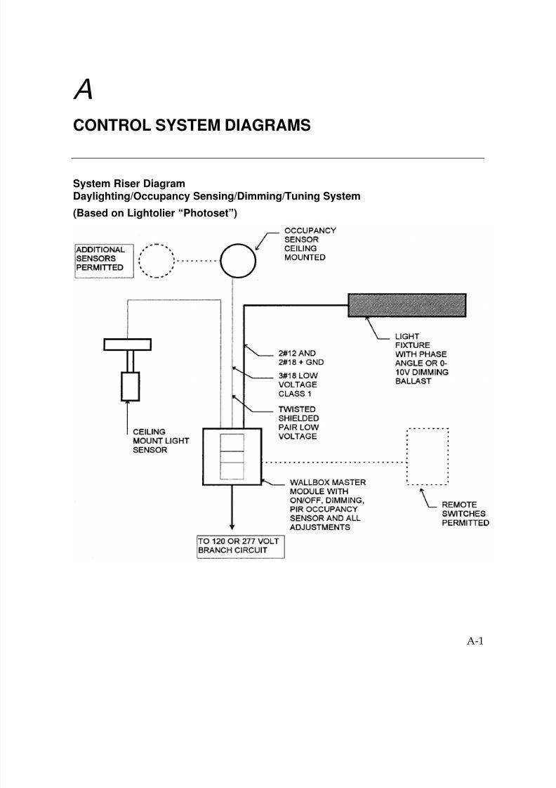
7/21/2019 Lighting Controls Patterns for Design
http://slidepdf.com/reader/full/lighting-controls-patterns-for-design 251/299
A-1
ACONTROL SYSTEM DIAGRAMS
System Riser DiagramDaylighting/Occupancy Sensing/Dimming/Tuning System
(Based on Lightolier “Photoset”)
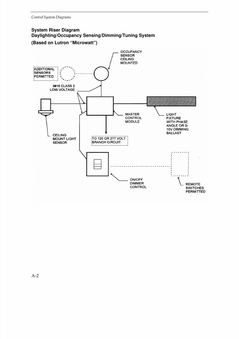
7/21/2019 Lighting Controls Patterns for Design
http://slidepdf.com/reader/full/lighting-controls-patterns-for-design 252/299
Control System Diagrams
A-2
System Riser DiagramDaylighting/Occupancy Sensing/Dimming/Tuning System
(Based on Lutron “Microwatt”)
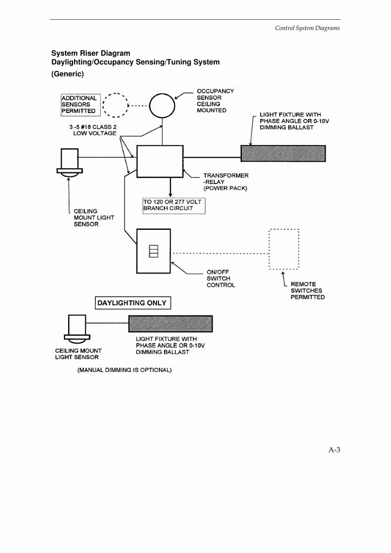
7/21/2019 Lighting Controls Patterns for Design
http://slidepdf.com/reader/full/lighting-controls-patterns-for-design 253/299
Control System Diagrams
A-3
System Riser DiagramDaylighting/Occupancy Sensing/Tuning System
(Generic)

7/21/2019 Lighting Controls Patterns for Design
http://slidepdf.com/reader/full/lighting-controls-patterns-for-design 254/299
Control System Diagrams
A-4
System Riser DiagramDaylighting/Occupancy Sensing/Tuning System
(Generic)

7/21/2019 Lighting Controls Patterns for Design
http://slidepdf.com/reader/full/lighting-controls-patterns-for-design 255/299
B-1
BCODES
The newer building codes require some kind of automatic shut off of lighting. This may be a timer, time clock, occupancy sensor, photosensor, or other device that turns off lighting without human intervention.
The code governing your project likely will be based on one of the following standardsor on the California law.
Remember, codes are minimum requirements. Often the designer can choose controlsthat are better.
ASHRAE/IES Standard 90.1-1989
While there is no single US Energy Code, the Energy Policy Act of 1992 designatedASHRAE/IES 90.1-1989 as the MINIMUM standard that all state and local energy codesmust meet. For Federal buildings, there is a federal energy code, which is essentially90.1-1989 with minor revisions. Most state energy codes are either simplifications of 90.1-1989 or use 90.1-1989 by reference.
To comply with 90.1-1989, and most state and federal codes, controls systems must bedesigned to meet the following requirements.
Interior Lighting
Number of “control points” (e.g., switches) required:
1 per SPACE
+
1 per TASK
OR
1 per 450 FT2
whichever isless stringent

7/21/2019 Lighting Controls Patterns for Design
http://slidepdf.com/reader/full/lighting-controls-patterns-for-design 256/299
Codes
B-2
600-square-foot office with three workstations
• 1 for the space plus 3 per the tasks = 4
• 1 for the space plus 2 per the area = 3 (use)
Thus: Need 3 control points (e.g., 3 switches).
Notes:
• Advanced controls like occupancy sensors count for more than one “control point”(see table on next page)
• Manual controls must be readily accessible to occupants of the space
• Multiple switches for the same light count as one control point
• There are exceptions for security lighting and for lighting in large spaces switched aswhole (e.g., auditoriums)
• See Standard 90.1 for details
Example

7/21/2019 Lighting Controls Patterns for Design
http://slidepdf.com/reader/full/lighting-controls-patterns-for-design 257/299
Codes
B-3
EQUIVALENT CONTROL POINTS FOR ADVANCED CONTROLS:
Type of ControlEquivalent Number of
Control Points
Manually operated on-off switch 1
Occupancy sensor 2
Timer—Programmed from the space being controlled 2
Three-level (including off) step control or pre-set dimming 2
Four-level (including off) step control or pre-set dimming 3
Automatic or continuous dimming 3
Example
If you use an occupancy sensor for the office in the example on previous page, then:
• The occupancy sensor counts as 2 control points, so you just need 1 switch inaddition to make the required 3 control points. The occupancy sensor eliminates therequirement for 2 of the manual switches.
Exterior Lighting
Exterior lighting must be automatically switched by photocell or by 7-day timer.
ASHRAE/IES Standard 90.1P
This standard (proposed as of this writing) revises the Standard 90.1 controlrequirements.
While the exact requirements are still being developed, it is certain that automatic-shut-off controls will be required for most lighting systems. These requirements will favoroccupancy sensors but will also permit time clock and photoelectric controls.
California Title 24
Since 1993, California’s Building Energy Efficiency Standards, part of the State BuildingCode (Title 24), have required automatic-shut-off controls and other provisions forlighting systems. In fact, Title 24’s requirements were used as the basis of ASHRAE/IES90.1P controls requirements. In general, projects or spaces over 5,000 ft2 must employautomatic-shut-off controls for lighting systems. California’s code will probably changeto match 90.1P when it is approved.

7/21/2019 Lighting Controls Patterns for Design
http://slidepdf.com/reader/full/lighting-controls-patterns-for-design 258/299
B-4

7/21/2019 Lighting Controls Patterns for Design
http://slidepdf.com/reader/full/lighting-controls-patterns-for-design 259/299
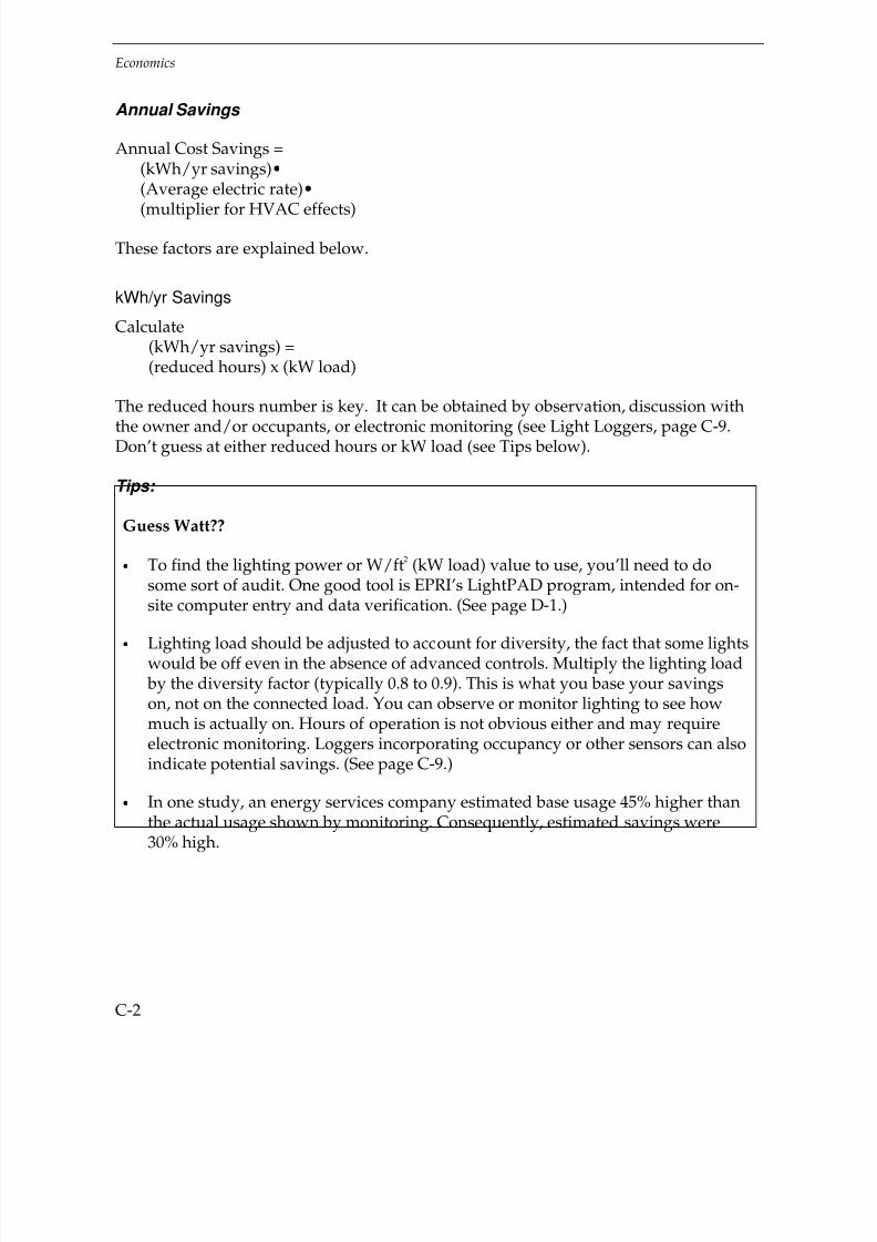
7/21/2019 Lighting Controls Patterns for Design
http://slidepdf.com/reader/full/lighting-controls-patterns-for-design 260/299
Economics
C-2
Annual Savings
Annual Cost Savings =(kWh/yr savings)•(Average electric rate)•
(multiplier for HVAC effects)
These factors are explained below.
kWh/yr Savings
Calculate(kWh/yr savings) =(reduced hours) x (kW load)
The reduced hours number is key. It can be obtained by observation, discussion with
the owner and/or occupants, or electronic monitoring (see Light Loggers, page C-9.Don’t guess at either reduced hours or kW load (see Tips below).
Tips:
Guess Watt??
• To find the lighting power or W/ft2 (kW load) value to use, you’ll need to do
some sort of audit. One good tool is EPRI’s LightPAD program, intended for on-site computer entry and data verification. (See page D-1.)
• Lighting load should be adjusted to account for diversity, the fact that some lightswould be off even in the absence of advanced controls. Multiply the lighting load by the diversity factor (typically 0.8 to 0.9). This is what you base your savingson, not on the connected load. You can observe or monitor lighting to see howmuch is actually on. Hours of operation is not obvious either and may requireelectronic monitoring. Loggers incorporating occupancy or other sensors can alsoindicate potential savings. (See page C-9.)
• In one study, an energy services company estimated base usage 45% higher thanthe actual usage shown by monitoring. Consequently, estimated savings were
30% high.
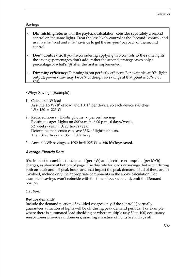
7/21/2019 Lighting Controls Patterns for Design
http://slidepdf.com/reader/full/lighting-controls-patterns-for-design 261/299
Economics
C-3
Savings
• Diminishing returns: For the payback calculation, consider separately a secondcontrol on the same lights. Treat the less likely control as the “second” control, anduse its added cost and added savings to get the marginal payback of the second
control.
• Don’t double dip: If you’re considering applying two controls to the same lights,the savings percentages don’t add; rather the second strategy saves only apercentage of what’s left after the first is implemented.
• Dimming efficiency: Dimming is not perfectly efficient. For example, at 20% lightoutput, power draw may be 32% of design, so savings at that point is 68%, not80%.
kWh/yr Savings (Example):
1. Calculate kW loadAssume 1.5 W/ft
2 of load and 150 ft
2 per device, so each device switches
1.5 x 150 = 225 W
2. Reduced hours = Existing hours x per cent savingsExisting usage: Lights on 8:00 a.m. to 6:00 p.m., 6 days/week,52 weeks/year = 3120 hours/yearDetermine that sensor can save 35% of lighting hours.Then 3120 hr/yr x .35 = 1092 hr/yr
3. Annual kWh savings = 1092 hr @ 225 W = 246 kWh/yr saved.
Average Electric Rate
It’s simplest to combine the demand (per kW) and electric consumption (per kWh)charges, as shown at bottom of page. Use this rate for loads or savings that occur during both on-peak and off-peak hours and that impact the peak demand. If all of these aren’tinvolved, include only the appropriate components in the above calculation. Forexample if savings won’t coincide with the time of peak demand, omit the Demandportion.
Caution:
Reduce demand?Include the demand portion of avoided charges only if the control(s) virtuallyguarantees a fraction of lights will be off during peak demand periods. For example:where there is automated load shedding or where multiple (say 50 to 100) occupancysensor zones provide randomness, assuring a fraction of lights are always off.

7/21/2019 Lighting Controls Patterns for Design
http://slidepdf.com/reader/full/lighting-controls-patterns-for-design 262/299

7/21/2019 Lighting Controls Patterns for Design
http://slidepdf.com/reader/full/lighting-controls-patterns-for-design 263/299
Economics
C-5
Annual Cost Savings
Combine these factors as follows.
Annual Cost Savings (Example):
$/yr saved =246 kWh/year x $0.077/kWh x 1.15= $21.78 saved per year
where 1.15 = multiplier for HVAC effects (New York City) — see above
Payback
The Simple Payback Period is the incremental cost divided by the annual savings.
Payback (Example):
The simple payback period is:First Cost/Annual Savings =$59.45 / $21.78 per year = 2.7 years
Generally, paybacks of less than 3 years indicate an excellent investment. Paybacks between 3 and 7 years are acceptable depending on the owner. Paybacks longer than7 years are generally too long.
“We burn daylight.”
-W. S.
Daylighting
To find lighting fixtures for which you should consider photosensor controls(to utilize daylight):
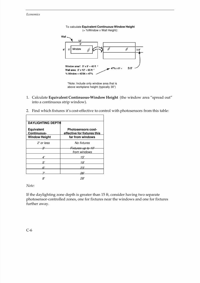
7/21/2019 Lighting Controls Patterns for Design
http://slidepdf.com/reader/full/lighting-controls-patterns-for-design 264/299
Economics
C-6
To calculate Equivalent Continuous-Window Height(= %Window x Wall Height):
*Note: Include only window area that isabove workplane height (typically 30”)
1. Calculate Equivalent Continuous-Window Height (the window area “spread out”into a continuous strip window).
2. Find which fixtures it’s cost-effective to control with photosensors from this table:
DAYLIGHTING DEPTH
EquivalentContinuous-Window Height
Photosensors cost-effective for fixtures this
far from windows
2' or less No fixtures 3' Fixtures up to 10'
from windows
4' 15'
5' 19'
6' 23'
7' 26'
8' 28'
Note:
If the daylighting zone depth is greater than 15 ft, consider having two separatephotosensor-controlled zones, one for fixtures near the windows and one for fixturesfurther away.

7/21/2019 Lighting Controls Patterns for Design
http://slidepdf.com/reader/full/lighting-controls-patterns-for-design 265/299

7/21/2019 Lighting Controls Patterns for Design
http://slidepdf.com/reader/full/lighting-controls-patterns-for-design 266/299
Economics
C-8
Four-channel logger and current transmitter (CT) on lighting circuit
Light Logger data
MON 11/04/96 07:31:01 1 Turned ON
11/04/96 09:42:23 0 Turned OFF 2:11:22
11/04/96 10:02:08 1 Turned ON
11/04/96 12:23:42 0 Turned OFF 2:21:34
11/04/96 13:24:51 1 Turned ON
11/04/96 16:58:34 0 Turned OFF 3:33:43
11/04/96 18:43:06 1 Turned ON11/04/96 18:54:25 0 Turned OFF 0:11:19
TUE 11/05/96 08:15:01 1 Turned ON
11/05/96 19:10:35 0 Turned OFF 10:55:34
WED 11/06/96 10:46:37 1 Turned ON
11/06/96 17:17:05 0 Turned OFF 6:30:28
11/06/96 18:30:10 1 Turned ON
11/06/96 18:42:14 0 Turned OFF 0:12:04
THU 11/07/96 08:05:12 1 Turned ON
11/07/96 12:30:48 0 Turned OFF 4:25:36
11/07/96 13:29:55 1 Turned ON
11/07/96 19:26:11 0 Turned OFF 5:56:16
FRI 11/08/96 07:08:47 1 Turned ON
11/08/96 15:06:31 0 Turned OFF 7:57:44
11/08/96 18:26:22 1 Turned ON
11/08/96 18:32:53 0 Turned OFF 0:06:31

7/21/2019 Lighting Controls Patterns for Design
http://slidepdf.com/reader/full/lighting-controls-patterns-for-design 267/299
Economics
C-9
Plot of light logger data
Private Office 30611/4/96 – 11/25/96
Light Loggers
In an existing building, automated light loggers can be used to record when lights areon and when they might have been turned off or dimmed. Loggers may sense lightdirectly in a fixture, or monitor current in a switch leg or lighting circuit. Whenconnected to the appropriate attachments (e.g., occupancy sensors or photosensors),light loggers can estimate potential savings for virtually any control strategy.
The loggers are typically left in place for 1–2 weeks. The collected data is thendownloaded into one’s own personal computer and the results analyzed using softwareprovided with the loggers. Lighting usage can be reported in several ways, including:
• Plotted versus time for all days or for the average weekday or weekend day
• Calculated (hours and per cent of time) for a particular condition, e.g., whenunoccupied but lights on.
Loggers and/or attachments are available to record many load types, including lightingstatus (on/off), occupancy, illumination, current, power, motor run-time, rpm, etc.
Loggers can be purchased (anywhere from $200–$2000 each), leased monthly, or often borrowed free from controls vendors anxious to demonstrate potential savings.

7/21/2019 Lighting Controls Patterns for Design
http://slidepdf.com/reader/full/lighting-controls-patterns-for-design 268/299
Economics
C-10
Lamp Life Effects
The effect of various switching frequencies on lamp life and economics is shown in thetable below. As the number of times switched per day increases, assumed savingsincrease and the frequency and cost of relamping also go up. These values assume
proper equipment selection, e.g., usually rapid start lamps and ballasts with occupancysensors. See also page 3-10 for plot of data and further discussion.
Assumpt i ons here are:
• Fixture: 2-lamp, T8, 62 W / fixture
• Base case operation: 10 hr/day, 250 day/yr
• Savings from control: 35% or more, increasing with increased switching(0% in Base case)
• Electric rate (including demand): $0.08/kWh
• Relamp cost (labor + materials): $8.00 per fixture
• Net HVAC savings multiplier: 1.15 (as for New York City; see page C-5).
• Ignores ballast life effect (the effect would not be large)
• Ignores the time value of money, but energy savings show up before addedrelamping costs.
TIMES SWITCHED ON PER DAY
Timesswitched
on perday
AssumedSavings
Hours onper start
Hourslamp life
Yearscalendar
life
Addedrelamp
cost/year(Base=$0.71)
Energysaving
s peryear
NETsavingsper year
Base: 1 0% 10.00 28,300 11.3 $ — $ — $ —
5 35% 1.30 13,800 8.5 $ 0.24 $ 4.99 $ 4.76
10 42% 0.58 9,300 6.4 $ 0.54 $ 5.99 $ 5.45
15 47% 0.35 7,200 5.4 $ 0.77 $ 6.70 $ 5.94
20 50% 0.25 6,000 4.8 $ 0.96 $ 7.13 $ 6.17 30 54% 0.15 4,600 4.0 $ 1.29 $ 7.70 $ 6.41
In this example, net savings increase up to at least 30 switchings per day (lights on forabout 9 minutes each time). For lights controlled by an occupancy sensor, this wouldindicate a very short time delay setting (about 5 minutes). Similarly, switching lights off manually makes sense any time the lights will be off for 5 minutes or more.

7/21/2019 Lighting Controls Patterns for Design
http://slidepdf.com/reader/full/lighting-controls-patterns-for-design 269/299
Economics
C-11
The table on the next page compares results for three cases:
• Typical savings fractions and typical hours-lights-on, as above
• Larger savings fractions, as might occur in a warehouse or restroom
• Longer hours-lights-on (8760 hr/yr)
The table shows that, compared to Case 1 (Typical savings and hours-lights-on),in both Case 2 (Larger savings fractions) and Case 3 (Longer hours-lights-on) there is anincrease in:
• Net savings
• The ratio of energy savings to added relamp cost
Thus, under most conditions energy savings easily outweigh added relamp costs,even with frequent switching and short periods of lights-on. However, to reduce thechance of false-offs you should specify a delay setting on occupancy sensors of at leastten minutes in most applications (which will typically result in about 20 on-off cyclesper day).
For more information on lamp life, see EPRI, “It Pays to Turn Out the Lights,” listed onpage D-1.

7/21/2019 Lighting Controls Patterns for Design
http://slidepdf.com/reader/full/lighting-controls-patterns-for-design 270/299
Economics
C-12
SWITCHING EFFECTS: ADDITIONAL CASES
Timesswitched
on perday
AssumedSavings
Hourson perstart
Hourslamplife
Yearscalendar
life
Addedrelamp
cost/year(aboveBase)
Energysavingsper year
NETsavingsper year
RationEnergy
savings/Addedrelamp
1. Typical savings and hours-lights-on, from previous table:
Base:1 10% 10.00 28,300 11.3 Base=$0.71 $ — $ — n.a.
10 42% 0.58 9300 6.4 $0.54 $5.99 $5.45 11.1
20 50% 0.25 6000 4.8 $0.96 $7.13 $6.17 7.4
2. Larger savings fractions:
Base: 1 0% 10.00 28,300 11.3 Base=$0.71 $ — $ — n.a.
10 71% 0.29 6500 9.0 $0.19 $10.12 $ 9.94 54.6
20 80% 0.10 3600 7.2 $0.40 $11.41 $11.00 28.2
3. Longer hours-lights-on (8760 hr/yr):
Base: 1 0% 24.00 32,500 3.7 Base=$2.16 $ — $ — n.a.
10 42% 1.39 14,300 2.8 $0.69 $20.99 $20.30 30.6
20 50% 0.60 9500 2.2 $1.53 $24.98 $23.45 16.3

7/21/2019 Lighting Controls Patterns for Design
http://slidepdf.com/reader/full/lighting-controls-patterns-for-design 271/299
D-1
DREFERENCES AND RESOURCES
Selected References
For information on Sources, see “Organizations” on next page.
Electric Power Research Institute (EPRI), Advanced Lighting Guidelines: 1993 (Revision 1),189 pages, free to EPRI-member utilities. An excellent compendium of all importantaspects of lighting energy efficiency. Includes information on lighting sources, lightingcalculation methods, lighting systems, daylighting, occupancy sensors, time scheduling,and retrofit technologies. Especially useful are tables of luminaire system performancefor many lamps and lamp-ballast combinations in specific luminaire types.Source: EPRI.
EPRI, Commercial Lighting Efficiency Resource Book, 1991, 121 pages, free to EPRI-memberutilities. Mainly a list of resources including lighting demonstration centers, utilityincentive programs (somewhat dated at this writing), education opportunities,publications, and organizations. The Resource Book also provides backgroundinformation, examples, and specific references. Source: EPRI.
EPRI, “It Pays to Turn Off the Lights.” EPRI Lighting Bulletin, No. 4, April, 1993.Describes switching effect on lamp life with data and examples. Source: EPRI
EPRI, Lighting Evaluation System (LES) and Lighting Diagnostic and Commissioning System(LDCS) computer programs, free to EPRI-member utilities. LES and LDCS are computerprograms used with a specific brand of light logger to survey lighting usage andevaluate potential savings (LES) or evaluate the performance of an installation (LDCS).Source: EPRI.
EPRI, Lighting Fundamentals Handbook , TR-101710, 1992, 149 pages, free to EPRI-member
utilities. This useful book covers all aspects of electric lighting, including optics,photometry, lamps, ballasts, luminaires, controls, lighting needs, calculations, andeconomics. The Lighting Controls chapter has good descriptions of control strategiesand technologies, but stops short of treating specific space types. Source: EPRI.
EPRI, LightPAD 2.0 computer program, 1995, free to EPRI-member utilities. ThisWindows program allows on-site lighting audits using a laptop or pen-based computer.

7/21/2019 Lighting Controls Patterns for Design
http://slidepdf.com/reader/full/lighting-controls-patterns-for-design 272/299
References and Resources
D-2
Lighting fixtures, controls, and other variables are input in order to define and comparealternative lighting systems in terms of energy use and lighting levels. Lightingcalculations are based on the “lumen” method; the program does not do point-by-pointcalculations or isolux mapping. Source: EPRI.
EPRI, Occupancy Sensors, 1992, 6 pages, free to EPRI-member utilities. This brochuresummarizes the different technologies, gives suggested savings for various space types,and offers some excellent case studies. Source: EPRI.
Environmental Protection Agency (EPA), Light Brief, 430-F-92-005, August, 1992, free.This EPA Green Lights brochure headlined “In the Dark About Occupancy Sensors?”is very brief, but includes air pollution emissions effects of electricity conservation andsuggests what questions to ask when considering a retrofit. Source: EPA Green LightsProgram.
Lighting Research Center (LRC), Specifier Reports, Occupancy Sensors, 1993, 20 pages,
$30. Describes sensor types, adjustments, and coverage. The main purpose, though, isto present the results of extensive tests to compare to performance of various types of sensors from various manufacturers in a test room at LRC. The testing is believedflawed, however, and at this writing, a revision is in process. Source: LRC.
LRC, Specifier Reports, Dimming Electronic Ballasts, 1995, 20 pages, $30. Describes theoperation and application of dimming electronic ballasts. Test results of electricalcharacteristics (e.g., power factor, total harmonic distortion (THD), and inrush current)of specific manufacturers’ ballasts are reported. Source: LRC.
National Electrical Manufacturers Association (NEMA), NEMA Guide to LightingControls, 1992, 44 pages, $15 plus $5 S&H. Good treatment of general strategies and benefits of controls, including occupancy sensors, dimmers, and centralized controls.Source: NEMA.
Robert A. Rundquist, Karl F. Johnson, and Donald J. Aumann, “Calculating Lightingand HVAC Interactions,” ASHRAE Journal, Vol. 35, No.11, November, 1993. Provides ahand calculation form for the dollar impacts on lighting, cooling, and heating of alighting change. Components include demand and consumption electric charges,heating cost, and cooling equipment first cost impact. Cooling and heating factors foruse in the calculation are listed for 153 U.S. cities.
Allan J. Wenzel and Jerome V. Biedny, Jr., “Making Sense of Occupancy Sensors,”Consulting-Specifying Engineer, September, 1994. This article gives practicalinformation on sensor selection and savings.

7/21/2019 Lighting Controls Patterns for Design
http://slidepdf.com/reader/full/lighting-controls-patterns-for-design 273/299
References and Resources
D-3
Organizations
E Source: A membership organization that provides applications-oriented researchdesigned to advise agencies, utilities, and end-users about evolving technologies andtheir proper application. Considerable attention is paid to electric lighting. Publications
include technology review manuals, bulletins, and newsletters; annual membershipconferences provide immersion-level education and updating. E Source materials aregenerally only available to members. Address: E Source, 1033 Walnut Creek, Boulder,CO 80302. Phone: 303-440-8500. Fax: 303-440-8502. World Wide Web Home Page:http://www.esource.com.
Electric Power Research Institute (EPRI): Funded by some 700 member utilities, EPRIstudies the generation, delivery, and use of electricity, with special attention paid tocost-effectiveness and environmental concerns. At EPRI’s headquarters in Palo Alto,California, more than 350 scientists and engineers manage some 1600 ongoing projectsthroughout the world. To access EPRI lighting information, contact your local utility,generally through the commercial lighting department. EPRI member utilities cancontact the EPRI Lighting Information Office, (800)525-8555. Home page for the public:http://www.epri.com. Home page for member utilities with password:http://www.epriweb.com.
Empire State Electric Energy Research Corporation (ESEERCO): Funds, contracts for, andadministers R&D programs to improve the generation, delivery, and efficient end use of electric power. These functions are performed on behalf of its core members—sevenNew York State electric utilities—and other utilities, manufacturers, and relatedorganizations that cosponsor ESEERCO’s projects. Address: ESEERCO, 1515 Broadway,
43rd Floor, New York, NY 10036. Phone: 212-302-1212, ext 170. Fax: 212-302-1377. HomePage: http://www.eseerco.org.
Illuminating Engineering Society of North America (IESNA): The IESNA is the continent’smain lighting society. Most people and organizations in the lighting field are IESNAmembers. IESNA organizations exist in other countries and exchange nomenclature andscience. Publications include the IESNA Lighting Handbook , the quarterly Journal of theIESNA, the monthly popular magazine Lighting Design + Application, numerous IESNARecommended Practices and Standards, and other printed materials and videos. IESNAalso offers lighting classes. All IESNA publications and classes are available to membersand the public. Information on controls is embedded throughout IESNA products.Address: IESNA, 120 Wall Street, New York, NY 10020. Phone: 212-248-5000. Fax: 212-248-5017. Home page: http://www.iesna.org.
Lawrence Berkeley National Laboratory (LBNL), Department of Energy: LBNL’s Center forBuilding Science (CBS) performs scientific research and encourages commercializationof energy-efficient technologies. Research fields include windows, daylighting, electric

7/21/2019 Lighting Controls Patterns for Design
http://slidepdf.com/reader/full/lighting-controls-patterns-for-design 274/299
References and Resources
D-4
lighting and other building systems. Address: LBNL, 1 Cyclotron Road, Berkeley,CA 94720. Phone: 510-486-6845. Fax: 510-486-4089. Home Page:http://eandle.lbl.gov/BTB/BTP.html.
Lighting Research Center (LRC): The LRC is a research organization associated with
Rensselaer Polytechnic Institute in Troy, New York. Activities include research andtesting in the areas of lighting products (photometry, efficiency, power quality, etc.),human factors, and lighting applications. Address: Lighting Research Center, RPI,Greene Building 115, Troy, NY 12180. Phone: 518-276-8716. Fax: 518-276-2999. Homepage: http://www.rpi.edu/dept/lrc/LRC.html.
National Electrical Manufacturers Association (NEMA): NEMA is the trade association of the electric manufacturing industry. Many lighting standards, including AmericanNational Standards Institute (ANSI) standards for many electric devices and lamps, aredeveloped by NEMA committees; NEMA works closely with IESNA. The LightingControls Council of NEMA serves to develop applicable standards for controlsmanufacturing and to develop and publish NEMA publications and materials for use by consumers. Address: NEMA, 2101 L Street, NW, Washington, DC 20037.Phone: 703-841-3200. Fax: 703-841-3300. Home page: http://www.nema.org.
US Environmental Protection Agency (EPA) Green Lights and Energy Star Programs: Theseprograms encourage businesses and others to install energy-efficient technologies.Materials available to the general public include an informational video on occupancysensors, and software and manuals on lighting upgrades. Phone toll-free: 888-STAR-YES (888-782-7937). Home page: http//www.epa.gov/appd.html.
Other Resources
Manufacturers of lighting controls offer good application guides for their own products.These guides, either within product catalogues or as separate publications, includecoverage data, drawing templates, and recommended sensor placements. Often,computer drawing templates are also provided on disk.
Manufacturers’ representatives or regional managers often will personally lay out jobs orassist designers, to reduce the chance of problems. Such a layout will likely be specificto one manufacturer, but it may be the best way to assure a good design. These
representatives may also then follow through at the job site to assure the design intentis carried out.
Facilities managers that have successfully used controls are often willing to share theirgood and bad experiences. One shouldn’t presume on these managers’ generosity, butthis is often a good way to compare different manufacturers’ products and the qualityof their local support.

7/21/2019 Lighting Controls Patterns for Design
http://slidepdf.com/reader/full/lighting-controls-patterns-for-design 275/299
E-1
EVENDOR PRODUCT TABLE
Key to Product Names in Vendor Product Table:
Product name in table Full product name in survey
Manual switches Manual switches (toggle, rocker, etc.)
Wallbox dimmers Wallbox dimmers for fluorescent or HID
Time clocks Time clocks (integral clock/switch)
Time of day controllers Time of day programmable controllersTimers, mechanical Timer switches, mechanical
Timers, electronic Timer switches, electronic
Fluoresc. dimming ballasts Fluorescent dimming ballasts
HID dimming ballasts HID dimming ballasts
Autotransformers Autotransformers
Circuit dimmers Circuit dimmers for energy savings
HID multi-level systems HID multi-level controls systems
Interior photoswitches Interior photoswitches
Exterior photoswitches Exterior photoswitches
EMS/BAS Energy mgmt./building automation systemsRelays or contactors Lighting relays or contactors
Lighting mgmt. systems Lighting management systems: time-based with manual and
other inputs
Wallbox occ. sensors Wallbox occupancy sensor/switches
Ceiling/wall occ. sensors Ceiling/wall interior occupancy sensors
Workstation occ. sensors Workstation/personal occupancy sensors
Occ. sensor systems Occupancy sensor systems
O. S. system components Occupancy sensor system components
Outdoor motion sensors Outdoor motion sensor switchesInterior photosensors Interior photosensors
Adaptation compensation Adaptation compensation systems
Daylighting & other functions Systems incorporating daylighting with other control
functions
Light loggers Light loggers

7/21/2019 Lighting Controls Patterns for Design
http://slidepdf.com/reader/full/lighting-controls-patterns-for-design 276/299
Vendor Product Table
E-2
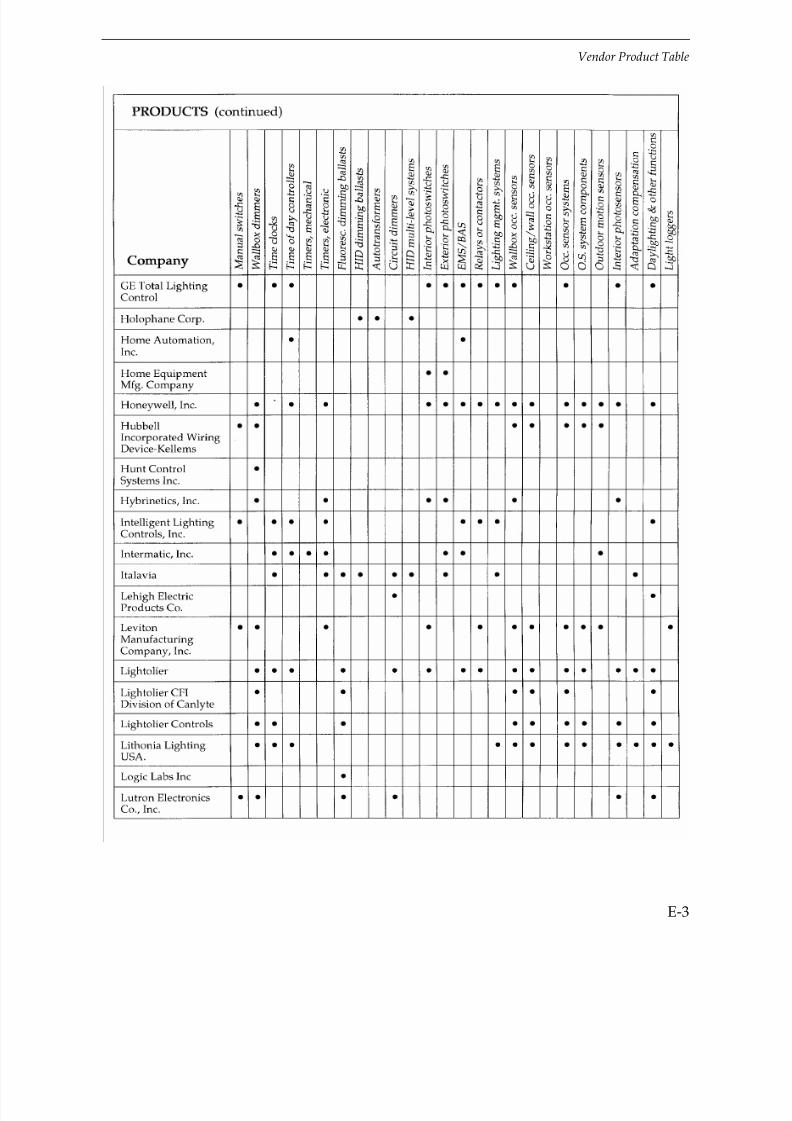
7/21/2019 Lighting Controls Patterns for Design
http://slidepdf.com/reader/full/lighting-controls-patterns-for-design 277/299
Vendor Product Table
E-3

7/21/2019 Lighting Controls Patterns for Design
http://slidepdf.com/reader/full/lighting-controls-patterns-for-design 278/299
Vendor Product Table
E-4

7/21/2019 Lighting Controls Patterns for Design
http://slidepdf.com/reader/full/lighting-controls-patterns-for-design 279/299
Vendor Product Table
E-5

7/21/2019 Lighting Controls Patterns for Design
http://slidepdf.com/reader/full/lighting-controls-patterns-for-design 280/299
Vendor Product Table
E-6
Companies in Table, Addresses, and Phone Numbers
v = voice, f= fax
Advanced Control Technologies, Inc.
8076 Woodland Drive, Indianapolis, IN 46278v: 317-337-0100, f: 317-337-0200
AMX Corp.11995 Forestgate Drive, Dallas, TX 75243v: 800-222-0193, f: 214-907-2053
Architectural Energy Corporation2540 Frontier Avenue, Suite 201, Boulder, CO 80301v: 303-444-4149, f: 303-444-4304
Area Lighting Research, Inc.60 Asbury Road, Hackettstown, NJ 07840v: 908-852-2205, f: 908-852-2816
Aromat Corporation629 Central Avenue, New Providence, NJ 07974v: 908-771-5655, f: 908-771-5656
Beta Lighting1200 92nd Street, Sturtevant, WI 53177
v: 800-236-6800, f: 414-886-2779
Bryant Electric, Inc.185 Plains Road, Milford, CT 06460-2465v: 203-876-3627, f: 203-876-3675
Conservalite Technologies Inc.660 Fame Road, Dayton, OH 45449v: 800-291-1853, f: 800-337-2526
Current Industries, Inc.
1893 E. Aurora Road, Twinsburg, OH 44087v: 888-347-1477, f: 216-963-3060
Dark to Light (DTL)590 Washington Street, Pembroke, MA 02359v: 617-826-1186, f: 617-826-1196
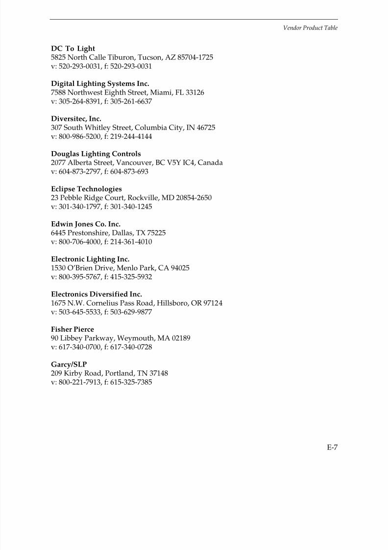
7/21/2019 Lighting Controls Patterns for Design
http://slidepdf.com/reader/full/lighting-controls-patterns-for-design 281/299
Vendor Product Table
E-7
DC To Light5825 North Calle Tiburon, Tucson, AZ 85704-1725v: 520-293-0031, f: 520-293-0031
Digital Lighting Systems Inc.
7588 Northwest Eighth Street, Miami, FL 33126v: 305-264-8391, f: 305-261-6637
Diversitec, Inc.307 South Whitley Street, Columbia City, IN 46725v: 800-986-5200, f: 219-244-4144
Douglas Lighting Controls2077 Alberta Street, Vancouver, BC V5Y IC4, Canadav: 604-873-2797, f: 604-873-693
Eclipse Technologies23 Pebble Ridge Court, Rockville, MD 20854-2650v: 301-340-1797, f: 301-340-1245
Edwin Jones Co. Inc.6445 Prestonshire, Dallas, TX 75225v: 800-706-4000, f: 214-361-4010
Electronic Lighting Inc.1530 O’Brien Drive, Menlo Park, CA 94025
v: 800-395-5767, f: 415-325-5932
Electronics Diversified Inc.1675 N.W. Cornelius Pass Road, Hillsboro, OR 97124v: 503-645-5533, f: 503-629-9877
Fisher Pierce90 Libbey Parkway, Weymouth, MA 02189v: 617-340-0700, f: 617-340-0728
Garcy/SLP
209 Kirby Road, Portland, TN 37148v: 800-221-7913, f: 615-325-7385

7/21/2019 Lighting Controls Patterns for Design
http://slidepdf.com/reader/full/lighting-controls-patterns-for-design 282/299
Vendor Product Table
E-8
GE Total Lighting Control225 Service AvenueWarwick, RI 02886v: 800-852-2778, f : 401-886-6470
Holophane Corp.214 Oakwood Avenue, Newark, OH 43055v: 614-345-9631, f: 614-349-4426
Home Automation, Inc.2709 Ridgelake Drive, Metairie, LA 70002v: 504-833-7256, f: 504-833-7258
Home Equipment Mfg. Company14481 Olive Street, Westminster, CA 92683v: 714-892-6681, f: 714-898-4502
Honeywell Inc.POB 524, Minneapolis, MN 55440-0524v: 612-951-2907 or 800-345-6770, f: 612-951-3465
Hubbell Incorporated Wiring Device-Kellems1613 State Street, Bridgeport, CT 06605v: 203-337-3100, f: 203-579-2892
Hunt Control Systems, Inc.
200 Rome Court, Fort Collins, CO 80524v: 970-484-9048, f: 970-493-4125
Hybrinetics, Inc.POB 14399, Santa Rosa, CA 95407v: 707-585-0333, f: 707-585-7313
Intelligent Lighting Controls, Inc.5229 Edina Industrial Boulevard, Minneapolis, MN 55439v: 612-829-1900, f: 612-829-1901
Intermatic, Inc.Intermatic Plaza, Spring Grove, IL 60081v: 815-675-2321, f: 815-675-1043
ItalaviaCapdevila 3545, Buenos Aires, 1431, Argentinav: 1-545-6770, f: 1-545-3886

7/21/2019 Lighting Controls Patterns for Design
http://slidepdf.com/reader/full/lighting-controls-patterns-for-design 283/299
Vendor Product Table
E-9
Lehigh Electric Products Co.6265 Hamilton Boulevard, Allentown, PA 18106v: 610-395-3386, f: 610-395-7735
Leviton Manufacturing Company, Inc.
59-25 Little Neck Parkway, Little Neck, NY 11362v: 718-281-6384, f: 718-631-6439
Lightolier631 Airport Road, Fall River, MA 02720v: 508-646-3104, f: 508-646-3204
Lightolier CFI Division of Canlyte3015 Louis Amos, Lachine, PQ H8T 1C4, Canadav: 514-636-0670, f: 514-636-0460
Lightolier Controls2413 South Shiloh Drive, Garland, TX 75041v: 800-526-2731, f: 214-271-4077
Lithonia Lighting USAPOB A, Conyers, GA 30207-0067v: 770-922-9000 f: 770-922-1370
Logic Labs Inc.751 Miller Drive, SE. Leesburg, VA 22075
v: 703-779-8144, f: 703-777-5964
Lutron Electronics Co., Inc.7200 Suter Road, Coopersburg, PA 18017v: 610-282-3800, f: 610-282-3044
Macro Electronics Corp.1611 Headway Circle, Building 1, Austin, TX 78754v: 512-837-5100, f: 512-837-1040
MicroLite Corporation
1150 Powis Road, West Chicago, IL 60185v: 708-876-0500, f: 708-876-9654
Milbank WestPOB 6470, Anaheim, CA 92816v: 714-939-9655, f: 714-939-9786

7/21/2019 Lighting Controls Patterns for Design
http://slidepdf.com/reader/full/lighting-controls-patterns-for-design 284/299
Vendor Product Table
E-10
Mitor Industries Inc.POB 4339, Mankato, MN 56002-4339v: 507-387-1599, f: 507-387-7491
MyTech Corporation
706 Brentwood Street, Austin, TX 78752v: 512-450-1100, f: 512-450-1215
North Fork Retrofit511 Carpenter Street, Greenport, NY 11944v: 800-213-2922, f: 516-477-2922
Novitas, Inc.5875 Green Valley, Culver City, CA 90230v: 310-568-9600, f: 310-568-9697
Onset InstrumentsPOB 3450, Pocasset, MA 02559-3450v: 508-563-9000, f: 508-563-9477
Pacific Science & Technology, Inc.64 NW Franklin Avenue, Bend, OR 97701v: 800-388-0770, f: 503-385-9333
Paragon Electric Co., Inc.606 Parkway Blvd., Two Rivers, WI 54241
v: 414-793-1161, f: 414-793-3736
Pass & Seymour/LegrandPOB 4822, Syracuse, NY 13221v: 800-223-4185, f: 315-468-8388
PLC Multipoint3101 111th Street, Southwest, #F, Everett, WA 98290v: 206-353-7552, f: 206-353-3353
Precision Multiple Controls, Inc.
33 Greenwood Avenue, Midland Park, NJ 07432v: 201-444-0600, f: 201-445-8575
Prescolite Division of C.P.M. Lighting, Inc.1251 Doolittle Drive, San Leandro, CA 94577v: 510-577-5381, f: 510-577-5022

7/21/2019 Lighting Controls Patterns for Design
http://slidepdf.com/reader/full/lighting-controls-patterns-for-design 285/299
Vendor Product Table
E-11
RAB Electric170 Ludlow Avenue, Northvale, NJ 07647v: 201-784-8600, f: 201-784-0077
Sensor Switch, Inc.
10 Capital Drive, Wallingford, CT 06492v: 203-265-2842, f: 203-269-9621
Solium Inc.41 Pacella Park Drive, Randolph, MA 02368v: 617-767-7419, f: 617-767-7423
Stocker & Yale, Inc.32 Hampshire Road, Salem, NH 03079v: 603-893-8778, f: 603-893-5604
Superior Electric383 Middle Street, Bristol, CT 06010v: 860-585-4500, f: 860-582-3784
Thomas Controls1015 South Green Street, Tupelo, MS 38801v: 601-842-7212, f: 601-841-5596
Thomas Lighting189 Bullock Drive, Markham, ON L3P 1W4, Canada
v: 905-294-9570, f: 905-294-9811
TORK1 Grove Street, Mount Vernon, NY 10550v: 914-664-3542, f: 914-664-5052
Triad Technologies Inc.2976 Pacific Drive, Norcross, GA 30071v: 770-242-1922, f: 770-242-1944
Unenco Services, Inc.
1350 South Loop Road, Suite 104, Alameda, CA 94502-7081v: 510-337-1000, f: 510-337-1100
Unidim2 East Fayette Street, Fifth Floor, Baltimore, MD 21202v: 410-576-0576, f: 410-576-2437

7/21/2019 Lighting Controls Patterns for Design
http://slidepdf.com/reader/full/lighting-controls-patterns-for-design 286/299
Vendor Product Table
E-12
VIDESSENCE189 Airport Boulevard, Burlingame, CA 94010v: 415-579-7577, f: 415-579-7579
The Watt Stopper, Inc.
2800 De La Cruz Boulevard, Santa Clara, CA 95050v: 800-879-8585, f: 408-988-5373
Wide-LitePOB 606, San Marcos, TX 78667v: 512-392-5821, f: 512-753-1122
Xenergy3 Burlington Woods, Burlington, MA 01803-4543v: 800-967-4393, f: 617-229-4867

7/21/2019 Lighting Controls Patterns for Design
http://slidepdf.com/reader/full/lighting-controls-patterns-for-design 287/299
F-1
FANSWER TO EXERCISES
Do it now :
“A ship in harbor is safe, but that is not what ships are built for. “
—John A. Shedd
“Life is a banquet, and most of us are starving to death.”
—Auntie Mame (By Patrick Dennis)
“Stop swimming so hard/and climb in the boat/with Noah”
—Rumi
Answers to the Exercises at the end of Chapters 2, 3, and 4 are :
Chapter 2, Strategies and Devices (p. 2-46 to 2-48)
1. c
2. Strategy, Device, System
3. Occupancy Sensors : Occupancy ResponsiveTimers : TimingPhotosensors : Daylighting
4. b
5. b
6. a
7. a
8. b
9. d
10. b
11. a
12. d
13. b
14. d

7/21/2019 Lighting Controls Patterns for Design
http://slidepdf.com/reader/full/lighting-controls-patterns-for-design 288/299
Answer to Exercises
F-2
Chapter 3, Design Process (p.3-21 to 3-23)
1. c
2. b
3. c
4. z
5. b
6. e
Chapter 4, After Installation (p. 4-6 to 4-7)
1. c
2. a
3. s
4. h

7/21/2019 Lighting Controls Patterns for Design
http://slidepdf.com/reader/full/lighting-controls-patterns-for-design 289/299
I-10
IINDEX
adaptation compensation, 2-2, 3-20
design patterns, 5-1
adjustment, 4-4, 4-6
audience, 1-2
air-gap disconnect, 2-6
airport concourse, 3-21
auditorium, 5-3
auxiliary switch, 2-9
bidding, 2-34, 3-17
boogey, 3-23
brains, 2-37
building automation system (BAS), 2-35, 3-3
case study, 6-1
case studies, 2-40, 2-41, 6-1 – 6-32
classroom, 5-7, 6-2
client, 3-2
codes, 3-2, B-1

7/21/2019 Lighting Controls Patterns for Design
http://slidepdf.com/reader/full/lighting-controls-patterns-for-design 290/299
Index
I-2
combined controls, 2-37, 2-46
design patterns, 5-1
commissioning, 2-32, 4-1 – 4-6
conference room, 5-17
cooling and heating, 3-10, 3-11, C-4
cost, 3-9
daylighting, 2-1, 2-30, 3-2
calculation, C-3
case study, 6-1
design patterns, 5-1
demand, 3-6, C-3
design steps, 3-1 – 3-9
device, 2-4, 3-12, 5-1
versus strategies, 2-4
diversity, C-2
economics, 2-18, 3-8 – 3-12, C-1 – C-12
electric rate, 3-6, 3-7, C-3
electric use profile, 3-6 – 3-8
electronic switch, 2-5
energy management system (EMS), 2-36
exercises, 2-46, 3-23, 4-6
answers, F-1
exterior lighting, 3-4, B-3

7/21/2019 Lighting Controls Patterns for Design
http://slidepdf.com/reader/full/lighting-controls-patterns-for-design 291/299
Index
I-3
file/storage, 5-26
furnishings, 2-15, 2-16, 4-3
gymnasium, 5-32
hallway, 5-36
harmonic distortion, 3-19
hearing aids, 2-20
HVAC, 2-9, 2-36
HVAC effects, 3-16, 3-11, 3-21, C-4
initiating device, 2-32
installation, 3-14, 4-1
interference on drawings, 3-16
laboratory, 5-49, 6-5
lamp life, 2-12, 3-18, C-10 – C-11
latching switch, 2-5
library reading area, 5-59
library stacks, 5-68, 6-7, 6-10
light logger, 3-6, 3-9, 4-5, C-9
lighting controls, 1-1
reasons for use, 1-1
Lighting Diagnostic and Commissioning System (LDCS), 4-5
Lighting Evaluation System (LES), 3-6
LightPAD, C-2, D-1
load shedding, 2-2

7/21/2019 Lighting Controls Patterns for Design
http://slidepdf.com/reader/full/lighting-controls-patterns-for-design 292/299
Index
I-4
local master controller, 2-44
logical choices, 3-3
lumen maintenance, 2-2
maintenance, 4-5
manual dimmer, 2-24
control signal, 2-27
design patterns, 5-1
dimming efficiency, 2-25
per cent output, 2-27
risks, 2-28
wireless remote, 2-26
manual dimming, 2-2
manual switch, 2-5, B-1 – B-3
manual switching, 2-3 – 2-5, 2-12, 3-11, C-1
manufacturers’ help, 3-11 – 3-14, 4-6
monitoring, 3-8, 3-15, 4-2, C-2
monkey, 2-49
myths, 3-18
occupancy responsive, 2-2
occupancy sensor, 2-5
adjustment, 2-9, 4-3
audible detection, 2-14
automatic on/off, 2-13
7/21/2019 Lighting Controls Patterns for Design
http://slidepdf.com/reader/full/lighting-controls-patterns-for-design 293/299
Index
I-5
occupancy sensor — continued
case studies, 6-1
coverage diagram, 3-13
coverage pattern, 2-11
dead spots, 2-15
design considerations, 2-15
design patterns, 5-1
dry contacts, 2-9
dual technology, 2-7
electromagnetic interference (EMI), 2-16
false-off, 2-7, 2-10, 2-16, 2-18
false-on, 2-7, 2-10, 2-16
features, 2-6
furnishings, 2-15, 4-3
hearing aids, 2-20
high-low control, 2-12
inrush, 2-16, 3-19
light sensor, 2-9
manual on/auto off, 2-12
manual override options, 2-12, 2-13
manual switching, 3-11, 4-4
microphonics, 2-7
no user override, 2-12
7/21/2019 Lighting Controls Patterns for Design
http://slidepdf.com/reader/full/lighting-controls-patterns-for-design 294/299
Index
I-6
packages, 2-6, 2-8
passive infrared, 2-6
personal, 2-9, 2-20, 6-14
risks, 2-22
sensitivity, 2-7
technologies, 2-6
templates, 3-14
time delay, 2-10
time-out warning, 2-6
ultrasonic, 2-6
under-loading, 2-16
zero-crossing, 2-20
occupant interaction, 3-2, 3-24, 4-4, 4-6
office building, 2-38, 2-41, 6-1, 6-12, 6-18
open office, 3-13, 5-77, 6-14, 6-15, 6-16
photoelectric controls, 2-28
adjustment, 2-9
closed- and open-loop, 2-29
risks, 2-16
photosensor, 2-28
adjustment, 2-9, 4-1
control signal, 2-27
field of view, 2-30

7/21/2019 Lighting Controls Patterns for Design
http://slidepdf.com/reader/full/lighting-controls-patterns-for-design 295/299
Index
I-7
photoswitch, 2-28
power pack, 2-10
powerline-carrier system, 2-34
private office, 5-87, 6-16
prospecting, 3-6
punchlist, 4-2
radiation, 3-19
references and resources, D-1
relay system, 2-35 – 2-48
restroom, 2-14, 5-97, 6-16
retail space, 3-3, 5-101, 6-23, 6-25
risks, 2-16, 2-22, 2-24, 2-28, 2-31, 3-16 – 3-23
scene controls, 2-26
shopping mall, 3-20
slam dunks, 3-3
slave pack, 2-11
smart ballast, 2-45
space types, 2-10
airport concourse, 3-21
auditorium, 5-3
classroom, 5-7, 6-2
conference room, 5-17
file/storage, 5-26

7/21/2019 Lighting Controls Patterns for Design
http://slidepdf.com/reader/full/lighting-controls-patterns-for-design 296/299
Index
I-8
gymnasium, 5-32
hallway, 5-36
laboratory, 5-48, 6-5
library reading area, 5-59
library stacks, 5-68, 6-7, 6-10
office building, 2-38, 2-41, 6-1, 6-12, 6-18
open office, 2-13, 5-77, 6-14, 6-15, 6-16
private office, 5-87, 6-16
restroom, 2-14, 5-97, 6-16
retail space, 3-3, 5-101, 6-23, 6-25
shopping mall, 3-20
warehouse, 5-109, 6-28
space types and devices, 3-4
specifications, 3-12, 4-1
strategy, 2-1
symbols, 2-2
success stories, 2-38, 6-1 – 6-31
sweep system, 2-5, 2-35, 2-38 – 2-41
system, 2-4, 2-32, A-1– A-4
task light, 2-20
time clock, 2-22
astronomic correction, 2-22
design patterns, 5-1

7/21/2019 Lighting Controls Patterns for Design
http://slidepdf.com/reader/full/lighting-controls-patterns-for-design 297/299
Index
I-9
risks, 2-24
timer, 2-21
design patterns, 5-1
risks, 2-22
case study, 6-10
timing, 2-2
touch switch, 2-5
transformer-relay, 2-10
trial installation, 3-14
troubleshooting, 4-5
tuning, 2-2
vendors, 2-33, 3-12, 3-13, 3-17, D-4, E-1
warehouse, 5-109, 6-28
Photo credits: page 2-39 – 2-40: courtesy GE Wiring Devices; p. 2-42: Robert Benson;p. 3-8: Bob Rundquist; p. 3-21: James R. Benya; p. 6-3 – 6-4: courtesy Sensor Switch;p. 6-5, 6-6: Scott Gould; p.6-8 – 6-9: courtesy The Wattstopper; p. 6-11– 6-12:Bob Rundquist; p. 6-13 – 6-14: Paul Maze; p. 6-16 – 6-17: courtesy Sensor Switch;p. 6-19 – 6-20: courtesy AlliedSignal; p. 6-21 – 6-22: courtesy The Wattstopper;p. 6-23 – 6-24: courtesy The Wattstopper; p. 6-26 – 6-27: courtesy Lutron Electronics Co.,Inc.; p. 6-29 – 6-30: Bob Rundquist; p. C-8: Bob Rundquist.
Cover art: James Allmon, who also crafted the cartoon-type art in the book.

7/21/2019 Lighting Controls Patterns for Design
http://slidepdf.com/reader/full/lighting-controls-patterns-for-design 298/299
I-10

7/21/2019 Lighting Controls Patterns for Design
http://slidepdf.com/reader/full/lighting-controls-patterns-for-design 299/299